study of dynamics of shock-vortex interaction on flap wing ... · study of dynamics of shock-vortex...
TRANSCRIPT

International Journal of Scientific & Engineering Research Volume 10, Issue 2, February-2019 1540 ISSN 2229-5518
IJSER © 2019 http://www.ijser.org
Study of Dynamics of Shock-Vortex Interaction on Flap Wing by CFD tool
(Self-contained article on ongoing research)
Mukesh Didwania*, Dr. Kamal Kishore Khatri Abstract— the purpose of the flaps is to generate more lift at slower airspeed, which enables the airplane to fly at a greatly reduced speed with a lower risk of stalling. Shock wave-vortex interaction that is generated in external flows (Aerofoil or wing) and internal flows (inlets, nozzles, and combustors) is a complex and often unsteady phenomenon. For analyzing external flow around supersonic solar aircraft with wings of large sweep and small aspect ratio this classical problem in theoretical gas dynamics is very important. Generation of a vortex sheet near the leading edge of the wing and its subsequent rolling into two isolated vortices is the important feature of such flows. These vortices interact with shock waves formed on the aircraft surface elements. Interaction of a supersonic vortex with an oblique shock wave is an important phenomenon because of strong acoustic levels and its adverse effect in aerodynamic performance in high speed fluid flows through flap wing as Wake Turbulence in supersonic aircraft. When a plane shock wave meets a vortex, disturbance is generated, which propagates along the shock wave and results in its deformation. Behind the curved shock wave, the flow field is compressed and rarefied locally and forms acoustic waves. These interesting phenomena are closely related to the shock–turbulence interaction, which is one of the major sources of noise. So this study and investigation will be a good solution to reduce these noise and find the best position of flap where the vortex will still attached to the flap and it is need to analysis the dynamics of Shock-Vortex Interaction of Flap wings by computational fluid Dynamics and it is important to predict the aerodynamics behavior of Shock-Vortex Interaction on flap wings including effect of drag force & lift force and others aerodynamics & thermal factors by flowing air around flap wings and Wake Turbulence for aircraft and then results will be applied to better design the flap wing of aircraft and further this study also can be apply for flap wing of solar power airplane. By choosing proper angle of attack, angle of flap and using software by which different parameters can be generate for geometry of aerofoil. Ansys Fluent can be used which is a simulator for aerofoil. With this software investigation can be do that how an aircraft Flap wing produces lift and drag by changing the values of different factors that produce aerodynamic forces and how flap wing will produce the dynamics of Shock-Vortex interaction and what will be the optimize condition to reduce hazard on flap wing aircraft as Wake turbulence. The objective of this study was to research to assess the levels of acoustic pressure and wake turbulence at different angle of attack with different Mack numbers especially at high Mack number and different flap deflection angle through Flap Wing by a CFD tool and validate the CFD results to Scaled flap wing model of an aircraft by wind tunnel/ PIV system or Numerical Method. Index Terms— Flap wing, Shock Wave, Vortex, Shock-Wave Interaction, CFD, Solar Airplane.
—————————— ——————————
1 INTRODUCTION A wing is a type of fin with a surface that produces aerodynamic forces facilitating movement through air and other gases, or water and other liquids. As such, wings have an airfoil shape, a streamlined cross-sectional shape producing lift. A wing's aerodynamic quality is expressed as its lift-to-drag ratio. The lift a wing generates at a given speed and angle of attack can be one to two orders of magnitude greater than the total drag on the wing. A high lift-to-drag ratio requires a significantly smaller thrust to propel the wings through the air at sufficient lift. The design and analysis of the wings of aircraft is one of the principal applications of the science of aerodynamics, which is a branch of fluid mechanics. The properties of the airflow around any moving object can in principle be found by
solving the Navier-Stokes equations of fluid dynamics. For a wing to produce "lift", it must be oriented at a suitable angle of attack relative to the flow of air past the wing. When this
occurs the wing deflects the airflow downwards, "turning" the air as it passes the wing. Since the wing exerts a force on the air to change its direction, the air must exert a force on the wing, equal in size but opposite in direction. This force manifests itself as differing air pressures at different points on the surface of the wing. The different velocities of the air passing by the wing, the air pressure differences, the change in direction of the airflow, and the lift on the wing are intrinsically one phenomenon. It is, therefore, possible to calculate lift from any of the other three. For example, the lift can be calculated from the pressure differences, or from different velocities of the air above and below the wing, or from the total momentum change of the deflected air. Fluid dynamics offers other approaches to solving these problems—and all produce the same answers if done correctly. Given a particular wing and its velocity through the air, debates over which mathematical approach is the most convenient to use can be mistaken by novices as differences of opinion about the basic principles of flight. Usually, aircraft wings have various devices, such as flaps or slats that the pilot uses to modify the shape and surface area of the wing to change its operating characteristics in flight. Flaps are a type of high-lift device used to increase the lift of an aircraft wing at a given airspeed. Flaps are usually mounted on the wing trailing edges of a fixed-wing aircraft. Flaps are used to lower the minimum speed at which the aircraft can be safely flown, and to increase the angle of
———————————————— • Mukesh Didwania is currently pursuing PhD degree program in
Mechanical Engineering in Career Point University, Kota, India, PH-7340022160. E-mail: [email protected]
• Dr. Kamal Kishore Khatri is guide of Research Scholar of Career Point University, Kota, India, PH-9974398431. E-mail: [email protected]
IJSER
International Journal of Scientific & Engineering Research Volume 10, Issue 2, February-2019 1541 ISSN 2229-5518
IJSER © 2019 http://www.ijser.org
descent for landing. Flaps also cause an increase in drag, so they are retracted when not needed. Flaps is used to generate more lift at slower airspeed, which enables the airplane to fly at a greatly reduced speed with a lower risk of stalling. This is especially useful during takeoff and landing. When extended further, flaps also generate more drag which slows the airplane down much faster than just reducing throttle. Extending the wing flaps increases the camber or curvature of the wing, raising the maximum lift coefficient or the upper limit to the lift a wing can generate. This allows the aircraft to generate the required lift at a lower speed, reducing the stalling speed of the aircraft, and therefore also the minimum speed at which the aircraft will safely maintain flight. The increase in camber also increases the wing drag, which can be beneficial during approach and landing, because it slows the aircraft. In some aircraft configurations, a useful side effect of flap deployment is a decrease in aircraft pitch angle, which lowers the nose thereby improving the pilot's view of the runway over the nose of the aircraft during landing. In other configurations, however, depending on the type of flap and the location of the wing, flaps can cause the nose to rise (pitch-up), obscuring the pilot's view of the runway. There are many different designs of flaps used, with the specific choice depending on the size, speed and complexity of the aircraft on which they are to be used, as well as the era in which the aircraft was designed. Plain flaps, slotted flaps, and Fowler flaps are the most common. Krueger flaps are positioned on the leading edge of the wings and are used on many jet airliners. [21] The study of shock wave/vortex encounters has been a fertile field of investigation for several decades. The interaction of a concentrated vortex and a shock wave may occur in many situations of practical interest. In the operational environment of supersonic aircraft and missiles, the interaction may be a result of vortices created by the forward components of a supersonic vehicle convecting downstream and interacting with shock waves formed over aft surfaces or shock waves present in front of the air intake system of the vehicle, leading to performance deterioration. In addition, the ‘‘shock-associated noise’’ generated in the interaction is an important factor in the design of advanced jet engines because of the effect on community noise and aircraft interior noise, among other things. Other fields where the study of shock vortex encounters is of importance include the case of helicopter blades operating at supercritical speeds and fuel-air mixing enhancement in the combustor of a supersonic combustion ramjet. [1] The early studies on shock-vortex interactions focused primarily on the development of predictive linear theories that were compared with experimental results. Later on, research efforts concentrated on the use of numerical methods for analyzing the problem. Some of the first
successful numerical techniques included finite-difference schemes or spectral methods to solve the Euler equations coupled with shock fitting techniques across the shock. Indeed, the early time behavior of the flow field generated in a shock/vortex encounter can become quite complex, depending on the strength of both the shock wave and the vortex field. Shock fitting techniques have been used with success [2], but it is generally agreed that they are difficult to apply in cases of strong interactions. The shock-capturing approach seems to have been first considered in [3], and schemes of the shock-capturing family have been commonly used in the last decade [4]. The use of state of the art High Resolution Shock Capturing (HRSC) schemes has been reported in recent studies of various aspects of the shock/vortex interaction problem [5], [6], [7]. Shock wave-vortex interaction that is generated in external flows (Aerofoil or wing) and internal flows (inlets, nozzles, and combustors) is a complex and often unsteady phenomenon. For analyzing external flow around supersonic aircraft with wings of large sweep and small aspect ratio this classical problem in theoretical gas dynamics is very important. Generation of a vortex sheet near the leading edge of the wing and its subsequent rolling into two isolated vortices is the important feature of such flows. These vortices interact with shock waves formed on the aircraft surface elements. Two isolated vortices are usually formed in the flow around a delta wing at subsonic speeds at some incidence angles. These vortex structures can enter the engine inlet of a supersonic aircraft. The flow-rate, drag, and other parameters of this propulsion element significantly depend on the interaction mode of the vortex and the shock wave that always formed ahead of a supersonic inlet engine. Such situations can lead to problems for a supersonic aircraft. The vortex can interacts with the aircraft surface in supersonic external flow, which significantly alters the lifting and moment characteristics of wings and other aircraft elements. Loss of stability and controllability of the aircraft is the result of changes in the force characteristics so Interaction of a supersonic vortex with an oblique shock wave is an important phenomenon because of strong acoustic levels and its adverse effect in aerodynamic performance in high speed flows. The experimental and numerical works on shock-vortex interactions for wings and aircraft are extensively presented by a number of researchers. If the vortex intersects the shock wave, two interactions types are possible: (1) Interaction of the vortex with the shock wave perpendicular to the vortex axis; (2) Interaction of the vortex with the shock wave inclined to the vortex axis. [8] The first type of interaction was experimentally studied in [9], [10] and the second type was considered in [11]. It was
IJSER

International Journal of Scientific & Engineering Research Volume 10, Issue 2, February-2019 1542 ISSN 2229-5518
IJSER © 2019 http://www.ijser.org
shown in these works that, in the first case of interaction, the vortex break down, and a reverse flow region with flow unsteadiness appears. There are a few numerical works in high supersonic where the interaction of the vortex and the shock wave is very strong causing numerical instabilities. Some vortex-shock wave interaction regimes with vortex explosion were observed in some works [12], whereas no vortex breakdown was obtained in other works [13]. Therefore, it is necessary to develop a mathematical model for predicting experimentally generated vortices in a complex (often unsteady) flow types such as interaction of a vortex with an oblique shock wave. There is little works to study on interaction of a vortex with an oblique shock wave and its reflection. Zhang et al. [14] has studied an oblique shock wave interaction with two vortices at sonic to slightly supersonic flows. The action of a strong external disturbance on the vortex propagating in the flow results in the so-called vortex explosion or vortex breakdown, as was shown in the experimental works of [15], [9]. This phenomenon was observed both in incompressible flows containing vortices and in compressible subsonic and supersonic flows. The meaning of term “vortex explosion” is formation of a point (or a surface) of total stagnation of the flow in the region of interaction of the vortex and the strong disturbance also the formation of a reverse flow region near the vortex centerline. The problem of vortex explosion has not been ultimately solved, even in the case of an incompressible fluid [15]. Various experiments for determining vortex-breakdown conditions were done for an incompressible fluid. Vortex-core radius, intensity of vortex and free-stream Mach number was used as parameters determining the interaction mode, and data on the structure of interaction regimes were obtained. Supersonic circular components of velocity and a wake-type vortex were studied experimentally and Quantitative experimental results were obtained [9], [10]. Chatterjee [5] has numerically studied shock wave deformation in shock-vortex interaction. He has introduced a simple model to explain shock structure formation and its dependence on the strengths of the interacting vortex and shock wave. Ellzey et al. [4] have performed a computational study based on a High Resolution Shock Capturing scheme of the interaction of a planar shock wave with a cylindrical vortex. They observed a severe reorganization of the flow field and acoustic levels in the downstream region reflected mainly due to the strength of shock wave.
2 OBJECTIVE The objective of this study was to start the research on analysis and investigate
1. The effect of the strengths of shock waves and vortices on the flow field. 2. The condition for the appearance of the various types of interaction of a vortex with shock wave and its reflection from surface detected & captured by CFD post processing method. 3. To assess the levels of acoustic pressure and wake turbulence at different Mack numbers especially at high Mack number and different flap deflection angle through Flap Wing by a CFD tool. 4. Validate the CFD results to Scaled flap wing model of an aircraft by wind tunnel/PIV system or Numerical Method and apply this research to slotted flap of solar airplane.
3 LITERATURE REVIEW A Report described experimental measurements and theoretical analysis of the flow around a wing with a single slotted flap under two dimensional flow conditions by D. N. FOSTH, H. P. A. H. IRWIN and B. R. WILLIAMS. The particular experimental techniques of testing and measurement were described. The results shown that the measured flow is strongly dependent on the inviscid solution for the flow around the wing and the flap, and that near to the optimum flap position there was only weak interference between the wake from the wing and the boundary layer on the flap. The reasons for the occurrence of an optimum flap position were described, and some comments made on the influence of Reynolds number on this position. [16] A numerical study was performed on a NACA 23012 airfoil with a single slotted flap by Michael Damianov Todorov to examine the aerodynamic coefficients at Reynolds number of 3×10⁶, and for help to identifying the forces acting on a light airplane wing. Besides, in the paper the flow fields around the airfoil with single slotted flap were shown. All calculations were made using a CFD code Fluent. For a turbulent model the Spalart-Allmaras method was chosen. Conclusions were made about the aerodynamic efficiency of the proposed configuration wing-single slotted flap. In [17], it was found the aerodynamic characteristics of an airfoil with single plain flap. The obtained results show that the chosen arrangement of wing-single plain flap is not sufficiently effective from an aerodynamic point of view, although it is attractive with the simple design. Therefore, in the proposed paper another configuration will be studied by authors: an airfoil with a single slotted flap. A NACA 23012 airfoil with a 1.00 m chord has been used in all the CFD simulations. The single slotted flap with a 0.32 m chord, corresponding to 32% chord, has been constructed in such a way as to match the geometry of the baseline airfoil and numerical analysis was performed for a NACA 23012 airfoil with a single slotted flap. All calculations were performed with the fluent code. It was used the Spalart-Allmaras turbulent method. The analysis aimed to identify the aerodynamic forces acting on the proposed wing and
IJSER

International Journal of Scientific & Engineering Research Volume 10, Issue 2, February-2019 1543 ISSN 2229-5518
IJSER © 2019 http://www.ijser.org
flap at Reynolds number of 3×10⁶. The 2D CFD model was used to examine the major features around the proposed configuration wing-single slotted flap. The obtained results were compared with those for the NACA 23012 baseline airfoil and configuration wing- single plain flap. The CFD results for the proposed configuration wing-single slotted flap showed higher lift coefficient than the NACA 23012 baseline airfoil and configuration wing-single plain flap. The drag coefficient is less than that of the configuration wing-single plain flap. The obtained results are better from the aerodynamic point of view. So author concluded that the further work is needed to investigate the influence of the gap and position of axis of rotation of the single slotted flap to improve of the aerodynamic characteristics of designed configuration airfoil-flap. [18] The influence of outboard flaps on the wake of a rectangular wing has been studied by S. Haverkamp, G. Neuwerth, D. Jacob. The potential to alleviate the wake has been shown, the induced rolling moment coefficient was reduced by more than 50%. The flaps produce strong counter-rotating secondary vortex pairs that might trigger instabilities in the vortex system. These instabilities have been studied numerically utilizing the linearized Biot–Savart law. The perturbations with wavelengths of the order of the wing span lead to a strong oscillation of the flap vortex and a weaker oscillation of the tip vortex, thus resulting in the disintegration of the flap vortex. The effective vortex size was significantly increased during this process, but the resulting vortex system appears to be stable. The flap vortex was strongly perturbed due to the instabilities that grow in the vortex system. The growth factor was dominated by the perturbations of the flap vortex, but the best results were achieved for those cases that significantly perturb the tip vortex as well. These were not necessarily the cases where the growth factors are maximal. A sinusoidal external perturbation of the tip vortex by active systems might therefore help to alleviate the wake by ensuring a significant perturbation of the tip vortex. The hazard posed to following aircraft was reduced due to the increase in effective vortex size if counter-rotating secondary vortices were inserted into the wake of the preceding aircraft. The most effective configurations investigated were those with strong secondary vortices that were produced by huge flaps attached to the outer wing. These flaps compromise the usability of the ailerons and increase the load on the outer wing, thus entailing structural problems. The application of outboard flaps was therefore improbable. However, other configurations are possible that lead to an appropriate four-vortex system after the roll-up process was completed. A wing of a conventional transport aircraft with differentially extended inner and outer flaps could be such a configuration. From the wing of this aircraft, a tip vortex pair and an inner and outer flap vortex pair emerge. The tip and outer flap vortices have the same direction of rotation, whereas the inner flap vortex is counter-rotating. The tip and
outer flap vortices might merge because they were located close to each other. The resulting vortex system was composed of an outer vortex pair resulting from the merged outer flap and tip vortices, and a counter-rotating inner vortex pair, thus building a four-vortex wake similar to those presented in this paper. Corresponding experimental and numerical investigations were performed by the authors. [19] A study presented computational results of a NACA0012 base wing with the trailing edge modified to incorporate triangular serrations by H. A. Alawadhi, A. G. Alex, and Y. H. Kim. The effect of the serrations were investigated in three stages, the deflection angle of the serration with respect to the wing chord were examined from -90° to 90° at 10° intervals; the results obtained showed that although larger deflection induces a stronger vorticity magnitude, the strength of the vortex decays faster than compared to smaller deflections. Moreover, the vorticity profile downstream of the wing varies with deflection angle of the serration. Next, the addition of a Clark Y flap to the base wing to analyze the flow pattern and the effect on the flow separation; without serrations attached to the base wing trailing edge, at a high angle of attack, the flow would separate early and would render the flap less effective. The Vortex generator energizes the boundary layer and encourages the flow to remain attached to the flap, allowing for a greater range flap deflection. A wind tunnel experiment was developed and conducted to substantiate the computational analysis in a real world scenario. There was a positive correlation between the results obtained experimentally and computationally. Research was performed on serrations of triangular geometries. Serrations of flat plate trailing edge plate which were relied on the deflection angle as well as the flap gap influenced the flow development on a rear placed flap which is single slotted. The serrations seemed effective during low deflection of the flap angle mainly with the serration length in relation with 13 percent of the flap chord. Research shows the effect of vortices generated from triangular serrations; which decreases the upper surface boundary layer when serrations are placed at the lower surface leading edge. The same idea of serration showed similar results in some studies when positioned on trailing edges. Thus, the effect of trailing edge serrations on the aerodynamic characteristics of the wing was the primary focus of this research paper. This study focused on the computational results for the flow characteristics due to serrations which were also then compared to the experimental results obtained by previous group of Emirates Aviation College undergraduate researchers. These computation results were obtained using Computational Fluid Dynamics software ANSYS FLUENT. The analysis was carried on NACA 0012 airfoil with different configurations of trailing edge serrations and the deflection of the serration angle.
IJSER
International Journal of Scientific & Engineering Research Volume 10, Issue 2, February-2019 1544 ISSN 2229-5518
IJSER © 2019 http://www.ijser.org
Finally, the computational analysis was plotted using Tecplot which was used to compare the impact of the computational analysis and experimental techniques using the wind tunnel. To further, test the ability of the serration the flaps were deflected at a higher angle of attack which showed the formation of reversed flow around the flap surface as depicted below in the image. In addition, the experiments with appropriated configuration were repeated twice to thrice to see any variation in the observation. Although the results were not as favorable as obtained from the tech plot, the reasons might be due to the reduced velocity obtained from the wind tunnel. The experimental models were set up and placed after which the china clay and kerosene mixture was applied to the models. The models were placed at different position along the wind tunnel and the height of the flap was adjusted to see the best position where the vortex is still attached to the flap. Hence, this paper can be concluded by saying that after successful simulations it is found that serrations allow the flow to be energized hence allowing the flaps to be retracted to higher angle of attack. [20] Audrey Rault, Guillaume Chiavassa, and Rosa Donat performed a computational study of the interaction of a planar shock wave with a cylindrical vortex. They used a particularly robust High Resolution Shock Capturing scheme, Marquina’s scheme, to obtain high quality, high resolution numerical simulations of the interaction. In the case of a very-strong shock/vortex encounter, they observed a severe reorganization of the flow field in the downstream region, which seems to be due mainly to the strength of the shock. The numerical data was analyzed to study the driving mechanisms for the production of vorticity in the interaction. The difficulties in the numerical simulation of rotational flow in-homogeneities embedded in compressible flows has been recognized by many authors. In this paper authors combined a particularly robust high resolution shock capturing scheme, the M-PHM scheme, with the multilevel work reduction technique developed by other author to obtain high resolution numerical simulations of a particular model of shock-vortex interaction. Author’s numerical technique, the M&M-PHM scheme, was able to obtain high quality, high resolution simulations of the complex shock structure that results at early times after the interaction as well as the late time evolution of the flow field, for a wide range of vortex and shock strengths. In particular authors provided numerical simulations covering the strong-vortex/strong-shock case, which are rather scarce in the literature. Authors carried out a parametric study of the normal shock/vortex interaction and use the data in the numerical simulations to study the relative role of the different mechanisms responsible for the generation of vorticity in the interaction and its relation with the strong disruption of the vorticity field that occurs immediately after the encounter of a very strong shock with a vortex. Authors observed also that the
disruption is more intense when increasing Mv and that vorticity is generated in the interaction due, mainly, to expansion effects. In addition, this work demonstrated the effectiveness of the M&M-PHM scheme for the numerical simulation of the shock-vortex interaction problem. Authors hoped that their work would raise the level of awareness of the scientific community towards the potential of the M&M-PHM scheme in particular as an effective tool in analyzing not only qualitatively but also quantitatively, the structure and physical properties of complex flow fields. [21] Breakdown of a slender longitudinal vortex caused by the interaction with a normal shock was studied with a numerical solution of the Euler and the Navier-Stokes equations for time-dependent, three- dimensional, supersonic flow at a free stream Mach number of 1.6 and deferent vortex strengths by O. Thomer, W. Schroder and E. Krause. When breakdown occurs, a free stagnation point is formed downstream from the shock, followed by a region of reversed ow with a bubble-like flow structure. The burst part of the vortex grows in the axial and radial directions until the bubble reaches a stable position. The shock remains normal near the axis of the vortex but is curved further away from it. The flow downstream from the shock is slightly oscillating. The numerical results clearly reveal the time-dependent flow structure in the axial and the radial direction. The results compare well with recent experimental findings. The investigation of the normal shock-vortex interaction yields two types of flow fields downstream from the shock. Depending on the inflow parameters a weak interaction with no vortex breakdown was observed, and a strong interaction with a bubble-like vortex breakdown. The calculations show that a slender vortex propagating across a normal shock does not necessarily leads to breakdown. If the circulation of the vortex is small and if the axial velocity profile is uniform, the vortex does not change its overall shape. By increasing the vortex strengths, the free stream Mach number or the vortex defect of the axial flow the shock vortex interaction leads to a free stagnation point on or nearby the vortex axis, which can be understood as the initialization of vortex breakdown. The results obtained indicate, that the flow structure of the burst part of the vortex as simulated with the numerical solution agrees well with experimental observations. Several ring-like, slightly oscillating vortex structures are formed immediately downstream from a stagnation point on the axis. For certain ow conditions strong upstream ow motion, even supersonic ow may occur near the axis. A breakdown criterion was derived that showed good agreement with numerical and experimental findings. [22] Interaction of a supersonic vortex with an oblique shock wave is an important phenomenon because of strong acoustic levels and its adverse effect in aerodynamic
IJSER

International Journal of Scientific & Engineering Research Volume 10, Issue 2, February-2019 1545 ISSN 2229-5518
IJSER © 2019 http://www.ijser.org
performance in high speed flows. In this paper, a mathematical model for the vortex was introduced which predicts experimentally generated vortices accurately. Then, the shock wave-vortex interaction was numerically studied using a finite-volume TVD scheme for solving Euler equations. From the results, two interaction regimes were recognized, namely weak and strong regimes. It was shown that vortex breakdown is possible in the case of strong interaction which can significantly alter aerodynamic characteristics of flyers or acoustic field. Results for two case studies were presented here with the freestream Mach numbers of 2.5 and 2.9. The effects of different parameters in vortex breakdown were investigated. It was found that the smaller vortex core sizes with higher intensity may result in stronger interaction at higher Mach numbers leading to vortex breakdown. The aim of present study was to model high Mach number shock vortex interactions and to assess robustness of the developed finite volume TVD scheme for solving compressible flow equations for such complex problems. The other goal was to assess the levels of acoustic pressure at high supersonic Mach numbers of 2.5 and 2.9. authors found that the examples for a successful application of CFD are the codes FLUENT, OVERFLOW of NASA, FLOWer and TAU of Deutshes Zentrum für Luft und Raumfahr, elsA and WAVES of ONERA, CFD++, Star-CCM+ , TAS of Takoku University and UPACS of Japan Institute of Space Technology and Aeronautics. Finally authors concluded that by choosing proper angle of attack and using software by which different parameters can be generate for geometry of aerofoil. FoilSim or Ansys Fluent can be used which is a simulator for aerofoil. With this software investigation can be do that how an aircraft Flap wing produces lift and drag by changing the values of different factors that produce aerodynamic forces and how flap wing will produce the dynamics of Shock-Vortex interaction and what will be the optimize condition to reduce hazard on flap wing aircraft as Wake turbulence. [23]
4 RESEARCH GAP IDENTIFIED By the literature review it found that there is some work on study and analysis of Shock-vortex Interaction for aircraft wing but there is no anymore work on analysis of dynamics of Shock-vortex Interaction for Flap wings and It found that Interaction of a supersonic vortex with an oblique shock wave is an important phenomenon because of strong acoustic levels and its adverse effect in aerodynamic performance in high speed fluid flows through flap wing as wake turbulence in supersonic aircraft. So now in present scenario it is need to analysis the dynamics of Shock-Vortex Interaction of Flap wings by computational fluid Dynamics and it is important to predict the aerodynamics behavior of Shock-Vortex Interaction on flap
wings including effect of drag force & lift force and others aerodynamics & thermal factors by flowing air around flap wings and then results will be applied to better design the flap wing of aircraft and reduce wake turbulence during landing & Takeoff and further this study can be apply for flap wing of solar power air plane also.
5 IMPORTANCE OF THE PROPOSED RESEARCH Strong acoustic levels & wake turbulence and its adverse effect in aerodynamic performance in high speed fluid flows through flap wing is the result of Interaction of a supersonic vortex with an oblique shock wave and Generation of a vortex sheet near the leading edge of the wing and its subsequent rolling into two isolated vortices is the important feature of such flows. These vortices interact with shock waves formed on the aircraft surface elements. Two isolated vortices are usually formed in the flow around a delta wing at subsonic speeds at some incidence angles. These vortex structures can enter the engine inlet of a supersonic aircraft. The flow-rate, drag, and other parameters of this propulsion element significantly depend on the interaction mode of the vortex and the shock wave that always formed ahead of a supersonic inlet engine. Such situations can lead to problems for a supersonic aircraft. The vortex can interacts with the aircraft surface in supersonic external flow, which significantly alters the lifting and moment characteristics of wings and other aircraft elements. Loss of stability and controllability of the aircraft is the result of changes in the force characteristics. Wingtip vortices can pose a hazard to aircraft, especially during the landing and takeoff phases of flight. The intensity or strength of the vortex is a function of aircraft size, speed, and configuration (flap setting, etc.). The strongest vortices are produced by heavy aircraft, flying slowly, with wing flaps and landing gear retracted ("heavy, slow, and clean"). Large jet aircraft can generate vortices that can persist for many minutes, drifting with the wind. The hazardous aspects of wingtip vortices are most often discussed in the context of wake turbulence. If a light aircraft immediately follows a heavy aircraft, wake turbulence from the heavy aircraft can roll the light aircraft faster than can be resisted by use of ailerons. At low altitudes, in particular during takeoff and landing, this can lead to an upset from which recovery is not possible. ("Light" and "heavy" are relative terms, and even smaller jets have been rolled by this effect.) Air traffic controllers attempt to ensure an adequate separation between departing and arriving aircraft by issuing wake turbulence warnings to pilots. When a plane shock wave meets a vortex, disturbance is generated, which propagates along the shock wave and results in its deformation. Behind the curved shock wave, the flow field is compressed and rarefied locally and forms acoustic waves. These interesting phenomena are closely related to the shock–turbulence interaction, which is one of
IJSER

International Journal of Scientific & Engineering Research Volume 10, Issue 2, February-2019 1546 ISSN 2229-5518
IJSER © 2019 http://www.ijser.org
the major sources of noise. In addition, the ‘‘shock-associated noise’’ generated in the interaction is an important factor in the design of advanced jet engines because of the effect on community noise and aircraft interior noise, among other things. Other fields where the study of shock vortex encounters is of importance include the case of helicopter blades operating at supercritical speeds and fuel-air mixing enhancement in the combustor of a supersonic combustion ramjet. So the research will be a good solution to reduce these noise and find the best position of flap where the vortex will still attached to the flap so it was important to proposed a research on analysis and investigate the Dynamics of Shock wave-vortex interaction on slotted flap wing of solar airplane and the Research is going on.
6 DETAIL METHODOLOGY 1. Aerofoil selection: Symmetrical aerofoil has used because the wings will be hand fabricated and developing a cambered airfoil will be difficult but the thickness distribution was kept identical to the 4-digit series, and a new camber line was defined which allowed for camber to be concentrated near the leading edge. A reflexed camber line was designed to produce zero pitching moment, but has generally not been used. These foils were derived to get good high lift with minimum Cm0 (Primary NACA report R-537 & R-610) This airfoil is an extension of the 4 digit series which provides additional camber lines NACA aerofoil of 5 digit i.e., NACA 23012 has been selected because of higher maximum lift coefficient and minimized thickness in order to maximize the generated thrust [24]. The “NACA” aerofoils are shapes for aircraft wing developed by the National Advisory Committee for Aeronautics (NACA) and in future other wing can select also for comparison the results. [18]
Fig.1. NACA23012 Aerofoil
2. CFD Analysis: Finite Volume Method: The methodology for computation will involve the designing of plain NACA23012 airfoils, single/double slotted flaps and Fluid domain on commercial CAD software CATIA V5/Solid Works. The meshing of the designs for grid generation will done on ICEM CFD ANSYS workbench. The CFD analysis will carried out using commercial code ANSYS FLUENT. The post processing of the results will done using ANSYS CFD POST.
Fig. 2. Aerofoil configurations tested
Fig. 3: Computational domain of flap wing.
3. Fabrication of scaled slotted flap wing with different deflection angles mechanism The basic principle of this study is to investigate the dynamics of shock-vortex interaction on slotted flap wing which is used in aircraft and model is based on NACA aerofoil so for that single or multi slot flap wing is to be fabricated for validation purpose. 4. Validation of CFD results on fabricated Scaled Slotted Flap wings model by Wind tunnel/PIV System/Numerical Method The wing, which had an un-extended chord of (size in ft), will designed to be mounted between the floor and roof turntables of the [size] low-speed wind tunnel. It consisted basically of a steel framework, to which moulding of glass reinforced plastic could be bolted to form the contour of the wing, and to which the flap (and slat, when fitted) could be attached. The flap similarly consisted of a steel core and a glass reinforced plastic skin giving the contour shape. The slat will machined from solid metal. The shape of the lower surface of the wing, as originally built, is shown in Fig. 2 for the flap deflected 30 degrees. To remove the discontinuity in
IJSER
International Journal of Scientific & Engineering Research Volume 10, Issue 2, February-2019 1547 ISSN 2229-5518
IJSER © 2019 http://www.ijser.org
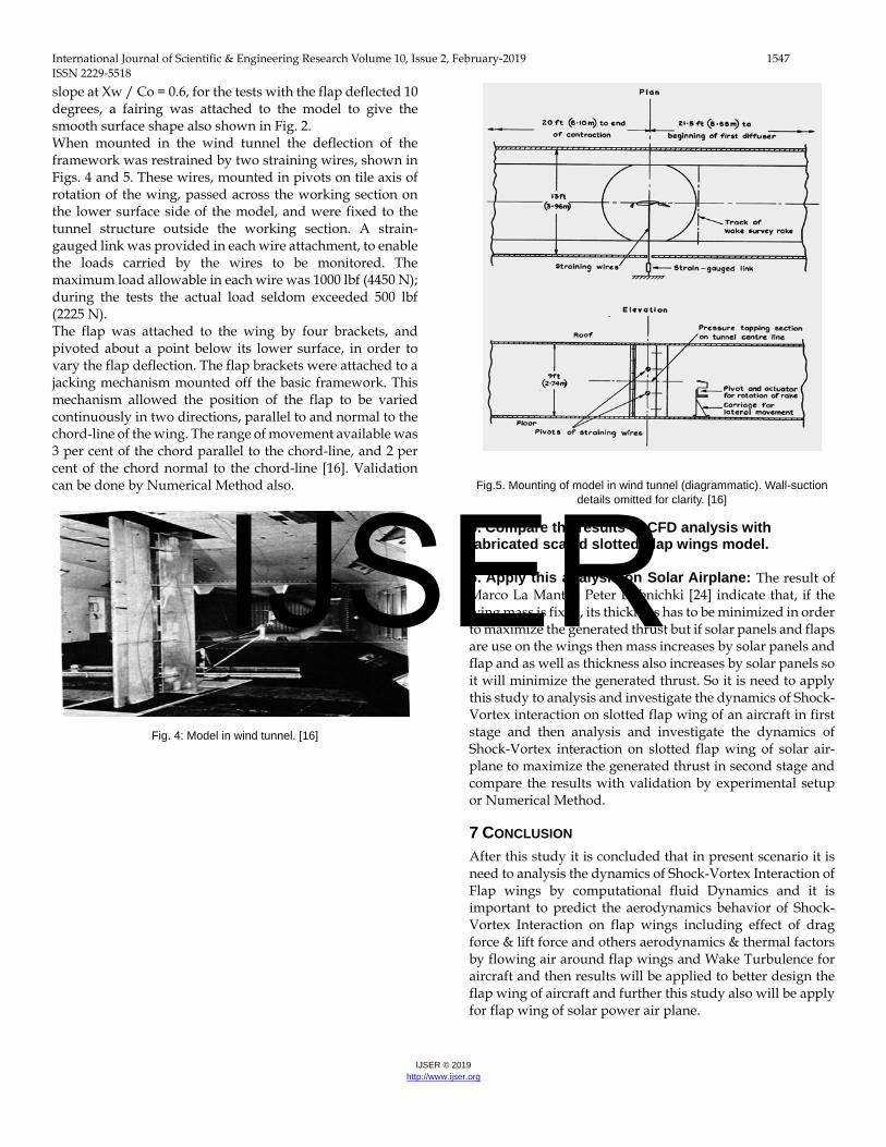
slope at Xw / Co = 0.6, for the tests with the flap deflected 10 degrees, a fairing was attached to the model to give the smooth surface shape also shown in Fig. 2. When mounted in the wind tunnel the deflection of the framework was restrained by two straining wires, shown in Figs. 4 and 5. These wires, mounted in pivots on tile axis of rotation of the wing, passed across the working section on the lower surface side of the model, and were fixed to the tunnel structure outside the working section. A strain-gauged link was provided in each wire attachment, to enable the loads carried by the wires to be monitored. The maximum load allowable in each wire was 1000 lbf (4450 N); during the tests the actual load seldom exceeded 500 lbf (2225 N). The flap was attached to the wing by four brackets, and pivoted about a point below its lower surface, in order to vary the flap deflection. The flap brackets were attached to a jacking mechanism mounted off the basic framework. This mechanism allowed the position of the flap to be varied continuously in two directions, parallel to and normal to the chord-line of the wing. The range of movement available was 3 per cent of the chord parallel to the chord-line, and 2 per cent of the chord normal to the chord-line [16]. Validation can be done by Numerical Method also.
Fig. 4: Model in wind tunnel. [16]
Fig.5. Mounting of model in wind tunnel (diagrammatic). Wall-suction details omitted for clarity. [16]
5. Compare the results of CFD analysis with fabricated scaled slotted Flap wings model. 6. Apply this analysis on Solar Airplane: The result of Marco La Mantia, Peter Dabnichki [24] indicate that, if the wing mass is fixed, its thickness has to be minimized in order to maximize the generated thrust but if solar panels and flaps are use on the wings then mass increases by solar panels and flap and as well as thickness also increases by solar panels so it will minimize the generated thrust. So it is need to apply this study to analysis and investigate the dynamics of Shock-Vortex interaction on slotted flap wing of an aircraft in first stage and then analysis and investigate the dynamics of Shock-Vortex interaction on slotted flap wing of solar air-plane to maximize the generated thrust in second stage and compare the results with validation by experimental setup or Numerical Method.
7 CONCLUSION After this study it is concluded that in present scenario it is need to analysis the dynamics of Shock-Vortex Interaction of Flap wings by computational fluid Dynamics and it is important to predict the aerodynamics behavior of Shock-Vortex Interaction on flap wings including effect of drag force & lift force and others aerodynamics & thermal factors by flowing air around flap wings and Wake Turbulence for aircraft and then results will be applied to better design the flap wing of aircraft and further this study also will be apply for flap wing of solar power air plane.
IJSER

International Journal of Scientific & Engineering Research Volume 10, Issue 2, February-2019 1548 ISSN 2229-5518
IJSER © 2019 http://www.ijser.org
FUTURE SCOPE This research can be apply on the study of fuel and oxidizer mixing in combustion chambers of hypersonic flying vehicles with air-breathing engines by CFD tool in future. In such vehicles, there is supersonic flow regime in the combustor causing complications in fuel and oxidizer mixing.
REFERENCES [1] Smart, M. K., Kalkhoran, I. M., and Popovic, S. (1998). Some aspects
of streamwise vortex behavior during oblique shock wave/vortex interaction. Shock Waves 8, 243–255.
[2] Erlebacher, G., Hussaini, M. Y., and Jackson, T. L. (1998). Nonlinear strong shock interactions: A shock fitted approach. Theoret. Comput. Fluid Dynamics 11, 1–29.
[3] Meadows, K. R., Kumar, A., and Hussaini, M. Y. (1991). Computational study on the interaction between a vortex and a shock wave, AIAA J. 29(2), 174–179.
[4] Ellzey, J. L., Henneke, M. R., Picone, J. M., and Oran, E. S. (1995). The interaction of a shock with a vortex: Shock distortion and the production of acoustic waves. Phys. Fluids 7, 172–184.
[5] Chatterjee A (1999) Shock wave deformation in shock-vortex interactions. Shock Waves 9: 95-105.
[6] Erlebacher, G., Hussaini, M. Y., and Shu, C. W. (1997). Interaction of a shock with a longitudinal vortex. J. Fluid Mechanics 337, 129–153.
[7] Grasso, F., and Pirozzoli, S. (2000). Shock-wave–vortex interactions: Shock and vortex deformations and sound production. Theoret. Comput. Fluid Dynamics 13, 421–456.
[8] Ahmad Sedaghat* and Mohammad Amin Aghahosaini, Computation Study of Oblique Shock Wave-Vortex Interaction in Supersonic External Flows, Aeronautics & Aerospace Engineering. (Volume 3 • Issue 2 • 1000132)
[9] Delery JM (1994) Aspects of vortex breakdown. In: Progress in Aerospace Sciences, Pergamon Press, Oxford, 30: 1-59.
[10] Cattafesta L N, Settles G (1992) Experiments on shock vortex interaction.
[11] Smart MK, Kalkhoran I (1995) Effect of shock strength on oblique shock-wave vortex interaction. AIAA J 33: 2137-2143.
[12] Nedungadi A, Lewis MJ (1996) Computational study of the flow fields associated with oblique shock vortex interactions. AIAA J 34: 2545-2553
[13] Corpening G, Anderson JD (19989) Numerical solutions to three-dimensional shock wave-vortex interaction at hypersonic speeds. AIAA J.
[14] Zhang S, Zhang YT, Shuc CW (2006) Interaction of an oblique shock wave with a pair of parallel vortices: Shock dynamics and mechanism of sound generation. Physics of Fluids 18: 1-21
[15] Leibovich S (1983) Vortex stability and breakdown: survey and extention. AIAA J 22: 1192-1206
[16] D. N. FOSTH, H. P. A. H. IRWIN and B. R. WILLIAMS, The Two-Dimensional Flow Around a Slotted Flap, MINISTRY OF DEFENCE AERONAUTICAL RESEARCH COUNCIL REPORTS AND MEMORANDA, Reports and Memoranda No. 3681" September, 1970.
[17] Todorov, M., Aerodynamic Characteristics of Airfoil with Single Plain Flap for Light Airplane Wing, Proc. of ICMT, (2015).
[18] Michael Damianov Todorov, AERODYNAMIC CHARACTERISTICS OF AIRFOIL WITH SINGLE SLOTTED FLAP FOR LIGHT AIRPLANE WING, INTERNATIONAL CONFERENCE of SCIENTIFIC PAPER AFASES 2015 Brasov, 28-30 May 2015.
[19] S. Haverkamp ∗, G. Neuwerth, D. Jacob, Studies on the influence of outboard flaps on the vortex wake of a rectangular wing, Aerospace Science and Technology 7 (2003) 331–339.
[20] H. A. Alawadhi1,a, A. G. Alex1, and Y. H. Kim, CFD analysis of wing trailing edge vortex generator using serrations, EPJ Web of Conferences, 67, 0 20 02 (2014).
[21] Audrey Rault, Guillaume Chiavassa, and Rosa Donat, Shock-Vortex Interactions at High Mach Numbers, Journal of Scientific Computing, Vol. 19, Nos. 1–3, December 2003.
[22] O. Thomer, W. Schroder and E. Krause, Normal Shock Vortex Interaction, paper presented at the RTO AVT Symposium on “Advanced Flow Management: Part A – Vortex Flows and High Angle of Attack for Military Vehicles”, held in Loen, Norway, 7-11 May 2001, and published in RTO MP-069(I).
[23] Ahmad Sedaghat* and Mohammad Amin Aghahosaini, Computation Study of Oblique Shock Wave-Vortex Interaction in Supersonic External Flows, Aeronautics & Aerospace Engineering, Volume 3 • Issue 2 • 1000132.
[24] Marco La Mantia, Peter Dabnichki, Effect of the wing shape on the thrust of flapping wing, Applied Mathematical Modelling, 35 (2011) 4979–4990.
[25] Che Idris A, Saad MR, Zare-Behtash H, Kontis K (2014) Luminescent measurement systems for the investigation of a scramjet inlet-isolator. Sensors 14: 6606-6632.
IJSER