study of failure in fibrous composites subjected to ... · ad-a283 330 ill~ iiiii ill i ~ill...
TRANSCRIPT
Calhoun: The NPS Institutional Archive
Theses and Dissertations Thesis Collection
1994-06
Study of failure in fibrous composites subjected to
bending loads
Yang, Shih-Ting
Monterey, California. Naval Postgraduate School
http://hdl.handle.net/10945/42930
AD-A283 330 Ill~ IIIII Ill I ~Ill 1111111
. .
.. NAVAL POSTGRADUATE SCHOOL ~
Monterey, California
OTIC
SELECT'ED AUG 1 61994
F
THESIS
Study of Failure in Fibrous Composites Subjected to Bending Loads
by
Shih-Ting Yang
June,1994
Thesis Advisor: Yo1mg W. Kwon
Approved for public release; distribution is unlimited.
94-25696 0, . IIIIIIIIMI"'~ 94 8 15 081
REPORT DOCUMENTATION PAGE Form Approved OMB No. 0704-0188
Public: repoctiaa ..... r. .... coiiDdic. of~ II ......... •-a• I --........ iDcludiq tile time ror Nviewiq iDIINdiOQ, ~ cUUDI .. ~ pdlcriaa..t ..-.iliac 11ae dlla --'-l ud _.,.... ..t _.. .. llae mllediae ofiafonuli-. s-1-Nprclia& tbil bunlaa .a-or U1.'J odMr alped of lhit coU.ctioD of W-.aiaa, iDcludiaa ....... (w NC1uciDa .......... 1D w..w..a- HeadquMua SaYicea, Diredonle £or IDf-uo. 0pcnlioa5 lllld RlpOIU. 12151cft"- Davil HiaJa-y, Su.ill! 1204, ArliqcOQ, VA 22202 .... 302, ..tiD die Oftice ofW..a-a~ ud Budad, Pllpawork ReduaioD Project (0704-
01111_ Wuhin- DC 20503.
1. AGENCY USE ONLY 2. REPORT DATE 3. REPORT TYPE AND DATES COVERED June 1994 Master's Thesis
4. 1lTLE AND SUBnll.E STUDY OF FAILURE IN FIBROUS s. FUNDING NUMBERS
COMPOSITES SUBIECfED TO BENDING LOADS (UNCLASSJFIED)
6. AtmiOR(~l Shih-Ting_ Yan_g
7. PERFORMING ORGANIZATION NAME(S) AND ADDRESS(ES) 8. PERFORMING Naval Postll'llduate School ORGANIZATION
Monterey CA 93943-5000 REPORT NUMBER
9. SPONSORING/MONITORING AGENCY NAME(S) AND ADDRESS(ES) 10. SPONSORING/MONITORING AGENCY REPORT NUMBER
11. SUPPLEMENTARY NOTES The views expressed in this thesis are those of the author and do not reflect the official oolicv or POSition of the Deoartment of Defense or the U.S. Government.
12& DISTRIBtrriON/AV AILABD.lTY STATEMENT 12b. DISTRIBUTION CODE Approved for public release· distribution is 1mlimited. *A
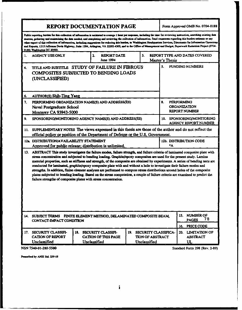
13. ABSTRACT 'Ibis study inw.stigatc:s the failure JDOdes, failure strallfb, 8lld failure criteria of laminated composite plate with stress concentraSi.oa and subjected to bc:lldiDg loadiug. Oraphitrlcpoxy composites are used for the present study. Lamina material properti~ such as stifliK:ss and strallfb, of the composite are obtained by experiments. A series of bending tests are conducted for lamiMted, graphitrJcpo:xy composite plate with and without a hole to inwstigate their failure modes and streugths. In addition. fiDine elCIDCDt analyses are performed to compute stress distributions around holes of the composite plates subjected to beodiug loading. Based oa the stress compuralioa. a couple of failure crileria are examined to predict the failure strengths of composite plates with stress concc:otraliOD.
14. SUBJECT TERMS FINITE ELEMENT METHOD, DELAMINATED COMPOSITE BEAM, 15. NUMBER OF CONTACT-IMPACT CONDI110N PAGES 78
16. PRICE CODE
17. SECURITY CLASSIFI- 18. SECURITY CLASSIFl- 19. SECURITY Cl..ASSIFlCA- 20. UMITATIONOF CAnON OF REPORT CATION OF TinS PAGE TION OF ABSTRACT ABSlRACf Unclassified Unclassified Unclassified UL
NSN 1540-0l-28~5SOO Standard Form 298 (Rev. 2-89)
i
Approved for public release~ distribution is unlimited.
STUDY OF FAILURE IN FIBROUS COMPOSITES SUBJECTED TO BENDING LOADS
by
Shih-Thlg Yang
Major. Taiwan Army B.S, Chung Cheng Institute ofTechnology, August 1985
Submitted in partial fulfillment of the requirements for the degree of
MASTER OF SCIENCE IN MECHANICAL ENGINEERING
Author:
from the
NAVAL POSTGRADUATE SCHOOL June, 1994
Approved By: --- ::=------//voung W. Kwon, Thesis Advisor
Department ofMechanical Engineering
ii

ABSTRACT
This study investigates the failure modes, failure strengths, and failure
criteria of laminated composite plates with stress concentration and subjected
to bending loading. Graphite/epoxy composites are used for the present study.
Lamina material properties, such as stiffness and strength, of the composite
are obtained by experiments. A series of bending tests are conducted for
laminated, graphite/epoxy composite plates with and without a hole to
investigate their failure modes and strengths. In addition, finite element
analyses are performed to compute stress distributions around holes of the
composite plates subjected to bending loading. Based on the stress
computation, a couple of failure criteria are examined to predict the failure
strengths of composite plates with stress concentration. Accesion For
NTIS CRA&I IS) OTIC TAB 0 Unannounced 0 Justification . ._...,_ ......
By . ·-Distribution I
Availability Codes
Dist Avail and I or
Special
A-1 iii
..
TABLE OF CONTENTS
L IN'1'RODUCTION ............................................................................ !
n. LITERA TURY SURVEY ............................................................... .3
m. EXPERWENT ................................................................................ 7
A. J»~J(Jit B~~~ TJB[EORY ••••••••••••••••••••••••••••••••••••••••••••••• ~
B. ~J»ARAJ[1[1!t ....................................................................... Jlll
IV.
A. SJ»ECDIENS WITHOUT A JB[OLE ··-·············-················24
B. SJ»ECJMENS WITH A l/4-INCJB[ JB[OLE AT
1IJIIDit C~ER ..................................................................... ~~~
C. CALCULATIONS FOR MAHRIAL J»ROJ»ERTIES ..... .30
D. CALCULATIONS FOR STRESS & STRESS
CONCENTRATION FACTOR (SCF) ............................... .32
V. FINITE ELEMENT AN'AL YSIS .................................................. 43
A. OVERVIEW ......................................................................... 43
iv
B. TRIANGULAR PLATE BENDING ELEMENT
FORMULATION ................................................................. 44
VL NUMERICAL RESULTS AND DISCUSSION ........................... .51
A. NUMERICAL RESULTS .................................................... 51
B. DISCU~~JlON ....................................................................... ~~
vn. CONCLUSIONS ............................................................................ 62
~PEND~ ..................................................................................... fi'l
L][~T 0~ ~~~CE~ .............................................................. till
INITIAL DISTRIB'VTION LIST .................................................. 70
v

L INTRODUCTION
Many of current modem technologies require materials with mtusual
combination of properties that cannot be met by conventional metal alloys,
ceramics, and polymeric materiaJs. This is especially true for materials that
are needed for aerospace, mtderwater, and transportation applications. For
example, aircraft engineers are increasingly searching for structw'al materials
that are light, strong, stiff, and abrasion-, impact-, and corrosion- resistant.
Rapid increase in the use of advanced composites is primarily due to their
high strength-to-weight ratio and high stiffness-to-weight ratios, making
them ideally suited for the high technology construction. Naval structure
applications of composite materials are typically depending on this weight
saving when a composite material is used to fulfill stiffness or strength
requirements. The Navy has used composite materials since at least 1946
when two 28 foot personnel boats were designed using a laminated plastic.
Today, composites are used widely in the fleet and include items such as
submarine hatches and rudders, MK 46 torpedo propellers, minesweeper
htmters, and patrol crafts [Ref. 1].
1

Failure of engineering materials is undesirable for several reasons; i.e,
human lives that are put in jeopardy, economic losses, and the interference
with the availability of products and services. Even though the causes of
failure and behaviors of materials may be known. prevention of failures is
difficult to guarantee. The usual causes are improper material selection and
processing, inadequate design of components, and their misuse. It is the
responsibility of the engineer to anticipate and plan for possible failure and,
in the event that failure does occur, to assess its cause and then take
appropriate preventative measures agaimt future incidents.
The purpose of this study is to investigate the failure modes, failure
strengths, and failure criteria of )aminated composite plates with stress
concentration and subjected to bending loading. Both experimental and
numerical studies are conducted for the study. As an experimental study,
four-point bending tests are undertaken to obtain lamina material properties
as well as to examine failure modes and strengths of laminated composite
plates with or without holes. As a numerical study, fmite element analyses
are performed to determine the stress distributions around the holes. A
couple of failure criteria are evaluated using both the numerical and
experimental studies.
2
IL LITERATURE SURVEY
In recent years, there have been significant studies to determine the
stiffness and strength of laminated composite materials. One of the common
experiments used to define the responses of composite materials is the
flexure test, in which the specimen is subjected to either a central load or
two quarter-point loads. In many cases, results of these tests are computed
by use of formulas based upon a homogeneous material, although
bi-directional (0° -90'} specimens are employed. In other words, the geometry
of the stacking sequence is not taken into account.
In 1949, Hoff [Ref. 2] presented flexure formulas which, although they
were based on an elementary strength of material consideration, appeared to
be quite adequate to describe the bending of unidirectional or bi-directional
beams. These theoretical equations, in conjunction with flexure experiments,
can be utilized to calculate intrinsic material properties. Certain difficulties
are still encountered in the calculations when highly anisotropic composites
are tested. Pagano [Ref. 3] reviewed Hoffs equations and expressed them in
a more convenient form for computational purpose.
3

In 197 4, Hann and Tsai [Ref. 4] presented graphs to determine the
laminate stiffness and strength for the [0°/+45°/90~ boron fiber/epoxy and
declaimed that a set of generalized graphs for all practical laminates of a
given composite can replace the current limitation of one set of graphs for
each discrete laminate.
The first calculation of the effect of a circular hole on the stress
concentration in a plate was published by Kirsch [Ref. 5] in 1898. He dealt
with isotropic plates and computed the stress concentration factor of 3.
Continuous efforts were made by many researchers to work on the stress
concentration for various cases. To predict the strengths of laminated
composites containing through the thickness discontinuities, two related
criteria based on the normal stress distribution were developed. Whitney
and Nuismer [Ref. 6] considered a circular hole of radius R in an isotropic
plate of infinite extent with the origin of the x-y axes system at the center of
the hole. A uniform tensile stress was applied parallel to the y-axis at
infinity. As the first failure criterion, they assumed that failure occurred
when the stress over a characteristic distance, <fo, away from the
discontinuity was equal to or greater than the strength of the unnotched
material. They proposed the second failure criterion stating that failure
4
occurred when the average stress over a distance, 8o' from the disc"ntinuity
equaled to the wmotched laminated strength. The criteria included the size
effect of discontinuity. Later on, Konish and Whitney [Ref. 7] found that
simply scaling the stress distribution for an isotropic plate containing a hole
by a ratio of the isotropic and orthotropic stress concentration factor to get an
approximate stress distribution in an orthotropic plate with a hole might lead
to significant errors even close to the hole boundary, particularly if the
integral of the stress distribution was used as a strength criterion in the
former study. They proposed a simple polynomial which was obtained by
adding sixth and eighth order terms to the isotropic solution in order to get
an approximation for the normal stress distribution adjacent to a circular hole
in an infinite orthotropic plate.
In 1981, Hoff and Muser calculated the stress concentration factors for
circular holes in circular composite plates of cylindrical orthotropy when the
outer edge of the plates were subjected to a uniform uniaxial traction. They
showed that the stress concentration factor can be plotted in a diagram as a
function of Sar (the compliance in radial direction) and S (two times
tangential compliance plus shear compliance) if the ratio R of the plate to the
diameter of the hole was prescribed. They also made a conclusion that the
s

stress concentration factors depended primarily on the local arrangement of
the fiber at the a.Qe of the hole [Ref. 8].
Chang and Chang [Ref. 9] presented a progressive damage model to
assess damage in laminates with arbitrary ply-orientations and to predict
ultimate tensile strengths of notched laminates. They developed a nonlinear
fmite element program for laminates containing a circular hole. They
claimed a good agreement was found between the numerical prediction and
the experimental data.
6
Ill. EXPERIMENT
This section explains the plate bending theory for laminated composites
to obtain composite material properties from bending tests. The experimental
apparatus used, the laboratory condition, and the testing procedure are also
described.
A. PLATE BENDING THEORY
Because the flexural test is performed to obtain material properties of a
graphite/epoxy composite, the plate bending theory for laminated composites
is reviewed below.
For the classical plate bending theory, the following assumptions are
made. It is assumed that the laminate thickness is small compared to its
lateral dimensions. It is also assumed that there exists a perfect bonding
between any two laminae. That being so, the laminae are not capable of
sliding over each other and they have continuous displacements across the
interface. It is made another important assumption: namely, a line originally
straight and perpendicular to the laminate midplane remaines so after
deformation.
7
Finally, the so-called Kirchhoff assumption is made which states that
in-plane displacements are linear ftmctions of the thickness and interlaminar
shear strains in the x-z and y-z planes are negligible. These assumptions
reduce the laminate behavior to a two dimensional analysis of the laminate
midplane.
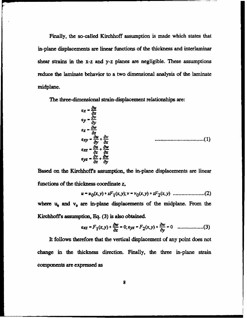
The three-dimensional strain-displacement relationships are:
iJu Ex--ax 8v Ey•-c}y aw Ez--iJz iJu iJv
E%)1 • 'a.Y +-ax ••••••••••••••••••••••••••••••••••(}) au aw Exz--+iJz ax av aw Eyz--+iJz iJy
Based on the Kirchhoffs assumption, the in-plane displacements are linear
functions of the thickness coordinate z,
u- uo(x,y) + zF 1 (x,y); v - vo(x,y) + zF 2(x,y) •..••••.........••.•.. (2)
where 11o and v0 are in-plane displacements of the midplane. From the
Kirchhoffs assumption, Eq. (3) is aJso obtained.
aw aw Ex: - F 1 (x,y) + a% - 0; Eyz - F 2(x,y) + ay - 0 •••.•••.•••••••..• (3)
It follows therefore that the vertical displacement of any point does not
change in the thickness direction. Finally, the three in-plane strain
components are expressed as
8

......................... ( 4)
where
auo a2w
E~ Ox
{:~ ]--ax2
Eo - avo a2w ')' Oy ay2
£0 auo avo 2a2w X)' -+-Oy Ox axoy
Equation ( 4) can be expressed in the compact form as given bellow:
[
EX ] E~ { kx ] ey - E~ + ky
EX)' 20 kxy X)'
.• , ....•................. (5)
Now, it is considered a composite made of n stacked layers or plies. Let
t be the tota! thickness of the laminated composite plate. Then, the
constitutive relationship for the k-th layer is
[ a]k - [QJk[E]k ••••••••••••••••••••.....•••...••.. (6)
where ( Q) k is the transformed reduced stiffness matrix. Substitution of
Eq.(S) into Eq.(6) yields
[a]k- rQJJ eol + Z(QJk[k] .........•........................ (7)
Since a laminated composite is in the state of plane stress, there are three?
stress components. The three stress components produce the following stress
resultants:
9
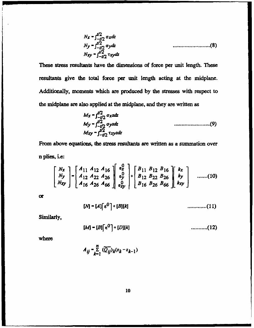
Nx - f_~2 axdz
Ny- f-1n aydz
Nxy • f-2112 Txydz
......................... (8)
These stress resultants have the dimensions of force per unit length. These
resultants give the total force per unit length acting at the midplane.
Additionally, moments which are produced by the stresses with respect to
the midplane are also applied at the midplane, and they are written as
Mx - f-2112 axzdz
My - f-_2t/2 ayzdz
Mxy • f-_2112 Tryzdz
..•..................... (9)
From above equations, the stress resultants are written as a summation over
n plies, i.e:
..•.... (10}
or
••••••.•••••• ( 11)
Similarly,
[M] - [BJf e0l + [D](k] ........... (12}
where
10
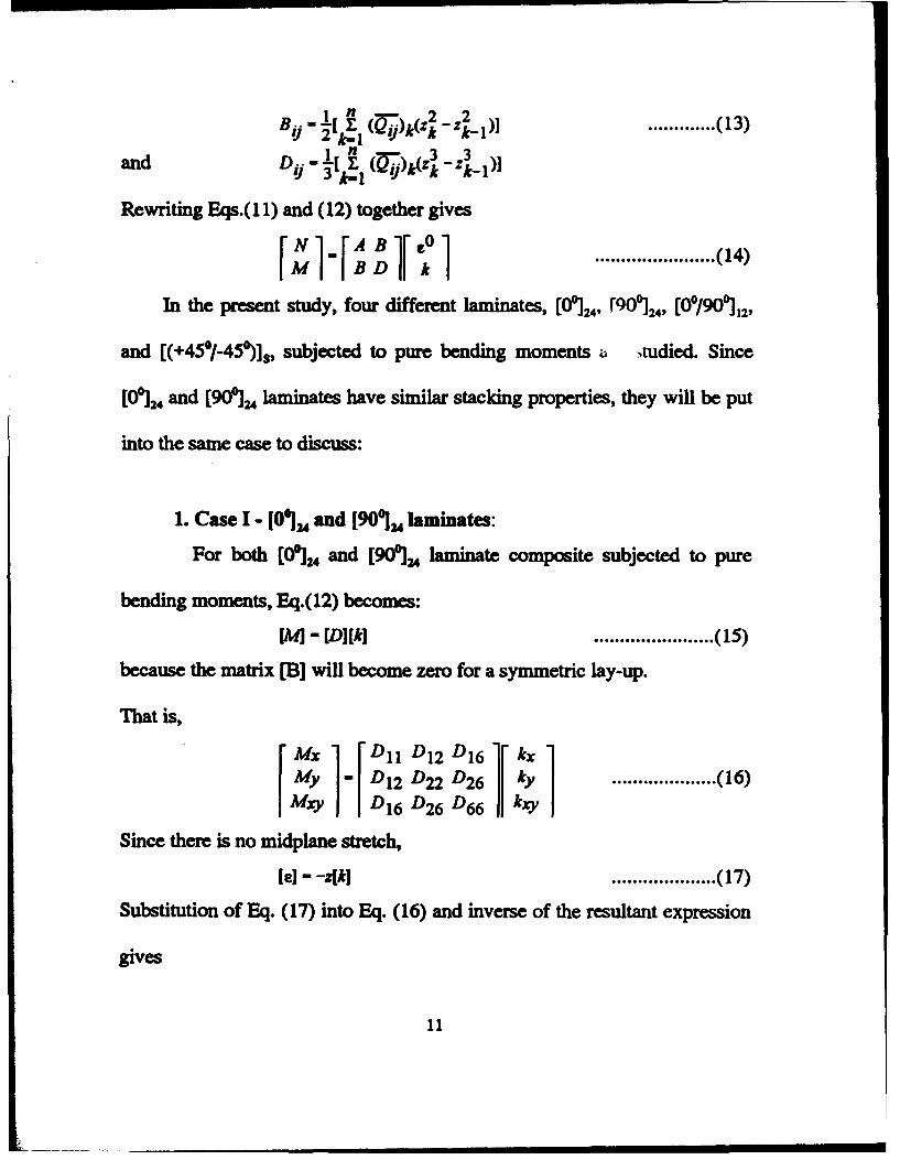
1 n - 2 2 Bij- 2[~1 (Qij)k(zk -zk-l )]
and D .. -1( f (Q. ·)k(zk3 - zk3 1 )] I) 3 k-1 I) -
Rewriting Eqs.(11) and (12) together gives
............. ( 13)
....................... ( 14)
In the present study, foW' different laminates, [00]24, f90o:J24, [0°/90o:l12,
and [(+45°/-45~]5, subjected to pw-e bending moments a ~tudied. Since
[Oo:J24 and [90o:J24 laminates have similar stacking properties, they will be put
into the same case to discuss:
1. Case I - [O~u and [90'Ju laminates:
For both [00)24 and [900]24 )aminate composite subjected to pure
bending moments, Eq.(12) becomes:
[M)- [D](k) ....................... ( 15)
because the matrix [B] will become zero for a symmetric Jay-up.
That is,
f ~; 1-r~:~ ~~ ~~: 1r :; 1 Mry D16 D26 D66 kxy
.................... ( 16)
Since there is no midplane stretch,
[e)- -z(k] .................... ( 17)
Substitution of Eq. (17) into Eq. (16) and inverse of the resultant expression
gives
11
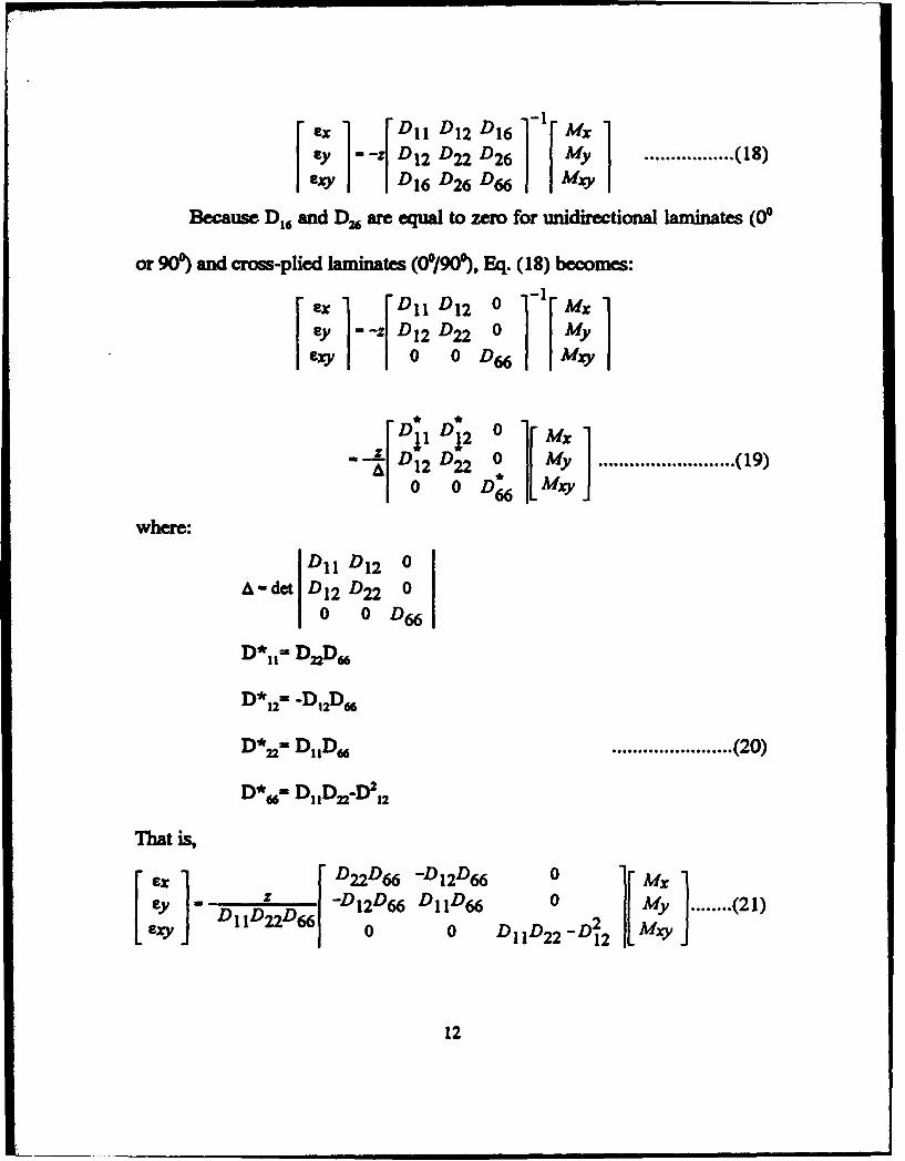
r :; 1-J ~:~ ~~ ~: 1-lr !:; 1 exy ... , Dt6 D26 D66 Mxy
................. ( 18)
Because D16 and D26 are equal to zero for unidirectional laminates (00
or 90') and cross-plied laminates (0'/90'), Eq. (18) becomes:
where:
That is,
f ex l rD11 D12 0 1-lr Mx l Ey ·-z D 12 D22 0 My
exy 0 0 D66 Mxy
--ff~!~ ~~ ; 1[ !:; ] .......................... (19) 0 0 D66 Mxy
D11 D12 0
A•det D12 D22 0
0 0 D66
D*u• DnD"
....................... (20)
[ :; ]--D11D~D66r !~:Z,~ ~~~~= ~ 2l[ Z; ]········<21) exy 0 0 D11D22 -Dl2 Mxy
12

If subjected to a uniaxial pure bending moment: Mx • Mo; My • MllY •0, the
strains are expressed as functions of the layer's thickness, material
properties, and the bending moment. In other words,
ex•-....L_M0 Dn
For the four-point bending test as shown in Fig. 1,
Mo .I!!! 2w
where:
p-load (lb)
a• length of moment arm (in)
w• plate width.
Rewriting Eq.(22) for D11 gives
z zPa Dn - exMo • 2exw
................. (22)
.................... (23)
For [Oo:J24 and [90']24 laminates, D11•2*h3*Q11/3 , D11•2*h3*Q1J3 , and
D21•2*h3*QJ3 where h is a half of the total plate thickness. As a result:
.................... (24)
Since ay - T%J' - 0. Eq. (6) yields
....................... (25)
13
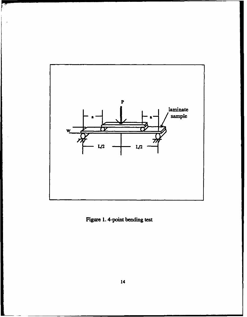
p
Figure 1. 4-point bending test
14
laminate sample

2. Case II- (0°/90'}12 cross-ply laminate:
The derivation is similar to that for [0~ and [90~ laminates.
However, since [00/9<f]12 is n\. . .;ymmetric, the matrix [B] will not reduce to
zero and the situation becomes more complicated.
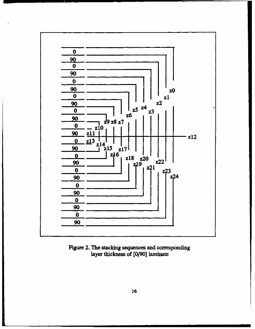
The stacking sequence and the thickness of each corresponding ply
are shown in Fig. 2. From Equation (13), the [A], [B], and [D] matrices for
[0°/9<f]12 are obtained as when each layer has the same thickness.
Au•h*[(Qu) + (Q~],
A12•2h*(Q1J,
~-2h*(Q.J,
A .A -o 16 ~
B11•h2*[(Q11) +4* (Q-zJ]/96, Sn-h~[4*(Q11) + (Q~]/96
B12•Sh~(Q1J196,
B66•Sh~(Q.J,'96,
D11•h3*((Q11) + (Q~]/3,
D12•2h3*(Q1J/3,
D66•2h3*(<4J/3 .
3. Case III- (+45./-4st] laminates :
15
B .A =0 16 ~ ............. (26)
0
22 0
90 0
90 I zO 0 90 I I t zS z4 z3 z2 zl 0 90 ---, z~ z8 z7 z 0 - zlO
90 zll I z12
0 !!J z114 90 1 zlS z17 0 ~6 ~ z18 z20 90 0 I ,2~9 z; 1 zn z23
90 z'24
0 90 0
90 0
90
Figure 2. The stacking sequences and corresponding layer thickness of [0/90] laminate
16
.

For the [( +45°/-45~J. laminated composite plate, the derivation
procedure is also more complicated than the [00 1 and [90']1aminates. Due
to symmetry, matrix [B1 becomes null and the detail of matrix [D1 is
provided below:
where:
and
r ex 1 rD*tt D*12 D*t6lr Mx 1 ey ·-f D*t2 D*22 D*26 My exy D* 16 D* 26 D* 66 Mxy
D11•h'*[(Q11) + (Q~ +2*(Q1J +4*(~]/6,
D12•h3*[(Q11) + (Q~ +2*(Q1J -4*(~]/6,
D16•D26•h3*[(Q11)- (Q~]/48,
D66•h3*[(Q11) + (Q~ -2*(Q1J 1 /6 ·
.................... (27)
.............. (28)
In this thesis, Eq. (24) and the basic equations of material properties are used
to to compute the elastic modulii Ell' ~' .... etc. The details to calculate
these elastic modulii are given in the later chapter.
17
B. APPARATUS
All the bending tests were conducted in a laboratory whose ambient
temperature is 22.5+2.0°C with an average relative humidity equal to
41+5,;. The MTS 810 Material Test System was used to conduct all the
bending tests.
The materials used during the experimental testing were graphite
fiber/epoxy composites with [Oo:J24, [90o:J24, [0°/9<f]12, and [( +45°/-45~Js
laminates. The experimental samples were cut from different orientation
laminate plates with nominal dimensions as 12" by 12" square and 0.15"
thick into small plates with length of 12" and width of 1". Some samples
were drilled a quarter inch hole at the center. A fixture was designed to hold
the composite samples in a simply supported configuration. Each sample
was positioned on the top of the supporters. A four-point bending test was
performed as shown in Fig 1.
Several strain gauges (1/4 inch CEA.-13-250UN-350, with gauge factor
2.120 + 0.5,;) were moWlted on both sides of the samples. One strain gauge
was placed at the center of each side of [Oo:J, [(0°/90~J5, and [ +45°/-45~Js
laminae (without hole) for the purpose of obtaining the properties of
laminated composite. A [goG] laminate sample (without hole) was moWlted
18

with two strain gauges on each side, one in the longitudinal direction, and
the other in the transverse direction.
Additional strain gauges were mounted on each sample with a 1/4H hole
at the center to measure the strain response of the sample under load more
accurately. Figures 3 to 6 show the locations of the strain gauges on each
sample. Tests of these samples were conducted with the MTS material
testing machine at a crosshead speed of 0.12 in/min (or 0.305 mm/min). The
MTS machine provided readings and a force-displacement print-out on the
x-y plotter (HP 7054A x-y Recorder) for the applied force and the
measurement of the deflection of the sample. Strain gauge outputs were
connected to a Measurements Group SB-10 Switch & Balance Unit, and
readouts, in microstrain, provided by Measurement Group P-3500 Strain
Indicator. The results were read and recorded manually upto the fracture of
the sample.
19
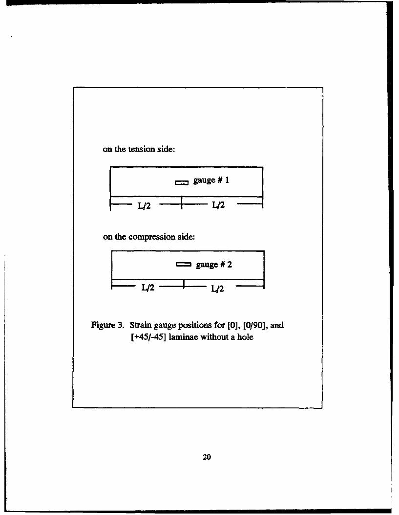
on the tension side:
~gauge# 1
L/2 ---+:-- L/2
on the compression side:
t:::l gauge # 2
L/2 --+-- L/2
Figure 3. Strain gauge positions for [0], [0/90], and [ +45/-45] laminae without a hole
20

on the compression side:
O.S"
on the tension side:
0.5"
O.S"
~-o.s" t'- ,..!-"
~------------~~------------------1]-b.-#3 #4
Figure 4. Strain gauge locations for [90] laminate without a hole
21
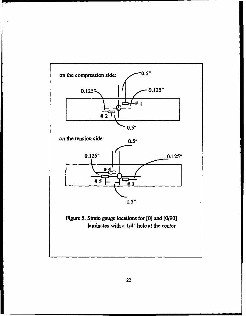
on the compression side: 0.5"
0.125" 0.125"
on the tension side: 0.5"
r.-0.125" 0.125" --
1.5"
Figme S. Strain gauge locations for [0] and [0/90] laminates with a 1/4" hole at the center
22
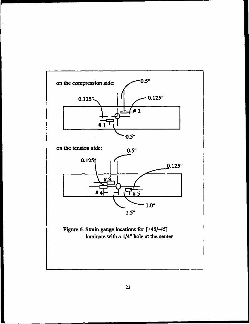
on the compression side: 0.5"
0.125" 0.125"
#1
0.5"
on the tension side: 0.5"
0.125 r.--
1.5"
Figure 6. Strain gauge locations for [ +45/-45] laminate with a 1/4" hole at the center
...___ _____ j
23

IV. EXPERIMENTAL RESULTS
'Ibis section presents the results as obtained from the experiments.
While some description of the experimental and calculated results is
provided here, a more detailed explanation and physical interpretation of the
results will be given in the later chapter. In order to ensure consistency in
recording loading responses, samples were placed as uniformly as possible
with strain gauges in the same positions. The same crosshead speed and the
same procedures were also employed for each separate test. The results are
presented graphically and in a tabular form.
A. SPECIMENS WITI'OUT A BOLE
The four different laminated composite samples without a hole were
tested to provide a basis to compute the material properties and to compare
with samples with a hole. Tables 1 to S show the loads and strains recorded
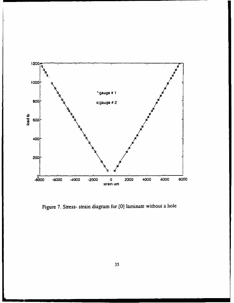
from each experiment for the samples. The load vs. strain relationship is
plotted in Figures 7 to 14.
24

Table 1. results for a [0] laminate without a hole
load (lb) gauge# t•• gauge# 2
ss.s 395 -399
104 736 -745
ISO 1,015 ·1,057
256 1,760 ·1,795
298 2,035 ·2,080
354 2,396 ·2,456
402.5 2,712 ·2,786 -.
434 2,916 -3,001
497 3,319 -3,419
525.5 3,506 -3,617
596.5 3,950 -4,089
627 4,138 -4,289
694 4,561 -4,742
717 4,701 -4,892
780 5,082 -5,303
811.5 5,271 -5,509
887 5,129 -6,009
933 5,998 -6,305
986 6,315 -6,654
1,040 6,650 -7,007
1,070 6,836 -7,193
1,100 6,995 -7,366
1,130 7,177 -7,565
1,166 7,385 -7,779
1,200 7,558 -7,864
• *:failure occurred at approximate 1210 lbs.
**: see figure 3 for the strain gauge locations.
2S

Table 2. results for a [90] laminate without a hole
load( lb) gauge 'I# 1•• gauge 'I# 2 gauge 'I# 3
10 22 -941
20 ss -2,264
25 70 -2,924
• *: failure occurred at approximate 28 lbs.
**:see figure 4 for the strain gauge locations.
-18
-46
-62
gauge '1#4
996
2,438
3,160
Table 3. ftSUits for [(0/90)]12 laminate without a hole
load (lb) gauge 'I# 1** gauge#2
29 -798 155
59 -1,644 1,540
90 -2,518 2,344
119.5 -3,332 3,078
149 -4,158 3,835
180 -5,015 4,601
208 -5,822 5,317
240 -6,750 6,126
267 -7,666 6,914
297 -8,652 7,749
326 -9,156 8,660
361 -11,334 9,944
391 -12,962 11,255
• *: failure occurred at approximate 401 lbs.
**: see figure 3 for the strain gauge locations.
26
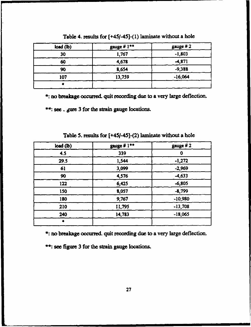
Table 4. results for [+45/-45]-(1) laminate without a hole
load Ob) gauge Ill** gauge#2
30 1,767 -1,803
60 4,678 -4,871
90 8,654 -9,388
107 13,7S9 -16,064
• *: no breakage occurred. quit recording due to a very large deflection.
**: see ... jUI'e 3 for the strain gauge locations.
Table 5. results for [ +45/-45]-(2) laminate without a hole
load (lb) gauge# t•• gauge# 2
4.5 339 0
29.5 1,544 -1,272
61 3,099 -2,969
90 4,576 -4,633
122 6,425 -6,805
ISO 8,057 -8,799
180 9,767 -10,980
210 ll,79S -13,708
240 14,783 -18,065
• *: no breakage occurred. quit recording due to a very large deflection.
**: see figure 3 for the strain gauge locations.
27

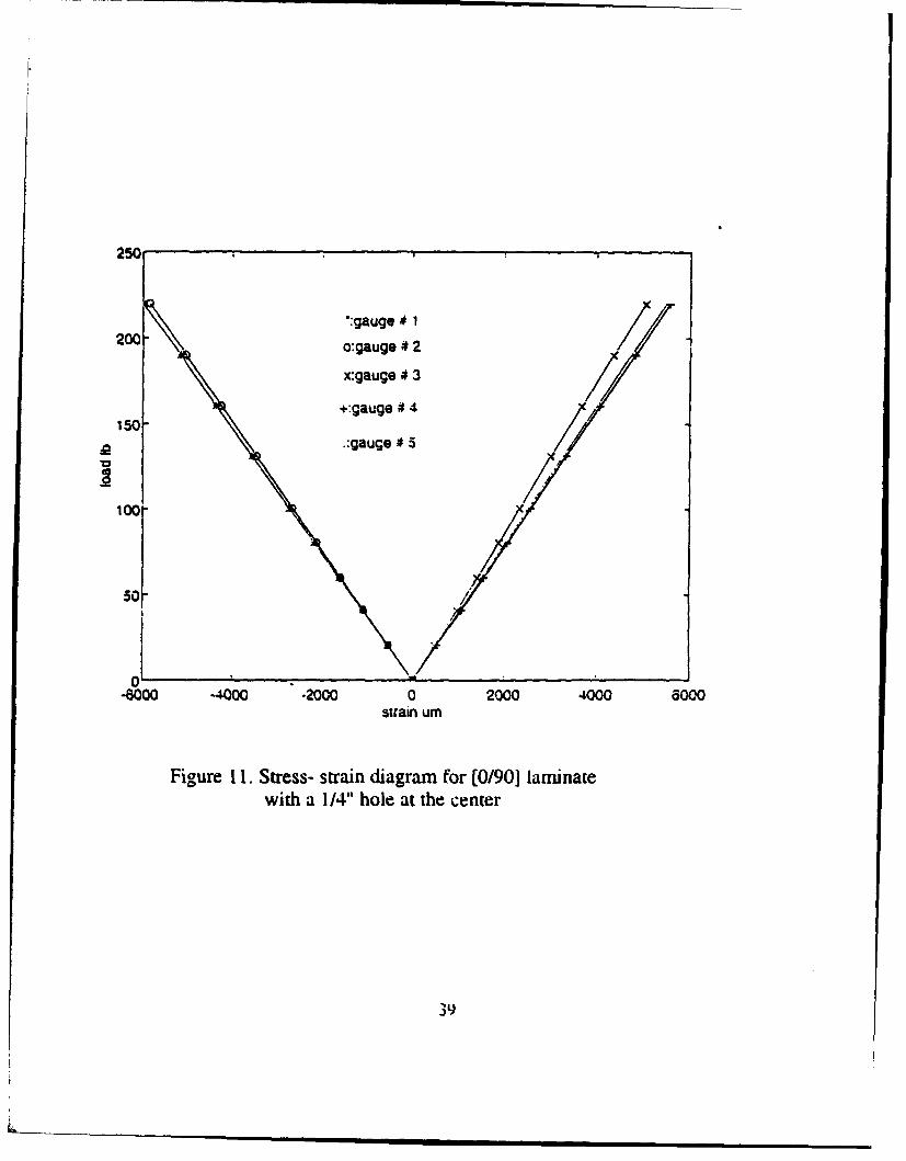
B. SAMPLES WITII A 1/4-INCB BOLE AT THE CENTER
Similarly, three different laminated composite samples, [0~, [(0°/9<f>] 12,
and [(+45'/-45'}]12 with a quartc2' inch hole at the center of the plate were
tested. Five strain gauges were mounted with three on the tension side and
two on the compression side for each sample. The three gauges on the
tension side were placed with two at a distance of 0.5 in. away from the
center and another one at 1.25 in. The locations of strain gauges are shown
in Figures 5 and 6. The results for each sample were recorded in order to
compare them with the data obtained from the previous section (section A) .
Table 6. results for a [( +45/-45)1J1 laminate with a 1/4-inch hole at the center
load (lb) gauge# t•• puge#2 puge#3 puge#4
0 0 0 172 0
29.5 -2,910 -2,834 2,997 2,683
49.5 -5,151 -5,022 5,210 4,711
69.5 -7,834 -7,686 7,908 7,066
84.5 -10,783 -10,670 10,857 9,465
90 -12,282 -12,151 12,320 10,619
•
gauge# 5
0
2,999
5,369
8,180
11,247
12,748
*: no breakage occurred. quit recording due to a very large deflection.
**: see figure 6 for the strain gauge locations.
28
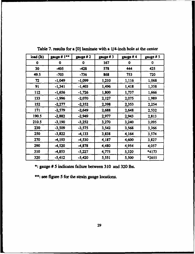
Table 7. results for a [O]laminate with a 1/4-inch hole at the center
load (lb) gauge# 1** puge#2 puge#3 puge#4 gauge# 5
0 0 0 167 0 0
30 -405 -428 578 444 425
49.5 -703 -736 868 753 720
72 -1,049 -1,099 1,210 1,116 1,068
91 -1,341 -1,403 1,496 1,418 1,358
112 -1,656 -1,726 1,800 1,737 1,666
133 -1,996 -2,070 2,127 2,075 1,989
152 -2,277 -2,352 2,398 2,353 2,254
171 -2,579 -2,649 2,688 2,648 2,532
190.5 -2,882 -2,949 2,977 2,943 2,813
210.5 -3,190 -3,252 3,270 3,240 3,095
230 -3,509 -3,575 3,542 3,568 3,366
250 -3,822 -4,133 3,838 4,164 3,574
270 -4,193 -4,530 4,187 4,600 3,827
290 -4,520 -4,878 4,480 4,954 4,057
310 -4,853 -5,227 4,775 5,320 *4173
320 -5,412 -5,420 5,551 5,500 *2655
*:gauge# S indicates failure between 310 and 320 lbs.
**: see figure S for the strain gauge locations.
29
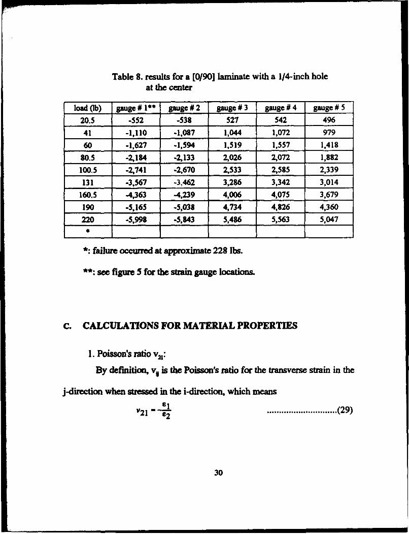
Table 8. results for a [0/90] laminate with a 1/4-inch hole at the center
load (lb) gauge# 1** gauge#2 gauge# 3 gauge#4 gauge# 5
20.S -SS2 -S38 S21 S42 496
41 -1,110 -1,087 1,044 1,072 979
60 -1,627 -1,594 1,519 1,5S7 1,418
8o.s -2,184 -2,133 2,026 2,072 1,882
100.S -2,741 -2,670 2,S33 2,S8S 2,339
131 -3,567 -3,462 3,286 3,342 3,014
160.S -4,363 -4,239 4,006 4,07S 3,679
190 -S,16S -S,038 4,734 4,826 4,360
220 -S,998 -S,843 S,486 S,S63 5,047
• *: failure occurred at approximate 228 lbs.
**: see figure S for the strain gauge locations.
c. CALCULATIONS FOR MATERIAL PROPERTIES
1. Poisson's ratio v21:
By definition, v1 is the Poisson's ratio for the transverse strain in the
j-direction when stressed in the i-direction, which means
............................. (29)
30
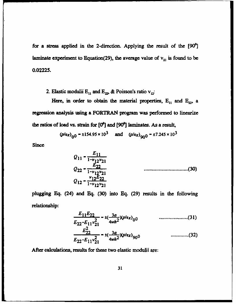
for a stress applied in the 2-direction. Applying the result of the [90'1
laminate experiment to Equation(29), the average value of v 21 is found to be
0.02225.
2. Elastic modulii E11 and Ew & Poisson's ratio v 12:
Here, in order to obtain the material properties, E11 and ~' a
regression analysis using a FORTRAN program was performed to linear..ze
the ratios of load vs. strain for [00] and [90'] laminates. As a result,
(p/ex)00 - ±1S4.9S x 103 and (p/£%)900 - ±1.245 x 10³
Since
En Q11 - 1-vl2"21
Q - En 22 l-v12"21 "12E22
Q12- 1-v12"21
..•.•........................... (30)
plugging Eq. (24) and Eq. (30) into Eq. (29) results in the following
relationship:
E 11 E22 - t(-2L)(ple ) 2 2 x oo
E22-E11 v21 4wh ..................... (31)
............. (32) E~2
----:=--2- - ±{ 3a 2 )(p/ex)90o E22-E11"21 4wh
After calculations, results for these two elastic modulii are:
31

E11• 6.273 X to' psi ; En• 0.3649 X 10⁶ psi
From
we also get
v12•0.382S.
3. Shear modulus G 12:
A Matlab program was written in order to compute the material
property, 0 12• The experimental result of load vs. strain ratio of the
[( +4S0/-4S'>Js laminate was compared with the load vs. strain ratio
calculated from the program using a guessed value of 0 12• The Incremental
Search method was employed to determine the correct guess value for 0 12
iteratively. The shear modulus 0 12 obtained from this way was 1.04Sx106 psi.
D. CALCULATIONS FOR STRESS & STRESS CONCENTRATION
FACTOR (SCF)
The failure load for each sample is shown in Table 9. Here, stresses are
calculated at z• +h or -h (at the top or bottom of the sample) for each
32
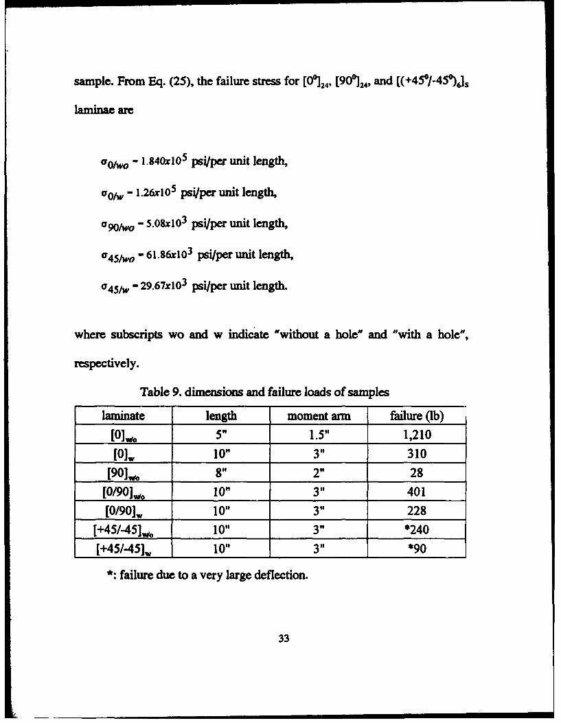
sample. From Eq. (25), the failw-e stress for [0~24• (90~24, and [(+45°/-45~Js
laminae are
aolwo - 1.840xto5 psi/per unit length,
a01w- 1.26xlOs psi/per unit length,
a90iwo- 5.08%103 psi/per unit length,
a4Siwo- 61.86xi03 psi/per unit length,
a4Siw- 29.67xi03 psi/per unit length.
where subscripts wo and w indicate "without a hole" and "with a hole",
respectively.
Table 9. dimensions and failure loads of samples
laminate length moment arm failure (lb)
[Olwo 5" 1.5" 1,210
[O)w 10" 3" 310
[90]w'o 8" 2" 28
[0/90)., 10" 3" 401
[0/90)w 10" 3" 228
(+45/-451wo 10" 3" *240
[+45/-45]w 10" 3" *90
*: failure due to a very large deflection.
33

For [0°/90ct_} 12, the matrices [A], [B], and [D] were calculated from Eq.(26).
Plugging these data into Eq.(l4) and Eq.(7), the failure stress for the
(0°/90ct_}12 laminate are
aoi90-toplwo- 213.86rto3 psi/ per unit length,
ao/90-bottomlwo- 12.S3d03 psi/ per unit length,
ao/90-toplw - 162.13xto3 psi/per unit length,
ao/90-bottomlw- 9.49xto3 psi/per unit length.
Based on these data, the experimental stress concentration factors (SCF) for
laminated composites are 1.46 for the unidirectional plate and 1.32 for the
cra;s-ply plate if the failure occws due to the largest stress at an edge of the
hole.
34
1200\ ' ~ )ll
)IE
• '
•:gauge # 1 I
)IE
800 \ o;gauge # 2 I
I I
:2 )ll
'0 600 \ )ll
as I .2
\ • I
400 J \ ' ~
2001 \ I J
I I I 0
-8000 ·6000 -4000 ·2000 0 2000 4000 oOOO 8000 strain urn
Figure 7. Stress- strain diagram for (0] laminate without a hole
35

3501r-------~------~----~------~------~------~
300 •:gauge # t
o:gauge ;1 2
250 x:gauge tt 3
+:gauge# 4
roo[ .:gauge 115
' 150
I
tOO
50
0~------~------~------~~------~------~------~ 4000 6000 -6000 -4000 ·2000 0
stratn-(u) 2000
Figure 8. Stress- strain diagram for [0] laminate with
a 1/4" hole at the cenrer
36

Figure 9. Stress- strain diagram for [90] laminate without a hole
37

4001 I 350r .,
I •:gauge # 1
3001"' i o:gauge # 2
J 250 ! I
:Q
I I
~200
l .2
1sot- ! 1 I I I I
100j
1 saf
! ! "'1
I J 0' -1.5 -1 -o.s 0 0.5 1.5
strain urn • x10
Figure 10. Stress- strain diagram for [0/90] laminate without a hole
38
250~------~--------------~--------------~~----~
150
100
50
•:gauge ;t 1
o:gauge it 2
x:gauge ;t 3
+:gauge# 4
.:gauge# 5
0~------------~--------~~------~------~------~ -sooo ·2000 0 strain um
2000 4000
Figure 11. Stress- strain diagram for [0/90] laminate with a 1/4" hole at the ~enter
aooo

120
I I
I i 1001"' I I J I
so~ I ~
I * I ~ eor :a
l ~ i I
l ·:gauge t 1 I .a.or -I a: gauge t 2 !
20r -i I I
I I I
0 -2 -1.5 ·1 -o.s 0 0.5 1.5
strain um " x10
Figure 12. Stress- strain diagram for [ +45/-45] laminate without a hole

200
l •:gauge # 1
o:gauge t 2 I i 150r
I
I .. I
I I
J 100r I I
I I
I • so I J
I • I 0 ·2 ·1.5 ·1 -o.s 0 0.5 1 1.5
strain urn ' x10
Figure 13. Stress- strain diagram for [+45/-45] laminate without a hole
41

90
I I
SOt-
l 70r
60r ,Q 501'-'0
~40
•:gauge # 1
o:gauge #2
x:gauge t 3
+:gauge II 4.
.:gauge II 5
I I
l ~
I l
I l
o~--~--~~~~--~--~1 -1.5 ·1 -v.5 0 strain um
0.5
Figure 14. Stress- strain diagram for [ +45/-45] laminate with a 1/4" hole at the center
1.5 ~
x10
V. FINITE ELEMENT ANALYSIS
A.. OVERVIEW
Since the earliest development of the finite element method, a large of
plate beadina elemalts have been developed and reported in the literature.
IU ex•mple, Batoz et al. [Ref. 10], with the purpose of identifying the most
effective elemerlt for the thin plate analysis, presented an assessment of flat
triangular plate bending elements with displacement degrees-of-freedom at
the three earner nodes only. They claimed that the most efficient and reliable
three-node plate bending elements were based on the discrete Kirchhoff
theory and a hybrid stress model. Later on, he [Ref. 11] also presented the
explicit expression of the stiffness matrix of the nine degree-of-freedom
plate btaling triangular element (called discrete Kirchhoff triangle) which
allowed, as he said, a significant reduction of algebraic operations in the
evaluation of the stiffness matrices and bending moments.
In 1983, Fricker [Ref. 12], based on R•zzaque's report, described a new
three-noded triangular element for plate bending with an extra internal
'bubble' function proposed by Irons for making the R•zzaque's element more
43

flexible. He also claimed that his element and that developed by Hansen,
Ba-gan, and Syvertsen were the two most accurate triangular thin plate
elements currently available. Furthermore, Lee and Zhang [Ref.13]
developed a six-node plate bending element based on a modified
Hellinger-Reissener principle and the Reissnei'-Mindlin plate bending theory
to obtain more accurate and reliable solution.
In this thesis, a triangular plate bending element, which was developed
by Tocher[Ref. 15], is used to analyze the laminated composite plates
subjected to a pure bending load and to determine the deflections, strains,
and stresses of the plates.
B. TRIANGULAR PLATE BENDING ELEMENT FORMULATION
The plate, in general, may have any irregular geometry and loading.
The derivations are based on assumptiorw of the small deformation theory,
described in the earlier chapter. A triangular plate element is employed for
the following developement. Each nodal displacement of the element
~ three components: a displacement in the z direction, w; a rotation
about the x axis, w., (derivative of w with respect toy); and a rotation about
44
they axis, w. (derivative of w with respect to x), as shown in Figure 15. The
displacement function, w, is assumed to be
w(x,y) • a 1 + a,x + a'\Y + a4x2 +a c;X)' +a~ + a7x3 + aR(x2y + .xy2) +a
-• [n]a ..................... (33)
where
[n] • [1 x y x1 xy y x3 (xly+xy) y' ) ................. (34)
and
................. (35)
a9
Here, the constants a1, ~~ •••••• , a, must be determined from the nodal
conditions
w(x,y)•q1, wy(x,y)•cu, -w.(x,y)•q, at (x1,y1)•(0,0)
w(x,y)•q., wy(x,y)•Qs, -w.(x,y)•'J6 at (~,yJ•(O,yJ .................. (36)
w(x,y)•q,, wy(x,y)•q,, -w.(x,y)•qg at (x,,yJ•(x,,yJ
The local y axis is taken the same as the line connecting the node 1 and node
2 with the origin placed at node 1. The local x axis is taken towards node 3
as shown in Figure 16. By using Eq.(33), Eq.(36) can be shown in the matrix
form as
4S

q8•Q3k-l
Figure 15. Nodal degrees of freedom of a triangular plate in bending
Figure 16. Local nodal coordinate system
46

-(e) q - ............. (37)
q9
where [n1 is a 9x9 matrix (see Appendix). By using Eqs.(33) and (37),
Eq.(4) can be expressed as
............... (38)
where
- { 0 0 0 2 0 0 6x 2y 0 l [ H] -- 0 0 0 0 0 2 0 2x 6y 0 0 0 0 2 0 0 4(x + y) 0
............... (39)
and
................ (40)
Finally, the element stiffness matrix in the local (x,y) coordinate system can
be written as
[x<e>]. J1f [H]T[QJ(H]dV ................ (41) p(e)
where v<-> indicates the volume of the element and the matrix [Q] is the
material property matrix for the generally orthotropic lamina. By substituting
for [H] from Eq.(40), Eq.(41) becomes
[ K{e)] • ( ( ,.lr In~ d.4[f-:n [iif[QJ[iif) ~ ,.lr I ............. ( 42)
where t is the thickness of the plate. For a laminated composite plate
47
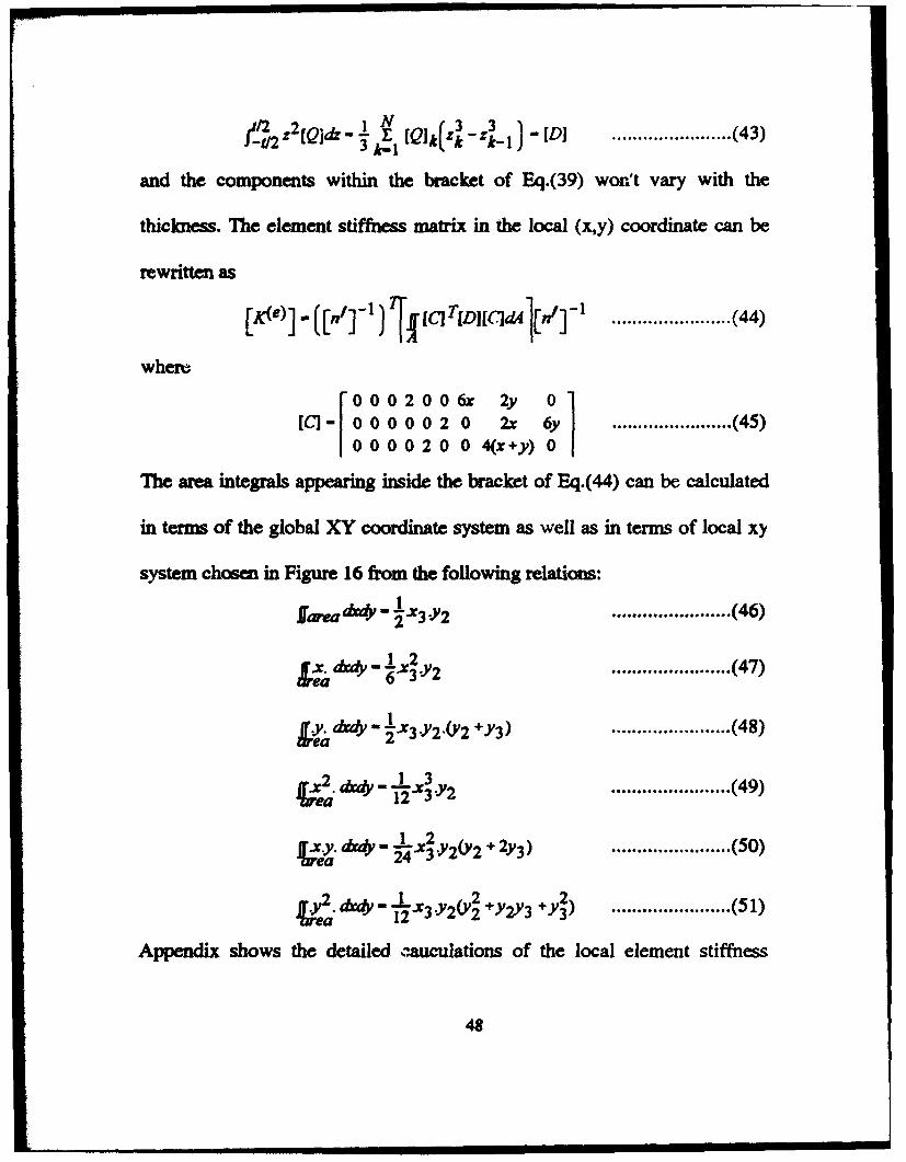
....................... (43)
and the components within the bracket of Eq.(39) won't vary with the
thickness. The element stiffness matrix in the local (x,y) coordinate can be
rewritten as
where
l CJ - o o o o o 2 o 2x 6y ....................... ( 4S) f 0 0 0 2 0 0 6x 2y 0 l 0 0 0 0 2 0 0 4(x + y) 0
The area integrals appearing inside the bracket of Eq.( 44) can be calculated
in terms of the global XY coordinate system as well as in terms of local xy
system chosen in Figure 16 from the following relations:
larea~ • f .x3 J'2 ...............•....... ( 46)
....................... ( 47)
....................... ( 48)
....................... ( 49)
....................... (50)
..................... .. (S 1)
Appendix shows the detailed ~uculations of the local element stiffness
48

matrix. Finally the element stiffness matrix from Eq.(44) in the global
coordinate system whose XY plane is assumed to be same as the local xy
plane) can be obtained from
[K](e) _ (pJ1fk<e)l(pJ
where the transformation matrix (p] is given by
10 000 000 0 0 lox mox 0 0 0 0 0 0 0 loy moy 0 0 0 0 0 0 0 0 0 1 0 0 0 0 0
(p)- 0 0 0 0 lox mox 0 0 0 9x9 0 0 0 0 loy moy 0 0 0
0 0 0 0 0 0 1 0 0 0 0 0 0 0 0 0 lox mox 0 0 0 0 0 0 0 loy moy
............. (52)
....................... (53)
where <lox, IDox) and Clov, IDov) represent the direction cosines of the lines ox
and oy respectively.
After each element stiffness matrix is calculated, it is assembled into
the global stiffness matrix. The resultant matrix equation becomes
[K][w]- [F]
where [F] is the force matrix.
....................... (54}
In order to compute stresses and strains, post-processing is
accomplished. After obtaining displacements, local strains are extracted
from the global displacements. To this end, the local coordinate, matrix [n'],
49
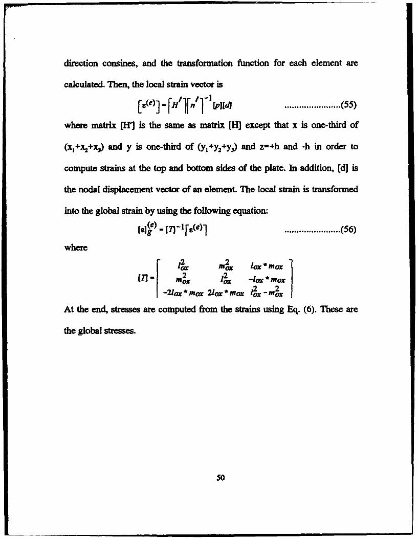
direction consines, and the transformation function for each element are
calculated. Then, the local strain vector is
...................•... (SS)
where matrix [H'] is the same as matrix [H] except that x is one-third of
compute strains at the top and bottom sides of the plate. In addition, [d) is
the nodal displacement vector of an element. The local strain is transformed
into the global strain by using the following equation:
[£]~) - [1]-1 r £(e)l ..•••••..••.........•.. {56)
where
r 2 2 l lox mox lox * mox
[1] • m~ I~ -lox* mox
-2/ox * mox 2/ox * mox l~x-m~
At the end, stresses are computed from the strains using Eq. (6). These are
the global stresses.
so
VL NUMERICAL RESULTS AND DISCUSSION
A. NUMERICAL RESULTS
In order to calculate the strain and stress for a laminated composite
plate with a quarter inch hole at the center and subjected to a pure bending
moment, a program named MFEM.M is written in Matlab. With an input for
material properties, plate dimensions, the applied bending moment, and the
failure load of the material, this program calculates the deflection, strain, and
failure stress for each element. Another program named DMTRX.M is also
written in Matlab which is capable to calculate the stiffness matrix [Q] for
four different kinds of laminae [00], [90o:J, [0°/900]12, and [( +4S0/-4S~Js·
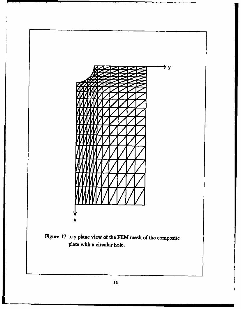
In this thesis, a laminated plate with a quarter inch hole at the center is
modeled with 214 nodes and 371 elements, which generates 642 by 642
stiffness matrix (642 dot) as shown in Figure 17. After calculations,
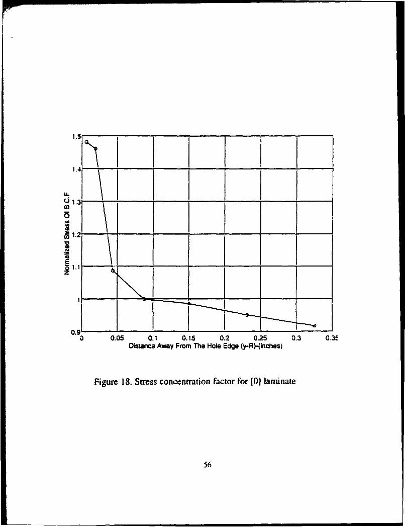
normalized stresses of stress concentration and the normalized failure
stresses v.s the distance away from the circular hole edge for [Oo:J24 and
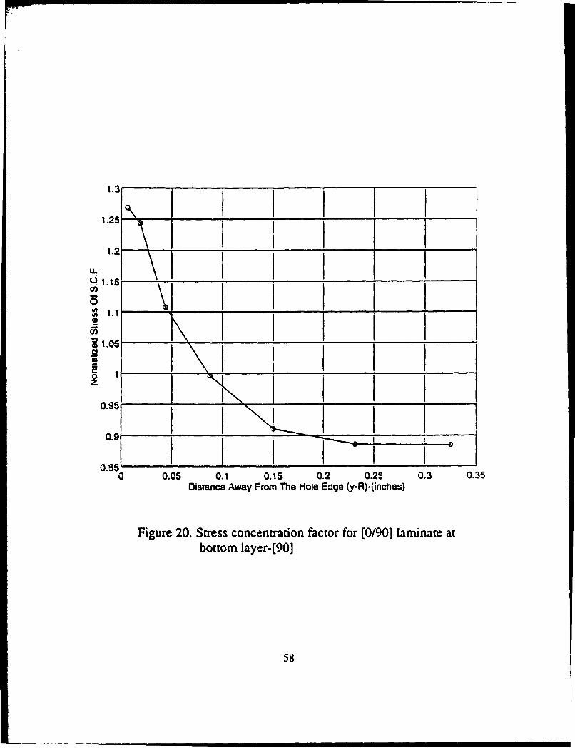
[0°/900]12 are plotted in Figure 18 through 23. As a result, the stress
concentration factor calculated from the F.E. analyses for the [0~24 laminate
is 1.47 and that for the [0°/90~12 is 1.27. Normalized failure stresses for the
Sl
[Oo:J24 laminate, the top [Oo:J layer and bottom [90o:J layer of the [0°/90o:l12
laminate are all close to one at the edge of the hole.
B. DISCUSSION
Whitney and Nuismer [Ref. 7] said that when the stress at a
characteristic distance, d,, away from the discontinuity would be equal to or
greater than the strength of the unnotched material, failure would occur. In
this current work, the constant value, d,, for the [Oo:J24 and (0°/90o:l12 laminae
is zero from the results. Thus, the failure criterion of Whitney and Nuismer
assumption is not suitable in this kind of graphite fiber/epoxy. Since it is of
great importance for design purpose to be able to predict the strength of a
composite tmder loading conditions prevailing in service, some failure
criteria like the maximum stress criterion and the Tsai-Hill failure criterion
are used in order to predict the failure and check the failure criteria.
1. Maximum Stress Criterion
This criterion tells that failure will occur when any one of stress
components is equal to or greater than its corresponding allowable strength.
Since the stress in the x-direction is the dominant stress in this current work,
failure will occur when
52

............. (57)
where XT 1 is the ultimate uniaxial tensile strength in the fiber direction ( in
this case, x-direction).
l. Tsai-Hill Criterion
According to the Tsai-Hill criterion, failure of an orthotropic lamina
will occur under a general stress state when
............. (58)
where X, Y, and S are the longitudinal tensile failure strength, the transverse
tensile failure strength, and the in-plane shear failure strength, respectively.
Figures 7 through 14 show that for this particular laminated composite
failure occurred almost simultaneously on both compressive and tensile
sides. From figures of normalized failure stresses, it is obvious that failure
occurred at the hole edge when the stresses at the hole edge were equal to
their cottesponding allowable strengths.
Stress concentration factors obtained from the experiments and
numerical analyses are nearly the same for both [Oo:J24 and [0°/90o:112
53

laminated plates. This result conflfDl that failure occurs when the maximum
stress at the edge of a hole is the same as the material strength.
54
y
X
Figure 17. x-y plane view of the FEM mesh of the composite plate with a circular hole.
ss
1.5
1.4
u. ~ 1.3 {/)
0 Cll Cll
! 0 1.2
i N
:.;: ca § 0 1.1 z
0.9 a
~ \ \ \ " ~
~~-- '---"""<!)
0.05 0.1 0.15 0.2 0.25 0.3 0.3~
Distance Away From The Hole Edge (y-R)-(indles)
Figure 18. Stress concentration factor for [0] laminate
56

1.3
1.25
1.2
u. q 1.15 (I)
0 :: 1.1 • ... c;; i 1.05 N = Cll
~ 0.95
0.9
I'.- I I \ I
I \ ' I i\.
\I ' ~ ~
I I
I I I I I I I
I I I I I I
I I I I I I I
~I I I
I I ~I I I I
I
I 0.85
0 0.05 0. 1 0. 15 0.2 0.25 0.3 Distance Away From The Hole Edge (y-R)-(inches)
I
--:>
0.35
Figure 19. Stress concentration factor for [0/90] laminate at top layer-[0]
57
1.3
1.25
1.2
u.. ~ 1.15 en 0 = 1.1 G)
a5 i 1.05 N
=j
i 1
0.95
0.9
0.95 0
' I I I I \ I I I \ I I I I \ I I I I I (!I
1\ I I I I I\ I I I I~ I I I I I~ I I I I I I I
~ I ! _ ...
I 0.05 0.1 0.15 0.2 0.25 0.3
Distance Away From The Hole Edge (y-A)-{inches)
Figure 20. Stress concentration factor for (0/90] laminate at bottom layer-(90]
58
' I I I
0.35

tn II)
1
0.95
0.9
! lr0.85
- 0.8 i N ;a as ~0.75
0.1
0.65
0.6 0
'i \ \ I
I
I \
\ ' "' ~ I
I - -I ,--- I ~
0.05 0. 1 0.15 0.2 }.25 0.3 0.35 Distance Away From The Hole Edge {)·n)·{inehes)
Figure 21. Stress distributions for [ o] laminate
59

1
0.95
"' 0.9 ! Ci5 ~0.85
~ i :S 0.8 Clll
I 0.75
0.7
0.65 0
\ \ ~
l\ ~ ~
r--..__1 I
";I
0.05 0. 1 0.15 0.2 0.25 0.3 Distance Away From The Hole Edge (y-R)·(inches)
Figure 22. Stress distributions for [0/90] laminate ar top layer-[0]
60
0.35

0.95
"' 0.9 "' ~ ._
ci5 ~0.85 ~
~ u. 'i ,... 0.8 :a e ~
0.75
0.7
1\ I I
I
I
0.65 0
\ '
\ ·I f\..
\ I I
I I I
' I I I
"' I I
'i--__ I I :1
I I 0.05 0.1 0.15 0.2 0.25 0.3 0.35
Distance Away From The Hole Edge (y-R)-(inches)
Figure 23. Stress distributions for [0/90] laminate at bottom layer-[90]
61

VIL CONCLUSIONS
In this thesis, a four-point bending test is used to investigate the failure
strain and failure stress for a graphite-fiber/epoxy composite of four different
laminated plates. From experimental results, composite elastic modulii are
obtained and the stress concentration factors due to a quarter inch hole
located at the center of the plate are calculated. Furthermore, a numerical
analysis using the finite element method is conducted to simulate the plate
under the same loading condition. By using both experimental and numerical
results, the characteristic distance de,, which determines failure based on the
Whitney and Nuismer theory, is examined. Finally, the maximum stress
criterion and the Tsai-Hill failure criterion is applied to check the failure of
composite. These failure criteria confum that failure occurs when the
dominant stress component of the laminated composite is equal to its
maximum allowable strength. From this work, it is also concluded that:
• the four-point bending test is a good way to investigate material
properties although it is a little more complicated to conduct than the
tensile test.
62

• The characteristic distance for the Whitney and Nuismer theory is
zero for the present composite material. Both the maximum stress
criterion and Tsai-Hill failure criterion are proper to predict the
failure for this material.
63
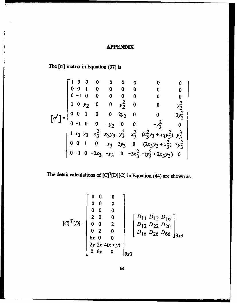
APPENDIX
The [n1 matrix in Equation (37) is
1 0 0 0 0 0 0 0 0 0 0 I 0 0 0 0 0 0 0 -1 0 0 0 0 0 0 0 1 0 Y2 0 0 y~ 0 0 y~
[n'J • 0 0 I 0 0 2y2 0 0 3y~ 0 -1 0 0 -y2 0 0 -y~ 0
1 XJ Y3 x2 2 x3 2 2 3 3 XJY3 Y3 3 (X3Y3 + X3Y3) YJ
0 0 I 0 x3 2y3 0 2 2 (2xJY3 + x3) 3Y3
0 -1 0 -2x3 -y3 0 2 2 -3x3 -(y3 + 2x3Y3) 0
The detail calculations of [C]T[D][C] in Equation ( 44) are shown as
0 0 0 0 0 0 0 0 0 2 0 0 Dll DJ2 DJ6]
[C]T[D] = 0 0 2 DI2 D22 D26 0 2 0 D16 D26 D66 3x3 6x0 0 2y 2x 4(x+ y) 0 6y 0 9x3
64

0 0 0 0 0 0 0 0 0
2Dn 2D12 2D16
[C]T(D] = 2Dt6 2D26 2D66
where
and
(C]T(Dl[C] =
2D 12 2D22 2D26
6xD11 6xD12 6xD16
41 42 43
6yD12 6yD22 6yD26
41 = 2yDII + 2xD12 + 4(x + y)D16
42 • 2yDI2 + 2%D22 + 4<x + y)D26
43 • 2yDI6 + 2xD26 + 4(x + y)D66
0 0 0 0 0 0 0 000 0 0 0 0 000 0 0 0 0 000 4Dtl 4D16 4Dt2 12xDtl 000 4Dt6 4D66 4D26 12xDt6
0 0 0 0 0 0
44 l2yDI2
as 12yD26
0 0 0 4Dl2 4D26 4D22 12xDt2 46 12yD22
o o o 12xv11 12xD16 12xD12 36x2Dll 47 36xyD12
000 A4 4s A6 47 4g 49
0 0 0 12yD12 l2yD26 l2yD22 36xyD12 a9 36y2D22
65

~8 = (4D22 + I6D26 + l6D66)x2 + (8D12 + l6Dt6>xY +(16D26 +32D66)xy+(4Dtl + 16Dt6 + I6D66)xy
Thus, the area integrals inside the bracket of Eq.( 44) can be obtained
0 0 0 0 0 0 0 0 0 000 0 0 0 0 0 0 0 0 0 0 0 0 0 0 0 0 0 0 A1 A2 A4 A1 Au At6
.[ [C]T(D][C]dA • 0 0 0 A2 AJ As Ag A12 A17 A 0 0 0 A4 As A6 A9 A13 Ats
0 0 0 A7 Ag A9 A 10 A 14 A 19
0 0 0 A11 A12 A13 A14 Ats A20
0 0 0 At6 A11 A18 A19 A20 A21
66
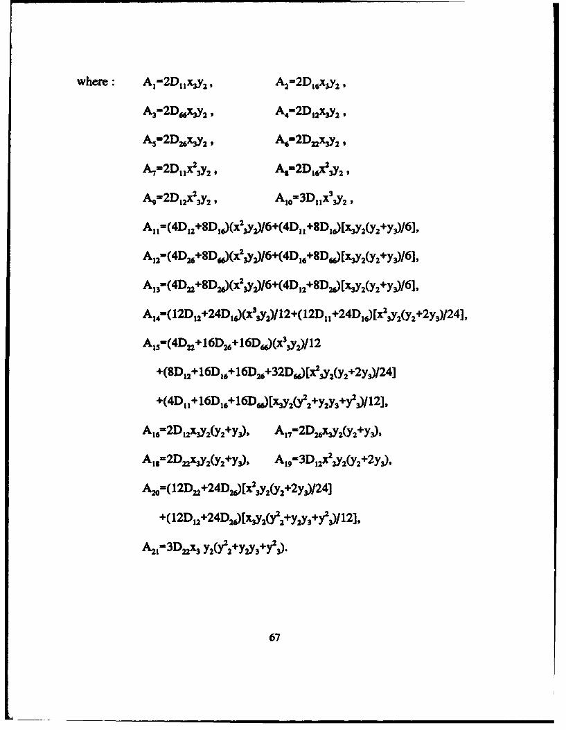
where: A1•2D11~y2 , Az=2D.,xvrl'
A3=2D66ltJ2 ' A.=2D12XJ2 •
A,•2Dl6~Yl , ~-2DnXJ2,
A,=2Dur 312 , A,=2Dt6r 312 ,
Ag=2Dt2x23Y2' Ato=3Dux3 312 '
A 11==(4D12+8D1J(x2,yJ/6+(4D11+8D1J[XJ2(y2+yJ/6],
A12==(4D16+8D~(r ,yJ/6+(4D16+8D~[XJ2(y2+yJ/6],
A13•( 4D11 +8DzJ(x2 ,yJ/6+( 4D12 +8DzJ[~y 2(y 2 +y J/6],
A 14=(12D12 +24D1J(x3 ,yJ/12+(12D11 +24D1J[x2 JY2(y2 +2y3)/24],
A15•(4D12+16D16+16D~(x3,yJ/12
+(8D12+16D16+16D16+32D~[r ,y2(y2+2yJ/24]
+(4D11+16D16+16D~[~2{f2+y:J3+y J/12],
At6=2Dt2XJ2(y2 +yJ,
A.,=2DnXJ2(y2 +yJ,
A 17•2D16XJ 2(y 2 +y J,
At9=3Dt2X2J2(y2 +2yJ,
Azo=( 12D12 +24DzJ[x2 ,y2(y2 +2yJ/24]
+(12D12+24DzJ[XJ2<f2+yz»3+f J/12],
Azt=3Dn~ Y2<f2+Y:J3+yl J.
67

LIST OF REFERENCES
[1) J.D. Sipes, Real Admiral, USCG Chairman, "SSC-360 Use of Fiber Rainforced Plastics in the Marine Industry", Ship Structure Committee, September 1990.
[2) A. G. H. Dietz, Engineering Laminates, Wiley (1949).
[3] N.J. Pagano, "Analysis ofThe Flecture Test ofBidiredtional Composites", J. Composite Materials, Vol. 1 (1967), p. 336.
[4) H. T. Haldl and S. W. Tsai, "Graphical Determination of Stitlhess and Strength of Composite Laminates", J. Composite Materials, Vol. 8 ( April 197 4), p. 160.
[5] Kirsch, G., VDI, VOL. 42, 1898.
[6] J. M. Whitney and R. J. Nuismer, "Stress Fracture Criteria for Laminated Composites Containing Stress Concentrations", J. Composite Materials, Vol. 8 (July 1974), p. 253.
[7] H. J. Konish and J. M. Whitney, "Approximate Stresses in an Orthotropic Plate Containing a Circular Hole", J. Composite Materials, Vol.9 ( Aprill975), p.157.
[8] N.J. Hoff and C. Muser, "Stress Concentration Factors for Cylindrically Orthotropic Plates", J. Composite Materials, Vol.16 (July 1982), p. 313.
(9) Fu-Kuo Chang and Kuo-Yen Chany, "A Progressive Damage Model for Laminated Composites Containing Stress Concentrations", J. Composite Materials, Vol. 21 (September 1987), p. 834.
68
(10] J. L. Bato~ K. J. Bathe, and L. W. Ho, "A Study of Three-Node Triangular Plate Bending Element", International Journal for Numerical Method in Engineering, IS, 1771-1812, 1980.
[11] J. L. Batoz, "An Explicit Formulation for an Efficient Triangular Plate Bending Element", International Journal for Numerical Method in Engineering, 18, 1077-1089, 1982.
[12] A. J. Fricker, "An Improved Three-Noded Triangular Element for Plate Bending", International Journal for Numerical Method in Engineering, 21, 105-114, 1985.
[13] S. W. Lee and J. C. Zhang, "A Six-Node Finite Element for Plate Bending", International Journal for Numerical Method in Engineering, 21, 131-143, 1985.
[14] J. L. Tocher, "Analysis of Plate Bending Using Triangular Elements", Ph.D Dissertation, University of Califonia, Berkeley, 1962.
69

INITIAL DISTRIBUTION LIST
1. Defense Technical Information Center Cameron Station Alexandria, VA 22304-6145
2. Library, Code 52 Naval Postgraduate School Monterey, CA 93943-5101
3. Professor Y. W. Kwon, Code ME'Kw Department of Mechanical Engineering Naval Postgraduate School Monterey, CA 93943-5000
4. Department Chair, Code MFJKk Department of Mechanical Engineering Naval Postgraduate School Monterey, CA 93943-5000
S. Dr. Shaio-Wen Wang Advanced Metallic & Ceramic Branch (6063) Aircraft Division Naval Air Warfare Center Warminster, PA 18974-0591
6. Dr. Roland Cochran Ploymer Composite Branch Aircraft Division Naval Air Warfare Center Warminster, PA 18974-0591
70
2
2
2
1
1
1
7. Mr. David Bonnani Naval Surface Warfare Center, Carderock Div. Code 1720.2 Bethesda, MD 20084-5000
8. Mr. Erik A. Rasmussen Naval Surface Warfare Center, Carderock Div. Code 1720.4 Bethesda, MD 20084-5000
9. Dr. Phillip B. Abraham Office ofNaval Research Mechanics Div. code332 800 North Quincy Street Arlingto~ VA22217-5000
10. Maj. Shih-Ting Yang 4F No. 9 Alley 3 Lane 80 Kai-Hsien 4th Rd. Kaohsiung, Taiwan R.O.C.
71
1
I
1
4