study of hard coating for aluminum alloys · wadc technical report 53-151 i study of hard coating...
TRANSCRIPT

WADC TECHNICAL REPORT 53-151
I STUDY OF HARD COATING FOR ALUMINUM ALLOYS
F. G. GILLIGCORNELL AERONAUTICAL LABORATORY, INC.
MAY 1953
Statement AApproved for Public Release
WRIGHT AIR DEVELOPMENT CENTER
SEP 18 1987 WPGIPT 4
Approved for public release; distribution unlimited. WEC* AL L1BPL%-,
FWPAFB, 0.AF.WP.B-O-16 JUL 53 250 w inoO OvUL2~ -
.*14 4' S O 87 8

NOTICES
a
When Government drawings, specifications, or other data are usedfor any purpose other than in connection with a definitely related Govern-ment procurement operation, the United States Government thereby in-cursnoresponsibility nor any obligation whatsoever; and the fact thatthe Government may have formulated, furnished, or in any way suppliedthe said drawings, specifications, or other data, is not to be regardedby implication or otherwise as in any manner licensing the holder orany other person or corporation,or conveying any rights or permissionto manufacture, use, or sell any patented invention that may in anywaybe related thereto.
The information furnished herewith is made available for studyuponthe understanding that the Government's proprietary interests inand relating thereto shall not be impaired. It is desired that the FudgeAdvocate (WCJ), Wright Air Development Center, Wright-PattersonAir Force Base, Ohio, be promptly notified of any apparent conflict be-tween the Government's proprietary interests and those of others.
400000000000

WADC TECHNICAL REPORT 53-151
STUDY OF HARD COATING FOR ALUMINUM ALLOYS
F. G. GilligCornell Aeronautical Laboratory, Inc.
May 1953
Materials LaboratoryContract No. AF 18(600)-98
RDO No. 615.14
Wright Air Development CenterAir Research and Development Command
United States Air ForceWright-Patterson Air Force Base, Ohio

FOREWOED
This report was pre pared by the Cornell Aeronautical Laboratory,Incorporated, Buffalo, New York, under USAF Contract No. Al' lg(600)-9S.The contrac~t was initiated under Research and Development Order No.,615-14i, "Aluminum Alloys" and was administered under the direction ofthe Materials Laboratory, Directorate of Research, Wright Air DevejlopnentCenter, with Mr. J. C. McGee acting as project engineer.
WADO TR 53-151

ABSTRACT
A study has been made of the effects of hard oxide coatings pro-duced by the MHC process on the properties of five wrought and twocast aluminum alloys. Coating thicknesses ranging from 0.0005 inch to0.005 inch were studied. Of the many properties that were studied, theabrasion resistance of the coatings and their effect on the fatiguestrength of the parent metal are the most significant. The abrasionresistance of the hard coatings is far in excess of that of coatingsproduced by standard anodizing treatments and has been demonstrated tobe equal to or better than that of thin cyanide coatings on steel. Inaddition to this, the coatings impart increased corrosion resistance tothe aluminum alloy surface. The abrasion resistance decreases with ex-posure to humidity and atmospheric conditions but proper post-treatments,other than boiling water which is used for sealing regular anodizedcoatings, will undoubtedly prevent this. The most serious shortcomingof the coatings has been found to* be their drastic lowering of the fatiguestrength of the coated alloy. Decreases as much as 65% in the base metalfatigue strength have been found. The effect is not proportional tocoating thickness and coatings of 0.001 inch produce practically the sameeffect as 0.005-inch coatings.
PUBLICATION REVIEW
This report has been reviewed and is approved.
FOR THE COMMANDING GENERALt
IA. E. SORTEColonel, USAFChief, Materials LaboratoryDirectorate of Research
WADC TR 53-151 i11

TABL 0p CONTW0TS
Page
INTRODUCTION. .. o .1 .. .
PATENT HISTORY 2. . . . . . • ... • .* • • . .. . 2LITERATURE SURVEY . . . . . . • • • . . . . . • . . . • . . 3
Electrical Requirements * . *** **** e 3Chemical Requirements. ....... . . .. .... . . 4Temperature Control.... .. .... ...... ... .4Other Irocessing Variables o * * • * * * • o o • 4
CHARACTERISTICS AND PROPERTIES OF HARD COATING . . . . . . . 5Nature o Film . ... . . . . . . . . . . . . . . .F ilThickness.. . . ... .. .•••* 5Alloys That May Be Coated. .. ....... ... .. 5Growth in Processing ... ..... .. ...... . 6Selective Coating . . . . . . . .. .. .0. . . . .. .. 6Adherence .. . . . . . . . . . .. . . . . . . . . . . . 6Abrasion and Wear Resistance . . . . . . . . . . . . . . 6Coefficient of Friction... . g... .... *... 7Hardness . * • .. .. a 7Ductility .t.,. . . • . . . . . . . . . . . . . ... . 7Endurance Strength . . . o . . . . . . . . . . . . . . . 7Heat Resistance . .. ... . . . . • . . . . . . 8Coefficient of Terma Expansion . ........ . . . 8CorrosionResistance . . .. • . . . .......... 8Electrical Conductivity ...... .......... 8RainErosion . . . . . . .. . . . . . . . . . . . . . . 8
Applications . . . . .. .. .. ... .. • • & • *• 9
TEST PROGRAM e .* . .* * * * . . * * * * * * o * * * * a 10TEST PROCEDIJRSAETRESULTS •.• . . o . . .. .. •. * . . 12
Coating Thickness - Time Relationships . . .. .. . . 12Growth Daring Coating . . . & . .. . .0 . .. . .* . . . 12Color of Coatings. s.. ...... . . • • • • • • • • 13Coating Defects and Deficiencies • * • • • • • • * • • • 13
Minimum Radii for Co~ting . . . . . .. . . . ... *. 14Structure of Coating . . ..... .. *...... 14Throwing Power e . .* . .* . ..o. .*.. *. 16Abrasion Tests .... • • • • • • ...... * • e * • 17Dielectric Strength o . . . *'--re" "" 18Effect of Coating on Fatigu Strength ....... 19Bend Tests . * * . .. .. ....... . . . . . . . 22Flame Tests.. . .. e............... 0& 0& 00 22
Heat Tests . .. . . .. * . . . . . . . . .* . .& .... 23Thermal Conductivity . . ... . ... ......a 24Effect of Coating on Tensile Strength o . . . . . . . . . 24Compression Tests . .. ... 0. • • . . •. . . . . . 26Rain Erosion ..... * * * * o * * o o * . 26
WADO TR 53-151 iv

TABLM OF MO0UMS (CONT'D)
Page
Effect of Gunfire Penetration .... ....... .. . 27Coefficient of Expansion ................ 28Thermal Shock . . . . , * . . . & 0 . . . . . . 29Corrosion Resistance . • • 0 • • ............ 29
DISCUSSION .. .. . .. . o . . . . . . ..... 31
COMCLUSIONS •. . . . . . . . . . . . . . . . . . . . . . . . 32BIBLIOGRAPHY . o. . . . . ... .. .. .. .. .. .. ... 33ACK1!OWI;DGT'JENT..... . . . . . . . . . . . . . . . . . .. 35
WADCO TR 53-151 v

LIST OF TABLES
Table Page
I. Bend Tests on 61S-T6 - 0.501-Inch Thick . . .... 36II. Bend Tests on XA78S-T6 - O.064-Inch Thick . . . . . 37
III. Bend Tests on 24S-T3 Bare - 0.051-Inch Thick • . 38IV. Bend Tests on 2bS-T4 Alclad - 0.051-Inch Thick • • 39
V. Bend Tests on 75S-T6 - 0.051-Inch Thick ...... hOVI. Flane Tests . . ....... *1
VII. Tensile Tests on Hard Coated 61S - O.032--Inch Thick 42VIII. Tensile Tests on Hard Coated 61S - 0.050-Inch Thick 03
IX. Tensile Tests on Hard Coated 61S - 0.081-Inch Thick 44X. Tensile Tests on Hard Coated XA78S-T6 . . ..... 45
XI. Tensile Tests on Hard Coated 24S-T3.. .0.... 46XII. Tensile Tests on Hard Coated 24S-T4 Alclad • • • 47
XIII. Tensile Tests on Hard Coated 75S-T6 . • • ..... 48XIV. Tensile Tests on Hard Coated 356 Alloy . . . . . . 49
XV. Tensile Tests on Hard Coated 220 Alloy . . . . . . 50XVI. Compression Tests on Hard Coated 61S- 0.050-InchT h i c k . * *. * *.e. * * *.e e.e.* e.a.*. . . . * &. .. e . 5 1
XVII. Compression Tests on Hard Coated 61S - 0.032-InchThick ... . . 52
XVIII. Compression Tests on Hard Coated XA72S-T6 . . .0. . 53XIX. Compression Tests on Hard Coated 24S-T3 . . . 0 . 0 54
XX. Compression Tests on Hard Coated 21IiS-T4 Alclad . . 55XXI. Compression Tests on Hard Coated 75S-T6 * • . • • 56
XXII. Compression Tests on Hard Coated 356 Alloy .. .. 57XXIII. Compression Tests on Hard Coated 220 Alloy . . . . 58
XXIV. Coefficients of Expansion . .... . . . . . . . 59XXV. Abrasion Resistance After Thermal Shock . . . . . . 60
XXVI. Results of Salt Spray Tests After Seven MonthsExposure ...... . . . . ......... .e 61
LIST OFILLUSTRATIOIS
Figure
1. Graph Comparing Wear Resistance of MHC Coating WithThat of Various Other Materials & Coatings .... 62
2. S-17 Curve Illustrating Marked Drop in EnduranceLimit of Hard Coated Aluminum . . . ...... 62
3. Thickness of Coating vs. Time Curves .6...4. Growth of Coating vs. Thickness Curves . . . . . .5. Crazing of Coating on Commercially Pure Aluminum . 65
WADC R53-151 Vi

LIST OF ILLUSTRATIONS (CONT'D)
Figure
6. Blisters on 24S Alclad Sheet . . ......... 667. Roughness of Coating on 24S Bare Alloy ..... . 678. Corner Defect for Various Thicknesses of Coating . 659. Cracks in Coating on Small Radii . . . . .... 69
10. Structure of Coating on 61S Alloy as it AppearsUnder Polarized Light .. . .a *• • • 70
11. Structure of Coating on 24S Alloy as ObservedWhen Illuminated by White Light *........ 71
12. Layer Structure of Coating on 24S as Brou~t Outby Polarized Light . * * * *. .# . .* .* * . . 71
13. Structure of the Coating on 356 Casting Alloy . . 7214. Outdoor Exposure Rack Used for Weathering Abrasion
Test Specimens . ., . . ......... ... . 7315. Abrasion Resistance vs. Thickness of Coating on24S Alclad . . . . . . . .. o . . . ... . . . . . 74
16. Abrasion Resistance vs. Thickness of Coating on24S Bare . *... . . . . .. .* . . .* . . .. . * 75
17. Abrasion Resistance vs. Thickness of Coating on75S Sheet . . . . . . . . . . . . . . . . . . . . 76
18. Abrasion Resistance vs. ThickneSs of Coating onXA78S Sheet * * # * * o * .. ... .. .. .. . . 7719. Abrasion Resistance vs. Thickness of Coating on
61S Sheet * # • * • a . .. *. . .. . . . . . . . 7520. Abrasion Resistance vs. Thickness of Coating on
220 Alloy • • • • .0. . . . .*.1 . . . . . . . a 4 7921. Abrasion Resistance vs. Thickness of Coating on
356 Alloy . . . . . . . . . . . . . . . . . . . s022. Dielectric Strength of 24S Bare and Alciad . . . . 8123. Dielectric Strength of 75S and XA78S Alloys . . o 5224. Dielectric Strength of 61S and 356 Alloys . . . • 825. Dielectric Strength of 220 Casting Alloy . . . . .26, Effect of Coating on Fatigue Strength of 24S
Alclad . .C o F Srg o 2.. 5. . . 927. Effect of Coating on Fatigue Strength of 4S Bare.28. Effect of Coating on Fatigue Strength of 75S
Alloy *... 0.0 & . . . . .* . . • * . 9729. Effect of Coating on Fatigue Strength of 6A73S
Alloy 0.032-InchThk. . . . . . . . . . . .* 9030. Effect of Coating on Fatigue Strength of 75Sc K 1clad . . . . . . . . . . .. . . S31., Effect of Coating on Fatig~ue Str-engih'of 6S She~et* g
0.032-Inch Thick.. .... . ..... . . 9132. Effect of Coating on Fatigue Strength of 61S SheetO. O51-!nch Thick .... . . .. .. . . . . .. 933. Effect of Coating on Fatigue Strength of 61S Sheet
O.080-Inch Thick ............. . . . 92
WADC;TR 53-151 Vii
LIST (1' ILLUSMM0NS (OONT'D)
Figure
34. Effect of Coating on Fatigue Strength of 61S Spec-imens When Coated on Only One-Half Their Length . . 93
35. Location of Failures in 61S Fatigue SpecimensCoated for Half Their Length e e * • •. •.. .• 95
36. Effect of Coating on Fatigue Strength of 61S Spec-imens Coated on One Side Onlyo . . .. . .. . . 0. 96
37. Effect of Coating on Fatigue Strength of 220 Alloy. 9738. Effect of Coating on Fatigue Strength of 356 Alloy. 9939. Bend Tests Showing Flaking Type of Coating Failure. 9940. Bend Tests Showing Spalling Type of Coating
Failure . * a e * o * & * o o o * # o o o 0 . . 0 0 10041. Bend Test Showing Failure of Coating by Hairline
Spalling .... . .o . . . ..o . . .. . . .o 10142. Flame Tests Showing "End-Poirrt" Condition . . . . . 10343. Heat Test Curves for 61S, XA78S, 24s Bare and 24S
Alciad . . . . .. . . • * o o * * 0 . • 0 0 • 0444. Heat Test Curves for 75s, 356, and 220 Alloys . . . 10545. Thermal Conductivity Curves for 61S, XA78S, 24S
Bare, and 2.4S Alclad • e . .• 0 • 0 0 • • 0 • * 0 10646. Thermal Conductivity Curve for 75S Sheet . o o o o 10747a. Rain Erosion Specimens After Five-Minute &lposure
in Test Appwratus . * & o e & . a * e . 0 . . . 0 10847b. Rain Erosion Specimens After Five-Minute AJzosure
-in Test Apparatus . 0 0 0 . 0 . . 0 a . 0 0 a . 109148a, Rain Eroaion Specimens at End of Test Periods. . 10481. Rain Erosion Specimens at End of Test Periods. . U149. Gunfire Penetration Tests . . . . . . . . . . .o3
WADC TR 53-151 viii

INT•OPDUCTION
The light weight per unit volume of aluminum is desirable in manyapolications where its wear resistance prohibits- its use. Aluminummight also be desirable in some applications because of the ease offabrication and its availability in a wide range of extruded sections.On the other hand, the weight or susceptibility to corrosion of casehardened steel make its use undesirable for the same applications.
A solution to this dilemma evidently lies in a method for pro-ducing on aluminum a surface which is comparable to that of case hard-ened steel. During the past few years, several processes for the pro-duction of hard oxide films on aluminum and its alloys of greaterthicknesses than can be formed by the regular anodizing processes havemade their appearance. These processes were welcomed by many designersas the solution to their problems. Because of the newness of the pro-cesses, little data other than the effect of the coating on wear resist-ance were readily available.
With many new processes the too eager acceptance and over appli-cation by designers had led to an early misuse and resultant adversecriticism which has been difficult to overcome. This has resulted ina general reluctance on the part of others to make use of these pro-cesses even for those applications to which they are ideally suited.In order to prevent this from occurring and to make available as muchdata on the properties of the hard coatings as possible in a relativelyshort time after their introduction, the Wright Air Development Centersponsored this test program under contract number AF 18(600)-98 toinvestigate the effects of hard coatings on the properties of aluminumalloys and to obtain design data which may be applicable to aircraftand guided missiles. The results of this program are presented hereintogether with most of the other data that have been published regardingthe processes for producing hard oxide films on aluminum and its alloys.
WAJC T 53-151 1

PATENT HISTORY
The processes for producing a hard, wear and corrosion resistantfilm on aluminum by treating it electrochemically date back to theoriginal development of the chromic acid anodizing process by Bengoughand Stuart in 1924 (1, 2).* Since that time a number of variationsof the process have evolved and some patents issued. A patent historyand digest for the anodizing process has been assembled by G. H. Hogaboonmhich covers the state of the art up to 1945 (3). Most of these patentshave expired and only a few are still in effect. The general featuresof these processes are similar and all aim toward the production of anadherent oxide on the surface of aluminum. The processes generallyemploy direct current and have the work piece as the anode. A fewutilize alternating current and the coating forms only during that partof the cycle that the work piece is the anode. A number of electrolyteshave been suggested but only a few have gained wide popularity: Chromicacid and sulphuric acid solutions for producing the commercial wearresistant films and oxalic and other acid solutions for use in the manu-facture of electrolytic condensers. By controlling the concentrationand composition of the electrolyte, and voltage conditions, coatingsof various thicknesses and of varying porosities can be obtained. Thethickness range is, however, limited to coatings below 0.001 inch, theusual commercially produced thickness lying in the range of 0.0001 to0.0008 inch.
Within the past two years three processes have been developed forproducing thick oxide coatings on aluminum which range up to 0.005 inchand greater in thickness. These processes are: The MHC (Martin HardCoat) process, the Alumilite Hard Coating process, and the Hardas pro-cess. The first of these processes was developed at the Glenn L.Martin Company, Baltimore, Maryland. The patent application (4) hassince been acquired by the Aluminum Company of America who developedthe Alumilite Hard Coating process. The latter process has not re-ceived any wide publicity to date. No specific patent application hasbeen made for this process but it is in general similar to the MHC pro-cess and is therefore covered by that patent application. It is alsoclaimed that some of the features are covered by existing patents forthe Alumilite process of sulphuric acid anodizing. The Aluminum Companyof America plans to grant royalty free licenses to prospective users ofboth the MHC and Alumilite Hard Coating processes. The Hardas processis owned by Hard Aluminum Surfaces Ltd., Glasgow, Scotland.
*See bibliography.
WAVO T 53-151 2

LITERATURE SURVEY
All of the processes for producing a hard coating on aluminum andits alloys are electrochemical in nature and result in the fomiationof a thick layer of aluminum oxide on the surface of the article beingtreated. The main difference between normal anodizing and these pro-cesses is that they are performed at higher current densities and theprocess is carried out at low temperatures with considerable agitation.The exact processing details of the MHC and Hard Alumilite processeshave not been released for publication but a number of articles haveappeared "in periodicals regarding the relative merits and propertiesof the MHC films (5-9). A paper was presented in February, 1952 byW. J. Campbell before the Institute of Metal Finishing in Birmingham,England relative to the Hardas process and the production of thick oxidefilms in general (10). Campbell states that the thick oxide films maybe produced under, a range of conditions and gives data for the variables,as follows:*
Electrical Requirements
Current density may vary from 0.1 ampere per square inch in anoxalic acid electrolyte to 3 amperes per square inch in sulphuric acid.In the Hardas process both direct and alternating currents are used:the proportion and actual voltages depending largely upon the materialbeing treated and the desired thickness of the oxide film, the requiredvoltage increasing as the film becomes thicker in order to maintain thecurrent density at a constant value. Light alloys high in zinc may betreated with direct current only at 0.5 ampere per square inch in sul-phuric acid at a starting voltage of 20 volts, rising to 50 volts in15 minutes, producing a film 0.003 inch thick. An additional processis necessary with these alloys to improve the adhesion of the film tothe metal. Die cast 13% silicon alloy is treated in sulphuric acidwith a current density of 1.0 ampere per square inch and a large A.C.component. A 15% copper alloy has been successfully treated by applyingA.C. alone for a short period to form a film and then finishing withsuitably combined current s.
Proportions of A.C. and D.C. vary according to the alloy and, inmost cases, it is necessary to preserve a constant voltage ratio betweenthem during the whole processing period while the voltage is being raisedto maintain constant current density, Several reasons are advanced forthe need of a high current density. Some alloys require it to overcome
*It is to be noted that certain of the features enumerated in the par-agraphs describing the Hardas processing are the basis of the HardAluminum Surfaces Ltd. patent applications.
WADe TR 53-151 3

passivity; also shorter time cycles may be used. The shorter the pro-cessing schedule the harder the surface that is produced. The electro-lyte has a solvent action on the coating and the porosity of the coatingincreases the longer this reaction is allowed to proceed.
As may be inferred from the above, a relatively involved powersetup is required for the Hardas process whic~i uses a combination ofA.C. and D.C. currents. (For comparison, the MHC process and the HardAlumilite process require the use of D.C. current only.)
Chemical Requirements
Both oxalic acid and sulphuric acid can be used as electrolytes.Mixtures of the two have also been successful. The film produced byoxalic acid is generally smoother than that produced in sulphuric acidbaths but the latter allows a higher production rate. Acid concentra-tion is not critical; in fact, hard surfaces have been obtained insulphuric acid baths ranging from 1% to 70%.
Temperature Control
Because of the high current densities involved and the tendencytoward burning, the electrolyte must be maintained at a low temper-ature. The thicker the film the greater the amount of refrigerationthat is needed. As the film builds up, its electrical resistanceincreases and the voltage must be increased to maintain the currentdensity; this results in greater heat input and requires more refrig-eration to maintain the electrolyte at a temperature which will preventburning. Heat transfer is also increased by agitation of the solutionand movement of the work rod. Optimum temperatures for sulphuric acidelectrolytes seem to lie between -4oC and +4°C. As the temperature ofthe electrolyte increases above the upper limit, the film becomes pro-gressively softer and there is apparently no definite line of demarca-tion between "hard" anodizing and "normal" anodizing.
Other Processing Variables
The process must be modified according to the aluminum alloytreated. It is preferable to process only one alloy at a time. Segre-gation in castings between heavy and light sections sometimes causesroughness and this defect has even been encountered in extrusionsbecause of inhomogeneity in the extrusion billet. A thick piece ofmetal may have to be treated one way while a thin sheet of the samealloy may require modification of the process. This is due to the dif-ference in heat dissipating properties of thick and thin sections.
WAOC TR 53-151 -
CHARACTERISTICS AND PROPERTIES OF HARD COATINIGS
Nature of Film
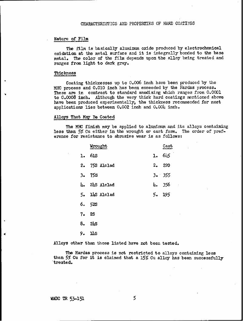
The film is basically aluminum oxide prodiced by electrochemicaloxidation at the metal surface and it is integrally bonded to the basemetal. The color of the film depends upon the alloy being treated andranges from light to dark gray.
Thickness
Coating thicknesses up to 0.006 inch have been produced by theMHC process and 0.010 inch has been exceeded by the Hardas process.These are in contrast to standard anodizing which ranges from 0.0001to 0.0008 inch. Although the very thick hard coatings mentioned abovehave been produced experimentally, the thickness recommended for mostapplications lies between 0.002 inch and 0.004 inch.
Alloys That May Be Coated
The MHC finish may be applied to aluminum and its alloys containingless than 5% Cu either in the wrought or cast form. The order of pref-erence for resistance to abrasive wear is as follows:
Wrought Cast
1. 61s 1. 6h5
2. 75S Alclad 2. 220
3. 75S 3. 355
4. 24s Alclad 4. 356
5. 14S Alclad 5. 195
6. 52s
7. 2S
8. 24S
9. 34S
Alloys other than those listed have not been tested.
The Hardas process is not restricted to alloys containing lessthan 5% Cu for it is claimed that a 15% Cu alloy has been successfullytreated.
WADC TR 53-151 5

Growth in Processing
The growth in processing is probably dependent upon the particularconditions used. Values reported for the MHC process are as follows:
Film Thickness In. Growth In.
0.0004 0.00035
0.ooo8 0.00075
0.0020 0.0011
0.0044 0.0015
Parts must be machined undersize to allow for this growth in pro-cessing. It may be possible to reclaim some worn parts by applyingthe hard coating.
Selective Coating
Coatings are normally applied only to finished parts. Surfacefinish is generally maintained during the coating process. Whenspecific areas are to be hard coated, and the rest of the part anodized,the entire part is first anodized and then properly masked before hardcoating. Care must be taken in the masking operation as the flow pat-terns set up in the electrolyte and the insulating properties of thestop-off material may result in local burning of the hard coating.
Adherence
The film is strongly adherent to most alloys, especially thosecontaining magnesium. The poorest adherence is shown with the alloyscontaining zinc. On right angle bends over a 3/h inch rod, a 0.002 inchMHC coating will spall off on the compression side and forms fine crackson the tension side. The coating has fair impact resistance althoughit is easily dented and slightly chipped when struck by a hammer re-peatedly.
Abrasion and Wear Resistance
The best abrasion resistant coatings are produced on smooth sur-faces. Wear resistance of the MHC coatings, as measured by a TaberAbraser, is better than case hardened steel and hard chrome plate.The comparison is illustrated by the data shown graphically in Figure1. An added advantage of the thick oxide coatings is that the wearis equally slight on whatever other metal rubs against the film. Thewear resistance of a Hardas film was dramatically demonstrated byturning an aluminum rod with a lathe tool made from hard surfaced high
WADC T53-151 6

strength aluminm alloy. The tool showed no wear and did not collapse
until an attempt was made to use it on hard bronze.
Coefficient of Friction
Preliminary tests have indicated that the hard coatings have alower coefficient of friction than the untreated metal. Sliding wearýtests indicate that maximum wear resistance can be obtained with alubricant of molybdenum sulfide or graphitic grease. The film possessesgood oil retention qualities even though the finest colloidal graphititwill not pass into the pores. The coefficient of friction will of boursedepend upon the prior surface finish of the part and may be farther re-duced by lapping or honing the hard film.
A Hardas film finished to about three microinches gave a coeffi-cient of friction of 0.11. Breakdown of the hard films is generallycaused by disintegration of the oxide layer brought about by excessivefrictional heat. As the film is a good thermal insulator, the heatremains localized. Therefore, two hard coated surfaces should not beused where they rub together unless the relative motion is slow orintermittent.
Hardness
Accurate values have not been determined by indentation methodsbut the coating may be considered as approximately file hard. Thehard surface will scratch window glass. For use where the film is soloaded as not to cause its collapse,. the hardness may be consideredas approximately that of nitrided steel. The film disintegrates underthe action of point loading and heat. Drilling can be carried outfairly easily after a part has been processed.o The film may also befiled away mith a coarse file. A smooth file has little effect onflat surfaces.
Ductility
The coating itself is brittle and cracks easily but remains stronglybonded to the base metal. The coating process causes some loss of ductil-ity in the tensile test of coated 0.060 inch 75S-T6 sheet. The tensileand yield strengths are only slightly reduced and this is in part due tothe decrease in cross section of the base metal.
Endurance Strength
Coating produces a marked decrease in the endurance strength of75S-T6 aluminum alloy, as shown in Figure 2.
WADC TR 53-151 7
Heat Resistance
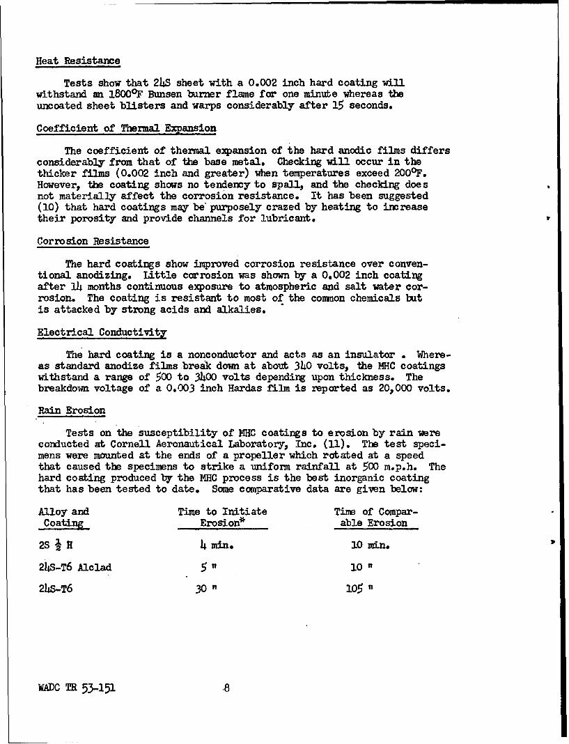
Tests show that 2hS sheet with a 0.002 inch hard coating willwithstand an 1800°F Bunsen burner flame for one minube whereas theuncoated sheet blisters and warps considerably after 15 seconds.
Coefficient of Thermal Expansion
The coefficient of thermal expansion of the hard anodic films differsconsiderably from that of the base metal. Checking will occur in thethicker films (0.002 inch and greater) when temperatures exceed 200 0F.However, the coating shows no tendency to spall, and the checking doe snot materially affect the corrosion resistance. It has been suggested(10) that hard coatings may be purposely crazed by heating to increasetheir porosity and provide channels for lubricant.
Corrosion Resistance
The hard coatings show improved corrosion resistance over conven-tional anodizing. Little corrosion was shown by a 0.002 inch coatingafter 14 months continuous exposure to atmospheric and salt water cor-rosion. The coating is resistant to most of the common chemicals batis attacked by strong acids and alkalies.
Electrical Conductivity
The hard coating is a nonconductor and acts as an insulator . Where-as standard anodize films break down at about 340 volts, the MHC coatingswithstand a range of 500 to 3400 volts depending upon thickness. Thebreakdown voltage of a 0.003 inch Hardas film is reported as 20,000 volts.
Rain Erosion
Tests on the susceptibility of MHC coatings to erosion by rain wereconducted at Cornell Aeronautical Laboratory, Inc. (11). The test speci-mens were mounted at the ends of a propeller which rotated at a speedthat caused the specimens to strike a uniform rainfall at 500 m.p.h. Thehard coating produced by the MHC process is the best inorganic coatingthat has been tested to date. Some comparative data are given below:
Alloy and Time to Initiate Time of Compar-
Coating Erosion* able Erosion
2SIH 4rmin. 10 m.in
24S-T6 Alclad 5 " 10 "
24S-T6 30 " 105 "
WADC T 53-151 8
Alloy and Time to Initiate Time of Compar-
Coating Erosion* able Erosion
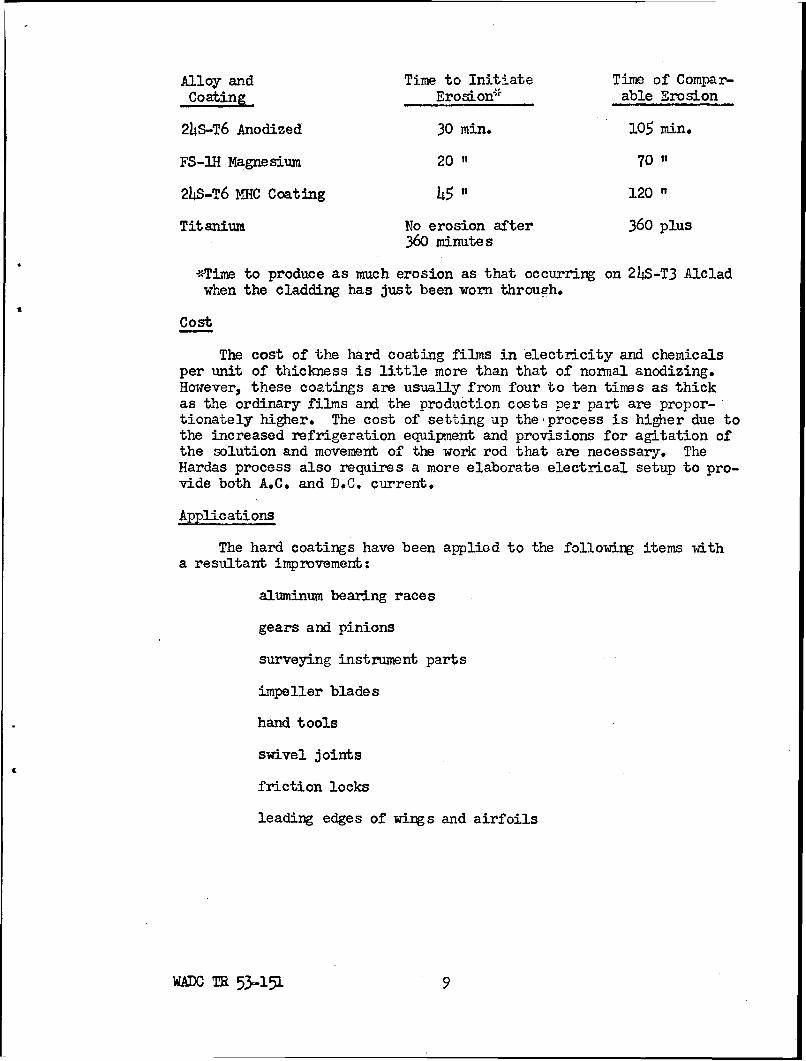
24S-T6 Anodized 30 min. 105 min.
FS-IH Magnesium 20 " 70 "
24S-T6 MHC Coating 45 " 120 "
Titanium No erosion after 360 plus360 minutes
*Time to produce as much erosion as that occurring on 24S-T3 Alcladwhen the cladding has just been worn through.
Cost
The cost of the hard coating films in electricity and chemicalsper unit of thickness is little more than that of normal anodizing.However, these coatings are usually from four to ten times as thickas the ordinary films and the production costs per part are propor-tionately higher. The cost of setting up the process is higher due tothe increased refrigeration equipment and provisions for agitation ofthe solution and movement of the work rod that are necessary. TheHardas process also requires a more elaborate electrical setup to pro-vide both A.C. and D.C. current.
Applications
The hard coatings have been applied to the following items witha resultant improvement:
aluminum bearing races
gears and pinions
surveying instrument parts
impeller blades
hand tools
swivel joints
friction locks
leading edges of wings and airfoils
WADC TR0 53151 9

cams
aluminum jigs and fixtures
pistons
leg braces for paraplegics
jack screw threads
airplane door thresholds and walkways
carburetor deck plates
aircraft door hinges
Many direct substitutes of hard coated aluminum for steel in movingparts and static surfaces subjected to scuffing and other forms ofwear have been made by the Glenn L. Martin Company in their aircraft.
TEST PROGRAM
All of the hard oxide coatings that were tested during this projectwere applied by the MHC (Martin Hard Coat) Process. The work was doneat Cornell Aeronautical Laboratory, Inc. in an experimental tank contain-ing 65 gallons of solution. Processing conditions were as specified inthe Aluminum Company of America Bulletin No. 6 for Alcoa Finishes. Pre-cleaning was done in hot 5% caustic followed by treatment in "DO" Deox-idizer, a proprietary compound produced by the Cowles Chemical Company.
The following alloys were included in the investigation:
61S-T6
XA78S-T6
Bare 24S-T4
Alclad 24S-Tl
Bare 75S-T6
Cast 356-T6
Cast 220-T4
WADC TR 53-151 10

Coatings were applied on these alloys in thicknesses rangingbetween 0.0005 and 0.005 inch in thickness. The following propertiesof the coating and its effect on parent metal properties were studied:
Coating Thickness Time Relationships
Growth During Processing
Color of Coating
Coating Defects and Deficiencies
CrazingBlistersSurface RoughnessCorner Defect
Minimum Radii for Coating
Structure
Throwing Power
Abrasion Resistance
As-coatedAfter Exposure to Atmospheric ConditionsAfter Exposure to High Humidity
Dielectric Strength
Fatigue Strength
Bend Radii
Flame Resistance
Heat Resistance
Thermal Conductivity
Tensile Strength
Compression Strength
Rain Erosion
Gunfire Penetration
Thermal Expansion
WADC TR53-151 11

Corrosion Resistance
AtmosphericHumiditySalt Spray
These tests are fully described and the results presented in thenext sections of this report.
TEST PROCEDURES AND RESULTS
Coating Thickness - Time Relationships
In order to be able to predict with a reasonable degree of assurancethat a definite thickness of coating could be applied to a given alloy,it was first necessary to coat a series of test pieces for given lengthsof time and determine the thicknesses of the resulting coatings. Spec-imens of each alloy were coated for 40, 100," and 200 minutes and thecoatings measured microscopically (12, 13). Thickness vs. time curveswere plotted and these were used to apply given thicknesses of coatingson the specimens to be tested. Small pieces were also eut from the firstseries of test specimens and the coating thicknesses measured to providemore points and better establish the curves. The thickness of coatingvs. time curves are shown in Figure 3. It should be noted that thecurrent density could not be maintained for the 61S alloy with the 130volt generator which was used and this curve falls off far this reason.The 75S and XA78S alloys allow the coating to build up faster than the24S bare or 11c1ad. Actual thicknesses close to 0.009 inch were measuredfor the 75S and XA78S alloys. However, in these greater thicknesses, theedges tend to crumble and the surface layers are soft and powdery.
The curves as presented in Figure 3 apply only for the coating con-ditions specified in the Aluminum Company of America Bulletin No. 6 forAlcoa Finishes and deviations from these conditions will influence therate of coating and the maximum thickness obtainable.
Growth During Coating
The test specimens were accurately measured before and after coatingand the increase in thickness obtained for the various coating thicknesseswhich were measured metallographically. These data are plotted for thevarious alloys in Figure 4. It can be seen that all of the alloys showa uniform growth equal to approximately one-half the thickness of thecoating. This is tobe expected inasmuch as the basic constituent of allof the coatings is the same.
WADC TR53-151 12

Color of Coatings
The color of the coating depends both upon the alloy and upon thecoating thickness. 61S and 24S bare and Alclad have a light tan orgray color for a 0.O005-inch coating which gradually darkens to a jetblack as 0.003 inch is exceeded. The 75S and XA78S alloys have a lighttan color when coated with 0.0005 inch which turns to jet black for0.001 inch. The color then changes to a blue-gray which gets progres-sively lighter until at 0.009 inch the coating is almost white. On99.99% purity aluminum, the coating is colorless for the 0.001-inchthickness and slowly changes to a light brown as the thickness is in-creased to 0.005 inch. The color of the coatings is also dependent uponthe amount and type of alloy previously processed in the bath.
Coating Defects and Deficiencies
Crazing - or fine hairline cracks are present on the surface of thecoating when it is withdrawn from the processing bath. These cracksoccur during the processing cycle. As the coating warms up to roomtemperature, the number of cracks in the coating increases. If a coatedpiece is held near the ear, the cracking of the coating is audible. Thecracks are not as clearly visible on the alloys that form dark gray andblack coatings as they are on the transparent coatings formed on purealuminum. Figure 5 shows the crazed pattern that developed on a pieceof commercially pure aluminum.
Blisters - have been encountered in some of the 24S Alclad specimens.Their occurrence seems to be directly related to the ratio of the thick-ness of the coating to the thickness of the cladding. When the thicknessof the hard coating exceeds the thickness of the cladding, blistering isliable to occur. Figure 6 shows a 0.O04-inch coating on 0.031-inch sheetand on 0.082-inch sheet. The 0.031-inch sheet is badly blistered whilethe 0.082-inch sheet is uniformly coated. The cladding on the two sheetswas 0.0022 and 0.0056 inch respectively. This defect seems to be asso-ciated with particular lots of material as other lots of this alloy havebeen processed which coated satisfactorily.
Surface Roughness - is increased when the 24S bare alloy is processed.It is not as pronounced in the case of sheet stock as it is in bar stock.The coating process seems to accentuate the macrostructure. However, thisroughness can be eliminated if the part is made slightly oversize (allow-ing for increase in dimensions due to coating) and lapped down to thefinish dimension after coating. Figure 7 shows a spool for a hydraulicvalve before and after applying a 0.003-inch coating. The part was sub-sequently lapped and placed in an experimental valve which has outperformedthe previously used stainless steel spools in all respects.
WAIDC M53-151. 13

Corner Defect - The coating does not form satisfactorily at cornersand has a tendency to crumble at these points. This is due to the natureof the mechanism of formation of the coating (11t). The process is thereverse of electroplating in that the reaction proceeds inward from thesurface of the piece being coated. As the coating is formed, the spe-cific volume increases and a growth occurs. At corners, the coating isable to grow inward to some extent but the corner cannot expand in threedirections and a void occurs as shoum in Figure 8. The voids are not aspronounced in the thinner coatings as in the thicker ones.
Minimum Radii for Coating
Stepped specimens were turned from 61S alloy rod and coated witha 0.003-inch coating. The specimens were so made that the smallestdiameter was 146 inch and the diameter of each successive step in-creased by 1/16 inch increments. The specimens were cut up after coatingand cross sections of the various diameters examined metallographically.The.nuirber of cracks in the coating was counted for each diameter.Piotographs of-the cracks in two of the sections are shown in Figure 9.The data are tabulated below:
Diameter Circumference No. of Cracks Cracks/nch
146 Inch 0.196 36 184
1/8 " 0.393 28 71
3/A6 o0.590 25 42
i 0.785 2? 34
(straight section) 1.125 long 12 11
If the cracks in the straight section are considered to be the resultof expansion and normal processing conditions, then the number of cracksin excess of this number may be considered due to radial growth. Ascan be seen from the above data, even the fairly large radius of 1/8inch (1/4 inch diameter) results in the formation of three times thenumber of voids present in a straight section. However, the coatingon the 146-inch diameter was quite adherent and showed no tendency tocrumble away as the coatings do on sharp corners. The question ofminimum radii would, therefore, seem to be dependent upon the applica-tion. It is recommended that design radii be as large as permissible.
Structure of Coating
Metallographic examination of the coating revealed some featuresthat show a close similarity between the hard coatings and regularanodize coatings as described by Edwards and Keller (15). Figure 10
ADCm 53-151 14

shows the, normal hard coating as it appears under polarized light. Itconsists of two layers which differ in some manner) at least in theirreflection of polarized light. Under white light a photomicrograph ofthe coating appears to be quite uniform as seen in Figure 11. Whenexamined visually under the microscope a hint of a subsurface layer ispresent but the contrast is insufficient to record it on a photographicplate. Figure 12 is a photomicrograph of the same field as shown inFigure 11 but illuminated with polarized light. This multilayeredstructure is peculiar to 24S bare alloy and seems to account for theanomalous behavior shown by the coating on this alloy in the varioustests. Several layers are sometimes encountered in some of the coatings-on the other alloys but these are fewer in number and related to thenumber of periodic voltage adjustments that are made during processing.These layers do not have the effect on the properties of the coating asdisplayed by the 21S alloy coatings.
Figure 13 shows the coating structure on the 356 casting alloy.The free silicon remains undisturbed during the coating process exceptfor an expansion perpendicular to the coating-metal interface.
The coating formed during the MHC process is essentially aluminumoxide formed from the base metal and the oxygen liberated electro-lytically at the metal surface. The coating being a non-conductor must,of necessity, be porous to allow the electrolyte to pass through it andreach the base metal. This porosity of anodic coating has been studiedby Edwards and Keller (15) and shown to be of extremely minute dimensions.
Aluminum oxide is known to exist in a number of forms (16), eachwith distinct properties. The form of the oxide present on, the aluminumsurface will, therefore, control the properties of the surface. Thefilms produced by the conventional anodizing processes are amorphous innature unless formed under special conditions (14). Keller and Edwards(17) state that gamma-alumina has been observed by X-ray diffraction inanodic films formed on aluminum at 100 volts or higher (high currentdensities). It was thought that the hard coating would probably containa fair proportion of gamma-alumina and this would account for the dif-ference in properties between these coatings and the regular anodizecoatings. This has not been proven to be the case. The coating wasexamined extensively by X-ray diffraction methods and these studiesfailed to reveal any crystalline structure in the coating. The followingmethods of diffraction analysis were employed&
1. The coating was chipped off by picking it with a knife orflexing the specimen. The chips were then ground to pass a250 mesh screen. This powder was coated on hairs, packed inthin glass tubes, packed in washers, and formed into wedges.None of these techniques gave any results with exposures upto four hours when background fog became prohibitive.
WAD TR 53-15

2. Chips of the coating were exposed by transmission, backreflection and grazing angle shots off both sides of thecoating.
3. In view of the polarized light showing a layer adjacent tothe base metal, grazing angle shots were tried off of thebase metal after the coating was spalled off by flexing.The aluminum background was too strong to pick up any lineswhich might have resulted from the coating which has a com-paratively low absorption coefficient.
4. Back reflection technique was tried on coatings from 0.005inch to 0.009 inch in thickness. When the coating becamethick enough that no aluminum lines appeared, there was nostructure present even with extremely long exposures.
The above methods have been enumerated in order to show thedetail and thoroughness with which this part of the investigation waspursued.
The lack of evidence to the contrary indicates that the coatingis amorphous in nature and the structure very similar to that of regularanodize coatings.
Throwing Power
In electroplating parlance, the ability of a plating procedure todeposit a uniform coating in deep recesses is known as "throwing power".In order to determine the throwing power of the MHC process, the follow-ing experiment was performed. Four tubes, two of each size, as tabulatedbelow were closed at one end with rubber stoppers and coated. The tubeswere sectioned and the inner and outer coating thicknesses measured atthe center and both ends. The results for the pairs of tubes processedat the same time were averaged and the results are tabulated below:
61S-T6 small tubes 3/8 inch O.D. by 0.035 wall by 5 inches long.
Outside InsideCoating Thickness Coating Thickness
Open end 0.0045 inch 0.003 inch
Center 0.0045 inch 0.0015 inch
Closed end 0.0045 inch 0.0005 - 0.0008 inch(Coating appears tobe burned and very
porous.)
WADC M 53-151 16.

61S-T6 large tubes 51 inch by 0.049 wall by 5 inches long.
Outside InsideCoating Thickness Coating Thickness
Open end 0.0025 inch 0.0017 inch
Center O.0025 inch 0.0016 inch
Closed end 0.0025 inch O.0016 inch
The above conditions are extreme and very few plating solutions couldplate more than an inch inside the smaller tube. The fact that thehard coat formed at the closed end of the tubes at all shows that ithas extreme throwing power. The tests show that the thickness of thecoating drops off even close to the tube mouth and it would appearto be desirable to use auxiliary cathodes and agitation inside deeprecesses if a uniform and dense coating is desired at such points.
Abrasion Tests
The resistance of the hard oxide coatings to rubbing abrasionhas beendemonstrated to be better than that of hard chrome plate andcyanide hardened steel (7). The primary objective of the abrasiontests that were conducted for this investigation was to determine theeffect of exposure to atmospheric conditions and high humidity on theabrasion resistance of the hard oxide coating. It has been shown byArlt (18) that the abrasion resistance of regular anodized coatings isrelated to the degree of hydration. In order to determine the magnitudeof this effect on heavy oxide coatings, a similar series of experimentswas planned.
Two sets of test specimens representing the following coating thick-nesses were prepared for each alloy:
0.0005 inch
0.001 inch
0.002 inch
0.003 inch
0.004 inch
0.005 inch
The coating thicknesses were accurately measured by means of the metal-lograph and the "as-coated" abrasion resistance determined on an Arlt
WADe TR 53-151 17

Abrasiometer (18). The abrasiometer is a device that causes a streamof abrasive particles, in this case 180 mesh Carborundum, to impingeupon the surface to be tested until the coating is worn down to thebase metal. The abrasive ztream is propelled by controlled air pres-sure and the end point is visual. A deviation from the test as used byArlt on regular anodized coatings was made. The air pressure was in-creased to 20 cm. of mercury in order to accelerate the test and toapproach a range in the pressure-air flow curve i-,here the flow is lesssensitive to pressure changes.
Two sets of abrasion specimens were prepared. One set was exposedon the outdoor exposure rack showm in Figure l. The rack is locatedon the roof of the Corrnll Aeronautical Laboratory which is in a semi-industrial atmosphere. The other set of specimens was placed in des-iccators containing distilled water at 80-900 F. The abrasion resistanceswere checked at the end of 30, 60, and 90 days and 6 months. Check runswere made before and after each set of test runs on a standard specimenwhich was stored in a desiccator containing a desiccant. A minimum ofthree runs were made and averaged to obtain each point plotted on thecurves shown in Figures 15 through 21. The as-coated abrasion resistanceof the alloys increases uniformly with thickness with the exception ofthe 24S bare. In the as-coated condition 24S Alclad has a slightlybetter abrasion resistance than the other wrought alloys. The 356 castalloy showed the highest abrasion resistance of all of the alloys tested.This may be due to the large amount of free silicon present in the alloyand which becomes entrapped in the coating. Figure 13 shows how thesilicon inclusions remain undisturbed during the coating process exceptfor an expansion perpendicular to the interface. The 220 alloy has alower as-coated abrasion resistance than any of the other alloys testedwith the exception of 24S bare.
There is a general decrease in the abrasion resistance of all ofthe alloys with increase in the time of emposure to both the atmosphericconditions and humidity. The decrease is greater under the high humidityconditions than it is under exposure to atmospheric conditions and inmost cases is proportional to the thickness of the coating. This may bedue to the condition mentioned previously, that the heavier coatingshave a more porous outer layer because of the increased time of contactwith the electrolyte which has a solvent action on the coating. The 24Sbare shows wide scatter under all conditions and is not considered tobe a suitable alloy for use with the hard coating processes when abrasionresistance is required.
Dielectric Strength
The dielectric strengths of the coatings on the five wrought alloysand the two casting alloys were determined according to A.S.T.M. MethodBll-745 (19,20). The breakdown voltages for the different thicknessesare shown graDhically in Figures 22 through 25. The two high strength
WADC O 53-151 18

alloys 75S and XA78S have the highest values with the casting alloys356 and 220 having the lowest. The 24S bare data again show consider-able scatter. The low values for the casting alloys are probablycaused by the increased amount of inclusions in the oxide costing whichare characteristic of cast alloys as compared to wrought alloys.
Some scatter was shown in the individual readings which wereaveraged to obtain the values plotted on the curves. If one considersthe way the coating crazes, the reason for the scatter becomes apparent.When the electrode is placed directly over a crack, the dielectricstrength becomes that of an air gap equal to the thickness of the coating.*The coating, for the same reason, and because of its inherent porosity,would not provide insulation in liquid electrolytes.
Effect of Coating on Fatigue Strength
Fatigue tests were conducted on Baldwin-Lima-Hamilton Model SF-2constant load fatigue machines. The specimens were subjected to reversedbending until failure or 10 million cycles were exceeded. No attemptwas made at statistical analysis of the data before plotting the curvesas the trends are definite and unmistakable.
The calculation of the maximum fiber stress imposed upon the coatedspecimens during the bending fatigue tests presented a problem. It hadalready been determined that the coating was very brittle and was a mazeof cracks. Because of this it was felt that the coating on the tensionside of the specimen carried very little load. This was shoin to be trueby the tensile tests. On the compression side, after the cracks closed,the coating was capable of bearing a considerable load. It was also knownthat a growth occurs during processing which is equal to one-half thecoating thickness. The fatigue specimens were coated on both sides sothe total increase in thickness was equal to the thickness of the coatingon one side. Disregarding the growth in the coating was, therefore,equivalent to neglecting the coating on one side of the specimen regard-less of the coating thickness. The original specimen thickness was usedin calculating the specimen stress for these reasons. As the data areused on a comparative basis, any small inaccuracies involved tend to cancelout.
Various combinations of coating thicknesses were tested on the dif-ferent alloys and in the case of the 61S alloy three different sheetthicknesses were tested. Specimens coated on one side only and specimenscoated for half the gage length were also run to determine the relative
*In those cases where the crack extends only parUially through the coating,the result is a combination of the two dielectric strengths.
W&DC TR 53-151 19

effects of these practices on fatigue life. The data from these testsare plotted in Figures 26 through 3A 36, 37, and 38.
The fatigue curve for 24 S Alclad is shown in Figure 26. Pointsare plotted for the uncoated material and for 0.002 and 0.003-inchcoatings. The coating lowers the endurance strength considerably athigh stresses. At lower stresses, the curves tend to converge and theendurance strength at 500 million cycles would be affected by a rel-atively small amount. However, it should be kept in mind that thecurve for the uncoated 24S Alclad is considerably lower than the curvefor the 24S core alloy because of the ease of crack initiation in thelow strength cladding. Figures 27, 28, and 29 show the drastic re-duction in fatigue strength caused by the coatings on the high strengthalloys 24S bare, 75S, and XA785 respectively. Increase in the thick-ness of the coating from 0.001 to 0.005 inch does not change the effecton the endurance strength noticeably. The first 0.001 inch of coatingappears to have almost as drastic an effect as does increasing thecoating thickness to 0.005 inch.
Data for 75S Alclad are given in Figure 30. In this case, the0.001-inch coating does not appear to affect the endurance strengthappreciably, while the 0.003-inch coating does. Thistrend was alsoshown by the 24S Alclad and may be due to the ability of the remainingsoft cladding to resist crack propagation. However, the cladding itselfreduces the endurance limit of both of the above alloys to a level whichis relatively low compared to the unclad material, and the decrease insensitivity to the coating is of little practical value where a highstrength material is needed.
The 61S alloy was studied at greater length than the others. Threethicknesses of base metal with various thicknesses of coatings were testedfor endurance strength. Another series of tests was run on this alloy'with the coating on both sides for one-half the length. Other tests weremade on specimens coated on one side only. These data for the 61S alloyare shown in Figures 31 through 36. The tests on three different basemetal thicknesses show that coating thicknesses over 0.001 inch have little,if any, additional effect on the endurance strength. The main point thatthese tests were intended to show is that the decrease in endurance strengthis not due entirely to a decrease in parent metal thickness due to theformation of the coating. Although there is an increase in the thicknessof the parent metal remaining after coating of approximately 3 to 1 (0.029inch to 0.077 inch), the endurance strength is unaffected for the samenumber of cycles. The decrease in endurance strength cannot be laid tothe decrease in parent metal cross section and can be accounted for onlyby the stress concentrations at the microcracks in the coating.
The 61S specimens coated for one-half their length on both sidesgave the data shown plotted in Figure 34. Comparison with the curvefor the uncoated base metal shows the sane order of decrease in endurance
WADC!IR53-151 20

strength for these half-coated specimens as the specimens coated overtheir entire surface. It is believed that this is due to a stressconcentration arising at the junction due to a change in the flexurecurve of the specimens. This change in curvature is brought aboutbecause of the different modulus of elasticity of the coating. Thelocation of the fatigue failures for this group of specimens is shownin Figure 35.
The 61S specimens coated on one side only also exhibit the samedecrease in endurance strength as the specimens coated over their entiresurface. These data are given in Figure 36. Evidently, the t•ess con-centrations arising at the coating microcracks on one side of the spec-imen are sufficient to initiate failure.
The data presented in Figures 37 and 38 for the two casting alloys220 and 356 show that the coating has little effect on the endurancestrength. The wide scatter of data for cast specimens, because oftheir inherent inhomogeneities and somewhat open structure, yields ascatter band of increased width and a low endurance level to begin with.The addition of a few more additional stress raisers can be expectedto have only a proportionate effect. In fact, it has been shovm insome instances that a large number of stress raisers has less effecton the fatigue life than only a few. The coating can be used with com-parative safety on these alloys if the initial low endurance strengthcan be tolerated.
The fatigue test results may be summarized in tabular form as givenbelow:
Endgrance Strengthat 100 Cycles in P.S.T.
Alloy Uncoated Coated Decrease
24S Alclad 11,000 7,500 32
24S Bare 19,000 15, 000 21
75S 22,000 9,'000 59
XA78S 26,000 9, 000 65
75S Alclad 12, 000 10,000 17
61s 15, 000 6, 000 60
220 7,500 7,500 0
356 8, 000 8,$000 0
WADC M 53-151 21

The deleterious effect of the coating increases approximatelyas the strength level of the base metal. The 61S alloy is a littleout of line as is the 24S bare which behaves abnormally in nearlyall of the tests made.
Bend Tests
The wrought alloys 24S bare and Alclad, 75S, XA78S, and 61s withcoating thicknesses ranging between 0.0005 inch and 0.005 inch weresubjected to bend tests in order to determine the bend radii, adher-ence, and the effect of tension and compression loading on the coating.The specimens were approximately 146 inch thick by 1 inch wide by 8inches long. Bending was accomplished by placing the specimen length-wise between the jaws of a vise and screwing the vise jaws together.The free bend radius was checked by means of templates and pins ofvarious radii. The coated surfaces were carefully watched for thefirst signs of failure of any kind. Failure occurred by flaking ofthe top layers in some cases, as shown in Figure 39. Other failureswere by spalling off of the full thickness of the coating, as shownin Figure 40, and still others by a hairline spalling which graduallyspread as the bend radius was decreased. The latter type of failureis shown in Figure 41. In all of the tests which were made, the coatingfailure always occurred on the compression side. On the thicker speci-mens, the coating sometimes checked along the edges of the tension side,but the remainder of the coating was visibly sound until base metalfailure took place. The data for the bend tests are tabulated in TablesI through V.
Flame Tests
It has been reported in the literature (7) that the hard oxidecoatings provide increased resistance to heat and high temperatures.In order to check this property, specimens four inches square werecut from the various alloys and hard coated with thicknesses from0.000 to 0.005 inch. These specimens were mounted in a holder so thatthey were 6-1A inches away from the flame produced by a No. 5 tip ona Harris oxy-acetylene torch, Model No. 50. The flame was adjusted toneutral with the following settings: oxygen pressure, 15 pounds;acetylene pressure, 12 pounds; torch needle valves full open. All testswere run at the same time and the flame was not disturbed between tests.Specimens were changed by interposing a sheet of stainless steel betweenthe flame and the holder and recording the time from the instant thissheet was removed. The pressure readings had not changed at the endof the test series. A "blank" sheet of the uncoated 61S alloy whichwas the first alloy to be tested was run after the last test and veryclose agreement was found. Two specimens were run for each thicknessof coating on the wrought alloys. Only one specimen was run for thecast alloys. The duration of exposure to the flame was accuratelymeasured with a stop watch. The end point of the tests was taken as
WADC TR 53-151 22
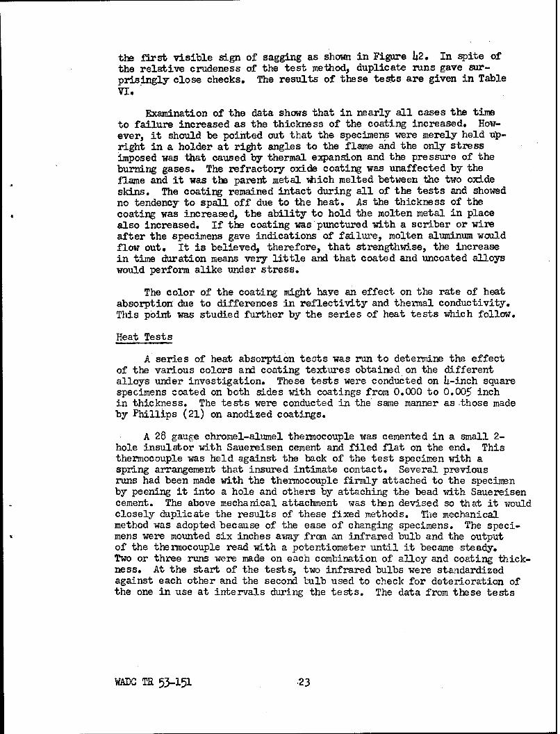
the first visible sign of sagging as shown in Figure 42. In spite ofthe relative crudeness of the test method, duplicate runs gave sur-prisingly close checks. The results of these tests are given in TableVI.
Examination of the data shows that in nearly all cases the timeto failure increased as the thickness of the coating increased. How-ever, it should be pointed out that the specimens were merely held up-right in a holder at right angles to the flame and the only stressimposed was that caused by thermal expansion and the pressure of theburning gases. The refractory oxide coating was unaffected by theflame and it was the parent metal -which melted between the two oxideskins. The coating remained intact during all of the tests and showedno tendency to spall off due to the heat. As the thickness of thecoating was increased, the ability to hold the molten metal in placealso increased. If the coating was'punctured with a scriber or wireafter the specimens gave indications of failure, molten aluminum wouldflow out. It is believed, therefore, that strengthwise, the increasein time duration means very little and that coated and uncoated alloyswould perform alike under stress.
The color of the coating might have an effect on the rate of heatabsorption due to differences in reflectivity and thermal conductivity.This point was studied further by the series of heat tests which follow.
Heat Tests
A series of heat absorption tests was run to determine the effectof the various colors and coating textures obtained on the differentalloys under investigation. These tests were conducted on 4-inch squarespecimens coated on both sides with coatings from 0.000 to 0.005 inchin thickness. The tests were conducted in the same manner as -those madeby Phillips (21) on anodized coatings.
A 28 gauge chromel-alumel thermocouple was cemented in a small 2-hole insulator with Sauereisen cement and filed flat on the end. Thisthermocouple was held against the back of the test specimen with aspring arrangement that insured intimate contact. Several previousruns had been made with the thermocouple firmly attached to the specimenby peening it into a hole and others by attaching the bead with Sauereisencement. The above mechanical attachment was then devised so that it wouldclosely duplicate the results of these fixed methods. The mechanicalmethod was adopted because of the ease of changing specimens. The speci-mens were mounted six inches away frcm an infrared bulb and the outputof the thermocouple read with a potentiometer until it became steady.Two or three runs were made on each combination of alloy and coating thick-ness. At the start of the tests, two infrared bulbs were standardizedagainst each other and the second bulb used to check for deterioration ofthe one in use at intervals during the tests. The data from these tests
WAX, TR 53-151 .23

are presented graphically in Figures 43 and 44.
The coated specimens attained a higher temperature than the un-coated ones in all cases. It was thought that the rate of temperaturerise would be appreciably different for the alloys which showed con-siderable differences in color, such as 61S which becomes jet blackupon coating as opposed to the 75S and XA78S alloys which are a lightgray in the heavier coating thicknesses. This did not prove to be thecase. It was therefore felt that, since the rates of temperature risemere approximately equal for equal thickness of sheet, the higher peaktemperatures could be explained on the basis of the insulating value ofthe coating.
Thermal Conductivity
In order to check the relative thermal conductivities of the coatedspecimens, another series of tests was made in which the 4-inch squarespecimens were coated on one side only. These specimens were testedusing the same procedure outlined above for the heat tests. The dataare plotted in Figures 45 and 46. It can be seen that the curves forthe coated specimens fall below those for the uncoated specimens in allcases when the insulating effect of the coating on the back side ofthe specimen is lost. Differences in the reflectivity of the surfaces,especially the 24S Alclad and volume of metal (XA78S was O.064-inchthick, whereas the other alloys were O.O51-inch thick) would account forvariations in the spread between the curves for the coated and uncoatedspecimens of the individual alloys. Although the above data are allqualitative in nature and the determination of physical constants hasnot been attempted, it can be inferred that the coating has a lowerthermal conductivity than the base metal for all of the alloys tested.This would no doubt be true for any aluminum alloy. The wide colorvariation which exists between the coatings on the different alloysand even in different thicknesses of coating on the same alloy seemsto have a relatively minor effect.
Effect of Coating on Tensile Strength
Tensile test specimens were machined from the wrought alloy sheetsto give a 2-1/2 inch reduced section approximately 0.500 inch wide.The casting alloys were cast into a tilting slab mold which gave a 1/2-inch thick plate. This plate was cut up into bars 1-inch wide whichwere sawed down the center edgewise to give two pieces 1/I4 inch by 1inch by 8 inches. The pieces were then heat treated. After heat treat-ing, the pieces were milled on the mold side sufficient to clean up thesurface oxidation and then the other side was milled to give a specimen0.150-inch thick. It was thought that in this manner the soundest metaladjacent to the mold face would be utilized for the test bars and theless sound center section milled away. The specimens were X-rayed beforecoating and the soundest pieces selected for test. Even with these
WADC TR 53-151 24

precautions the cast specimens showed evidence of microporosity intowhich the coating penetrated. The 220 alloy was not melted in strictaccordance with the procedure recommended by the Aluminum Company ofAmerica and the properties of the uncoated specimens did not approachthe excellent properties attainable with this alloy under ideal con-ditions.
The tensile tests were conducted on a 50,000 pound capacity BaldwinSouthwark machine. It was found necessary to chemically strip the coat-ing off of the grip ends in order to prevent them slipping. Stress-strain curves were plotted with an autographic extensometer system andthe 0.2% offset yield strength dete:ined from these curves. The dataare given in Tables VII through XV.
It has been shown in a previous section of this report, that thecoating grows an amount equal to one-half its thickness. Stated inother words, a thickness of parent metal equal to one-half the coating
.thickness is consumed in the formation of the coating. If the coatinghas a strength which is half that of the parent metal, a calculationof yield strength on the basis of original area (which includes halfthe coating thickness) should give approximately the same strength forall coating thicknesses. As the tables show, the yield strengths cal-culated on this basis show a continual decrease with increase in coatingthickness. This decrease in yield strength is greater for the higherstrength alloys and the coating strength is therefore closer to beinga fixed value rather than proportional to alloy strength. This is tobe expected inasmuch as the primary constituent of all the coatings isthe same.
The load capable of being supported by the parent metal remainingafter coating was calculated using the average of the yield strengthsof the two uncoated specimens as a basis. The load carried by thecoating was then estimated by subtracting this value from the actualload supported by the specimen. The load carried by the coating showsa general increase with coating thickness in all cases. Dividing thisvalue by the coating thickness gave a value for the load carried per0.001 inch of coating. This value shows a general decrease with in-crease in coating thickness which agrees with the observation that thethicker coatings become more powdery and porous due to the solventaction of the electrolyte. The coating appears to have an average yieldstrength value of 10,000 - 15,000 p.s.i. The calculation of tensilestrength values was not attempted because of the flaking off of thecoating in a number of cases soon after the yield strength was passedand the apparent increase in the surface crazing.
The recommended procedure for design calculation of strengthwould be to use the area of the parent metal remaining after coatingwhich is easily arrived at by subtracting half the coating thickness.for each thickness of coating applied to a given dimension.
WADC TR53-151 25

Compression Tests
The compression tests were conducted on specimens which were0.500 inch wide by 2-5/8 inches long. The thickness was that of thesheet stock which ranged from 0.032 to 0.081 inch. The cast specimenswere machined to 0.150 inch as described for the tensile tests. Thespecimens were mounted in a Montgomer-j-Templin compression jig andplaced in the Baldwin-Southwark testing machine. The platens of themachine were made parallel by rigidly clamping a spherical mountedupper platen in place after it was run down onto a 2-1/2 inch blockwith parallel sides resting on the lotier platen. Deformation wasmeasured on a dial gage mounted next to the Montgomery-Templin fixture.The results of the tests are tabulated in Tables XVI through XXIII.
The yield strength calculated on the basis of the composite showsa general increase in all cases. This is in contrast to the tensiledata where the yield strength calculated on the basis of original area(which only takes into account one-half of the coating thickness) showsa general decrease. This proves that the coating has a higher compres-sion strength than tensile strength. If the yield loads are reduceddown to load carried per 0.001 inch, the values are higher than thetensile values. The average compression yield strength of the coatingappears to lie in the range of 50,000 - 60,000 p.s.i. as compared to10,000 - 15,000 p.s.i. tensile yield strength. It is to be understoodthat these values apply only to the coating as bonded to the base metal.
In the case of coatings on compression members it is safe designpractice to use the total area of the composite (coating and metal)and the yield strength of the metal.
Rain Erosion
The resistance of the coatings on the various wrought alloys toerosion by rain when traveling at high velocity was tested in theCornell Aeronautical Laboratory, Inc. Rain Erosion Tester. In thistest the specimens are formed into a contour which simulates the lead-ing edge of an airfoil and are attached to a propeller which is rotatedat a speed that causes the midpoint of the specimens to strike a uniformrainfall at 500 m.p.h. Two thicknesses of coating were tested on eachwrought alloy. AUl of the specimens were first given a five minute runin the machine. The appearance of the specimens after this five minuterun is shown in Figure 47.
The 24S bare coatings have spalled off badly and the layers re-ferred to previously can be seen in the 0.003-inch coated specimen.The 0.005-inch coated specimens of 75S and XA78S have chipped outabout an equal amount which was taken as the end point in the nextseries of tests. The heavier coatings are evidently more susceptibleto damage than the thinner ones.
WADC 53-151 26
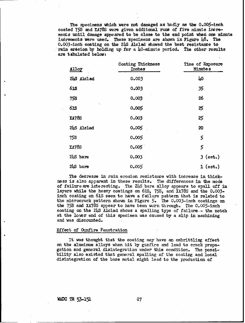
The specimens which were not damaged as badly as the 0.005-inchcoated 75S and XA78S were given additonal runs of five minute incre-merts until damage appeared to be close to the end point when one minuteincrements were used. These specimens are shown in Figure 48. The0.003-inch coating on the 24S Alclad showed the best resistance torain erasion by holding up' for a 40-minute period. The other resultsare tabulated below:
Coating Thickness Time of Exposure
Inches Minute s
24S Alclad 0.003 40
63s 0.003 35
75S 0.003 26
61s 0.005 25
XA78S 0.003 25
24S Alclad 0.005 20
75S 0.005 5
XA78S 0.005 5
24S bare 0.003 3 (est.)
24S bare 0.005 1 (este)
The decrease in rain erosion resistance with increase in thick-ness is also apparent in these results. The differences in the modeof failure are interesting. The 24S bare alloy appears to spall off inlayers while the heavy coatings on 61S, 75S, and XA78S and the 0.003-inch coating on 61S seem to have a failure pattern that is related tothe microcrack pattern shown in Figure 5. The 0.003-inch coatings onthe 75S and XA78S appear to have been worn through. The 0.005-inchcoating on the 24S Alclad shows a spanling type of failure.- the notchat the lower end of this specimen was caused by a slip in machiningand was discounted.
Effect of Gunfire Penetration
It was thought that the coating may have an embrittling effecton the aluminum alloys when hit by gunfire and lead to crack propa-gation and general disintegration under this condition. The possi-bility also existed that general spalling of the coating and localdisintegration of the base metal might lead to the production of
WADO TR 53-151 27

secondary projectiles which -wuld be undesirable.
Panels of the 24S-T4 and 75S-T6 alloys 0.081-inch thick andmeasuring 8 inches by 8 inches were coated on one side only with a0.003-inch thick coating. Uncoated panels of each alloy were usedfor comparison. The panels were mounted in a rack and fired at witha .30 caliber rifle using standard M-2 ball anmmition which producesan approximate muzzle velocity of 2800 ft./sec, The distance betweenthe muzzle and panels was 70 yards. The pane2s were mounted at twodifferent angles of incidence to the line of fire, 45 and 90 degrees.Two panels were fired for each angle of incidence; one with the coatingtoward the muzzle and one with the coating on the far side. Photo-graphs were taken of each plate fired and these are shown in Figure49. They show that there is no sign of embrittlement or crack propa-gation due to the coating process. The coating itself does not becomedetached over wide areas but spalls off only locally around the pen-etration area. It is felt that the coating would have a negligibleeffect on the ballistic limit of the alloys.
Coefficient of Expansion
The effect of 0.002-inch and 0.04-inch coatings on the coefficientof expansion was determined for all seven of the aluminum alloys underinvestigation. Dilatometer curves were also determined on uncoatedspecimens to obtain comparative data.
All specimens were approximately 5-5 inches by 316 inch by 0.081inch. A temperature range of*-400F to 600°F was covered in two stages.The higher temperature measurements were obtained by placing the speci-mens between quartz rods in a Vitreosil tube which was heated by aresistance wound tube furnace. The temperature range between -40°F and78OF was covered by placing the specimen assembly in a steel tube im-mersed in alcohol which was cooled by the freon coils of a refrigerationunit. Temperatures were measured with a thermocouple attached to thespecimen and a potentiometer.
Curves of d L/L metal vs. temperature (OF) were plotted from thevalues obtained and temperature coefficients determined from thesecurves for the temperature ranges under consideration. A deviationfrom linearity in the plots of 4 Lt* metal vs. temperature was observedwhen approaching room temperature from both directions. This deviationwas the result of "slack" in the system since the data were obtainedin both cases starting from room temperature. The coefficients ofexpansion for the ranges on either side of room temperature were obtainedby extrapolating the linear portions of the curves. Since similar anal-ysis was applied to all samples any error would be eliminated when thevalues of the coefficients were compared on a relative basis.
WADC TR 53-151 -28
The coefficients of linear expansion for the alloys investigated
are tabulated in Table XXIV.
Thermal Shock
Specimens of the five wrought alloys with 0.002-inch and 0.004-inch coating thicknesses were subjected to thermal shock by heatingthem to 930OF and quenching them in cold water. The heating andquenching were repeated five times. The condition of the coating wasdetermined by visual examination after each quench. The abrasionresistance of the coatings was measured on the Abrasiometer beforethe tests started, after the first quench and after'the fifth quench.The results of these tests are given in Table XXV.
The data show that the coating will not spall off if it should befound necessary to heat treat an aluminum alloy after it has been hardcoated; however, the data also show that there is a considerable decreasein the abrasion resistance upon heating the coating. This decrease isrelatively greater for the 0.O04-inch coating than for the 0.002-inchcoatings.
Corrosion Resistance
Test specimens were exposed to three sets of conditions which areliable to lead to metallic corrosion. The two sets of abrasion speci-mens, one of which was exposed to atmospheric conditions on an outdoorexposure rack on the roof of Cornell Aeronautical Laboratory, Inc. andthe other to high relative humidity at 80-900F, were also good checkson the relative corrodibility of the specimens in these mediums. Athird set of specimens was exposed in a salt spray cabinet accordingto A.S.T.M. Designation B117-49T. The data reported herein were ac-cumulated over a seven-month period. These tests will be continuedfor an elapsed time of one year and a supplementary report issued atthat time. At the end of a 220-day period, the coatings have stood upwell when compared with the usual anodized coatings. The failures thathave been noted to date are listed in the following paragraphs:
1. Atmospheric Exposure Test Data
At the end of a seven-month exposure to the atmosphere theonly failures that occurred were in the 24S bare allay. Thesefailures took place in the following order:
0,002-inch coating - 180 days
0.003-inch coating - 220 days
0.O04-inch coating - 180 days
0.005-inch coating - 220 days
WADC TR53-151 29

2. Humidity Test Data
The coatings on three of the seven alloys have shown somedeterioration under these conditions.
The 24S alloy coating failures occurred as follows:
0.005-inch coating - 60 days
0.OO4-inch coating - 150 days*
0.003-inch coating - 150 days
0.002-inch coating - 180 days
0.001-inch coating - 180 days
0.0005-inch coating - 150 days
The 24S Alclad coatings showed the following results:
0.005-inch coating - 30 days
O.004-ineh coating - 30 days
At the end of 220 days, these two thicknesses are theonly ones pitted.
The XA78S coatings held up as follows:
0.0005-inch coating - 120 days
0.001-inch coating - 180 days
The 220 and 356 cast alloys showed pits at the edges at theend of 90 days and show no surface pitting at the end of a 220-day period.
*All of the coatings between 0.005 inch and 0.004 inch showed some
evidence of pitting at the end of 120 days but were not considered asfailed until the times noted.
WADC TR53.-151 30

3. Salt Spray Test Data
The salt spray test data are summarized in Table XMVI. The24S bare alloy coating is the only one showing any serious de-terioration in this environment*
The corrosion test data serve to emphasize two trends which areapparent in other sections of this report.
1. The 24S bare alloy is not compatible with the hard coatingprocess used (MHC Process).
2. The heavier coatings, over 0.003-inch thickness. are not asdesirable as the coatings in the 0.002 - 0.003-inch range.
The coating itself is inert to the base metal and is not likelyto lead to galvanic corrosion as in the case of electroplatings of amore cathodic metal. There is a possibility of some difference inbehavior due to the difference in the type and concentration of uncon-verted inclusions in the coating. However, it is felt that the greatestdifference in the coatings regarding corrosion behavior is in the sound-ness of the coating. The 24S bare coatings are rough and blistery inappearance. This probably accounts for the early breakdown of thesecoatings. The 24S Alclad with heavier coatings was shown to form blistersin some cases. This could possibly explain the failures in the heaviercoatings in this alloy. The maze of cracks that form in the coating dneto differences in expansion coefficients undoubtedly act as capillary.channels down to the base metal in the presence of liquid corrosion mediawhich are even more accessible than the pores in the oxide coating itself.
Regardless of these factors, the coating adds to the corrosionresistance of aluminum alloys under conditions usually encountered inaircraft service.
DISCUSSION
A discussion of the results has been included in the individualsections covering the various tests. The data have been analyzed froma comparative standpoint regarding differences existing between thevarious alloys tested and various thicknesses of coating. Without aspecific application in mind a detailed analysis of the test data inwhich the interrelationship of the various results would be consideredis not possible. This must be left to the engineer or designer who hasa well defined application and knows the results expected.
WADC TR 53-151 31
In general, the hard oxide coating process is undoubtedly thesolution for many problems demanding a light or corrosion resistant(atmospheric) material with a hard, wear resistant surface not sub-jected to point loading. The decrease in corrosion resistance uponexposure to high humidity and atmospheric conditions could probablybe overcome by proper post-treatment of the coated surface. Theeffect of the coating on the fatigue strength raises a seriousobjection to its use in applications subject to cyclic stresses. Itis doubtful that this effect can be readily overcome. The coatingdoes not seriously affect any of the other mechanical properties.However, the minor effects on these properties may be a distinctadvantage in some applications or a disadvantage in others.
CONCLUSIONS
The direct conclusions to be drawn from the results of the indi-vidual types of tests have also been brought out in the individualreport sections on a comparative basis* The full value of the datacannot be appreciated until they are analyzed with respect to a givenapplication. The following general conclusions may be drawn:
1. The hard oxide coatings provide a means of extending theuse of aluminum and its alloys into fields hitherto restrictedto them because of their soft surface.
2. The increase in wear resistance is the most outstanding propertyconferred on aluminum alloys by the hard coatings.
3. The decrease in endurance strength brought about by the hardcoatings is the greatest objection to their use in applicationswhere high cyclic stresses are likely to be encountered.
4. The other properties of the coatings such as, dielectric strength,color, corrosion resistance, etc. may determine their choice forspecific applications.
5. A careful analysis of all of the properties of the coating andthe effect of the coating on the properties of the base metalshould be made before it is selected for other than experimentalapplications.
6. The hard coating process will undoubtedly lead to the develop-ment of new products which will be dependent upon the uniquecombinations of properties available only through its use.
WADC R53-151 32

BIBLIOGRAPHY
1. British Patent 223,994, November 3, 1924, G. D. Bengough andJohn M. Stuart.
2. U. S. Patent 1,771,910, July 29, 1930, D. Bengough and J. Stuart(England).
3. Hogaboon, George B., "Anodizing Aluminum - A Patent History andDigest", Metal Finishing, Vol. 43, No. 12, December, 1945, pp.500-503.
4. U. S. Patent Application Serial No. 157640, Martin Hard Coat(YdiC) Process.
5. "New Coated Aluminum is Wear Resistant", Aviation Week, Vol. 52,No. 26, June 26, 1950, p. 26.
6. "MHC" Light Metal Age, August, 1950, pp. 18,-20.
7. "New Hard Coating Gains Wear Applications for Aluminum", Materialsand Methods, Vol. 32, August, 1950, pp. 62-64.
8. "New Finish Gives Aluminum Good Wear Resistance", Iron Age, Vol.166, No. 8, August 24, 1950, pp. 73-75.
9. "New Hard Finish for Aluminum Alloys", Metal Finishing, November,1950, pp. 51-63, 74.
10. "Hard Surfacing Light Alloy by Anodizing", Light Metals, February,1952, pp. 46-48.
U-. "A Study of the Rain Erosion of Plastic Materials", Monthly ProgressReport for December, 1951, Cornell Aeronautical Laboratory, Inc. forWright Air Development Center, Wright-Patterson Air Force Base,Contract No. AF 33(038)-514.
12. Keller, F., "Anodic Coatings Seen Through the Microscope", Pro-ceedings A.S.T.M., Vol. 40., pp. 948-958.
13. Edwards, Junius D., "Thickness of Anodic Coatings on Aluminum",Proceedings A.S.T.M., Vol. 40, 1940, pp. 959-966.
14. Anderson, Scott, "Mechanism of Electrolytic Oxidation of Aluminum",Journal of Applied Physics, Vol. 15, June 1M9., pp. 477-480.
15. Edwards, J. and Keller, F., "The Structure of Anodic Oxide Coatings",Transactions A.I.M.E., Institute of Metals Division, Vol. 156, 1944..pp. 288-300.
WA TR 53-151 ,33

16. Frary, Francis C., "The Complexities of Aluminum Oxide", LightMetal Age, February, 1946, pp. 33-42.
17. Keller, F. and Edwards, J., "Composition and Properties of theNatural Oxide Films on Aluminum", Metal Progress, Vol. 544, 1948,pp. 195-2oo.
18. Arlt, H.G., "The Abrasion Resistance of AnodicalJy OxidizedCoatings on Aluminum", Proceedings A.S.T.M., Vol. 40, 1940, pp.967-977.
19. "Standard Method of Test for Dielectric Strength of AnodicallyCoated Aluminum", A.S.T.M. Standards, Part I-B, 1946, pp. 185-186.
20. Compton, K.G. and Mendizza, A., "Electrical Breakdown of AnodicallyOxidized Coatings on Aluminum: A Means of Checking 'knodized Fin-ishes", Proceedings A.S.T.M., Vol. 40, 1940, pp. 978-987.
21. Phillips, S.H., "Heat Testing of Aluminum Coatings", Light MetalAge, May, 1947, p. 26.
A TL 53-151 34

ACKNOWLEDGMENT
The assistance of Associate Professor M. Barton of the MetallurgyDepartment of Cornell University in the X-ray diffraction studies ofthe coating and of Mr. J. McCarthy of the Department of MetallurgicalEngineering of Rensselaer Polytechnic Institute in the determinationof the dilatometer curves, is hereby acknowledged.
We also wish to express our appreciation to Mr. R. Vanden Bergof the Aluminum Compary of America's Process Development Laboratory,and Mr. C. F. Burrows of Metal Finishers, Inc. for their cooperationand assistance in setting up the hard coating process.
WAX TR 53-151 35

TABLE I
BEND TESTS
61S-T6 o.oYl-INCH THICK
Radius Required for 900 Bend of Base Metal 1/6 - 1,6 Inch
CoatingThickness Compression Side Tension SideInchps Bend Radius - Inches Bend Radius - Inches
0-0005 74A6 flakng 14L6 base metal failure0.0005 3/6 1 "6
0.001 746 flaking 3/32 base metal failure0.001 IA i " 3A2 " "
0.002 31i flaking, 1 inch spaling* 346 base metal failure0.002 3 A 1 A inch . 3A6 .
0.003 1/2 spalling 1/8 base metal failure0.003 1/2 " **'1/2 edge flaking 1/8 B.M.
0.0o0 51/8 s•alling 3/2 bas metal failure0.00o4 1/2 1 3/32 " 0
0.005 5 spalling 3/32 base metal failureo.oo0 5 .. 3/32 " "
Note: *The term Oflaking" is used to indicate a localized pitting ofthe outer layers of the coating of approximately 1/16 inchdiameter near the center of the bent section.
**The term "spalling" is used to indicate a sudden disengagementof the full thickness of the coating, usually over an area over146 inch diameter.
***Edge spalling and edge flaking on the tension side always pre-cede failure of the base metal at about twice the bend radiusat failure. The center of the bent section is visibly sounduntil base metal failure occurs.
WDC TR 53-151 36

TABLE II
BEND TESTS
xA78S-T6 o.o64 INCH THICK
Radius Required for 900 Bend of Base Metal 3,46 - 546 Inch
CoatingThickness Compression Side. Tension SideInches Bend Radius - Inches Bend Radius - Inches
0.0005 5A6 spalling 1/4 base metal failure0.0005 1 1•,14 , . .
0.001 546 spalling 1/24 base metal failure0.001 5A46 . 54A6 ,, ,, it
0.002 7/8 base metal failure 7/8 base metal failure0.002 5A46 spalling .A it
0.003 i spalling i* base metal failure0.003 7/A6 " 3/8 " It
0.004 518 spalling 3/4 spalling at edges0.004, 7 A6 spalling 3/2 A " " "
0.005 5A spalling 5/8 spalling at edges0.005 1/A 518 " "
W= TR 5-3-151 37
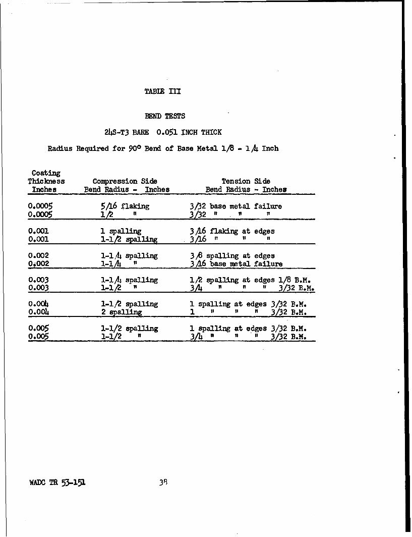
TABLE III
HEND TESTS
24S-T3 BARE O.051 INCH THICK
Radius Required for 900 Bend of Base Metal 1/B - 1/ Inch
CoatingThickness Compression Side Tension SideInches Bend Radius - Inches Bend Radius - Inches
0.0005 5A6 flaking 3/2 base metal failure0.000" 5 112 I 3/32" • ... W
0.001 1 spalling 3/6 flaking at edges0.001 1-112 spalling 346 A ,, ,
0.002 1-l,/ spalling 3 A spalling at edges0.002 1-l ." ... .. 3/16 base metal failure
0.003 1-1/4 spalling 11 spalling at edges 1/8 B.M.0.003 1-18 1 3 A I I t 3/32 B.M.
O.OO 1-1/2 spalling 1 spalling at edges 3/32 B.M.0.004 2 spalling 1 " " " 3/32 B.M.
0.005 1-1/2 spalling 1 spalling at edges 3/32 B.M.0.00_ 1-112 5332 B.3.
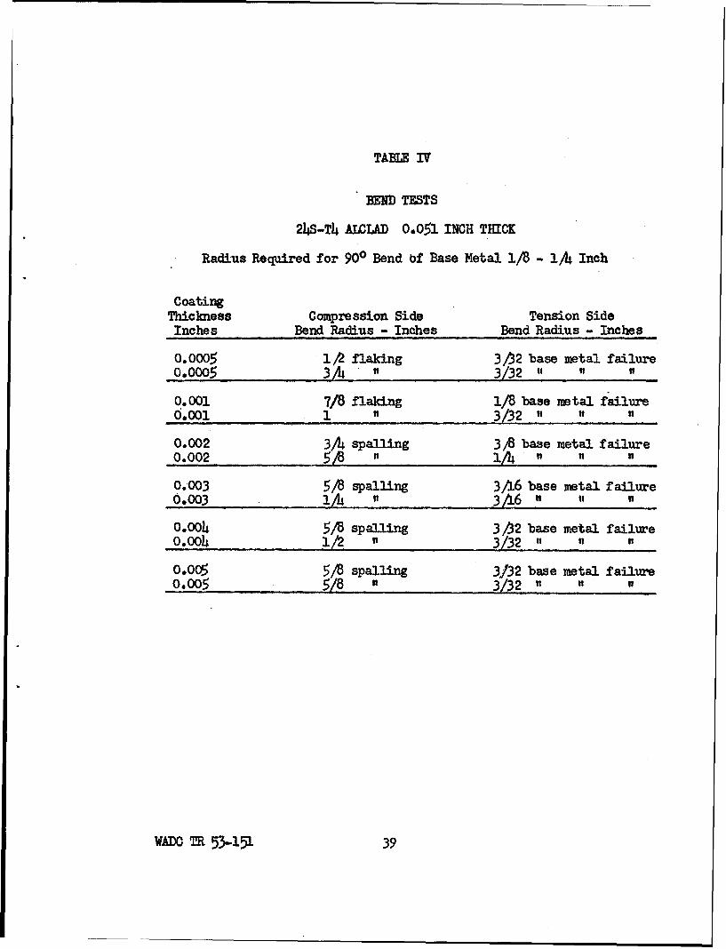
TABLE IV
BEND TESTS
24S-T4 ALOLAD 0-051 INCH THICK
Radius Required for 900 Bend bf Base Metal 1/8 - 1/4 Inch
CoatingThickness Compression Side Tension SideInches Bend Radius - Inches Bend Radius - Inches
0.0005 1,2 flaking 3/ý2 base metal failure0.0005 3/A " 3/32 ,, ,, ,
0.00i 7/8 flaking 1/8 base metal failure6.o001 1 ... _3/32 ,
0.002 3/24 spalling 3 ,8 base metal failure0.002 5/A " / 1/"4"
0.003 5/8 spalling 3A6 base metal failure0.003 lA " 3/16 "
0.004 5/8 spalling 3/52 base metal failure0.004 1/2 " 3/32 " ti
0,005 5/8 spalling 3/32 base metal failure0.005 5/8 " 3/32 "
WADC TR 53-151 39

TABIE V
BEND TESTS
75S-T6 0.051 INCH THICK
Radius Required for 900 Bend of Base Metal 3A6 - 5/16 Inch
CoatingThickness Compression Side Tension SideInches Bend Radius - Inches Bend Radius - Inches
0.0005 i/I spalling 3A6 base metal failure0.0005 3/16 - 1/8 " " "
0.001 1/4 spalling 346 base metal failure0.001 3/8 " 3A6 " "
0.002 3/8 spalling 3/16 base metal failure0.002 3,8 A 3 6 " ,
0.003 3X4 spalling 1/2 spalled edges 3/16 B.M.0.003 1/42 .12 1A B.Me.
0.004 7A6 spalling 746 spalled edges 346 B.M.0.oo0 1/2 . 1/2 5A6 B.M.
0.005 1/2 spafing 5416 " 1 A/ B.M.0.005 3/ 4 3,8 " " 1AB.M.
W TR 53-151 -4o.

U% U\ C N -- I
* ~ 0 0 0%
0
-t o
0 r4 - 0o \0 Ho 00%H 0 0ý t- 0 H 0 -40 ~04
o ~(D
?f8 4S C
00
hO 02 C) C
0
00
C.-
* 0\ %D UO U\ -- *
022
.rt4
U3 0 C/ 0 0
ol~
0)0 08 08i 0i C; ' 0 C8 00
0AD T0 5315 41 5 00

0* * O
0 N~ UN
04p. oN N
C -j en (n cli C'K C.
cd 4 3 I . 0
0 C) U- - m C
CI0 Qj
Hz~gt CHHHgigcc~i ONN. 0D "o" 0%0N 0
E-,4
e. co a: i 86 80 8
§ 8~g 8 8888co 't 'oC
9119 *% H1 01%
to A A -m--r_q2 NT_.:m I en (n -zl e
_4j'i
C) 4'cj000 I0 r-gc
M000000
41. 0rj ~~~4 .2 .L-o N\
0 9: *riA$ %0\00\%0x14"o I
0 0co 0 0 0 00 00
0 4-WAto 0R5-5 ~

bti C;
4z UMCOO =§33:18*09p 4 0O~%% 8~c 0 8C 0%
0000
E- 0 - 0 0', CO L- \0O41 4q H ri0 00
LrNCO N~
0
0
0 r *0 %C \O
H tHp
V1 P 0 UN* HHHIAHH0 mH lr
0ý E - \ 1\0 (D CO00C 83383\3CO\3a-8830
P: SO C,2C Mo ' -
0 0800 80Q0 0000H *0 0. 0 0 00\s0U)0 El-m' \lj~ NU)l N_ .
4N 43 0 0ý
000 ' 0 mcO r .Ot- CO L- CO Lr-c 0 E-- 0
0 1-4 tw NAC , At
Sc 000000000000
43) iI CM 00 00000000
4pQt 00000000000000
00I4 0 800800855 5 0 5* 00
0 00000000000001
INADC TR 53-151 143

A A co 110 S*UM IIHI A
P: 0 9000t-A JCC
m0 0
pC m
0~0 00
09 0
0 40
Is 0s R I 8
c!rl - 02 a. R.. * ** * . A
1~ 100'rCcd0.3 ~ ~ o%
0 43 OOO O; oc
02~~ C\ H~C!
Cd " 00 \0 * --rd--,---. .-
C!)ý- 4- ~ 8 888 8 88 0 0 0 00
0 0 5 P
0 V I I 0 o0 0000 0000000
V~~¶ADC NR5315

F3H r-I '0 - q
oo88888o
riH 800888§8000g,'
.. 'o op,%OZ,,,o
00
UNU
co 0t 0w0mwo
0
o ~co o
U) 100
*O 0 % C- M~ .C -
Cl)
0 ~8
W . 0 00800'U00 0-.~E-4 0 0
r-i C9C) -El I*bd 0 0 r
1194- 1 0CCCJ~~ ' UN 0 0%CCO.
0 -4a C) 00 0 0000000o C) 00 CC oIL-t l )0~
PL H - r4rH - HHHHH H HHHi -I H AýUcd bf;4. C3 0 0oo o o o o o ILA
4- 0 .ý * . * * * .9 *8 c0~~ 00 ) 00000000000k
0~ iQ i r 80 H8H H\ H\ H- r- H H t
000to C * *
WADC cu 50114

tol 0 ' 9 0 t-AUN%0 0-Q lV% UN .
-d - - -Z %0 - -*
t; , 000I O oc a .) 'Z)Cj O C o Dc o
P.
0 8 8888§8HoM00to ~H HH H rIH r4 -4P H . ý IG hC OU
Cd or, CO ,- r- cc) r- L- - , r- ol- r-
HH
100
*l mc 0 *F C -t IAtiq Ca r- ogl :tgrLC\
Q0 Q
t- 0 0 bo14 0
E -4 >; 0. 0 0 0 0 0 0 .. 0
8- 00 0C' C O 80 88
0o@Li-O C'J \0r-40H\HH \
S0
0
0(1 I 00 00000000
H I-HHHHHHHHHH 0
0 I
0)0
Cd H 0 8Q0 H ~ U'10 0 0 88 0 888 0 0 0 80 8* ~ ~ C .) * ****
E- 03 00000003000000
WADC TR 53-151 4

W6AI.0 0 H 0 .'U0\0
tO- 4-1 *+)-P,-I- -! S v
.0 ' 0 R0000000 -(12~C * L1\ U0 CU0@0 w2
4,0d C).g0-H L'- 0 1- 0(~t-
M -ý-4 C' \ ~CF\^oo rT,4 r4
4) -:0
0 000.
~ir .0-* 0P8IiP _ "jrI
0,a4 00 0\0 t c
;4 0 CM) 0 72
t0c CUN C%0 C- JCJ
too
0.'i- 0
\0 0 - P. 0m 3lO IH:,l~ r- H H CO 20(1) H~- I -
E-4H
E-4~c co 4)-i\ A -C4 0 0 '0- \0 .0
C3 1 1 - uIr- -H H HH H a)
le'Cod va *tq 0400 00
CQ -'C4CL4 0 \0 C- %-0 E-- '- %P r- H ------r-- H o T
0(12 4)00 0
H 4
0ý 9) 5rl F-I- \00()-- L 0 E- L--
04 0l1 000000-Pr
0% 0 c ~ 0HHC( \ GoIf\ a
A. 8o 0 888 0000000 mH
WADC R 55-51to

rIH S * * * 0 0 to0
E: CJ 00~~~
It :'9 o.
* a e ne S l0P4 0
a~~ 0 %
4-4'
A 00-i P
00
Cd Vr-
.09 0 aaa0
4- 4T
0 0
i-i 0 - 0_O 41 4'
PQ -Ii I J- ocH A '-J U2 4>
60 * 0-HS\ IOooo 1% a0 0
CJ'.C~j C C Jicl
0~~H 0 r4O0O\~ 42 0~
Co~ CTO rq' 'j10- cm0000 fn0 U2D E )
00Co t 00 coE-\
00
E E- 0 000000 *WADC4 CH 5315 5

0 0,
*a-8' I IO
co 0 AS9 l .90LA'L\ 0 000
00
0 .0 0 000 *a *0 00
.14 Ci) r
E-41
.0 VHo- 0 ,00000@00 00
U3)
24- I 000000000000
ol 01 0000000000--.t000
o0 0 0000000000000
WADC R 53-51 5
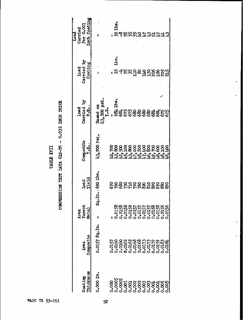
ObO
0 W4 31A ~ ~ Uo to
0d()- o-- RN0800Sý ~f
0
H 00
%00
E-~
Vr4
toGH 0%
ot
0 D Ll \C --Cd ~ ~ toV9 A\A Dt- -t E0
0 00 r,00000000000 r-
0 0000000000000
10
AE 000 0 0 0 0
WADC TR 53-151 52

U I0
41 10
-cot 0 %Id 00 UN ---t m0I Ir-ir-1H HH
(d 1)4-) 00000 000 00
0 HH~r4-ifC.i 9 4 Q 2tcJH
0 0 P
0 '0,00"!UUCýi
C~*
%0 mO
c''8
00 co A'C3 l
cd (1 0 O\ cl00 1 0
0) Fl4M 0 000
-ý an \ J0.rCIm " c .... ci I n (
00000000000*0
S(30 0 HV H - ~4>0 00000008000000Cd-l0 0000 0 0 0 0
o0 : ;C 38ooC *o ;
WADC ~C *R5-115
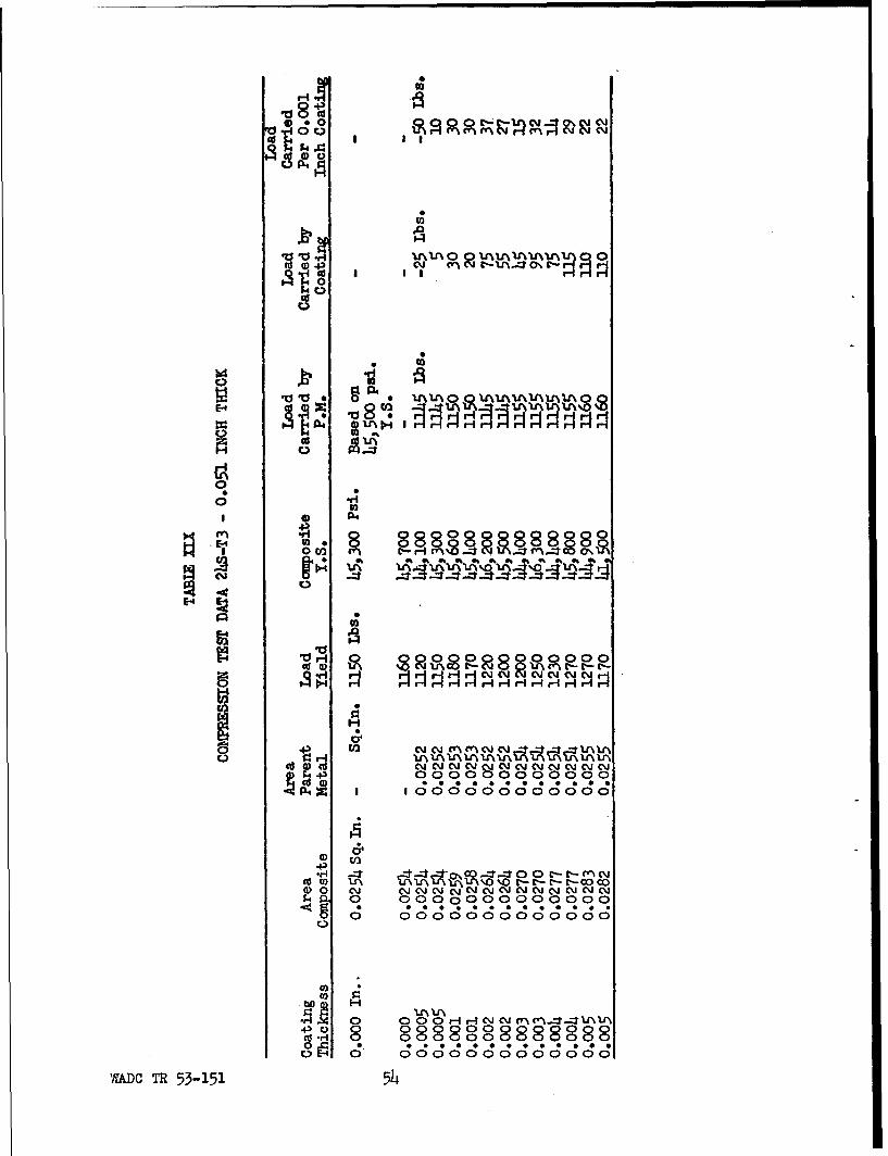
P-4
M~I
00
0.
00
en 8
0 V;C
o .1-
EAAH1 H r4rrr-I HIr- -
C; C;0
00 0 : -- 0~ JC- r MC\I(EO ccAccccocc
0 00000000880000
b0D H
0 UNV
%ADO TR 53-151 5L4

0 4~
~0 cd Cl
U .Q
CI-i
U)
00HUca0 *~ 9 Jto4
to
C~j O
0dr N EL\L ~ l qc :- ýr
0
(1)
02
'rA 0 000008800800~4 0801 (; c ( * ;C3o8c;oo *
WAC R 3-515

.00
0,
~ .d~to
0 E 0
00
ot
\0 0.8ý§8§8Lr 01 .0S%
0 000000000
0 C
9 000000000000
0 0000000000000
* 0 H~ " 0 Q m m -- 0 * %0 0 0
UE40 00000000000001
WADC R 53-51 5

04') 4-)
'dti, .1 0 0 a
p 430 P-4 r.:
00 H 0c
0
101 0 0 0 0 O\'0\C\ODcl0.d a) A1~U ~'O.
i- P- (1) ri ri H(a.4 0
H 4-)01 4-)J
0r 0080 0
IVm 00 000 00 n 0 m88 C)N P~C4 '.0cl 0 * CO E.-l0rc c,.
0- clJ . .cJ0.\OP-
E-e
00
E- '.'0..-c' C
U~ C'j C'J (
-430
0)
.02
W0 r- E0+-E-'-E-r
4'V
0
tio H1
4'c 0 00088Q00 01C 000 00o 4
*A 00 - * 0QE~ 00000001 4
WALDC MR 53-151 57

vt;00
0 0
05.4C~ S I II00
00 00000
040 0 -4 ;:CC- 4')
0 54P4"
* 4308
0~~.- 0 sci ci S 8
0~ 0, %As
00
riH 1 0 ( r a c
c 0.
00 00 C)
g4- I 000000
4 a001 Ul 043
4')
S0 Lý - -r--C- L-E- E-
0 : 0000000 d
C~~Z C C C C
a)
bD t
0 E-4 0 0000000 Z
AADC TR 53-151 5

TABLE XXIV
COEFFICIENTS OF EXPANSION
CoatingThickness
Alloy Inches (-40)-680 F 68-212°F 68-392OF 68-572OF
61S 0.00 *9.35 10.h 12.7 13.75
61s 0.002 9.5 12.6 13.4 13.6
61S O.0035 10.35 11.9 13.05 13.3
XA78S 0.00 9.86 12.9 13.9 13.75
XA78S 0.002 9.6 12.45 13.6 13.35
XA78S O.1004 9.85 12.05 13.3 13.5
24S 0.00 10.1 13.0 13.5 14.6
24S 0.002 9.6 11.6 12.8 13.75
24S 0.004 9.8 11.0 12.7 13.8
24S 0.00 9.85 12.1 13.2 14.1Alclad
24 S 0.002 9.35 12.65 13.5 14.1Alclad
24S O.004 9.55 11.85 12.4 13.4Alclad
75S 0.00 9-5 11.1 13.6 13.6
75S 0.002 9.8 13.6 14.0 i3.9
75S 0.004 10.1 12.1. 13,8 13.65
356 0.00 9.14 11.25 12.55 13.7
356 0.002 9.0 10.8 12.85 13,7
356 0.004 9.5 11.6 12.1 13.4
220 0.00 10.1 13.65 14.1 14.45
220 0.002 10.7 13.6 13.9 14.3
220 0.00,4 10.35 12.6 13.7 14.3
NMultiply all values by 10-6
WADC M 53-151 -59-

TABLE XXV
THERMAL SHOCK TESTS
XA78S - O.0O4-inch coating spalled off slightly after 4th shock.
24S - 0.004-inch coating spalled off slightly after 4th shock.
75S - 0.004-inch coating spalled off slightly after 4th shock.
ABRASION TEST DATA
After 1st After 5thAs-Coated Quench QuenchAbrasion Abrasion Abrasion
Coating Resistance Resistance ResistanceThickness Grams of Grams of Grams of
Alloy Inches Abrasive Abrasive Abrasive
61S 0.002 358 299 274
61s 0.0035 743 550 554
XA78S 0.0002 259 294 269
XA78S 0.0004 551 214* 280
24S 0.002 191 161 184
24S 0.004 231 191 74*
24s Alclad 0.002 522 336 334
2hS Alclad 0.004 1071 639 500
75S 0.002 451 322 432
75S 0.00o4 679 334* 30**Coating flaked off during abrasion test.
WADC T 53-151 -6o-

0(0
5~02 * ** *W
mI.a. 43
EO(0
40-
N ~00*U * N *%0 m H
WAD TR- 5315 6

z)LLJZZ
zzj~
La00,
000'i I ISd 'rS'22a'I
--- J
I.- tu11.N
Li'~ -J%-
a4 0 D 3ý
0000 0 000 0 0 0)
£J73A4s 'SA JOi; V
W&DC TR 53-151 62

N 0 j
N Ncw - I ,J- -4
Q)~
fl~lu
rk
Lu0
WAOTR 53-151 63

GROWTH DLRING COAr/NG
.005
1.004
00,0
.00 - -0 oz.03-0
6Awm- ~ce
Fe.
WA'TR5-116

CGOMEROIALLY PRE ALUMIIlK SalMT UITH 0.003-INCH C0ATI]I
GRAZED PATTERN DUZ TO DIFFERENTIAL THEMAL EPANSIC&.SCNE CRACKS WERE PSENT WHEN PIECE WAS RANDVED FGIITE BATH.
WAC TR 53-151 65

24S Alclad P-S Alclad0.031-inch Thick 0.082-inch Thick0.0022-inch Clad. 0.00,6-inch Clad.0.004-inch Coating 0.04-inch Coating
Blisters on 24S Alclad Sheet Which Occurred When theHard Coating Thickness Zxceeded the Thickness of theCladding.
Figure 6
WADC TH 53-1.51 66

UWOOATM SPOOL FOR HYflRAULIC CON1TROL VALUE~
MADE FRQM 24S AND LAJPPM TO HIGH FINISH
SAME! SIOQL AS ABO0VE WITH 0.003-INH 00ATEIJ APPLIM
NOTE BRtJGHUESS OF SURFACL -AN ALLOWACi OF 0.0005INCH WAS 1Pi0VIUMI FOR HONING TO A S4OOTH FINISH
Figure 7
WADC TR 53-151 6

144
c;
0o w0
88
4- ID 0)
•0• .
r4-
4-U
po
42~-
S510
w~xf C 53-..151
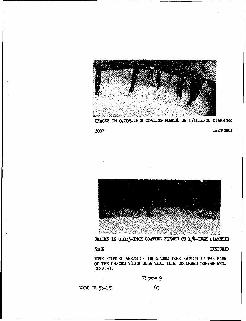
MCMAK IN 0.003-INCH COATING JOIAE ON 1/16.INCE DIJVW=E
3001 UNBTCHDM
CRACs IN 0.003-DiCE COATING FoBmHI ON 1, 4&.iJcH DiAMETE
300 METCHM
NOTE ROUNDE AROAS OF INCPSAME PEN'RTWI0N AT THig BASEOF THE CRA.CKS WHICH SHOW THAT flEET OCCURRE DMINlG PRO..CESSING.
Figmr 9
WAt)C MR 53-151 69

,- Hard Coat
(- 61s Alloy
500= Polarized Light
Structure of Coating on 61S Alloy WhenIlluminated With Polarized Light
Except for the layer of material next tothe base metal, the microstructure of thecoating on 61S Alloy is homogeneous.
Figure i0
WADC 53-151 70

(wHard Coat
S, -24S Alloy
50oX UhetchedStructure of Coating on 24S Alloy as Observed
When Illuminated by White Light
Figure 31
(-Hard Coat
(-2• s Alloy
5=O Polarized Light
Leyer Structure of Coating on J4S Alloyas Brought Out by Polarized Light
Figure 12
WADC TR 53-151 71

Umetcbsd
Structure of the Coating on 356 Casting Alloy
The free silicon in the cast structureremains undisturbed except for anexpansion perpendicular to the interface.
Figure 13
WADC TR 53-151 72

Exposure Back on the Roof of Cornell Aeronautical LaboratoryWhich is Located ia a Semi-Industrial Atmosphere
Figure 14
WAI)C MR 53-151 73

- - , - -
__ ____I _ ____ _
3-CU
(ji
U3 10 oII w ~
L~4 t/ ISI 9 ed OSY)~l-
.70NVI$S/'1S3d NIOI.WTIV (G
Q4O
QLj
131
o o_
I-o * * 0
3ONV.IP1S'3d NOI/'VcgV
W.ADC TR 53-151 714

04 0 0 Ok
QvI-
1.4 k -_
(3_ _4_ -
Cr) t. -
0 p Hs.t (0i spvey) '- so eoln
WADC tIR3 03915 75Vd~J ~QO f

Ct) m
0 6
Cr) U
OV l Mr'3V 091 £'bvey Jo go-7alNnP1
JONVIS/IS.Yd NOISV&GV
oo
Lii
0-
Cd) P) QQ
0rp ow __vey -yo __ __ __n
WADO TR 53-151 76
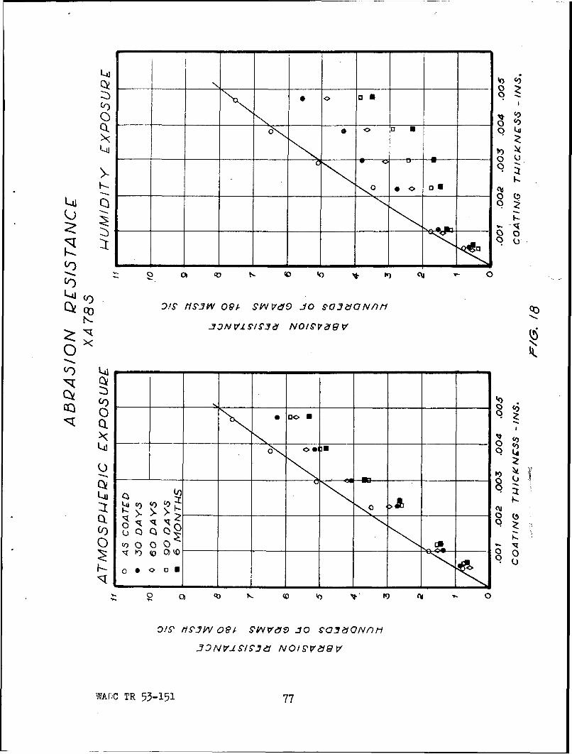
0)~
1ua 0(
L-4-
Vr) L4
Q~)
U)D~
Cd) c -
C) ONL.
os
iS 1,9-W 091 S'kV VC V10 6'O~edQNnMP
N~f1VS~1' O/gpv&G
W;CTR 53-151 77

L4
0 _4
L4
L4) O' H Pf# Y P SYV e JOS'03CdaNfl
'2 OOR 01 i
q0 '
o 0 0
ocO!S' SýJPV09 #VrO-0SJZGn
-O VL'SJ _ _ - _ _ _ - 00
WACTR5-117

LLjJ
Li4
(JQQL
Q) 00 0 - 0
0
~~C0
O~ 33WVJiS7.7 op Nge o Pc~aUV
-AC TR 5315 79 - I
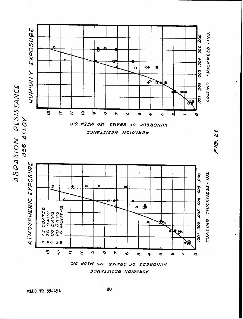
-- to
)K00
AI)
o L--i -4
NM 12
-AU
O!K1,.P 9 o Sae~t
(r)e
~3NV.LC/S'.Y NOIV.'
t%4%
(OOv
I-I-
0) C N (
u~ccP- - m - 0
0yJV0iS vr oc.aon
wA~c R 53-5- o

(~Q)
K iZ
Ci~) N
3$ V.170A IVMOcDVYV3a'g
k4J
Q I
Cl)C3
70 NM 0 G0 3 6
WADC TR 53-151

C~i
Cý 10
COa
3fDVIL70A NMOGAV3af
W KCT 3118

00
Q) ) 0
CfQ)
39V.70A NVM 0 /MV3 6,
-1D -R5311.9

DILL PCTP•C ST[AIGCT-/
220 ALLOY
4000
J 000
200
1000
0 .0Of .00. .003 .004 .005
COA TING TH/CA•NESS - IN.
FIG. 2 5
'. TR 53-151
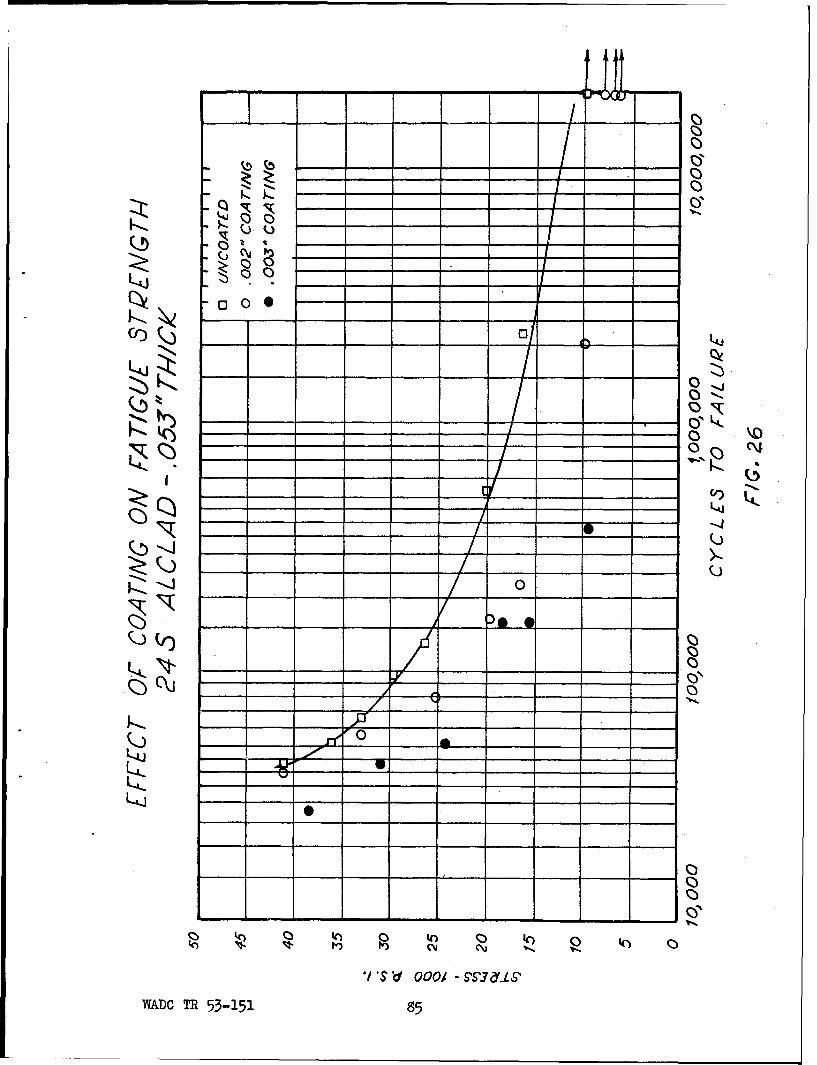
__o 0 A
00
__ S' 00W 00.-7dNWA- TR 53-151K 5

L-4 -
~,00
k)) 900k
Kc _ _ _ - -
1/ 01 f0 01 SI7fL
K AC 53-151 ___ 6~
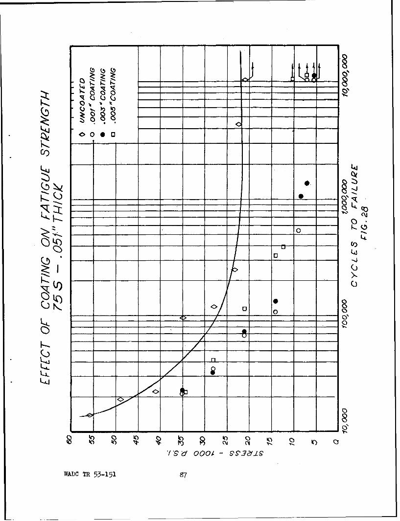
__ 0
cos
~O00
K -4
Co0
KQ
,Q)_
LA(J
0100 <<>0
_ _'V d_ _ _0 _ _ _ _ _ _ _ 0 _ _
____ ___ 53_15 _____7___0

F-4- -
40 0
L4-J-
0) 040 Nb
'S d 00/ S','-7(-L SWAD - -5315 0

0-
LAI
Qi)
LuL
K)~- 00-it
0 Cý C14 q
_ _o _ _,. _ _ -1.
WADC R 53-51 0

0
zt i
Laj
Cial
__00 -__S __ __- -
0 -
WA6DCTR 53151 g

- I - -0
01 . 0.
___z, ___ __ _ __ 0'
1413
- -014. _ _ _ _ _ _ _ , C-_ _~~ ~~~ N_ _ __ _ _4)
o 0
000
It0
0 14)_ _~C N__ _
o~S o o ____ ___ __ - ___
,?AD _ _ 53_15 0 _
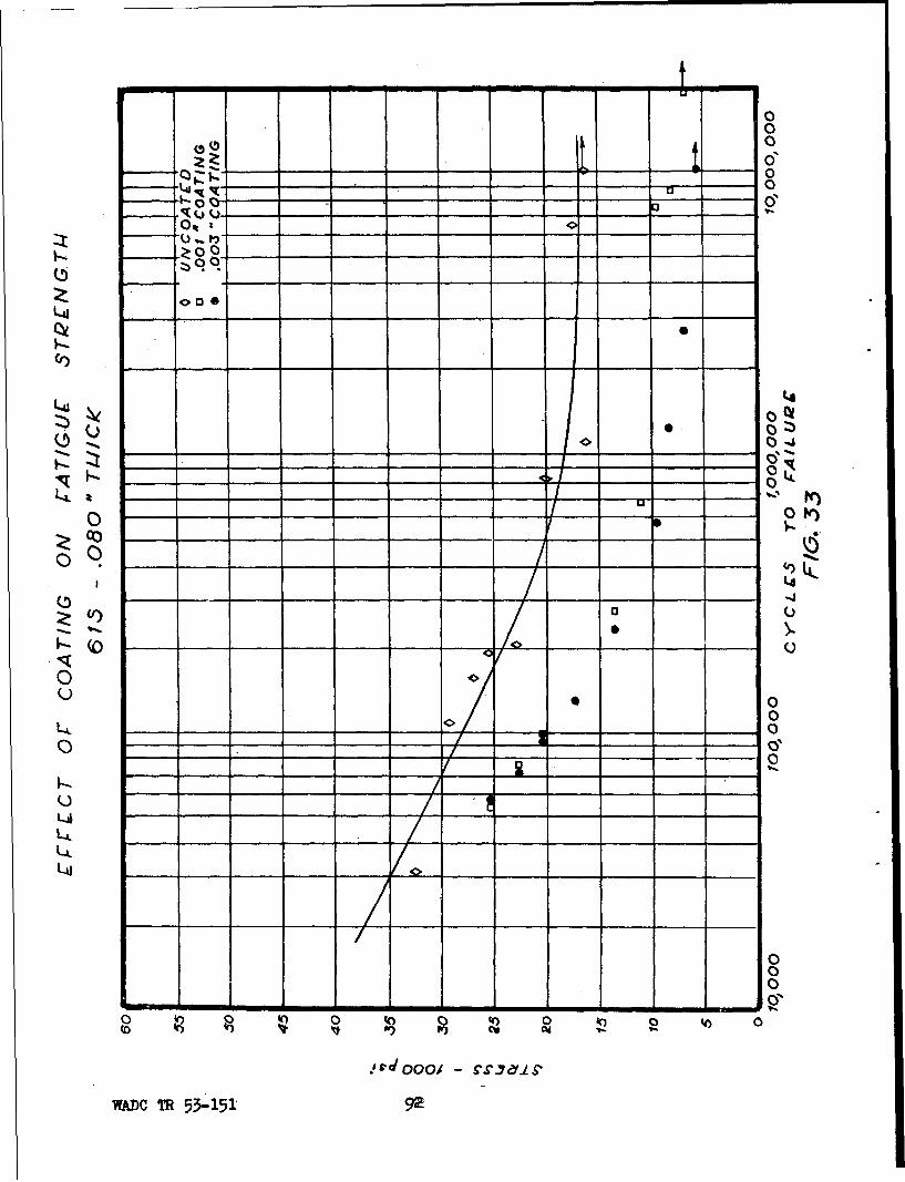
0
0 93 0
0 it
Ct)
L4g
* 0t
0
0
LA~
0 -L-A. O(
o9 - _ _
In 0-4
* 00i r -7fLS
WADC R 53-51 9

i-_0
'Iq
_ _ _ _ _ _ _ 4 k
00C _ __ _ _
00
tO 40
00'., SL~ E
WADC R 53-51 9
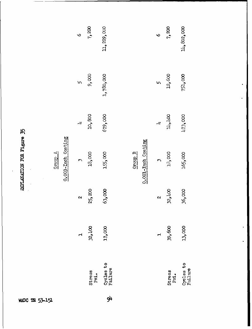
N0 0% '%10 0.r- C C- CMj
0 0
00
co 8
0% 0 0co 0 C
P4 CT-
0 Q- 0 0
00 8P: Olo CC-
1-4 H -I-I\
0H0 0
9 0
0 C0
80
R H
8 0
M HHH
0.r0
to ca U
WARc253-151 9
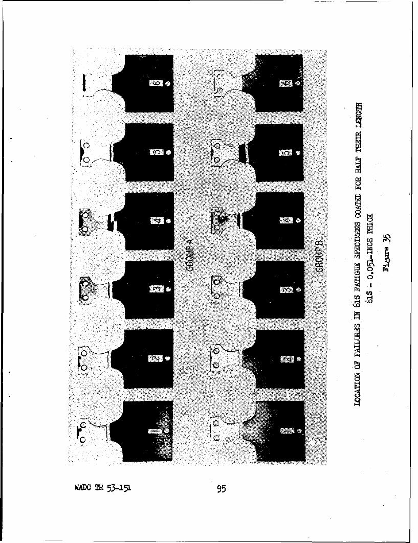
10C)4
EF2
fx~n
WAiJO TR 53-151 95

-00
Q 0i
0
L44
U))
Lt
L40
0
0,0 _ _0 0_ o _ a
o o~Cl N_ V._ _ _ _
00/ -dyyig
TIADCTR 53151 9

u 01
0'
Z00
O.D Qo
400
'-a' L4
0 -
Q( II) 0 A
0o _ _ _ _ _ _ __ _ _ _ -0
0
U~~~V ___ __ _ _ ___ _
Lii- .,- f.
WA* L. 5_15 97

- m ~ - ma
L0'
Ctz)
00
- 0
01 -
000
- -- k
0
-* ooo - -p7d.
WA.DO TR 53-151 9

Bend Test on P#S-T3 Alloy With O.O02,-Inch CoatingCoating peeled off in layers.
Bend Test on 24S-T3 Alloy With 0.001-Inch Coativg
Outer laer has peeled off for a considerable dis-tance while layer in contact with base metal haspitted only slightly.
Figure 39
WADC TR 53-151 99

Bend Test 24S-T3 Alloy With O.O04-Inch Coating
Coating spelled off in full thickness.
Bend Test on 61S Alloy With 0.004-Inch CoatingCoating spelled off over wide area when initialfailure occurred. Edg spalling precedes generalfailure.
iiure 4o
WADC M 53-151 100
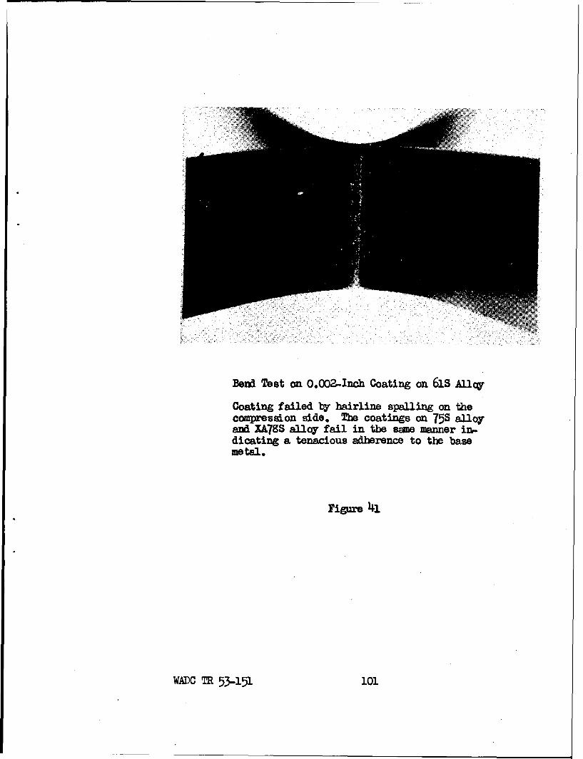
Beod Test on 0.002-Inch Coating on 61S Alloy
Coating failed by hairline spalling on thecompresdon side. The coatings on 75S alloyand XA78S alloy fail in the sme manner in..dicating a tenacious adherence to the basemetal.
Figure 41
WADC TR 53-151 101

co
H
5
0
I coJ
U) H- oI
WIADC TR 55-151 102

IDtot
4xr
WA1DC TR 53-151 103

-d z Iu 00 0 O 0 0
0 0 L
-~ R_ I _
UC
LAI-
1. ._. .__ 1
LA
(000 000 0 ~00 0.0 0-6 d --
kZ
40 140
Jo IdWo -10 dw-
WADC R5-5 o

4-b
0.0
t~~~2Ld
CCj
0 -0 __
000I-~ ~~ý 9;1--cci.4 C
O~DCu
0 (D 0_ _
'0.00
_ 6 -
- -0 a 11
0C 0 0 0
S KI .JoWAM m ~ 5311_0

00 1-00
00 0t 00__00 Z)00
Q) Wt
000
0U U
00c
F- 00C-
* 0
_ _ _ _ _. -1 o d - 0--
WAD0 TR 53e 0

0 00
00
00 '
00 C1)
Qt_ _
CU"
wADO TR 53-151 107

o n
LI%
CC
0 I
WADC TR 53-151 109

0- Ln
Ln
wm TR5,$-11 10

040
E4cu
.to
o to
IL3
WADCTR 5-1513.o

Ln
02
ta)
P~4
W=D !lR 53..151 ul

EXYPLANATION OF FIGURE 49
Panel No. 1 2 3Alloy 21tS-T4 24S-T4 24S-T4Coating Thickness - Inches 0.000 0.003 0.003Angle of Panel 450 450 450Side Shown Exit Exit Entrance
Panel No. 4 5 6Alloy 214S-T4 21aS-T4 24S-T4Coating Thickness - Inches 0.000 0.003 0.003
Angle of Panel 900 900 900Side Shown Exit Exit Entrance
Panel No. 7 8 9
Alloy 75S-T6 75S-T6 75S-T6Coating Thickness - Inches 0.000 0.003 0.003Angle of Panel 450 450 450Side Shown Exit Exit Entrance
Panel No. 10 31 12Alloy 75S-T6 75S-T6 75S-T6Coating Thickness - Inches O.0OO 0.003 0.003Angle of Panel 900 900 900
Side Shown Exit Entrance Exit
WADJC TR 53-151 112

EF"iHCT OF GWNIBIE PNFATRATPICN
Figure 49
WADO TR 53-15i. U3