study of qos management in ieee 802.11 and 802.11e mac ...ethesis.nitrkl.ac.in/2522/1/endsem.pdf ·...
TRANSCRIPT

Study of QoS Management In
IEEE 802.11 and 802.11e
MAC Layer Protocols
Sujeet Bhushan (107CS002)Nirmalya Ganguly (107CS029)B.Tech
2007-2011
GuideProf. Suchismita Chinara
Department of Computer Science and Engineering
National Institute of Technology Rourkela
Rourkela-769 008, Orissa, India

Study of QoS Management In
IEEE 802.11 and 802.11e
MAC Layer Protocol
Thesis submitted in
May 2011
to the department of
Computer Science and Engineering
of
National Institute of Technology Rourkela
in partial fulfilment of the requirements
for the degree of
Bachelor of Technology
by
Sujeet Bhushan
(Roll 107CS002)
Nirmalya Ganguly
(Roll 107CS029)
under the supervision of
Prof. Suchismita Chinara
Department of Computer Science and Engineering
National Institute of Technology Rourkela
Rourkela 769 008, India
2
This is to certify that the work in the thesis entitled Study of QoS Man-
agement in IEEE 802.11 and 802.11e MAC layer wireless protocols,,
submitted by Sujeet Bhushan and Nirmalya Ganguly , bearing roll numbers
107CS002 and 107CS029 respectively, is a record of the original research work
carried out by them under my supervision and guidance in partial fulfillment of the
requirements for the award of the degree of Bachelor of Technology in Computer
Science and Engineering during the session 2007-2011 in the Department of Com-
puter Science and Engineering, National Institute of Technology Rourkela. Neither
this thesis nor any part of it has been submitted for any degree or academic award
elsewhere.
Prof. Suchismita Chinara
Department of CSE
NIT Rourkela
Place: NIT Rourkela
Date:
3

Acknowledgement
This thesis would not have been possible without the inimitable support and guidance
of many individuals. Even though mere words cannot qualify the help that they have
given us, we shall yet attempt to thank them in this feeble manner.
The person we are most indebted to is Prof. Suchsmita Chinara, CSE De-
partment of NIT Rourkela. Her invaluable advice and spur given to us has inspired
us to broaden our horizons and accomplish tasks that we never thought were possible.
She believed in us even when we did not believe in ourselves. Our sincere thanks
to maam, for her constant encouragement and her support in our endeavor to un-
derstand our area of research. We truly appreciate and value her esteemed guidance
and encouragement from the beginning to the end of this thesis. She has been our
source of inspiration throughout the thesis work and without her invaluable advice
and assistance it would not have been possible for us to complete this thesis.
We are grateful to Prof. Ashok Kumar Turuk(HOD) for his valuable sug-
gestions, and encouragements during this research period. For all these, and more,
thank you, Chinara maam and Turuk Sir.
Prof. (Dr.) R. Baliarsingh and Prof. (Dr.) S.K. Jena, offered timely and
supportive counsel and has always been eminently approachable. Along with Prof.
(Dr.) B. Majhi supervised our tutoring at CSE department of NIT Rourkela. Our
sincere thanks goes to Prof. S. K. Rath and Prof. D.P. Mohapatra, Prof. P. M.
Khilar for motivating us to work harder. This work has helped us to grow both pro-
fessionally and personally. We would like to thank to Prof. P. K. Sa to motive and
suggest towards research work as our teacher and friend.
We would like to express my thanks to our Department at NIT Rourkela,
peer support. Indeed, given the atmosphere of congeniality we have enjoyed during
our research, we must offer a blanket thank you to all the staff with whom we have
worked at NIT Rourkela. And, finally, we must thank our family, have provided us
with the love, stability, and practicality that has allowed us to persist with studying.
Such a connection is valuable in itself.
Sujeet Bhushan and Nirmalya Ganguly
4

Abstract
Wireless networks have become increasingly popular in recent times and it
has become a pressing need to ensure that the various applications using it
get the necessary Quality of service. Wireless networks being inherently dif-
ferent from wired networks and pose a unique set of challenges . Quality of
Service(QoS) is defined as the performance offered by a network to its users
in terms of providing resource assurance and service differentiation to different
kinds of traffic flows .Due to scarcity of bandwidth and high rate of packet loss
in wireless networks providing QoS to time critical applications is a challeng-
ing task .In this thesis we attempt to study the QoS management strategies
applied by the wireless networks at the MAC layer .The most common QoS
provisioning strategy is to prioritize the different classes of traffic and make
sure that the high priority traffic gets preferential access to the channel .In this
thesis ,a study of the binary exponential back-off algorithm which is used by the
wireless MAC protocols has been done and an improvement has been proposed
in which the Contention Window(CW) is varied in a non-uniform manner for
different access categories with an aim to improve the performance parameters.
The CW defines the range[0,CW] from which a random no of slots are chosen
by a station in case of a failure in transmission for backing off before attempt-
ing to transmit again. To demonstrate the effect of the modified contention
window variation scheme simulations have been carried out using the Qualnet
Simulator designed by Scalable Network Technologies, Inc. After implementing
the proposed modification a performance comparison has been carried out for
parameters such as packet delivery ratio, throughput and jitter.
5

Table 1: List of Acronyms
Acronyms Description
AC Access Categories
ACK Acknowledgement
AIFS Arbitration Inter Frame Space
AP Access Point
BC Backoff Counter
BEB Binary Exponential Backoff
BSS Basic Service Set
CAP Controlled Access Period
CBR Constant Bit Rate
CP Contention Period
CSMA/CA Carrier Sense Multiple Access / Collision Avoidance
CTS Clear to Send
CW Contention Window
DCF Distributed Coordination Function
DIFS Distributed Inter Frame Space
EDCF Enhanced Distributed Channel Function
FIFO First In First Out
FTP File Transmission Protocol
HC Hybrid Coordinator
HCF Hybrid Coordination Function
IBSS Independent Basic Service Set
IEEE Institute of Electrical and Electronics Engineers
IFS Inter Frame Space
MAC Medium Access Controller
NAV Network Allocation Vector
PCF Point Coordination Function
PHY Physical Layer
PIFS PCF Inter Frame Space
RTS Request to Send
SD Slow Contention Window Decrease
6

Acronyms Description
SIFS Short Interframe Space
TBTT Target Beacon Transmission Time
TXOP Transmission Opportunity
QAP Quality Access Point
QBSS Quality Basic Service Set
QoS Quality of Service
WLAN Wireless Local Area Network
7
List of Tables
1 List of Acronyms . . . . . . . . . . . . . . . . . . . . . . . . . . . . 6
List of Figures
1 EDCF access Mechanism . . . . . . . . . . . . . . . . . . . . . . . . . 20
2 HCF access Mechanism . . . . . . . . . . . . . . . . . . . . . . . . . . 21
3 Screen Shot of Scenario . . . . . . . . . . . . . . . . . . . . . . . . . . 28
4 Packet Delivery Ratio VS No. of Packets sent . . . . . . . . . . . . . 29
5 Throughput VS No. of Packets sent . . . . . . . . . . . . . . . . . . . 30
6 Jitter VS No. of Packets sent . . . . . . . . . . . . . . . . . . . . . . 31
7 Packets Delivery Ratio VS No. of Packets sent . . . . . . . . . . . . . 32
8 Throughput VS No. of Packets sent . . . . . . . . . . . . . . . . . . . 33
9 Jitter VS No. of Packets sent . . . . . . . . . . . . . . . . . . . . . . 34
8

Contents
Certificate 3
1 Chapter 11
1.1 Motivation . . . . . . . . . . . . . . . . . . . . . . . . . . . . . . . . . 12
1.2 Aspects of Qos Management . . . . . . . . . . . . . . . . . . . . . . . 12
1.3 Thesis Outline . . . . . . . . . . . . . . . . . . . . . . . . . . . . . . . 13
2 Chapter 14
2.1 The 802.11 Physical Layer . . . . . . . . . . . . . . . . . . . . . . . . 14
2.2 The 802.11 MAC Sublayer . . . . . . . . . . . . . . . . . . . . . . . . 14
2.3 The 802.11 Distributed Coordination Function(DCF): . . . . . . . . . 15
2.4 The 802.11 Point Coordination Function(PCF) . . . . . . . . . . . . . 17
2.5 Inter Frame Spaces Defined In IEEE 802.11 . . . . . . . . . . . . . . 17
2.6 Services Offered by IEEE 802.11 . . . . . . . . . . . . . . . . . . . . . 18
3 Chapter 19
3.1 Enhanced distributed coordination function (EDCF): . . . . . . . . . 19
3.2 Hybrid coordination function(HCF): . . . . . . . . . . . . . . . . . . 21
4 Chapter 22
4.1 Different back-off algorithms and Contention Window management
schemes . . . . . . . . . . . . . . . . . . . . . . . . . . . . . . . . . . 22
4.2 Characteristics of the original EDCF scheme . . . . . . . . . . . . . 23
4.3 Proposed Modification . . . . . . . . . . . . . . . . . . . . . . . . . . 24
4.4 Module Description . . . . . . . . . . . . . . . . . . . . . . . . . . . . 25
4.5 Module Description . . . . . . . . . . . . . . . . . . . . . . . . . . . 26
5 Chapter 27
5.1 Simulations . . . . . . . . . . . . . . . . . . . . . . . . . . . . . . . . 27
5.2 Results . . . . . . . . . . . . . . . . . . . . . . . . . . . . . . . . . . . 28
5.2.1 For Static Nodes . . . . . . . . . . . . . . . . . . . . . . . . . 29
5.2.2 For Mobile Nodes . . . . . . . . . . . . . . . . . . . . . . . . . 32
9

6 Chapter 35
6.1 Conclusion . . . . . . . . . . . . . . . . . . . . . . . . . . . . . . . . . 35
6.2 Future Work . . . . . . . . . . . . . . . . . . . . . . . . . . . . . . . . 35
References 36
10

1 Chapter
IntroductionNodes in an ad-hoc wireless network share a common broadcast radio channel. Since
the radio spectrum is limited ,the bandwidth available for communication in such net-
work is also limited .Access to the shared medium should be controlled in a manner
that all the nodes get a fair share of the available bandwidth ,and that the bandwidth
is utilized efficiently .Since the characteristics of the wireless medium are completely
different from those of a wired medium ,and since ad-hoc wireless networks need to ad-
dress unique issues such as node mobility ,limited bandwidth availability ,error prone
broadcast channel ,hidden and exposed terminal problems and power constraints that
are not applicable to wired networks ,a different set of protocols is required for con-
trolling access to the shared medium in such networks[1] .The Wireless LAN(WLAN)
has been standardized by the IEEE 802.11 specification[3] .The popularity of wireless
LANs has grown very rapidly since its introduction mainly due to the rapid growth in
the number of wireless devices such as mobile phones ,laptops etc .This has resulted
in an increasing demand for quality of service for applications which run on these
devices. Real time applications involving voice or video transmissions over a network
have stringent requirements in terms of delay, bandwidth and other QoS parameters.
Hence, QoS must be provided by the underlying network for proper functioning of
those applications. One way to achieve this is to provide QoS at the MAC layer,
which makes physical bandwidth usable. But IEEE 802.11, which is the most preva-
lent WLAN technology, does not have any inherent QoS support . The IEEE 802.11
MAC uses DCF (Distributed Coordination Function) for media access among the
participating network nodes. But DCF alone is neither capable nor suitable for ful-
filling the QoS requirements of real time applications like voice and video. It does
not provide any priority and there is no service differentiation between different flows.
Generally, the proposed QoS schemes which are based on IEEE 802.11 try to improve
DCF functionality. There are primarily three ways in which QoS is provided by mod-
ifying DCF based MAC:
• Prioritization among different classes of traffic: Most of the techniques use different
11
Inter Frame Space(IFSs) or different Contention Window (CWs) or both [4][6][7][8][10].
• Resource allocation to prioritized classes of data: This is achieved by some dis-
tributed variant of Weighted Fair Queuing (WFQ).
• Admission control: QoS is provided by measurement and model based admission
control[5].
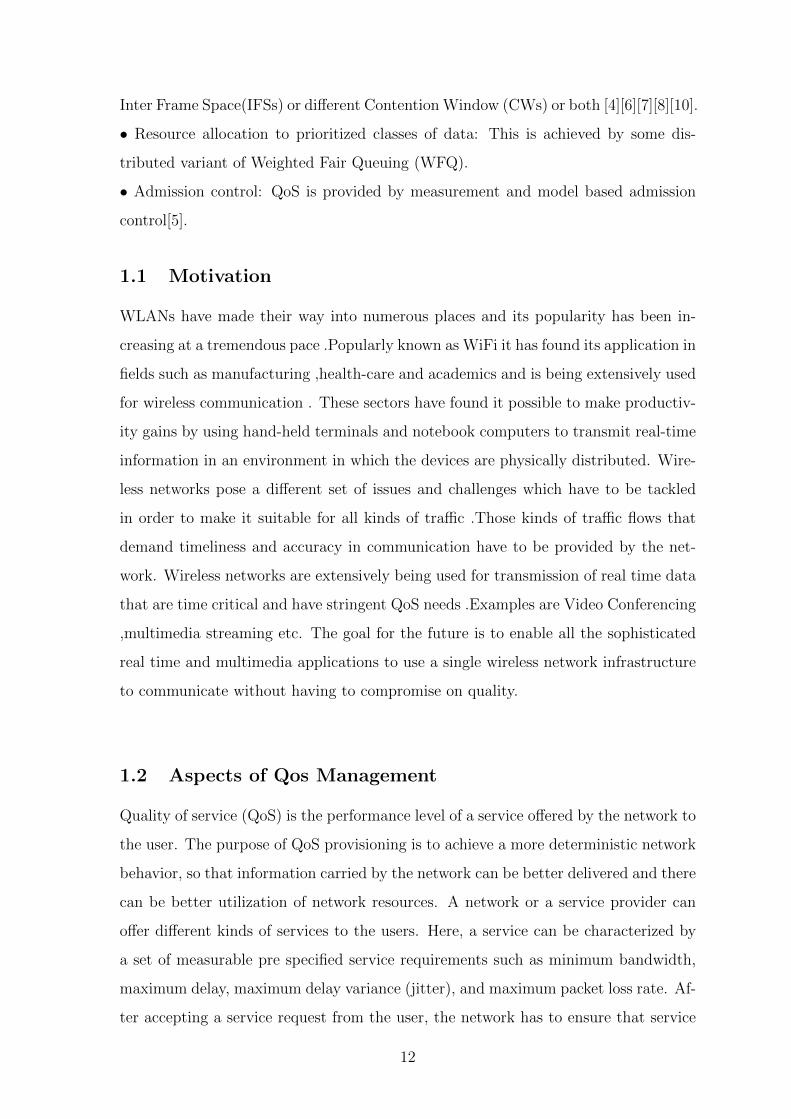
1.1 Motivation
WLANs have made their way into numerous places and its popularity has been in-
creasing at a tremendous pace .Popularly known as WiFi it has found its application in
fields such as manufacturing ,health-care and academics and is being extensively used
for wireless communication . These sectors have found it possible to make productiv-
ity gains by using hand-held terminals and notebook computers to transmit real-time
information in an environment in which the devices are physically distributed. Wire-
less networks pose a different set of issues and challenges which have to be tackled
in order to make it suitable for all kinds of traffic .Those kinds of traffic flows that
demand timeliness and accuracy in communication have to be provided by the net-
work. Wireless networks are extensively being used for transmission of real time data
that are time critical and have stringent QoS needs .Examples are Video Conferencing
,multimedia streaming etc. The goal for the future is to enable all the sophisticated
real time and multimedia applications to use a single wireless network infrastructure
to communicate without having to compromise on quality.
1.2 Aspects of Qos Management
Quality of service (QoS) is the performance level of a service offered by the network to
the user. The purpose of QoS provisioning is to achieve a more deterministic network
behavior, so that information carried by the network can be better delivered and there
can be better utilization of network resources. A network or a service provider can
offer different kinds of services to the users. Here, a service can be characterized by
a set of measurable pre specified service requirements such as minimum bandwidth,
maximum delay, maximum delay variance (jitter), and maximum packet loss rate. Af-
ter accepting a service request from the user, the network has to ensure that service
12
requirements of the users flow are met, as per the agreement, throughout the duration
of the flow (a packet stream from the source to the destination). In other words, the
network has to guarantee certain services while transporting a flow. QoS provisioning
often requires negotiation between host and network, call admission control ,resource
reservation, and priority scheduling of packets[4].
1.3 Thesis Outline
Chapter 2 focuses on the Various protocols defined in the 802.11 the and their char-
acteristics.
Chapter 3 focusses on the he QoS enhancements introduced in the 802.11e .
Chapter 4 deals with the proposals made to modify the EDCF in order to obtain a
better performance .
Chapter 5 contains the simulations results and analysis of the proposed schemes.
13

2 Chapter
Scope of IEEE 802.11The IEEE 802.11 is a set of standards pertaining to the MAC and PHY layers[3].
IEEE 802.11 refers to a family of specifications developed by the IEEE for wireless
LAN technology .The protocols used in all the 802 variations ,including 802.3(Eth-
ernet) have certain common features. The physical layer corresponds to the OSI
physical layer fairly well .But the data link layer in all the 802 protocols are split into
two sub-layers .It is upon the Media access control(MAC) sub-layer to determine how
the channel is allocated or who gets to use the channel next. Above it is the Logical
Link Control(LLC) sub-layer whose job is to make the 802 variants transparent to
the network layer[2].
2.1 The 802.11 Physical Layer
The 802.11 standard specifies three transmission techniques allowed in the physical
layer .The infrared method uses much the same technology as the television remote
controls. The other two use short range radio using techniques called FHSS and
DSSS .The original 802.11 can support upto 2 Mbps. The 802.11a uses a high speed
connection that supports upto 54Mbps .The 802.11b operates at the unlicensed ra-
dio band and supports upto 11Mbps and uses DSSS. The 802.11g operates at the
unlicensed band and provides upto 54Mbps using OFDM modulation scheme. The
IEEE 802.11n significantly improves the network throughput in comparision previous
standards, with an increase in the maximum (PHY) data rate from 54 Mbps to a
maximum of 600 Mbps[2][3].
2.2 The 802.11 MAC Sublayer
The characteristics of the 802.11 MAC sub-layer protocols is completely different from
that of traditional Ethernet mainly due to the complexity of the wireless environment
14

.With Ethernet sensing the medium and detecting collisions is far more easier. The
wireless medium has certain inherent problems such as the hidden and exposed nodes
problem. Since all stations are not within radio range of each other. In general, the
wireless networking can be implemented in two different operating modes: infrastruc-
ture and ad hoc modes. The infrastructure mode consists of an access point (AP)
co-ordinating the operation of the other nodes in the network with each client station
communicating through it. The system can be extended by having a system with
multiple access points. In the Ad-hoc mode essentially eliminates the need for an ac-
cess point. In this mode, the mobile nodes can be connected in a dynamic topology in
an arbitrary manner. All nodes of these networks behave as routers and take part in
discovery and maintenance of routes to other nodes in the network. The 802.11 defines
two modes of operation ,the first is the mandatory Distributed coordination function
(DCF) and the second is the optional Point Coordination Function(PCF)[3].The DCF
operates in the ad-hoc mode without any central coordination whereas the PCF uses
a base station or Access Point to control the activities of its cell[1][2].
2.3 The 802.11 Distributed Coordination Function(DCF):
DCF using CSMA/CA:
The CSMA/CA protocol is designed to reduce the collision probability between mul-
tiple stations accessing a medium ,MAC works with a first-in-first-out single queue
(FIFO)transmission mechanism and is shared by all the traffics .The CSMA/CA mech-
anism works as follows: when a packet arrives at the front of transmission queue ,with
the channel being found idle for an interval of time than in excess of the distributed
Inter frame Space (DIFS), the source station can transmit the packet immediately,
mean while other stations defer their transmission while asserting their network al-
location vector (NAVs)and the back-off process starts . In this process, the station
chooses a random interval ,called back-off-timer, selected from the contention win-
dow (CW): rand [O,CW]* Slot-Time .If the channel is busy, the MAC waits until the
medium becomes idle, then waits until the medium becomes idle, then defers for an
extra time interval, called the DIFS[2][6] .For each idle slot time interval, the back-off
counter is decremented. When the counter reaches zero, the packet is transmitted
15

.For each successful reception of a packet, the receiving queue station immediately
acknowledges by sending an acknowledgement (ACK) packet. The ACK packet is
transmitted after a short inter frame space (SIFS). If an ACK packet is not received
after the data transmission, the packet is retransmitted after another random back-
off. MAC parameters including, DIFS, SIFS, Slot Time , CWmin and CWmax are
dependent on the underlying physical layer address (PHY) [2][6].
RTS/CTS mechanism:
In order to get over the hidden terminal problem the RTS/CTS scheme has been
devised ,whenever a packet arrives it generates an RTS frame for destination station,
which listens for an short inter frame space (SIFS), if it found to be idle then trans-
mission of RTS, otherwise deferred until idle condition. Other stations defer their
transmission with NAV. If CTS arrives then channel is reserved for transmission of
data with a waiting for acknowledgment (ACK). If an ACK packet is not received after
the data transmission, the packet is retransmitted after another random back-off. For
each successful reception of a packet, the receiving station sends an ACK after SIFS. If
ACK arrives then it goes to the starting state, otherwise after ACK timeout it goes for
an exponential back-off .Once an error occurs, a packet has to be retransmitted by the
attempting station. Errors may be caused by many possible situations. For example,
the corresponding CTS frame may not be returned after an RTS frame is transmitted.
This may occur due to: Collision with the transmission of another station. Interfer-
ence in the channel during the transmission of other RTS/CTS frames. DCF only
supports best-effort services but does not provide any QoS guarantee for time bounded
applications such as real-time multimedia, video conferencing etc .So DCF does not
support any differentiation mechanism to guarantee bandwidth ,packet delay and jit-
ter for high-priority multimedia flows. These are the problem area in WLAN, which
needs a greater attention for research. Some parameters of CW,Back-off Algorithm
and Inter-frame spacing can be tunable to achieve the better service differentiation.
Due to the lack of a centralized controller,it is challenging to achieve quality of service
(QoS) in terms of delay, jitter ,and fairness in distributed channel access. To enhance
the IEEE 802.11 MAC, IEEE 802.11e proposes new features with QoS provisioning
to real-time applications [2][4][10].
16

2.4 The 802.11 Point Coordination Function(PCF)
The mandatory Point Coordinator Function is implemented by the Access point in
an infrastructure based network[3]. The stations requesting the PCF mode of get as-
sociated with the Point Coordinator during the contention period (CP). With PCF,
the channel access alternates between the contention free period (CFP) and the con-
tention period (CP) for the PCF and DCF modes of operation respectively.A super
frame is formed by the CP and CFP together. A beacon frame is generated at regular
beacon frame intervals called target beacon transmission time(TBTT) by the Access
Point. The value of TBTT is announced in the beacon frame.The beacon frame,
which is used to maintain synchronization among local timers in the stations and
to deliver protocol related parameters, is used to indicate the beginning of a super
frame.The channel access switches alternately between PCF mode and DCF mode,
but the CFP may shrink due to stretching when DCF takes more time than expected.
This happens when an MSDU is fragmented into several MPDUs, hence giving prior-
ity to these fragments over PCF mode of operation[4].
2.5 Inter Frame Spaces Defined In IEEE 802.11
The time interval between frames is called the IFS. A station shall determine that the
medium is idle through the use of the carrier-sense function for the interval specified.
Four different IFSs are defined to provide priority levels for access to the wireless
media; they are listed in order, from the shortest to the longest:
SIFS(Short Inter frame space):It is the shortest inter frame space used to allow
the parties in a single dialog a chance to attempt transmission .This includes allowing
the receiver to send a CTS in response to a RTS or allowing the receiver to send an
ACK in response to to a data frame.
PIFS(PCF Inter frame space):In the infrastructure mode the base station or
access point may sent a beacon frame or poll frame The PIFS shall be used only by
STAs operating under the PCF to gain priority access to the medium at the start of
the Contention Free Period.
DIFS(DCF Inter frame space): A station using the DCF shall be allowed to
17

transmit if its carrier-sense mechanism determines that the medium is idle at the
DIFS as a correctly received frame, and its back-off time has expired.
EIFS(Extended inter frame space): The EIFS is used only by a station that has
just received a bad or unknown frame to report a bad frame[2][3].
2.6 Services Offered by IEEE 802.11
Wireless LANs conforming to IEEE 802.11 must provide nine services divided into
two categories :five distribution services and four station services. The five distribu-
tion services are provided by the base stations and deal with station mobility .They
are as follows :
(i)Association: These are services used by mobile stations to connect themselves
to the base stations .It is generally used just after a station moves within the radio
range of the base station.
(ii)Disassociation: Either the base station or station can disassociate ,thus break-
ing the relationship.
(iii)Reassociation: The preferred base station can be changed by this service.
(iv)Distribution: The manner in which the route frames are sent to the base sta-
tion is determined by this service.
(v)Integration: Translations from the 802.11 format to the format required by the
destination network is handled by this service.
The four station services are as follows :
(i)Authentication: A station must authenticate itself before it is permitted to send
data because wireless communication can easily be monitored by unauthorized sta-
tions .
(ii)Deauthentication: When a previously authenticated station wants to leave the
network ,it is deauthenticated.
(iii)Privacy: For information sent over a wireless LAN to be kept confidential ,it
must be encrypted.
(iv)Data delivery: It provides a way to transmit and receive data[2].
18
3 Chapter
QoS Enhancements proposed in 802.11eThe IEEE 802.11 Task Group e (TGe) was setup to enhance the current 802.11 MAC
protocol such that it is able to support multimedia applications and overcome the
shortcoming of the DCF and PCF in providing QoS to multimedia and real time
traffic[4].
3.1 Enhanced distributed coordination function (EDCF):
Enhanced distributed coordination function (EDCF)[4][5][6][7][8][10]provides differ-
entiated and distributed access to the wireless medium. Each frame from the higher
layer carries its user priority (UP). After receiving each frame, the MAC layer maps a
frame into an access category (AC) depending upon the user priority it carries. Each
AC has a different priority or preference of access to the wireless medium. One or
more UPs can be assigned to each AC. EDCF specifies upto eight ACs to support the
user UPs. The EDCF has access parameters for controlling channel access such as
Minimum and maximum Contention Window size(CWmin and CWmax) ,Arbitration
inter frame space(AIFS) and Transmission opportunity limit(TXOP limit).The user
priorities are generally mapped into four ACs ,the packets in each AC being treated
identically. Each station contends for transmission opportunities (TXOPs) by means
of a unique set of EDCF channel access parameters with respect to the AC of the
packet to be transmitted. The TXOP is defined as an interval of time during which
a station has the right to initiate transmissions. It is characterized by a starting
time and a maximum duration called TXOP Limit. Depending on the duration of
TXOP, the station may transmit one or more MSDUs.The lowest UP assigned to the
Access category determines its priority. Whereas all DCF back-off slots begin after
DIFS from the end of the last indicated busy medium, EDCF back-off slots begin at
different intervals according to the AC of the traffic queue. The duration of the inter
frame space (AIFS[AC]) is given by:
AIFS[i] = SIFS + AIFSN*slottime
19

Each queue is associated with a specific access category (AC) and contends for the
channel independent of the others. Collisions among a single stations queues are re-
solved internally, permitting the higher priority queue to transmit and forcing the
lower priority queue to perform a collision response. Different levels of service are
provided to each AC through a combination of three service differentiation mecha-
nisms as follows:
• Arbitrary Interframe Spaces (AIFS);
• Contention Window sizes;
• Medium occupancy limits[6].
Per priority differentiation used by EDCF ensures better services to high priority
classes while offering a minimum best effort service for low priority traffic. Although
this mechanism improves the quality of service of real-time traffic, the performance
obtained are not optimal since EDCF parameters cannot be adapted to the network
conditions[7].
Figure 1: EDCF access Mechanism[4]
20

3.2 Hybrid coordination function(HCF):
The Hybrid coordination function (HCF) has features common to both EDCF and
PCF in order to provide the capability of preferential handling of MAC service data
units (MSDUs). It has upward compatibility with the both DCF and PCF. A common
set of frame exchange sequences is carried out during both the Contention Period(CP)
and the Contention Free Period (CFP). The HCF is usable only in infrastructure-based
BSSs that provide QoS, i.e., QBSSs. The HCF uses a QoS-aware point coordinator,
called HC, which is typically associated with a QAP. The HC or Hybrid Coordinator
implements the frame exchange sequences and the MSDU handling rules defined in
HCF, operating during both the CP and the CFP. It allocates TXOPs to stations
and initiates controlled contention periods for the stations to send reservation re-
quests. When the HC needs access to the wireless medium, it senses the medium.If
the medium remains idle for a PIFS period MSDU services are initiated. After the
medium is determined to be idle for at least one PIFS period the HC can start con-
tention free controlled access periods called CAPs at any time during the CP. A CAP
may include one or more TXOPs. During the CAP, the HC may transmit frames
and issue polls to stations to grant them TXOPs. At the end of the TXOP or when
the station has no more frames to transmit, the control of the medium is explicitly
handed back to the HC. During CP, each TXOP begins either when the medium is
determined to be available under the EDCF rules (EDCF-TXOP) or when the station
receives a QoS CF-Poll frame from the HC (Polled-TXOP)[4][8][10].
Figure 2: HCF access Mechanism[4]
21

4 Chapter
Further Proposals for QoS Improvement
4.1 Different back-off algorithms and Contention Window
management schemes
In the IEEE 802.11 Wireless Local Area Networks (WLANs), network nodes share a
common radio channel and hence face collisions .When a collision occurs they need to
back-off for a period of time, which is randomly selected from the Contention Win-
dow (CW).The commonly used back-off scheme is the Binary Exponential Back-off
algorithm .Since it has been seen in several studies that the BEB scheme lacks fair-
ness some other back-off algorithms have also been proposed. In the IEEE 802.11
DCF scheme, the CW is dynamically controlled by the Binary Exponential Back-off
(BEB). In the BEB algorithm, the value of the contention window is doubled every
time a node experiences an unsuccessful packet transmission .If however there is a
successful packet transmission the contention window is reset to the minimum value.
In order to avoid the contention window from growing too large or shrinking too
small, two bounds on CW are defined: the maximum contention window (CWmax)
and the minimum contention window (CWmin). However, the BEB scheme is seen
to fairness ; some nodes can achieve significantly larger throughput than others. The
fairness problem can be attributed to the fact that the scheme resets the contention
window of a successful sender to CWmin , while other nodes continue to retain larger
contention windows, thus reducing their chances of getting hold of the channel and
resulting in channel domination by the successful nodes .To address the issue of fair-
ness in BEB the MILD(Multiplicative Increase and Linear decrease) algorithm was
introduced which works as follows:
CW = min(1.5*CW;CWmax) upon collision
22

CW = CW packet upon overhearing successful packets
CW = max(CW-1;CWmin) upon success
In the LMILD scheme, each node experiencing an RTS collision increases its CW by
multiplying it by the factor mc. Any node overhearing a collision with the help of
the above-mentioned technique increases its CW by lc units(slots). When a successful
RTS transmission takes place, all nodes (including the sender, the receiver, and all
overhearing neighbors) decrease their CWs by ls units. Thus, the operation of the
LMILD algorithm can be summarized as follows:
CW= min(mc* CW; CWmax) upon collisions
CW= min(CW + lc; CWmax) upon overhearing collisions
CW= max(CW ls ;CWmin) upon experiencing or overhearing success
In the LMILD scheme, the failed senders increase theirCWs multiplicatively, while
neighboring nodes increase their CWs linearly[9].
4.2 Characteristics of the original EDCF scheme
The EDCF scheme in 802.11e protocol differentiates the traffic and maps them into
separate access category depending upon its priority. Each access category is allotted
different channel access parameters such as contention window range[CWmax[i],CWmin[i]]
and Arbitration Inter Frame Spaces(AIFS[i])for each access category denoted by
AC[i].The CW range and AIFSN values are kept low for high priority traffic and
high for low priority traffic such that the high priority traffic may have to wait less
for getting a chance to transmit [5][8].
The values of the parameters for the different Access Categories are as follows:
AC[3]→ CWmin=3;CWmax=7;AIFSN=2;
AC[2]→ CWmin=7;CWmax=15;AIFSN=2;
AC[1]→ CWmin=15;CWmax=1023;AIFSN=7;
AC[0]→ CWmin=15;CWmax=1023;AIFSN=16;
Where; AC[0] refers to background traffic ,AC[1] refers to best effort traffic ,AC[2]
refers to video traffic and AC[3] refers to voice traffic. By using different values of
these parameters it is ensured that the high priority video and voice traffic have to
wait less in order to access the medium. Since these are delay sensitive traffic it is
23

essential that the delay and jitter are kept at minimum.
Predefined values of CWmin and CWmax and a binary exponential backoff is used
for each access category is used.
CW[i] = max(2*CW[i],CWmax[i]) On collision;
CW[i] = CWmin[i]; On Successful Transmission;
Where ; AC[0] refers to background traffic ,AC[1] refers to best effort traffic ,AC[2]
refers to video traffic and AC[3] refers to voice traffic. By using different values of
these parameters it is ensured that the high priority video and voice traffic have to
wait less in order to access the medium. Since these are delay sensitive traffic it is
essential that the delay and jitter are kept at minimum.
The IEEE 802.11MAC layer DCF of and the 802.11e EDCF follow the binary expo-
nential back-off algorithm in which the Contention Window for that particular Access
Category(AC[i]) is is set to double its value whenever there is a transmission failure
till it reaches the maximum value that is CWmax[i] . Whenever there is a success-
ful transmission the CW[i] is reset to its minimum value CWmin[i]. It assumes that
once a successful transmission occurs the factors causing failure of transmission no
longer exist. This may not be the case always and it may result in a higher rate of
collisions causing degeneration of performance .Further the BEB scheme suffers from
fairness issues under high traffic load and low throughput problems when network
size is large. The fairness problem occurs due to the fact that the scheme resets the
contention window of a successful sender to CWmin , while other nodes continue to
maintain larger contention windows[9].
4.3 Proposed Modification
We have proposed a scheme in which the increasing of the contention window in case
of a transmission failure as well as its resetting is done in a gradual and non-uniform
manner in the Contention Window range. The manner in which the Contention win-
dow is made to vary depends upon the kind of traffic .For high priority traffic the
Contention Window is varied linearly in case of a collision till it reaches a certain
value after which it is increased at a faster rate. Same is the case for resetting the
contention window. Linear increase in contention window size helps reducing the de-
24
lay difference between packets sent from different rounds of back-off, while reducing
the probability of collision in subsequent rounds[5].
4.4 Module Description
In the above scheme the module Increase Contention Window which is called when-
ever there is a unsuccessful transmission occurs performs the following functions .First
it checks the access category of the traffic flow .If it is high priority voice or video
traffic it checks its current CW[i] value .If it is less than twice that of its CWmin[i]
,its CW is incremented linearly till it reaches twice the CWmin[i] .Beyond that the
value of CW[i] is increased at a faster rate by multiplying with a factor of 1.5.The
justification for this kind of modification is that the probability of three or more con-
secutive collisions is less [5] hence linear increase of the CW will not affect the overall
performance .Moreover the CWmin[i] value of the high priority traffic is kept low .If
there are too many collisions the CW starts to increase at a faster rate once CW[i]
becomes greater than 2*CWmin[i]. for low priority traffic the CW[i] value is increased
consistently by multiplying by a factor of 1.5.
Increase Contention Window(AC[i]):
Begin
If(i≥2) //For video and voice traffic
If(CWi<2*CWmin)
CW[i]=min(CW[i]+1,2*CWmin[i])
Else
CW[i]=min(CW[i]*1.5,CWmax[i])
Endif
Elseif(i≥0 and i<2 ) //For best effort and background traffic
CW[i]=min(CW[i]*1.5,CWmax[i])
Else (Display Invalid Access category)
Endif
End
25

4.5 Module Description
The above module Reset Contention Window which is called whenever there is a suc-
cessful transmission performs the following functions .Instead of immediately resetting
the CW[i] value to CWmin[i] for a particular Access Category in case of a successful
transmission it checks its priority .If it belongs to video or voice traffic the Contention
window is linearly decremented if CW[i] is less than twice that of CWmin[i] otherwise
it is decreased by a factor of 0.5 as in the slow decrease scheme mentioned in[7] .For
all other traffics the CW[i] is decreased by 0.5 till it reaches the CWmin[i] .This slow
decrease scheme includes linear decrease for high priority traffic[7][9].
Reset Contention Window(AC[i]):
Begin
If(i≥2) // For video and voice traffic
If(CW[i]<2*CWmin[i])
CW[i]=max(0.5*CW[i],2*CWmin[i])
Else
CW[i]=max(CW[i]-1,CWmin[i])
Endif
Else(i≥0and i<2) //For best effort and background traffic
CW[i]=max(0.5*CW[i],CWmin[i]);
Else(Display Invalid Access Category);
Endif
End
26

5 Chapter
Simulations and Result
5.1 Simulations
We have implemented the above proposed modifications and compared the results to
the existing EDCF. All the simulations have been done using the Qualnet network
simulator designed by Scalable Networks Inc. For carrying out the simulation we
have taken 50 nodes in a 1000mX1000m area. An uniform distribution model has
been followed. The nodes are fully independent and are operating in a distributed
environment. The nodes are operating in an ad-hoc mode or IBSS mode without any
central Access Point to coordinate channel access, Ten nodes have been connected in a
manner such that each node sends and receives a pair of high priority voice traffic and
a low priority best effort traffic. Constant Bit Rate connections have been used for
each of the connections. For the voice traffic 64 byte packets are sent at an interval of
20 millisecond giving a data rate of 25.6 kbps .For the best effort traffic 512 byte data
packets are sent at an interval of 16 milliseconds giving a data rate of 256 kbps. The
no of packets of each of the two traffic are increased from 20 to 160 and the scenario
is executed. Finally graphs for the average value of the Throughput ,Packet Delivery
Ratio ,and jitter of the high priority voice traffic in the presence of low priority best
effort traffic are plotted against the no of packets sent. The performance of proposed
modification can be compared with the existing EDCF scheme. Simulation have also
been carried for mobile stations .For this a random waypoint mobility model is used
with a pause time of 50 seconds.
27

SCENARIO SCREEN SHOT
Figure 3: Screen Shot of Scenario
5.2 Results
The scenario described above was run for no of the packets varying from 20 to 160
Packets and the average value of the performance parameters are taken for the ten
stations .The experiment is carried out once for the existing EDCF scheme and once
for the proposed scheme. The performance parameters are then compared .
28

5.2.1 For Static Nodes
When the results are plotted for static nodes the following graphs have been obtained:
Figure 4: Packet Delivery Ratio VS No. of Packets sent
The above graph shows that after the proposed modification have been applied there
is a gain in the average packet delivery ratio .Packet delivery is defined as the ratio of
packets received by receiver to that of the packets sent by the sender. The gain ob-
tained is consistent for any number of packets. This shows that our proposed scheme
has reduced the rate of collisions and thereby has brought down the rate of packet
loss .This validates our claim that the gradual contention window variation scheme
does indeed bring down the packet collision rate.
29

Figure 5: Throughput VS No. of Packets sent
When the proposed scheme is applied it is observed that the average throughput
suffers in our scheme when the number of packets is less than a certain maximum
value. From the above graph the value is found to be around 90 packets per station
for the high priority data. When the number of packets increases beyond a certain
value we observe an improvement for our scheme. This indicates that the proposed
Contention window management scheme gives a better throughput performance at
high traffic condition than at low traffic conditions. At high traffic conditions colli-
sion rate becomes higher. Thus we can conclude that our scheme is able to reduce
the packet loss due to collisions to give a better throughput at higher traffic.
30

Figure 6: Jitter VS No. of Packets sent
In the above graph the average jitter of the network shows a steady improvement
for any number of packets when the proposed scheme is applied .Jitter indicates the
variation in delay experienced in a network. This indicated that the gradual increase
and decrease of the Contention Window causes the delay between packets to be more
uniform thereby reducing the average jitter. Since the time for which the stations
defer transmission on suffering collision varies less than in the Binary Exponential
back-off followed by the EDCF scheme the proposed scheme in giving a reduced av-
erage jitter value for the network.
31

5.2.2 For Mobile Nodes
The following results are obtained when mobile nodes are used instead of static nodes:
Figure 7: Packets Delivery Ratio VS No. of Packets sent
The graph obtained shows that after the proposed modification have been applied
there is a gain in the packet delivery ratio similar to what was obtained for static
nodes .The gain obtained is also consistent for any number of packets. This shows
that our proposed scheme has reduced the rate of collisions and has brought down
the rate of packet loss .Given the fact that mobile nodes suffer higher packet loss and
transmission failures our proposed scheme performs well in maintaining a consistent
packet delivery ratio for mobile nodes .
32

Figure 8: Throughput VS No. of Packets sent
As in case of static nodes the average throughput suffers in the proposed scheme
when the number of packets are less but it improves as the number of packets in-
creases beyond a certain value . In this case it is about 80 packets per station for
high priority traffic .However the gain in average throughput of the network is not
as impressive as the static nodes. At high traffic conditions collision rate becomes
higher. It becomes still higher for mobile nodes .However we can conclude that the
proposed scheme is able to reduce the packet loss to some extent for mobile nodes
and hence gives a better throughput at higher traffic.
33
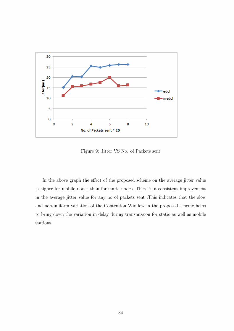
Figure 9: Jitter VS No. of Packets sent
In the above graph the effect of the proposed scheme on the average jitter value
is higher for mobile nodes than for static nodes .There is a consistent improvement
in the average jitter value for any no of packets sent .This indicates that the slow
and non-uniform variation of the Contention Window in the proposed scheme helps
to bring down the variation in delay during transmission for static as well as mobile
stations.
34

6 Chapter
Conclusion and Future work
6.1 Conclusion
In this thesis we studied the various QoS enhancement schemes in the MAC layer for
wireless networks .We have further proposed a modification to the existing 802.11e
EDCF by varying the Contention Window of high priority traffic in a gradual and non-
uniform manner and then demonstrated the effect of the proposed scheme by carrying
out the simulations and compared the results with the existing EDCF scheme .From
the simulations and results we conclude that the proposed scheme for increasing and
resetting the contention window results in the gain in some of the performance param-
eters : The average packet delivery ratio shows a consistent improvement for both
static and mobile nodes .The average throughput shows improvement when higher
number of packets are sent for both .The average jitter is less for both static and
mobile node. Thus we see that the slow , non-uniform increase and decrease of the
contention window for high priority does indeed results in an improvement for these
network performance parameters.
6.2 Future Work
The Back-off algorithm and the Contention window variation schemes have a strong
impact on the performance of a network and in providing QoS for particular classes of
traffic. In this thesis we have proposed a scheme for varying the CW which resulted
in the improvement of some of the performance parameters .Further study may be
done to tune the scheme further to get even better results for parameters such as mean
delay .The impact of network environment may be studied and mathematical analysis
may be done to determine the optimal factors by which the CW can be increased or
decreased to improve the performance of the scheme even further.
35
References
[1] B.S.Manoj and C.Siva Ram Murthy, Ad-Hoc Wireless architectures and Protocols:
Pearson, 1st edition.
[2] Andrew S, Tanenbaum,Computer Networks :Prentice hall India,4th Edition.
[3] IEEE std 802.11.Wireless LAN Medium Access Control(MAC) and Physical
Layer(PHY) Specifications.1999
[4] T.Bhimarjuna Reddy,I.Karthigeyan,B.S.Manoj,C.Siva Ram Murthy.Quality of se
rvice provisioning in ad hoc wireless networks:a survey of issues and solution.
Journal of ad hoc networks, 4(1):83-124,2006.
[5] Mayank Mishra and Anirudha Sahoo. An 802.11 based MAC Protocol for Pro-
viding QoS to Real Time Applications. IEEE 10th International Conference on
Information Technology, 6:615-619,2007
[6] Jeffrey W. Robinson, Student , and Tejinder S. Randhawa. Saturation Throughput
Analysis of IEEE 802.11e Enhanced Distributed Coordination Function. IEEE
journal on selected areas communications, 22(5):June 2004.
[7] Lamia Romdhani, Qiang Ni, and Thierry Turletti.Adaptive EDCF: enhanced ser-
vice differentiation for IEEE 802.11 wireless ad-hoc networks .Wireless Commu-
nications and Networking, 2003. WCNC 2003. 2003 IEEE,2(1):1373-1378,March
2003.
[8] J. N. Al-Karaki and J. M. Chang. Quality of Service Support in IEEE 802.11 Wire-
less Ad Hoc Network. Wireles Communications and Mobile Computing,2(4):265-
281, July 2004.
[9] J. Deng and P. K. Varshney and Z. J. Haas, A New Backoff Algorithm for the IEEE
802.11 Distributed Coordination Function, Proc. of Communication Networks and
Distributed Systems Modeling and Simulation(CNDS ’04): 256-274,January 18-21,
2004, San Diego, CA, USA.
[10] IEEE std 802.11e-2005.Amendment 8: Medium Access Control (MAC) Quality
of Service Enhancements .September 2005.
36