study of weldability utilizing laser welding for
TRANSCRIPT

Study of Weldability Utilizing Laser Welding for
Thermoplastics Modified with Different Additives with
Respect to Production Requirement of Injection Moulding
Master thesis
Study programme: N2301- Mechanical Engineering
Study branch: 2301T048 – Engineering Technology and Materials
Author: Devang Kanaiyalal Prajapati
Supervisor: Ing. Pavel Brdlik, Ph.D.


Declaration:
I hereby certify that I have been informed the Act 121/2000, the Copyright Act of the Czech
Republic, namely §60 – Schoolwork; applies to my master thesis in full scope.
I acknowledge that the Technical University of Liberec (TUL) does not infringe my copyrights
by using my master thesis for TUL’s internal purposes.
I am aware of my obligation to inform TUL on having used or licensed to use my master thesis;
in such a case TUL may require compensation of costs spent on creating the work at up to their
actual amount.
I have written my master thesis myself using literature listed therein and consulting it with my
thesis supervisor and my tutor.
Concurrently I confirm that the printed version of my master thesis is coincident with an electric
version, inserted into the IS STAG.
Date:
Signature:

Annotation:
The work deals with laser welding of polypropylene (PP) matrix based samples with or without
chosen additives (carbon black and glass fibre) and investigation of the overall effect on
weldability. Furthermore, it evaluates how additives addition affected mechanical properties of
welded joints. All the samples were produced by injection moulding technology. Once the
samples were welded, they were subjected to tensile testing.
The main challenge was to find appropriate process parameters (laser power and velocity)
of the laser machine, so that good weld quality (visual and mechanical) can be achieved. The
achieved result shows the impact of carbon black and glass fibre on the weldability.
Keywords:
through transmission laser welding, polypropylene, carbon black, glass fibre.

Acknowledgement:
Foremost, I would like to say special thanks to my honourable professor Ing. Pavel Brdlik PhD.
because, he never stopped believing in me during this whole experimentation period. Though
there were some obstacles came while experimenting, he was always beside me. So I would like
to express my deep gratitude for his generous support.
Besides, it is my privilege to mention the name of my in-charge and supervisor from
company Magna, ‘Mr. Ondřej Liška’. I would like to thank him for his patience, motivation, and
immense knowledge. His guidance helped me in all the time of research and writing of this thesis.
Next, I feel quite grateful and proud to have such a wonderful family. For finishing this
thesis successfully, only one sentence from my parents was enough for me: "We are always with
you no matter whatever happens". That worked as an unending fuel for me.
I genuinely would like to express my gratitude towards the GOD. I think without his/her
blessings and grace, it would not be possible to accomplish my work.
Last but not least, I would like to thank my fellows, who had given me some useful
advises: Rushabh Patel, Hardik Prajapati, Anand Bharucha, Nirav Sailor, Rakesh Soni.
This publication was written at the Technical University of Liberec as part of the Student
Grant Contest "SGS 21122" with the support of the Specified University Research Grant, as
provided by the Ministry of Education, Youth and Sport of the Czech Republic in the year 2018.

6
Contents
1. Introduction……………………………………………… 9
2. Theoretical part…………………………………………. 10
2.1. Factors affecting laser welding…………………………. 16
2.2. Direct laser welding……………………………………… 17
2.3. Through transmission laser welding…………………… 19
2.4. Materials suitability for laser welding…………………... 22
2.4.1. Semi crystalline thermoplastics………………………… 23
2.4.2. Amorphous thermoplastics……………………………… 26
2.5. Additives…………………………………………………… 28
2.6. Additives to improve absorption………………………… 30
2.6.1. Carbon black……………………………………………… 30
2.6.2. Inorganic pigments……………………………………….. 33
2.6.3. Special Organic dyes……………………………………… 35
2.7. Joint geometry design…………………………………….. 37
3. Practical part……………………………………………… 40
3.1. Used laser welding machine……………………………… 40
3.1.1. Control unit………………………………………………….. 42
3.1.2. Clamping unit………………………………………………. 43
3.2. Test specimen production………………………………… 44
3.2.1. Material specification……………………………………… 44
3.2.2. Test specimens…………………………………………….. 45
3.2.3. Injection process…………………………………………… 46
3.2.4. Sample combinations for experiment……………………. 47
3.3. Welding process…………………………………………… 50
3.3.1. Welding of PP for all the conditions……………………… 50
4. Evaluation and discussion……………………………… 53
4.1. Welding of PP samples…………………………………..... 53
4.2. Welding of PP without glass fibre with optimized
clamping………………………………………………………
54
4.3. Evaluation of PP with 10% glass fibre…………………….. 58
4.4. Evaluation of PP with 30% glass fibre…………………….. 60
4.5. Evaluation by breaking force……………………………….. 63
5. Conclusion…………………………………………………… 67
6. Reference…………………………………………………….. 70

7
List of abbreviations and symbols
NIR Near Infrared Region
TTLW Through Transmission Laser Welding
DC Direct Current
Nd: YAG laser Neodymium-Doped Yttrium Aluminium Garnet
GaAlAs Gallium Aluminium Arsenide
GaAsP Gallium Arsenide Phosphorous
InGaAsP Indium Gallium Arsenide Phosphorus
α Amount of absorbed rays
δ Amount of reflected rays
ϒ Amount of transmitted rays
α₁ Polar surface free energy of material 1
α₂ Polar surface free energy of material 2
ϒ₁ Heat expansion co-efficient of material 1 under constant pressure
ϒ₂ Heat expansion co-efficient of material 2 under constant pressure
K+ Scattering constant
N Number of scattering crystalline phases;
V Volume of crystalline phases
Λ Wavelength of radiation
N Number of scattering crystalline phases
ϱ Cross-section of scattering particle
PMMA Poly(Methyl Meth-Acrylate)
PVC Polyvinylchloride
ABS Acrylonitrile Butadiene Styrene
HDPE High Density Polyethylene
PS Polystyrene
PP Polypropylene
PA Polyamide
PC Polycarbonate
UV Ultra Violate
ITO Nano-Indium Tin Oxide
NC Numerical Control
CNC Computer Numerical Control
MFI Melt Flow Index
GF Glass Fibre
CB Carbon Black

8
TP Transparent Part
AP Absorption Part
Yb: Fibre Ytterbium Fibre
CO2 Carbon dioxide
E1 and E2 Energy levels of photon
h Plank constant
v Angular frequency
TiO2 Titanium oxide
SnO2 Tin oxide

9
1. Introduction
Manufacturing of plastic parts and their application is continuously growing in all industries.
Sometimes the production of complex geometry becomes complicated therefore, it is necessary
to make the component in two parts and then join those two plastic parts using conventional
methods (hot gas welding, extrusion welding) or non-conventional methods (ultrasonic welding,
laser welding). Welding using light sources have been developing rapidly in last 50 years and it
is still inclined to new benchmarks and developments. After its inclusion into the industry,
conventional joining methods were mostly replaced by these methods because these methods are
suitable for mass production [1]. Laser welding method is one of these methods. Laser welding
process and its use were initially demonstrated in 1970’s. During this period, there was only one
laser welding process used, which was direct laser welding by CO2 laser [1], [2]. Afterward, in
1985, another laser welding method was patented by Toyota, Japan. They welded two plastic parts
with a near infrared laser (NIR), which was Nd:YAG laser. This method was named through
transmission laser welding (TTLW) [2]. The first TTLW method was patented by using carbon
black, as an additive to change the absorption properties of the absorptive part. From 1990, the
usage of laser welding as a joining method had already started to increase day by day and in the
current scenario, it is one of the most versatile methods for joining two plastic parts. Nowadays,
the development is inclined towards increasing weldability of different thermoplastics, so that can
be easily welded. If carbon black is applied on the absorptive part as an additive for increasing
absorption, the colour of the absorptive part could be changed. So this is the problem of using
carbon black as an additive. But still, there is an advantage of using carbon black as an additive
because it could evoke the change in the laser welding’s process parameters (decrease in the
power or increase in the velocity). Laser welding is commonly applied, where the part geometry
is flat and easily weldable. But it is difficult to weld uneven geometry rather than a flat one.
TTLW is applicable in many fields, like automotive, medical and consumer goods packaging. In
the automotive sector, it is used for welding of head and tail light, under hood components and
instrument panels [4]. Before laser welding, for joining head and tail lights, hot plate welding was
used. But hot plate welding was prone to flash generation in between and caused internal stress
also. For these reasons, hot plate welding was replaced with laser welding [5].
In this thesis, the main focus of work was on how to increase the weldability of thermoplastic
parts of different thicknesses by using some kind of additives (carbon black, glass fibre). It was
also important to figure out how these different additives form the mechanical bonding between
specimens. Then, the mechanical quality of weld joint was measured with the tensile testing
machine.

10
2. Theoretical part
Laser welding is one of the most versatile joining methods, which could be utilized for joining a
wider range of plastic products. The product thickness can vary from very low (film sheets of
0.01 – 0.1 mm) to a very high thickness (50 mm). Laser welding technique possesses
characteristics of high accuracy, high precision and lower distortion, which leads to better
performance of components and high weld quality. For keeping high tolerance in the components,
generation of laser beam plays a consequential role. So the spot size of laser beam should be very
small. Normal white lights produce incoherent beam (figure 1), which results in wider spot size.
On the contrary, it is important for laser resonator to create a particular coherent laser beam [6].
For the creation of coherent laser beam, some amount of excitation in the energy state of atoms
or electrons is the key thing.
Figure 1 Coherency of laser light [7]
All the molecules and atoms have a certain amount of energy states and energy levels.
Amongst them, electrons could peregrinate through these energy levels and transmit their gained
energy in terms of photons. For the generation of photons, electrons must travel to and fro from
ground level to excited level and vice-versa (figure 2). Predominantly, the electrons lie in the
ground state under normal condition. But if the electron is in exhilarated condition somehow with
an energy E2, it could go to the ground level all of a sudden and reduce its energy level to E1
(figure 2). During reducing the energy level from E2 to E1, it liberates photon. This process is
called spontaneous emission and this will exhibit fluorescence light [8], [9]. Energy produced by
this emission will be:
E2−E1=hv; (1)
Where, E2−E1 = Energy of photon (J);
h = plank constant = 6.62 × 10⁻³⁴ (m2 * kg / s);
v = angular frequency (rad/s).

11
Figure 2 Spontaneous emission
When the electron is at the excited state with energy E2 and photon is imparted on it from
outside source, the electron will relinquish the energy in terms of another photon. Thus, there will
be two photons engendered: one is being imparted by photon and another is in pursuance of
released energy by an electron. Both of these photons have the same frequency, the identical
direction of polarization and homogeneous direction of propagation (figure 3). This process of
photons generation is called stimulated emission because the atoms will absorb the incident
energy [8], [9]. This is how all the generated photons will be coherent and this is the crucial
property needed for the laser to be amplified.
Figure 3 Stimulated emission
Generation of laser beam requires one optical resonator (laser cavity) and one laser gain
medium. Laser cavity is comprised of two mirrors from which the laser could be
polarized (figure 4). Laser gain medium is made of a laser crystal (pumping source) which is
needed for the amplification of laser [8]–[10]. Laser crystal works as a pump so that it can amplify
laser (figure 4).

12
Figure 4 Laser generation device
There are different kind of lasers, which are currently used in practice. Laser generation
principle remains kindred for all of them. The only difference between them lies in the place that
they use distinct laser pumping sources and active medium [4], [10]. Variants of lasers, which are
used in industries are described briefly below:
CO2 laser
CO2 laser is effective for generating beam wavelength at about 10,600 nm. The CO2 laser
generator composed of a glass tube with gas inlet and outlet (figure 5). In a glass tube, the gas
mixture of nitrogen, helium and carbon dioxide (the highest content) is used. For electrical DC
discharge, the tube has anode and cathode locale. The glass tube is sealed off from atmospheric
pressure by two Zn-Se windows, which are transparent to CO2 laser radiation. At the point when
the release is occurring between anode and cathode, the coalescence of all of the gases is streamed
as a laminar flow [4].
Figure 5 CO2 laser construction [4]

13
When the laser power is switched on, it causes electrical discharge amongst anode and
cathode. By this phenomena, nitrogen molecules start to vibrate and activate their energy by linear
molecular oscillation. These activated nitrogen particles then collide with carbon dioxide
molecules, transferring their activation energy to CO2 particles. Now, these excited CO2
molecules lower their energy by emission of photon with wavelength of 10,600 nm. After
emission of photon, CO2 particles strike with helium particles and goes to the ground energy level,
again getting ready to collide with nitrogen particles. Generated laser could only pass through the
semi-transparent front mirror, as the back mirror is consummately opaque. The laser power
generated by this system could reach upto 500 W. As the generated power is quite high, the
penetration depth of laser beam in material is very low (10 – 100 μm). For this reason, CO2 laser
could not be utilized for thick plastic welding. It is applicable only for joining of thin
thermoplastic films [4].
Nd:YAG laser
Nd:YAG is a neodymium-doped Yttrium aluminium garnet solid state laser. Nd:YAG laser
commonly produces laser light radiation at 1064 nm wavelength, which comes under near-
infrared region (NIR). Some of the Nd:YAG lasers could also deliver laser at some extraordinary
wavelengths like 1440 nm, 1320 nm, 1120 nm and 940 nm [11], [12]. The working principle of
Nd:YAG laser is demonstrated in Figure 6. Nd:YAG laser rod is placed between two pumping
sources in double elliptical cavity. This elliptical cavity is polished like a mirror. Pumping lamps
aid to engender photons. These generated photons then target on the Nd:YAG laser rod for
amplification. Once these photons are amplified, they are converted into coherent laser beam [4].
Figure 6 Nd:YAG laser schematic diagram [4]
14
Before this generated laser beam perforates the parts, it has to travel between two mirrors
(figure 6). Both of these mirrors are coated with silver colour. One of the mirrors is thoroughly
silvered, while another is partially coloured. The fully coloured mirror will reflect the laser
radiation completely. While another mirror, which is partly coloured, will reflect some amount
radiation to the target material [4], [7].
Above mentioned lamp pumped Nd:YAG laser has a drawback of poor electrical
efficiency (< 4%). Due to low efficiency, any further developments in Nd:YAG lasers had been
ceased. Now, the progress is slanted towards the laser diode pumped YAG lasers, which is
competent to generate power up to 6-10 kW [2]. Contrasted with a CO2 laser, Nd:YAG laser has
capacity to penetrate deeper in materials, as it can generate lower wavelength (1064 nm). Except
for plastic production, Nd:YAG laser could also be used for engraving, etching and welding of
metals in medical, aerospace and many else industries [13], [14].
Diode laser
Diode lasers are the most used laser source these days. The root cause behind prodigious
applicability of diode laser is that, it could operate in wavelength range from 800 to 2000 nm.
Diode laser generates laser power from mW to several kW. For joining plastic components,
commonly used diode laser wavelengths are 808 nm, 940 nm and 980 nm since plastic welding
with longer wavelength is being investigated [4]. Generation of wavelength depends on the
utilized semi-conductors materials (GaAlAs, GaAsP or InGaAsP), which works as an active
medium for diode laser.
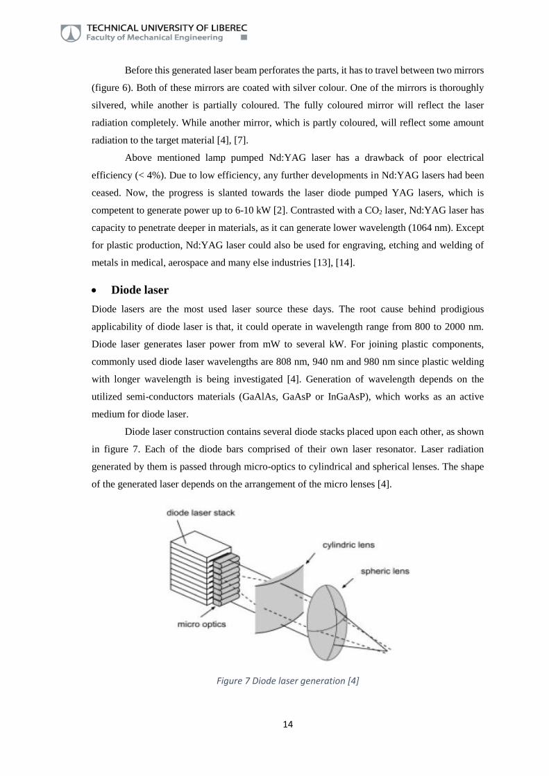
Diode laser construction contains several diode stacks placed upon each other, as shown
in figure 7. Each of the diode bars comprised of their own laser resonator. Laser radiation
generated by them is passed through micro-optics to cylindrical and spherical lenses. The shape
of the generated laser depends on the arrangement of the micro lenses [4].
Figure 7 Diode laser generation [4]

15
For emission of laser with various wavelengths, an electric current must be directly
applied to the diodes. Laser generated by diode has lower beam quality than other laser sources
like Nd:YAG or fibre laser. This could result in weak spot size on the material. On the contrary,
diode laser has lower purchase and running cost, which are noticeable reasons to surmount the
problem of lower beam quality [1], [4].
Taking heat into consideration, diode laser is proficient of generating local heat input to
the material, which warm ups the part within short time period. Due to this propriety, diode laser
source is used for welding plastic products in the fields of packaging, electronics and automotive
industries [15]–[17].
Fibre laser
Fibre laser source is capable of generating wavelengths in the range of 1000 – 2100 nm (relies on
the utilized active medium). For welding of plastic parts, most used wavelength in industries is
proximately about 1100 nm, as it could facilely replace Nd:YAG laser source (1064 nm). Fibre
laser has quite similar beam quality as Nd:YAG laser, however it has eminently higher electrical
efficiency (up to 30%), which is approximately 7 times higher than Nd:YAG laser source [1], [4].
Fibre laser unit is comprised of glass fibre with very small diameter, which is doped with
silica core. This doped silica core works as an active medium for laser generation. Silica core is
cladded with two layers: one layer works as waveguide for optical pumping, while another layer
ascertains the total reflection of the optical radiation. For optical pumping, diode laser source is
directly connected to silica cladding of glass fibre. Now the generated optical radiation will travel
along the length of glass fibre for generating laser radiation. For laser radiation pumping, two
types of setups could be used (figure 8). End pump configuration has a diode laser directly
connected to one of the cessations of glass fibre. Another type is fibre pump configuration, which
uses plenty of fibre coupled diode lasers. These in-coupling fibre guides are connected to the
cladding of the glass fibre. These fibre guides directly transfer pumping radiation into the
cladding [4].

16
Figure 8 Fibre laser diagram [4]
For joining the plastic materials, usage of fibre laser is continuously increasing due to its
high efficiency. Fibre laser is used for very precision welding, thin film joining, large parts and
textiles [1].
2.1. Factors affecting laser welding
At the point when a beam of laser strikes on a surface of any products, it has a characteristic
tendency to behave in a three ways. The ray could either being absorbed, transmitted or reflected
[1]. Corresponding absorption quantity could be counted by following equation [4]:
α+ δ+ ϒ = 100; (2)
α = amount of absorbed rays (%);
δ = amount of reflected rays (%);
ϒ = amount of transmitted rays (%).
These characteristics are dependent on the several factors [1], [2]:
Laser wavelength λ;
Laser beam intensity;
Clamping pressure;
Welding time or rate of the laser beam movement.
Laser beam intensity is directly proportional to the generated thermal energy
(temperature). If the temperature of a laser beam is sufficiently high then the material at interface
could melt effortlessly. Therefore high intensity laser beam could expeditiously cover the entire
part geometry. But if the temperature is excessively high, then there could be an issue of material’s

17
thermal degradation. On the other hand, if the beam intensity or temperature is too low, then it
could be the reason of very low welding productivity, lower weld quality or sometimes even the
weld will not be generated. Likewise, if the applied clamping pressure is much higher, then there
could be a stoppage of chain dispersion, which could decrease the quality of joints [1]. Despite of
this, if the pressure is too low, it could create air gaps, which results in deficient surface wetting.
Weld time has nearly similar effect as of the temperature [1], [2]. If the temperature of a laser
beam is high, then it takes less time to pass through entire geometry, as the part would be heated
rapidly. While if the temperature of laser beam is low, then the interface between two parts would
take a longer time to melt. It outcomes in longer weld time. Absorption and transmission of the
beam in the material are vigorously affected by wavelength of laser beam, which could affect the
weldability. According to this beam wavelength, radiation could be divided into two parts:
o Short wavelength radiation: This wavelength is lesser than 350 nm, which comes under
ultraviolet beam region. In this radiation region, imparted photon energy is quite high, so
that it directly breaks the chemical bonds present in the material. This process is known as
photolytic process. For this reason, this beam could be utilized for ablation or for chemically
curing the material [1].
o Long wavelength radiation: This wavelength is higher than 350 nm and it comes in the
infrared region (CO2 laser, fibre laser). As the radiated wavelength is high, it raises the
temperature quickly, which directly involves heating of the surface. This process is known
as pyrolytic process. This wavelength interaction causes heat (higher surface absorption and
lower transmission) in the material surface so, it is utilized for melting or welding of parts
[1].
According to optical characteristics and wavelength of laser beam, laser welding of polymers is
divided in two parts: Direct laser welding and through transmission laser welding (TTLW).
2.2. Direct laser welding
The principle of direct laser welding technique is transformation of laser energy on surface of
joining parts to heat and creation of ample pressure to join them. Direct laser welding technique
could use beam wavelength in range of 2000 – 10,600 nm. The higher efficiency of laser energy
transition to surface of material will be achieved by higher applied wavelength. Consequently,
the common wavelength used in technical application is 10,600 nm. In direct laser welding, CO2
laser, fibre laser or Holmium YAG laser could be applied. The CO2 lasers operate at higher
wavelengths than fibre laser or Holmium YAG laser. Therefore it has potential for wider use. Due
to low heat conductivity of plastic materials the absorbed heat energy cannot penetrate deeper
into material. This is reason why direct laser welding techniques is applicable only to thin

18
thermoplastics like films and sheets [4]. The example of principle the thin film direct laser
welding technique is shown in the figure 9.
Figure 9 Direct laser welding [2]
At early stages, butt welding of two thick plastic components was performed by using
CO2 laser source. Rather than applying laser beam directly on the surface, one special type of
beam bending mirror is used to turn the laser beam on surface (figure 10). When the laser beam
heats the surface sufficiently, mirror is taken out and both parts are pressed together to compose
a consistent joint. This method was not able to make a colossal impact in industries because of
high investment cost [4].
Figure 10 Laser butt welding by CO2 source

19
The advantages of direct laser welding could be summarized as follows [1], [18], [19].
Direct laser welding is a non-contact method, so there is no chance of wear and abrasion
as in ultrasonic welding and friction welding;
By this welding technique, thermal and residual stress in the product will be very less, as
the heat affected zone is negligible;
Process is vibration free because, the heat will be generated by concentrated laser wave
and conduction of molecules inside the part;
There is no chance of flash generation as in hot plate welding because direct laser welding
is a non-contact type of technique;
Bond strength between two parts is very high and stability of welded area is for long term;
Laser welded part has low rate of rejection due to high precision and accuracy;
Besides having these advantages, direct laser welding technology also has some limitations [1],
[18], [19]:
The beam wavelength, which strikes the surface of the material, is quite high (10.6 μm).
Due to this, the generated temperature could also be high and it could cause material
degradation;
Application area of direct laser welding technique is limited to only thin thermoplastic
films welding.
2.3. Through transmission laser welding
Through transmission laser welding (TTLW) is a kind of welding procedure, where one of the
parts ought to have transmitive property to the laser beam, while another one should be capable
to absorb the incident laser beam and transmit it in the form of heat, as schematized in figure 11.
Both the parts are firmly in contact with one another by some clamps, which applies adequate
welding pressure to them. Laser beam first passes through the transmission part to the absorption
part. As the absorption part is doped with some kind of additives, which absorbs the laser beam
energy and convert it into melt. As a consequence and due to heat transfer process, transmission
part also commences to melt. As mentioned above, both these parts are firmly connected together
by some clamping means. Due to this, welding procedure takes place between both the parts [1],
[2], [4], [20].

20
Figure 11 Through transmission laser welding [2]
TTLW method uses laser wavelength in the range of 800 – 1000 nm (NIR radiation).
Introduced wavelength region incorporates diode laser, fibre laser and Nd:YAG laser. At this NIR
radiation, most of the thermoplastics are able to transmit the incident rays. This could be a
complication for absorptive part, because it should absorb the incident rays. For solving this
particular issue, some amount of additives (absorbers), which improves absorptivity, should be
applied for better welding [4]. There are many types of absorbers available for laser welding.
They could be divided into inorganic and organic additives or they could be pigments and
solvents. The problem of additives is very vital for quality joints, therefore it will be discussed in
separate chapter.
The advantages of transmission laser welding, comparing to another welding techniques,
are similar as by direct laser welding. If the two introduced laser welding techniques are
compared, the advantages of transmission laser welding are [1], [18], [19]:
Direct laser welding is limited to the welding of thin films. While by through
transmission laser welding, it is possible to make a weld joint in wide range of product
thicknesses
It is quite easy to join complex geometry parts together;

21
Laser welded joints has high resistivity towards mechanical loading because the strength
of the weld joint is similar as the base material.
Through transmission laser welding also has some of the limitations, which are mentioned below
[1], [21]:
For TTLW, upper part must be transmitive to the laser beam, otherwise it is not possible
to create a weld;
For creation of a weld, the chemical property of bottom part should be absorptive to the
rays or else, some of the absorbers must be added to improve absorptivity;
Surface finishing of joining parts must have higher quality;
High investment cost;
Possible occurrence of residual stress at the weld interface for some rigid plastics;
There is a part thickness limitation i.e. if the transmitive part thickness is quite high, then
the laser beam could not reach to the absorptive part. This phenomena could lead towards
unsuccessful welding.
Laser welding is advantageous for batch production due to its short cycle time. The high
speed of welding, consistency and automated production are reason for its applicability in many
branches. For automotive industry, laser joining method is a kind of boon. For an example, this
welding method could be used for airbag and camshaft sensor, gear sensor (figure 12 right),
display of speedometer (figure 12 left), head light, tail light and fluid reservoir (figure 12 middle)
[1], [4], [22]. Another remarkable products, which could be produced by through transmission
laser welding are license plates, car keys, door handles and electronic displays. Except automotive
industry, laser welding has very widespread application branches like, electronic packaging,
textiles, biomedical firm, and food industries [1].
Figure 12 Application in automotive industry [4]

22
2.4. Materials suitability for laser welding
As explained in previous chapter (chapter 2.3), through transmission laser welding requires two
materials from which, one part must be transmitive to the laser beam and another part must absorb
the transmitted rays. For quality of the weld to be more durable, several aspects relating to
materials must be taken into consideration. The material’s properties ought to be adaptable or
identical to each other. Some important characteristic of materials, for achieving of good quality
of weld joints, are discussed below [4]:
Structure: Both of the joining parts should have identical chemical properties and structure.
It is salient characteristic for weld to be occurred. If two joining materials are similar, then
the chemical structure, molecular structure (linear or branched), chain length and their
distribution should be similar. Otherwise, the differences could lead to insufficient weld
strength [4].
Thermal properties: Melting temperature of both the materials should be as similar as
possible. If melt temperature of the parts contrasts, then the part would not be in the melt
stage, which could lead to no bonding connection. Likewise, heat expansion co-efficient
should also be similar for both materials [4].
Surface energy: Also polar surface free energy of both materials should be similar [4].
Besides these properties of materials, there are two fundamental criteria, which must be
taken into deliberation before transmission laser welding. First one is that, two thermoplastic
materials are laser weldable if another plastic joining methods like, hot plate welding and
ultrasonic welding are capable to weld the similar materials [4]. Second criteria verbalizes that
through transmission laser welding is only conceivable if the transmitive part has adequate ability
to transmit more than 10% of the imparted laser energy to the joint interface [1]. For joining
distinct materials, it was explored from experiments that polar surface free energy and heat
expansion co-efficient of each of the materials should be under some limits.
α₁
α₂ > 1.2; (3)
α₁ = polar surface free energy of material 1 (J/m2);
α₂ = polar surface free energy of material 2 (J/m2).
ϒ₁
ϒ₂ > 2; (4)
ϒ₁ = heat expansion co-efficient of material 1 under constant pressure (1/℃);
ϒ₂ = heat expansion co-efficient of material 2 under constant pressure (1/℃).

23
2.4.1. Semi crystalline thermoplastics
Semi-crystalline thermoplastics incorporate crystalline phase, as well as amorphous phase. When
laser beam goes through these materials, existing crystalline phase will cause some scattering of
the beam inside the material [1], [2], [4]. Due to scattering of the laser beam, the beam loses its
energy while passing through the material (figure 13). From this statement, it could be said that,
the more crystallinity has the material, the more energy would be disoriented at the interface.
Figure 13 Laser beam scattering through the part
The amount of scattering depends on the shape and size of the spherulites and additives.
The laser beam tends to scatter more, if there are more additives or spherulites present in a part.
For calculating the amount of scattering, scattering constant is a vital quantity to be find out.
Following equation is helpful to quantify scattering constant:
K+ = - N∗V²
λ⁴ ; (5)
K+ = Scattering constant;
N = number of scattering crystalline phases;
V = volume of crystalline phases (mm3);
Λ = wavelength of radiation (mm).
Scattering constant is dependent on the crystalline lamellas and spherulites (size and
structure) as well. It is proportional to spherulites numbers and cross-section of scattering particles
i.e. glass fibre, fillers and pigments.

24
K+ ∝ N * ϱ2; (6)
K+ = Scattering constant;
N = number of scattering crystalline phases;
ϱ = cross-section of scattering particle (mm2).
Due to this internal scattering, the laser beam loses its intensity before it could reach at
the joint interface. In other words, the transmissibility of laser beam diminishes due to scattering
[1], [2], [4]. Table 1 shows the experimented detected values of transmission for some semi-
crystalline thermoplastics [23].
Table 1 Transmission property of various thermoplastics with 1mm thickness at wavelength 1060 nm [23]
Type of polymer Transmission property
PA 85.3%
PE 80.9%
PP 77.1%
In spite of transmission property, the absorption is the second important property for
transmission laser welding. The material absorption characteristic is defined with its ability to
transform the laser beam into heat. The penetration depth of laser energy is one possible factor
which could explain the absorption characteristic. If the penetration depth is higher, than the
energy absorbed will be lower. Table 2 shows some examples of penetration depth for selected
group of semi-crystalline material. From introduced results it is possible to say that material has
significant influence on the penetration depth as well as process parameter such as wavelength
also has much higher influence [4].
Table 2 Optical penetration depth of some semi-crystalline in relation with wavelengths [4]
Thermoplastic a (mm) at 940 nm a (mm) at 1064 nm a (mm) at 10600
nm
LDPE 8.49 10.34 0.28
PA6 5.06 5.06 0.040
PP 11.63 12.87 0.19
Below are introduced some typical semi-crystalline materials, which could be utilized for
laser welding technology:
Polypropylene:
Polypropylene (PP) is semi-crystalline material with typical content of crystalline phases in range
from 50 to 60 %. It is one of the most used material with application in many industries such as

25
packing, building, electronic and also automotive. The reason of its wide applicability is its low
density, good chemical as well as electrical properties and low price. The characteristic melting
temperature of PP is in the range of 160 – 210 ˚C (depends on the used grade) and decomposition
temperature between 336 – 366 ˚C [4]. PP is non polar material. It is reason of low water
absorption and difficult bonding agent joining, varnishing and also welding [24]. It is possible to
weld polypropylene with techniques like hot plate welding, ultrasonic welding, adhesive bonding,
vibration welding and laser welding as well. For laser welding, natural polypropylene has
transmission property described in the figure 14.
Figure 14 Transmission property of natural PP [4]
From these introduced joining techniques, hot plate welding has quite good quality of
weld for PP [1], [25]. Some of the examples of polypropylene laser welding are ink cartridge for
printer, car bumpers, and chemical tanks [4], [26].
Polyethylene:
Polyethylene (PE) is commonly used semi-crystalline thermoplastic. PE has melting temperature
around 130 -145 ˚C and decomposition temperature in between 360 -390 ˚C. Polyethylene is
characterized with crystallization degree in the range of 65 – 80 % [4]. Due to such a high
crystallinity, PE is not commonly used for laser welding application like, in automotive or other
industry. In some cases, polyethylene is utilized for joining thin plastic films (packaging industry)
with the help of CO2 laser or Nd:YAG laser with shorter wavelength.
Polyamide:
Polyamides are characterised with hydrocarbon bonds. It causes very well mechanical properties
which could be even increased by adding glass fibre. Due to this, the material is used for
construction applications. Polyamide has typical melting temperature around 220˚C and its
decomposition starts at about 327˚C. It has typical crystallization degree in the range of 20
0
10
20
30
40
50
60
70
80
90
100
4 0 0 6 0 0 8 0 0 1 0 0 0 1 2 0 0 1 4 0 0 1 6 0 0 1 8 0 0 2 0 0 0 2 2 0 0
TRA
NSM
ISSI
ON
%
WAVELENGTH (nm)
Transmission (%)

26
– 45 %. [4]. Polyamides have lower crystallinity than polypropylene, but the hydrocarbon bonds
could be the reason of water absorption, which could negatively influence the polymer
weldability. Polyamides is possible to weld by different techniques like, heated tool welding,
ultrasonic welding, and laser welding [1]. Laser transmissibility of polyamide for part thickness
of 1 mm is already mentioned in table 2. Some of the examples of laser welded polyamides are
camshaft sensor, fluid reservoir tank and fabrics for air-bags in automobile [4].
2.4.2. Amorphous thermoplastics
Amorphous thermoplastics contain only amorphous phase, unlikely to semi-crystalline material.
This is the reason why most of the materials from this group are transparent. The structure of
amorphous will cause lower scattering effect and higher transmission (volume absorption) of laser
beam than semi-crystalline materials. This will result in lower losing of beam intensity through
material thickness [4].
Figure 15 proves the above stated statement. PMMA, which is amorphous in nature, has
high degree of transparency compared to any other types of semi-crystalline materials.
Figure 15 Relation between transmission and thickness of product [4]
Some of the typical amorphous thermoplastics, which could be taken into application for laser
welding, are described briefly below:
Polycarbonate:
Polycarbonate (PC) is an amorphous thermoplastic and possesses unique properties of high
transparency and high impact strength. As polycarbonate is amorphous in nature, it could easily
transmit the laser beam. The laser beam transparency range of PC could be in the range of 91
– 95 % [27]. The characteristic glass transition temperature of PC is about 145 ˚C and its
0
10
20
30
40
50
60
70
80
90
100
1 2 3 4 5 6 7 8 9 1 0
TRA
NSM
ISSI
ON
%
THICKNESS mm
PMMA Nylon PP Carbon filled PP

27
decomposition starts at about 327 ̊ C [4]. The optical characteristics (transmission, absorption and
reflection) of PC with respect to wavelength of beam is mentioned in figure 16:
Figure 16 Optical properties of polycarbonate with respect to wavelength [4]
It is possible to weld polycarbonate by different joining techniques like heated tool
welding, ultrasonic welding, vibration welding, laser welding and induction welding etc. All of
these welding techniques are capable to make a high quality weld of PC. Amongst these, laser
welding of polycarbonate is applicable in many fields such as, in automotive industry and medical
industry. The examples of polycarbonate welding are heavy duty instruments (pressure gauge)
for ships, speedometer for cars and infusion pump in medical [4].
Poly-methyl methacrylate:
Poly-methyl methacrylate (PMMA), also known as acrylic or Plexiglas, is the most transparent
thermoplastic in polymer history. It is capable to transmit the light more than 92% [28]. This
amorphous thermoplastic is capable to replace polycarbonate in some applications, where high
impact strength is not required. PMMA has typical glass transition temperature of 104 ˚C and its
decomposition starts at temperature about 226 - 256 ˚C [4]. Figure 17 shows the transmission
property of polycarbonate and poly methyl methacrylate with respect to different wavelengths.

28
Figure 17 Optical properties of PC and PMMA with respect to wavelength [4]
Due to such a high transparency, PMMA is applicable for laser welding in various
applications. For example, PMMA could be utilized for making display of speedometer, oil
reservoir and wrist watch.
2.5. Additives
In spite of spherulites in semi-crystalline materials, another reason for beam scattering could be
additives such as glass fibres, pigments and fillers [1], [4]. Generously, it is possible to say that,
the more the additives are, the more scattering will be and the more beam intensity will be lost.
As mentioned above, when the beam strikes any surface, there could be absorption, reflection,
refraction, transmission, scattering and polarization. From all of these phenomena, level of
reflection and refraction are directly proportional to refractive index of fillers (pigments, talc).
When these fillers are compounded with polymer matrix, the ratio of its refractive index to
polymer’s refractive index has a huge impact on optical properties. When the ratio is near about
to one, reflection at the interface (polymer and filler) becomes zero. It means that there is absolute
reduction in light scattering and which results in light absorption [29].
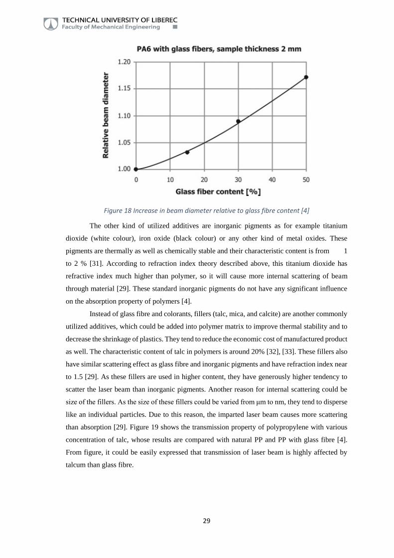
In current construction applications, glass fibres are one of the most used reinforcement.
The higher content of glass fibres is preferred due to the asked final mechanical properties of
product. They are most often combined with PP and PA matrix and their typical content is from
10 to 30 %. According to introduced theory, higher content of glass fibre evoke decrease in the
laser weldability (laser beam intensity on the interface). However in some studies [4], [30], it was
explored that it is possible to weld material even with 30 % content of glass fibres. From figure
18, it could be discerned that the beam relative diameter or laser beam spot size is increasing with
incrementing the glass fibre content.
29
Figure 18 Increase in beam diameter relative to glass fibre content [4]
The other kind of utilized additives are inorganic pigments as for example titanium
dioxide (white colour), iron oxide (black colour) or any other kind of metal oxides. These
pigments are thermally as well as chemically stable and their characteristic content is from 1
to 2 % [31]. According to refraction index theory described above, this titanium dioxide has
refractive index much higher than polymer, so it will cause more internal scattering of beam
through material [29]. These standard inorganic pigments do not have any significant influence
on the absorption property of polymers [4].
Instead of glass fibre and colorants, fillers (talc, mica, and calcite) are another commonly
utilized additives, which could be added into polymer matrix to improve thermal stability and to
decrease the shrinkage of plastics. They tend to reduce the economic cost of manufactured product
as well. The characteristic content of talc in polymers is around 20% [32], [33]. These fillers also
have similar scattering effect as glass fibre and inorganic pigments and have refraction index near
to 1.5 [29]. As these fillers are used in higher content, they have generously higher tendency to
scatter the laser beam than inorganic pigments. Another reason for internal scattering could be
size of the fillers. As the size of these fillers could be varied from μm to nm, they tend to disperse
like an individual particles. Due to this reason, the imparted laser beam causes more scattering
than absorption [29]. Figure 19 shows the transmission property of polypropylene with various
concentration of talc, whose results are compared with natural PP and PP with glass fibre [4].
From figure, it could be easily expressed that transmission of laser beam is highly affected by
talcum than glass fibre.

30
Figure 19 Transmission of PP with talk and glass fibre [4]
As it was introduced, the scattering effect is increased due to higher content of these
additives. But it is necessary to mention that inorganic pigments and fillers also have a significant
effect to the creation of morphology (heterogeneous nucleation) of semi-crystalline materials,
which also influences the losing of beam intensity.
The loss of beam intensity by beam scattering could be approached by increasing the laser
power. By increasing the laser power, it is possible to penetrate the beam deeper in the material
with less amount of scattering. But if the beam power is increased an extravagant amount, the
more heat will be generated at the surface of parts. This could lead to material damage and
degradation of material [4].
2.6. Additives to improve absorption
As already stated, for transmission laser welding, some content of absorbers should be applied to
the absorptive part of the joint geometry, to enhance the absorption property. These absorptive
additives could be carbon black, special kind of inorganic pigments and organic dyes. All of these
additives have certain absorption characteristics at some pre-defined wavelength spectrum, which
are described below:
2.6.1. Carbon black
As a name proposes, carbon black is mainly compounded of carbon particles. Carbon black is
produced by incomplete combustion of hydrocarbons like oil or gases. This conception of
incomplete combustion was taken from the production of “soot”, which is produced in similar
way as carbon black [4], [34].

31
The structure of carbon black is distinguished between particles, aggregates and
agglomerates. Essential particles are individual particles, which has spherical shape and has
diameter from 10 nm to 60 nm. Now, when these individual particles connect each-other by
cohesion bond, they turn into aggregate. These aggregates are then loosely packed up-to
dimensions of 0.3 μm or more, they are known as agglomerates. Figure 20 demonstrates the
complete anatomy of carbon black, how it looks under scanning electron microscopy. The actual
construction of carbon black is more perplexed than this [4], [34]. Carbon black is generally
utilized in rubber and plastic manufacturing industries as a reinforcing agent. It could be used in
tires, inner-liners, tire treads, and food packaging etc [35].
Figure 20 Carbon black anatomy [36]
Carbon black is the most prevalent type of additive utilized for enhancing the absorptivity
of polymers. Generally, any other types of additives typically works under only specified
wavelength spectrum, but only carbon black has a propensity to operate in entire wavelength
spectrum (from UV to NIR) [1], [4]. Figure 21 indicates absorption spectrum of carbon black
under different wavelengths. As carbon black has quite good absorption characteristics, it must
be applied in some range like from 0.01 to 3% [4].
Figure 21 Absorption property of carbon black [4]

32
As the percentage of carbon black increases into the polymer matrix, optical penetration
depth tends to diminish. This optical penetration depth into polymer is limited to some amount
like from 10 μm to 100 μm and it additionally relies on the used wavelength. Figure 22 delineates
the result of various percentage of carbon black to its optical penetration depth for polypropylene
at wavelength of 940 nm [4].
Figure 22 Optical penetration depth vs. various carbon black concentration [4]
As the carbon black is quite economical to produce and it could work in the entire
wavelength range, it is the most prevalent additive to be utilized in all kind of industries. However,
if carbon black is applied on the absorptive part, it tends to transmute its colour to black.
Therefore, there could be an aesthetic problem with carbon black [2], [4]. In integration to this,
carbon black could affect the electrical conductivity of the material, which could be significant
issue for electrical components to be welded [4].
It is still possible to weld two opaque components though. Carbon black has excellent
efficiency towards infrared absorbing capacity so, one of the part should be doped with carbon
black to make it dark. It is impractical to dope transmission part of the joint with carbon black
because the transmission part must be able to transmit laser beam. For solving this problem, it
should be dyed with other suitable dark pigments (red, green). These dyes will still be able to
transmit the laser beam. This solution is mostly applied for gear sensor housing for
automobiles [37].

33
2.6.2. Inorganic pigments
As it was introduced above, the absorption property of materials doped with common inorganic
pigments (as well as fillers) are not significantly increased. Therefore some special types of
additives are necessary to add to increase the absorption properties of absorptive part. The
example of the most used additives of these types are Lazerflair®, Fabulase® and Nano-Indium
Tin Oxide (ITO) [4].
Lazerflair® pigment has a platelet kind of structure, whose diameter is about 15 μm or
less (figure 23). It has multi-layered structure with a core of glimmer, which is coated on both
sides by metal oxides (TiO2 and SnO2). These multi-layered Lazerflair® pigments have wide
range of absorption spectrum i.e. from 900 nm to 2200 nm [4].
Figure 23 Lazerflair® structure [4]
The concentration of Lazerflair® in the absorbing material should be according to
radiated wavelength and it should be in the range of 0.5 – 2% [4]. Lazerflair® pigment does have
some internal scattering due to its particle size, even if it is added in some small concentration. If
the concentration is high, then it could cause more internal scattering, which results in increased
beam diameter. Figure 24 shows the usage of Lazerflair® 825 on Polypropylene material with
thickness of 1.5 mm [4].

34
Figure 24 Transmission of Lazerflair® relative to wavelength [4]
Another type of inorganic additive contains copper phosphate, named Fabulase® 322. It
tends to have good absorption property under some defined wavelength
spectrum (900 to 1500 nm). For Fabulase® 322 to be visible on material under these wavelength,
generally slight green colour is added to the resin. The ratio of this added coloration depends on
the utilized concentration of Fabulase® 322, which is typically from 0.5 to 2%. Fabulase® 322
are mostly available in pigment size of 0.8 μm to 3 μm. Resembling Lazerflair®, Fabulase® 322
also does some internal scattering and engenders haze to the laser beam [4]. Even though,
Fabulase® 322 has better absorption characteristics than Lazerflair® (figure 25).
Figure 25 Fabulase® 322 on PP of thickness 2mm [4]

35
Indium Tin Oxide (ITO) particles are quite small (nanometres) in size and they should be
used only in small concentration, unlikely to Fabulase® 322 and Lazerflair®. Generally, Nano-
ITO has good absorption characteristics in the defined wavelength range from 1000 to 2000 nm
(figure 26). As these particles are very small in size (even smaller than the applied wavelength),
they usually disperses finely into the resin. Due to this reason, the imparted laser beam does not
tend to create a haze [4]. But if the concentration of ITO is increased in material, the resin colour
will turn into slight bluish colour with some hazing effect.
Figure 26 Nano-ITO on PMMA with thickness of 2 mm [4]
2.6.3. Special organic dyes
Special kind of organic dyes such as azo, perionon and perylene are utilized as colorant for
plastics, however they do not have any impact on the absorption property of resin. These dyes
have disadvantage of being chemically and thermally reactive so, they could not be used for high
temperature application of polymers. Adding to this, above introduced organic dyes does not have
any absorption characteristics in the NIR wavelength spectrum [4].
In spite of these all, there do exist some of the exceptions like, Clearweld® and
Lumogen® dyes. These dyes at least have some absorption peak at particular wavelength or
narrow band absorption range in NIR wavelength [1], [4]. Generally, these dyes are subsidiary
for transparent thermoplastics like, PMMA and PC. These dyes should be used according to
weight percentage 0.001% to 0.2% [4].
These organic dyes are only applied for some particular wavelengths like, Lumogen®
IR788 and Clearweld® LWA 208 for 808nm diode lasers or Clearweld® LWA 267 for 940nm
diode lasers (figure 27) [4].

36
Figure 27 Application of Clearweld® dye on PC [4]
To put all these in a nut-shell, for laser welding of thermoplastics, all the conditions like,
used wavelength, material compatibility, demands of coloration, and economic condition, must
be satisfied. Usage of absorbing additives should be according to irradiated wavelength. All of
these are summarized in the table 3 [4].
Table 3 Absorbing additives according to suitable wavelength and materials [4]
Additive Particle
size
(μm)
Absorption
range (nm)
Thermal
stability
Chemical
stability
Visible
influence
Can be used in
Inorganic
pigments
<0.3 Entire
spectrum
500 Excellent Black
coloration
All
thermoplastics
Fabulase
322
<5 900-1600 500 Excellent Slight green
coloration
with
influence to
hue
PE, PP, PA
Lazerflair
825
<5 >1000 500 Excellent Slight green
coloration
with
influence to
hue
PE, PP, PA
ITO <5 >1000 500 Excellent Transparent
colourless
PMMA, PA

37
Additive Particle
size
(μm)
Absorption
range (nm)
Thermal
stability
Chemical
stability
Visible
influence
Can be used in
Clearweld
A267
- 850-1000 <300 Good Slight
transparent
green
coloration
PE, PP, PA
2.7. Joint geometry design
For achieving excellent quality of plastic parts using transmission laser welding, three parameters
should be taken into account: technical parameters, types of additives (absorber in absorptive part)
and joint interface design. Technical parameters (wavelength) and types of absorbers were
described above [4]. The remaining term, design of joint interface will be discussed in this
chapter. For transmission laser welding, the process demands for making successful weld joints
in terms of joint designs are as follows:
Laser transparent and absorbing parts must be placed in an appropriate manner and should
be centred properly;
Joint interface should be parallel and tight enough to each-other, which could be achieved
by some clamping devices;
The concentrated laser beam should irradiate the joint interface as vertical as possible;
Surface roughness of both parts should be low i.e. geometric tolerance should be as low as
possible. Lower surface roughness results in flat surface and this induces close contact
between parts. These close contact between the parts should be provided due to the fact that
proper heat conduction between them only takes place when they are in intimate contact;
For strength criteria, the weld bead size should be equal to nominal wall thickness for unfilled
material. For filled materials, it should be 1.25 times higher than wall thickness;
As for having successful weld joint, intimate contact between the parts is necessary. So the
parts should have minimal warpage. It is not recommended to have a ejector pin marks, gate
or vent location at the weld joint geometry.
Transparent upper part thickness criteria: In addition, sometimes the minimal thickness
criteria should also be taken into consideration. This criteria says that there should be a
minimum thickness of the material between laser source and absorbing part. It is because if
the part is semi-crystalline and if it is highly filled with some fibres or fillers, the beam tends
to scatter more. If the thickness is higher, than the beam could not be able to reach the
interface. Therefore, the transmission part thickness should be maximally 2.5 mm for filled

38
material. For unfilled material, the thickness depends on the transmission rate of that material
[38]. Table 4 shows the relation between thickness and transmission ratio for various
thermoplastics. As PMMA is amorphous plastic, the transmissibility of it is not affected in a
wide range. But for semi-crystalline plastics (PP, PE, PA), the thickness affects more
compared to amorphous [23].
Table 4 Transmission of thermoplastics dependent on thickness
Type of polymer Transmission at thickness =
1 mm
Transmission at thickness
= 10 mm
PMMA 98.8% 88.7%
PA 85.3% 20.4%
PE 80.9% 12.1%
PP 77.1% 7.4%
Beam accessibility: In spite of material thickness, beam accessibility also affects the laser
welding process and should be taken into consideration. According to this criteria, the
components and clamping tools should be designed to allow sufficient access of the laser
beam at weld interface (figure 28). If any of the obstructions (side walls or clamp tools) come
in the way of laser beam, they could cause blockage of the beam thoroughly. For countering
this problem, the beam accessibility should be measured. For successfully counting beam
accessibility, three quantities are required: weld seam width; positional tolerance and
dimensional tolerance. Positional tolerance stands for the allowed movement of the part
during welding and clamping. Whereas, dimensional tolerance is the measurement of size
difference of part before and after welding. Another important parameter is beam cone angle.
It should be perpendicular (90˚ ± 15˚) to the surface of part [39].

39
Figure 28 Beam accessibility and melt collapse
Melt collapse: Melt collapse is also known as melt travel distance or joint path. It is the
distance the two components move along, when they are melted and pressed together by
some clamping forces (figure 28). An ideal range of melt collapse for any material is between
0.1mm to 0.5mm [39]. It could be easily said that melt collapse is dependent on the heat
generated at weld interface, time period of heat application and the clamping pressure. It is
necessary to balance out all of these three quantities to make a better weld. For example, if
the component is taking too much time to make a melt collapse, there could a possibility of
component burning and material degradation. For solving out this problem, increase in
clamping pressure would give the result in allotted time period [39].
By taking all of these criteria into notice, the possible optimal designs could be as mentioned in
figure 29. The joint geometry with square surroundings in figure 29 represents the usage of
welding with two distinct wavelengths. Two laser beam absorbing parts are placed upon each
other. The wavelength should be selected in such a way that, it will surpass through one absorbing
part and absorbed by other [38].
Figure 29 Possible joint designs for transmission laser welding [38]

40
3. Practical part
The main theme of this experiment was to improvise the weldability of thermoplastic parts of
different thicknesses with different concentration of additives (glass fibre and carbon black) using
different process parameters (laser power, scanning speed). The samples were produced by
common injection moulding process. For joining materials, transmission laser welding
technology was utilized. Additionally, for testing these welded samples, tensile test was
performed on them.
3.1. Used laser welding machine:
The laser welding station LM05/05 X.W (figure 30) was designed by VÚTS, a.s. and operates on
a solid state laser with laser source of Yb:Fibre, which had laser class of 4. The machine was
equipped with power supply of 3AC 400V + PE + N and used wavelength was 1064 nm for each
experiments. The maximum power generated by machine was 35 W. The laser machine was
working on NC programing software.
Figure 30 Laser station LM 05/05X.W
From inside, the laser machine has working table, clamping unit and exhaust for
extracting out the fumes generated by laser welding (figure 31).

41
Figure 31 Laser machine configuration
The machine was consisting of “Cross-table” construction for placing work piece (figure
32). The technical data of cross-table is mentioned below:
Working strokes: X axis: 500 mm; Y axis: 500 mm; Z axis: 200 mm;
Positioning accuracy: ±30 μm;
Accuracy of repetition: ±15 μm;
Maximum feed rate: 20 m/min;
Acceleration: 3 m/s2;
Maximum table load: 15 kg;
Table length: 1900 mm;
Table depth 1200 mm;

42
Figure 32 Cross table construction
3.1.1. Control unit
Sinumeric 840D (graphical user interface) is CNC control system for machine tools. By this
control system, it is possible to control the laser power and speed. Using this interface, it is
possible to do interpolation up-to 3 axis. Sinumeric 840D allows the production of small to large
series of work piece. It is also equipped with geometric processor for entering any contours or
shape for laser welding. The basic view of Sinumeric 840D control panel is shown in figure 33.
Figure 33 Control panel OP 010C for Sinumeric 840D

43
3.1.2. Clamping unit
In most of the welding processes, it is certain to have a clamping unit to make sure that there is
no air gap between the parts and the parts remain in intimate contact, which aids in perfect welding
process. It either could be hydraulic, pneumatic or manual. In our case, the clamping was done
manually. As it is visible from figure 34, the clamping unit was consisting of clamp plate, table
and bolts.
Figure 34 Clamping unit (a)
The transparent and absorption parts were placed in-between the table and clamping plate.
This geometry was tightened by two bolts using Hex keys or Allen keys (figure 35). The whole
clamping unit is more clearly visible in figure 35.
Figure 35 Clamping unit (b)

44
3.2. Test specimen production
3.2.1. Material specification
For performing experiment, three different kind of polypropylenes were used. The name of the
first supplier group is Sabic CX03 81 and it is a homo-polymer. This Sabic CX03 81 is highly
crystalline in nature and it is commercially applicable in the field of automotive [1]. Material
datasheet for polypropylene with grade Sabic CX03 81 is mentioned in table 5.
Table 5 Technical datasheet of PP Sabic CX03 81[1]
Properties Value Test standard
Melt flow index MFI 10 g/10 min ISO 1133
Melt flow temperature 230 ˚C -
Yield stress 23 MPa ISO 527-1/2
Stress at break 21 MPa ISO 527-1/2
Strain at break >50% ISO 527-1/2
Density 905 kg/m3 ISO 1183
The second supplier group is Braskem Developmental DH742.01 which is also a homo-
polymer. This polypropylene resin has a very good balance of physical properties. Moreover, this
material was designed for easy processing, low cycle time and good dimensional stability. The
material datasheet is mentioned in the table 6 below.
Table 6 Technical datasheet of PP Braskem DH742.01
Properties Value Test standard
Melt flow index MFI 12 g/10 min ISO 1133
Density 900 kg/m3 ISO 1183
Flexural modulus 1700 MPa ISO 178
The third material used for experiment was Scolefin® 53 G 10-0. It is homo-
polypropylene filled with 30% glass fibre (GF). The main idea of using this material was to
examine the effect of glass fibre on the laser welding operation. The material datasheet of
Scolefin® 53 G 10-0 is mentioned in the table 7.

45
Table 7 Technical datasheet of PP Scolefin® 53 G 10-0
Properties Value Test standard
Melt flow index MFI 15 g/10 min ISO 1133
Yield stress 90 MPa ISO 527-1/-2
Tensile modulus 6800 MPa ISO 527
Tensile strength 90 MPa ISO 527
Density 1120 kg/m3 ISO 1183
For investigating the influence of concentration of glass fibre on laser weldability and on
tensile test, the materials Braskem Developmental DH742.01 and Scolefin® 53 G 10-0 were
mixed. As the goal of this thesis is about improvising the weldability, the additive carbon black
was added in some proportion to the absorption material as well.
3.2.2. Test specimens
All the test samples were produced by injection moulding technology. The produced size of the
specimens was 360 * 150 mm (figure 36). These specimens were further cut manually by hand-
cutter and after that, the required test specimen size was kept to 40 * 40 mm (figure 37) for all the
samples.
Figure 36 Actual specimen from machine

46
Figure 37 Required dimensions after cutting with variant thickness
3.2.3. Injection process
As mentioned above, every test specimens were produced by injection moulding technology using
machine ENGEL VC 1800/300. For the material Sabic CX03 81 with and without carbon black,
following process parameters were being set in the machine for production of samples (table 8).
Table 8 Process parameters for Sabic CX03 81
Property Value
Melt temperature 230 °C
Injection speed 25 mm/s
Holding pressure time 10 s
Cycle time 30 s
Back pressure 10 bar
Clamping force 400 kN
The following table 9 shows the preliminary operation done for producing the samples
and table 10 illustrates the used process parameters for the production of samples from material
Braskem Developmental DH742.01 and Scolefin® 53 G 10-0 with carbon black and glass fibre.

47
Table 9 Preliminary operation done on Braskem Developmental DH742.01 and Scolefin® 53 G 10-0
Property Value
Drying time 3 hours
Drying temperature 90 °C
Table 10 Process parameters for Braskem Developmental DH742.01 and Scolefin® 53 G 10-0
Property Value
Melt temperature 250 °C
Injection time 2.4 s
Injection pressure 180 bar
Injection speed 65 mm/s
Back pressure 5 bar
Holding pressure 120-130 bar
Holding pressure time 8 s
Cooling time 35 s
Back pressure 10 bar
Clamping force 3000 kN
3.2.4. Sample combinations for experiment
During first trial of an experiment, both the parts were of similar grades (Sabic CX03 81). Their
combinations were possible by several ways: sample thickness, amount of carbon black, laser
power and laser scanning speed. So to begin with, the samples were combined with each other by
different thickness. Main aim for performing this experiment was to make sure that there is no
problem in the clamping while using such high thicknesses. In the figure 38 below, it is possible
to see the various combinations made for performing an experiment. One attempted combination
was with transparent and absorption part thickness 3 mm, which was quite high.

48
Figure 38 Combination of samples for specimens with Sabic CX03 81
As per theory, it is also important to dope absorption part with some amount of absorbers
(carbon black) for enhancing weldability, which literally means that it is not possible to weld
samples without doping carbon black on the absorptive part. Even though for proving the theory,
experiments were done without carbon black on absorption part. The results of all of the
mentioned conditions are described in the next chapter of evaluation.
For next experimentation, the chosen materials were Braskem Developmental DH742.01
and Scolefin® 53 G 10-0. In this case, the absorption part was blended with different amounts of
carbon black (1% and 2%) and also with glass fibre, as the idea was to investigate the effect of
glass fibre on the weldability and achieving good weld quality.Taking the results of the previous
experiment into consideration, the amount of thicknesses were changed for achieving better result.
Samples combinations for 1% carbon black with 0%, 10% and 30% of glass fibre could be seen
from the figure 39. In this category, the first experiment was done only with 1% carbon black
(CB) and without any glass fibre (GF) in an absorption part. This experiment was followed by
1% CB with 10% GF and 1% CB with 30% GF respectively.
SA
BIC
PP
with
CB
0%
, 1
% a
nd
2%
in
ab
so
rptio
n p
art Transparent part 2 mm Absorption part 2 mm
Transparent part 3 mm
Absorption part 2 mm
Absorption part 3 mm

49
Figure 39 Combination of samples for second experiment
The above mentioned or similar kind of hierarchy applied for the specimens’ combinations with
carbon black 2% figure 40.
Figure 40 Combination of samples for third experiment
PP
with
CB
1%
with
0%
GF, 1
0%
GF
an
d 3
0%
GF
in
ab
so
rptio
n p
art
Transparent part 1 mm
Absorption part 1 mm
Absorption part 1.5 mm
Absorption part 2 mm
Transparent part 2 mm
Absorption part 1 mm
Absorption part 1.5 mm
PP
with
CB
2%
with
0%
GF, 1
0%
GF
an
d
30
% G
F in a
bso
rptio
n p
art Transparent part 1 mm
Absorption part 1 mm
Absorption part 1.5 mm
Absorption part 2 mm
Transparent part 2 mm
Absorption part 1 mm
Absorption part 1.5 mm
50
3.3. Welding process
3.3.1. Welding of PP for all the conditions
As mentioned previously, specimens with grade Sabic CX03 81 was only used to check any
problem occurrence. The further discussion about this experiment is done in the preceding chapter
of evaluation.
Now, the mentioned hierarchy in the chart (figure 41) above was started with transparent
and absorption part thickness of 1 mm. In this case, absorption part sample was doped with 1%
and 2% of carbon black. The machine was capable to take total maximum power of 35 W and the
setting in the machine was according to the percentage i.e. 50% of power means 50% of 35 W.
Therefore, the value of power will be written like this in percentage. If the laser power is high or
beam velocity is low, then it could cause burning of the samples. On the contrary, if the laser
power is quite low or beam velocity is high, then it could result in no welding or partial welding
between specimens. Therefore to achieve better welding, it is essential to have good combination
of laser power and beam velocity.
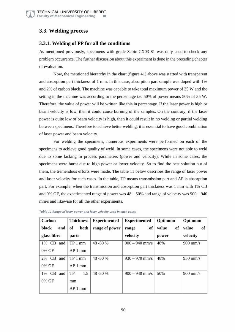
For welding the specimens, numerous experiments were performed on each of the
specimens to achieve good quality of weld. In some cases, the specimens were not able to weld
due to some lacking in process parameters (power and velocity). While in some cases, the
specimens were burnt due to high power or lower velocity. So to find the best solution out of
them, the tremendous efforts were made. The table 11 below describes the range of laser power
and laser velocity for each cases. In the table, TP means transmission part and AP is absorption
part. For example, when the transmission and absorption part thickness was 1 mm with 1% CB
and 0% GF, the experimented range of power was 48 – 50% and range of velocity was 900 – 940
mm/s and likewise for all the other experiments.
Table 11 Range of laser power and laser velocity used in each cases
Carbon
black and
glass fibre
Thickness
of both
parts
Experimented
range of power
Experimented
range of
velocity
Optimum
value of
power
Optimum
value of
velocity
1% CB and
0% GF
TP 1 mm
AP 1 mm
48 -50 % 900 – 940 mm/s 48% 900 mm/s
2% CB and
0% GF
TP 1 mm
AP 1 mm
48 -50 % 930 – 970 mm/s 48% 950 mm/s
1% CB and
0% GF
TP 1.5
mm
AP 1 mm
48 -50 % 900 – 940 mm/s 50% 900 mm/s

51
Carbon
black and
glass fibre
Thickness
of both
parts
Experimented
range of power
Experimented
range of
velocity
Optimum
value of
power
Optimum
value of
velocity
2% CB and
0% GF
TP 1.5
mm
AP 1 mm
48 -50 % 950 – 1000
mm/s
50% 1000 mm/s
1% CB and
0% GF
TP 2 mm
AP 1 mm
48 -50 % 900 – 920 mm/s 53% 920 mm/s
2% CB and
0% GF
TP 2 mm
AP 1 mm
48 -50 % 950 – 1000
mm/s
50% 970 mm/s
1% CB and
0% GF
TP 2 mm
AP 1.5
mm
48 -50 % 900 – 920 mm/s 53% 920 mm/s
2% CB and
0% GF
TP 2 mm
AP 1.5
mm
48 -50 % 900 – 920 mm/s 50% 970 mm/s
1% CB and
10% GF
TP 1 mm
AP 1 mm
48 -50 % 900 – 1000
mm/s
48% 950 mm/s
2% CB and
10% GF
TP 1 mm
AP 1 mm
48 -50 % 900 – 1000
mm/s
48% 950 mm/s
1% CB and
10% GF
TP 1.5
mm
AP 1 mm
48 -50 % 920 – 1000
mm/s
50% 960 mm/s
2% CB and
10% GF
TP 1.5
mm
AP 1 mm
48 -50 % 950 – 1000
mm/s
50% 980 mm/s
1% CB and
10% GF
TP 2 mm
AP 1 mm
50 -53 % 920 – 1000
mm/s
53% 960 mm/s
2% CB and
10% GF
TP 2 mm
AP 1 mm
48 -53 % 950 – 1000
mm/s
50% 950 mm/s
1% CB and
10% GF
TP 2 mm
AP 1.5
mm
53 % 920 – 960 mm/s 53% 960 mm/s
2% CB and
10% GF
TP 2 mm
AP 1.5
mm
50 -53 % 950 – 980 mm/s 50% 960 mm/s

52
Carbon
black and
glass fibre
Thickness
of both
parts
Experimented
range of power
Experimented
range of
velocity
Optimum
value of
power
Optimum
value of
velocity
1% CB and
30% GF
TP 1 mm
AP 1 mm
48 -50 % 900 – 930 mm/s 48% 930 mm/s
2% CB and
30% GF
TP 1 mm
AP 1 mm
48 % 900 – 1000
mm/s
48% 950 mm/s
1% CB and
30% GF
TP 1.5
mm
AP 1 mm
49 % 920 – 960 mm/s 49% 920 mm/s
2% CB and
30% GF
TP 1.5
mm
AP 1 mm
48 -50 % 940 – 980 mm/s 50% 940 mm/s
1% CB and
30% GF
TP 2 mm
AP 1 mm
53 % 920 – 1000
mm/s
53% 940 mm/s
2% CB and
30% GF
TP 2 mm
AP 1 mm
54 % 930 – 980 mm/s 54% 930 mm/s
1% CB and
30% GF
TP 2 mm
AP 1.5
mm
53 % 920 - 940 mm/s 53% 940 mm/s
2% CB and
30% GF
TP 2 mm
AP 1.5
mm
54 % 930 – 980 mm/s 54% 930 mm/s
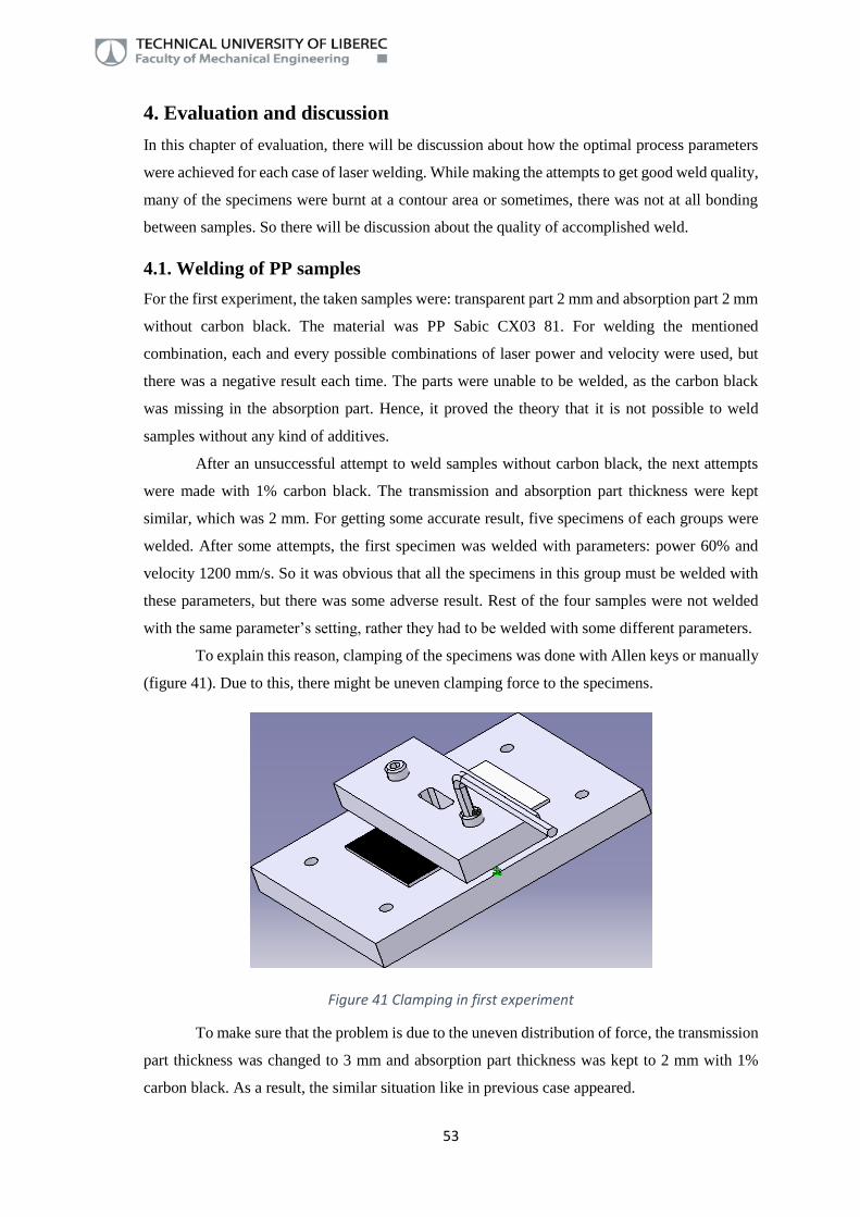
53
4. Evaluation and discussion
In this chapter of evaluation, there will be discussion about how the optimal process parameters
were achieved for each case of laser welding. While making the attempts to get good weld quality,
many of the specimens were burnt at a contour area or sometimes, there was not at all bonding
between samples. So there will be discussion about the quality of accomplished weld.
4.1. Welding of PP samples
For the first experiment, the taken samples were: transparent part 2 mm and absorption part 2 mm
without carbon black. The material was PP Sabic CX03 81. For welding the mentioned
combination, each and every possible combinations of laser power and velocity were used, but
there was a negative result each time. The parts were unable to be welded, as the carbon black
was missing in the absorption part. Hence, it proved the theory that it is not possible to weld
samples without any kind of additives.
After an unsuccessful attempt to weld samples without carbon black, the next attempts
were made with 1% carbon black. The transmission and absorption part thickness were kept
similar, which was 2 mm. For getting some accurate result, five specimens of each groups were
welded. After some attempts, the first specimen was welded with parameters: power 60% and
velocity 1200 mm/s. So it was obvious that all the specimens in this group must be welded with
these parameters, but there was some adverse result. Rest of the four samples were not welded
with the same parameter’s setting, rather they had to be welded with some different parameters.
To explain this reason, clamping of the specimens was done with Allen keys or manually
(figure 41). Due to this, there might be uneven clamping force to the specimens.
Figure 41 Clamping in first experiment
To make sure that the problem is due to the uneven distribution of force, the transmission
part thickness was changed to 3 mm and absorption part thickness was kept to 2 mm with 1%
carbon black. As a result, the similar situation like in previous case appeared.

54
So after performing these experiments, it was sure that there is some problem in the
clamping unit and it needed to be solved. So as a solution of this problem, torque wrench was
used for clamping the specimens. One more problem might be the thickness of specimens. The
combined thickness of them was very high that it was a bit difficult to mount them. So as a
solution, the specimens with lower thicknesses were injected with grades Braskem
Developmental DH742.01 and Scolefin® 53 G 10-0. Moreover, the recent trend in automotive
industry is to make automotive parts as light as possible so that the overall weight of the car
reduces and it eventually results in lower fuel consumption and lower CO2 emission. Below all
the experiments are done with optimized clamping (torque wrench).
4.2. Welding of PP without glass fibre with optimized clamping
For the first evaluation with optimized clamping, absorption part was doped with 1% of carbon
black and 0% of glass fibre. Both transmission and absorption parts were of 1 mm thickness. For
welding, the first trial was made with the combination: laser power 48% and beam velocity 940
mm/s, which resulted in improper welding or there was no welding at all between parts (figure
42).
Figure 42 No welding between specimens
So after it, the beam velocity was reduced to 920 mm/s. This time, the part were welded
but only partially. After that, the laser power was increased to 50% and beam velocity was again
reduced to 900 mm/s. For this case, the welded area was burnt to about 40% (figure 43).

55
Figure 43 Burning of contour area
After three consecutive failures, one more attempt was made with laser power 48% and
beam velocity 900 mm/s. For these parameters, there was observed some satisfactory result of
welding (figure 44).
Figure 44 Perfect welding
Therefore all the specimens were welded with 48% of power and with the velocity of 900
mm/s (table 12). Now, it is obvious that for the similar thicknesses, if the amount of carbon black
is increased in the absorption part, then either the laser power should be decreased or velocity
should be increased. It is because, if the amount of carbon black is more, the specimen tends to
absorb more energy and convert it into melt. The same thing was happened in the following case.
56
When the concentration of carbon black was increased to 2% for same thicknesses, optimal laser
velocity was increased from 900 mm/s to 950 mm/s (table 12). The performed trials in this case
are mentioned in the table 12.
When the transmission part thickness increases, it causes more distraction of laser beam
into material. As a result, the beam tends to reduce its intensity on its way towards absorption
part. So it is obvious to either increase the laser power or decrease the beam velocity. When the
transmission part thickness was increased to 1.5 mm, the optimal process parameters were 50%
laser power and 900 mm/s beam velocity. So compared to TP thickness of 1 mm, laser power was
increased by 2%. When the similar thicker specimens with 2% carbon black were evaluated, beam
velocity was increased by 100 mm/s, as the carbon black helps to absorb the energy. The most
favourable process parameters were: laser power 50% and beam velocity 1000 mm/s (table 12).
When the thickness of transmission part was changed to 2 mm for CB 1% and 2%, the
similar theory of beam distraction applies here also. So for compensating it, the laser power was
increased from 50% to 53% (for CB 1%) for the velocity of 940 mm/s. Now when the amount of
carbon black was increased to 2%, the value of laser power was decreased and beam velocity was
increased. The most appropriate process parameters were: laser power 50% and beam velocity
970 mm/s.
As a last experiment in this group, the absorption part thickness was changed to 1.5 mm,
whereas, the thickness of transmission part was still 2 mm, the same as previous experiment. So
the laser power and beam velocity should be similar because, there is no change in the
transmission part thickness. So the laser beam should not be affected by absorption part thickness
and should be independent to it. Similar kind of theory applies for specimens with
CB 2% (table 12).
In the tables below: N1 means, for the utilized power and velocity setting, specimens
were not welded at all. N2 means the specimens were welded at some extent than N1, but for used
parameters setting, they were welded partially. It means that the specimens were separated
manually.
B1 and B2 tells about the amount of the weld burning area. For used power and velocity,
if the burning marks on contour area are between 50 – 80 %, then it is mentioned with B1. When
the burning marks were lesser than B1 (around 30%), hence not acceptable, it is mentioned with
B2.

57
Ve
loc
ity o
f la
se
r
Pa
rt
Th
ick
ne
ss
Ca
rbo
n
bla
ck
Gla
ss
fib
re
900
920
940
960
980
1000
Po
we
r
Tra
nsm
issio
n
1
- -
829.4
9
N2
N1
48%
Ab
sorp
tion
1
1%
-
B1
50%
53%
Tra
nsm
issio
n
1.5
-
- N
2
48%
Ab
so
rptio
n
1
1%
-
93
2.5
4
N1
50%
B1
53%
Tra
nsm
issio
n
2
- -
48%
Ab
sorp
tion
1
1%
-
50%
B1
B2
946
.62
N1
53%
Tra
nsm
issio
n
2
- -
48%
Ab
sorp
tion
1.5
1%
-
N2
50%
B
1
112
5.6
9
N1
53%
Pa
rt
Th
ick
ne
ss
Ca
rbo
n
bla
ck
Gla
ss
fib
re
900
930
950
970
980
1000
Po
we
r
Tra
nsm
issio
n
1
- -
B
2
902
.23
N1
48%
Ab
sorp
tion
1
2%
-
B
1
50%
53%
Tra
nsm
issio
n
1.5
-
-
N1
48%
Ab
sorp
tion
1
2%
-
B1
B2
9
02
.04
50%
53%
Tra
nsm
issio
n
2
- -
48%
Ab
sorp
tion
1
2%
-
N1
100
7.6
2
B2
50%
B1
53%
Tra
nsm
issio
n
2
- -
48%
Ab
sorp
tion
1.5
2%
-
N
1
N2
120
4.2
4
50%
B
1
53%
Table 12 Process parameter adjustment for specimens without glass fibre

58
4.3. Evaluation of PP with 10% glass fibre
In the chapter 4.2, absorption part was only doped with carbon black, but in this part of
experiment, the absorption part was also mixed with 10% of glass fibre. Similar hierarchy of
experiments had been proceeded in every group. So the first experiment was performed on
transmission and absorption part thickness of 1 mm with carbon black 1%. As glass fibre were
present in the absorption part, they could also help in enhancing the weldability. So to prove it,
the first trial was made with power 50% and velocity 920 mm/s, which resulted into full burning
of the welding contour. Then, the power was reduced to 48%, but still there were some burning
marks. After that, the laser velocity was increased to 980 mm/s with 48% power, which gave a
result of partial welding between specimens. Then, as a final trial, laser power of 48% and
velocity of 950 mm/s was implemented. This combination gave the best result of welding (table
13). From table 12, it can be seen that, when the similar thickness were experimented without
glass fibre, the optimal parameters were: laser power 48% and velocity 900 mm/s. While
here, the velocity was 950 mm/s and used power was 48%. So it can be stated that glass fibre
helps in enhancing the process. When the similar combination of thickness was experimented
with carbon black 2%, it was observed that the proper combination of parameters was similar as
parameters with carbon black 1%. The used parameters for welding were: laser power 48% and
velocity 950 mm/s.
Once the first stage is completed, the transmission part thickness was changed to 1.5 mm.
Rest of the things were similar (carbon black 1% and glass fibre 10%). So as the transmission
part thickness was increased, firstly the laser power was increased to 50% and to maintain proper
combination, velocity was also increased to 1000 mm/s. As a result, the parts were not welded.
So to solve this, laser velocity was decreased to 920 mm/s and it gave the result of burning marks.
Again the adjustments were made with laser power of 48% with 920 mm/s velocity but still, the
sample was burnt partially. So the velocity was increased to 960 mm/s with power of 48% and it
gave result of no bonding between samples. Then, the power was increased to 50% and this
combination gave satisfactory result. In a case, when the absorption part was without glass fibre,
applied velocity was 900 mm/s. While in present scenario, the velocity was increased to 960
mm/s. This means that glass fibre helps in reducing the cycle time by increasing the velocity.
When the amount of carbon black was increased to 2%, the weld contour area was burnt by using
48% power and 960 mm/s velocity. So when the velocity was increased to 980 mm/s, again the
contour area was slightly burnt. So afterwards, the laser speed was increased to 1000 mm/s and
power to 50%, which gave a result of no bonding between samples. Then, laser velocity was
reduced to 980 mm/s and there was perfect welding of samples (table 13). If the parameter setting
is compared, it can be seen that for CB 1%, beam velocity was 960 mm/s, while for carbon black
2%, it was 980 mm/s. In both the cases, laser power was similar (50%). So it is possible to say

59
that increase in the amount of carbon black helps in increasing the productivity of welding
process.
Ve
loc
ity o
f la
se
r
Pa
rt
Th
ick
ne
ss
Ca
rbo
n
bla
ck
Gla
ss
fib
re
90
0
920
950
960
98
0
1000
Po
we
r
Tra
nsm
issio
n
1
- -
- B
2
838
.63
- N
1
- 48%
Ab
sorp
tion
1
1%
10%
-
B1
- -
- -
50%
- -
- -
- -
53%
Tra
nsm
issio
n
1.5
-
- -
B2
- N
2
- -
48%
Ab
sorp
tion
1
1%
10%
-
B1
- 9
93
.4
- N
1
50%
-
-
- -
53%
Tra
nsm
issio
n
2
- -
-
-
- -
48%
Ab
sorp
tion
1
1%
10%
-
-
- N
1
- 50%
- B
1
- 1
06
3.4
1
- -
53%
Tra
nsm
issio
n
2
- -
-
-
- -
48%
Ab
sorp
tion
1.5
1%
10%
-
-
-
- 50%
- B
1
- 1
16
0.1
8
- -
53%
Pa
rt
Th
ick
ne
ss
Ca
rbo
n
bla
ck
Gla
ss
fib
re
90
0
930
950
960
98
0
1000
Po
we
r
Tra
nsm
issio
n
1
- -
- B
2
906
.08
- N
1
- 48%
Ab
sorp
tion
1
2%
10%
-
B1
- -
- -
50%
- -
- -
- -
53%
Tra
nsm
issio
n
1.5
-
- -
- -
B1
B2
- 48%
Ab
sorp
tion
1
2%
10%
-
- -
- 9
11
.78
N1
50%
- -
- -
- -
53%
Tra
nsm
issio
n
2
- -
- -
N1
- -
- 48%
Ab
sorp
tion
1
2%
10%
-
- 1
10
2.5
-
N2
- 50%
- -
B1
- -
- 53%
Tra
nsm
issio
n
2
- -
- -
- -
- -
48%
Ab
sorp
tion
1.5
2%
10%
-
- -
120
4.2
4
N1
- 50%
- -
- B
1
- -
53%
Table 13 Process parameter adjustment for specimens with 10% glass fibre

60
For the next experiment, the transmission part was changed to 2 mm where absorption
part thickness was 1 mm with 1% of carbon black. As the thickness was still increased, for the
first attempt, the used combination was: laser power 50% and velocity 980 mm/s. But there was
partial welding of the specimen. The specimen was separated manually. So as a consequence, the
laser power was increased to 53% and velocity was reduced to 920 mm/s, but it imparted some
burn marks on specimen. So for final, the laser velocity was increased to 960 mm/s and laser
power was 53%. This was perfect combination of parameters for this case. When the absorption
part was without glass fibre, the suitable parameters were: power 53% and velocity 940 mm/s,
whereas in the present case, due to glass fibre, the velocity was increased to 960 mm/s. This
increment in velocity shows the improvement in the process due to the presence of glass fibre.
After this, the amount of carbon black was increased to 2%. And for this experiment, the utilized
process parameters were: laser power 50% and laser velocity 950 mm/s (table 13). It can be seen
that, in an experiment with carbon black 2%, there is an increase in the velocity than it was in
experiment with carbon black 1%. So again, this phenomena proves that if the amount of carbon
black is raised, it helps improving the welding process. When the transmission part thickness was
1.5 mm, used velocity was 980 mm/s, whereas here, the velocity was 950 mm/s. So it could be
stated that increase in the transmission part thickness takes more time to weld and thus, it affects
economically.
As a last experiment in this stage, absorption part thickness was increased to 1.5 mm,
while transmission part thickness was unchanged. As there is no change in the transmission part
thickness, the utilized process parameters were similar as in previous case for carbon black 1%
and 2% (table 13). In the case of specimens without glass fibre and with carbon black 1%, laser
velocity was 940 mm/s. When in present scenario, used velocity was 960 mm/s. So due to this
increase in the velocity, it is possible to say that glass fibre helps in lowering the cycle time. If
the parameters for carbon black 1% and 2% are compared, it can be seen that for CB 1%, used
parameters were: laser power 53% and velocity 960 mm/s. While for CB 2%, laser power was
50% and velocity was 960 mm/s. This decrease in the power value is due to glass fibre.
4.4. Evaluation of PP with 30% glass fibre
In the previous case, the absorption part was doped with carbon black and 10% of glass fibre.
Therefore, as a last part of an experiment, absorption part was added with 30% of glass fibre and
of course, with carbon black. According to the presumption, as the concentration of glass fibre
increases, it would result in higher melting of absorption part. Thus, increase in glass fibre content
should aid in weldability for laser welding process. For the first trial, transmission and absorption
part thickness was 1 mm with 1% of carbon black. At the beginning, the process parameters were:
laser power 50% and beam velocity 900 mm/s. As a result, the welding contour area was burnt
more than 50%. So the laser power was reduced to 48% but still, there were some amount of

61
burning marks. Therefore, to avoid these burn marks, laser velocity was increased to 960 mm/s.
But there was no welding between specimens. The, the velocity was changed to 930 mm/s with
48% power. This time, the quality of weld was better. When there was no glass fibre present in
an absorption part, used velocity for welding was 900 mm/s, while in this case, it is 930 mm/s.
So it could be said that glass fibre helps in improving the process parameters. The parameters
were improved because the glass fibre aids in the beam energy separation, which results in easier
melting of the specimen. After that, the amount of carbon black was increased to 2%. In this
case, the first attempt was done with 48% power and 980 mm/s velocity, but it resulted in no
bonding between samples. So the velocity was reduced to 950 mm/s and the specimens were
welded this time (table 14). So when the specimen was doped with 1% of CB, used velocity
was 930 mm/s, whereas with 2% of CB, used velocity was 950 mm/s. These values show that
carbon black helps in improvising the weldability as well as process parameters.
For the next case, transmission part thickness was increased to 1.5 mm. As the thickness
was increased, it was necessary to adjust the process parameters accordingly. For carbon black
1%, the first used parameters were: 53% power and 930 mm/s speed. But the outcome was slight
burning of contour area. So as a next trial, laser power was set to 50% and velocity was 960
mm/s. This time, the result was opposite than previous case. There was no welding occurred
between samples. So the laser velocity was reduced to 930 mm/s and the result was better
compared to last one. When the transmission part thickness was 1 mm, at that time used power
was 48%, while in the present situation, power was 50%. This increase in the power was due to
the increase in the thickness of transmission part. As the amount of carbon black was increased
to 2%, the first used parameter was: laser power 48% and speed 950 mm/s. But the samples were
not welded. Then, the laser power was set to 50% and velocity was kept to 980 mm/s. But this
time, the result was even worse. The samples were easily separated manually. So as a last trial,
the velocity was set to 950 mm/s with 50% power. By this parameter’s setting, the bonding
between specimens was better. When the amount of carbon black was 1%, used laser velocity
was 930 mm/s, but in this case with carbon black 2%, laser velocity was 950 mm/s. This increase
in the velocity shows the effect of carbon black in the specimen. To add up, the effect of increase
in the thickness could be seen from the table 15. When the thickness of transmission part for CB
2% was 1 mm, used laser power was 48% and velocity was 950 mm/s. While for the present case
with 1.5 mm transmission part, used power was 50% with the similar velocity. So this parameter
setting proves that for higher value of thickness, either the power should increase or velocity
should go down.

62
Table 14 Process parameter adjustment for specimen with 30% glass fibre
Ve
loc
ity o
f la
se
r
Pa
rt
Th
ick
ne
ss
Ca
rbo
n
bla
ck
Gla
ss
fib
re
900
930
950
960
980
1000
Po
we
r
Tra
nsm
issio
n
1
- -
B2
105
4.1
6
- N
1
- -
48%
Ab
sorp
tion
1
1%
30%
B
1
- -
- -
- 50%
- -
- -
- -
53%
Tra
nsm
issio
n
1.5
-
- -
- -
- -
- 48%
Ab
sorp
tion
1
1%
30%
-
110
9.6
2
- N
1
- -
50%
- B
1
- -
- -
53%
Tra
nsm
issio
n
2
- -
-
-
- -
48%
Ab
sorp
tion
1
1%
30%
-
- -
-
- 50%
- B
1
110
9.4
4
- N
1
- 53%
Tra
nsm
issio
n
2
- -
- -
- -
- -
48%
Ab
sorp
tion
1.5
1%
30%
-
- -
- -
- 50%
- -
114
7.8
9
- -
- 53%
Pa
rt
Th
ick
ne
ss
Ca
rbo
n
bla
ck
Gla
ss
fib
re
900
930
950
960
980
1000
Po
we
r
Tra
nsm
issio
n
1
- -
- -
574
.36
- N
1
- 48%
Ab
sorp
tion
1
2%
30%
-
- -
- -
- 50%
- -
- -
- -
53%
Tra
nsm
issio
n
1.5
-
- -
- N
1
- -
- 48%
Ab
sorp
tion
1
2%
30%
-
- 7
81
.70
- N
2
- 50%
- -
- -
- -
53%
Tra
nsm
issio
n
2
- -
- -
- -
- -
48%
Ab
sorp
tion
1
2%
30%
-
- -
- -
- 50%
B1
835
- N
1
- -
53%
Tra
nsm
issio
n
2
- -
- -
- -
- -
48%
Absorp
tion
1.5
2%
30%
-
947.8
5
- -
- -
50%
- -
- -
- -
53%

63
For next experiment, the transmission part thickness was increased to 2 mm. For carbon
black content of 1%, the first used parameters were: 53% power and 930 mm/s laser speed. This
resulted in high numbers of burning marks. So the laser velocity was increased to 980 mm/s and
it gave completely opposite result. This time the samples were easily separated manually. So as
a solution, laser velocity was reduced to 950 mm/s. This combination gave some good result and
the specimens were welded perfectly. When the same experiment was made without glass fibre,
used velocity was 940 mm/s. So it could be stated that there is some notable difference in the
process parameters, when the specimens were doped with glass fibre. When the doping of carbon
black was increased to 2%, settled parameters were: laser power 53% and velocity 930 mm/s.
For the last scenario, absorption part thickness was increased from 1 mm to 1.5 mm. As
mentioned in previous experiments, this absorption part thickness has no significant effect on the
laser weldability (table 14). Therefore, the process parameters for CB 1% was similar as they
were for absorption part 1 mm (power 53% and velocity 950 mm/s). Also, the parameters’ setting
for CB 2% was similar as they were for absorption part 1 mm (power 50% and velocity 930
mm/s).
4.5. Evaluation by breaking force
Quality of welding could be assured by many aspects, but the most common are performed by
checking visual and mechanical properties. Discussion about quality of weld by visual means
(burning marks and partial welding) is already done in previous chapter. Therefore in this part,
the mechanical quality of weld joint was made. To check the quality of weld, the evaluation was
done by using tensile testing (TIRAtest 2300). The used standard for carrying out the test was
TL 52018 and used loading rate or strain rate for performing tensile test was 15 mm/min.
When there was no carbon black present in the absorption part, it was not at all possible
to weld the samples because, some kind of additives (glass fibre, carbon black) must be present
in an absorption part to convert the laser beam energy into heat. Therefore, it was vital to dope
absorption part with carbon black and glass fibre.
Therefore, the evaluation process was started with specimen containing only carbon
black (1% and 2%). In Figure 45, there is a detailed information about the breaking force. It is
obvious from figure 45 that when the thickness of transmission part is increased from 1 mm to
1.5 mm and 2 mm, there is no significant difference in the amount of breaking force (due to the
range of standard deviation). It could be because of the process parameters setting. The adjusted
parameters were not the same for all of them. If they were same for each one, there might be a
problem of burning the specimens or partial welding. Also when the value of carbon black was
increased from 1% to 2% for all the cases, there was very slight change in the force. Again the
reason of this phenomena could be different setting of the parameters. But when the absorption
part thickness was increased from 1 mm to 1.5 mm, it could be stated that there is some notable

64
deviation in the value of breaking force then the rest. For an example, when the transmission part
and absorption part were of thickness 2 mm and 1 mm respectively (for CB 1%), value of
breaking force was 946.6 N, whereas it was 1125.7 N for transmission and absorption part 2 mm
and 1.5 mm respectively. Table with detailed information about breaking force and standard
deviation (with concrete values) for each cases is attached in the attachment.
Figure 45 Maximum force for specimens without glass fibre
When the absorption part was mixed with glass fibre alongside with carbon black, mostly
it changed the setting of process parameters (either reduce the power or increase the speed) as
discussed. According to theory, if any specimen is doped with glass fibres, it aids in enhancing
the mechanical strength during tensile test. Moreover, laser beam tends to lose its intensity while
passing through the glass fibre doped material and it eventually helps in creating more heat and
melt at the weld interface. This could result in better weld joint between specimens. Therefore
there was a presumption made that doping of glass fibre in the absorption part alongside with
carbon black might help in increasing the mechanical strength. So when the specimens were
doped with glass fibres, it could be seen from figure 46 that value of breaking force is slightly
raising than the cases without glass fibres. But also it is needless to say from figure 46 that the
values of standard deviation were quite high. As like on previous case (without glass fibre), here
also the increasing thickness of transmission part did not evoke breaking force, i.e. with an
increase in transmission part thickness from 1 mm to 1.5 mm and 2 mm, the value of breaking
force was nearly the same for each of them. When the absorption part thickness was increased
from 1 mm to 1.5 mm, value of breaking force was not increased significantly. Moreover, from
figure 46, it could be seen that when the amount of carbon black is increased from 1% to 2%,
value of breaking force is about the same as for carbon black 1%. The root cause of this
phenomena was used process parameters. They were not the same for each of them. Though this
increase in carbon black changed the process parameters’ setting (either increase in the velocity
550.0
650.0
750.0
850.0
950.0
1050.0
1150.0
1250.0
1/1 1.5/1 2/1 2/1.5
Ave
rage
bre
akin
g fo
rce
(N
)
Thickness combination (mm)
1%CB
2%CB

65
or decrease in power), for getting good quality of weld. These mentioned changes in the process
parameters could help the laser welding process economically.
Figure 46 Maximum force for specimens with 10% glass fibre
When the absorption part was mixed with carbon black and 30% glass fibres, results for
carbon black 1% were quite impressive. In this particular case (CB 1%), the raise in amount of
glass fibre not only altered the setting of process parameters (either reduction in power or
increment in velocity) but also increased the mechanical quality of joint. If the values of breaking
force for transmission and absorption part 1 mm with CB 1% is compared to the case without
and with 10% glass fibre (figure 45, 46, 47), there is some notable difference in them (except the
variants of transmission part 2 mm). This raise in breaking force was due to increased amount of
glass fibre. From figure 47, it is possible to state that the values of breaking force for all the
thickness combinations with 1% of carbon black and 30% of glass fibre are nearly the same. For
variants of transmission part thickness 2 mm (with absorption pat 1 mm and 1.5 mm), used
process parameters were similar for both. But the value of breaking force was nearly similar here,
because of standard deviation. There was a presumption made for variants of carbon black 2%
and glass fibre 30% that, the value of breaking force should be the highest amongst each variants
(without glass fibre, with 10% glass fibre) or at least on a same level with carbon black 1% but,
the outcome for specimens with carbon black 2% was a bit interesting. It was because the value
of average breaking force was the least for all the variants.
550.0
650.0
750.0
850.0
950.0
1050.0
1150.0
1250.0
1/1 1.5/1 2/1 2/1.5
Ave
rage
bre
akin
g fo
rce
(N
)
Thickness combination (mm)
1%CB
2%CB

66
Figure 47 Maximum force for specimens with 30% glass fibre
550.0
650.0
750.0
850.0
950.0
1050.0
1150.0
1250.0
1/1 1.5/1 2/1 2/1.5
Ave
rage
bre
akin
g fo
rce
(N
)
Thickness combination (mm)
1%CB
2%CB

67
5. Conclusion
Laser welding is by far one of the most used and precise non-conventional methods for joining
two thermoplastic products which have a wide range of applications in all the industries. There
are different kinds of lasers (CO2 laser, Nd:YAG laser, Diode laser, Fibre laser) and all of them
can be adopted according to their wavelengths. These different kinds of lasers divide laser
welding technology in two: direct laser welding (CO2 laser) and through-transmission laser
welding (Nd:YAG laser, Fibre laser), from which through-transmission laser welding (TTLW)
is founded most commonly in practice for joining plastic parts.
The main theme of the thesis was to investigate the weldability of polypropylene
homopolymer with respect to sample thickness and chosen kind of additives by laser welding
technology. The specimens were produced by injection moulding technology and their thickness
was kept lower (1 mm, 1.5 mm and 2 mm), in order to fulfil the increasing demands from
companies to achieve as low weight of the part as possible. As an additive of polypropylene,
variants with CB (1% and 2%) as well as with GF (0%, 10%, and 30%) were also examined.
Glass fibre helps in increasing the mechanical strength and also it has a characteristic of high
temperature resistance. Therefore, PP based composites with glass fibre is commonly founded in
a lot of the applications. All of these samples were welded on laser welding station LM05/05
X.W, which was designed by VÚTS, a.s. and equipped with a solid state laser with a laser source
of Yb:Fibre.
By performing the first experiment, it was detected that despite of keeping the same
process parameters, mechanical quality of weld was not similar for each specimen. For example,
by keeping the same parameters, sometimes the specimens were burnt or sometimes they were
partially welded. This problem could be due to the uneven force distribution on the samples
caused by clamping plate and the force distribution problem was increased with higher
specimens’ thickness. Therefore, to negotiate this problem, optimized clamping (torque wrench)
was used to make sure that the force distribution is even and also specimens with lower thickness
were injected.
Theoretical presumption says that, if the transmission part thickness is raised, then
obviously the laser beam must be able to penetrate deep into the material and by doing so, the
beam tends to lose its intensity or energy until it reaches to the absorption part. So to compensate
this effect and to have a good quality of the weld, in the laser machine, either the value of power
should be increased or the rate of velocity should be lowered so that, the laser beam can properly
melt the weld area. A similar thing was witnessed during the experiment. When the transmission
part thickness was increased from 1 mm to 1.5 mm and 2 mm, process parameters were also
altered as mentioned above. However, this change in the process parameters had a very minute
effect on the mechanical weld quality due to the standard deviation factor. On the contrary, when

68
the absorption part thickness was increased (from 1 to 1.5 mm), it was not necessary to change
the parameters because increase in absorption part thickness has no dependency on the process
parameters. While this increase in absorption part thickness helped in elevating mechanical weld
quality (breaking force) by some amount (except for the case GF 30%).
From the performed experiments, it was confirmed that in order to weld plastic parts by
laser technology, doping of carbon black into an absorption part becomes necessary. As the
theory suggests, when the amount of carbon black increases, then the melting procedure of both
the parts at weld area becomes easier due to higher energy generation, which could result in either
reduction in the power or increment in the velocity of the beam. Thence, the exact similar thing
was observed during an experiment. These changes in process parameters however did not evoke
the mechanical quality of weld joint (breaking force), but it could be stated that when the velocity
of laser beam increases, it lessens the time of welding and eventually results in higher
productivity with similar weld quality.
According to the theoretical presumption, as the laser beam penetrates into the polymer
matrix, which is doped with glass fibre, the beam tends to lose its energy and convert it into heat,
which results in easier melting of specimens. Before performing an actual experiment, it was
assumed that increase in heat generation and easier melting of specimens due to glass fibre would
evoke a change in process parameters (either reduce the power or increase the velocity). Even
though for specimens with 10% glass fibre, there was not necessary to change the values of
process parameters (compared to 0% GF) and moreover, there was no marginal difference in
mechanical weld quality. Whereas, when the absorption part was doped with 1% CB and 30%
GF, it was necessary to change the process parameters (compared to 0% GF) to maintain good
weld quality (no burning or partial welding). Additionally, the mechanical weld quality (breaking
force) was also improved by a significant amount. However, for specimens with 2% CB and 30%
GF, there was observed very interesting results than the presumption. The mechanical weld
quality was decreased in this particular case.
To put all these things in a nutshell, it could be concluded that for successful laser
welding between two parts, the absorption part must be doped with some sort of additives (carbon
black, glass fibre). Also, it is better to increase the thickness of an absorption part rather than
increasing transmission part thickness in light of a fact that, if the absorption part thickness
increases, it does not require any adjustment in the process parameters’ setting and in addition, it
also helps in building some good mechanical quality of joint.
Finally, it is noteworthy to mention that these experimental measurements were made
only for one kind of polypropylene. Therefore, the introduced results could not be general. For
general conclusion, it would be necessary to do more experiments on a different kind of
polypropylene (copolymers, polymer blends). Very interesting information could be for example
to know the influence of different kind of additives (colorants, minerals, natural fibres) on

69
weldability. Next recommendation is to find a better solution for optimization of clamping units.
Although there was made an optimization of specimens’ fixation, value of standard deviation for
evaluated results (breaking force) was still high. Therefore next optimization of this process
should be made.
70
6. Reference
[1] Troughton, Michael John. Handbook Of Plastics Joining. 2nd ed. William Andrew Inc.,
2008. Print.
[2] Katayama, S. Handbook Of Laser Welding Technologies. 1st ed. Woodhead Publishing
Limited, 2013. Print.
[3] “Transmission laser welding of plastics (May 2002).” [Online]. Available:
http://www.twi-global.com/technical-knowledge/published-papers/transmission-laser-welding-
of-plastics-may-2002/. [Accessed: 16-Feb-2017].
[4] KLEIN, Rolf. Laser welding of plastics. 1. Weinheim: Wiley-VCH, 2012.
[5] “The growth of laser welding of plastics.” [Online]. Available: http://www.industrial-
lasers.com/articles/print/volume-26/issue-2/features/the-growth-of-laser-welding-of-
plastics.html. [Accessed: 17-Feb-2017].
[6] Csele, Mark. Fundamentals Of Light Sources And Lasers. 1st ed. Hoboken, N.J.: Wiley-
Interscience, 2004. Print.
[7] “What is the difference between a laser and an ordinary wave of light? - Quora.”
[Online]. Available: https://www.quora.com/What-is-the-difference-between-a-laser-and-an-
ordinary-wave-of-light. [Accessed: 02-Apr-2017].
[8] “Principles and Applications of Laser - MSE 5317.” [Online]. Available:
http://electrons.wikidot.com/principle-and-application-of-laser. [Accessed: 29-Dec-2016].
[9] G. Thomas and R. Isaacs, “Basic principles of lasers,” Anaesth. Intensive Care Med.,
vol. 12, no. 12, pp. 574–577, [Accessed: Dec-2011].
[10] Lackner, M., 2008. Lasers in chemistry, Weinheim: Wiley-VCH.
[11] “Encyclopedia of Laser Physics and Technology - lasers, principle of operation,
resonator, cavity, laser beam, stimulated emission.” [Online]. Available: https://www.rp-
photonics.com/lasers.html. [Accessed: 29-Dec-2016].
[12] “Nd:YAG laser - Definition, Construction and Working.” [Online]. Available:
http://www.physics-and-radio-electronics.com/physics/laser/ndyaglaser.html. [Accessed: 12-
Mar-2017].
[13] "CO2 Lasers Vs. Nd:YAG Lasers | Litron". Litron.com. Web. [Accessed: 29-Mar-
2017].
[14] “Nd:YAG Lasers – Properties and Applications,” AZoOptics.com, 09-May-2013.
[Online]. Available: http://www.azooptics.com/Article.aspx?ArticleID=470. [Accessed: 29-
Mar-2017].

71
[15] “Laser Polymer Welding.” [Online]. Available:
https://www.rofin.com/en/applications/laser-welding/laser-welding-of-polymers/. [Accessed:
29-Mar-2017].
[16] “Diode Lasers for Plastic Welding Applications - Novus Light Today.” [Online].
Available: http://www.novuslight.com/diode-lasers-for-plastic-welding-
applications_N2925.html. [Accessed: 29-Mar-2017].
[17] “Welding of plastics and thermoplastics with laser - Laserline USA.” [Online].
Available: http://www.laserline.de/diode-laser-plastic-welding.html. [Accessed: 29-Mar-2017].
[18] “Laser Welding of Plastics - Concepts & Solutions - Dukane.” [Online]. Available:
https://www.dukane.com/us/PLA_Laser.htm. [Accessed: 17-Feb-2017].
[19] “Laser Plastic Welding - Leister Laser Plastic Welding.” [Online]. Available:
https://www.leister.com/en-us/laser-plastic-welding?nr=true. [Accessed: 28-Dec-2016].
[20] "What Is Transmission Welding? | Laser Plastic Welding". Laserplasticwelding.com.
Web. [Accessed: 18-Feb-2017].
[21] "EFFICIENCY OF POLYAMIDES FOR INFRA-RED WELDING". Www8.basf.us. N.p.,
2003. Web. [Accessed: 18-Apr-2017].
[22] "Application Gallery | Laser Plastic Welding". Laserplasticwelding.com. Web.
[Accessed: 18-Feb-2017].
[23] “RELATIONSHIP BETWEEN OPTICAL PROPERTIES AND OPTIMIZED
PROCESSING PARAMETERS FOR THROUGHTRANSMISSION LASER WELDING OF
THERMOPLASTICS". Www8.basf.us. N.p., 2017. Web. [Accessed: 18-Apr-2017].
[24] E. Ghorbel, G. Casalino, and S. Abed, “Laser diode transmission welding of
polypropylene: Geometrical and microstructure characterisation of weld,” Mater. Des., vol. 30,
no. 7, pp. 2745–2751, Aug. 2009.
[25] "Polypropylene Welding | Miller Weldmaster". Weldmaster. Web. [Accessed: 28-
Apr-2017].
[26] “BMW M3 Replica Bumper for Sedan - E46Fanatics.” [Online]. Available:
http://forum.e46fanatics.com/showthread.php?t=489600. [Accessed: 22-Apr-2017].
[27] Shengui C, Singare S. "Laser Transmission Welding Of Polycarbonate: Geometrical And
Microstructure Characterisation Of The Weld". Journal of Material Science &
Engineering 04.04 (2015): n. pag. Web. [Accessed: 24-Apr-2017].
[28] “PlasticsEurope - Polymethyl methacrylate (PMMA) - PlasticsEurope.” [Online].
Available: http://www.plasticseurope.org/what-is-plastic/types-of-plastics-11148/engineering-
plastics/pmma.aspx. [Accessed: 24-Apr-2017].
[29] Rothon, Roger N. Particulate-Filled Polymer Composites. 2nd ed. Shrewsbury, UK:
Rapra Technology, 2003. Print.
72
[30] "Laser Welding Of Plastics And Design For Joints Under High Mechanical
Stress". http://www.treffert.org. Web. [Accessed: 17-Feb-2017].
[31] “Materials: Analyzing Filler Content : Plastics Technology.” [Online]. Available:
http://www.ptonline.com/columns/materials-analyzing-filler-content. [Accessed: 28-Apr-2017].
[32] "Additives & Fillers - Composite Materials". CompositesLab. Web.[Accessed: 28-
Apr-2017].
[33] "CHAPTER 1- Introduction (Fillers)". Polymer-filler.blogspot.com. N.p., 2008.
Web.[Accessed: 29-Apr-2017].
[34] “What Is Carbon Black?” [Online]. Available: http://www.carbonblack.jp/en/cb/.
[Accessed: 15-Mar-2017].
[35] C. Mehay, “Carbon Black use in the plastics industry,” Plastixportal. [Online].
Available: http://www.plastixportal.com/carbon-black-use-in-plastics-industry.html. [Accessed:
29-Apr-2017].
[36] "What Is Carbon Black? – Monolith". Monolithmaterials.com. Web. ]Accessed: 15-
Mar-2017].
[37] “Laser Welding Plastic - How It Works.” [Online]. Available:
http://www.lpkfusa.com/products/laser_plastic_welding/learn_about_laser_plastic_welding/.
[Accessed: 19-Feb-2017].
[38] “Laser welding for plastic components (May 2002).” [Online]. Available:
http://www.twi-global.com/technical-knowledge/published-papers/laser-welding-for-plastic-
components-may-2002/. [Accessed: 21-Apr-2017].
[39] “22. Eng-Review Of Laser Plastic Welding Process-
A.B.Humbe". http://www.impactjournals.us. N.p., 2014. Web. [Accessed: 2-May-2017].

73
List of figures
Figure 1. Coherency of laser light
Figure 2. Spntaneous emission
Figure 3. Stimulated emission
Figure 4. Laser generation device
Figure 5. CO2 laser construction
Figure 6. Nd:YAG laser schematic diagram
Figure 7. Diode laser generation
Figure 8. Fibre laser diagram
Figure 9. Direct laser welding
Figure 10. Laser butt welding by CO2 source
Figure 11. Through transmission laser welding
Figure 12. Application in automotive industry
Figure 13. Laser beam scattering through the part
Figure 14. Transmission property of natural PP
Figure 15. Relation between transmission and thickness of product
Figure 16. Optical properties of polycarbonate with respect to wavelength
Figure 17. Optical properties of PC and PMMA with respect to wavelength
Figure 18. Increase in beam diameter relative to glass fibre content
Figure 19. Transmission of PP with talk and glass fibre
Figure 20. Carbon black anatomy
Figure 21. Absorption property of carbon black
Figure 22. Optical penetration depth vs. various carbon black concentration
Figure 23. Lazerflair® structure
Figure 24. Transmission of Lazerflair® relative to wavelength
Figure 25. Fabulase® 322 on PP of thickness 2mm
Figure 26. Nano-ITO on PMMA with thickness of 2 mm
Figure 27. Application of Clearweld® dye on PC
Figure 28. Beam accessibility and melt collapse
Figure 29. Possible joint designs for transmission laser welding
Figure 30. Laser station LM 05/05X.W
Figure 31. Laser machine configuration

74
Figure 32. Cross table construction
Figure 33. Control panel OP 010C for Sinumeric 840D
Figure 34. Clamping unit (a)
Figure 35. Clamping unit (b)
Figure 36. Actual specimen from machine
Figure 37. Required dimensions after cutting with variant thickness
Figure 38. Combination of samples for first experiment
Figure 39. Combination of samples for second experiment
Figure 40. Combination of samples for third experiment
Figure 41. Clamping in first experiment
Figure 42. No welding between specimens
Figure 43. Burning of contour area
Figure 44. Perfect welding
Figure 45. Maximum force for specimens without glass fibre
Figure 46. Maximum force for specimens with 10% glass fibre
Figure 47. Maximum force for specimens with 30% glass fibre

75
Attachment 1
No. Specimens combination Visual quality of weld
1
Transmission 1 mm and
absorption part 1 mm with
1% CB and without GF
2
Transmission 1.5 mm and
absorption part 1 mm with
1% CB and without GF
3
Transmission 2 mm and
absorption part 1 mm with
1% CB and without GF
4
Transmission 2 mm and
absorption part 1.5 mm with
1% CB and without GF
5
Transmission 1 mm and
absorption part 1 mm with
2% CB and without GF

76
6
Transmission 1.5 mm and
absorption part 1 mm with
2% CB and without GF
7
Transmission 2 mm and
absorption part 1 mm with
2% CB and without GF
8
Transmission 2 mm and
absorption part 1.5 mm with
2% CB and without GF
9
Transmission 1 mm and
absorption part 1 mm with
1% CB and 10% GF
10
Transmission 1.5 mm and
absorption part 1 mm with
1% CB and 10% GF
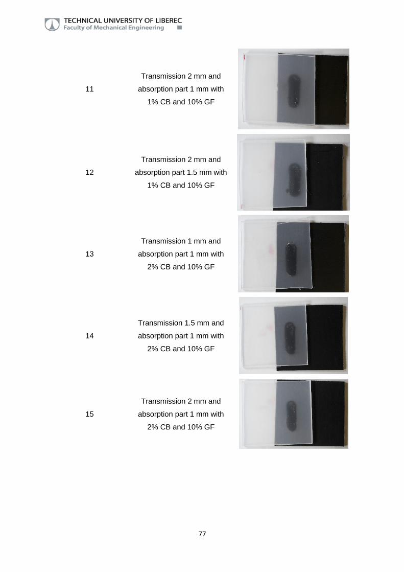
77
11
Transmission 2 mm and
absorption part 1 mm with
1% CB and 10% GF
12
Transmission 2 mm and
absorption part 1.5 mm with
1% CB and 10% GF
13
Transmission 1 mm and
absorption part 1 mm with
2% CB and 10% GF
14
Transmission 1.5 mm and
absorption part 1 mm with
2% CB and 10% GF
15
Transmission 2 mm and
absorption part 1 mm with
2% CB and 10% GF
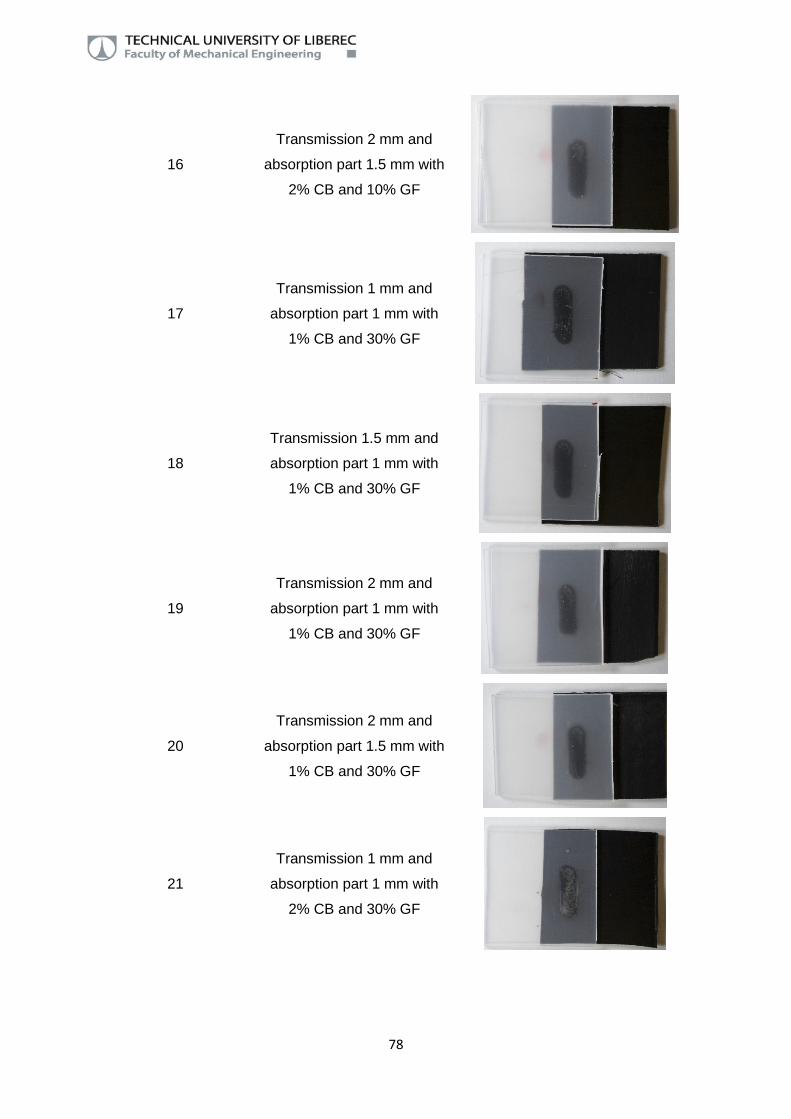
78
16
Transmission 2 mm and
absorption part 1.5 mm with
2% CB and 10% GF
17
Transmission 1 mm and
absorption part 1 mm with
1% CB and 30% GF
18
Transmission 1.5 mm and
absorption part 1 mm with
1% CB and 30% GF
19
Transmission 2 mm and
absorption part 1 mm with
1% CB and 30% GF
20
Transmission 2 mm and
absorption part 1.5 mm with
1% CB and 30% GF
21
Transmission 1 mm and
absorption part 1 mm with
2% CB and 30% GF
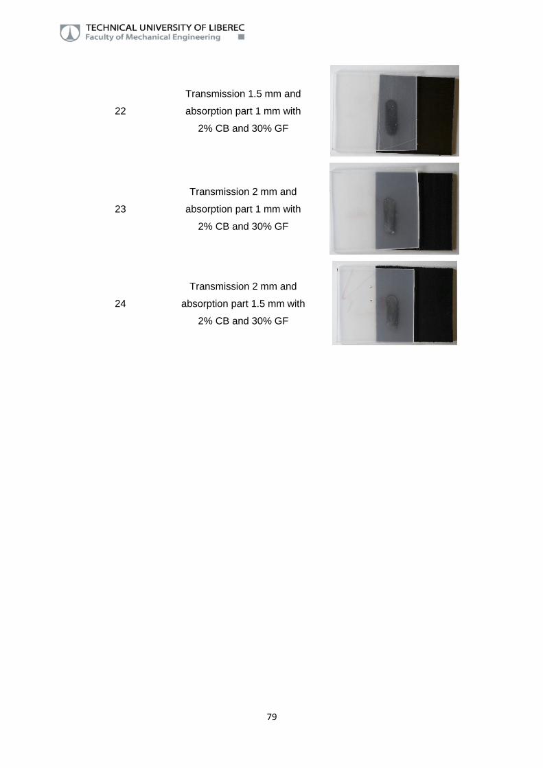
79
22
Transmission 1.5 mm and
absorption part 1 mm with
2% CB and 30% GF
23
Transmission 2 mm and
absorption part 1 mm with
2% CB and 30% GF
24
Transmission 2 mm and
absorption part 1.5 mm with
2% CB and 30% GF

80
Attachment 2
Table 1 Breaking force and standard deviation for all the cases
Glass fibre 0%
Carbon
black Transmission part / Absorption part thickness (mm)
1 / 1 1.5 / 1 2 / 1 2 / 1.5
Breaking
force (N)
Standard
deviation
(N)
Breaking
force (N)
Standard
deviation
(N)
Breaking
force (N)
Standard
deviation
(N)
Breaking
force (N)
Standard
deviation
(N)
1% 829.5 73.6 932.5 101.2 946.6 111.0 1125.7 70.4
2% 902.2 131.7 902.0 77.6 1007.6 77.0 1204.2 88.1
Glass fibre 10%
Carbon
black Transmission part / Absorption part thickness (mm)
1 / 1 1.5 / 1 2 / 1 2 / 1.5
Breaking
force (N)
Standard
deviation
(N)
Breaking
force (N)
Standard
deviation
(N)
Breaking
force (N)
Standard
deviation
(N)
Breaking
force (N)
Standard
deviation
(N)
1% 838.6 59.7 993.4 55.8 1063.4 97.6 1157.2 53.5
2% 906.1 51.8 911.8 75.9 1102.3 79.9 1177.3 56.7
Glass fibre 30%
Carbon
black Transmission part / Absorption part thickness (mm)
1 / 1 1.5 / 1 2 / 1 2 / 1.5
Breaking
force (N)
Standard
deviation
(N)
Breaking
force (N)
Standard
deviation
(N)
Breaking
force (N)
Standard
deviation
(N)
Breaking
force (N)
Standard
deviation
(N)
1% 1054.2 126.2 1109.6 139.9 1109.4 100.5 1147.9 58.9
2% 574.4 117.3 781.7 115.0 835.0 119.3 947.9 77.9

81