study on behaviour of plate girder with plane the web and corrugated web · · 2017-08-23study on...
TRANSCRIPT

Advances in Computational Sciences and Technology ISSN 0973-6107 Volume 10, Number 9 (2017) pp. 2745-2764 © Research India Publications http://www.ripublication.com
Study on the Behaviour of Plate Girder with Plane
Web and Corrugated Web
*R.Rajkumar, **R.Aravindh, ***B.Gokula Krishanan & ****B.Mukul Anand
*Associate Professor, Department of Civil Engineering, SSN College of Engineering, Tamil Nadu, India.
**Undergraduate Student, Department of Civil Engineering,
SSN College of Engineering, Tamil Nadu, India.
***Undergraduate Student, Department of Civil Engineering,
SSN College of Engineering, Tamil Nadu, India.
**** Undergraduate Student, Department of Civil Engineering, SSN College of Engineering, Tamil Nadu, India.
Abstract
The corrugated steel plate is a widely used structural element in many fields of application because of its numerous favourable properties along with being more economical than the conventional rolled sections. In addition, profiling of the web generally avoids failure of the section due to loss of stability before the plastic limit-loading for the web is reached. To increase the shear capacity of web of large steel plate girders, the web with different patterns such as tapered web, haunches, corrugations of different shapes are now being used for different applications. Present paper deals with the study of behaviour of plate girder with the plane web and rectangular corrugated web under different loading conditions. The finite element analysis of the plate girder is carried out using ANSYS software. The results obtained from the analysis are then compared with the plate girder with plane web of uniform depth. It is concluded that the corrugated web plate has high buckling strength and sufficient reduction in weight with light gauge elements, than plate girder with plane web.
Keywords: Corrugated, Steel, Plate, Girder, Structural, Web

2746 R.Rajkumar, R.Aravindh, B.Gokula Krishanan & B.Mukul Anand
1. INTRODUCTION
Plate girder is basically an I- beam built up from plates which are joined together by angles and rivets, with or without stiffeners to obtain the desired size. They are also known as deep flexural members which are capable of carrying heavy loads. Plate girder provides maximum flexibility and economy in design. They offer a unique flexibility in fabrication and the cross section can be uniform or non-uniform along the length. It is possible for providing the exact amount of steel required at each section along the length of the girder by changing the flange areas and keeping the same depth of the girder. In other words, it can be shaped to match the bending moment curve itself. Thus, plate girder offers limitless possibilities to the creativity of the engineer. Usually, the web of the plate girder is subjected to bending, shear or a combination of the two. In construction application, the web usually bears most of the compressive stress and transmits shear in the beam while the flanges support the major external loads. Also, since the plate girders have the maximum moment carrying capacity than any other rolled sections, the section has to be slender. But slender sections are
susceptible to web buckling. This led to the need of slender sections which could be
provided by using corrugations along the web section. The use of corrugations
eventually replaced the use of stiffeners. The main benefit of providing these corrugations is to increase the buckling resistance of the web thereby reducing the thickness of the web and also the overall weight of the section. Furthermore, studies have shown that the use of thinner webs results in lower material cost, with an estimated cost savings of 10-30% in comparison with conventional fabricated sections and more than 30% compared with standard hot rolled universal beams. In our present study, a web with rectangular corrugations is used. The main objective of this project is to determine the buckling strength of corrugated web subjected to shear for different loading conditions. Two plate girders, one with a flat web and another with a corrugated web are designed, analysed and the results are compared. Further the finite element models of plane web as well as corrugated webs are developed and analysis is performed by using ANSYS software.
2. LITERATURE REVIEW
Most of the earlier studies on plate girders with corrugated webs addressed the issues related to rectangular corrugated webs in which the failure of webs may be govern either by shear buckling in the plate parts of the folds or by shear buckling in several folds over a part of girder depth or by shear buckling spread across several folds [1].Perhaps research on corrugated plates dates back to the late sixties when Easley and McFarland [2] studied the buckling of light-gauge corrugated metal shear diaphragms.

Study on the Behaviour of Plate Girder with Plane Web and Corrugated Web 2747
Easley [3] derived, based on the orthotropic plate buckling theory, a set of formulae for buckling loads. Several experimental as well as theoretical investigations on girders with corrugated webs have been carried out since then by a number of researchers. The finite strip method was employed by Luo and Edlund [10] for buckling analysis of corrugated panels. Subsequently, trapezoidally corrugated webs were examined by Luo and Edlund for ultimate strength under patch loading [11] and later for shear capacity. [4] Experimental investigations have been carried out by Elgaaly et al. in order to study the ultimate load behaviour of girders with corrugated webs subjected predominantly to shear loading [5] or to uniform bending [6] or to partial compressive edge loading [7]. Elgaaly and Seshadri [7] employed nonlinear finite element modeling to analyse the girders under different types of loading and, the behaviour up to failure; failure mode and ultimate capacity could be predicted with sufficient accuracy. Y.A. Khalid [9] investigate the bending behaviour of mild steel beams with semicircular web corrugation, determine the effects of corrugated web and the corrugation direction to the beam’s load-carrying capability. Later, Jamali [8] investigated on the torsional properties, that is torsional constant and warping constant that could influence the lateral torsion capacity of trapezoid web profile section. She also performed lateral torsional buckling tests on two beams with normal flat web and two beams with trapezoid web profile.
3. SCOPE AND OBJECTIVES
The scope and objectives of this study are as follows: Study on the behaviour of welded plate girder for variation in geometry of corrugation and thickness of web plate. Preparation and study of the model in ANSYS. Perform the static and buckling analysis. Calculate the buckling strength and weight of corrugated web plate girders. Comparative study of plane web plate girder without stiffeners.
4. NEED FOR CORRUGATIONS
For making the cross section efficient to resist in plane bending it is required that maximum material is placed as far away from neutral axis as possible.As the depth of section increases, depth of web increases and it becomes slender, premature failure of girder due to web buckling in shear might be occur. Hence to reduce the slenderness ratio created by high depth and small thickness of web, instead of using stiffeners, the corrugated web is the possible way to give stability against the elastic buckling of web. Present study deals with rectangular corrugations.

2748 R.Rajkumar, R.Aravindh, B.Gokula Krishanan & B.Mukul Anand
5. OUTLAY OF STUDY
In this dissertation the finite element models of plane web as well as corrugated webs are developed and analysis is performed by using ANSYS software. The results obtained from analysis are then compared with plane web plate girders and corrugated web plate girders.
6. DESIGN
6.1. MANUAL DESIGN OF PLANE WEB PLATE GIRDER
Before analytical work a selected plate girder is first checked as per IS 800-2007. [12]
6.1.1. SECTION SPECIFICATION
Breadth of flange plate bf = 600mm, Thickness of flange plate tf = 40mm, Thickness of web plate tw = 16mm, Depth of web plate d = 1950mm
Figure 1 . Dimensions of Plate Girder with Plane Web

Study on the Behaviour of Plate Girder with Plane Web and Corrugated Web 2749
6.1.2. DESIGN PROCEDURE
Figure 2 . Plate Girder Section with Applied Load
Assume a concentrated load of 250 KN acting at the midspan of the section,
Maximum bending moment = 6250KNm
Shear force V= 1250KN
From I.S Code, Resistance to shear buckling for a web without stiffeners shall be
verified by
𝑑
𝑡𝑤> 67 ∈=
1950
16 (1)
= 121.875 > 67
Flange outstand,
𝑏 =𝑏𝑓 − 𝑡𝑤
2 (2)
= 292 mm
𝑏
𝑡𝑤=
292
40 (3)
= 7.3 < 8.4
Therefore, flanges are plastic.

2750 R.Rajkumar, R.Aravindh, B.Gokula Krishanan & B.Mukul Anand
Plastic modulus of the section
𝑍𝑝 − 2𝑏𝑓𝑡𝑓 [𝐷
2−
𝑡𝑓
2] (4)
= 2 × 600 × 40 × [2030
2−
40
2]
= 47.76 x 106 mm3
Moment carrying capacity of the section
𝑀𝑑 = 𝛽𝑓𝑦𝑍𝑝
𝛾𝑚0 (5)
=1 × 250 × 47.76 × 106
1.1
=10854.5 kNm> 6250 kNm
𝑑
𝑡𝑤=
1950
16 (6)
=121.875 (less than 200)
Shear capacity of the web
As per I.S code the elastic critical shear stress of the web is calculated by using the
formula
𝜏𝑐𝑟,𝑒 =𝐾𝑣𝜋2𝐸
12(1 − 𝜇2)[𝑑𝑡𝑤
]2 (7)
=5.35 × 𝜋2 × 2 × 105
12(1 − 0.32)(121.8752)
= 65.11 N/mm2

Study on the Behaviour of Plate Girder with Plane Web and Corrugated Web 2751
Non-dimensional web slenderness ratio,
𝜆𝑤 = √𝑓𝑦𝑤
√3 × 𝜏𝑐𝑟,𝑒
(8)
= √250
√3 × 65.11
=1.489 > 1.2
Shear stress corresponding to web buckling,
𝜏𝑏 = √𝑓𝑦𝑤
√3 × 𝜆𝑤2 (9)
= √250
√3 × 1.4892
= 65.10 N/mm2
Shear force corresponding to web buckling
𝑉𝑐𝑟 = 𝐴𝑣𝜏𝑏 (10)
= 1950 x 16 x 65.10
= 2031.12 x 103 N > 1250 N
Hence the assumed section satisfies all the requirements of IS 800-2007.
6.2. MANUAL DESIGN OF PLATE GIRDER WITH CORRUGATED WEB
For the same section, the web of the girder is replaced with the rectangular corrugated
web with varying thickness and designed accordingly.

2752 R.Rajkumar, R.Aravindh, B.Gokula Krishanan & B.Mukul Anand
Figure 3 . Dimension of Rectangular Corrugation
6.2.1. DESIGN PROCEDURE FOR 10mm THICK PLATE
The shear stress is calculated using the formula,
𝜏𝑐𝑟 =𝐾𝑠𝜋2𝐸
12(1 − 𝑣2)(
𝑡𝑤
𝑏)
2
(11)
Where,
E Young's modulus of elasticity
ν Poisson's ratio
b width of corrugated webs
tw thickness of web
𝐾𝑠 = 5.34 + 4 (𝑏
ℎ𝑤)
2
(12)
Where,
b width of corrugated webs
hW height of corrugated webs
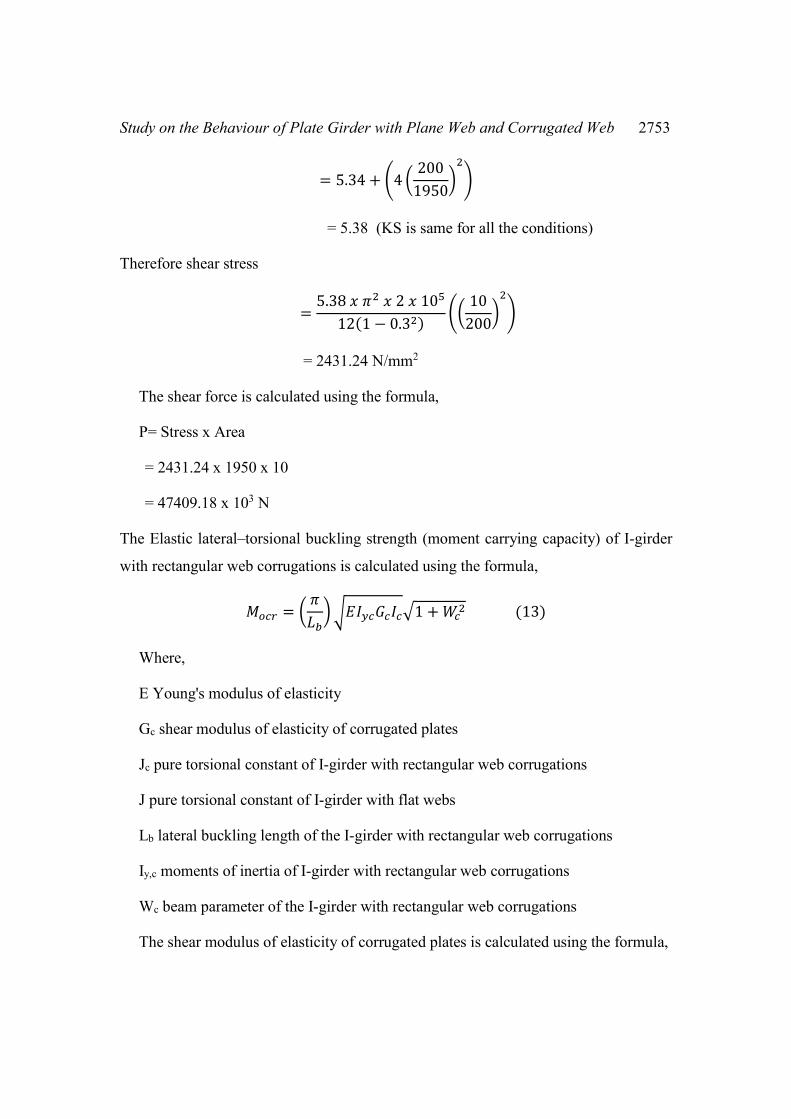
Study on the Behaviour of Plate Girder with Plane Web and Corrugated Web 2753
= 5.34 + (4 (200
1950)
2
)
= 5.38 (KS is same for all the conditions)
Therefore shear stress
=5.38 𝑥 𝜋2 𝑥 2 𝑥 105
12(1 − 0.32)((
10
200)
2
)
= 2431.24 N/mm2
The shear force is calculated using the formula,
P= Stress x Area
= 2431.24 x 1950 x 10
= 47409.18 x 103 N
The Elastic lateral–torsional buckling strength (moment carrying capacity) of I-girder
with rectangular web corrugations is calculated using the formula,
𝑀𝑜𝑐𝑟 = (𝜋
𝐿𝑏) √𝐸𝐼𝑦𝑐𝐺𝑐𝐼𝑐√1 + 𝑊𝑐
2 (13)
Where,
E Young's modulus of elasticity
Gc shear modulus of elasticity of corrugated plates
Jc pure torsional constant of I-girder with rectangular web corrugations
J pure torsional constant of I-girder with flat webs
Lb lateral buckling length of the I-girder with rectangular web corrugations
Iy,c moments of inertia of I-girder with rectangular web corrugations
Wc beam parameter of the I-girder with rectangular web corrugations
The shear modulus of elasticity of corrugated plates is calculated using the formula,

2754 R.Rajkumar, R.Aravindh, B.Gokula Krishanan & B.Mukul Anand
𝐺𝑐 =𝑎 + 𝑏
𝑎 + 𝑐𝐺 (14)
Where,
G is the shear modulus of the flat plates and (a+b) is the projection length of the actual
length (a+c)
𝐺 =𝐸
2(1 + 𝜈) (15)
=2𝑋105
2𝑋(1 + 0.3)
= 76923.07
Therefore Gc
=200 + 0
100 + 200 𝑥76923.07
= 51.283 x 10³ (Gc is same for all conditions)
The moment of inertia Iyccan be calculated using the formula,
𝐼𝑦𝑐 =𝑡𝑓𝑏𝑓(2𝑡𝑓𝑏𝑓
3 + 𝑡𝑤ℎ𝑤𝑏𝑓2 + 12𝑑2𝑡𝑤ℎ𝑤)
6(2𝑡𝑓𝑏𝑓 + 𝑡𝑤ℎ𝑤) (16)
= (40𝑥600)(2𝑥40𝑥6003+10𝑥1950𝑥6002+12𝑥1002𝑥10𝑥1950)
6(2𝑥40𝑥600+10𝑥1950)
= 1578.67 x 106 mm4
The torsional constant is calculated using the formula,
𝐽𝑐 = 2𝑏𝑓𝑡𝑓
3 + ℎ𝑡𝑤3
3 (17)
=2𝑥600𝑥403 + 1950𝑥103
3
= 26.25 x 10⁶

Study on the Behaviour of Plate Girder with Plane Web and Corrugated Web 2755
The beam parameter Wc is calculated using the formula,
𝑊𝑐 = (𝜋
𝐿𝑏) √
𝐸𝐶𝑤,𝑐
𝐺𝑐𝐽𝑐 (18)
Where,
Lb lateral buckling length of the I-girder with rectangular web corrugations
Jc pure torsional constant of I-girder with rectangular web corrugations
E Young's modulus of elasticity
Cw,c warping constant of I-girder with rectangular web corrugations
𝐶𝑤,𝑐 =ℎ𝑤
2 𝑡𝑓𝑏𝑓(6𝑡𝑓𝑏𝑓3+𝑡𝑤ℎ𝑤𝑏𝑓
2+12𝑑2𝑡𝑤ℎ𝑤)
24(6𝑡𝑓𝑏𝑓+𝑡𝑤ℎ𝑤)(19)
19502𝑥40𝑥600(6𝑥40𝑥6003+10𝑥1950𝑥6002+12𝑥1002𝑥10𝑥1950)
24(6𝑥40𝑥600+10𝑥1950)= 1.423 x 10¹⁵
Therefore Wc
= (𝜋
1000)√
2𝑥105𝑥1.43𝑥1015
51.283𝑥103𝑥26.25𝑥106
= 4.579
The moment carrying capacity Mocof the I section with rectangular corrugated web,
= (𝜋
1000) √(2𝑥105𝑥1578.67𝑥106𝑥51.283𝑥103𝑥26.25𝑥106)√1 + 4.5792
= 30361.72 x 106 Nmm
= 30361.72 kNm
Similarly, for 20mm thick plate
The shear stress is calculated using the formula,
𝜏𝑐𝑟 = 𝐾𝑠𝜋2𝐸
12(1 − 𝑣2)(
𝑡𝑤
𝑏)
2
(11)

2756 R.Rajkumar, R.Aravindh, B.Gokula Krishanan & B.Mukul Anand
=5.38 𝑥 𝜋2 𝑥 2 𝑥 105
12(1 − 0.32)((
20
200)
2
)
= 9724.99 N/mm2
The shear force is calculated using the formula,
P= Stress x Area
= 9724.99 x 1950 x 20
= 379274.79 x 103 N
The Elastic lateral–torsional buckling strength (moment carrying capacity) of I-girder
with rectangular web corrugations is calculated using the formula,
𝑀𝑜𝑐𝑟 = (𝜋
𝐿𝑏) √𝐸𝐼𝑦𝑐𝐺𝑐𝐼𝑐√1 + 𝑊𝑐
2 (13)
The moment of inertia Iyccan be calculated using the formula,
𝐼𝑦𝑐 =𝑡𝑓𝑏𝑓(2𝑡𝑓𝑏𝑓
3 + 𝑡𝑤ℎ𝑤𝑏𝑓2 + 12𝑑2𝑡𝑤ℎ𝑤)
6(2𝑡𝑓𝑏𝑓 + 𝑡𝑤ℎ𝑤) (16)
=(40𝑥600)(2𝑥40𝑥6003 + 20𝑥1950𝑥6002 + 12𝑥1002𝑥20𝑥1950)
6(2𝑥40𝑥600 + 20𝑥1950)
= 1655.17 x 106 mm4
The torsional constant is calculated using the formula,
𝐽𝑐 = 2𝑏𝑓𝑡𝑓
3 + ℎ𝑡𝑤3
3 (17)
=2𝑥600𝑥403 + 1950𝑥203
3
= 30.8 x 10⁶
Study on the Behaviour of Plate Girder with Plane Web and Corrugated Web 2757
The beam parameter Wc is calculated using the formula,
𝑊𝑐 = (𝜋
𝐿𝑏) √
𝐸𝐶𝑤,𝑐
𝐺𝑐𝐽𝑐 (18)
Where,
𝐶𝑤,𝑐 =ℎ𝑤
2 𝑡𝑓𝑏𝑓(6𝑡𝑓𝑏𝑓3+𝑡𝑤ℎ𝑤𝑏𝑓
2+12𝑑2𝑡𝑤ℎ𝑤)
24(6𝑡𝑓𝑏𝑓+𝑡𝑤ℎ𝑤) (19)
=19502𝑥40𝑥600(6𝑥40𝑥6003 + 20𝑥1950𝑥6002 + 12𝑥1002𝑥20𝑥1950)
24(6𝑥40𝑥600 + 20𝑥1950)
= 1.466 x 10¹⁵
Therefore Wc
= (𝜋
1000)√
2𝑥105𝑥1.466𝑥1015
51.283𝑥103𝑥30.8𝑥106
= 4.28
The moment carrying capacity Mocr of the I section with rectangular corrugated web,
= (𝜋
1000) √(2𝑥105𝑥1655.17𝑥106𝑥51.283𝑥103𝑥30.8𝑥106)√1 + 4.282
= 31574.33 kNm
Similarly, for 30mm thick plate
The shear stress is calculated using the formula,
𝜏𝑐𝑟 = 𝐾𝑠𝜋2𝐸
12(1 − 𝑣2)(
𝑡𝑤
𝑏)
2
(11)
=5.38 𝑥 𝜋2 𝑥 2 𝑥 105
12(1 − 0.32)((
30
200)
2
)
= 21881.24 N/mm2
The shear force is calculated using the formula,
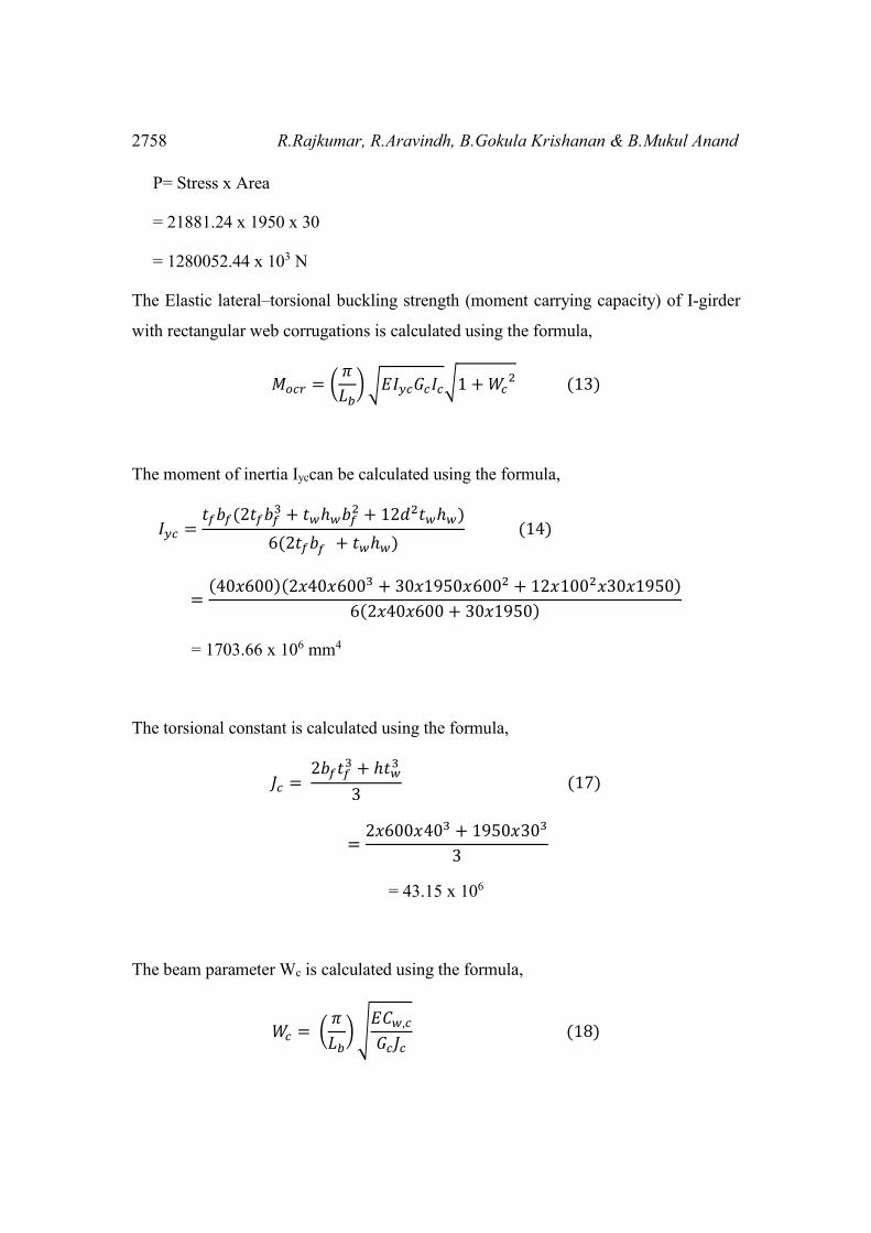
2758 R.Rajkumar, R.Aravindh, B.Gokula Krishanan & B.Mukul Anand
P= Stress x Area
= 21881.24 x 1950 x 30
= 1280052.44 x 103 N
The Elastic lateral–torsional buckling strength (moment carrying capacity) of I-girder
with rectangular web corrugations is calculated using the formula,
𝑀𝑜𝑐𝑟 = (𝜋
𝐿𝑏) √𝐸𝐼𝑦𝑐𝐺𝑐𝐼𝑐√1 + 𝑊𝑐
2 (13)
The moment of inertia Iyccan be calculated using the formula,
𝐼𝑦𝑐 =𝑡𝑓𝑏𝑓(2𝑡𝑓𝑏𝑓
3 + 𝑡𝑤ℎ𝑤𝑏𝑓2 + 12𝑑2𝑡𝑤ℎ𝑤)
6(2𝑡𝑓𝑏𝑓 + 𝑡𝑤ℎ𝑤) (14)
=(40𝑥600)(2𝑥40𝑥6003 + 30𝑥1950𝑥6002 + 12𝑥1002𝑥30𝑥1950)
6(2𝑥40𝑥600 + 30𝑥1950)
= 1703.66 x 106 mm4
The torsional constant is calculated using the formula,
𝐽𝑐 = 2𝑏𝑓𝑡𝑓
3 + ℎ𝑡𝑤3
3 (17)
=2𝑥600𝑥403 + 1950𝑥303
3
= 43.15 x 10⁶
The beam parameter Wc is calculated using the formula,
𝑊𝑐 = (𝜋
𝐿𝑏) √
𝐸𝐶𝑤,𝑐
𝐺𝑐𝐽𝑐 (18)
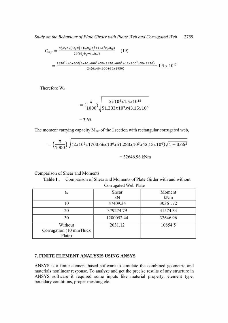
Study on the Behaviour of Plate Girder with Plane Web and Corrugated Web 2759
𝐶𝑤,𝑐 =ℎ𝑤
2 𝑡𝑓𝑏𝑓(6𝑡𝑓𝑏𝑓3+𝑡𝑤ℎ𝑤𝑏𝑓
2+12𝑑2𝑡𝑤ℎ𝑤)
24(6𝑡𝑓𝑏𝑓+𝑡𝑤ℎ𝑤) (19)
=19502𝑥40𝑥600(6𝑥40𝑥6003+30𝑥1950𝑥6002+12𝑥1002𝑥30𝑥1950)
24(6𝑥40𝑥600+30𝑥1950)= 1.5 x 10¹⁵
Therefore Wc
= (𝜋
1000)√
2𝑥105𝑥1.5𝑥1015
51.283𝑥103𝑥43.15𝑥106
= 3.65
The moment carrying capacity Mocr of the I section with rectangular corrugated web,
= (𝜋
1000) √(2𝑥105𝑥1703.66𝑥106𝑥51.283𝑥103𝑥43.15𝑥106)√1 + 3.652
= 32646.96 kNm
Comparison of Shear and Moments
Table I . Comparison of Shear and Moments of Plate Girder with and without Corrugated Web Plate
tw Shear kN
Moment kNm
10 47409.34 30361.72 20 379274.79 31574.33 30 1280052.44 32646.96
Without Corrugation (10 mmThick
Plate)
2031.12 10854.5
7. FINITE ELEMENT ANALYSIS USING ANSYS
ANSYS is a finite element based software to simulate the combined geometric and materials nonlinear response. To analyze and get the precise results of any structure in ANSYS software it required some inputs like material property, element type, boundary conditions, proper meshing etc.

2760 R.Rajkumar, R.Aravindh, B.Gokula Krishanan & B.Mukul Anand
7.1 FLOW CHART
The following flow chart describes the methodology for the software design and analysis of plate girders with and without corrugated webs.
Figure 4 . Flowchart for Analysis
7.2 DRAWING PROCEDURE
1) The section is drawn using Creo parametric software. 2) A suitable plane is chosen and the dimensions of the section are given. 3) Normal command is used to change the distance. 4) Extrude command is used for giving the thickness of the various sections. 5) To repeat the number of corrugations assembly command is used. 6) After drawing the I section and the corrugations assembly → coincide
command is used to join the I section and corrugations. 7) The file is saved in .igs format.
7.3. ANALYSIS OF PLATE GIRDER WITH PLANE WEB
1) The saved file is first imported 2) In the pre-processor command click the element option and click add solid.
GEOMETRY
ELEMENT TYPE
MATERIAL PROPERTIES
MESH DEFINITION
BOUNDARY CONDITONS
ANALYSIS
POST PROCESSING

Study on the Behaviour of Plate Girder with Plane Web and Corrugated Web 2761
3) For giving the material properties click on the material model command and choose structural →linear→ isotropic. Here the value of Young’s modulus and Poisson’s ratio are given.
4) The meshing is provided by clicking on the meshing tool command and choosing global→ 1 →pick all option.
5) Click on the analysis type option and click on new analysis→ static. 6) For giving support conditions, click on the key points option and choose
node option. After giving these commands on the bottom face of the section click the four corner node which denotes the simply supported condition.
7) For defining loads click on define loads option and choose apply structural on area→ force and moment→ center of section →250kN on the top face.
8) Click on the solution option and click on solve→ current L.S and ok. 9) Finally click on the general preprocessor command and click on the plot
result→ nodal solution →contour plot→ Von mises stress to get the results.
7.4. ANALYSIS OF PLATE GIRDER WITH CORRUGATED WEB
1) The saved file is first imported. 2) Click on the modeling option and choose operate→ Boolean →add
volume→ select all and click ok to connect the section as a whole mass. 3) In the preprocessor command click the element option and click add solid. 4) For giving the material properties click on the material model command and
choose structural→ linear →isotropic. Here the value of Young’s modulus and Poisson’s ratio are given.
5) The meshing is provided by clicking on the meshing tool command and choose global→ 1 →pick all option.
6) Click on the analysis type option and click on new analysis static. 7) For giving support conditions click on the key points option and choose
node option. After giving these commands on the bottom face of the section click the four-corner node which denotes the simply supported condition.
8) For defining loads click on define loads option and choose apply structural on area→ force and moment→ center of section →250kN on the top face.
9) Click on the solution option and click on solve→ current L.S and ok. 10) Finally click on the general preprocessor command and click on the plot
result→ nodal solution→ contour plot →Von mises stress to get the results
2762 R.Rajkumar, R.Aravindh, B.Gokula Krishanan & B.Mukul Anand
7.5. ANALYSIS RESULTS
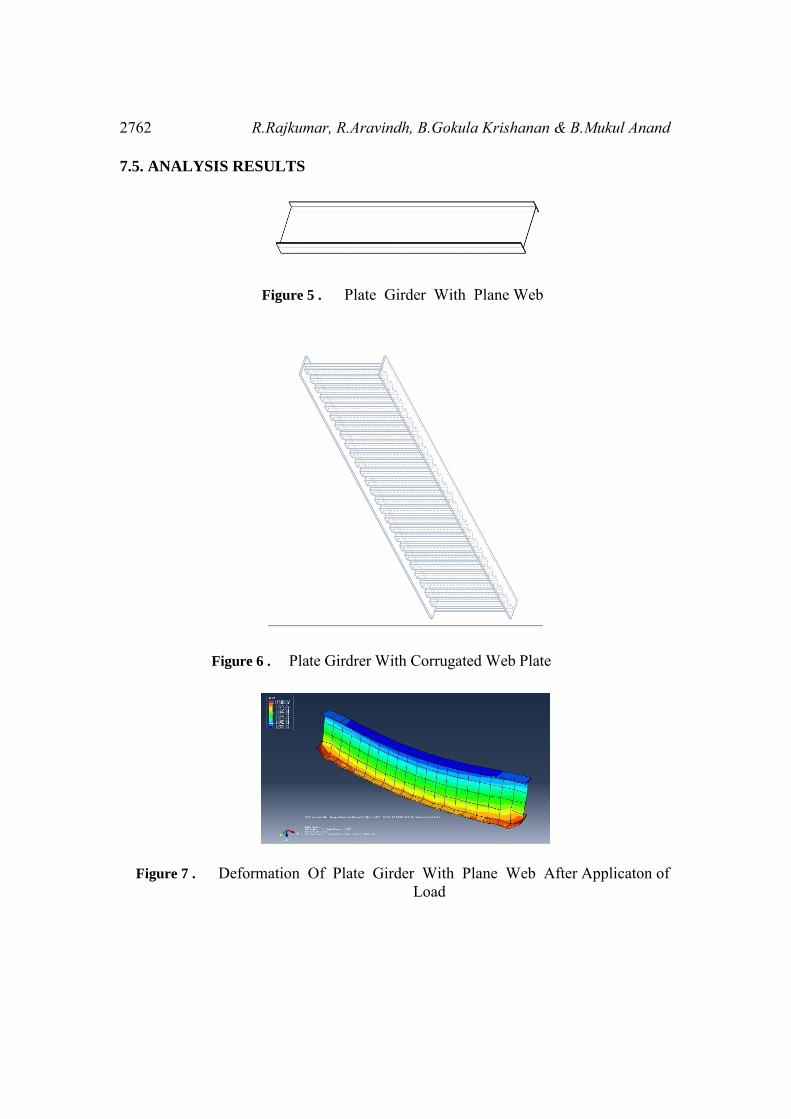
Figure 5 . Plate Girder With Plane Web
Figure 6 . Plate Girdrer With Corrugated Web Plate
Figure 7 . Deformation Of Plate Girder With Plane Web After Applicaton of Load

Study on the Behaviour of Plate Girder with Plane Web and Corrugated Web 2763
Figure 8 . Deformation Of Plate Girder With 10mm Thick Corrugated Plate
Figure 9 . Deformation Of Plate Girder With 20mm Thick Corrugated Plate
Figure 10 . Deformation Of Plate Girder With 30mm Thick Corrugated Plate
8. CONCLUSION
Both shear force and moments of varying web thickness are compared. From the results, it is found that plate girder with corrugated webs are more efficient than the plate girder with plane web. The moment carrying capacity of the plate girder with corrugated web is found to be 64% higher in the case of 10 mm thick plate than that of the plate girder with plane web. Similar results were obtained with varying thicknesses of the plates. Moreover the shear taking capacity of the plate girder with corrugated web is significant when compared with the plate girder with plane web.
2764 R.Rajkumar, R.Aravindh, B.Gokula Krishanan & B.Mukul Anand
REFERENCES
[1] Basher M, Shanmugam N.E, Khalim A.R. Horizontally curved composite plate girders with trapezoidally corrugated webs. In: Journal of Constructional Steel Research 67 (2011) 947–956.
[2] Easley JT, McFarland DE. Buckling of light-gauge corrugated metal shear diaphragms. Journal of the Structural Division, ASCE 1969;95:1497–516.
[3] Easley JT. Buckling formulas for corrugated metal shear diaphragms. Journal of the Structural Division, ASCE 1975;ST7:1403–17.
[4] Elgaaly M, Hamilton RW, Seshadri A. Shear strength of beams with corrugated webs. Journal of Structural Engineering, ASCE 1996;122(4):390–8.
[5] Elgaaly M, Seshadri A, Hamilton RW. Bending strength of beams with corrugated webs. Journal of Structural Engineering, ASCE 1997;123(6):772– 82.
[6] Elgaaly M, Seshadri A. Girders with corrugated webs under partial compressive edge loading. Journal of Structural Engineering, ASCE 1997;123(6):783–91.
[7] Elgaaly M, Seshadri A. Depicting the behavior of girders with corrugated webs up to failure using non-linear finite element analysis. Advances in Engineering Software 1998;29(3– 6):195–208.
[8] Jamali S, “Lateral Torsional Buckling of Trapezoid Web Profile,” MSc. Thesis, Universiti Teknologi Malaysia (2004).
[9] Khalid Y.A., C.L. Chan, B.B. Sahari, A.M.S. Hamouda.”Bending behaviour of corrugated web beams”, Journal of Materials Processing Technology 150 (2004) 242–254.
[10] Luo R, Edlund B. Buckling analysis of trapezoidally corrugated panels using spline finite strip method. Thin-Walled Structures 1994;18:209–24.
[11] Luo R, Edlund B. Shear capacity of plate girders with trapezoidally corrugated webs. Thin-Walled Structures 1996;26:19–44.
[12] IS 800:2007, Code of practice for general construction in steel, Bureau of Indian Standards, New Delhi.