study on cutting forces and surface …the simulation of the cutting process using the deform 2d...
TRANSCRIPT
ACADEMIC JOURNAL OF MANUFACTURING ENGINEERING, VOL. 17, ISSUE 4/2019
182
STUDY ON CUTTING FORCES AND SURFACE QUALITY IN
TURNING C45 STEEL
Adrian TRIF1 and
Alina-Ioana POPAN
2
Department of Manufacturing Engineering, Technical University of Cluj-Napoca, Romania,
e-mail: [email protected]
Department of Manufacturing Engineering, Technical University of Cluj-Napoca, Romania,
e-mail: [email protected]
ABSTRACT: This study aims to present the main theoretical and practical aspects
regarding the study of roughness and cutting forces in the case of the external turning process
of C45 carbon steel. The content of the study presents general data on the turning operation,
various roughness - obtained from the turning process of C45 carbon steel, how the cutting
force and roughness forces are influenced by the cutting speed and the depth of the cut, but also
the simulation of the cutting process using the DEFORM 2D software.
KEYWORDS: steel, turning , forces, roughness, simulation
1 INTRODUCTION
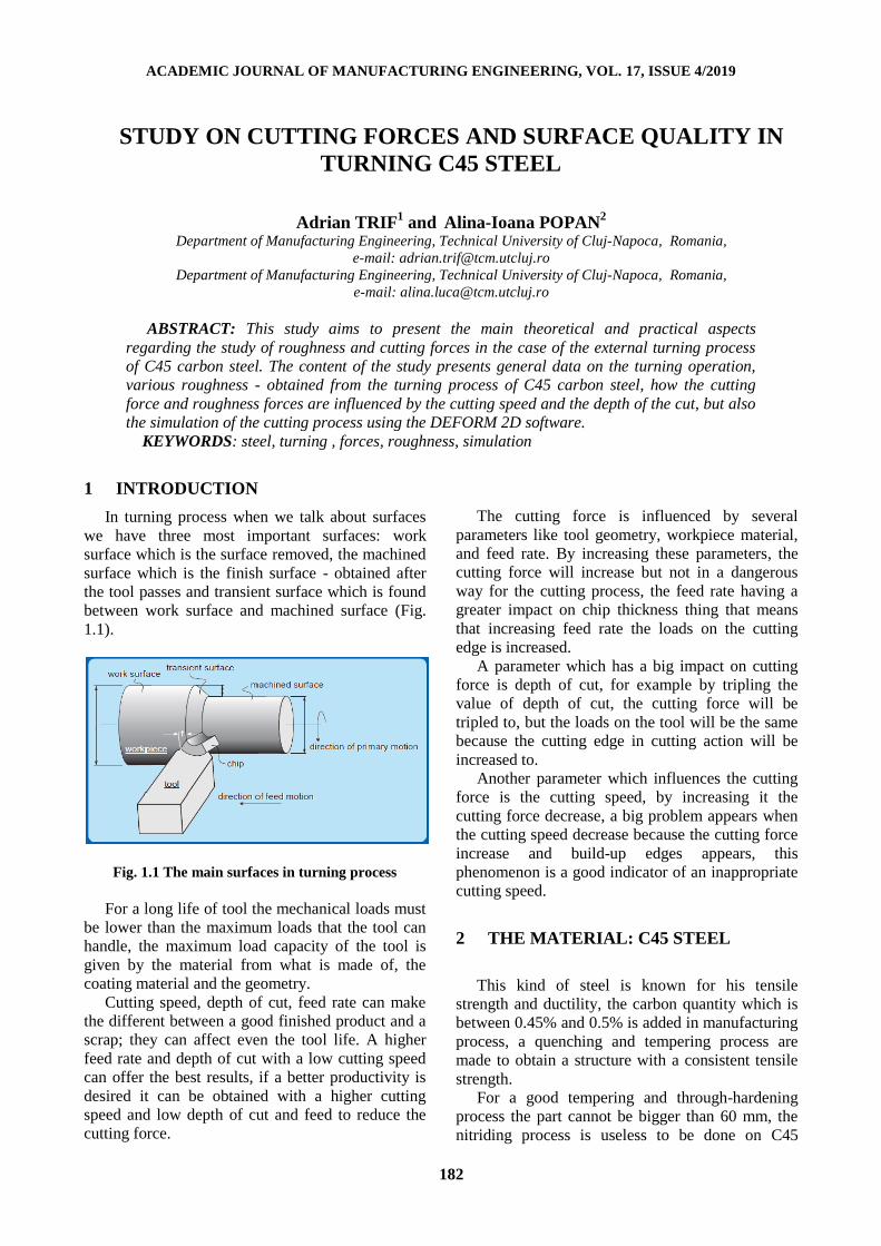
In turning process when we talk about surfaces
we have three most important surfaces: work
surface which is the surface removed, the machined
surface which is the finish surface - obtained after
the tool passes and transient surface which is found
between work surface and machined surface (Fig.
1.1).
Fig. 1.1 The main surfaces in turning process
For a long life of tool the mechanical loads must
be lower than the maximum loads that the tool can
handle, the maximum load capacity of the tool is
given by the material from what is made of, the
coating material and the geometry.
Cutting speed, depth of cut, feed rate can make
the different between a good finished product and a
scrap; they can affect even the tool life. A higher
feed rate and depth of cut with a low cutting speed
can offer the best results, if a better productivity is
desired it can be obtained with a higher cutting
speed and low depth of cut and feed to reduce the
cutting force.
The cutting force is influenced by several
parameters like tool geometry, workpiece material,
and feed rate. By increasing these parameters, the
cutting force will increase but not in a dangerous
way for the cutting process, the feed rate having a
greater impact on chip thickness thing that means
that increasing feed rate the loads on the cutting
edge is increased.
A parameter which has a big impact on cutting
force is depth of cut, for example by tripling the
value of depth of cut, the cutting force will be
tripled to, but the loads on the tool will be the same
because the cutting edge in cutting action will be
increased to.
Another parameter which influences the cutting
force is the cutting speed, by increasing it the
cutting force decrease, a big problem appears when
the cutting speed decrease because the cutting force
increase and build-up edges appears, this
phenomenon is a good indicator of an inappropriate
cutting speed.
2 THE MATERIAL: C45 STEEL
This kind of steel is known for his tensile
strength and ductility, the carbon quantity which is
between 0.45% and 0.5% is added in manufacturing
process, a quenching and tempering process are
made to obtain a structure with a consistent tensile
strength.
For a good tempering and through-hardening
process the part cannot be bigger than 60 mm, the
nitriding process is useless to be done on C45

ACADEMIC JOURNAL OF MANUFACTURING ENGINEERING, VOL. 17, ISSUE 4/2019
183
because the alloying elements are not suitable for
this process.
The machinability of C45 is is influenced by
some factors like microstructure, content of carbon,
sulfur, manganese, for example a high quantity of
sulfur allow a high feed reducing the strain
hardening of the chip and maintaining a consistent
build up edge on the tool.
Fig. 2.1 Chemical composition of C45 steel
The used insert is CCMT 09T304 FG (TT5080):
Fig. 2.2. The workpiece and the insert
●General information about roughness in turning
of C45 carbon steel
The surface roughness is an important parameter
in every machining process, this parameter affects
different characteristics like tribological one,
frictional and most important, opinion the assembly
capabilities, the surface roughness is influenced by
different parameters like:
- Tool geometry;
- Depth of cut;
- Cutting speed;
- Feed rate;
- Workpiece’s microstructure;
- Rigidity of the machine;
The surface roughness has his impact to, on the
performance of produced machines, efficiency,
mechanical life, resistance against environmental
factors.
Lot of studies present by the experts show that
the geometry of the insert, the cutting force, feed
rate, have a major impact on the roughness of the
finished surface.
3 EXPERIMENTAL WORK
● Basic informations about experimental work
The experiment that consists in the turning
process of a carbon steel C45 shaft with the
diameter of 50 mm was rolled out at different depth
of cut, cutting speed and same feed rate in order to
analyze the cutting force and the surface roughness
resulted.
The machine used in the experiment was a
classical lathe model SPF-1500P from
Technical University of Cluj-Napoca, Faculty of
Machine Building.
The temperatures of cutting area in turning
process was also measured with the help Optris
Infrared Thermometer LS, the thermometer is
presented in Fig. 3.1, with an accuracy of ±2.5 °C (-
35 to -20°C), ±1.5 °C (-19.9 to 20°C), ±0.75 °C
(20.1 to 100°C), ±0.75 °C (100.1 to 900°C)
Fig. 3.1 Optris Infrared Thermometer LS
●The experiment
The experiment consists of twelve attempts, in
every single one the depth of cut and cutting speed
being different, the values varying for depth of cut
from 0.5 to 2 mm and for cutting speed from 250 to
1220 rot/min.
●The cutting process
The cutting force and temperature were
measured with the help of “XKM 2000” which is
the soft of the TELC DKM 2010 dynamometers
through which the cutting force during the
machining process was represented in form of a
graph and with “Optris Connect” which is the
ACADEMIC JOURNAL OF MANUFACTURING ENGINEERING, VOL. 17, ISSUE 4/2019
184
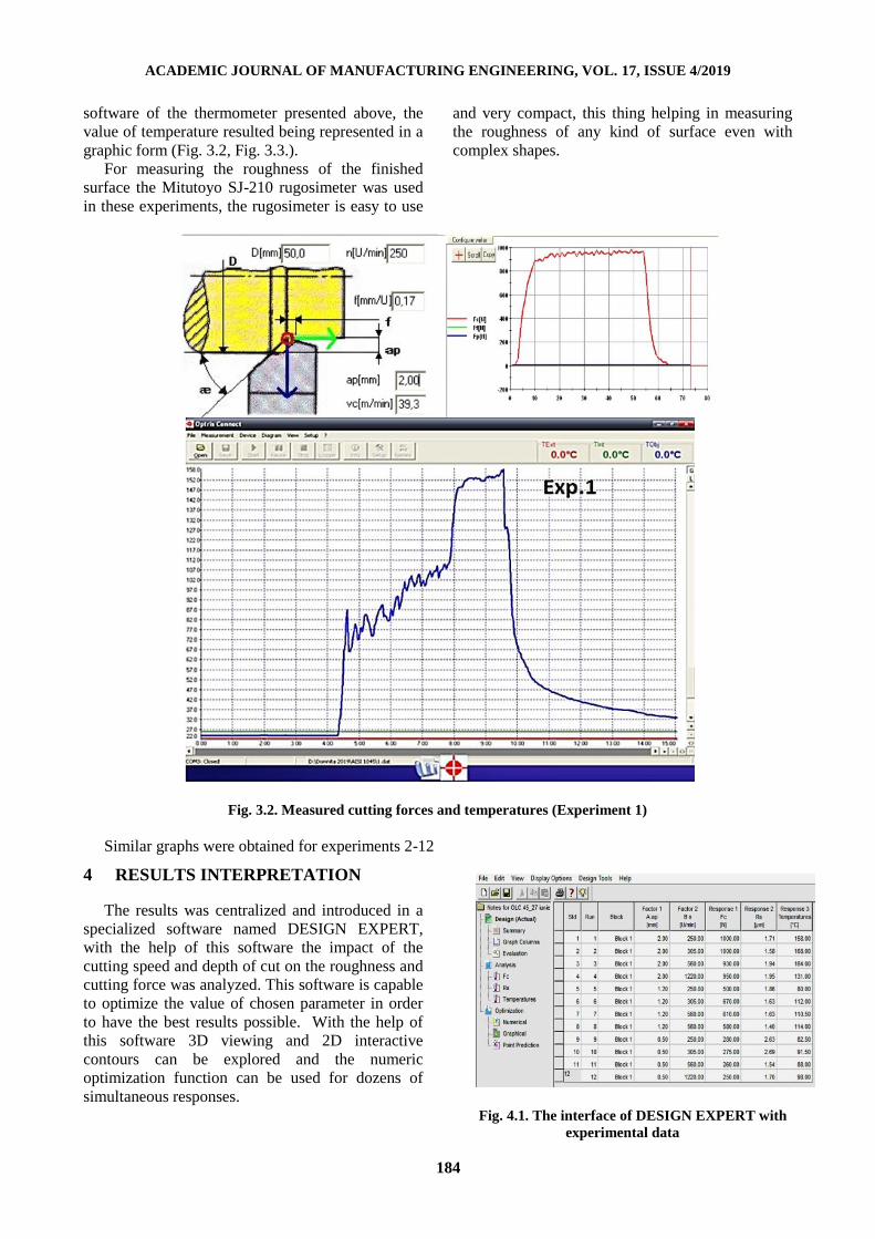
software of the thermometer presented above, the
value of temperature resulted being represented in a
graphic form (Fig. 3.2, Fig. 3.3.).
For measuring the roughness of the finished
surface the Mitutoyo SJ-210 rugosimeter was used
in these experiments, the rugosimeter is easy to use
and very compact, this thing helping in measuring
the roughness of any kind of surface even with
complex shapes.
Fig. 3.2. Measured cutting forces and temperatures (Experiment 1)
Similar graphs were obtained for experiments 2-12
4 RESULTS INTERPRETATION
The results was centralized and introduced in a
specialized software named DESIGN EXPERT,
with the help of this software the impact of the
cutting speed and depth of cut on the roughness and
cutting force was analyzed. This software is capable
to optimize the value of chosen parameter in order
to have the best results possible. With the help of
this software 3D viewing and 2D interactive
contours can be explored and the numeric
optimization function can be used for dozens of
simultaneous responses.
Fig. 4.1. The interface of DESIGN EXPERT with
experimental data
ACADEMIC JOURNAL OF MANUFACTURING ENGINEERING, VOL. 17, ISSUE 4/2019
185
The mathematical model for the Design Expert
software is ANOVA, and the graphical analyzes
will be presented below.
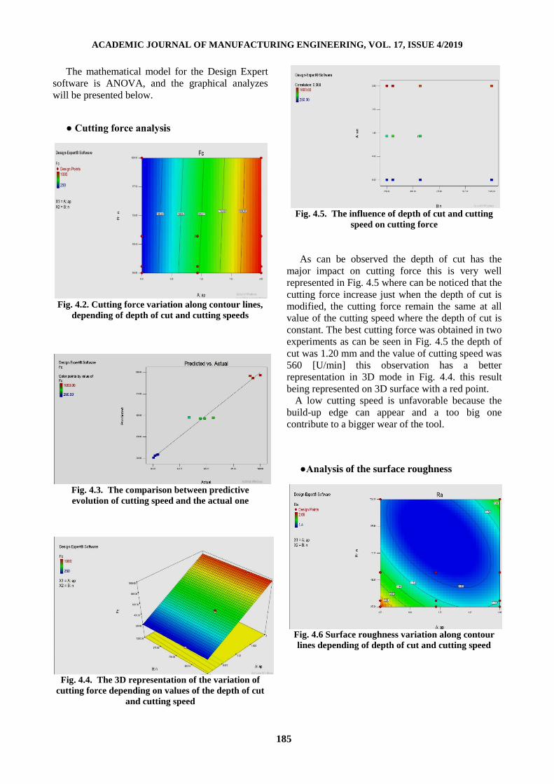
● Cutting force analysis
Fig. 4.2. Cutting force variation along contour lines,
depending of depth of cut and cutting speeds
Fig. 4.3. The comparison between predictive
evolution of cutting speed and the actual one
Fig. 4.4. The 3D representation of the variation of
cutting force depending on values of the depth of cut
and cutting speed
Fig. 4.5. The influence of depth of cut and cutting
speed on cutting force
As can be observed the depth of cut has the
major impact on cutting force this is very well
represented in Fig. 4.5 where can be noticed that the
cutting force increase just when the depth of cut is
modified, the cutting force remain the same at all
value of the cutting speed where the depth of cut is
constant. The best cutting force was obtained in two
experiments as can be seen in Fig. 4.5 the depth of
cut was 1.20 mm and the value of cutting speed was
560 [U/min] this observation has a better
representation in 3D mode in Fig. 4.4. this result
being represented on 3D surface with a red point.
A low cutting speed is unfavorable because the
build-up edge can appear and a too big one
contribute to a bigger wear of the tool.
●Analysis of the surface roughness
Fig. 4.6 Surface roughness variation along contour
lines depending of depth of cut and cutting speed
ACADEMIC JOURNAL OF MANUFACTURING ENGINEERING, VOL. 17, ISSUE 4/2019
186
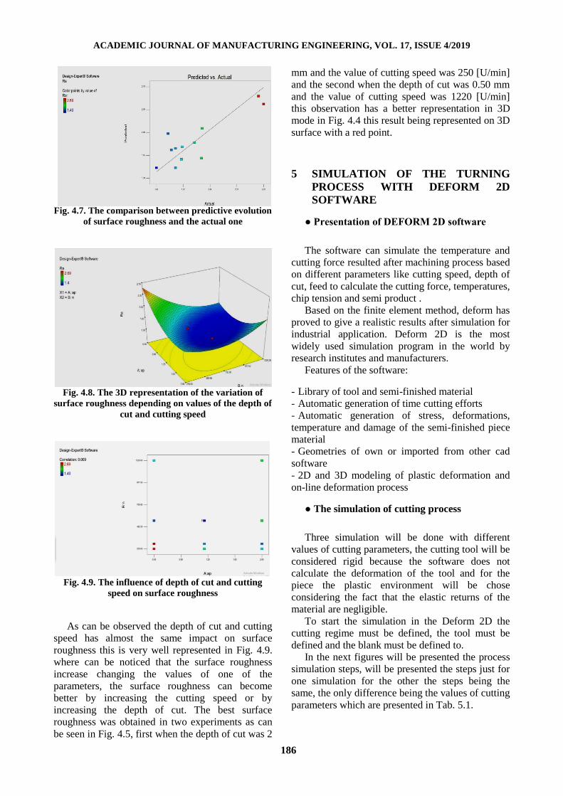
Fig. 4.7. The comparison between predictive evolution
of surface roughness and the actual one
Fig. 4.8. The 3D representation of the variation of
surface roughness depending on values of the depth of
cut and cutting speed
Fig. 4.9. The influence of depth of cut and cutting
speed on surface roughness
As can be observed the depth of cut and cutting
speed has almost the same impact on surface
roughness this is very well represented in Fig. 4.9.
where can be noticed that the surface roughness
increase changing the values of one of the
parameters, the surface roughness can become
better by increasing the cutting speed or by
increasing the depth of cut. The best surface
roughness was obtained in two experiments as can
be seen in Fig. 4.5, first when the depth of cut was 2
mm and the value of cutting speed was 250 [U/min]
and the second when the depth of cut was 0.50 mm
and the value of cutting speed was 1220 [U/min]
this observation has a better representation in 3D
mode in Fig. 4.4 this result being represented on 3D
surface with a red point.
5 SIMULATION OF THE TURNING
PROCESS WITH DEFORM 2D
SOFTWARE
● Presentation of DEFORM 2D software
The software can simulate the temperature and
cutting force resulted after machining process based
on different parameters like cutting speed, depth of
cut, feed to calculate the cutting force, temperatures,
chip tension and semi product .
Based on the finite element method, deform has
proved to give a realistic results after simulation for
industrial application. Deform 2D is the most
widely used simulation program in the world by
research institutes and manufacturers.
Features of the software:
- Library of tool and semi-finished material
- Automatic generation of time cutting efforts
- Automatic generation of stress, deformations,
temperature and damage of the semi-finished piece
material
- Geometries of own or imported from other cad
software
- 2D and 3D modeling of plastic deformation and
on-line deformation process
● The simulation of cutting process
Three simulation will be done with different
values of cutting parameters, the cutting tool will be
considered rigid because the software does not
calculate the deformation of the tool and for the
piece the plastic environment will be chose
considering the fact that the elastic returns of the
material are negligible.
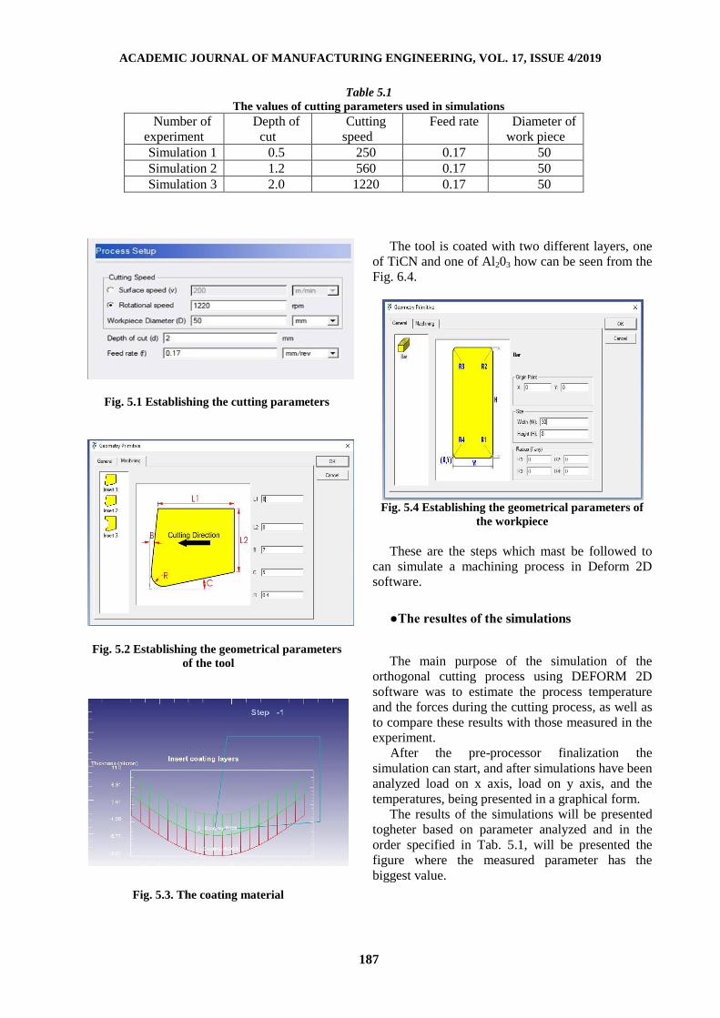
To start the simulation in the Deform 2D the
cutting regime must be defined, the tool must be
defined and the blank must be defined to.
In the next figures will be presented the process
simulation steps, will be presented the steps just for
one simulation for the other the steps being the
same, the only difference being the values of cutting
parameters which are presented in Tab. 5.1.
ACADEMIC JOURNAL OF MANUFACTURING ENGINEERING, VOL. 17, ISSUE 4/2019
187
Table 5.1
The values of cutting parameters used in simulations
Number of
experiment
Depth of
cut
Cutting
speed
Feed rate Diameter of
work piece
Simulation 1 0.5 250 0.17 50
Simulation 2 1.2 560 0.17 50
Simulation 3 2.0 1220 0.17 50
Fig. 5.1 Establishing the cutting parameters
Fig. 5.2 Establishing the geometrical parameters
of the tool
Fig. 5.3. The coating material
The tool is coated with two different layers, one
of TiCN and one of Al203 how can be seen from the
Fig. 6.4.
Fig. 5.4 Establishing the geometrical parameters of
the workpiece
These are the steps which mast be followed to
can simulate a machining process in Deform 2D
software.
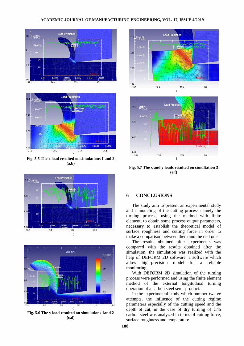
●The resultes of the simulations
The main purpose of the simulation of the
orthogonal cutting process using DEFORM 2D
software was to estimate the process temperature
and the forces during the cutting process, as well as
to compare these results with those measured in the
experiment.
After the pre-processor finalization the
simulation can start, and after simulations have been
analyzed load on x axis, load on y axis, and the
temperatures, being presented in a graphical form.
The results of the simulations will be presented
togheter based on parameter analyzed and in the
order specified in Tab. 5.1, will be presented the
figure where the measured parameter has the
biggest value.
ACADEMIC JOURNAL OF MANUFACTURING ENGINEERING, VOL. 17, ISSUE 4/2019
188
a
b
Fig. 5.5 The x load resulted on simulations 1 and 2
(a,b)
c
d
Fig. 5.6 The y load resulted on simulations 1and 2
(c,d)
e
f
Fig. 5.7 The x and y loads resulted on simultation 3
(e,f)
6 CONCLUSIONS
The study aim to present an experimental study
and a modeling of the cutting process namely the
turning process, using the method with finite
element, to obtain some process output parameters,
necessary to establish the theoretical model of
surface roughness and cutting force in order to
make a comparison between them and the real one.
The results obtained after experiments was
compared with the results obtained after the
simulation, the simulation was realized with the
help of DEFORM 2D software, a software which
allow high-precision model for a reliable
monitoring.
With DEFORM 2D simulation of the turning
process were performed and using the finite element
method of the external longitudinal turning
operation of a carbon steel semi-product.
In the experimental study which number twelve
attempts, the influence of the cutting regime
parameters especially of the cutting speed and the
depth of cut, in the case of dry turning of C45
carbon steel was analyzed in terms of cutting force,
surface roughness and temperature.

ACADEMIC JOURNAL OF MANUFACTURING ENGINEERING, VOL. 17, ISSUE 4/2019
189
From the results obtained in this work and based
on current knowledge, the following conclusion can
be derived:
- In this paper is related the characteristics of the
turning process, which presents the regime in terms
of cutting force and surface roughness at external
turning.
- The purpose of this work was to know how the
behavior of C45 carbon steel from the point of view
of cutting force and the surface roughness resulted.
- In term of cutting force, was observed that the
depth of cut has the biggest impact on this
parameter, even at high or low cutting speed the
cutting force is pretty constant, but by modifying
the depth of cut the cutting force modify sizably
from one value of this parameter to another, to
improve the cutting force the following steps are
recommended:
Reduce the depth of cut
Increase the cutting speed
-The temperature of the simulation process was
similar to the temperature measured using the
optical pyrometer
- The surface roughness is influenced pretty equal
by both parameters, the cutting speed and the depth
of cut, it was observed that it was obtained a good
surface quality when the cutting speed had a higher
value and the depth of cut had a lower one, a bad
surface roughness was observed when the depth of
cut and the cutting speed had both a low value, to
improve the surface quality the following steps are
recommended:
A correlation between the cutting speed and the
depth of cut is important to exist
Increase the cutting speed
Increase the depth of cut
7 REFERENCES
[1] A. Esteves Correiaa, J. Paulo Davimb (2011)
„Surface roughness measurement in turning carbon
steel AISI 1045 using wiper inserts” Journal of the
International Measurement Confederation.
[2] Abouelatta, O.B., Madl, J., (2001) „Surface
Roughness Prediction Based on Cutting Parameters
and Tool Vibrations in Turning Operations”,
Journal of Materials Processing Technology,
118:p269/277.
[3] Andrew Y., C. Nee „Handbook of
Manufacturing Engineering and Technology”
Faculty of Engineering, Mechanical Engineering
DepartmentNational University of Singapore.
[4] Anirban Bhattacharya, Santanu Das, P.
Majumder, Ajay Batish (2008) „Estimating the
effect of cutting parameters on surface finish and
power consumption during high speed machining of
AISI 1045 steel using Taguchi design and
ANOVA” German Academic Society for
Production Engineering (WGP).
[5] Anselmetti, B., Chep, A. and Mognol, P. (1995)
„Minimal database for the cutting parameters in con
manufacturing systems”, International Journal of
Computer Integrated Manufacturing.
[6] Anselmo Eduardo Diniz, Adilson Jose de
Oliveira (2004) „Optimizing the use of dry cutting
in rough turning steel operations” International
Journal of Machine Tools & Manufacturs.
[7] Anselmo Eduardo Diniz, Ricardo Micaroni
(2002) „Cutting conditions for finish turning
process aiming: the use of dry cutting”,
International Journal of Machine Tools &
Manufacture 42 (2002) 899–904.
[8] Arsecularame, J.; Mathew, P.; and Oxley, P.L.B.
(1995). "Prediction of chip flow direction and
cutting forces in oblique machining with nose
radius tools." Journal of Engg. Manufacture.
[9] Astakhov, V.P. (2006) „Tribology of Metal
Cutting, London: Elsevier”.
[10] Benardos, P.G., Vosniakos, G.-C., (2003),
„Predicting Surface Roughness in Machining: A
Review, International Journal of Machine Tools and
Manufacture” 43/8: 833–844.
[11] Boothroyd, G. and Knight, W.A. (2006)
„Fundamentals of Machining and Machine Tools”
3rd edn, Boca Raton, FL: CRC Press.432-440.
[12] C.Y. Niana, W.H. Yangb, Y.S. Tarng (1998)
„Optimization of turning operations with multiple
performance characteristics”, Journal of Materials
Processing Technology.
[13] Devries, W.R. (1992) „Analysis of Material
Removal Processes” New York: Springer Verlag.
[14] F. Klocke, W. Lortz, D. Trauth (2017)
„Analysis of the dynamic chip formation process in
turning” International Journal of Mechanical
Sciences.
[15] G. G. Ye, S. F. Xue, W. Ma, M. Q. Jiang, Z.
Ling, X. H. Tong, L. H. Dai (2011) „Cutting AISI
1045 steel at very high speeds” International
Journal of Machine Tools & Manufacture.
[16] I. Popescu, C.I. Pascu, „Roughness at turning,
Sitech Publishing House Craiova” 2010, ch.7.
[17] International Standard ISO 3002–1 1982. Basic
quantities in cutting and grinding. Part 1: Geometry
of the active part of cutting tools – general terms,
reference systems, tool and working angles, chip
breakers”. 123-125.
[18] Ramesh Singh (2015) “Applied Welding
Engineering 2nd Edition, Chapter 6 Classification
of Steel”.
ACADEMIC JOURNAL OF MANUFACTURING ENGINEERING, VOL. 17, ISSUE 4/2019
190
[19] Robson Bruno Dutra Pereira, Durval Uchôas
Braga, Frederico Ozanan Nevez, Alex Sander
Chaves da Silva (2013) „Analysis of surface
roughness and cutting force when turning AISI
1045 steel with grooved tools through Scott–Knott
method” International Journal of Advanced
Manufacturing Technology.
[20] S. A. Iqbal, P T Mativenga, and M. A. Sheikh
(2007) „Characterization of machining of AISI
1045 steel over a wide range of cutting speeds. Part
1: investigation of contact phenomena” Proc.
IMechE Vol. 221 Part B: J. Engineering
Manufacture.
[21] Steven E. Hughes (2009) „A Quick Guide to
Welding and Weld Inspection, Chapter 4 Materials
and Their Weldability”.
[22] T. Segreto, A. Simeone, R.Teti (2012) “Chip
Form Classification in Carbon Steel Turning
through Cutting Force Measurement and Principal
Component Analysis”.
[23] Tadeusz Leppert (2011) “Effect of cooling and
lubrication conditions on surface topography And
turning process of C45 steel”, International Journal
of Machine Tools & Manufacture.
[24] W. Bouzid Saï, J.L. Lebrun ”Influence of
finishing by burnishing on surface characteristics”
Journal of Materials Engineering and Performance
12 (1) (2003) .225-230
[25] W.H. Yang, Y.S. Tarng (1997) “Design
optimization of cutting parameters for turning
operations based on the Taguchi method”.
[26] Young Kug Hwang and Choon Man Lee
(2010) “Surface roughness and cutting force
prediction in MQL and wet turning process of AISI
1045 using design of experiments”.
[27] https://en.wikipedia.org/wiki/Steel
[28] https://bernhard.nepelius.at/en/woodturning-
jigs-manuals-techniques/history-of-woodturning/
[29]http://14.139.172.204/nptel/CSE/Web/1121010
05/images/lec3-5.html
[30]http://ecoursesonline.iasri.res.in/mod/page/view
.php?id=98862
[31]https://www.usi.edu/science/engineering/macha
sst/englathe/elath6.htm
[32] https://en.wikipedia.org/wiki/Bloomery
[33]https://www.tf.uni-
kiel.de/matwis/amat/iss/kap_a/illustr/ia_2_4.html
[34] https://en.wikipedia.org/wiki/Pig_iron
[35]https://www.manufacturingguide.com/en/ordlist
a/chip-breaking
[36]http://www.taegutectimes.com/New_Products_
5/EAET/eaet.html
[37]https://bads.lt/wp-
content/uploads/2019/01/Proma-leidinys.pdf
[38]https://uk.rs-online.com/web/p/infrared-
thermometers/0382927/