study on masonry walls with trees - civil study on masonry walls with trees geo report no. 257 c.m....
TRANSCRIPT

STUDY ON MASONRY WALLS
WITH TREES
GEO REPORT No. 257
C.M. Wong & Associates Limited & C.Y. Jim
GEOTECHNICAL ENGINEERING OFFICE
CIVIL ENGINEERING AND DEVELOPMENT DEPARTMENT
THE GOVERNMENT OF THE HONG KONG
SPECIAL ADMINISTRATIVE REGION

STUDY ON MASONRY WALLS
WITH TREES
GEO REPORT No. 257
C.M. Wong & Associates Limited & C.Y. Jim
This report was prepared by C.M. Wong & Associates Limited and C.Y. Jim in
November 2005 under Consultancy Agreement No. CE 11/2004(GE)
for the sole and specific use of the Government of the
Hong Kong Special Administrative Region

- 2 -
© The Government of the Hong Kong Special Administrative Region First published, January 2011 Prepared by: Geotechnical Engineering Office, Civil Engineering and Development Department, Civil Engineering and Development Building, 101 Princess Margaret Road, Homantin, Kowloon, Hong Kong.

- 3 -
PREFACE
In keeping with our policy of releasing information which may be of general interest to the geotechnical profession and the public, we make available selected internal reports in a series of publications termed the GEO Report series. The GEO Reports can be downloaded from the website of the Civil Engineering and Development Department (http://www.cedd.gov.hk) on the Internet. Printed copies are also available for some GEO Reports. For printed copies, a charge is made to cover the cost of printing. The Geotechnical Engineering Office also produces documents specifically for publication. These include guidance documents and results of comprehensive reviews. These publications and the printed GEO Reports may be obtained from the Government’s Information Services Department. Information on how to purchase these documents is given on the second last page of this report. R.K.S. Chan
Head, Geotechnical Engineering Office January 2011
- 4 -
EXECUTIVE SUMMARY C.M. Wong & Associates Ltd (CMWAL) was appointed by the Geotechnical Engineering Office (GEO) of the Civil Engineering and Development Department (CEDD) to conduct a study on masonry walls. The task is part of Agreement No. CE 11/2004 (GE), 10-year Extended LPM Project, Phase 5, Package E, Tai Po, Landslip Preventive Works on Government Slopes and Related Studies - Investigation, Design and Construction. The Brief for the Special Task requires CMWAL, with the support of a tree specialist, to conduct a study on the methods of upgrading masonry walls with the objective of preserving the masonry blocks and existing trees thereon as far as possible. This study of this special task commenced in November 2004. Professor C.Y. Jim of the Department of Geography, HKU, was appointed as the tree specialist. This study aims to assess the effects of wall trees on masonry walls. The stability of wall trees was not studied. This study included literature review, site inspections and information search. Based on the study, if trees grow on masonry walls, tree roots have minimal harmful effect and some beneficial effect on the stability of masonry walls. Due to the difficulty in quantifying the effect of roots, it may be ignored during stability analysis of masonry walls with trees. Surcharge of wall trees were found to have adverse effect on the stability of masonry walls. Wind forces on wall trees may cause additional sliding forces and overturning moments to act on the masonry walls. In the assessment of stability of retaining wall with trees, professional judgement should be exercised regarding whether the root anchorage is strong enough to sustain the design wind forces. If not, the effects of wind forces on wall trees could be ignored as far as the consequential effect on masonry walls is concerned. In order to upgrade substandard masonry walls with the existing trees preserved and existing masonry patterns retained, installation of soil nails, construction of hand-dug caissons, flying buttresses (where space permits) or a combination of the methods is recommended under different site conditions. Safety standards for checking the stability of masonry walls with trees are also recommended in this report. Special measures should be carried out during the upgrading of masonry walls that deserve preservation of the existing trees and the existing masonry patterns. The recommended special measures are presented in this report.

- 5 -
CONTENTS
Page No.
Title Page 1 PREFACE 3 EXECUTIVE SUMMARY 4 CONTENTS 5 1. INTRODUCTION 9
1.1 Summary of the Brief Requirements 9
1.2 Main Tasks of the Study 9
1.3 Outline of the Study 9 2. EXISTING TREES GROWING ON MASONRY WALLS IN 10 HONG KONG
2.1 Wall Trees in Hong Kong 10
2.2 Wall Tree Species 12 3. EFFECTS OF EXISTING TREES GROWING ON A MASONRY 13 WALL
3.1 Effects of Tree Roots 14
3.1.1 Effect of Tree Roots on Masonry Block Integrity 14
3.1.1.1 Strangler Rooting Habit of Banyans 14
3.1.1.2 Banyans as Pre-adapted Wall Trees 15
3.1.1.3 Co-existence between Banyan Roots and 16 Walls
3.1.1.4 Banyan Roots As a Wall Stabilizing Force 16
3.1.2 Effect of Tree Roots on Soil behind Retaining Walls 17
3.1.2.1 Root Strengthening 17
3.1.2.2 Tree Root Decay 17
3.1.2.3 Quantifying Root Strengthening Effect 18
3.1.3 Relevant Wall Failures 18
3.1.3.1 Search for Relevant Wall Failures 18
3.1.3.2 Records of Relevant Wall Failures 21
- 6 -
Page No.
3.1.4 Recommendations 25
3.2 Effects of Tree Stem 25
3.2.1 Surcharge of Trees on Masonry Walls 26
3.2.1.1 Regression Method 27
3.2.1.2 Species Group Adopted 29
3.2.1.3 Moisture in Wall Trees 30
3.2.1.4 Recommendation 30
3.2.2 The Wind Effect on Trees and Thus on Masonry Walls 30
3.2.2.1 Stem Failure 31
3.2.2.2 Uprooting 33
3.2.2.3 Static Effect 34
3.2.2.4 Basic Wind Pressure 34
3.2.2.5 Drag Coefficient 35
3.2.2.6 Frontal Area 38
3.2.2.7 Dynamic Effects 39
3.2.2.8 Recommendation 41
3.2.3 Recommendation 42 4. EXAMPLES OF UPGRADING WORKS 44
4.1 Search for Examples of Upgrading Works 44
4.2 Preservation of the Existing Masonry Pattern (or Façade) 45
4.3 Preservation of Existing Trees on the Walls 46 5. PROPOSED METHODS OF UPGRADING MASONRY WALLS 50
5.1 Soil Nails 50
5.2 Buttresses 51
5.2.1 Conventional Buttresses 51
5.2.2 Flying Buttresses 52
5.3 Hand-dug Caissons 54
5.4 Recommendation 55 6. SPECIAL MEASURES ON UPGRADING MASONRY WALLS 55 WITH TREES

- 7 -
Page No.
6.1 Guiding Principles 56
6.2 Preserving the Existing Masonry Pattern (or Façade) 56
6.3 Protecting Tree Roots and Stems From Damage 57
6.3.1 Importance of Protecting Tree Roots from Damage 57
6.3.2 Tree Root Pruning 57
6.3.3 Trimming of Branches, Leaves or Roots of Wall Trees 58
6.4 Continued Growth of Existing Trees 58
6.4.1 Keeping Joints Unsealed 59
6.5 Conclusion 59 7. SAFETY STANDARD FOR CHECKING MASONRY RETAINING 59 WALLS WITH TREES
7.1 Approaches 60
7.2 Existing Walls, New Walls and Remedial Works 60
7.3 Factor of Safety for Masonry Walls 61
7.3.1 Structural Failure 61
7.3.2 Sliding, Overturning and Bearing Capacity 61
7.4 Recommended Factor of Safety for Walls with Trees 61
7.4.1 Structural Failure 62
7.4.2 Sliding, Overturning and Bearing Capacity 62
7.4.2.1 Sliding 62
7.4.2.2 Overturning 62
7.4.2.3 Bearing 63
7.5 Conclusion 63 8. CONCLUSION 65 9. REFERENCES 67 APPENDIX A 70 APPENDIX B 72 APPENDIX C 133 APPENDIX D 136

- 8 -
Page No.
APPENDIX E 139 APPENDIX F 147

- 9 -
1. INTRODUCTION
1.1 Summary of the Brief Requirements C.M. Wong & Associates Ltd (CMWAL) was appointed by the Geotechnical Engineering Office (GEO) of the Civil Engineering and Development Department (CEDD) to conduct a study on masonry walls. The task is part of Agreement No. CE 11/2004 (GE), 10-year Extended LPM Project, Phase 5, Package E, Tai Po, Landslip Preventive Works on Government Slopes and Related Studies - Investigation, Design and Construction. The Brief for the Special Task requires CMWAL, with the support of a tree specialist, to conduct a study on the methods of upgrading masonry walls with the objective of preserving the masonry blocks and existing trees thereon as far as possible. The study of this special task commenced in November 2004. Professor C.Y. Jim of the Department of Geography, HKU, was appointed as the tree specialist. 1.2 Main Tasks of the Study The main tasks of the study are to:
(i) propose methodology to assess the following effects of existing trees growing on a masonry wall on the stability and structural integrity of the wall:
(a) the wind effect on wall trees and thus on masonry walls; (b) the surcharge of trees on masonry walls; and (c) the effect of tree roots;
(ii) propose methods of upgrading masonry walls under various
scenarios taking into account the following aspects:
(a) stability of the wall with due account of the effect of the existing trees thereon;
(b) preservation of existing trees on the walls; and (c) preservation of the existing masonry pattern (or façade).
1.3 Outline of the Study In order to study the effects of existing trees growing on a masonry wall on the stability and structural integrity of masonry walls, the species of existing trees was first studied. Detailed discussion is included in Section 2. Based on the tree species found on masonry walls in Hong Kong, the effects of the trees were classified based on the following tree portions:

- 10 -
(i) tree roots; and (ii) tree stem.
The effects of tree roots can be further classified into the following aspects:
(i) effect of tree roots on masonry block integrity; and (ii) effect of tree roots on soil behind retaining walls.
The details are discussed in Sections 3.1.1 and 3.1.2. In addition to the theory of effects of tree roots on the stability of masonry walls, wall failures related to wall trees were collected and assessed. Detailed discussion is included in Section 3.1.3. The effects of aboveground portion of wall trees are further classified into the following aspects:
(i) surcharge of trees on masonry walls; and (ii) wind effect on wall trees and thus on masonry walls.
The details are discussed in Section 3.2.1 and 3.2.2. In order to review upgrading methods for masonry walls, examples were collected and are presented in Section 4. The proposed upgrading methods are presented in Section 5. During the upgrading of masonry walls, special measures should be carried out and these measures are presented in Section 6. The existing stability of masonry walls and the adequacy of upgrading works should be checked against the safety standard. The proposed safety standard for checking masonry walls with trees is presented in Section 7. 2. EXISTING TREES GROWING ON MASONRY WALLS IN HONG KONG
2.1 Wall Trees in Hong Kong Hong Kong’s territory consists of mainly hilly areas. During the urban development of Hong Kong in early days, slopes were cut and masonry retaining walls were built for constructing houses and roads. Frequently, trees were found growing spontaneously on these old masonry walls. The majority of these old masonry walls with trees are found in northern part of Hong Kong Island, especially in the Mid-Levels. The walls-cum-vegetation, many exceeding 100 years old, furnish a precious natural-cum-cultural heritage and decorate some otherwise drab neighbourhoods. As masonry walls with trees constitute an important and beautiful landscape element of urban Hong Kong, efforts should be made on preserving the existing trees and the existing masonry pattern on masonry walls.

- 11 -
In this report, the effects of a tree growing on a masonry wall, wall tree, were assessed. According to Jim (1998), a wall tree was defined as “one with most of its roots spreading on or penetrating through the wall face, and with the trunk base situated within the confines of a wall. A tree overhanging above a wall but not physically attached to it, and a tree with trunk base and most roots located outside a wall’s boundaries, did not qualify.”
Figure 1 - A Chinese Banyan Growing Spontaneously on a Masonry Wall at High Street
Figure 2 - A Chinese Banyan Clinging on a Masonry Wall at Bonham Road

- 12 -
2.2 Wall Tree Species The most common wall tree species found in Hong Kong is Ficus microcarpa, commonly known as Chinese Banyan. According to Jim (1998), “Some 505 walls with 1275 trees (>1 m tall) were found mainly in residential areas”. Among these wall trees, there were 30 wall tree species, which are dominated by Moraceae (Mulberry family). Eight of which contribute 88% of the population and Chinese Banyan, the dominant wall tree species, contributes about half the population. The following table shows the frequency of trees growing on masonry walls in urban Hong Kong. The Chinese names of the 30 tree species are included in Appendix A. Table 1 - Species Composition and Frequency of Trees Growing on Stone Retaining Walls in
Urban Hong Kong (Jim, 1998)
Scientific Name Common Name Family Tree Frequency
Count %
Ficus microcarpa Chinese banyan Moraceae 637 49.96 Ficus superba Superb fig Moraceae 184 14.43 Ficus hispida Rough-leaf stem fig Moraceae 105 8.24 Ficus virens Big-leaved fig Moraceae 74 5.80
Celtis sinensis Chinese hackberry Ulmaceae 59 4.63 Broussonetia papyrifera Paper mulberry Moraceae 54 4.24
Ficus variegata Red-stem fig Moraceae 50 3.92 Ligustrum sinense Chinese privet Oleacae 18 1.41 Maesa perlarius (nil) Myrsinaceae 15 1.18 Ficus religiosa Peepul tree Moraceae 13 1.02
Bridelia monoica Pop-gun seed Euphorbiaceae 12 0.94 Litsea glutinosa Pond spice Lauraceae 11 0.86
Macaranga tanarius Elephant’s ear Euphorbiacae 8 0.63 Cassia surattensis Sunshine tree Caesalpiniaceae 6 0.47
Mallotus paniculatus Turn-in-the-wind Euphorbiaceae 6 0.47 Cratoxylum ligustrinum Yellow-cow wood Hypericaceae 5 0.39
Dalbergia balansae South China rosewood Papilionaceae 3 0.24 Alangium chinense Chinese alangium Alangiaceae 2 0.16
Delonix regia Flame of the forest Caesalpiniaceae 2 0.16 Albizia lebbeck Lebbeck tree Mimosaceae 1 0.08
Aporusa chinensis Aporusa Euphorbiaceae 1 0.08 Bauhinia blakeana Hong Kong orchid tree Caesalpiniaceae 1 0.08
Carica papaya Papaya Cariaceae 1 0.08 Liquidambar formosana Sweet gum Hamelidaceae 1 0.08
Litsea monopetala Persimmon-leaf litsea Lauraceae 1 0.08 Nerium indicum Oleander Apocynaceae 1 0.08
Punica granatum Pomegranate Punicaceae 1 0.08 Sapium sebiferum Tallow tree Euphorbiaceae 1 0.08
Schefflera octophylla Ivy tree Araliaceae 1 0.08 Thevetia peruviana Yellow oleander Apocynaceae 1 0.08

- 13 -
Chinese Banyan is a large evergreen tree with simple ovate leaf. It can easily be recognised by an abundance of aerial roots. To facilitate field assessments and calculations, the effects of wall trees are determined based on the dominant wall tree species, Chinese Banyan. Detailed discussions on the effects of wall trees are included in Sections 3 and 4. 3. EFFECTS OF EXISTING TREES GROWING ON A MASONRY WALL One of the main tasks of this study is assessing the effects of wall trees on the stability and structural integrity of masonry walls. Literature review, information search and site inspections were carried out and the effects were classified based on the following tree portions:
(i) tree roots; and (ii) tree stem.
Detailed discussions are included in Sections 3 and 4.
Tree
Masonry Wall
Tree Roots
Tree Stem

- 14 -
3.1 Effects of Tree Roots The effects of tree roots can be further classified into the following aspects:
(i) effect of tree roots on masonry block integrity; and (ii) effect of tree roots on soil behind retaining walls.
The details are discussed in Sections 3.1.1 and 3.1.2. In order to review the effects of tree roots on the stability of masonry walls, past wall failures related to wall trees were collected and assessed. Detailed discussion is included in Section 3.1.3. 3.1.1 Effect of Tree Roots on Masonry Block Integrity In order to review the effect of tree roots on the stability of masonry blocks integrity and the walls as a whole, the following characteristics of ecological association between walls and trees were studied:
(i) strangler rooting habit of Banyans; (ii) Banyans as pre-adapted wall trees; (iii) co-existence between Banyan roots and walls; and (iv) Banyan roots as a wall stabilizing force.
3.1.1.1 Strangler Rooting Habit of Banyans Wall trees, especially the Ficus species (Banyan or Fig trees in general), tend to develop an exceptionally strong and extensive root system in comparison with other tropical tree species. Other tree species could seldom grow on walls because their root growth habit does not permit them to hold onto the vertical face and explore the soil behind it. This is closely related to the natural strangler habit of some Ficus trees which have evolved a life strategy to suppress and eventually kill existing forest trees literally by strangulation using its highly versatile and vigorous roots. Many Banyan trees have the natural ability to divert a good proportion of their energy and resources to develop a profusion of aerial roots to hang down from the host trees in the natural tropical forest, aiming at reaching the soil eventually. Originally the aerial roots are soft and flexible like ropes. Upon striking the soil, numerous “normal” soil-dwelling roots will permeate the soil to extract water and nutrients. The increase in food supply could be diverted to support even more new aerial root growths. The survival strategy is to extend the
Strangler
A strangler is a woody plant, usually a vine or a tree, that grows on a host tree by developing aerial roots to extend down the trunk of the host, coalesce around it, and eventually killing it by strangling.

- 15 -
aerial roots to reach the soil so that it could gain a strong foothold and acquire the sustenance for the tree to expand and flourish. The host tree will soon be wrapped around by masses of lignified (become woody) Banyan roots.
With continued secondary thickening of the host trunk and that of the encircling Banyan roots, the host tree’s vascular system for the transport of food, which is the phloem layer situated below the bark, is squeezed and eventually cut off. The strangled tree will gradually decline and finally die. The niche originally occupied by the host tree is thus taken over by the strangler Banyan. 3.1.1.2 Banyans as Pre-adapted Wall Trees Growing on a stone retaining wall, the Banyans could be considered as pre-adapted to the cliff-like and inherently stressful habitat. The wall face is equivalent to the body of the host, and the soil behind the stone façade is the ultimate destination of its probing aerial roots. The joints between the masonry blocks will be probed and penetrated by the aerial roots, whereupon they will extend into the soil lying behind the stone structure to search for water, nutrients and anchorage. Upon striking the soil, the aerial roots will ramify and develop a normal soil-dwelling root system. The water and nutrients thus captured will be sent to the leaves for photosynthesis to manufacture food, some of which will be sent back to the roots to permit their continual extension and expansion.
Niche
Niche is the location and functional role played by an organism in an ecosystem. Phloem
Phloem is the inner bark, a thin layer of tissues of a plant's vascular system, responsible for the transport of food in solution form produced by photosynthesis to different parts of a plant. Vascular
Vascular describes the thin tube-like channels that conduct and circulate fluids inside higher forms of plants such as trees, shrubs and herbs.
Ramify
To ramify means to divide into two or more branches or roots.
Host Tree
A host tree is a tree that has a strangler tree, usually a Banyan, growing on it. The strangler will gradually grow bigger and wrap around the branches and trunk of the host tree. The aerial roots of the strangler will thicken, become woody, and fuse together to form a tight basket-like enclosure around the host. Eventually the host tree may be killed literally by strangulation. Sustenance
Sustenance is the means whereby an organism lives; for plants, it refers to water and nutrients from the soil, carbon dioxide and oxygen from the atmosphere, and energy from sunshine.
- 16 -
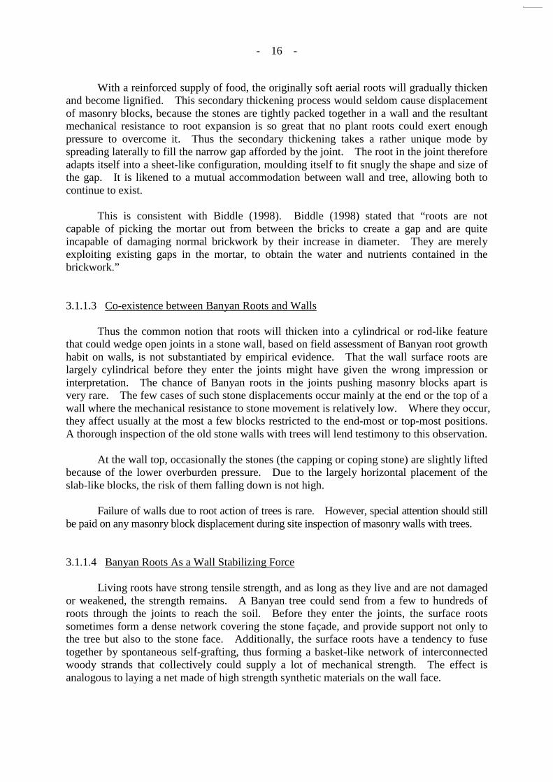
With a reinforced supply of food, the originally soft aerial roots will gradually thicken and become lignified. This secondary thickening process would seldom cause displacement of masonry blocks, because the stones are tightly packed together in a wall and the resultant mechanical resistance to root expansion is so great that no plant roots could exert enough pressure to overcome it. Thus the secondary thickening takes a rather unique mode by spreading laterally to fill the narrow gap afforded by the joint. The root in the joint therefore adapts itself into a sheet-like configuration, moulding itself to fit snugly the shape and size of the gap. It is likened to a mutual accommodation between wall and tree, allowing both to continue to exist. This is consistent with Biddle (1998). Biddle (1998) stated that “roots are not capable of picking the mortar out from between the bricks to create a gap and are quite incapable of damaging normal brickwork by their increase in diameter. They are merely exploiting existing gaps in the mortar, to obtain the water and nutrients contained in the brickwork.” 3.1.1.3 Co-existence between Banyan Roots and Walls Thus the common notion that roots will thicken into a cylindrical or rod-like feature that could wedge open joints in a stone wall, based on field assessment of Banyan root growth habit on walls, is not substantiated by empirical evidence. That the wall surface roots are largely cylindrical before they enter the joints might have given the wrong impression or interpretation. The chance of Banyan roots in the joints pushing masonry blocks apart is very rare. The few cases of such stone displacements occur mainly at the end or the top of a wall where the mechanical resistance to stone movement is relatively low. Where they occur, they affect usually at the most a few blocks restricted to the end-most or top-most positions. A thorough inspection of the old stone walls with trees will lend testimony to this observation. At the wall top, occasionally the stones (the capping or coping stone) are slightly lifted because of the lower overburden pressure. Due to the largely horizontal placement of the slab-like blocks, the risk of them falling down is not high. Failure of walls due to root action of trees is rare. However, special attention should still be paid on any masonry block displacement during site inspection of masonry walls with trees. 3.1.1.4 Banyan Roots As a Wall Stabilizing Force Living roots have strong tensile strength, and as long as they live and are not damaged or weakened, the strength remains. A Banyan tree could send from a few to hundreds of roots through the joints to reach the soil. Before they enter the joints, the surface roots sometimes form a dense network covering the stone façade, and provide support not only to the tree but also to the stone face. Additionally, the surface roots have a tendency to fuse together by spontaneous self-grafting, thus forming a basket-like network of interconnected woody strands that collectively could supply a lot of mechanical strength. The effect is analogous to laying a net made of high strength synthetic materials on the wall face.

- 17 -
Figure 3 - The Surface Roots of Chinese Banyan Form a Dense Network Covering the Stone Façade at Hospital Road
3.1.2 Effect of Tree Roots on Soil behind Retaining Walls In order to review the effect of tree roots on soil behind retaining walls and the method of quantifying the effect, a literature review was carried out. 3.1.2.1 Root Strengthening Tree roots can strengthen soil. In masonry walls with trees, the roots of wall trees that penetrate the joints would move into the soil situated behind the stones, and there they will ramify and anchor the tree. Therefore, the soil behind tree walls is likely to be strengthened by tree roots. This is consistent with Chan (1996) and Lee (1985). Chan (1996) thought that “if the tree root system penetrates a wall into the retained soil, it will reinforce the soil locally and increase the friction between the soil and the wall. This reinforcement effect should be more prominent for dense soils. Again, the amount of this effect is not known and it is unlikely that it can be found analytically.” Lee (1985) stated that “the root system of vegetation also serves the function of slope stabilisation by providing reinforcement and additional resistance to the soil mass.” 3.1.2.2 Tree Root Decay Decay of tree roots will create voids in soil. However, all soils contain porosity to

- 18 -
permit the transfer of air and water and for the storage of moisture, a part of which is available to plant growth. Some porosity is due to natural grain packing, some to natural soil structural formation, and some to biological activities such as the channels left by burrowing worms or after the death of roots. The smaller roots grow and die continually, and the pores formed after the decay of such roots are small and can be considered a part of natural soil forming processes. They do not concentrate subsurface water flows and will not threaten wall stability. Decay of larger roots may increase the permeability of soil and the stability of soil behind masonry walls may be affected. Most trees will keep most of the larger roots, just like they will keep most of the branches. However, being living creatures, some branches and some large roots will occasionally die usually due to the invasion of wood-decay fungus or to diseases induced by other pathogenic organisms. Special attention should be paid on decay of large tree roots to ascertain that the strength of soil is not affected. 3.1.2.3 Quantifying Root Strengthening Effect Based on literature review, the following simplified equation was found in Gray & Sotir (1995), Greenway (1987) and Lee (1985) for determining the effect of root reinforcement and strength on soil.
Δs =1.2TR (AR/A) where Δs is the shear strength increase TR is the tensile strength of root AR/A is the root area ratio Based on Gray & Sotir (1995), this model assumes that the roots are well anchored and do not pull out under tension. The root fibers must be long enough and/or subjected to sufficient interface friction for this assumption to be satisfied. Greenway (1987) also reported that the tensile strength of root for Chinese Banyan was 16 MPa. 3.1.3 Relevant Wall Failures
3.1.3.1 Search for Relevant Wall Failures In order to review the effects of tree roots on the stability of masonry walls, wall failures that are possibly related to wall trees were collected from the following sources and assessed:
(i) a list provided by LPM Division 1, Geotechnical Engineering Office (GEO);
(ii) records from Leisure and Cultural Services Department
(LCSD); (iii) records from Agriculture, Fisheries & Conservation
Department (AFCD);

- 19 -
(iv) record provided by GEO in a meeting; (v) Chan (1996) - GEO Report No. 31; and (vi) newspapers.
A list provided by LPM Division 1, Geotechnical Engineering Office (GEO) A list of features in Central and Western District and Wan Chai District were received from LPM Division 1, GEO in Nov 2004. There were totally 2642 features in the list. These features are all retaining walls (CR, FR and R types) of masonry or unknown wall types. Out of these 2642 features, there were 55 features with landslide incident reports and two of them had past instability related to trees. Records from Leisure and Cultural Services Department (LCSD) Letters were sent to 18 Districts of LCSD in Dec 2004 and Jan 2005 to retrieve records of cases involving tree collapse on masonry walls. 13 Districts replied and only two Districts had records. A summary table showing the replies from LCSD is included in Appendix B, Page B1. Records from Agriculture, Fisheries & Conservation Department (AFCD) A Letter was sent to AFCD in Dec 2004 to retrieve records of cases involving tree collapse on masonry walls. No records of tree collapse on masonry walls were under the maintenance responsibility of AFCD. Record provided by GEO in a meeting A case related to tree was provided by GEO in a meeting for this special task on 14 Dec 2004. Chan (1996) - GEO Report No. 31 Chan (1996) studied 10 case histories of instability of masonry retaining walls in Hong Kong. None of them were related to trees. Newspapers A wall tree failure was reported on 9 Aug 2005 at 67 Wyndham Street, Central.

- 20 -
Table 2 - Summary of Landslide Incident Records Related to Trees
Feature No. Location Incident No.
(Date of Incident) Type of Failure Scale
Possible Contributing Causes of Failure
Source of Information
11SW-A/FR24 Behind Hillview
Garden, Hill Road, Pokfulam
HK97/5/2 (09/05/1997)
Non landslip case (tree fall and
masonry blocks fall)
Two masonry blocks
involved Tree fall LPM1/GEO
11SW-A/R120 Ka Wai Man Road
Garden
- (9/2003)
- - -
LCSD HK99/8/3
(22/08/1999)
Non landslip case (tree uprooted with
6 m x 4 m x 1 m soil mass on slope)
24 m3 Tree uprooted under
typhoon
11SW-A/R751
South of 450-456, Queen’s Road
West, Hong Kong
HK1999/8/4 (23/08/1999)
Retaining wall hit by fallen tree which
grew above the wall N/A N/A LPM1/GEO
Clarence Terrace Children’s Playground
- (06/2003)
- - - LCSD
11SE-A/C897 (old no.
11SE-A/R51)
Front of Lai Sing Court, Tai Hang Road, Tai Hang
HK2003/9/0180 (04/09/2003)
Tree fall and adjacent stone
pitching blocks on wall pulled down
1 m3 volume of slip scar
Tree uprooted by strong wind pull down
the adjacent stone pitching block near
the crest of wall
Meeting on 14 Dec 04
11NW-B/C321 Lei Cheng Uk
Swimming Pool -
(09/2004) - - - LCSD
11SW-B/R735 Behind and below 61-67 Wyndham Street, Central
- (09/08/2005)
- - - Newspapers

- 21 -
- 21 -
3.1.3.2 Records of Relevant Wall Failures From the records collected, the following five features were found to have wall failures related to trees:
(i) Feature No. 11SW-A/FR24; (ii) Feature No. 11SW-A/R120; (iii) Feature No. 11SW-A/R751; (iv) Feature No. 11SE-A/C897 (old no. 11SE-A/R51); and (v) Feature No. 11NW-B/C321.
The details of the above features were summarized in Table 2. The basic information and detailed information, photographs, plans, SIFT report and landslide incident reports were included in Appendix B. Feature No. 11SW-A/FR24 Based on the landslide incident report (HK97/5/2), Feature No. 11SW-A/FR24 was a dry-packed random rubble wall. A tree was located on the wall face near the crest of the feature. The incident recorded was a non landslip case. (See Appendix B, Pages B2-B12) A tree fell down and caused localized damage to the masonry wall (two masonry blocks fell down). No signs of past instability could be found on the feature during the site inspection carried out in Nov 2004.
Figure 4 - Feature No. 11SW-A/FR24

- 22 -
- 22 -
Feature No. 11SW-A/R120 Photographs about the incident in Ka Wai Man Road Garden on Sep 2003 were received from LCSD. (See Appendix B, Pages B13-B29) From site inspection in Feb 2005, the fallen tree was located at Feature No. 11SW-A/R120. Minor repair works were noted on the wall. The joints between masonry blocks at the location of the fallen tree were repaired by cement mortar.
Figure 5 - Feature No. 11SW-A/R120
Figure 6 - Joints between Masonry Blocks at the Location of Fallen Tree were Repaired An incident report (HK99/8/3) was found in GEO on this feature. However, the incident happened in 1999, but not 2003. The incident report indicated that the failure in 1999 involved failure in soil cut slope portion only and the fallen tree was located at the crest of a slope.

- 23 -
As the photographs from LCSD did not indicate any wall failure and no landslide incident report of the wall were found in GEO about this incident, it appears that the wall was not failed. Small blocks might have fallen down or only cracks appeared in the pointing. Feature No. 11SW-A/R751 Based on the landslide incident report (HK1999/8/4) of Feature No. 11SW-A/R751, the incident recorded involved a fallen tree only. (See Appendix B, Pages B30-B38) The masonry retaining wall was not failed. Although trees were found on the wall face of the feature, the incident report indicated that the tree fallen was located behind the crest of the feature. Therefore, this incident did not involve any wall trees. No signs of past instability could be found on the feature during the site inspection carried out in Nov 2004 and Feb 2005. Photographs about the incident in Clarence Terrace Children’s Playground were received from LCSD. (See Appendix B, Pages B39-B40) From the photos and site inspection carried on Feb 2005, the fallen tree was likely to be located at the children’s playground behind the crest of Feature No. 11SW-A/R751, not on the wall. No incident records in 1999 at Feature No. 11SW-A/R751 could be found in GEO. As the photographs did not indicate any wall failure and no landslide incident report of the wall were found in GEO, it appears that this incident involved fallen tree only. The masonry wall did not fail.
Figure 7 - Feature No. 11SW-A/R751
Figure 8 - Crest of Feature No. 11SW-A/R751 Feature No. 11SE-A/C897 (old no. 11SE-A/R51) Based on the landslide incident report (HK2003/9/0180) of Feature No. 11SE-A/C897, stone pitching blocks near the crest of wall were pulled down by a tree uprooted by strong wind. However, the tree causing the failure was located behind the crest of the feature (See Appendix B, Pages B41-B50) and the feature was a cut slope, not a retaining wall. The

- 24 -
stone pitching blocks were a facing only. Therefore, this incident did not involve any wall trees and wall failures. The stone blocks were pulled down by a tree uprooted by strong wind not associated with the growth of the tree roots.
Figure 9 - Photo Extracted from Landslide Incident Report (HK2003/9/0180)
Figure 10 - Photo Extracted from Landslide Incident Report (HK2003/9/0180) Feature No. 11NW-B/C321 Based on LCSD’s records, a tree fell from a cut slope Feature No. 11NW-B/C321, but it was not a retaining wall. (See Appendix B, Pages B51-B60) The incident involved a fallen tree only and did not involve any wall trees and wall failures. Feature No. 11SW-B/R735 Based on the newspapers, a wall tree on Feature No. 11SW-B/R735 failed on 9 Aug 2005. Site inspection was carried out on 10 Aug 2005. The masonry wall was not damaged.

- 25 -
The incidents in Feature Nos. 11SW-A/FR24 and 11SW-A/R120, although involved or might involve falling down of masonry blocks caused by wall trees, the failures were localized and the scales were small. They were caused by failure of a tree due to its own weight or wind load, not related to the growth of tree roots. The failure of the wall tree on Feature No. 11SW-B/R735 did not cause any wall failure. The trees that failed near Feature No. 11SW-A/R751 were not actually wall trees per se. The incidents in Feature Nos. 11SE-A/C897 and 11NW-B/C321 did not involve masonry walls and thus are not related to this study. Based on the above past instability records, there is no direct evidence to show that the roots of wall trees resulted in instability of masonry walls. 3.1.4 Recommendations Based on the above studies, tree roots seldom cause displacement of masonry blocks. The few cases of such stone displacements occur mainly at the end or the top of a masonry wall. The tree roots may even strengthen the wall face by forming a dense network on it. However, attention should still be paid to masonry block displacement, if any, during inspections to ascertain that such displacement is not due to tree roots. The soil behind masonry walls is likely to be strengthened by tree roots. However, attention should still be paid to possible decay of large tree roots, if any, during inspections to ascertain that the strength of the soil vulnerability to water ingress is not adversely affected. A simplified equation, presented in Section 3.1.2.3, was found for quantifying the root strengthening effect. However, it is difficult to determine the root area ratio, the extent of tree roots and thus the extent of soil that might be strengthened. The root strengthening effect may also vary greatly from place to place. As the potential beneficial effects of the tree roots on the stability of masonry walls are difficult to quantify in a reliable manner, these beneficial effects may be conservatively ignored during stability analysis of masonry walls with trees. 3.2 Effects of Tree Stem The effects of aboveground portion of wall trees are further classified into the following aspects:
(i) surcharge of trees on masonry walls; and (ii) wind effect on wall trees and thus on masonry walls.
The details are discussed in Section 3.2.1 and 3.2.2.
Figure 11 - Tree failure on Feature No. 11SW-B/R735

- 26 -
Final Tree Dimensions As trees are living beings, they will grow up until reaching the final dimensions. Therefore, instead of the current tree dimensions, the estimated final dimensions should be used during the stability of the wall analysis. Different individual trees have different genetic constitution (the genotype) that could determine its biological potential dimensions (BPD). However, not every tree could attain its BPD. For trees growing normally on the ground, various abiotic and biotic factors interacting with or impinging on a tree will reduce the final dimensions that could be reached. This is generally known as phenotypic plasticity which is very much a function of the multivariate and changeable tree-environment interactions. In other words, the phenotype can only express itself within the boundaries circumscribed by the genotype. Trees living on stone walls are subject to a lot more stresses than ground-growing ones, and hence they normally may not be able to attain their BPD. The amount of discount will be estimated by assessing the opportunities or stresses to tree growth on individual walls, and by evaluating the vigour of the trees in question. In order to estimate the final dimension of each wall tree, site inspection by a tree expert should be carried out. The final dimension should be based on the expert judgment by evaluating selected ecological information of the wall tree on its past growth regime and its associated wall conditions in detail. 3.2.1 Surcharge of Trees on Masonry Walls Aboveground biomass of wall trees furnishes additional surcharges on masonry walls. Since all wall trees are located on the front face of the walls, it causes additional overturning moments to act on the walls.
Tree
Soil
Masonry Wall
Aboveground biomass of wall tree causes additional overturning moments
- 27 -
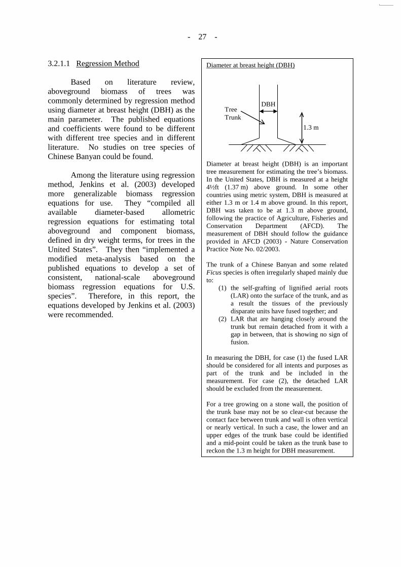
3.2.1.1 Regression Method Based on literature review, aboveground biomass of trees was commonly determined by regression method using diameter at breast height (DBH) as the main parameter. The published equations and coefficients were found to be different with different tree species and in different literature. No studies on tree species of Chinese Banyan could be found. Among the literature using regression method, Jenkins et al. (2003) developed more generalizable biomass regression equations for use. They “compiled all available diameter-based allometric regression equations for estimating total aboveground and component biomass, defined in dry weight terms, for trees in the United States”. They then “implemented a modified meta-analysis based on the published equations to develop a set of consistent, national-scale aboveground biomass regression equations for U.S. species”. Therefore, in this report, the equations developed by Jenkins et al. (2003) were recommended.
Diameter at breast height (DBH)
Diameter at breast height (DBH) is an important tree measurement for estimating the tree’s biomass. In the United States, DBH is measured at a height 4½ft (1.37 m) above ground. In some other countries using metric system, DBH is measured at either 1.3 m or 1.4 m above ground. In this report, DBH was taken to be at 1.3 m above ground, following the practice of Agriculture, Fisheries and Conservation Department (AFCD). The measurement of DBH should follow the guidance provided in AFCD (2003) - Nature Conservation Practice Note No. 02/2003. The trunk of a Chinese Banyan and some related Ficus species is often irregularly shaped mainly due to:
(1) the self-grafting of lignified aerial roots (LAR) onto the surface of the trunk, and as a result the tissues of the previously disparate units have fused together; and
(2) LAR that are hanging closely around the trunk but remain detached from it with a gap in between, that is showing no sign of fusion.
In measuring the DBH, for case (1) the fused LAR should be considered for all intents and purposes as part of the trunk and be included in the measurement. For case (2), the detached LAR should be excluded from the measurement. For a tree growing on a stone wall, the position of the trunk base may not be so clear-cut because the contact face between trunk and wall is often vertical or nearly vertical. In such a case, the lower and an upper edges of the trunk base could be identified and a mid-point could be taken as the trunk base to reckon the 1.3 m height for DBH measurement.
1.3 m
DBH Tree Trunk
- 28 -
- 28 -
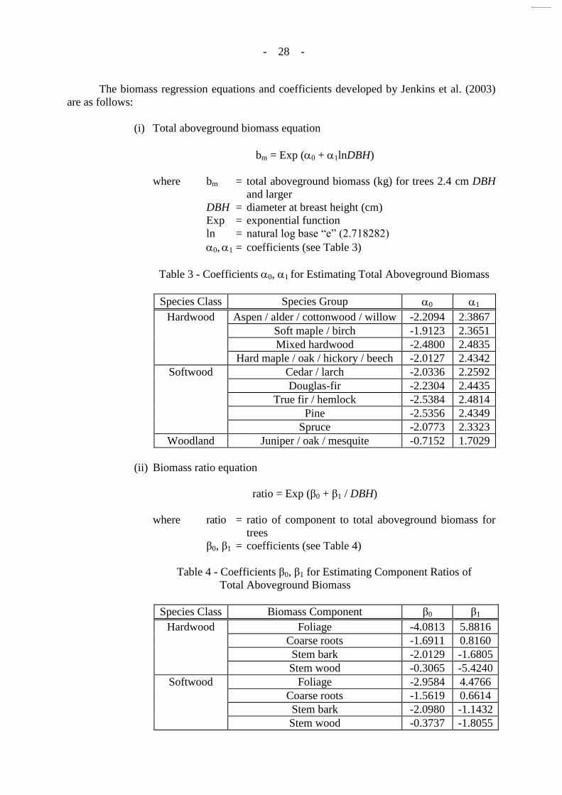
The biomass regression equations and coefficients developed by Jenkins et al. (2003) are as follows:
(i) Total aboveground biomass equation
bm = Exp (0 + 1lnDBH)
where bm = total aboveground biomass (kg) for trees 2.4 cm DBH and larger
DBH = diameter at breast height (cm) Exp = exponential function ln = natural log base “e” (2.718282) 0, 1 = coefficients (see Table 3)
Table 3 - Coefficients 0, 1 for Estimating Total Aboveground Biomass
Species Class Species Group 0 1
Hardwood Aspen / alder / cottonwood / willow -2.2094 2.3867 Soft maple / birch -1.9123 2.3651 Mixed hardwood -2.4800 2.4835
Hard maple / oak / hickory / beech -2.0127 2.4342 Softwood Cedar / larch -2.0336 2.2592
Douglas-fir -2.2304 2.4435 True fir / hemlock -2.5384 2.4814
Pine -2.5356 2.4349 Spruce -2.0773 2.3323
Woodland Juniper / oak / mesquite -0.7152 1.7029
(ii) Biomass ratio equation
ratio = Exp (β0 + β1 / DBH)
where ratio = ratio of component to total aboveground biomass for trees
β0, β1 = coefficients (see Table 4)
Table 4 - Coefficients β0, β1 for Estimating Component Ratios of Total Aboveground Biomass
Species Class Biomass Component β0 β1
Hardwood Foliage -4.0813 5.8816 Coarse roots -1.6911 0.8160 Stem bark -2.0129 -1.6805 Stem wood -0.3065 -5.4240
Softwood Foliage -2.9584 4.4766 Coarse roots -1.5619 0.6614 Stem bark -2.0980 -1.1432 Stem wood -0.3737 -1.8055

- 29 -
- 29 -
Branch biomass can be obtained by subtracting total above ground biomass by other components (foliage, stem bark and stem wood). The Chinese name of the species group is included in Appendix C, Page C1. 3.2.1.2 Species Group Adopted The equations published by Jenkins et al. (2003) were developed for U.S. species and these species are temperate latitude tree species. However, wall trees in Hong Kong are tropical tree species. They do not belong to any species groups in Table 3. In order to use the equations published by Jenkins et al. (2003), a suitable species group should be chosen. Species Group Based on Chinese Banyan Surcharge of trees on masonry walls depends on its aboveground biomass. Trunk and branches (the woody parts) rather than foliage are the principal contributor of aboveground biomass of trees. Among the 30 tree species found on masonry walls in Hong Kong, the Ficus species and Celtis sinensis species tend to develop heavy trunk and branches. For the same diameter at breast height (DBH), tree height and crown spread, they should have similar weight. As discussed in Section 2.2, Chinese Banyan is the dominant wall tree species in Hong Kong. Therefore, the aboveground biomass of wall trees is determined based on Chinese Banyan trees. Chinese Banyan Chinese Banyan is an evergreen broadleaf tree with a decurrent tree architecture, meaning that it has no clear central leader and the main (scaffold) branches are quite thick and they tend to be more or less similar in diameter to share the co-dominance. Branches tend to bifurcate at many levels until they reach the smallest twigs at the outer rim of the crown. The leaves are flat blades which have a relatively higher specific surface area and higher wind resistance than conifer needle-shaped leaves. The overall tree form of a Banyan is a broad crown with a rounded top with dense foliage. Species Group Adopted Based on the above characteristics, to estimate the surcharge of a Chinese Banyan tree, the best choice is “hard maple / oak / hickory /beech” under Hardwood category although equations adopted for tropical trees may over-estimate the bark weight in tropical trees. Moreover, among the species group in Jenkins et at. (2003), “hard maple / oak / hickory /beech”, the total aboveground biomass of “Hard maple/oak/hickory/beech” is
Twig A twig is the smallest division of a branch, usually composed of rather new branches of the current or preceding year.

- 30 -
- 30 -
generally the largest (See Appendix C, Page C2). Therefore, the species group of “hard maple / oak / hickory /beech” was recommended. 3.2.1.3 Moisture in Wall Trees Biomass of trees with moisture should be considered during stability analysis. However, the regression equation recommended in Section 3.2.1.1 estimates total aboveground and component biomass, defined in dry weight terms. Therefore weight of water should further be allowed for. The weight of water in living trees can vary according to species, tree age, tree size, tree health, soil moisture, wind speed, air temperature, relative humidity and stomatal conductance. Therefore, literature review has been conducted on the moisture content of trees. The amount of wood moisture varies by the position above the ground, with a tendency to have more moisture in the heartwood at the base of the trunk and a gradual decrease with height. Therefore, an average value of 50% of the dry weight of the wood is recommended to denote the water content in living trees during the stability analysis. 3.2.1.4 Recommendation The equations developed by Jenkins et al. (2003) may over-estimate the bark weight in determining aboveground biomass of Chinese Banyan. However, these equations were comparatively more consistent and national-scale and no publications could be found for Chinese Banyan. Therefore, in this report, the equations developed by Jenkins et al. (2003) were recommended to determine the dry weight of wall trees and the species group of “hard maple / oak / hickory /beech” was recommended. The surcharge of the tree trunk should be increased by 50% to allow for the moisture content of wall trees. 3.2.2 The Wind Effect on Trees and Thus on Masonry Walls Wind forces on wall trees may cause additional sliding forces and overturning moments to act on the masonry walls. As a wall tree is not a temporary structure, according to Building (Construction) Regulations, the wind load shall be based on the velocity and gust effect of winds from any direction suitably determined from a return period of not less than 50 years.
Moisture content Moisture content of wood is defined as the weight of water in wood expressed as a fraction, usually a percentage, of the weight of oven-dry wood. Stomatal conductance Stomatal conductance is the rate of passage of water vapour and air through the stomata which are tiny pores on leaf surfaces. Heartwood As a tree increases in age and diameter, an inner portion of the sapwood becomes inactive and finally ceases to function, as the cells die. This inert or dead portion is called heartwood. Sapwood Sapwood is comparatively new wood, comprising living cells in the growing tree, situated in the outer part of a trunk or branch. All wood in a tree is first formed as sapwood.

- 31 -
- 31 -
When the tree stem and anchorage between the tree roots and the masonry wall are strong enough to resist stem failure and uprooting, the wind load acting on wall trees will be transmitted to the masonry wall and cause additional sliding forces and overturning moments. Details of calculation of wind loading on masonry walls are included in Sections 3.2.2.3 to 3.2.2.7. However, wall trees, which are different to buildings or structures, grow naturally and are not designed to provide supports. Wall trees may therefore fail before sustaining a significant wind pressure. Therefore, whether wind load should be checked or not will principally depend on the resistive bending moment of the tree that can be developed at failure. There are two potential modes of failure for wall tree: stem failure and uprooting. Uprooting is more prevalent in tree failures. If the root anchorage is strong enough to prevent a tree from uprooting, the force will be transferred to the tree stem and could result in stem breakage. Details of stem failure and uprooting are included in Sections 3.2.2.1 and 3.2.2.2. 3.2.2.1 Stem Failure Maximum resistive bending moment of tree Based on Moore (2000) and Peltola et al. (2000), the theoretical maximum resistive bending moment for stem failure can be calculated as follows:
Tree
Soil
Masonry Wall
Wind forces on wall trees may cause additional sliding forces and overturning moments to act on the masonry wall

- 32 -
- 32 -
Height and Crown Spread of Chinese Banyan According to Jim (1988), Chinese Banyan trees growing healthily on the ground “can reach a final dimension of 30m height, and a rounded-spreading crown 11⁄2 times wider than tall in uncluttered environments.” On a stone retaining wall, the biological potential dimensions (BPD, see Section 3.2) cannot be attained. Based on empirical assessment, the maximum height of Chinese Banyan on wall is 20 m.
BMT = π x MOR x DBH3 / 32
where BMT = theoretical maximum resistive bending moment (MNm) MOR = modulus of rupture of tree stem (MPa) DBH = diameter at breast height (m) Based on Lei et al. (2005) and Wang et al. (2005), the modulus of rupture (MOR) for the tested black spruce and young Taiwania trees ranges from 29.33 MPa to 65.48 MPa. As the modulus of rupture of tree stem varies greatly for different trees, a literature review was carried out on the wind speed for stem failure and compared with the design wind speed. Wind speed for tree failure Johnson et al. (1982) summarized the calculated and recorded wind speeds at stem failure of several loblolly pines in the area of Mobile County, Alabama. From the table, the failure wind speeds ranged from 75 to 129 mph with diameter of tree bole ranging from 0.8 to 1.1 feet, i.e. the failure wind speeds ranged from 34 m/s to 58 m/s with diameter of tree bole ranging from 0.24 m to 0.34 m (1 mph = 1.61 km/h, 1 ft = 0.305 m). Design wind speed A wall tree generally cannot reach a final dimension of 30 m high. Therefore, only the design wind speed of height up to 30 m above site-ground level are considered in this report. Based on BD (2004b) (hereinafter referred to as “Explanatory Material to The Wind Code”), the corresponding gust velocities for trees with heights ranging from 5 m - 30 m are summarized in the following table:
Table 5 - Design Wind Speed
Tree Height Design Wind Speed (m/s)
5 m 55.1
10 m 57.9
20 m 61.0
30 m 62.8
- 33 -
- 33 -
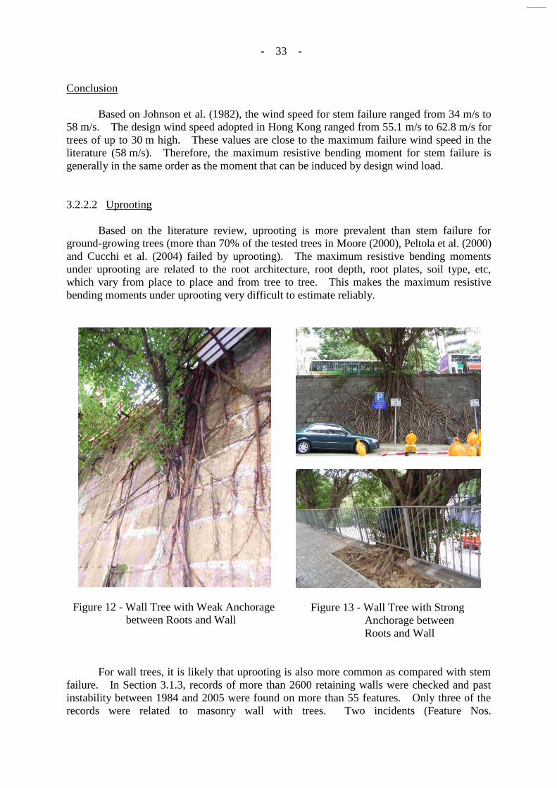
Conclusion Based on Johnson et al. (1982), the wind speed for stem failure ranged from 34 m/s to 58 m/s. The design wind speed adopted in Hong Kong ranged from 55.1 m/s to 62.8 m/s for trees of up to 30 m high. These values are close to the maximum failure wind speed in the literature (58 m/s). Therefore, the maximum resistive bending moment for stem failure is generally in the same order as the moment that can be induced by design wind load. 3.2.2.2 Uprooting Based on the literature review, uprooting is more prevalent than stem failure for ground-growing trees (more than 70% of the tested trees in Moore (2000), Peltola et al. (2000) and Cucchi et al. (2004) failed by uprooting). The maximum resistive bending moments under uprooting are related to the root architecture, root depth, root plates, soil type, etc, which vary from place to place and from tree to tree. This makes the maximum resistive bending moments under uprooting very difficult to estimate reliably.
Figure 12 - Wall Tree with Weak Anchorage between Roots and Wall
Figure 13 - Wall Tree with Strong Anchorage between Roots and Wall
For wall trees, it is likely that uprooting is also more common as compared with stem failure. In Section 3.1.3, records of more than 2600 retaining walls were checked and past instability between 1984 and 2005 were found on more than 55 features. Only three of the records were related to masonry wall with trees. Two incidents (Feature Nos.

- 34 -
- 34 -
11SW A/FR24 and 11SW-A/R120) involved or might have involved localized failures of masonry blocks caused by wall tree failures. The third incident (Feature No. 11SW-B/R735) involved failure of a wall tree only and the masonry wall itself was not damaged. In these three incidents, all the wall trees failed probably at the root anchorage and caused little or no damage to the walls. Therefore, in these three cases, the maximum resistive bending moments under uprooting limited the wind load that could be transmitted to the walls. Conclusion Uprooting may be more common than stem failure in wall tree failure for commonly encountered wall trees in Hong Kong. However, owing to the limited number of records (only three incidents related to masonry walls with trees), it cannot be concluded that all wall trees will fail in uprooting before transferring significant wind load to the wall. If the root anchorage is strong enough to prevent uprooting, the wind load will be transferred to the stems and the walls. In the assessment of the stability of masonry walls with trees, professional judgement should be exercised regarding whether the root anchorage is strong enough to sustain the design wind forces. If not, the wind forces on wall trees could be ignored as far as the consequential effect on masonry walls is concerned. 3.2.2.3 Static Effect Based on literature review, classical formula was commonly used to determine wind load induced on a tree (Mayhead (1973); Johnson et al. (1982); Stathers et al. (1994); Spatz & Bruechert (2000); Rudnicki et al. (2004)). Therefore, the classical formula was adopted in this report. Using the classical formula, the wind force in the direction of wind flow on an object placed in a steady airstream is calculated as: F = 1/2 ρ CD AV2 = CD A qz ................................................................. eq.1 where F = the wind force (newtons, N) ρ = the density of air (kg/m3) CD = the drag coefficient (dimensionless) A = the frontal area (m2) V = the wind velocity (m/s) qZ = basic wind pressure at height z (N/m2) = (1/2ρV2) Discussion on basic wind pressure (qZ), drag coefficient (CD) and frontal area (A) is provided in Sections 3.2.2.1, 3.2.2.2 and 3.2.2.3 respectively. 3.2.2.4 Basic Wind Pressure The pressures extracted from BD (2004a), (hereinafter referred to as “Wind Code”) are listed in the following table:

- 35 -
Table 6 - Design Wind Pressure Extracted from the Wind Code
Height above Site-ground Level Design Wind Pressure (kPa)
≤ 5 m 1.82
10 m 2.01
20 m 2.23
30 m 2.37 For assessing wind loads on trees, the site-ground level should be taken as the level at which the most adverse effect would be caused to the stability of the wall. Where topography is considered significant, topography factor should be determined based on the Wind Code. 3.2.2.5 Drag Coefficient In order to determine the drag coefficient, a literature review was carried out. Based on the literature review, the drag coefficients have been found to depend on the porosity of tree crown, degree of permeability for air movements and flexibility of tree crown and these parameters vary considerably between tree species. Drag coefficients used in some literature were summarized. In order to determine the suitable drag coefficients for wall trees in Hong Kong, testing wind speed and tree species used in literature were studied. Porosity and Permeability of Tree Crown Porosity and permeability of tree crown would affect the drag coefficient. Spatz & Bruechert (2000) stated that “since the secondary branches never fully overlap and the actual silhouette is not that of a solid cone, some degree of permeability of the crown for air movements has to be taken into account” for the drag coefficient. Flexibility of Tree Crown Based on the following literature, the drag coefficient was found to decrease when wind speed increases. As tree crowns are flexible, they tend to bend and become more streamlined when wind speed increases. The frontal area will thus decrease. As a fixed frontal area is assumed in calculating critical wind speeds, the drag coefficient will thus decrease to take into account of streamlining effect. However, the rate of reduction in drag coefficient is low for high wind speeds. Johnson et al. (1982) stated that “Result of Mayhead’s 1973 research ‘indicated a reduction of the drag coefficient with increased windspeed and a large variation in drag coefficients both between and within a species’ ”.

- 36 -
- 36 -
Rudnicki et al. (2004) stated that “As wind force increases, branches and foliage move into alignment with the wind direction, reducing the crown frontal area (streamlining) and therefore the pressure component of drag. Thus, streamlining depends on the mechanical and aerodynamic properties of stems, branches, and foliage. A number of authors have used eq.1 for calculating critical wind speeds assuming a fixed frontal area, …” and “with the assumption that 26 m/s is close to the critical wind speed for tree failure and that the rate of reduction in drag coefficient with increasing wind speed is low for wind speeds above 26 m/s”. Stathers et al. (1994) stated that when “wind speed increases, the canopy tends to bend and deflect and become more streamlined”. Tree Trunk Based on the following literature, tree trunks, different from crowns, are not porous and relatively not flexible. Therefore, no reduction in drag is considered and the drag coefficient is assumed to approximate those of a smooth cylinder (1.2). Johnson et al. (1982) stated that “Wind pressure coefficients for the bole will be assumed to approximate those of a thin smooth cylinder (1.2) even though the bark roughness and high windspeeds would both increase these coefficients (Note, wind forces on the bole are minor relative to those on the canopy).” Spatz & Bruechert (2000) stated that “Calculating the wind loads on the trunk followed essentially the same route except that the reduction of drag due to the flexibility of the top parts of the crown were found small and were therefore not explicitly taken into account”. Drag Coefficient from Literature Review A number of researchers have conducted studies on tree drag. The following tables summarized drag coefficient of tree trunk and tree crown in literature:
Table 7 - Drag Coefficient of Trunk Suggested in Literature
Literature CD
Sun et al. (2003) 1.2
Johnson et al. (1982) 1.2

- 37 -
- 37 -
Table 8 - Drag Coefficient of Tree Crown Obtained from Wind Tunnel Test in Literature
Literature Tree Species Wind Speed CD
Johnson et al. (1982) Dwarf white pines (松) (dwarf conifers)
(assumed for high solidities)
High 0.5 (average)
Cryptomeria (杉) (dwarf conifers)
(assumed for low solidities)
High 0.3
Mayhead (1973) Lodgepole pine (松) 30 m/s 0.20
Western hemlock (鐵杉) 30 m/s 0.14
Lodgepole pine (松) 26 m/s 0.35
Rudnicki et al. (2004) Redcedar (紅側柏) 20 m/s 0.22
Lodgepole pine (松) 20 m/s 0.47
Hemlock (鐵杉) 20 m/s 0.471
Spatz & Bruechert (2000) Norway spruce tree (雲杉) Very low 0.52
Stathers et al. (1994) Engelmann spruce (雲杉) & subalpine fir (冷杉)
(stiff branches and needles)
25 m/s 0.5
10 m/s 0.8
Lodgepole pine (松) & Douglas-fir (冷杉)
(more flexible branches)
25 m/s 0.3
10 m/s 0.6
Western hemlock (鐵杉) (very spindly branches and crowns)
25 m/s 0.2
10 m/s 0.3
Notes: (1) 1 0.4 was recommended in the literature. (2) 2 recommended value only, not from wind tunnel test.
Drag coefficients for tree crown showed in Table 8 were obtained from wind tunnel tests using artificial trees or real trees as the testing samples. Therefore, the porosity of tree crowns, degree of permeability of the crown for air movements has been already taken into account in determining drag coefficient. Testing Wind Speed Based on the literature review, the rate of reduction in drag coefficient is low for high wind speeds and the design wind speed during analysis is close to the wind speed for tree failure, the drag coefficient at high wind speed should be considered. Based on critical wind speed (26 m/s) mentioned by Rudnicki et al. (2004), only those drag coefficients in Table 8 with testing wind speed above 26 m/s were considered and the maximum value was found to be 0.5.

- 38 -
- 38 -
Tree Species All the testing samples in the above literature were conifers. However, the wall tree species found in Hong Kong are not conifers (See Section 2.1.1). As wind load on wall trees partially depends on the density of tree crown. Leaf area index (LAI), a measurement for plant density and growth, was compared to review the drag coefficient. Among the 30 wall tree species in Hong Kong, Ficus microcarpa (Chinese Banyan) has the highest leaf area index (LAI), although several species have values close to it, such as Ficus superba (Superb Fig) and Celtis sinensis (Chinese Hackberry). The dominant wall tree species, Chinese Banyan, is therefore taken as the maximum-value scenario in the calculation of wind load. Drag coefficient of wall trees is thus based on Chinese Banyan trees. A healthy conifer tree may have an average LAI of around 5:1. The LAI for the optimal case of Chinese Banyan is 8:1. However, this value is for trees growing healthily on the ground, with little obstacle to the spread of its roots and crown. In this report, the trees studied are growing on stone retaining walls. The highly restrictive environment for root penetration and extension, and the stresses on stem (trunk, branches, foliage) development, would curtail growth quite substantially. The LAI could be reduced to about 5:1 for trees on the least stressful wall sites. On the most stressful sites it could be suppressed further. Therefore LAI for wall trees in Hong Kong is similar to that of the species tested. Recommendation For tree trunk, as only 1.2 was suggested in the reviewed literature, a drag coefficient of 1.2 is recommended for the tree trunk. Since no study on the drag coefficient of Chinese Banyan could be found and the LAI is similar for the species in Table 8 and Chinese Banyan trees growing on masonry walls, a drag coefficient of 0.5 is recommended for the tree crown. 3.2.2.6 Frontal Area The frontal area of tree crown is usually difficult to be determined on site. For simplicity, the frontal area of crown for wall trees in Hong Kong may be assumed to be elliptical in shape.
Leaf area index (LAI) Leaf area index (LAI) is the total of single-side leaf surface area in relation to the projection of the crown area onto the ground. It is a measurement of foliage density and growth.

- 39 -
- 39 -
Figure 14 - Frontal Area of the Crown of Wall Trees in Hong Kong is Similar to an Ellipse
3.2.2.7 Dynamic Effects The dynamic effects due to resonant motion of tree should also be considered during stability analysis. Reference can be made to the Wind Code. According to the Wind Code, the wind force allowing for dynamic effect is given by:
F= G Σ CD qZ AZ where F = the wind force (kN) G = the dynamic magnification factor CD = the drag coefficient (dimensionless)
qZ = design hourly mean wind pressure at height z (kPa) AZ = the frontal area of that part corresponding to qZ (m2) The derivations of the above parameters are described below: Drag Coefficient, CD The drag coefficient would be the same for the case of static response, that is, CD = 1.2 for tree trunk and CD = 0.5 for tree crown are recommended. Frontal Area, AZ The frontal area, AZ, would be the same for the case of static response, as described in Section 3.2.2.3.

- 40 -
- 40 -
Design Hourly Mean Wind Pressure, qZ
The design hourly mean wind pressures, qZ, is stipulated in the Wind Code and are extracted below:
Table 9 - Design Hourly Wind Pressure Extracted from the Wind Code
Height above Site-ground Level Design Wind Pressure (kPa)
5 m 0.77 10 m 0.90 20 m 1.05 30 m 1.15
Dynamic Magnification Factor, G The dynamic magnification factor, G, is a function of the turbulence intensity and hourly mean velocity at the roof level, the height and breadth of the building, the natural frequency and damping ratio of the fundamental mode of vibration and the other descriptors of the wind energy parameters. Appendix F of the Wind Code provides the equation for calculating the dynamic magnification factor. Most of the parameters mentioned above are not dependent on the properties of the structure and therefore would equally apply to the estimation of dynamic magnification factor for trees. The parameters that are related to the structural properties are the natural frequency and damping ratio of the structure. Since the Wind Code has not covered the structural properties of trees, literature review has been conducted and recommendations are given below: Natural Frequency Based on Explanatory Material to The Wind Code, the natural frequency of the structure, na, can be estimated from the height of the structure, h, by using the an empirical expression: na = 46/h. However, this empirical expression is not applicable to wall trees. Based on Moore & Maguire (2003), the following equation is recommended for the determination of natural frequency of trees:
na = 0.0948 + 3.4317 DBH / H2
where DBH = diameter at breast height (cm) (See Section 3.2.1.1) H = total tree height (m) Based on the above, the natural frequency of a tree depends on the ratio DBH / H2. Therefore, a tree, which is short and has a large trunk diameter, would have a large natural frequency and give a lower dynamic magnification factor. Damping Ratio

- 41 -
- 41 -
The dynamic motion of a tree is attenuated by damping which acts to dissipate energy. The damping ratio, ξ, is the ratio of actual damping to critical damping (the minimum damping that will prevent or stop oscillation in the shortest amount of time). According to Explanatory Material to The Wind Code, the damping ratio includes both structural damping and aerodynamic damping. Based on Moore & Maguire (2003), structural damping of trees is due to the friction of the root-soil connection, movement of branches and the internal friction of wood. Aerodynamic damping is an external damping due to the aerodynamic drag of the crown and also to collisions between crowns of neighbouring trees. Moore & Maguire (2003) stated that it was not usually possible to determine the amount of damping by using physical considerations because the basic energy-loss mechanisms are seldom fully understood and stated that the damping ratios were not related to tree diameter. However, it suggested that the structural damping ratio were typically less than 5%. The Wind Code recommended 1.5% for steel structures, 2% for reinforced concrete structure and suggested that stocky buildings may have higher damping values. As wall trees are relatively short and with small height/breath ratio compared with normal structure, a damping ratio of 2% is considered to be acceptable for wall trees. 3.2.2.8 Recommendation In the assessment of stability of retaining wall with trees, professional judgement should be exercised regarding whether the root anchorage is strong enough to sustain the design wind forces. If not, the effects of wind forces on wall trees could be ignored as far as the consequential effect on masonry walls is concerned. In the determination of the wind forces, both static and dynamic response should be considered. The wind force on wall trees, F, may be calculated as follows: Static response: F = Σ CD qZ AZ
Dynamic response: F = G Σ CD qZ AZ where F = the wind force (kN) CD = the drag coefficient (dimensionless) (0.5 for tree crown & 1.2 for tree trunk) AZ = the frontal area of that part corresponding to qZ or qZ (m2) qZ = basic wind pressure at height z (kPa) (See Table 6) qZ = design hourly mean wind pressure at height z (kN) (See Table 9) G = the dynamic magnification factor (See Section 3.2.2.4) G should be determined based on Appendix F of the Wind Code. The damping ratio of wall trees is recommended to be 2% and the following equation is recommended to determine the natural frequency of wall trees:
na = 0.0948 + 3.4317 DBH / H2
- 42 -
- 42 -
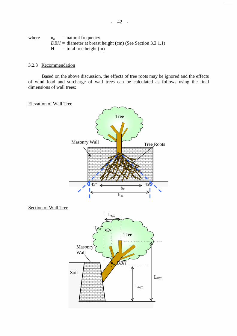
where na = natural frequency DBH = diameter at breast height (cm) (See Section 3.2.1.1) H = total tree height (m) 3.2.3 Recommendation Based on the above discussion, the effects of tree roots may be ignored and the effects of wind load and surcharge of wall trees can be calculated as follows using the final dimensions of wall trees: Elevation of Wall Tree
Section of Wall Tree
LWC
LST Tree
Masonry Wall
DBH
LWT
Soil
LSC
Tree
Masonry Wall Tree Roots
b45
bR 45°
45°

- 43 -
- 43 -
Calculation of Surcharge of Wall Tree Total dry biomass of wall tree, bm = Exp (-2.0127 + 2.4342lnDBH) Ratio(foliage) = Exp (-4.0813 + 5.8816 / DBH) Ratio(stem bark) = Exp (-2.0129 - 1.6805 / DBH) Ratio(stem wood) = Exp (-0.3065 - 5.4240 / DBH) Ratio(branch) = 1 - Ratio(foliage) - Ratio(stem bark) - Ratio(stem wood) Ratio(crown) = Ratio(foliage) + Ratio(branch) Ratio(truck) = Ratio(stem bark) + Ratio(stem wood) where DBH = Diameter at breast height (measured at 1.3 m above the trunk base) Surcharge of tree crown on wall per m width, FSC = bm x Ratio(crown) / s
Surcharge of tree trunk on wall per m width, FST = bm x Ratio(trunk) x 1.5 / s
where bR = root spread (extent of roots that hold firmly on wall face) b45 = 45° spreading from trunk base to wall toe B = base width of wall s = spread of loading = greater of [ (bR +2B) or b45 ] Overturning moment cause by surcharge of tree = FSC x LSC + FST x LST
where LSC = Lever arm of surcharge of tree crown against overturning LST = Lever arm of surcharge of tree trunk against overturning Calculation of Wind Force (if required) Force on crown per m width, FWC = 0.5 x (Σ AC qZ) / s
Force on trunk per m width, FWT = 1.2 x (Σ AT qZ) / s
or Force on crown per m width, FWC = 0.5 G x (Σ AC qZ) / s
Force on trunk per m width, FWT = 1.2 G x (Σ AT qZ) / s
whichever FWC and FWT are the greater
where qZ = Design wind pressures at height z (Table 6) qZ = design hourly mean wind pressure at height z (See Table 9) G = the dynamic magnification factor (See Section 3.2.2.4) AC = Area of crown frontal area
AT = Area of trunk frontal area
Overturning moment caused by wind force on tree = FWC x LWC + FWT x LWT
where LWC = Lever arm of wind load on tree crown against overturning LWT = Lever arm of wind load on tree trunk against overturning

- 44 -
4. EXAMPLES OF UPGRADING WORKS When a masonry wall is found to have an inadequate factor of safety, upgrading works should be carried out. Information search was carried out on examples of upgrading works on masonry retaining walls on the following aspects:
(i) preservation of existing trees on the walls; and (ii) preservation of the existing masonry pattern (or façade).
4.1 Search for Examples of Upgrading Works Letters were sent to professors of some universities in UK, Australia and Italy. However, they did not have any experiences on upgrading the stability of masonry retaining wall by preserving the existing facing and any trees growing on it. In order to review the existing methods on upgrading masonry walls in Hong Kong, records were collected from the following organisations:
(i) LPM Division 2, Geotechnical Engineering Office (GEO); (ii) CMWAL; (iii) other consultants; and (iv) Architectural Services Department (ArchSD).
LPM Division 2, Geotechnical Engineering Office (GEO) A list of project related to the study on masonry wall carried out by LPM Division 2, GEO was received in Dec 2004. (See Appendix D, Page D1) There were 10 features in the list. Two of them were not related to this study. One of them contained a masonry wall of 1.83 m high only and the upgrading works were carried out on the slope above the wall. Upgrading works of four of the features were not completed yet. The remaining three examples on upgrading of masonry walls preserved the existing trees. CMWAL Past upgrading works on masonry walls carried out by CMWAL were reviewed. Four examples were found on upgrading of masonry walls with masonry pattern retained. One example was found on both cases with masonry pattern partially retained and with existing trees preserved. No examples on upgrading masonry walls with both masonry pattern retained and existing trees preserved were found.

- 45 -
Other Consultants Letters were sent to 30 consultants by GEO in Dec 2004 requesting for records of methods on upgrading masonry walls with existing masonry pattern retained and/or existing trees preserved. Out of these 30 consultants, eight consultants replied and five of them provided relevant records. Three examples were found on both cases with masonry pattern retained and partially retained. One example on upgrading masonry walls with both masonry pattern partially retained and existing trees preserved was found. A summary of the replies from the consultants is included in Appendix D, Page D2. Architectural Services Department During the meeting for special task in 14 Dec 2004 between GEO and CMWAL, an example of upgrading of masonry wall with existing trees preserved was provided by GEO. Relevant records were collected in Architectural Services Department (ArchSD). 4.2 Preservation of the Existing Masonry Pattern (or Façade) Past methods of upgrading masonry works with existing masonry pattern retained were mainly using hand-dug caissons, mass concrete backfill and soil nails. Installation of soil nails normally retained the existing masonry pattern partially. Soil nail heads were noted in all of the examples except Feature No. 11SW-A/R1086. Soil nail heads were hidden behind the masonry blocks in Feature No. 11SW-A/R1086. However, some grout was noted on the wall face. The method using mass concrete backfill is similar to that using caissons. The main differences are that caissons are circular in plan and concrete rings are used during excavation. It appears that caissons are better in preserving trees because of less contact area to the back of walls.
Figure 15 - Feature No. 11SW-A/R1086 before and after Upgrading Works Using Soil Nails
- 46 -
- 46 -
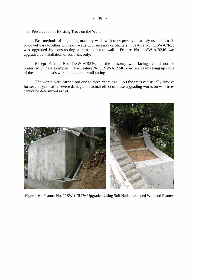
4.3 Preservation of Existing Trees on the Walls Past methods of upgrading masonry walls with trees preserved mainly used soil nails or dowel bars together with skin walls with recesses or planters. Feature No. 11SW-C/R38 was upgraded by constructing a mass concrete wall. Feature No. 11SW-A/R346 was upgraded by installation of soil nails only. Except Feature No. 11SW-A/R346, all the masonry wall facings could not be preserved in these examples. For Feature No. 11SW-A/R346, concrete beams tying up some of the soil nail heads were noted on the wall facing. The works were carried out one to three years ago. As the trees can usually survive for several years after severe damage, the actual effect of these upgrading works on wall trees cannot be determined as yet.
Figure 16 - Feature No. 11SW-C/R476 Upgraded Using Soil Nails, L-shaped Wall and Planter

- 47 -
- 47 -
Figure 17 - Feature No. 11SW-C/R38 Upgraded Using Mass Concrete Wall and Finished with the Old Granite Blocks
Figure 18 - Feature No. 11SW-A//R346 Upgraded Using Soil Nails The past examples on methods of upgrading masonry walls are summarized in the following table:

- 48 -
Table 10 - Past Example of Upgrading Works on Masonry Walls with or without Trees Growing on Them (Sheet 1 of 2)
Feature No. Location Upgrading
Method Tree
Preserved
Wall Facing
Preserved
Year of Completion
Designed by Remark
11SW-A/R22 Fuk On Lane Soil nails and skin wall
Y N 2004 GEO Recesses were provided to protect and preserve the trees.
11SW-C/CR120 Pokfulam Training Centre Complex, Wah Fu, HK Island
Skin wall Y N 2004 GEO Tree preserved by tree rings.
11SW-C/R38 Bethanie, 139 Pokfulam Road
mass concrete wall
Y N 2003 GEO Existing masonry wall was removed and a new reinforced concrete wall with a green face was constructed. The exposed surface of the new wall would be finished with the salvaged old granite blocks.
11NW-D/R50 (part)
No. 6 Knutsford Terrace Caisson NA Y 1997 CMW Active pressure assumed to be taken by the caisson only.
11SW-A/R147 No.2-4B Ying Fai Terrace Caisson NA Y 1999 CMW Existing wall thickened by caissons.
11SW-A/R634 (part)
No. 109-109B Robinson Road
Caisson NA Y 1993 CMW Existing wall thickened by caissons.
11SW-A/R679 Piccadily Mansion, Nos. 4-6A, Po Shan Road, Hong Kong
Mass concrete backfill
NA Y 2003 CMW
11SW-A/R1086 250 m North West from No. 63 Victoria Road HK
Soil nails NA Y 2004 CMW Soil nail heads hidden behind the masonry wall facing.
11SW-C/R476 The University of Hong Kong, 5-7 Sassoon Road
Soil nails, L-shaped wall and planter
Y N 2003 CMW
11SW-A/R298 Merry Terrace, 4A-4P, Seymour Road
Soil nails, skin wall and planter
Y N 2001 BBV
11SW-A/R109 North-west of Merry Terrace, Sheung Wan
Dowel bars and skin wall
Y N 1998 BCL Recesses were provided to protect and preserve the trees. Granite facing constructed at the wall facing.

- 49 -
Table 10 - Past Example of Upgrading Works on Masonry Walls with or without Trees Growing on Them (Sheet 2 of 2)
Feature No. Location Upgrading
Method Tree
Preserved
Wall Facing
Preserved
Year of Completion
Designed by Remark
11SW-A/R346 North of Pok Fu Lam Service Reservoir, along Pok Fu Lam Road
Soil nails Y P 2003 Fugro Architectural pattern made by concrete beam tying up part of soil nail heads were constructed on the wall surface.
11SW-A/R374 No. 101 Robinson Road, Hong Kong Lot No. I.L.719 s.C.R.P.
Soil nails NA P 2003 James Lau Continuous concrete beams tying up soil nail heads were constructed.
11SW-A/R802 Masonry Wall Portion, La Clare Mansion, No. 92 Pokfulam Road, Hong Kong
Soil nails NA P 2003 James Lau Some masonry blocks removed and replaced by soil nail head.
11SW-B/R548 (Portion)
No. 15 Bowen Road, Hong Kong
Soil nails NA P 2003 James Lau Continuous concrete beams tying up soil nail heads were constructed.
11SW-A/R563 65A & 65B Bonham Road and 2 Hing Hong Road
Soil nails and skin wall
Y N 2004 Scott Wilson
Soil nails were offset from tree root locations. The skin wall was span across. Random pattern stone facing finish were constructed at the wall facing.
11SW-A/R466, R467, R469, R470. R471,
R472
King George V Memorial Garden
Soil nails and RC skin wall
Y N 1996 ASD Dressed block facing constructed on RC skin wall.
Legend:
BCL Binnie Consultants Limited Y Yes BBV Binnie Black & Veatch Hong Kong Limited N No CMW C M Wong & Associates Ltd. P Partial Fugro Fugro (Hong Kong) Limited NA Not Applicable James Lau James Lau & Associates Ltd. Scott Wilson Scott Wilson (Hong Kong) Ltd. GEO Geotechnical Engineering Office ASD Architectural Service Department
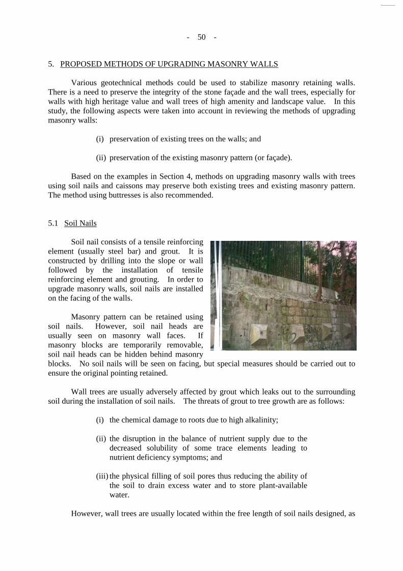
- 50 -
5. PROPOSED METHODS OF UPGRADING MASONRY WALLS Various geotechnical methods could be used to stabilize masonry retaining walls. There is a need to preserve the integrity of the stone façade and the wall trees, especially for walls with high heritage value and wall trees of high amenity and landscape value. In this study, the following aspects were taken into account in reviewing the methods of upgrading masonry walls:
(i) preservation of existing trees on the walls; and (ii) preservation of the existing masonry pattern (or façade).
Based on the examples in Section 4, methods on upgrading masonry walls with trees using soil nails and caissons may preserve both existing trees and existing masonry pattern. The method using buttresses is also recommended. 5.1 Soil Nails Soil nail consists of a tensile reinforcing element (usually steel bar) and grout. It is constructed by drilling into the slope or wall followed by the installation of tensile reinforcing element and grouting. In order to upgrade masonry walls, soil nails are installed on the facing of the walls. Masonry pattern can be retained using soil nails. However, soil nail heads are usually seen on masonry wall faces. If masonry blocks are temporarily removable, soil nail heads can be hidden behind masonry blocks. No soil nails will be seen on facing, but special measures should be carried out to ensure the original pointing retained. Wall trees are usually adversely affected by grout which leaks out to the surrounding soil during the installation of soil nails. The threats of grout to tree growth are as follows:
(i) the chemical damage to roots due to high alkalinity; (ii) the disruption in the balance of nutrient supply due to the
decreased solubility of some trace elements leading to nutrient deficiency symptoms; and
(iii) the physical filling of soil pores thus reducing the ability of
the soil to drain excess water and to store plant-available water.
However, wall trees are usually located within the free length of soil nails designed, as

- 51 -
- 51 -
they are located close to the wall faces. Therefore, left-in casing could be used within the free length of soil nails to seal-off the grout and reduce the threats. Behind masonry walls, there should be enough area within boundary for the construction of soil nails.
5.2 Buttresses
5.2.1 Conventional Buttresses Buttress is a structure, usually brick, stone or concrete, built against a wall for support or reinforcement. In order to upgrade masonry walls with trees, buttresses are built with spacing adjusted to minimize impacts on wall trees. Since buttresses are built in front of walls, soil and tree roots behind the walls are not disturbed or damaged. The bulk of the masonry wall facing can be retained. For conventional buttresses, there should be enough area in front of the walls for construction. This area will be occupied by buttresses and thus cannot be used for other purposes. The masonry facing will be slightly modified, as part of it will be blocked by the buttresses.
Tree
Tree roots
Soil nail head
Masonry wall Front face of masonry wall
Soil nail

- 52 -
- 52 -
Figure 19 - Conventional Buttresses in the University of Hong Kong
5.2.2 Flying Buttresses Besides conventional buttresses, flying buttresses can also be used. Flying buttresses may be in the form of as half or semi-arches. The elevated end of the arch supports the wall and the lower end of the arch is mounted on foundations, or on pillars or other flying buttresses. If necessary, beams could be built as extensions from the flying buttresses to provide additional support to the wall.
Front face of masonry wall
Tree
Tree roots
Conventional buttress
Masonry wall
~4 m
~2.5 m ~0.6 m
Dimensions
Masonry wall
Buttress

- 53 -
- 53 -
Flying buttresses have the same advantages as conventional buttresses. However, flying buttresses have fewer disadvantages than conventional buttresses. Construction of flying buttresses requires area in front of the walls. However, as flying buttresses stand apart from masonry walls and connect to them in semi-arch shape, the area between the toe of walls and flying buttresses will not be occupied. This area can be used for other purposes (e.g. footpath). The masonry facing will still be slightly modified using flying buttresses.
Figure 20 - A Flying Buttress in the University of Hong Kong
Tree
Tree roots
Flying buttress
Masonry wall
Front face of masonry wall
~3 m
Dimensions
~2 m
~2 m ~3 m
Masonry wall
Flying Buttress
~1 m

- 54 -
- 54 -
5.3 Hand-dug Caissons Caisson is an earth-retaining structure, or part thereof, the construction of which includes the excavation of a shaft in the ground by means of digging carried out by any person inside the shaft with or without the aid of machine tools. In order to upgrade masonry walls with trees, caissons are built behind the walls. The spacing between caissons should be adjusted as far as practicable to minimize damaging tree roots. As caissons are built behind masonry walls, masonry pattern can thus be fully retained. Caissons are excavated by hands. The disturbance to the surrounding soil and damages to masonry blocks are small. Cutting of large tree roots could also be avoided. According to ETWB Circular No. 09/1994, the use of hand-dug caissons requires approval from the Director of CEDD. For private project, under the jurisdiction of the Buildings Ordinance, hand-dug caisson of depth greater than 3 m would not be approved unless there is no alternative. Therefore, for caisson proposed to be more than 3 m depth, it must be demonstrated that there is no other practical alternative in preserving the masonry facing and the trees thereon. Caisson proposal is not effective to upgrade walls with large wall trees having an extensive spread of roots, as the spacing between caissons cannot be too large. Area should also be available behind the walls for the construction of caissons.
The following table summarized the comparisons between the above methods:
Tree roots
Front face of masonry wall
Caisson
Masonry wall
Tree

- 55 -
Table 11 - Advantages and Disadvantages / Limitations of Upgrading Methods on Masonry Walls with Tree
Method Advantages Disadvantages / Limitations
Soil Nail 1. Masonry pattern largely retained.
1. To reduce potential adverse effect on wall trees due to grouting, left-in casing need to be provided.
2. Masonry wall facings slightly modified.
3. Boundary constraint behind walls.
Conventional buttress
1. Soil and tree roots behind walls are not disturbed or damaged.
2. Masonry pattern largely retained.
1. Masonry wall facings slightly modified.
2. Area in front of walls required. 3. Area occupied by buttresses cannot
be used for other purposes.
Flying buttress 1. Soil and tree roots behind walls are not disturbed or damaged.
2. Masonry pattern largely retained.
1. Masonry wall facings slightly modified.
2. Area in front of walls required.
Caisson 1. Masonry pattern can be fully retained.
2. Damage to masonry block and large tree roots and disturbance to surrounding soil are small.
3. No leakage of grout to soil.
1. Spacing between caissons cannot be too large.
2. Special approval from relevant authority required.
3. Boundary constraint behind walls.
5.4 Recommendation In conclusion, in order to upgrade masonry walls with trees preserved and masonry pattern retained, installation of soil nails, construction of conventional buttresses, flying buttresses and caissons are recommended and the selection of upgrading method to be used should be based on the actual site conditions. 6. SPECIAL MEASURES ON UPGRADING MASONRY WALLS WITH TREES For the walls designated for special protection, specific precautionary measures could be adopted in the course of upgrading works and wall maintenance to ensure that the wall façade is not unduly modified, and the wall trees are not damaged. The guiding principles are discussed in Section 6.1. Details of the preservation

- 56 -
principles are discussed in Sections 6.2 - 6.4. The pertinent issues and their recommended precautionary measures for the proposed upgrading methods are included in Appendix E. 6.1 Guiding Principles It is pertinent to protect not only the visible tree parts, namely the stems and wall-surface roots, but also the hidden tree roots that have grown into the soil situated behind the wall and below the ground at the wall base. The overarching principles of wall protection in relation to stabilization works are:
(i) The integrity and appearance of the stone façade, including the masonry blocks and associated mortar and pointing, are preserved.
(ii) The tree stems (branches and foliage) and roots, including
aerial roots, on the wall face are not unduly damaged. (iii) The tree roots that have penetrated into the soil behind the
stone wall are not unduly damaged. (iv) The tree roots that have entered the soil situated on the slope
adjacent to the top of the wall are not unduly damaged. (v) The tree roots that have penetrated into the soil below the
ground at or near the wall base are not unduly damaged. (vi) The stabilized wall will continue to support the growth of
existing trees. Details of the preservation of existing masonry pattern (or façade), the protection of tree roots from damage and the continued growth of existing trees are discussed in the following sections. 6.2 Preserving the Existing Masonry Pattern (or Façade) Walls to be preserved should have their façade kept intact and the pointing should not be modified. Any cement mix used in re-pointing, if deemed absolutely necessary, should match as far as possible the original material in terms of composition, colour and workmanship. Dry walls should remain undisturbed, and their joints should not be filled with mortar. Walls without original pointing should not be given new pointing, or above all they should not have the joints buttered over by cement. Any stones that need to be temporarily removed for soil nailing work and other maintenance tasks should be very carefully extracted so as not to damage them, and they should be replaced with due respect to the full restoration of the façade appearance. The use of plaster to emulate the stone in covering up the soil-nail opening should not be accepted. To ensure full restoration of the façade, photographs of the façade can be taken, and number or reference can be marked on every masonry stones before their removal for any works.
- 57 -
- 57 -
6.3 Protecting Tree Roots and Stems From Damage
6.3.1 Importance of Protecting Tree Roots from Damage Trees have developed through evolution two different strategies to support its aboveground masses and to react to mechanical forces that may disturb its balance and stability. Mechanical stresses on trees could be imposed by wind or tilting (gravity). Coniferous trees develop new compression wood on the downwind or falling side to support or push up the tree against failure. On the contrary, broadleaf trees react by developing new tension wood on the upwind or opposite side to pull up the tree against failure. Whether pushing (compression) or pulling (tension), the effect is an attempt to correct the imbalance by shifting the tree towards the upright or equilibrium position. Banyan is a broadleaf tree that adopts the pulling or tension wood strategy. A wall tree has an inherently unstable perch. Its stem attempts to grow largely vertically upwards in response to negative geotropism. In doing so, it must develop adequate anchorage to support itself against gravity pull. Additional reserve strength must be made available to cater to the exigencies of the pressure imposed by strong wind. The trunk and roots of a wall tree would have to develop tension wood to pull the tree weight like ropes to counteract the force of collapse. The larger the root, the more role it plays in securing the tree on the vertical habitat. Any attempt to damage or cut the roots, especially the main roots, may bring serious consequences on tree stability. The weakened tree may collapse without warning on pedestrians, vehicles or properties. It will induce the formation of hazard trees in our compact city, and substantially trim the life span and ecological value of the damaged tree. Some examples of root severance of wall trees in recent years had resulted in loss of poise and tree collapse. 6.3.2 Tree Root Pruning Where stones are shifted at the wall ends to such an extent that a potential hazard of stone fall or wall destabilization may be induced, only the specific roots in question could be pruned to stop the displacement. Detailed field assessment could judge whether appropriate management intervention is necessary to abate the hazard. There is little field evidence to support the need for pre-emptive pruning of tree roots to prevent stone displacement. Where root pruning is found necessary, an overall evaluation of wall-tree relationship is recommended to judge the extent position and method of root pruning. The cardinal principle is to minimize the amount of root removal so as to forestall tree decline and possible tree destabilization. The following general principles of pruning the roots of wall trees are recommended:
(i) Prune only if it is absolutely necessary, that is to prune only if non-action will permit the wall instability problem to aggravate such that it may degenerate into a hazard;
(ii) Root pruning should bear in mind that it could destabilize
the tree and hence in solving one “perceived” problem,
Perch A perch is a branch that serves as a resting place for birds, or an attachment surface for epiphytes (plants that grow on the surface of other plants).

- 58 -
another problem (hazard) and a long-term management worry and burden could be generated; and
(iii) Prune the minimal amount of roots that is sufficient to
alleviate the wall instability hazard, and take care not to remove roots unnecessarily.
Concerning the specifics, the actual location, amount and method of root removal have to rely on expert judgment in the field, to be assessed on an individual-tree basis. 6.3.3 Trimming of Branches, Leaves or Roots of Wall Trees Trimming a tree’s foliage and branches could reduce its capability to produce food and hence weaken the tree and make it susceptible to attack by pests and pathogens. Therefore, wall trees should only be pruned if it is absolutely necessary. When the following conditions are found, pruning may found necessary:
(i) there is unequivocal evidence that they have damaged a wall by displacing masonry blocks;
(ii) they have a very high probability of destabilizing wall; (iii) they obstruct vehicular traffic; and (iv) they have been weakened by wind, pest or pathogens and as
a result have become potentially hazardous. If pruning is found to be necessary, it should be confined to the abatement of the specific problem in question to minimize the amount of tissue removal. As different trees and different problem cases require different pruning approaches, the actual pruning extent has to be decided on the basis of individual trees in the field and the pruning should be carried out only by knowledgeable and experienced landscape contractors using clean and sharp tools. Care should be taken on the position and angle of cuts in the case of branch removal to minimize the chance of wound invasion by wood-decay fungi. 6.4 Continued Growth of Existing Trees As it is the case for normal ground-growing trees, some roots may decline or die due to various reasons, such as disease, pest, injury, decay, drought, waterlogging, soil contamination, sealing and compaction. For a healthy tree, new roots would continually be formed to expand the root catchment and to compensate for the loss roots. Wall growth conditions must remain continually suitable for root growth in order that the wall tree can continue to thrive. Keeping joints of masonry walls unsealed, which is usually ignored, is one of the important measures for the continued growth of existing wall trees.

- 59 -
- 59 -
6.4.1 Keeping Joints Unsealed The tendency of aerial roots of Banyans to grow into the crevices between stones is tied to their natural negative phototropism. In other words, they tend to grow away from light and into the dark joints. It is largely the presence of joints in the older generation of walls that has permitted the unique ecological phenomenon of stone wall trees to flourish in Hong Kong. Recently, some old stone walls with trees have been too assiduously maintained, resulting in extensive sealing and even buttering over of joints with new cement mixtures. Some walls have virtually all the joints effectively sealed by cement. The sealing is so thorough that even living roots in the joints were embedded in cement. Such sealing will deprive the wall trees of a pertinent raison d’être for their survival. New roots will no longer be able to enter the joints to obtain sustenance in the soil lying behind the wall. Existing roots will suffer from inadequate aeration as the joints are essential in allowing the entry of air into the soil and carbon dioxide from root respiration to dissipate through the joints. Where the cement covers the existing roots, their continued growth which requires secondary thickening will be curtailed. Any root thickening would result in self-girdling damage that could lead to root decay and possible root death. The long-term effect of such overzealous wall maintenance is to suppress tree growth, induce decline and eventually leading to premature tree death. In order to let the wall growth conditions continually suitable for root growth, any unsealed joints of masonry walls should be kept unsealed. For deteriorated mortar joints, the mortar may be removed and replaced by new one and no significant alteration should be made on the wall condition. The pertinent issues and their recommended precautionary measures for the proposed upgrading methods are included in Appendix E. 6.5 Conclusion In conclusion, any measure that could impose injuries or harms on trees should be reviewed and modified to make them tree friendly. Contractors should be coached about the reasons for adopting the new wall maintenance techniques, and their performance should be monitored to prevent overzealous work. Significant historical walls and trees should receive special attention, and any maintenance work should be custom-designed based on scientific and filed study of the real-world situation. 7. SAFETY STANDARD FOR CHECKING MASONRY RETAINING WALLS WITH
TREES Based on the above study, stability of masonry walls with trees can be assessed and the existing and upgraded conditions of the walls should be checked against safety standards. GEO (1984) (hereinafter referred to as “Geotechnical Manual for Slopes”), GEO (1982) (hereinafter referred to as “GEOGUIDE 1 (1982)”) and GEO (1993) (hereinafter referred to as “GEOGUIDE 1 (1993)”) are the current guides used in Hong Kong providing standards of

- 60 -
- 60 -
practice that should be adopted for the design, construction and maintenance of masonry walls. In the following sections, the approaches for checking the stability of masonry walls, the current safety standards for masonry walls and the recommended safety standards for masonry walls with trees are discussed. 7.1 Approaches There are two approaches for checking the stability of retaining walls in Hong Kong:
(i) limit state approach; and (ii) factor of safety approach.
Geotechnical Manual for Slopes and GEOGUIDE 1 (1982) used factor of safety approach. The latest Geoguide, GEOGUIDE 1 (1993), recommended limit state approach. However, the geotechnical standards set out in the latest Geoguide are for new permanent earth retaining walls on land. Assessments of existing retaining walls are beyond its scope. As masonry walls with trees are existing retaining walls, the geotechnical standards set out in Geotechnical Manual for Slopes and GEOGUIDE 1 (1982) should be followed. Therefore the factor of safety approach is recommended for masonry walls with trees. 7.2 Existing Walls, New Walls and Remedial Works Geotechnical Manual for Slopes recommended minimum values on factor of safety for the following two separate cases:
(i) the design of a new wall where design parameters are derived from geological and geotechnical investigation; and
(ii) the analysis of an existing wall and for the design of
remedial and preventive works. According to the Geotechnical Manual for Slopes, when analysing an existing gravity retaining wall to determine the extent of any remedial or preventive works required, the factors of safety for case (ii) may be used as long as rigorous structural, geological and geotechnical investigation are conducted (which include a thorough examination of wall maintenance history, groundwater records, rainfall records and any wall monitoring records) and the loading remain substantially the same as those of the existing wall. In checking the stability of masonry wall with trees, if the generalized parameters in the preceding sections are adopted and without specific test being conducted, then such analysis cannot satisfy the criteria for rigorous structural investigation, not to mention whether the geological and geotechnical investigation are considered rigorous or not. Therefore, the recommended minimum factors of safety for the design of a new wall, i.e. case (i), should be used for both the stability analysis and the design of upgrading works for masonry wall with trees.
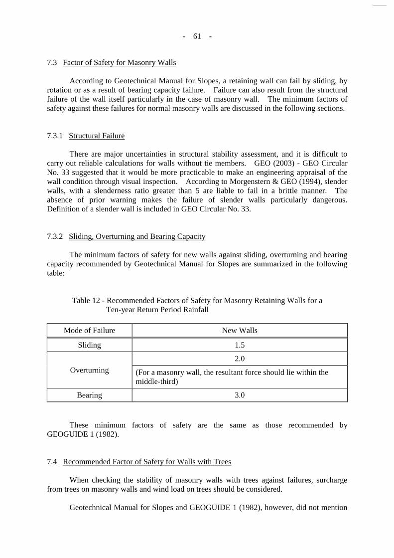
- 61 -
- 61 -
7.3 Factor of Safety for Masonry Walls According to Geotechnical Manual for Slopes, a retaining wall can fail by sliding, by rotation or as a result of bearing capacity failure. Failure can also result from the structural failure of the wall itself particularly in the case of masonry wall. The minimum factors of safety against these failures for normal masonry walls are discussed in the following sections. 7.3.1 Structural Failure There are major uncertainties in structural stability assessment, and it is difficult to carry out reliable calculations for walls without tie members. GEO (2003) - GEO Circular No. 33 suggested that it would be more practicable to make an engineering appraisal of the wall condition through visual inspection. According to Morgenstern & GEO (1994), slender walls, with a slenderness ratio greater than 5 are liable to fail in a brittle manner. The absence of prior warning makes the failure of slender walls particularly dangerous. Definition of a slender wall is included in GEO Circular No. 33. 7.3.2 Sliding, Overturning and Bearing Capacity The minimum factors of safety for new walls against sliding, overturning and bearing capacity recommended by Geotechnical Manual for Slopes are summarized in the following table:
Table 12 - Recommended Factors of Safety for Masonry Retaining Walls for a Ten-year Return Period Rainfall
Mode of Failure New Walls
Sliding 1.5
Overturning
2.0
(For a masonry wall, the resultant force should lie within the middle-third)
Bearing 3.0
These minimum factors of safety are the same as those recommended by GEOGUIDE 1 (1982). 7.4 Recommended Factor of Safety for Walls with Trees When checking the stability of masonry walls with trees against failures, surcharge from trees on masonry walls and wind load on trees should be considered. Geotechnical Manual for Slopes and GEOGUIDE 1 (1982), however, did not mention

- 62 -
- 62 -
the wind effect when recommending safety standards. Reference has therefore been made to the Building (Construction) Regulations and BD (2004c) (hereinafter referred to as “Code of Practice for Foundations”) to study the minimum factor of safety if the increased in disturbing force is solely due to wind. 7.4.1 Structural Failure As discussed in Section 3, tree roots do not have adverse effect on the structural integrity of masonry walls and it is difficult to carry out reliable stability analysis on the structural integrity. Therefore, the usual practice may be followed and an engineering appraisal of structural integrity of masonry walls with trees may be made. A detailed study on the structural stability of masonry retaining walls is available in Chan (1996). 7.4.2 Sliding, Overturning and Bearing Capacity
7.4.2.1 Sliding Building (Construction) Regulations and Code of Practice for Foundations both recommended a minimum factor of 1.5 on sliding force due to loads with and without wind loads:
(i) Building (Construction) Regulations stated that “the resistance to the sliding force acting thereon shall be not less than 1.5 times the sliding force due to any loads”.
(ii) Code of Practice for Foundations stated that “the sliding
resistance shall be at least 1.5 times the sliding force due to any loads.”
Therefore, the minimum factor on sliding force for masonry walls with trees is recommended to be the same as the normal one (1.5 due to wind load and other loads for the design of new wall). 7.4.2.2 Overturning In checking the stability against overturning, Building (Construction) Regulations and Code of Practice for Foundations both recommended factors of 1.5 and 2 on overturning moment due to wind loads and loads other than wind loads respectively:
(iii) Building (Construction) Regulations stated that “the resistance to the overturning moment acting thereon shall be not less than 1.5 times the overturning moment due to wind loads and 2 times the overturning moment due to loads other than wind loads.”
(iv) Code of Practice for Foundations stated that “the
overturning moment resistance shall be at least 1.5 times

- 63 -
- 63 -
the overturning moment due to wind loads” and “2 times the overturning moment due to loads other than wind loads and floatation, with the overturning moment resistance taken as the sum of the stabilizing moment due to the minimum dead loads plus that due to any permitted anchoring resistance.”
The above recommended factor of 2 on overturning moment due to loads other than wind loads is the same as the required factor of safety against overturning for the design of new walls as stated in Geotechnical Manual for Slopes and GEOGUIDE 1 (1982). Therefore, a factor of 1.5 is recommended on overturning moment due to wind loads for the design of new walls. 7.4.2.3 Bearing Building (Construction) Regulations and Code of Practice for Foundations both recommended that the bearing capacity might be increased by 25% when such an increase is solely due to wind effects:
(i) Building (Construction) Regulations stated that “the allowable capacity of foundations for bearing, bond or friction resisting the combined effects of dead, imposed and wind loads may be increased by not more than 25% where such increase is solely due to wind loads.”
(ii) Code of Practice for Foundations stated that “the allowable
capacity of the soil/rock under working loads where any foundation is founded “may be increased by 25% when such increase is solely due to wind effects.”
Based on the Building (Construction) Regulations and Code of Practice for Foundations, a factor of 2.4 (= 3 / 1.25) is recommended on bearing force due to combined effects of dead, imposed and wind loads for the design of new walls. 7.5 Conclusion A retaining wall with trees can fail by structural failure, sliding, overturning and bearing failure. Surcharge from trees on masonry walls and wind loads on trees should be considered. For structural integrity of masonry walls with trees, an engineering appraisal may be made. A detailed study on the structural stability of masonry retaining walls is available in Chan (1996). In checking the stability of masonry walls with trees against sliding and overturning failures, factor of safety approach with local factors of safety is recommended. The total forces or moments resisting failure should not be less than the total forces or moments

- 64 -
- 64 -
causing failure with factors of safety applied. That is,
R γ1Floads other than wind + γ2Fwind load only where R = resistance force or moment Floads other than wind = forces or moments causing failure due to loads other than wind Fwind load only = forces or moments causing failure due to wind load only γ1 = factor of safety applied on Floads other than wind (See Table 13)
γ2 = factor of safety applied on Fwind load only (See Table 13) The resistance should be taken as the sum of the stabilizing force or moment due to the minimum dead loads plus that due to any permitted anchoring resistance. In checking the bearing, factor of safety approach with global factors of safety is recommended. That is, qc τ1qloads other than wind qc τ2qcombined effects where qc = bearing capacity qloads other than wind = bearing due to loads other than wind qcombined effects = bearing due to combined effects of dead, imposed and wind
loads τ1 = factor of safety applied on qloads other than wind (See Table 14)
τ2 = factor of safety applied on qcombined effects (See Table 14) Since the criteria discussed in Section 7.2 cannot be satisfied for a wall with trees, the recommended factors of safety for new walls should be adopted for the analysis of existing masonry walls and the design of upgrading works. The factors of safety applied to the loads causing failure are recommended and summarized in Tables 13 and 14.
Table 13 - The Recommended Factors of Safety Applied to Loads Causing Failure for Masonry Walls with Trees
Type of Loads
Recommended Factors of Safety
Loads Other Than Wind (Earth Pressure)
(γ1)
Wind Load Only (γ2)
Sliding 1.5 1.5
Overturning 2 1.5
(For a masonry wall, the resultant force should lie within the middle-third)
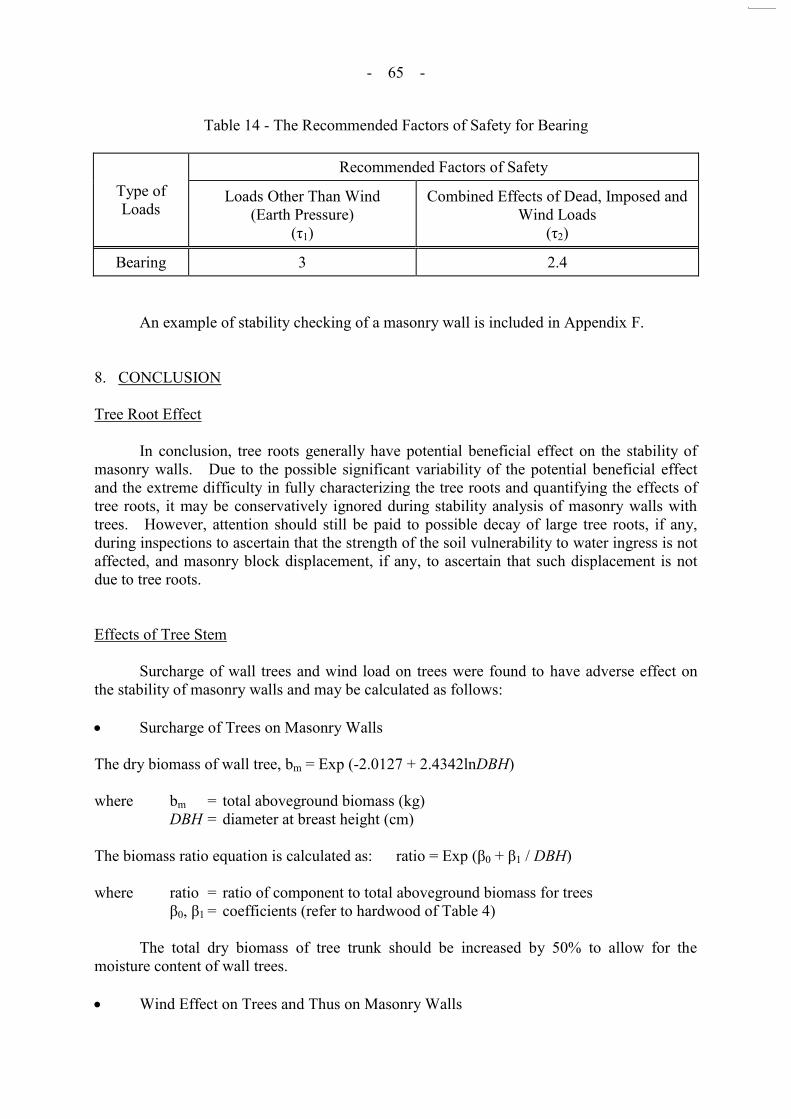
- 65 -
- 65 -
Table 14 - The Recommended Factors of Safety for Bearing
Type of Loads
Recommended Factors of Safety
Loads Other Than Wind (Earth Pressure)
(τ1)
Combined Effects of Dead, Imposed and Wind Loads
(τ2)
Bearing 3 2.4 An example of stability checking of a masonry wall is included in Appendix F. 8. CONCLUSION Tree Root Effect In conclusion, tree roots generally have potential beneficial effect on the stability of masonry walls. Due to the possible significant variability of the potential beneficial effect and the extreme difficulty in fully characterizing the tree roots and quantifying the effects of tree roots, it may be conservatively ignored during stability analysis of masonry walls with trees. However, attention should still be paid to possible decay of large tree roots, if any, during inspections to ascertain that the strength of the soil vulnerability to water ingress is not affected, and masonry block displacement, if any, to ascertain that such displacement is not due to tree roots. Effects of Tree Stem Surcharge of wall trees and wind load on trees were found to have adverse effect on the stability of masonry walls and may be calculated as follows: Surcharge of Trees on Masonry Walls The dry biomass of wall tree, bm = Exp (-2.0127 + 2.4342lnDBH) where bm = total aboveground biomass (kg) DBH = diameter at breast height (cm) The biomass ratio equation is calculated as: ratio = Exp (β0 + β1 / DBH) where ratio = ratio of component to total aboveground biomass for trees β0, β1 = coefficients (refer to hardwood of Table 4) The total dry biomass of tree trunk should be increased by 50% to allow for the moisture content of wall trees. Wind Effect on Trees and Thus on Masonry Walls

- 66 -
- 66 -
In the assessment of stability of retaining wall with trees, professional judgement should be exercised regarding whether the root anchorage is strong enough to sustain the design wind forces. If not, the effects of wind forces on wall trees could be ignored as far as the consequential effect on masonry walls is concerned. The wind force induced on trees, Static response: F = Σ CD AZ qZ or Dynamic response: F = G Σ CD qZ AZ whichever is greater where F = the wind force (kN) CD = the drag coefficient = 0.5 for tree crown and 1.2 for tree trunk AZ = the frontal area of that part corresponding to qZ or qZ (m2) qZ = design wind pressure at height z (kPa) (refer to Table 6) qZ = design hourly mean wind pressure at height z (kN) (See Table 9) G = the dynamic magnification factor (See Section 3.2.2.4) Proposed Methods of Upgrading Masonry Walls In order to upgrade masonry walls with the existing trees preserved and the existing masonry pattern retained, installation of soil nails, construction of caissons, flying buttresses or a combination of the methods are recommended for different site conditions. Special Measures on Upgrading Masonry Walls with Trees Special measures should be implemented during upgrading of masonry walls which deserve preservation of existing trees and existing masonry pattern. Any measures that could impose injuries or harm on trees should be reviewed and modified to make them tree-friendly. The joints between masonry blocks should not be sealed. Besides masonry blocks, pointing should not be modified. Safety Standard for Checking Masonry Retaining Walls with Trees A retaining wall with trees can fail by structural failure, sliding, overturning and bearing failure. Surcharge from trees on masonry walls and wind loads on trees should be considered. For structural integrity of masonry walls with trees, an engineering appraisal may be made. A detailed study on the structural stability of masonry retaining walls is available in Chan (1996). In checking the stability of masonry walls with trees against sliding, overturning and bearing failures, the resistance should not be less than the forces or moments causing failure with factors of safety applied. The factors of safety applied to the forces or moments causing failure are recommended in Table 13. The factors of safety for bearing are recommended in Table 14.

- 67 -
- 67 -
9. REFERENCES AFCD (2003). Measurement of Diameter at Breast Height (DBH). Nature Conservation
Practice Note No. 02/2003. Agriculture, Fisheries and Conservation Department, The Government of the Hong Kong Special Administrative Region.
BD (2004a). Code of Practice on Wind Effects in Hong Kong 2004. Buildings
Department, Hong Kong Special Administrative Region. BD (2004b). Explanatory Material to The Code of Practice on Wind Effects in Hong Kong
2004. Buildings Department, Hong Kong Special Administrative Region. BD (2004c). Code of Practice for Foundations. Buildings Department, Hong Kong Special
Administrative Region. Building (Construction) Regulations. The Government of the Hong Kong Special
Administrative Region. Chan, Y.C. (1996). Study of Old Masonry Retaining Walls in Hong Kong. GEO Report
No. 31, Geotechnical Engineering Office, Civil Engineering Department, The Government of the Hong Kong Special Administrative Region.
Cucchi, Veronique, Meredieu, Celine & Stokes, Alexia (2004). Root anchorage of inner and
edge trees in stands of Maritime pine (Pinus pinasterAit.) growing in different podzolic soil conditions. Trees, 18: 460-466.
Gray, Donald H. & Sotir, Robbin B. (1995). Biotechnical and Soil Bioengineering Slope
Stabilization: a practical guide for erosion control. Greenway, D.R. (1987). Vegetation and Slope Stability. Slope Stability: Geotechnical
Engineering and Geomorphology. Edited by M.G. Anderson and K.S. Richards, Chichester [West Sussex]: Wiley.
GEO (1982). Guide to Retaining Wall Design. Geoguide 1, Geotechnical Engineering
Office, Civil Engineering Department, The Government of the Hong Kong Special Administrative Region.
GEO (1984). Geotechnical Manual for Slopes (2nd Edition). Geotechnical Engineering
Office, Civil Engineering Department, The Government of the Hong Kong Special Administrative Region.
GEO (1993). Guide to Retaining Wall Design (2nd Edition). Geoguide 1, Geotechnical
Engineering Office, Civil Engineering Department, The Government of the Hong Kong Special Administrative Region.
GEO (2003). Guidelines for Assessment of Old Masonry Walls in Geotechnical Studies and
for Action to be Taken on Private Walls. GEO Circular No. 33, Geotechnical Engineering Office, Civil Engineering Department, The Government of the Hong Kong Special Administrative Region.

- 68 -
Jenkins, Jennifer C., Chojnacky, David C., Heath, Linda S. & Birdsey, Richard A. (2003). National-Scale Biomass Estimators for United States Tree Species. Forest Science, 49(1): 12-35.
Jim, C.Y. (1988). Preservation of a Large Chinese Banyan on a Construction Site. Journal
of Arboriculture, 14(7): 176-180. Jim, C.Y. (1998). Old stone walls as an ecological habitat for urban trees in Hong Kong.
Landscape and Urban Planning (Amsterdam), 42(1): 29-43. Johnson, R.C. JR., Ramey, G.E. & O’Hagan, D. S. (1982). Wind Induced Forces on Trees.
Journal of Fluids Engineering, 104: 25-30. Lee, Ivan W.Y. (1985). A review of vegetative slope stabilisation. HKIE Geotechnical
Group paper For publication only, pp 9-21. Lei, Y.C., Zhang, S.Y. & Zehui Jiang (2005). Models for predicting lumber bending MOR
and MOE based on tree and stand characteristics in black spruce. Wood Sci Technol, 39: 37-47.
Mayhead, G.J. (1973). Drag Coefficients for British Forest Trees Derived from Wind
Tunnel Studies. Agricultural Meteorology, 12: 123-130. Moore, John R. (2000). Differences in maximum resistive bending moments of Pinus
radiata trees grown on a range of soil types. Forest Ecology and Management, 135: 63-71.
Moore, John R. & Maguire, Douglas A. (2003). Natural sway frequencies and damping
ratios of trees: concepts, review and synthesis of previous studies. Trees, 18: 195-203. Morgenstern, N.R. & GEO (1994). Report on the Kwun Lung Lau Landslide of 23 July
1994. GEO Report No. 103, Geotechnical Engineering Office, Civil Engineering Department, The Government of the Hong Kong Special Administrative Region.
Peltola, Heli, Kellomaki, Seppo, Hassinen, Alpo & Granander, Markku (2000). Mechanical
stability of Scots pine, Norway spruce and birch: an analysis of tree-pulling experiments in Finland. Forest Ecology and Management, 135: 143-153.
P.G. Biddle (1998). Tree Root Damage to Buildings, Volume 1, Causes, Diagnosis and
Remedy. Rudnicki, Mark, Mitchell, Stephen J. & Novak, Michael D. (2004). Wind tunnel
measurements of crown streamlining and drag relationships for three conifer species. Canadian Journal of Forest Research, 34(3): 666-676.
Spatz, Hanns-Christof & Bruechert, Franka (2000). Basic biomechanics of self-supporting
plants: wind loads and gravitational loads on a Norway spruce tree. Forest Ecology and Management, 135: 33-44.
- 69 -
- 69 -
Stathers, R.J., Rollerson, T.P. & Mitchell, S.J. (1994). Windthrow Handbook for British Columbia Forests. Research Program Working Paper 9401, Ministry Forests Research Program.
Sun, Meng, Jepson, Allan D. & Fiume, Eugene (2003). Video Input Driven Animation
(VIDA). Proceedings of the IEEE International Conference on Computer Vision, vol. 1, pp 96-103.
USDA (1999). Wood Handbook - Wood as an Engineering Material. Forest Products
Laboratory, Forest Service, United States Department of Agriculture. Wang, Song-Yung, Lin, Cheng-Jung & Chiu, Chih-Ming (2005). Dynamic modulus of
elasticity and bending properties of young Taiwania trees grown with different thinning and pruning treatments. The Japan Wood Research Society, 51: 1-6.
WBTC (1999). Geotechnical Manual for Slopes, Guidance on Interpretation and Updating.
WBTC No. 13/99, The Government of the Hong Kong Special Administrative Region.

- 70 -
APPENDIX A

A1
Chinese Name of the 30 Species of Trees Growing on Masonry Walls in Hong Kong
Scientific Name Common Name Family
Ficus microcarpa Chinese banyan 榕樹 (細葉榕) Moraceae 桑科
Ficus superba Superb fig 筆管榕 Moraceae 桑科
Ficus hispida Rough-leaf stem fig 對葉榕 (牛乳樹) Moraceae 桑科
Ficus virens Big-leaved fig 黃葛樹 (大葉榕) Moraceae 桑科
Celtis sinensis Chinese hackberry 朴樹 Ulmaceae 榆科
Broussonetia papyrifera Paper mulberry 構樹 Moraceae 桑科
Ficus variegata Red-stem fig 青果榕 Moraceae 桑科
Ligustrum sinense Chinese privet 山指甲 Oleacae 木犀科
Maesa perlarius (nil) 鯽魚膽 Myrsinaceae 紫金牛科
Ficus religiosa Peepul tree 菩提樹 Moraceae 桑科
Bridelia monoica Pop-gun seed 土蜜樹 (逼迫仔) Euphorbiaceae 大戟科
Litsea glutinosa Pond spice 潺槁樹 Lauraceae 樟科
Macaranga tanarius Elephant’s ear 血桐 Euphorbiacae 大戟科
Cassia surattensis Sunshine tree 黃槐決明 (黃槐) Caesalpiniaceae 蘇木科
Mallotus paniculatus Turn-in-the-wind 白楸 Euphorbiaceae 大戟科
Cratoxylum ligustrinum Yellow-cow wood 黃牛木 Hypericaceae 山竹子科
Dalbergia balansae South China rosewood 南嶺黃檀 Papilionaceae 蠂形花科
Alangium chinense Chinese alangium 八角楓 Alangiaceae 八角楓科
Delonix regia Flame of the forest 鳳凰木 Caesalpiniaceae 蘇木科
Albizia lebbeck Lebbeck tree 大葉合歡 Mimosaceae 含羞草科
Aporusa chinensis Aporusa 銀柴 (大沙葉) Euphorbiaceae 大戟科
Bauhinia blakeana Hong Kong orchid tree 洋紫荊 Caesalpiniaceae 蘇木科
Carica papaya Papaya 番木瓜 Cariaceae 番木瓜科
Liquidambar formosana Sweet gum 楓香 Hamelidaceae 金縷梅科
Litsea monopetala Persimmon-leaf litsea 假柿木薑子 (假柿樹)
Lauraceae 樟科
Nerium indicum Oleander 夾竹桃 Apocynaceae 夾竹桃科
Punica granatum Pomegranate 安石榴 Punicaceae 安石榴科
Sapium sebiferum Tallow tree 烏桕 Euphorbiaceae 大戟科
Schefflera octophylla Ivy tree 鴨腳木 Araliaceae 五加科
Thevetia peruviana Yellow oleander 黃花夾竹桃 Apocynaceae 夾竹桃科

- 72 -
APPENDIX B


B2

B3

B4

B5

B6

B7

B8

B9

B10

B11

B12

B13

B14
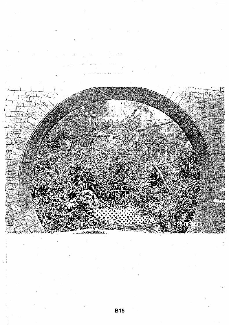
B15

B16

B17

B18

B19

B20
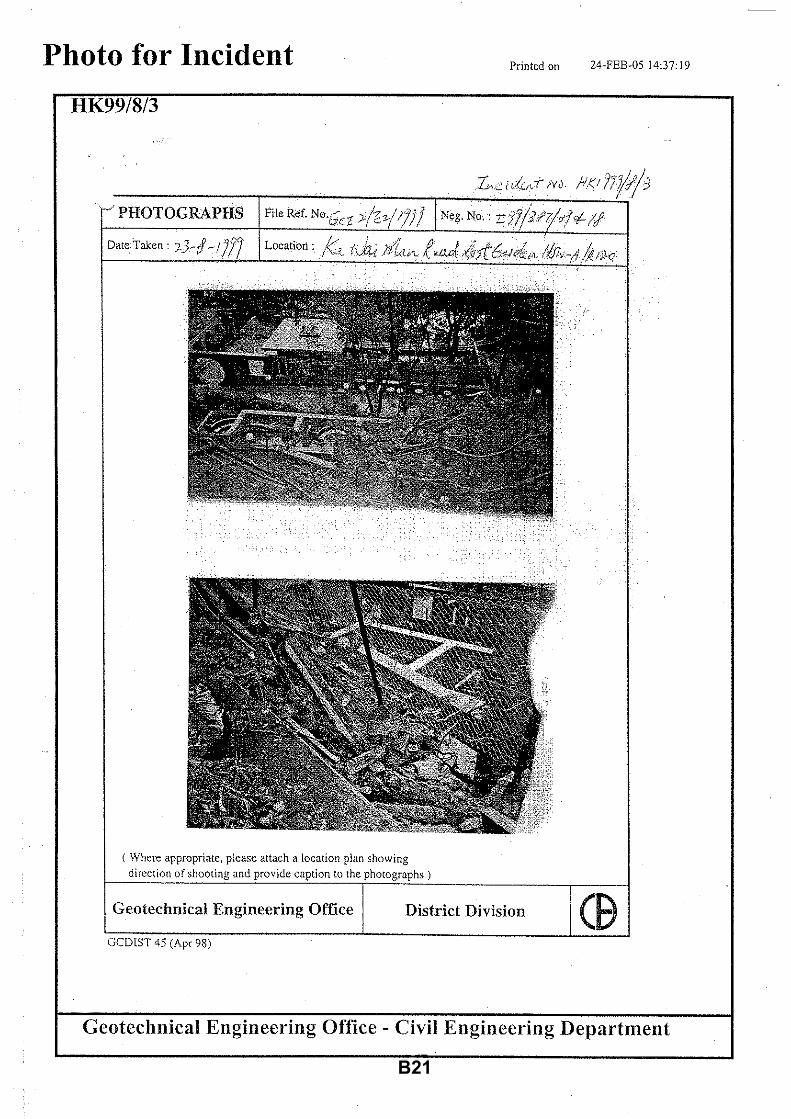
B21

B22

B23

B24
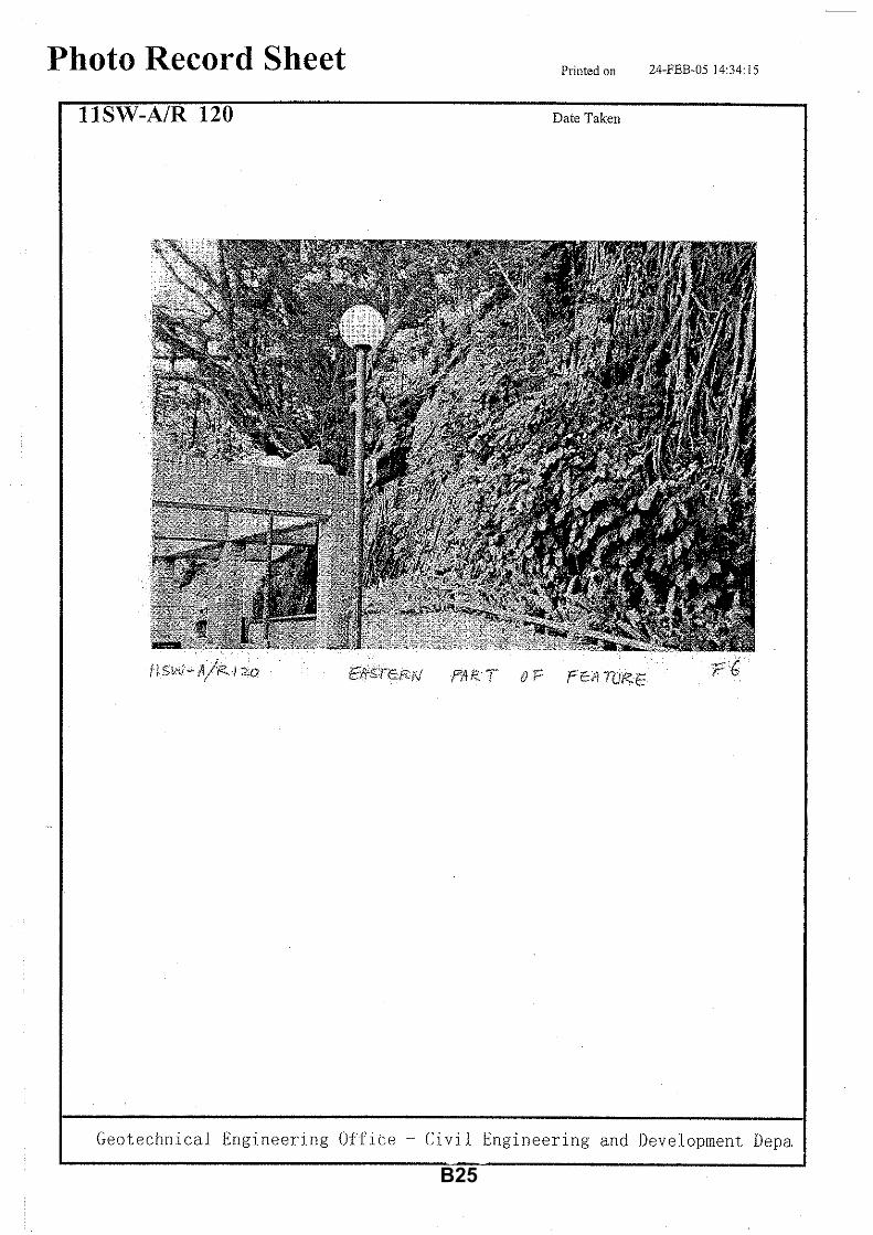
B25

B26

B27

B28

B29

B30

B31

B32

B33

B34

B35

B36

B37

B38

B39

B40

B41

B42

B43

B44

B45

B46

B47

B48

B49

B50

B51

B52
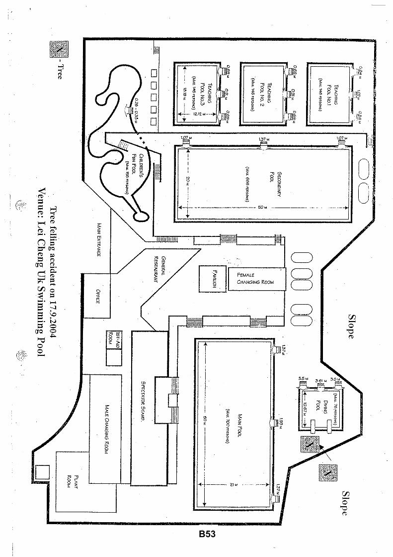
B53

B54

B55

B56

B57
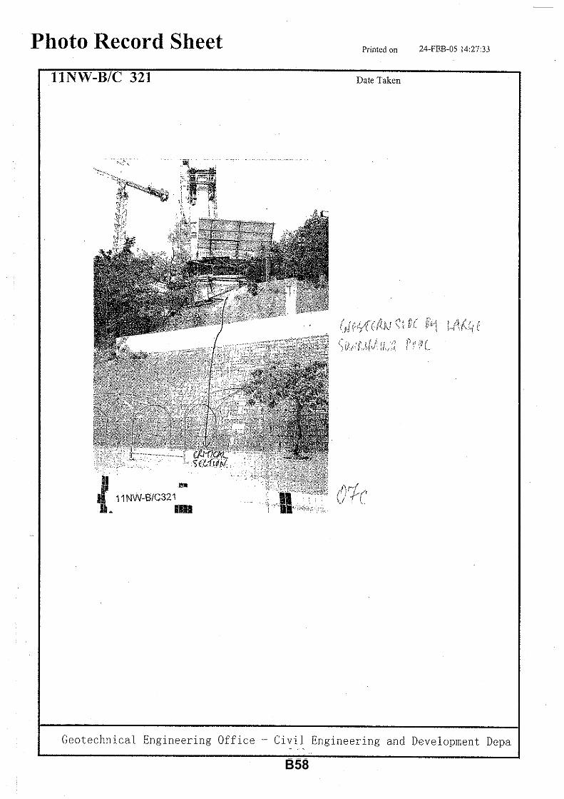
B58
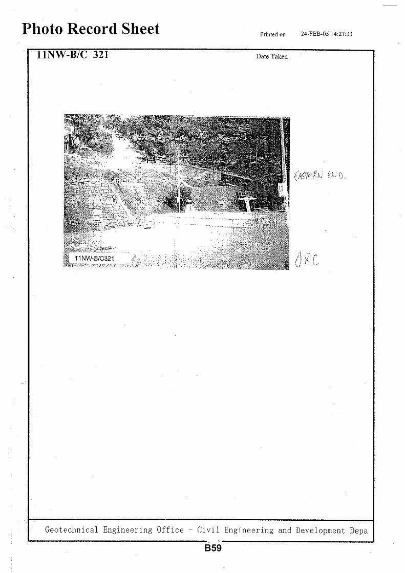
B59

B60

- 133 -
APPENDIX C


- 136 -
APPENDIX D


- 139 -
APPENDIX E

E1
E.1 SOIL NAIL METHOD The preferred method is to hide the soil nail heads behind masonry blocks, and hence it is necessary to extract selected blocks, install the soil nails, and then reinstate the blocks such that little evidence of disturbance is left. The following precautionary measures are proposed to minimize impacts on walls and trees:
(i) Physical breakage of masonry blocks
• Avoid breaking the block in prying it; • Avoid dropping the extracted block; • Avoid physical impact on the wall by construction vehicles and machinery;
(ii) Chipping corners off masonry blocks
• Avoid chipping the block corners in prying it; • Avoid dropping the extracted block;
(iii) Cracking masonry blocks • Avoid cracking the block in prying it; • Avoid dropping the extracted block; • Avoid physical impact on the wall by construction vehicles and machinery;
(iv) Staining masonry blocks with cement
• Do not permit piling of construction materials against the wall; • Avoid staining the wall face by wet cement; • Shield both the target and adjacent blocks to avoid staining by cement; • Trials could be attempted to coat or spray the wall face with a protective non-
penetrating liquid, plastic, foam or wax that could be easily removed after the completion of stabilization works;
(v) Excessive cleaning of masonry blocks stained by cement
• Avoid rigorous washing of stained blocks that could change its colour and render it discordant with existing blocks;
• If staining occurs, the cement should be washed off immediately with clean water without any additives, detergents or abrasive materials;
• Do not allow cement stain to dry and cure on masonry blocks;
(vi) Temporary storage of extracted masonry blocks
• All extracted masonry blocks should be properly numbered and temporarily stored in a compartment sheltered from the elements and from construction activities and materials;
• Avoid staining or physically damage the stored blocks;

E2
(vii) Replacement masonry blocks of a different stone type • If the extracted block is unfortunately damaged, the replacement block should
as far as possible be of the same stone type in terms of mineral composition and texture, and be of a comparable degree of weathering and surface finishing;
• Consideration should be given to the stockpiling of masonry blocks from demolished old stone walls to be used for replacement purpose, and this is especially important for volcanic (dark-coloured) stone blocks as quarrying for this stone type is now very rare;
(viii) Use of plaster to imitate the extracted masonry block
• Avoid using plaster to imitate the extracted masonry blocks, as the material and workmanship cannot reproduce the colour, texture and finishing of the original stone;
(ix) New mortar of a different colour, texture and configuration
• Prepare a mortar with a composition, colour and texture that is similar to the existing one;
• Apply the mortar in such a way that it emulates the original design and workmanship;
(x) New pointing of a different colour and texture
• Prepare a pointing mixture with a composition, colour and texture that is similar
to the existing one; • Apply the pointing material in such a way that it emulates the original design
and workmanship; • The original pointing design should be faithfully followed, namely whether it is
recessed, flushed or ribbon, and whether the surface is concave-V, concave-U, concave-flat, convex-V, convex-U or convex-flat;
(xi) Placement of soil nail heads
• Instead of a uniform pattern of soil nails, their location and spacing could be
modified to minimize impacts on tree roots; • The centre of a soil nail on the wall surface should be situated at not less than
1000 mm from the edge of a surface root with a diameter larger than 25 mm to reduce the chance of damaging roots situated on and behind the wall face
(xii) Displacement of masonry blocks
• In the course of extracting the masonry blocks, take care not to displace the adjacent blocks;
• Where necessary, temporary supports may be needed to avoid displacement of adjacent blocks in the course of drilling and grouting;

E3
(xiii) Injury to tree branches and foliage • Do not damage or cut any branches or roots, including aerial roots, of wall
trees; • Do not damage or remove any foliage of wall trees; • Do not permit drilling and other machines and construction vehicles to damage
the branches, foliage and roots of wall trees; • Do not permit the piling of construction materials against wall trees; • Do not permit any parts of wall trees to be used as a temporary support for
scaffolding and other structures; • Do not hang anything on wall trees; • Do not tie strings or ropes or cables on wall trees; • Do not put up signs on wall trees; • Do not permit covering the crowns of wall trees by plastic sheets or other
materials; • Do not permit wet cement and grouting fluid to spill on wall trees; • Do not permit cement dust to accumulate on wall trees; • Do not permit hot air from machines to drift into the crowns of wall trees; • Do not permit exhaust fume or smoke from machines to drift into the crowns of
wall trees; • Do not light a fire or burn materials under the crowns and within 10 m from the
crown perimeter of wall trees; • Do not permit heavy materials to be lifted and to sail above wall trees;
(xiv) Injury to tree roots in the soil behind the wall and below the footpath
• Avoid spreading of grouting fluid from the drill hole to the surrounding soil
where tree roots occur; • Use left-in casings for the free length of soil nails; • Where tree roots have penetrated into the soil beneath the paving at the wall
base, take care to avoid disturbing the soil and damaging the roots growing in it;
• Where tree roots have penetrated into the soil beneath the paving at the wall base, avoid spilling cement-laden water into the soil.
• Avoid spilling of petrol oil, bitumen or other materials likely to be injurious to the trees or cause soil pH change.
• Where tree roots have penetrated into the soil beneath the paving at the wall base, no stockpiling of soil, materials, equipment, machinery and no passage or parking of vehicles, which cause compaction to the soil;

E4
E.2 CONVENTIONAL AND FLYING BUTTRESS
The buttress method has the advantage of keeping the masonry work intact and avoiding disturbing the soil and tree roots situated behind the stone wall. The contact area between buttresses and walls is relatively small, and hence the chance of the buttresses damaging the wall faces and wall trees is correspondingly reduced. To reduce the aesthetic impact, the finishing of the buttress should be designed to be blended with the preserved wall façade as far as possible. The buttress method is considered a much less intrusive stabilization technique than soil nail. Its impacts on walls and wall trees could be minimize by observing the following precautionary measures:
(i) Physical breakage of masonry blocks
• Avoid damaging masonry blocks in constructing the buttresses; • Avoid physical impact on the wall by construction vehicles and machinery;
(ii) Staining masonry blocks with cement
• Do not permit piling of construction materials against the wall; • Avoid staining the wall face by wet cement or concrete; • Shield both the target and adjacent blocks to avoid staining by cement; • Trials could be attempted to coat or spray the wall face with a protective non-
penetrating liquid, plastic, foam or wax that could be easily removed after the completion of stabilization works;
(iii) Placement of buttresses
• Where conditions permit, flying buttress is better than conventional buttress because of a smaller contact area between buttress and wall face;
• Place the buttresses in a flexible manner to avoid damaging tree roots growing on the wall face;
• Instead of a uniform distribution of buttresses, their spacing could be modified to minimize impacts on tree roots;

E5
(iv) Injury to tree branches and foliage • Do not damage or cut any branches or roots, including aerial roots, of wall
trees; • Do not damage or remove any foliage of wall trees; • Do not permit machines or construction vehicles to damage the branches,
foliage and roots of wall trees; • Do not permit the piling of construction materials against wall trees; • Do not permit any parts of wall trees to be used as a temporary support for
scaffolding and other structures; • Do not hang anything on wall trees; • Do not tie strings or ropes or cables on wall trees; • Do not put up signs on wall trees; • Do not permit covering the crowns of wall trees by plastic sheets or other
materials; • Do not permit wet cement or concrete to spill on wall trees; • Do not permit cement dust to accumulate on wall trees; • Do not permit hot air from machines to drift into the crowns of wall trees; • Do not permit exhaust fume or smoke from machines to drift into the crowns of
wall trees; • Do not light a fire or burn materials under the crowns and within 10 m from the
crown perimeter of wall trees; • Do not permit heavy materials to be lifted and to sail above wall trees;
(v) Injury to tree roots in the soil behind the wall and below the footpath
• Where tree roots have penetrated into the soil beneath the paving at the wall
base, in installing the buttress foundation take care to minimize disturbing the soil and damaging the roots growing in it;
• Where tree roots have penetrated into the soil beneath the paving at the wall base, avoid spilling cement-laden water into the soil.
• Avoid spilling of petrol oil, bitumen or other materials likely to be injurious to the trees or cause soil pH change.
• Where tree roots have penetrated into the soil beneath the paving at the wall base, no stockpiling of soil, materials, equipment, machinery and no passage or parking of vehicles, which cause compaction to the soil;

E6
E.3 HAND-DUG CAISSON
The caissons are to be installed behind the wall and hence they will impose little impact on the stone face and roots growing on it. The disturbance to soil and roots, however, will occur behind the stone wall. The hand-digging approach will facilitate preservation of relatively large roots. The spacing of caissons could avoid damaging the major root concentrations and leave gaps for future root growth. The following precautionary measures could be adopted to reduce impacts on walls and wall trees: (i) Physical breakage of masonry blocks
• Avoid damaging masonry blocks in the course of constructing the caissons; • Avoid physical impact on the wall by construction vehicles and machinery;
(ii) Staining masonry blocks with cement
• Do not permit piling of construction materials against the wall; • Avoid staining the wall face by wet cement or concrete; • Shield both the target and adjacent blocks to avoid staining by cement; • Trials could be attempted to coat or spray the wall face with a protective non-
penetrating liquid, plastic, foam or wax that could be easily removed after the completion of stabilization works;
(iii) Placement of caissons
• Place the caissons in a flexible manner to minimize damaging tree roots
growing on and behind the wall face; • Instead of a uniform spread of caissons, their spacing could be modified to
minimize impacts on tree roots growing behind the wall; (iv) Injury to tree branches and foliage
• Do not damage or cut any branches or roots, including aerial roots, of wall
trees; • Do not damage or remove any foliage of wall trees; • Do not permit machines or construction vehicles to damage the branches,
foliage and roots of wall trees; • Do not permit the piling of construction materials against wall trees; • Do not permit any parts of wall trees to be used as a temporary support for
scaffolding and other structures; • Do not hang anything on wall trees; • Do not tie strings or ropes or cables on wall trees; • Do not put up signs on wall trees; • Do not permit covering the crowns of wall trees by plastic sheets or other
materials; • Do not permit wet cement or concrete to spill on wall trees; • Do not permit cement dust to accumulate on wall trees; • Do not permit hot air from machines to drift into the crowns of wall trees; • Do not permit exhaust fume or smoke from machines to drift into the crowns of
wall trees; • Do not light a fire or burn materials under the crowns and within 10 m from the
crown perimeter of wall trees; • Do not permit heavy materials to be lifted and to sail above wall trees;
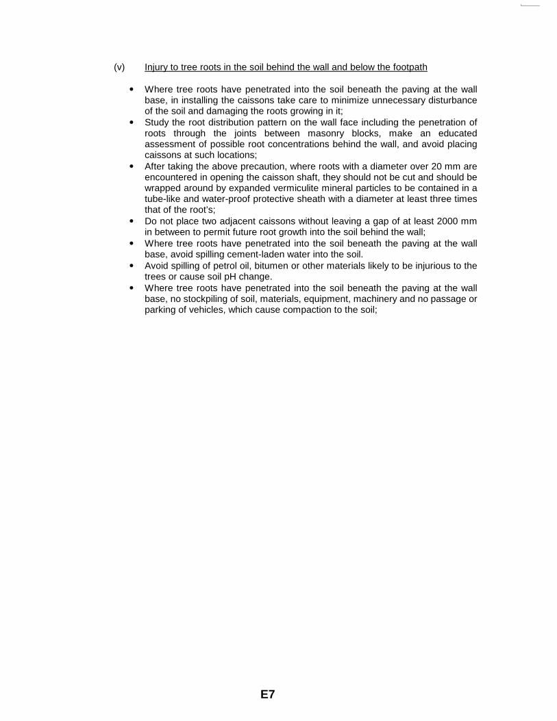
E7
(v) Injury to tree roots in the soil behind the wall and below the footpath • Where tree roots have penetrated into the soil beneath the paving at the wall
base, in installing the caissons take care to minimize unnecessary disturbance of the soil and damaging the roots growing in it;
• Study the root distribution pattern on the wall face including the penetration of roots through the joints between masonry blocks, make an educated assessment of possible root concentrations behind the wall, and avoid placing caissons at such locations;
• After taking the above precaution, where roots with a diameter over 20 mm are encountered in opening the caisson shaft, they should not be cut and should be wrapped around by expanded vermiculite mineral particles to be contained in a tube-like and water-proof protective sheath with a diameter at least three times that of the root’s;
• Do not place two adjacent caissons without leaving a gap of at least 2000 mm in between to permit future root growth into the soil behind the wall;
• Where tree roots have penetrated into the soil beneath the paving at the wall base, avoid spilling cement-laden water into the soil.
• Avoid spilling of petrol oil, bitumen or other materials likely to be injurious to the trees or cause soil pH change.
• Where tree roots have penetrated into the soil beneath the paving at the wall base, no stockpiling of soil, materials, equipment, machinery and no passage or parking of vehicles, which cause compaction to the soil;

- 147 -
APPENDIX F

F1

F2


GEO PUBLICATIONS AND ORDERING INFORMATION
土力工程處刊物及訂購資料
A selected list of major GEO publications is given in the next page. An up-to-date full list of GEO publications can be found at the CEDD Website http://www.cedd.gov.hk on the Internet under “Publications”. Abstracts for the documents can also be found at the same website. Technical Guidance Notes are published on the CEDD Website from time to time to provide updates to GEO publications prior to their next revision.
部份土力工程處的主要刊物目錄刊載於下頁。而詳盡及最新的
土力工程處刊物目錄,則登載於土木工程拓展署的互聯網網頁
http://www.cedd.gov.hk 的“刊物”版面之內。刊物的摘要及更新
刊物內容的工程技術指引,亦可在這個網址找到。
Copies of GEO publications (except geological maps and other
publications which are free of charge) can be purchased either
by:
讀者可採用以下方法購買土力工程處刊物(地質圖及免費刊物
除外):
Writing to Publications Sales Section, Information Services Department, Room 402, 4th Floor, Murray Building, Garden Road, Central, Hong Kong. Fax: (852) 2598 7482
書面訂購
香港中環花園道
美利大廈4樓402室
政府新聞處
刊物銷售組
傳真: (852) 2598 7482
or 或 Calling the Publications Sales Section of Information Services
Department (ISD) at (852) 2537 1910 Visiting the online Government Bookstore at
http:// www.bookstore.gov.hk Downloading the order form from the ISD website at
http://www.isd.gov.hk and submitting the order online or by fax to (852) 2523 7195
Placing order with ISD by e-mail at [email protected]
致電政府新聞處刊物銷售小組訂購 (電話:(852) 2537 1910)
進入網上「政府書店」選購,網址為
http://www.bookstore.gov.hk 透過政府新聞處的網站 (http://www.isd.gov.hk) 於網上遞交
訂購表格,或將表格傳真至刊物銷售小組 (傳真:(852) 2523
7195)
以電郵方式訂購 (電郵地址:[email protected])
1:100 000, 1:20 000 and 1:5 000 geological maps can be
purchased from:
讀者可於下列地點購買1:100 000、1:20 000及1:5 000地質圖:
Map Publications Centre/HK, Survey & Mapping Office, Lands Department, 23th Floor, North Point Government Offices, 333 Java Road, North Point, Hong Kong. Tel: (852) 2231 3187 Fax: (852) 2116 0774
香港北角渣華道333號
北角政府合署23樓
地政總署測繪處
電話: (852) 2231 3187
傳真: (852) 2116 0774
Requests for copies of Geological Survey Sheet Reports and
other publications which are free of charge should be directed to:
如欲索取地質調查報告及其他免費刊物,請致函:
For Geological Survey Sheet Reports which are free of charge: Chief Geotechnical Engineer/Planning, (Attn: Hong Kong Geological Survey Section) Geotechnical Engineering Office, Civil Engineering and Development Department, Civil Engineering and Development Building, 101 Princess Margaret Road, Homantin, Kowloon, Hong Kong. Tel: (852) 2762 5380 Fax: (852) 2714 0247 E-mail: [email protected]
免費地質調查報告:
香港九龍何文田公主道101號
土木工程拓展署大樓
土木工程拓展署
土力工程處
規劃部總土力工程師
(請交:香港地質調查組)
電話: (852) 2762 5380
傳真: (852) 2714 0247
電子郵件: [email protected]
For other publications which are free of charge: Chief Geotechnical Engineer/Standards and Testing, Geotechnical Engineering Office, Civil Engineering and Development Department, Civil Engineering and Development Building, 101 Princess Margaret Road, Homantin, Kowloon, Hong Kong. Tel: (852) 2762 5346 Fax: (852) 2714 0275 E-mail: thomashui @cedd.gov.hk
其他免費刊物:
香港九龍何文田公主道101號
土木工程拓展署大樓
土木工程拓展署
土力工程處
標準及測試部總土力工程師
電話: (852) 2762 5346
傳真: (852) 2714 0275
電子郵件: [email protected]

MAJOR GEOTECHNICAL ENGINEERING OFFICE PUBLICATIONS
土力工程處之主要刊物
GEOTECHNICAL MANUALS
Geotechnical Manual for Slopes, 2nd Edition (1984), 300 p. (English Version), (Reprinted, 2000).
斜坡岩土工程手冊(1998),308頁(1984年英文版的中文譯本)。
Highway Slope Manual (2000), 114 p. GEOGUIDES
Geoguide 1 Guide to Retaining Wall Design, 2nd Edition (1993), 258 p. (Reprinted, 2007).
Geoguide 2 Guide to Site Investigation (1987), 359 p. (Reprinted, 2000).
Geoguide 3 Guide to Rock and Soil Descriptions (1988), 186 p. (Reprinted, 2000).
Geoguide 4 Guide to Cavern Engineering (1992), 148 p. (Reprinted, 1998).
Geoguide 5 Guide to Slope Maintenance, 3rd Edition (2003), 132 p. (English Version).
岩土指南第五冊 斜坡維修指南,第三版(2003),120頁(中文版)。
Geoguide 6 Guide to Reinforced Fill Structure and Slope Design (2002), 236 p.
Geoguide 7 Guide to Soil Nail Design and Construction (2008), 97 p. GEOSPECS
Geospec 1 Model Specification for Prestressed Ground Anchors, 2nd Edition (1989), 164 p. (Reprinted, 1997).
Geospec 3 Model Specification for Soil Testing (2001), 340 p. GEO PUBLICATIONS
GCO Publication No. 1/90
Review of Design Methods for Excavations (1990), 187 p. (Reprinted, 2002).
GEO Publication No. 1/93
Review of Granular and Geotextile Filters (1993), 141 p.
GEO Publication No. 1/2000
Technical Guidelines on Landscape Treatment and Bio-engineering for Man-made Slopes and Retaining Walls (2000), 146 p.
GEO Publication No. 1/2006
Foundation Design and Construction (2006), 376 p.
GEO Publication No. 1/2007
Engineering Geological Practice in Hong Kong (2007), 278 p.
GEO Publication No. 1/2009
Prescriptive Measures for Man-Made Slopes and Retaining Walls (2009), 76 p.
GEOLOGICAL PUBLICATIONS
The Quaternary Geology of Hong Kong, by J.A. Fyfe, R. Shaw, S.D.G. Campbell, K.W. Lai & P.A. Kirk (2000), 210 p. plus 6 maps.
The Pre-Quaternary Geology of Hong Kong, by R.J. Sewell, S.D.G. Campbell, C.J.N. Fletcher, K.W. Lai & P.A. Kirk (2000), 181 p. plus 4 maps. TECHNICAL GUIDANCE NOTES
TGN 1 Technical Guidance Documents