study on mathematical model of solar thermal parabolic
TRANSCRIPT

~ 47 ~
ISSN Print: 2394-7500
ISSN Online: 2394-5869
Impact Factor: 5.2
IJAR 2020; 6(5): 47-51
www.allresearchjournal.com
Received: 14-03-2020
Accepted: 19-04-2020
Dr. Manoj Kumar Sinha
Department of Physics,
Butwal Multiple Campus,
Tribhuvan University, Nepal
Corresponding Author:
Dr. Manoj Kumar Sinha
Department of Physics,
Butwal Multiple Campus,
Tribhuvan University, Nepal
Study on mathematical model of solar thermal
parabolic
Dr. Manoj Kumar Sinha
Abstract
The conceptual design of the concentrating solar power plant (CSPP) includes selection and sizing of
solar field, power generation cycle, types of working fluids, sizing of the power block, etc. The
conceptual design is based on a mathematical modeling of the CSPP. In the present studies, solar
thermal system, a turbine is integrated with 1.2 kW generators, and steam is produced by flow loop
energized by solar parabolic trough concentrators. One of the most significant factors for the successful
conceptual design of a CSPP is a precise determination of the transient solar radiation over the day and
the season. Accordingly, in-situ measurements of the direct normal irradiance (DNI) has been carried
out and used as input to the mathematical model.
Keywords: Study, mathematical, solar thermal, parabolic, CSPP, DNI
Introduction Thermal performance of solar thermal power plant trough collector inside a Solar Energy
Generating Systems plant was examined by Odeh et al. [1]. A design was presented by Hirsch
along with Eck [2] of a phase separation system for DSG PTC field. A comparison was made
between analysis of PTCs molten salt as heat transfer fluids, steam/water, and making use of
oil. Giostri et al. [3] made comparison between different technologies of a solar field with
regards to energy production annually as well as performance at design conditions.
In recent times, Desai et al. [4] presented a technique in order to find the most favorable
design of radiation for concentrating solar powerplant exclusive of thermal storage as well as
hybridization. The aim of present study is to examine the conceptual design and make
prediction of performance of the solar thermal power plant by making use of DSG inside a
parabolic trough solar field.
Fig 1: PTC based Solar
International Journal of Applied Research 2020; 6(5): 47-51
~ 48 ~
International Journal of Applied Research http://www.allresearchjournal.com
Formulation The size of the solar power generation plant using a
parabolic trough collector field is selected to be 1.2 kW. As
shown in Figure-1 illustrates the proposed solar power plant
established. Following are the specifications of the proposed
system:
The capacity of the plant is 1.2 kW.
The composition of Collector receiver tubes includes a
selective outer layer and cover glass made up of
evacuated space amid to minimize the heat loss.
The solar field is made from parabolic trough collectors
which have its alignment in the direction of the axis in
the north to south and having a tracking system in the
direction of the axis in the east to west direction in
order to the trace Incident radiation in day time.
The steam turbine is kind of condensing with pressure
of 0.1 bar.
Solar field consists of 5 modules. Every collector has
three pipes each having the size 2.135 meters in length.
Circulation water pumps with 6 bar pressure and min
having a flow rate of 0.009 kg/s.
Table-1 shows specifications along with dimensions of the
collector. To calculate the heat gain for the steam generation
with a total output power 1.2Kw. The steam pressure at
supply is at 5.2 bars and 200 ˚C and the condenser pressure
is 0.1 bar. Figure 1 displays collectors with a turbine for
electricity generation and a Rankine cycle of steam
generator,
Table 1: Specifications of solar collector.
Mathematical Modeling The mathematical model of the system is proposed in this
particular system. The analysis of energy of parabolic
through solar collector in this segment is laying its
foundation on the equations stated in the references [5, 6] The
first thing proposed is model of solar system. After that the
equations for performance evaluation for whole system is
proposed. An assumption is made that the status of system is
fixed. The variations in pressure are ignored apart from
pressure in the turbines as well as pumps. The definition of
vital rate of energy from the collector is given as:
Qgain = mCL.(h7–h6) = .I.Ap (1)
= 0–UL.
I
T (2)
T=Tm–Ta (3)
Here m(CL) denotes the rate of mass flow rate of steam
passing from Collector unit is kg/s, I= direct normal
irradiance. cos∅ is direct normal incidence radiation on the
reflector (W/m2), AP denotes aperture area of the collector
unit is m2, Tm = (T6 + T7)/2, is the average temperature unit:
˚C, Ta is ambient temperature unit: ˚C, and UL is loss co-
efficient based on aperture area unit is W/m2.K. If the work
input Feed Water Pump (F.W.P) and Recirculation Water
Pump (RC.W.P) and heat losses through piping are ignored
then:
𝑄𝑔𝑎𝑖𝑛 =. (ℎ7−ℎ6=) 𝑚 .(ℎ1 −ℎ3) (4)
From Equations. (1) and (4):
𝑚. (ℎ1−ℎ3) = ƞ.𝐼.𝐴𝑝 (5)
It must be kept in mind that the rate of PTC inlet mass flow
will normally stay firm throughout the operation,
consequently, the difference of dryness factor and the
average temperature will differ at the part load. The
difference of temperature can be evaluated by ignoring the
pump work and supposing the design point outlet dryness
fraction of PTC field at point 7. By keeping inlet pressure
and enthalpy at point 6 the value of PTC field inlet
temperature could be found out.
ℎ6=(1−𝑥7).ℎ8+ 𝑥7.ℎ3 (6)
It should be known here that hi and Ti represents the
temperature along with enthalpy at i-th state point. 0 is
optical efficiency which is defined as:

~ 49 ~
International Journal of Applied Research http://www.allresearchjournal.com
0= 𝜌𝑐 𝛾 𝜏 𝛼 𝐾𝛾 (7)
𝜌𝑐, γ, τ, α and Kγ are the reflectance of the mirror, intercept
factor, transmittance of the glass cover, absorbance of the
receiver, and incidence angle modifier, and their values are
mentioned in Table-1. The definition of aperture area is
given as:
𝐴𝑝=(𝑤−𝐷𝑐𝑜)𝐿 (8)
Where Dco, L, and ware collector module receiver cover
outer diameter, length along with width. The definition of
solar collector heat loss coefficient between receiver and
ambient is given as:
𝑈𝐿 = 1
,.,
1
)(
crrcarcac
r
hhh
A (9)
The definition of radiation heat coefficient between the
cover and ambient is given as:
ℎ𝑟,= 𝜀𝐶𝑣 𝜎 (𝑇𝑐+ 𝑇𝑎)(𝑇𝑐
2 +𝑇𝑎2) (10)
Here, denotes emittance of the cover and Stefane-Boltzmann
is represented by σ. The definition of the radiation heat
coefficient between the receiver and the cover is given as:
ℎ𝑟,=
12
22
,
11
11
))((
FA
A
TTTT
CvC
r
r
r
acavrC
(11)
Here εr denotes emittance of the receiver and the subscript
‘av’ is represents average. The definition of convection heat
loss coefficient between the cover and ambient is given as:
ℎ𝑐,=
oc
air
D
Nuk
.
(12)
Where Nudenotes Nusselt number and Kair represents
thermal conductivity of the air. The subscript r is the
receiver. Calculation of temperature of the cover can be
carried out by this equation:
𝑇𝑐=
r
CCarCaCCrr
r
CCarCaCarCrr
A
Ahhh
A
ATohhTh
)(
)(
,,,
,,,,
(13)
The definition of the amount of the solar radiation that
shines upon the collector, considered as heat into the system
is given as:
𝑄𝑠𝑜𝑙𝑎𝑟 = 𝑚𝑐𝑙.(ℎ7−ℎ6) + 𝑚.(ℎ1−ℎ9) (14)
The performance equations of entire system are given next.
The definition of power produced by the steam turbine is
given as:
𝑊𝑠𝑡= 𝑚 ̇(ℎ1−ℎ2) (15)
Here h denotes enthalpy and subscript st refers to steam.
The definition of net power of the steam Rankine cycle is
given as:
𝑊𝑐𝑦𝑐= 𝑔𝑊𝑠𝑡− (𝑊𝐹.𝑊.𝑃+ 𝑊𝑅𝑐.𝑃.𝑊) (16)
Here WF.W.P denotes power needed for the feed water pump
and WRc.P.W is power for the water recirculation pump;
definition of both is given as:
𝑊𝐹.𝑊.𝑃= 𝑚 ̇(ℎ4−ℎ3)= �̇� 𝜗 (𝑃4−𝑃3) (17)
𝑊𝑅𝑐.𝑃.𝑊= 𝑚 ̇(ℎ6−ℎ5)= 𝑚 ̇𝜗 (𝑃6−𝑃5) (18)
The definition of net electrical efficiency for the steam
Rankine cycle system is given as:
𝑒𝑙=
solar
cyc
Q
W (19)
Results and Discussions The entire data that was measured each 10 minutes and
direct normal irradiance (I) was gathered through a device
situated on the solar side area of UTP. A normal day in a
month is chosen to correspond to month according to (15)
criterion of recommended average day of a month. It
collects full solar radiation beginning at the sunrise hour and
having its ending at sunset hour.
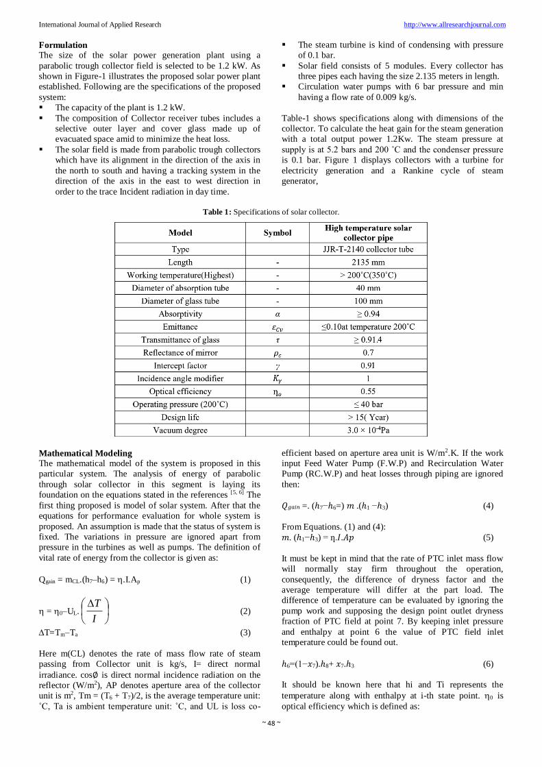
Average of heat gain per hour from PTC is shown in Figure-
2 of six days in each selected month. It is noticed that I is
comparatively high in November out of all months. On the
other hand, the I is the least in September, among these six
months. In September as compared to the month of
November, the decrease observed in I is 34% resulting in a
decreased the heat gain of collector field is 58%. I is
because of the cosine effect which occurs in September and
cloud covers causing lower collector heat gain.
~ 50 ~
International Journal of Applied Research http://www.allresearchjournal.com
Fig 2: Average of hourly heat gain in PTC collector field
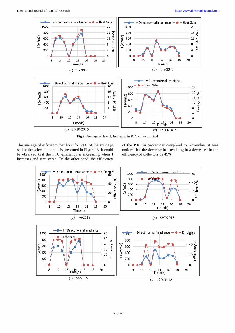
The average of efficiency per hour for PTC of the six days
within the selected months is presented in Figure- 3. It could
be observed that the PTC efficiency is increasing when I
increases and vice versa. On the other hand, the efficiency
of the PTC in September compared to November, it was
noticed that the decrease in I resulting in a decreased in the
efficiency of collectors by 49%.

~ 51 ~
International Journal of Applied Research http://www.allresearchjournal.com
Fig 3: Efficiency in PTC collector field.
Conclusion
A parabolic based thermal collector solar thermal power
plant has been simulated mathematically for conceptual
design calculations. The model was converted to a computer
program within MATLAB environment, which enable
prediction of the required hydrothermal parameters of the
system. The control ideology of plant consists the joint
effect of the solar field under ambient conditions as well as
mentioned solar radiation to account for the constant
generation of power from turbine-generator unit in the hours
of sunshine.
References
1. Odeh SD, Morrison GL, Behnia M. Modelling of
parabolic through direct steam generation solar
collectors. Solar Energy 1998;62(6):395-406.
2. Eck M, Hirsch T. Dynamics and control of parabolic
trough collector loops with direct steam generation’’.
Solar Energy 2007;81:268-279.
3. Giostri A, Binotti M, Astolfi M, Silva P, Macchi E,
Manzolini G. Comparison of different solar plants
based on parabolic trough technology. Solar Energy
2012;86:1208-1221
4. Desai NB, Bandyopadhyay S, Nayak JK, Banerjee R,
Kedare SB. Simulation of 1 M We solar thermal power
plant. In: Proceedings of the ISES Solar World
Congress, Cancun, Mexico 2018.
5. Al-Sulaiman F. Energy and sizing analyses of parabolic
trough solar collector integrated with steam and binary
vapor cycles Energy 2019;58:561-570.
6. Duffie J, Beckman W. Solar engineering of thermal
processes. John Wiley & Sons, Inc 2016.