study on protective performance of hvdc
DESCRIPTION
http://alpar80:[email protected]/login.html?TRANSCRIPT
Study on Protective Performance of HVDC Transmission Line Protection With Different Types
of Line Fault
Han Kunlun School of Electric Power
South China University of Technology Guangzhou, China [email protected]
Cai Zexiang School of Electric Power
South China University of Technology Guangzhou, China
Liu Yang School of Electric Power
South China University of Technology Guangzhou, China
Abstract—HVDC line protection system is composed of traveling wave protection as the main protection, under voltage protection and differential protection as the backup protection. The responses of the HVDC line protection criterion are not same at different fault situations, and it also makes the operation characteristics of the line protection quite different. In this paper, based on the EMTDC simulation platform and an actual HVDC power transmission system and its protection system, the changes of voltage and current of the HVDC line are measured, and the influences of fault location, fault resistance and the external disturbance to the HVDC line protection are also analyzed in detail. At the same time, the relation between the rejecting act of the protection and the factors mentioned above are also discussed, and some improvement schemes are also proposed.
Keywords- HVDC Line Fault;Traveling Wave Protection;Under Voltage Protection; Differential Protection; Protective Performance
I. INTRODUCTION The transmission distance of HVDC system is particularly
long, and this makes the probability of HVDC line fault increased greatly. The actual data coming from electric power enterprises show that 50% faults happened in HVDC system belong to HVDC line faults. And this becomes a serious threat to the power system operation safely and steadily [1-3].
The operation of HVDC system is often affected by the AC system and the HVDC control system, and this makes its operation environment more complex. At the same time, the process of HVDC line fault isn’t analyzed clearly and the principles of it are also analyzed deficiently. All of these mentioned above make it difficult to the research of HVDC line protection. The actual operational data also show that the effect of the current HVDC line protection system is limited [1,
2]. So, it is necessary to study in depth the factors which are affecting the operation of HVDC line protection system.
Lots of research has been made about HVDC line protection systems. In [4-7] made a detailed introduction to the configuration and structure of the HVDC line protection system. In [8-10], the responses of HVDC line protection system during a line fault are analyzed by the simulation of the
typical accident cases. And in [11, 12], some defects of HVDC line protection system are pointed out on the basic of introducing its realization principles, and a new wavelet transformation protection method is discussed.
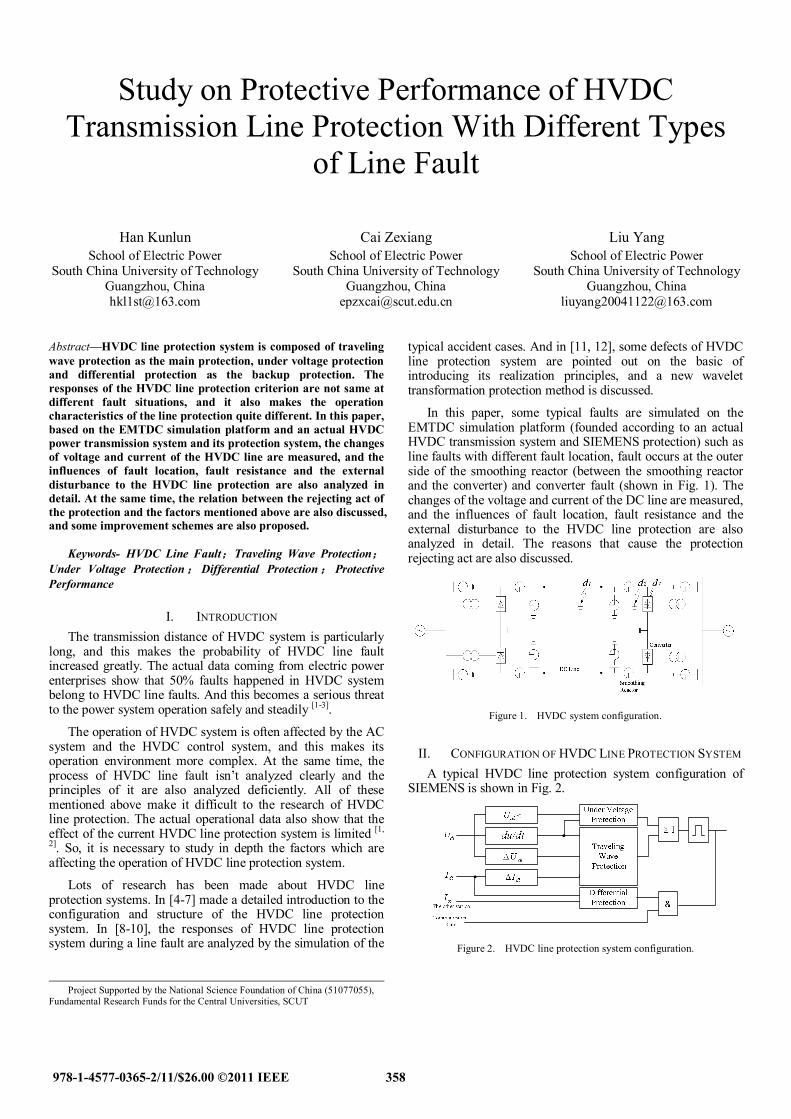
In this paper, some typical faults are simulated on the EMTDC simulation platform (founded according to an actual HVDC transmission system and SIEMENS protection) such as line faults with different fault location, fault occurs at the outer side of the smoothing reactor (between the smoothing reactor and the converter) and converter fault (shown in Fig. 1). The changes of the voltage and current of the DC line are measured, and the influences of fault location, fault resistance and the external disturbance to the HVDC line protection are also analyzed in detail. The reasons that cause the protection rejecting act are also discussed.
Figure 1. HVDC system configuration.
II. CONFIGURATION OF HVDC LINE PROTECTION SYSTEM A typical HVDC line protection system configuration of
SIEMENS is shown in Fig. 2.
Figure 2. HVDC line protection system configuration.
Project Supported by the National Science Foundation of China (51077055), Fundamental Research Funds for the Central Universities, SCUT
978-1-4577-0365-2/11/$26.00 ©2011 IEEE 358

The protection system is mainly composed of three parts: traveling wave protection, under voltage protection and differential protection. Three are three suits of the protection systems like this equipped in each converter station and all of them are the same. When at least two suits of the protection systems act at the same time, a line fault is proved to occur, and this is called “choose two from three” mode.
III. PROTECTIVE PERFORMANCE OF TRAVELING WAVE PROTECTION
When line fault occurs, the voltage and current wave traveling through the transmission line contains plenty of fault information, and the information is extracted by traveling wave protection system. Traveling wave protection is designed to work as the main protection of HVDC line. The criteria of traveling wave protection are as follows:
)(..4.0),(..15.0..4.0
..175.0
inverteratuprectifieratupiupU
updtdu
dl
dl
(1)
A. Traveling Wave Protection Performance to Fault Location Traveling wave protection detects the voltage change rate
du/dt and the voltage change amplitude Udl at the same time. And if the two kinds of criterion exceed their settings, the current change amplitude Idl is detected. If the current criterion also exceeds its setting, the traveling wave protection will act at once. Fig. 3 gives the responses of the voltage and current at rectifier side with different fault location.
1.0000 1.0010 1.0020 1.0030 1.0040 1.0050 1.0060 1.0070 1.0080 1.0090 1.0100
-0.10
0.00 0.10
0.20 0.30
0.40 0.50 0.60
0.70 0.80
0.90 1 2 3
4
.).(
upU
dl
(sec)Time
1.0000 1.0010 1.0020 1.0030 1.0040 1.0050 1.0060 1.0070 1.0080 1.0090 1.0100
-0.10
0.00
0.10
0.20
0.30
0.40
0.50
0.60
0.70
1
2
34
.).
(/
updt
du
(sec)Time
Figure 3. Operation performense of traveling wave protection with different fault location.
Fig. 3 shows changes of the voltage change rate du/dt and the voltage change amplitude Udl with different fault location: at the beginning (curve1), at the middle (curve2), at the end (curve3) and the external (curve4). We can see that both the voltage change rate du/dt and the voltage change amplitude Udl can exceed their settings when a line fault occurs at any point of the DC line, and the response time they need is from 0.2ms to 3ms after the fault occurs. Considered the traveling wave transmits through the transmission line needs some time, the farther the distance from the fault point to the place where the protection equipment installed, the more time it needs to exceed its setting. So traveling wave protection is designed to protect the whole HVDC transmission line. To external fault (between the smoothing reactor and the converter) and converter fault, traveling wave needs to through DC equipments such as smoothing reactor and DC filter, the voltage change rate du/dt is further reduced and it can’t exceed its setting, so traveling wave protection accordingly doesn’t act.
B. Traveling Wave Protection Performance to Fault Resistance Fault Resistance is always exist in an actual HVDC line
fault, and its effect to the operation performance of HVDC line protection is obviously. And some traveling wave protection rejecting act accidents happened in China HVDC system has proved it. Fig. 4 shows the change of the voltage and current at rectifier side with different fault resistance.
1.0000 1.0050 1.0100
-0.20
0.00
0.20
0.40
0.60
0.80
1
32
.).
(up
Udl
(sec)Time
1.0000 1.0050 1.0100
-0.100
-0.050
0.000
0.050
0.100
0.150
0.200
0.250
12
3
.).(
/up
dtdu
(sec)Time
Figure 4. Operation performense of traveling wave protection with different fault resistance.
From Fig. 4 we can see that with the increase of fault resistance (50Ω, curve1; 150Ω, curve2; 250Ω, curve3), the voltage change rate du/dt and the voltage change amplitude Udl becomes lower and lower, and the effect to du/dt is greater than it to Udl. When the fault resistance exceeds a critical value, the du/dt will not reach its setting, and then the
359

rejecting act of the traveling wave protection appears. To the traveling wave protection installed at rectifier side, the longer the distance of fault location from it, the lower the critical value is.
IV. PROTECTIVE PERFORMANCE OF UUNDER VVOLTAGE PROTECTION
Under voltage protection is designed to work as the backup of traveling wave protection and its criteria are as follows:
..25.0
..175.0
upU
updtdu
dl
(2)
Under voltage protection is composed of two criteria, the voltage change rate du/dt and the low voltage Udl. The voltage change rate du/dt and its setting are the same as them in the traveling wave protection, and its operation signal will be keep 20ms here. The Udl is another criterion of the under voltage protection and its setting is very low. Besides these, a voltage blocking signal is also joined to the protection. The low voltage Udl and the voltage blocking signal work together can avoid the malfunction during the transient period. When the traveling wave protection is quit or it is under the state of rejecting act, the under voltage protection will act with the delay of 50ms and it will work as backup protection.
Because of the voltage change rate du/dt in the traveling wave protection and in the under voltage protection is the same, a limitation appeared that when the traveling wave protection rejecting act because of the high fault resistance, the under voltage protection will also rejecting act due to the same reason and its backup function disappeared.
0.950 1.000 1.050 1.100 1.150 1.200 1.250
0.00
0.20
0.40
0.60
0.80
1.00
1.20
321
.).(
upU
dl
(sec)Time
Figure 5. Line voltage with different fault resistance.
Fig. 5 shows the line voltage responses to the faults with different fault resistance (50Ω, curve1; 150Ω, curve2; 250Ω, curve3). All the faults occur at 1s, and the duration time is 60ms. After the faults occur, the degree of line voltage drop is not the same with different fault resistance, but the absolute value of all line voltage can drop under 0.25 p.u. (at rectifier) to make the low voltage criterion exceed its setting, only the response time is obviously slower than that of du/dt (0.2-3ms). So, whether the under voltage protection act correctly is mainly determined by the voltage change rate du/dt. When traveling wave protection rejecting act due to high fault resistance, under voltage protection will also not act with the same reason. This
reduces the reliability of under voltage protection as a backup protection.
V. PROTECTIVE PERFORMANCE OF DIFFERENTAIL PROTECTION
Differential protection is designed to work as the backup protection of traveling wave protection and under voltage protection, and its criteria are as follows:
..05.0 upII osdl
Differential protection, which is the backup protection of the traveling wave protection and the under voltage protection, has the function relatively simple, is designed to detect those faults that the other protections can not response. Its criterion is the differential current between rectifier and inverter. The protection also needs some blocking signals to avoid its malfunction and as a backup protection, it has a delay of 500ms.
There are four kinds of blocking signals in the protection. Among them, the synchronous transmission failure blocking signal is a special one. The principles of the synchronous transmission failure blocking signal are as follow: using the line current minus its value 65ms before, and if this difference exceeds a certain limit, the differential protection will be blocked for 600ms. When a line fault occurs, if the protection is blocked for 600ms firstly, plus the protection delay of 500ms, the total delay will reach 1.1s. Before the protection act, the HVDC control system has been worked in time. So the protection unable to play its function as it is designed, and this phenomenon is very common in practice.
VI. CONCLUSION Traveling wave protection works as the main protection of
HVDC Transmission line. It is designed to protect the whole HVDC transmission line and it also can distinguish the internal and external faults to the line correctly. As its main criterion, the voltage change rate du/dt is sensitive to the change of fault resistance. To a high fault resistance, the rejecting act of traveling wave protection perhaps occurs.
Under voltage protection is designed as the backup protection of traveling wave protection, and the criterion of voltage change rate is the same with it in traveling wave protection. So, its function of backup is limited to the traveling wave protection.
The differential protection is designed as the backup of traveling wave protection and under voltage protection. Synchronous transmission failure blocking signal is too sensitive, and its delay is too long. In practice operation, its backup function is hardly to realize.
REFERENCES [1] DING Zhao, HAN Weiqiang, “Summary of bipolar operation simulation
of Tian-Guang DC power transmission system,” Power System Technology, vol. 27, pp. 49-54, September 2003.
[2] REN Dayong, “Analysis of bipole block events over the years of Tian-Guang HVDC project. High Voltage Engineering,” vol 32, pp. 173-175, Stember 2006.
360

[3] D.Naidoo, N M Ijumba, “Proceedings of IEEE 2004 International Conference on Power System Technology,” pp. 1327-1332, November 2004.
[4] ZHOU Xiangsheng, LIN Rui, “Analysis of relay action of HVDC line and testing method,” High Voltage Engineering, vol. 32, pp. 33-37, September 2006.
[5] DENG Benfei, “HVDC line protection summary of Tian-Guang project,” Power System Protection and Control, vol. 36, pp. 71-74, October 2008.
[6] ZHU Taoxi, JI Guang, “Introduction of wave front protection in Tian-Guang HVDC transmission system,” Power System Protection and Control, vol. 36, pp. 86-89, November 2008.
[7] YE Meng, CAO Haiyan, MA Guopeng, “Analysis of the line protection for HVDC power transmission systems,” Southern Power System Technology, vol. 2, pp. 43-46, December 2008.
[8] GUO Qi, HAN Weiqiang, HUANG Libin, ZHANG Jianshe, YU Jiang, HUANG Jiayin, “TRDS simulation on evaluation of delay time settings of DC under-voltage protection,” Southern Power System Technology, vol. 3, pp. 32-34, April 2009.
[9] LI Aimin, CAI Zexiang, REN Dayong, LI Xiaohua, “Analysis on the dynamic performance characteristics of HVDC control and protections for the HVDC line faults,” Automation of Electric Power Systems, vol. 33, pp. 72-75, June 2009.
[10] HU Yuyang, HUANG Daochun, “Faults and protection analysis of Gezhouba-Nanqiao DC transmission line,” Automation of Electric Power Systems, vol. 32, pp. 102-107, April 2008.
[11] GAO Ximing, Zhang Peng, HE Zhi, “Analysis on the operation of DC transmission line protection,” Automation of Electric Power Systems, vol. 29, pp. 96-99, July 2005.
[12] AI Lin, CHEN Weihua, “Research on traveling wave protection criterion on HVDC transmission line,” Relay, vol. 31, pp. 41-44, October 2003.
361