study on the method of traction motor load simulation on ... · study on the method of traction...
TRANSCRIPT

Study on the method of traction motor load simulation on railway vehicles
F. Lu, S. Li, L. Xu & Z. Yang School of Electrical Engineering, Beijing Jiaotong University, China
Abstract
Based on the physical model of the motor-wheelset system, the expression of the load torque of traction motor is drawn out. According to the two parts – the damping torque of the load torque and inertia loads – the control method of DC load motor electromagnetic torque is proposed separately. Following the principle that the acceleration time should be the same as the actual time, it indicates how to reduce the traction performance curve to fit the power of the load simulation system in the laboratory. Consulting with the actual parameters of CRH2 EMUs, it simulates and authenticates the system control following the method above. Having controlled the damping load torque on 3.5kW hardware platform, the results show the agreement of performance of simulated vehicles and the actual performance curve. This indicates that the method can accurately and exactly simulate the traction motor load. Keywords: load simulation, traction motor, damping load, inertial load, torque control.
1 Introduction
Traction motor load simulation is a method used to obtain the experimental data in the laboratory without experiments on the actual vehicle, by which we can do analysis and research on a traction motor’s characteristic and the control method of the propulsion system. It overcomes the shortcomings of actual-vehicle experiments, such as the high cost, low feasibility, difficulty in changing the condition outside the vehicle and the long cycle of a complete test. By imitating the different kinds of load of the traction motor in different conditions, the key physical quantities’ change can be observed in the corresponding conditions, even under the affection of some certain disturbance. These are important
www.witpress.com, ISSN 1743-3509 (on-line) WIT Transactions on The Built Environment, Vol 114, © 2010 WIT Press
Computers in Railways XII 233
doi:10.2495/CR100231
parameters to research on the vehicle characteristic and control method of the propulsion system. The traction motor load simulation technology is indispensably used in many subjects referring to the propulsion system, such as deciding the power of machines and converters, giving out the method of traction motor torque control, slip, slide and re-adhesion control, inhibiting the fluctuation of the power grid voltage, and research on the affection of harmonic current in the DC circuit.
2 Quality of the load torque
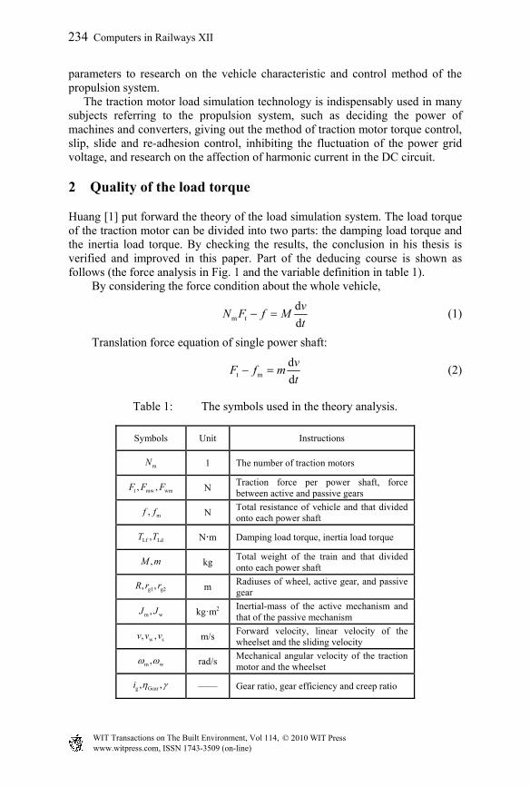
Huang [1] put forward the theory of the load simulation system. The load torque of the traction motor can be divided into two parts: the damping load torque and the inertia load torque. By checking the results, the conclusion in his thesis is verified and improved in this paper. Part of the deducing course is shown as follows (the force analysis in Fig. 1 and the variable definition in table 1).
By considering the force condition about the whole vehicle,
m t
d
d
vN F f M
t (1)
Translation force equation of single power shaft:
t m
d
d
vF f m
t (2)
Table 1: The symbols used in the theory analysis.
Symbols Unit Instructions
mN 1 The number of traction motors
t mw wm, ,F F F N Traction force per power shaft, force between active and passive gears
m,f f N Total resistance of vehicle and that divided onto each power shaft
Lf Ld,T T Nm Damping load torque, inertia load torque
,M m kg Total weight of the train and that divided onto each power shaft
g1 g2, ,R r r m Radiuses of wheel, active gear, and passive gear
m w,J J kg·m2 Inertial-mass of the active mechanism and that of the passive mechanism
w s, ,v v v m/s Forward velocity, linear velocity of the wheelset and the sliding velocity
m w, rad/s Mechanical angular velocity of the traction motor and the wheelset
g Gear, ,i —— Gear ratio, gear efficiency and creep ratio
www.witpress.com, ISSN 1743-3509 (on-line) WIT Transactions on The Built Environment, Vol 114, © 2010 WIT Press
234 Computers in Railways XII

mf
mwF
w sv v v
m m,
ma
,v a
tF
Rg2r
g1r
Wg
mT
w mF Passive Gear
WheelsetActive Gear
Motor Shaft
Figure 1: Force analysis of the wheelset.
Rotation force equation of a power wheelset:
wmw g2 t w
d
dF r F R J
t
(3)
Coming down to the creep ratio between wheel and rail,
w s w(1 )v v v v R (4)
To the traction motor, the torque equation is established:
mm L m
d
dT T J
t
(5)
Considering about the affection of gear efficiency (traction condition),
L wm g1 mw g1 Gear/T F r F r (6)
Combine the equations (1)-(6), and refer to the power transmission characteristic of the gear:
w m g
g g2 g1
/
/
i
i r r
(7)
It is put forward that
L Lf LdT T T (8)
In the equation,
LfGear m g
RT f
N i (9)
2
w mLd 2 2
Gear m g Gear g
d[ ]( )
d(1 )
JMRT
tN i i
(10)
www.witpress.com, ISSN 1743-3509 (on-line) WIT Transactions on The Built Environment, Vol 114, © 2010 WIT Press
Computers in Railways XII 235

The two expressions separately stand for the damping part and the inertia part of the load torque of traction motor. Eqn. (8) is the expression of the load torque.
J is used to express the equivalent rotating inertial-mass besides that of the traction motor in the system:
2
w2 2
Gear m g Gear g
ˆ(1 )
JMRJ
N i i
(11)
3 Torque control of the traction motor
Like the actual condition during the starting course of the train, the traction torque which is generated by the traction motor is firstly added onto the load simulation system, and it directly gives an effect to the load motor. By obtaining the torque and speed information of the traction motor, the load machine immediately gives out the load torque, which should correctly and rapidly imitate the actual load of the traction motor. So, before the control method of the load machine torque is put forward, it should be sure that the control method of the traction motor torque has been proposed at first. The traction motor characteristic curve of the actual vehicle is given by Zhang [2] and shown in Fig. 2. This paper will take the CRH2 (China Railway High-speed) EMUs as an example to discuss how to reduce the actual traction characteristic curve equivalently so that the curve can be used on the experiment platform with reduced power.
Figure 2: The traction performance curve of CRH2.
www.witpress.com, ISSN 1743-3509 (on-line) WIT Transactions on The Built Environment, Vol 114, © 2010 WIT Press
236 Computers in Railways XII
According to the actual condition and the experimental condition, the torque equations of traction motors are separately established:
mm Lf m
dˆ( ) ( ) ( )d
T v T v J Jt
(12)
mm Lf ad ms
d( ) ( ) ( )
dT v T v J J
t
(13)
In the equation, Jms means the inherent rotating inertia-mass of the experiment platform and Jad shows the inertia-mass which should be added on to the system with some inertia mechanical equipments such as flywheel referred in studies [3–5], or with the inertia load torque generated by the load machine. Jad is called the additional rotating inertia-mass. Traction torque can be expressed in the following form:
bm
b
,( )
/ ,
m nv v vT v
p v v v
(14)
bm
b
,( )
/ ,
m n v v vT v
p v v v
(15)
Setting v = kvv’, Tm(v) = kTTm’(v’), kv is called the velocity zoom ratio, and kT is called the torque zoom ratio. Replace the corresponding symbols in eqn. (14) with them.
bv
vm v T m
bv
v
,
( ) ( )
( / ) / ,
vm nk v v
kT k v k T v
vp k v v
k
(16)
So,
v b
T T vm
v T b
v
,
( )/ ( )
,
nk vmv v
k k kT v
p k k vv
v k
(17)
It can be inferred that T
mm
k , v
T
nkn
k ,
v T
pp
k k , b
bv
vv
k .
The damping load torque can be expressed in the following form:
2Lf ( )T v a bv cv (18)
2Lf ( )T v a b v c v (19)
Solving it with the same zoom ratio, T
aa
k , v
T
kb b
k ,
2v
T
kc c
k .
www.witpress.com, ISSN 1743-3509 (on-line) WIT Transactions on The Built Environment, Vol 114, © 2010 WIT Press
Computers in Railways XII 237

Consulting the equations (12) and (13),
m v m mm Lf ad ms
T
ˆ( ) d d( ) ( ) ( ) ( )
d d
J J kT v T v J J
k t t
(20)
Consequently,
vad m ms
T
ˆ( )k
J J J Jk
(21)
Jad is just the additional rotating inertia-mass, which should be added onto the experiment platform. Fig. 3 shows the original traction characteristic curve and the reduced one with the parameters kv = 3.46, kT = 100. On this condition, the relationship between the actual acceleration and the reduced acceleration is
v
1( ) ( )a v a v
k (22)
For application, the value of the velocity zoom ratio and the torque zoom ratio is decided by the rated electromagnetic torque and the rated speed of the traction motor. The reduced traction torque curve will be made the given torque for the traction motor, and the reduced damping torque curve will be made the given torque for the load motor.
4 Torque control of the load motor
This paper only makes a research on the condition of using a DC motor as the load machine. It tells how to control the torque of DC motor to add the load for the traction motor. It is easier to control the torque of DC machine than that of induction machine, so the way to control DC load motor can provide a reference for controlling AC load motor.
Figure 3: Traction curve before and after being reduced.
www.witpress.com, ISSN 1743-3509 (on-line) WIT Transactions on The Built Environment, Vol 114, © 2010 WIT Press
238 Computers in Railways XII

*aI
aI
aUa a
1
R sLaI
TC LdT
m ( )T n
n ms
1
F K J s
n
( )H s*
LdT
T
1
C
11
1
1 sK
s
eC
Figure 4: Closed loop control system of DC generator.
It may be easily inferred from eqn. (8) that the electromagnetic torque of the load machine opposes that of the traction motor. In addition, it is composed by the damping load torque and the inertia load torque. It is relatively easy to control the DC load machine following the damping load curve, for which in this paper it is selectively discussed how to drive a DC machine imitating the inertia load accurately. In fact, the inertia load torque should not surely be imitated by the electromagnetic torque of a load motor. As what has been referred above, inertial mechanic equipments just like flywheels may apply such an inertial torque as well. Not only that, it could greatly simplify the system control. However, according to eqn. (21), the additional rotating inertia-mass is usually great. The volume and weight of the equipment might be unacceptable for a laboratory platform if all the inertia torque is generated by a flywheel. At the same time, the inertia-mass of flywheels is unchangeable if the simulation conditions are changed. So, such a disadvantage may limit the function of the load simulation platform, and will degrade the flexibility of the experiments based on it. Consequently, it is very important to make a research on the technology of electrical inertia-load simulation. Fig. 4 shows the block diagram of a closed loop control system of DC generator in the complex frequency domain. In the dash dotted square, it is the model of the DC machine. The signal Tm(n) is not only the output torque of the traction motor, but also the load torque of the DC load motor. According to the superposition principle, the forward channel of the inertia controller is analyzed specially. The H(s) is assumed as
n adH
( )1
sH s K J
s
(23)
In it, Kn (2π/60) is the conversion coefficient from the rotor speed to the mechanical angular velocity. In the following sections, it will be put forward that how to choose a suitable value for the time const τH according to the system output response. In spite of the viscous damping coefficient F, the time constant of rotor of the DC generator is made as τe = La / Ra. Then let τ1 = τe. When the value of 1K is
www.witpress.com, ISSN 1743-3509 (on-line) WIT Transactions on The Built Environment, Vol 114, © 2010 WIT Press
Computers in Railways XII 239
large enough, the transfer function of the system can be inferred with the Mason’s gain equation:
H e
2ms msm n ms adH e H e
ms ad ms ad
H
H msn ms ad
ms ad
(1 )(1 )1,
( ) ( ) 1( )
11.
( ) 1
s snJ JT K J J s s s
J J J J
sJK J J s s
J J
(24)
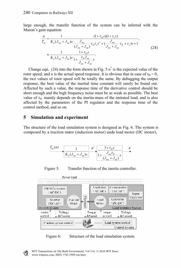
Change eqn. (24) into the form shown in Fig. 5 n* is the expected value of the rotor speed, and n is the actual speed response. It is obvious that in case of τH = 0, the two values of rotor speed will be totally the same. By debugging the output response, the best value of the inertial time constant will surely be found out. Affected by such a value, the response time of the derivative control should be short enough and the high frequency noise must be as weak as possible. The best value of τH mainly depends on the inertia-mass of the imitated load, and is also affected by the parameters of the PI regulator and the response time of the control method, and so on.
5 Simulation and experiment
The structure of the load simulation system is designed as Fig. 6. The system is composed by a traction motor (induction motor) and a load motor (DC motor),
m ( )T n nH
ms H
ms ad
1
1( )
sJ
sJ J
n ms ad
1
( )K J J s
*n
Figure 5: Transfer function of the inertia controller.
Flyw
heel
Figure 6: Structure of the load simulation system.
www.witpress.com, ISSN 1743-3509 (on-line) WIT Transactions on The Built Environment, Vol 114, © 2010 WIT Press
240 Computers in Railways XII

Table 2: Parameters of the actual and experimental motors.
Items CRH2-200 motor AC motor DC generator
Rated power(kW) 300 2.2 3.5
Rated voltage(V) 2000 380 230
Rated current(A) 106 5 15.2
Rated speed(r/min) 4140 1420 1450
Parameters of the equav circuit
Rs 0.144 3.2 275
Lls 0.0014 0.0166 Separate excitation
Rr 0.146 2.2 3.96
Llr 0.0013 0.0166 0.012
Rm 527.7 5.19 CeΦ = 0.165
Lm 0.0328 0.361 CTΦ = 1.58
p 2 2 ——
s
T
1
C
* and Calculator
f s
Figure 7: Simulation model of the load imitation system.
the shafts of which are joined together in order to act the traction torque and its opponent. Parameters of the traction motors on CRH2 EMUs and motors in the laboratory are listed in table 2.
5.1 Simulation of the load imitation system
Based on the theory of load torque control method above, a model of the low power load imitation system of CRH2 traction motor is established with MATLAB/ SIMULINK. The control system is drawn in Fig. 7. Consulting the experimental equation of the basic resistance of vehicle on flat and straight railway, fb = 8.63+0.07295v+0.00112v2(N/t), the total resistance of the vehicle can be calculated out. Substitute the parameters of CRH2 in equations
www.witpress.com, ISSN 1743-3509 (on-line) WIT Transactions on The Built Environment, Vol 114, © 2010 WIT Press
Computers in Railways XII 241
(8)-(10), referring to the rated torque and rated speed of the experimental traction motor shown in table 2. The relationship between the rotor speed of the traction motor and the vehicle velocity is like:
gm
1000 (1 )
60(2πR)n
iv
(25)
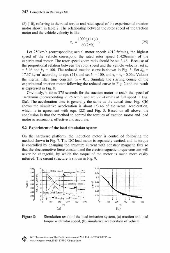
Let 250km/h (corresponding actual motor speed: 4912.5r/min), the highest speed of the vehicle correspond the rated rotor speed (1420r/min) of the experimental motor. The rotor speed zoom ratio should be set 3.46. Because of the proportional relation between the rotor speed and the vehicle velocity, set kv = 3.46 and kT = 100. The reduced traction curve is shown in Fig. 3. Set Jad = 17.37 kg·m2 according to eqn. (21), and set k1 = 100, and τ1 = τe = 0.06s. Valuate the inertial filter time constant τH = 0.1. Simulate the starting course of the experimental traction motor following the reduced curve in Fig. 2 and the result is expressed in Fig. 8. Obviously, it takes 375 seconds for the traction motor to reach the speed of 1420r/min (corresponding v: 250km/h and v’: 72.24km/h) at full speed in Fig. 8(a). The acceleration time is generally the same as the actual time. Fig. 8(b) shows the simulative acceleration is about 1/3.46 of the actual acceleration, which is in agreement with eqn. (22) and Fig. 3. Based on all above, the conclusion is that the method to control the torques of traction motor and load motor is reasonable, effective and accurate.
5.2 Experiment of the load simulation system
On the hardware platform, the induction motor is controlled following the method shown in Fig. 7. The DC load motor is separately excited, and its torque is controlled by changing the armature current with constant magnetic flux so that the electromotive force constant and the electromagnetic torque constant will never be changeful, by which the torque of the motor is much more easily inferred. The circuit structure is shown in Fig. 9.
(a) (b)
Figure 8: Simulation result of the load imitation system, (a) traction and load torque with rotor speed, (b) simulative acceleration of vehicle.
www.witpress.com, ISSN 1743-3509 (on-line) WIT Transactions on The Built Environment, Vol 114, © 2010 WIT Press
242 Computers in Railways XII
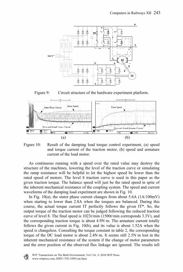
Figure 9: Circuit structure of the hardware experiment platform.
(a) (b)
Figure 10: Result of the damping load torque control experiment, (a) speed and torque current of the traction motor, (b) speed and armature current of the load motor.
As continuous running with a speed over the rated value may destroy the structure of the machines, lowering the level of the traction curve or simulating the ramp resistance will be helpful to let the highest speed be lower than the rated speed of motors. The level 8 traction curve is used in this paper as the given traction torque. The balance speed will just be the rated speed in spite of the inherent mechanical resistance of the coupling system. The speed and current waveforms of the damping load experiment are shown in Fig. 10. In Fig. 10(a), the stator phase current changes from about 5.6A (1A/100mV) when starting to lower than 2.8A when the torques are balanced. During this course, the actual torque current IT perfectly follows the given IT*. So, the output torque of the traction motor can be judged following the reduced traction curve of level 8. The final speed is 1023r/min (1500r/min corresponds 3.3V), and the corresponding traction torque is about 4.9N·m. The armature current totally follows the given current in Fig. 10(b), and its value is about 1.52A when the speed is changeless. Consulting the torque constant in table 2, the corresponding torque of the DC load motor is about 2.4N·m. It seems still 2.5N·m lost in the inherent mechanical resistance of the system if the change of motor parameters and the error position of the observed flux linkage are ignored. The results tell
www.witpress.com, ISSN 1743-3509 (on-line) WIT Transactions on The Built Environment, Vol 114, © 2010 WIT Press
Computers in Railways XII 243

that the control effect of the damping load torque is the same as what is expected.
6 Conclusion
Traction motor load simulation system with double motors and double torque controllers has no closed loop control for the speed, and the speed signal is just one of the input variable which participates in the system control. At the same time, the speed control is one of the most important aims. By dynamic control of the traction torque as well as the load torque, the speed is decided indirectly reflecting the status of the actual vehicle. Although the inertia load is simulated well in the simulation system, limited by the working time of the DSP program codes, the discrete sample time, the highest frequency of the MOSFET and the sample precision of the rotor speed, the hardware platform cannot absolutely satisfy the demands of the control methods. As above, the method of controlling the inertia load has to be improved. What’s more, the paper has given out the additional inertia-mass by eqn. (21), which could be a reference to decide the weights and radiuses of the inertial equipments (such as flywheels). The method of the inertia load torque control by Digital Signal Processor will be discussed in another paper.
Acknowledgements
This paper and its related research are supported by Technology Research and Development Plan of MOR (2009J006-M): Research on the method of DC voltage pulsation suppression in high-speed train propulsion system. We express our sincere appreciation for the substantial support.
References
[1] Huang, Y.P., A study on load simulation of traction motor of railway vehicle, M.S. thesis, Beijing Jiaotong University, Beijing, China, June 2009. (in Chinese)
[2] Zhang, S.G., CRH2 Electricity Multiple Units (China high-speed railway technology: CRH series), China Railway Publishing House: Beijing, 2008. (in Chinese)
[3] Li, Z.S. & Dong C., Actuality on mechanical loads emulation basin on electric powered technology abroad. Machinery, 34(5), pp. 1-3, 2007. (in Chinese)
[4] Padilla, A.J., Asher, M.G. & Sumner, M., Control of an AC Dynamometer for Dynamic Emulation of Mechanical Loads with Stiff and Flexible Shafts. IEEE Transactions on Industrial Electronics, 53(4), pp. 1250-1260, 2006.
[5] Rodic M, Jezernik K & Trlep M., Control Design in Mechatronic Systems Using Dynamic Emulation of Mechanical Loads. Proc. of IEEE ISIE 2005, pp. 1635-1640, 2005.
www.witpress.com, ISSN 1743-3509 (on-line) WIT Transactions on The Built Environment, Vol 114, © 2010 WIT Press
244 Computers in Railways XII