study on the thermal distortion, hardness, and
TRANSCRIPT

Journal of Mechanical Engineering Science and Technology ISSN: 2580-0817
Vol. 3, No. 1, July 2019, pp.18-28 18
DOI: 10.17977/um016v3i12019p018
Study on The Thermal Distortion, Hardness, and Microstructure of St 37
Steel Plate Joined Using FCAW
Maijuansyah1, Yanuar Rohmat Aji Pradana1*, Gaguk Jatisukamto2, and Solichin1
1Mechanical Engineering Department, Universitas Negeri Malang, Jl Semarang 5, Malang, 65145,
Indonesia 2Mechanical Engineering Department, Universitas Jember, Jl Kalimantan 37, Jember, 68121, Indonesia
*Corresponding author: [email protected]
ABSTRACT
This study sets out to investigate the distortion angle, microstructure, and hardness of St 37 steel plate
weld joint produced by FCAW using the welding current of 80, 110, and 140 A. By using flat position,
CO2 and E71T-1 wire were utilized as a shielding gas and electrode filler, respectively. The distortion
angle measurement was done on 3 different locations of the welded sample perpendicular to weld
direction by using bevel protractor. The micro Vickers tests were then applied gradually at the cross-
sectional surface with a distance of 0, 5, 10 and 15 mm from weld centerline using the load of 300 g
for indentation time of 15 s. A series of microstructural observations was subsequently directed on
cross-sectional weld joint regions including base metal, heat-affected zone (HAZ) and weld metal to
investigate the microstructural transformation. From the results, it can be observed that increasing
welding current can reduce the hardness at all indentation regions as well as inducing a higher level of
thermal distortion occurred on a weld joint, especially at HAZ. The microstructural transformation was
also observed at sample welded using various welding current. Both heat input and cooling rate
subjected to the welded sample played an important role to characterize their properties.
Copyright © 2019. Journal of Mechanical Engineering Science and Technology
All rights reserved
Keywords: Hardness, microstructure, thermal distortion, welding current
I. Introduction
Welding becomes an important part on industrial technology growth due to its
important role in metal fabrication and engineering. By involving thermal energy, the
region around weld metal undergo the metallurgical change, residual stress
enhancement, and thermal distortion. To reduce these disadvantage effects, the correct
and optimal of both welding procedure and parameter were highly needed [1]. One of
the widely used welding processes is flux core arc welding (FCAW). This process is
mostly applied on metal fabrication industry because of its advantages, such as higher
deposition rate, less affected on rust, simpler and highly adaptable, less-skilled operator
requirement and higher productivity among other welding processes [2]. Based on a
study conducted by Aloraier et al. (2006), reparation industries applied FCAW instead
of MMAW because of their excellences for years [3].
Welding parameter on FCAW, namely current, voltage, welding speed, polarity,
and protecting gas flow rate turn into an influential factor on the joint characteristics.
The level of penetration was largely determined by the current, voltage, and welding
speed applied during welding, with the deep penetration was resulted by welding using
19 Journal of Mechanical Engineering Science and Technology ISSN: 2580-0817 Vol. 3, No. 1, July 2019, pp.18-28
Maijuansyah et al. (Study on The Thermal Distortion, Hardness and Microstructure of St 37 Welding)
high current and voltage [4]. On the other hand, welding parameters also have a decisive
factor in microstructural change on the weld joint. Therefore, it is possible to find the
different microstructure between weld metal and its base metal due to the different heat
input obtained along the welding direction [5]. Another study was also proved that the
welding current affected the microstructure and hardness distribution along the joint
cross-section [6].
Distortion can be very harmful to the weld quality because it induces inaccurate
joint shape. Therefore, it requires additional reparation cost. On the ship-making
industries in Australia and New Zealand utilizing high strength steel as raw material,
welding distortion becomes a significant problem. The Welding Institute (TWI) revealed
that the cost for repairing welding distortion reached almost 30% of the total production
cost [7]. Based on this problem, the ideal condition screening had been conducted by
researchers to investigate the thermal distortion and find the best parameter to minimize
this phenomenon, where, the suitable parameter combinations were needed to obtain
negligible distortion occurred [8]. Considering the information's above, the effect of heat
input on joint microstructure, hardness, and distortion of St 37 welded by FCAW was
investigated on this study. The different welding current was utilized, representing the
heat input variation.
II. Material and Method
Experiments were conducted by applying several tests on FCAW joint of St 37,
namely distortion angle measurement, microstructural observation, and hardness test.
The base material on this study included 10 mm-thick St 37 structural steel plate with
the alloy composition of 0.063 % C; 0.621 % Mn; 0.031 % P; 0,158 % Si; and 0.039%
Cu. The paired edge of the plate was firstly prepared to form V-shape having the angle
of 60o, the root face of 1.5 mm, and 1 mm gap between each root face. Afterward, the
FCAW (Rillon 350A) was applied on the prepared edge utilizing the filler electrode wire
based on AWS E71T-1 standard having the composition of 0.18% C; 1.75% Mn; 0.90%
Si; 0.03% P; and 0.03% S. The voltage was set at range of 15-25 V. By selecting flat
position, the welding current was varied into 80, 110, and 140 A with the constant
welding speed proportional to the selected current. The active gas of CO2 was also
applied to cover the weld pool along with the process with the constant gas flow rate of
15 LPM.
Distortion measurement was then done on 3 different locations of the sample
perpendicular to weld direction by using bevel protractor as illustrated in Figure 1. The
distortion angle (angular shrinkage), α, was recorded by comparing the lower side of the
unconstrained metal plate to horizontal reference line extended from weld table-
constrained plate interface.
Before microstructural observation and hardness test of the weld joint, the weld
sample was cut into the small piece (55 x 10 x 10 mm) based on DIN 50103. The micro
Vickers indentations were then applied gradually at the cross-sectional surface with the
distance of 0, 5, 10 and 15 mm from weld centerline. This process was done using
Eseway Type Digital Microvickers TH721. During the hardness investigation,
indentation load of 300 g for 15 s was constantly used at all test points.

ISSN: 2580-0817 Journal of Mechanical Engineering Science and Technology 20 Vol. 3, No. 1, July 2019, pp.18-28
Maijuansyah et al. (Study on The Thermal Distortion, Hardness and Microstructure of St 37 Welding)
To evidence the phenomena possibly found on both distortion angle measurement
and hardness test, a microstructural observation was subsequently directed on cross-
sectional weld joint regions including base metal, heat-affected zone (HAZ) and weld
metal. Before capturing the microstructural topography of weld joint, the cross-sectional
surface was firstly polished using sand paper having grit from #150 to #5000. On the
next step, the target area for observation was etched using a mixture of 95% alcohol and
5% HNO3 for 10s. The observation was then conducted with 1400 times of
magnification using a Nikon Japan 59520 Optical Microscope.
Fig. 1. Distortion measurement utilizing (a) angular shrinkage measurement at (b) 3 test
locations perpendicular with the weld direction of the sample.
III. Results and Discussion
Distortion Angle Analysis
Information regarding the distortion angle measurement of as-weld sample using
the different welding currents is described in Figure 2.
80 90 100 110 120 130 140
2.0
2.2
2.4
2.6
2.8
3.0
80 A
110 A
120 A
Dis
tort
ion
An
gle
(o)
Welding Current (A)
Fig. 2. Distortion angle curves of sample welded as a function of welding current representing
a thermal distortion

21 Journal of Mechanical Engineering Science and Technology ISSN: 2580-0817 Vol. 3, No. 1, July 2019, pp.18-28
Maijuansyah et al. (Study on The Thermal Distortion, Hardness and Microstructure of St 37 Welding)
The measurement was conducted at 3 different locations (beginning, middle, and
end of weld) with a constant gap for each test perpendicular with the weld direction and
the results of each measurement and their average values are listed on Table 1. The angle
was considered as the representation of thermal distortion due to the presence of residual
stress at the weld joint.
Table 1. Distortion angle of sample welded using welding current of 80, 110, and 140 A.
Welding Current (A) Distortion Angle (o) Average (o)
Beginning Middle End
80 2 2.13 2.2 2.11
110 2.33 2.43 2.57 2.44
140 2.7 2.83 2.9 2.81
Figure 2 indicates that by using FCAW, the distortion angle becomes larger
proportional with the higher welding current used. This was caused by the enrichment
of residual stress amount, especially at HAZ, as a function of heat input [9]. The heat
input elevation was induced by higher welding temperature resulted from the higher
current. By giving the spontaneous thermal heating, melting, and cooling during
welding, each region of HAZ had received a different amount of heat energy. Therefore,
it experienced various degree of thermal expansion and subsequent contraction by
inhomogeneity cooling rate inducing a non-uniform strain at a particular area. This
remained as residual stress after the weld joint was cooled down into room temperature
in the form of tensile and compression stress [10]. The greater residual stress formation
was generated by the greater degree of heat input. Because the presence of distortion on
weld joint is undesirable, the selection of optimum welding parameters is very important
to minimize this phenomenon without sacrificing the appropriate mechanical properties
[8].
From the Figure 2, the distortion angles are distinct for each measurement point of
similar sample and remain higher at the end line measurement where the highest value
is found at the end line of each sample welded using 80, 110, and 140 A with 2.2; 2.57;
and 2.9o, respectively. This result can be explained by the higher heat input obtained of
the end line in comparison with the two other locations due to the additional heat
transferred from previous weld exposure. Therefore, the welding temperature remained
higher at the end of the welding area. In case of the increase heat input at the end line,
the residual stress-inducing distortion was higher as well [11].
Microstructure Analysis
The temperature of weld metal during welding is approximately 1500 oC. St 37 steel
containing 0.063% C makes this type of steel is included as hypo eutectoid steel (0.008-
0.83% C). Above the crystallization temperature, the phase will transform into austenite
while ferrite and pearlite phases will be found at room temperature [12]. On this study,
in general point of view, the bright- and dark-etched grain was observed indicating the
presence of ferrite and pearlite phases

ISSN: 2580-0817 Journal of Mechanical Engineering Science and Technology 22 Vol. 3, No. 1, July 2019, pp.18-28
Maijuansyah et al. (Study on The Thermal Distortion, Hardness and Microstructure of St 37 Welding)
Fig. 3. Microstructure appearance of joint welded by FCAW using the current of 80 A at
(a) weld metal, (b) HAZ, and (c) base metal with 1400 times magnification.
Fig. 4. Microstructure appearance of joint welded by FCAW using the current of 110 A at
(a) weld metal, (b) HAZ, and (c) base metal with 1400 times magnification.
Figure 3(a) shows the presence of acircular ferrite at weld metal of 80 A sample
indicated by the appearance of dark, needle-like shaped ferrite [13]. This made the
hardness value of weld metal reached 284.1 HV or higher than the raw material (260.7
HV) due to the significant phase transformation occurred in the weld metal.
Furthermore, this phenomenon was also affected by the E71T-1 wire application,
possibly forming a new compositional combination with the base metal, where the wire
material became the dominant composition due to its function as weld filler. On the other
hand, heat input induced by the current of 80 A also played an important role in the

23 Journal of Mechanical Engineering Science and Technology ISSN: 2580-0817 Vol. 3, No. 1, July 2019, pp.18-28
Maijuansyah et al. (Study on The Thermal Distortion, Hardness and Microstructure of St 37 Welding)
microstructural transformation and hardness enhancement on the weld metal. From the
figure, the acircular ferrite was dominant phase compared with the others, working as
an interlocking structure to impede the dislocation movement [14]. Acircular ferrite is
generally formed at around 650oC and possess the higher toughness than other
microstructures [12]. One of the factors affected acircular ferrite formation is the
presence of inclusion caused by oxidation particle inside the melting metal. This could
be occurred due to several aspects, such as base metal composition, electrode, shielding
gas, air-condition, and flux [14].
Fig. 5. Microstructure appearance of joint welded by FCAW using the current of 140
A at (a) weld metal, (b) HAZ, and (c) base metal with 1400 times magnification.
At the weld metal region, the phases transformed using the currents of 110 and 140
A (Figure 4(a) and 5(a)) were the mixture of widmanstatten ferrite and acircular ferrite.
The acircular ferrite amount was lower compared with the 80 A sample because it
substituted into widmanstatten ferrite. The latter phase was formed at 750-650oC [15]
and induced the hardness reduction, to the value of 240.4 and 227.5 HV at samples
welded using 110 and 140 A, respectively. These phenomena can be attributed by the
different level of heat input received for each sample, where the larger grain was formed
if the higher welding temperature was achieved in the weld metal causing lower cooling
rate compared with the lower current.
At HAZ for all current variations (Figure 3(b), 4(b), and 5(b)), the presence of
pearlite was dominant alongside the ferrite phase caused by the growth of pearlite grain
from its base metal at elevated temperature during welding thermal cycle. The hardness
test showed that HAZ provide the higher hardness value at all variations compared with
their base metal counterparts with 262.7; 236.9; and 193.6 HV at sample welded using
80, 110, and 140 A, respectively. By applying higher heat input, the hardness was
observed to be lower at HAZ. It may be caused by excessive grain growth at higher heat
input, consequently reducing its hardness [12][15][16]. During weld metal cooling, the

ISSN: 2580-0817 Journal of Mechanical Engineering Science and Technology 24 Vol. 3, No. 1, July 2019, pp.18-28
Maijuansyah et al. (Study on The Thermal Distortion, Hardness and Microstructure of St 37 Welding)
base metal temperature increased because the base metal acted as a heat sink. Therefore,
a low thermal gradient and cooling rate occurred at high heat input. Thus the larger grain
of pearlite can be formed from austenite [13][15]. Such pearlite size enlargement became
the reason for the hardness reduction.
Less-significant phase transformation induced by thermal cycle effect was found on
the base metal of all current variations where the bright-etching phase, ferrite, and dark-
etched phase, pearlite, were still observed from microstructure image as found on 80 A
sample (Figure 3(c)). However, the relatively large hardness reduction up to 173.2 HV
was detected for sample welded using higher heat input of 140 A at the distance of 15
mm from weld centerline indicating grain coarsening and homogenizing occurred
instead of phase transformation in the microstructural state. It can be explained by the
size development of pre-existing ferrite colony along with the size reduction of pearlite
grain due to high heat input conducted from weld metal, indicating these currents
generated larger HAZ [12]. The size development of 110 and 140 A was relatively
similar, as depicted in Figure 4(c) and 5(c). Generally speaking, the hardness of base
metal showed the lower value compared with HAZ because the pearlite size reduction
during the welding thermal cycle, and the reduction level was proportional with heat
input given [17].
Hardness Analysis
The hardness test was conducted on room temperature at the distance of 0, 5, 10,
and 15 mm from weld centerline using an indentation load of 300 g. The indentation
was taken from these points representing the region of weld metal, HAZ and base metal.
The hardness test results are listed in Table 2, and the hardness curves as a function of
test distance and FCAW welding current are further described in Figure 6.
Table 2. Hardness of sample welded using different current of 80, 110, and 140 A.
Welding Current
(A)
Hardness (HV)
0 mm 5 mm 10 mm 15 mm
80 284.2 262.7 237.8 246.9
110 240.4 236.9 193.1 180.5
140 227.5 195.6 193.7 173.2
Raw material 260.7
The results on Table 2 demonstrates that the welded joint performs different results
in case of hardness compared with the raw material where the hardness of weld metal
and HAZ at 80 A sample have the higher values, but it remains lower at the other points
of all variations. This phenomenon indicates the microstructural evolution after the
welding process, as the current played an important role to characterize the
microstructure and hardness distribution [6].
When the test conducted at weld metal, the significant elevation of hardness was
occurred at sample welded using 80 A compared with that of 110 and 140 A samples.
The compositional difference of E71T-1 filler wire with the base metal varied the
mechanical properties of weld metal with the base counterparts because the wire
dominantly filled the weld bead up to the weld root gap. Due to the higher C and other
alloying elements on the wire, at low heat input, the Cr-carbide was deposited, thus
25 Journal of Mechanical Engineering Science and Technology ISSN: 2580-0817 Vol. 3, No. 1, July 2019, pp.18-28
Maijuansyah et al. (Study on The Thermal Distortion, Hardness and Microstructure of St 37 Welding)
enhance the hardness at weld metal [18]. This property enhancement was also consistent
with a previous study conducted by Katherasan et al. (2012) [19]. Contrary, the hardness
reduction on identical location was found on sample welded using both 110 and 140 A
with 240.4 and 227.5 HV, respectively, caused by the relatively high heat input given
during welding. This parameter induced the microstructural change as depicted in Figure
3(a), 4(a), and 5(a) where the presence of both widmanstatten and lower amount of
acircular ferrite (compared with that found on weld metal of 80 A sample). The
widmanstatten ferrite enrichment had a responsibility of these hardness reductions [13].
0 5 10 15
180
200
220
240
260
280
80 A
110 A
120 A
time : 15 sload : 300 g
Ha
rdn
ess
(H
V)
Distance from weld centerline (mm)
Fig. 6. Hardness curves of welded joint as a function of welding current
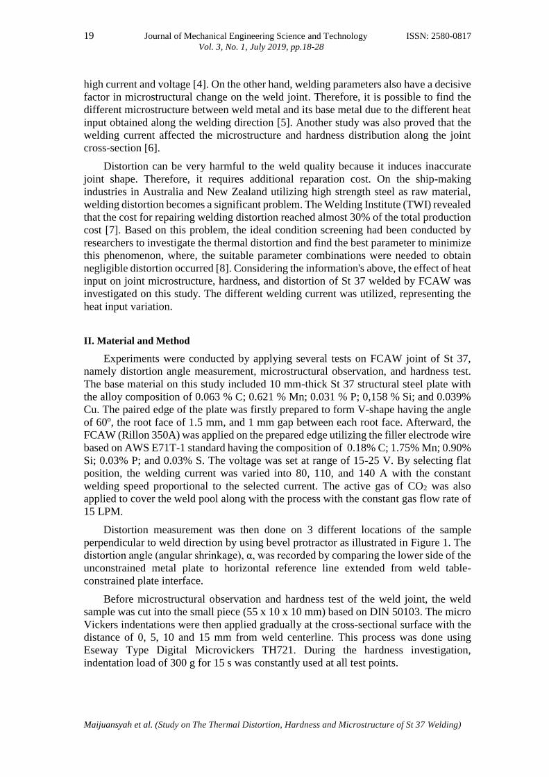
The hardness evolution of HAZ is similar with those on weld metal as illustrated in
Figure 6, where the hardness of HAZ as results of welding using 80 A shows the value
of 262.7 HV, or still higher than the raw material. The HAZ hardening was related to
the high-temperature gradient and cooling rate due to low heat input possibly causing
the grain refining on this region [15][16][20]. As shown in Figure 3(b), the
microstructure of HAZ welded is dominated by small and irregular pearlite grain
inducing the hardness elevation. On the other hand, with the value of 236.9 and 195.6
HV at HAZ of 110 and 140 A sample, the hardness of this region was determined to be
lower than 80 A sample, even the raw material. The grain growth and coarsening of
predominantly ferrite, and a lower amount of pearlite from its base metal by using higher
heat input induced the hardness reduction. By comparing the HAZ microstructure on
both of sample welded using 110 and 140 A, the pearlite acting as dislocation inhibitor
is found to be lower at 110 A sample as shown in Figure 4(b), and 5(b).
On the test taken at the distance of 10 and 15 mm from weld centerline representing
the base metal hardness, it can be seen that no significant microstructural change and
only ferrite and pearlite grain coarsening, or homogenizing, was observed as illustrated
from the Figure 3(c), 4(c) and 5(c). By using low heat input induced by the current of
80 A, the hardness difference between raw material and base metal after welding was
ISSN: 2580-0817 Journal of Mechanical Engineering Science and Technology 26 Vol. 3, No. 1, July 2019, pp.18-28
Maijuansyah et al. (Study on The Thermal Distortion, Hardness and Microstructure of St 37 Welding)
relatively low. However, at higher heat input generated by the currents of 110 and 140
A, the hardness reduction became obvious at the range of 173.2-193.7 HV compared
with raw material (260.7 HV). Although the base metal temperature was not sufficient
to reach recrystallization temperature (A1), the heating at sub-A1 was still able to modify
the microstructure in case of homogenizing, coarsening, and internal stress relieving
with the higher effect can be achieved with the higher temperature/heat input [12]. It is
consistent with the phenomenon occurred where the base metal hardness of 140 A
sample reached the lowest point on 15 mm among all variations with 173.2 HV.
IV. Conclusions
By using FCAW method, St 37 steel plate having the thickness of 10 mm had been
successfully joined involving AWS E71T-1 electrode wire as a filler and CO2 as the
shielding gas. Based on distortion angle measurement, micro Vickers test and
observation by optical microscope on the weld joint using the welding current of 80,
110, and 140 A, the results can be concluded as follows: (1) The distortion angle
becomes larger, proportional with the higher welding current used indicating the
increase of residual stress amount, especially at HAZ, as a function of heat input; (2)
The microstructural evolution was observed on weld metal and HAZ where the weld
metal was dominated by acircular ferrite at sample welded using 80 A, and additional
phase of widmanstatten ferrite was observed on samples welded with higher current.
The ferrite and pearlite grain were found on HAZ, and the amount was varied by welding
current while no significant phase transformation identified on base metal, and (3) The
hardness value was strongly influenced by welding current applied with the higher
hardness curve was achieved by lower current representing lower heat input, where the
highest value was obtained from weld metal of 80 A sample with 284.1 HV. The
hardness was also decreased when the indentation was taken at further location from
weld centerline.
References
[1] Duniawan, A & Sutrimo. “Effect of welding speed and heat input on mechanical
properties of weld metals on SAW welding of ASTM A29 carbon steel”.
Yogyakarta: AKPRIND Yogyakarta, 2010.
[2] Kannan, T & Murugan, N. “Effect of flux cored arc welding process parameters
on duplex stainless steelclad quality”. Journal of Material Processing Technology,
vol.176, pp. 230-239, 2006.
[3] Aloraier, A., Ibrahim, R., Thomson, T. “FCAW process to avoid the use of
PWHT”. International Journal of Pressure Vessel and Piping, vol. 83, pp.394-
398, 2006.
[4] Syarul, I.A., Ibrahima, Amira, A. Ghaliba. “The effect of flux core arc welding
(FCAW) processes on different parameters”. Selangor: Universiti Teknologi Mara
(UiTM), Procedia Engineering, vol. 41, pp. 1497-1501, 2012.

27 Journal of Mechanical Engineering Science and Technology ISSN: 2580-0817 Vol. 3, No. 1, July 2019, pp.18-28
Maijuansyah et al. (Study on The Thermal Distortion, Hardness and Microstructure of St 37 Welding)
[5] R.F. Scott, “Key concept in welding engineering”, Welding Innovation XVI, vol.
1, pp.8-11, 1999.
[6] Priadi, D dan Selvinus. “Study of the effect of weld current on the distribution of
hardness, micro structures, and impact strength on SB 46 low carbon steel”. Jurnal
Sains dan Teknologi EMAS, vol. 17, no. 3, pp.203-212, 2007. (in Indonesian)
[7] Andritsos, F., Prat, J. P., “The Otomation and Integration of Production Processes
in Ship Building”. Joint Research Center, European Commission, 2000.
[8] Venkatesan, M.V., Murugan, N., Prasad, B.M., dan Manickavasagam, A.
“Influence of FCA welding process parameters on distortion of 409M stainless
steel for rail coach building”. Journal of Iron and Steel Research, vol. 20, pp.71–
78, 2013.
[9] Yang, Y.P., Dull, R., Castner, H., Huang, T.D., and Fanguy, D. “Material strenght
effect on weld shinkage and distortion”. Welding Journal, vol. 93, pp. 421-42014.
[10] Rahman, A dan Nasruddin. “Analysis of the effect of residual stress the results of
the welding using a single V groove on AISI 1050 steel”. Journal of Mechanical
Science and Technology, vol. 1, no. 1, pp.1-12. 2013. (in Indonesian).
[11] Wibowo, H., Ilman, M.N., Iswanto, P.T. “Analysis of heat input welding on
distortion, micro structure and mechanical strength of A36 steel”. Jurnal Rekayasa
Mesin, vol. 7, no.1, pp. 5-12, 2016. (in Indonesian).
[12] Kou, S. “Welding Metallurgy”, Second Edition Singapore: John Wiley & Sons,
2003.
[13] Suryana, Pramono, A., Muda, I., and Setiawan, A. “The influence of heat input to
mechanical properties and microstructures of API 5L-X65 steel using submerged
arc welding process”. MATEC Web of Conferences vol. 269, no. 01009, 2019.
[14] Suharno. “Micro structure of C-Mn steel welding results of submerged arc welding
with heat input variations”. Jurnal Teknik Mesin, vol. 10, no.1, pp.40-45, 2008.
(in Indonesian).
[15] Turichin, G., Kuznetsova, M., Pozdnyakova, A., Gook, S., Gumenyuk, A., and
Rethmeier M. “Influence of heat input and preheating on the cooling rate,
microstructure and mechanical properties at the hybrid laser-arc welding of API
5L X80 steel” Procedia CIRP vol. 74, pp.748–751, 2018.
[16] Grajcar, A., Róhanski M., Stano, S., Kowalski, A., and Grzegorczyk, B. “Effect
of heat input on microstructure and hardness distribution of laser welded Si-Al
TRIP-type steel”. Advances in Materials Science and Engineering Vol. 2014,
Article ID 658947, pp.1-8, 2014.
[17] Ovat, F.A., Asuquo, L.O., Anyandi, J.A. “Microstructural effect of electrodes type
on the mechanical behavior of welded steel joint”. Research Journal in
Engineering and Applied Sciences, vol. 1, no.3, pp.171-176, 2012.

ISSN: 2580-0817 Journal of Mechanical Engineering Science and Technology 28 Vol. 3, No. 1, July 2019, pp.18-28
Maijuansyah et al. (Study on The Thermal Distortion, Hardness and Microstructure of St 37 Welding)
[18] Fox, A.G & Evans, G.M. “How non-metalic inclusions containing Ti and Al
nucleate acicular ferrite in SMA weld made on C-Mn steel”. Welding Journal, vol.
75, no.10, pp. 330-339, 1996.
[19] Katherasan, D., Sathiya, P., dan Raja, A. “Shielding gas effects on flux cored arc
welding of AISI 316L (N) austenitic stainless steel joints”. Journal of Welding
Research, vol. 45, pp. 43–51, 2012.
[20] Samir, Y. M. “Investigation on effect of heat input on cooling rate and mechanical
property (hardness) of mild steel weld joint by MMAW process”. International
Journal of Modern Engineering Research, vol. 5, no. 3, pp. 34-41, 2015.