stulz controller communications...
TRANSCRIPT

STULZ Controller
®
Communications Manual
Supplemental Instruction ManualIOM
STULZ E² Controller6000/7000 MIBFieldServer
BACnet IP, BACnet Ethernet, HTTP, SNMP, & Modbus IP
BACnet MS/TP
Modbus RTU
Preface
These set-up procedures supplement the Installation & Operation Manual that is provided with your network communications device.
Notice This document contains information protected by copyright. All rights are reserved. The owner of the equipment for which this manual is written may photocopy the contents of this manual for internal use only. No part of this document may be photocopied, reproduced, or translated into another language for use by anyone other than the owner of the equipment for which this manual is written without the prior written consent of STULZ Air Technology Systems, Inc. (STULZ). This document contains confidential and proprietary information of STULZ Air Technology Systems, Inc. Distributing or photocopying this document for external distribution is in direct violation of U.S. copyright laws and is strictly prohibited without the express written consent of STULZ. Unpublished — rights reserved under the copyright laws of the United States and of other countries. Other brands and tradenames are trademarks of their respective owners. Copyright 2014 by STULZ Air Technology Systems, Inc. Printed in the United States of America. All rights reserved. STULZ Air Technology Systems, Inc. 1572 Tilco Drive Frederick, MD 21704, USA
1
Table of Contents
BACnet MSTP.....................................................................................................................2 BACnet IP/Ethernet/Modbus TCP.....................................................................................10
Modbus RTU......................................................................................................................15 pCOWeb Clock Configuration...........................................................................................16
C6000 MIB.........................................................................................................................17 Field Server.........................................................................................................................20 Flash Memory Life.............................................................................................................23
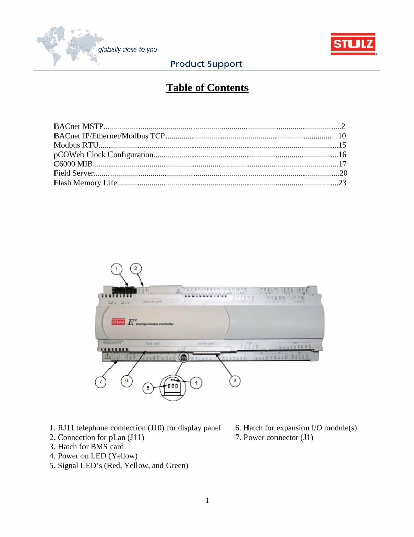
1. RJ11 telephone connection (J10) for display panel 6. Hatch for expansion I/O module(s) 2. Connection for pLan (J11) 7. Power connector (J1) 3. Hatch for BMS card 4. Power on LED (Yellow) 5. Signal LED’s (Red, Yellow, and Green)
2
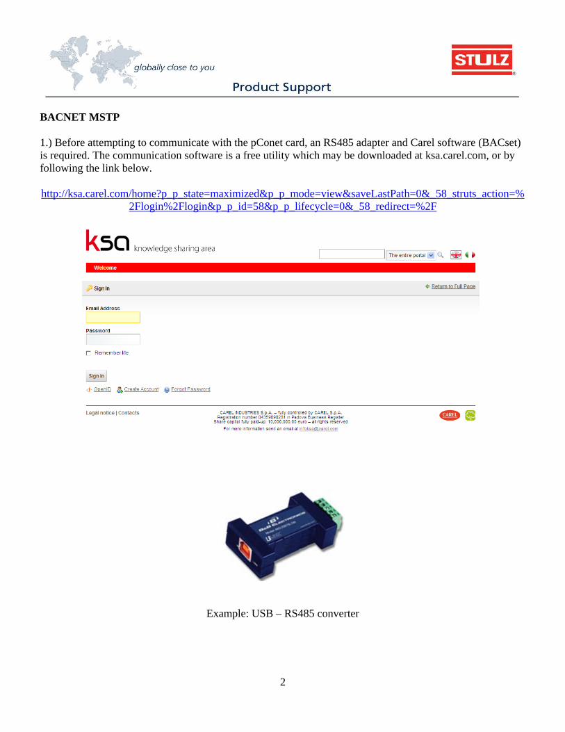
BACNET MSTP 1.) Before attempting to communicate with the pConet card, an RS485 adapter and Carel software (BACset) is required. The communication software is a free utility which may be downloaded at ksa.carel.com, or by following the link below. http://ksa.carel.com/home?p_p_state=maximized&p_p_mode=view&saveLastPath=0&_58_struts_action=%
2Flogin%2Flogin&p_p_id=58&p_p_lifecycle=0&_58_redirect=%2F
Example: USB – RS485 converter
3
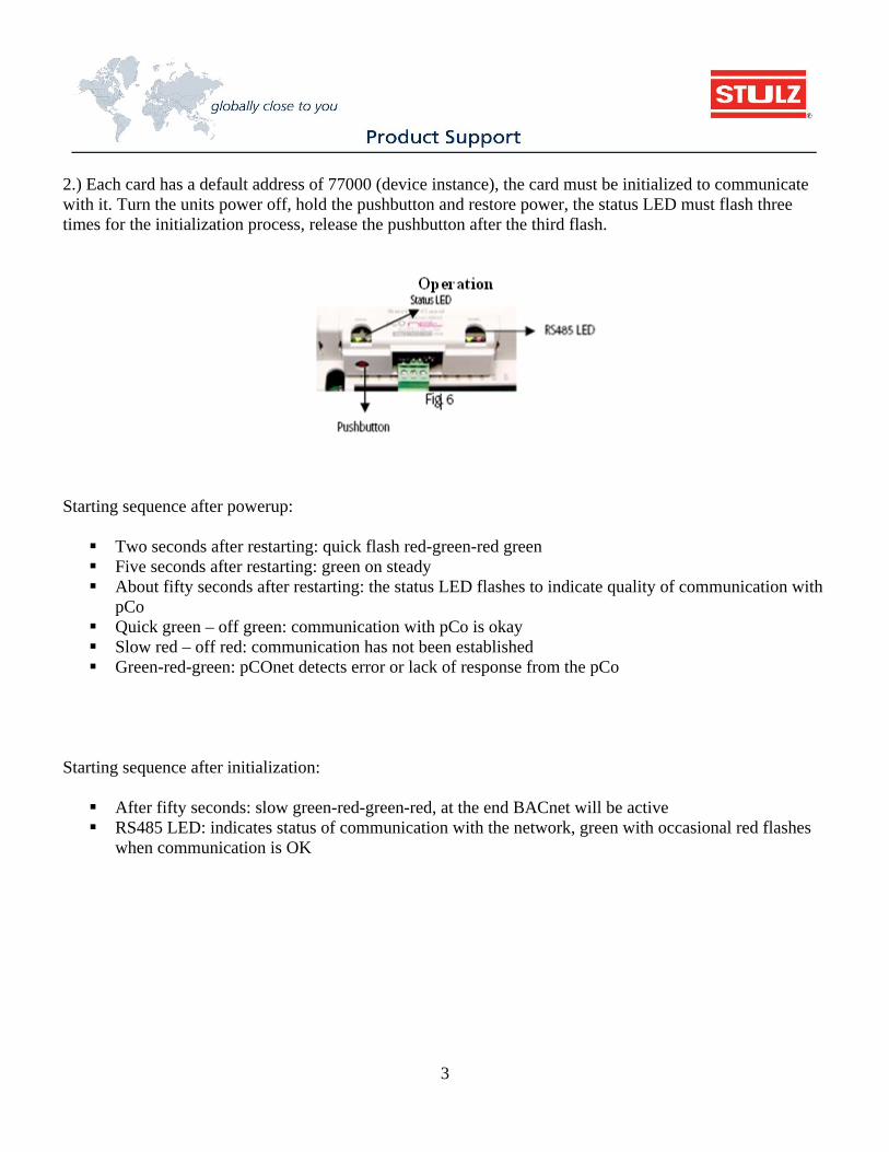
2.) Each card has a default address of 77000 (device instance), the card must be initialized to communicate with it. Turn the units power off, hold the pushbutton and restore power, the status LED must flash three times for the initialization process, release the pushbutton after the third flash.
Starting sequence after powerup: Two seconds after restarting: quick flash red-green-red green Five seconds after restarting: green on steady About fifty seconds after restarting: the status LED flashes to indicate quality of communication with
pCo Quick green – off green: communication with pCo is okay Slow red – off red: communication has not been established Green-red-green: pCOnet detects error or lack of response from the pCo
Starting sequence after initialization: After fifty seconds: slow green-red-green-red, at the end BACnet will be active RS485 LED: indicates status of communication with the network, green with occasional red flashes
when communication is OK
4
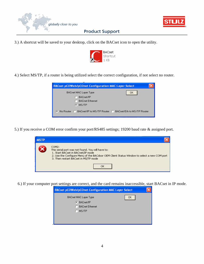
3.) A shortcut will be saved to your desktop, click on the BACset icon to open the utility.
4.) Select MS/TP, if a router is being utilized select the correct configuration, if not select no router.
5.) If you receive a COM error confirm your port/RS485 settings; 19200 baud rate & assigned port.
6.) If your computer port settings are correct, and the card remains inaccessible, start BACset in IP mode.
.
5
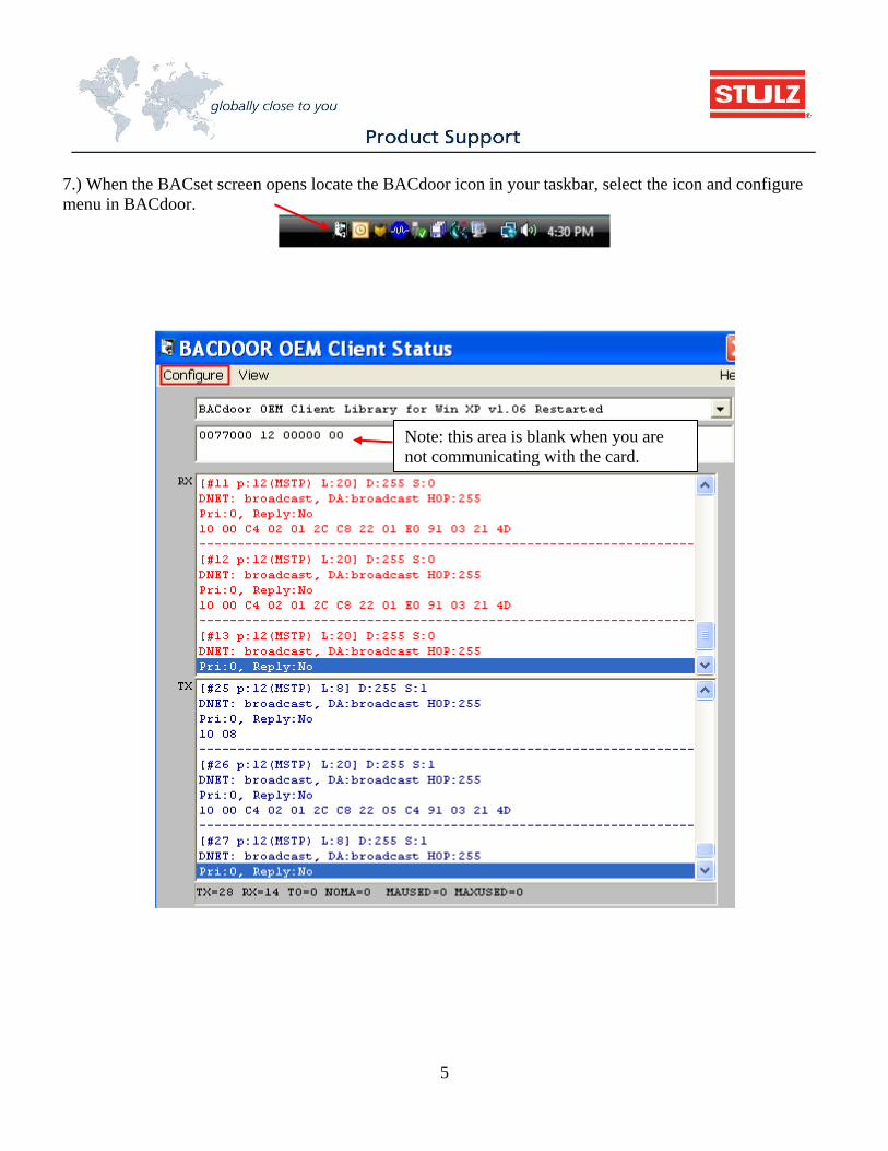
7.) When the BACset screen opens locate the BACdoor icon in your taskbar, select the icon and configure menu in BACdoor.
Note: this area is blank when you are not communicating with the card.
6
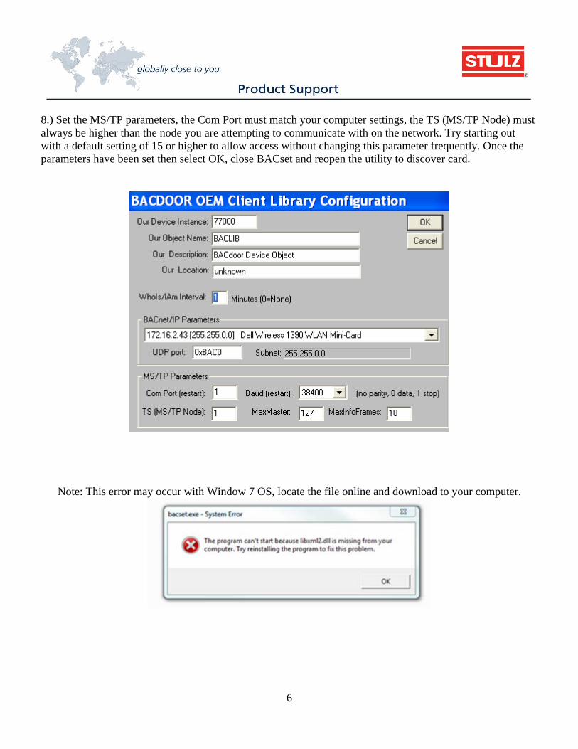
8.) Set the MS/TP parameters, the Com Port must match your computer settings, the TS (MS/TP Node) must always be higher than the node you are attempting to communicate with on the network. Try starting out with a default setting of 15 or higher to allow access without changing this parameter frequently. Once the parameters have been set then select OK, close BACset and reopen the utility to discover card.
Note: This error may occur with Window 7 OS, locate the file online and download to your computer.
7
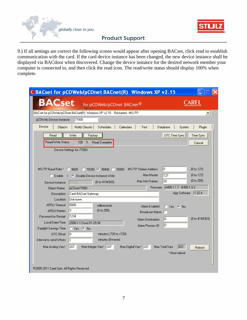
9.) If all settings are correct the following screen would appear after opening BACset, click read to establish communication with the card. If the card device instance has been changed, the new device instance shall be displayed via BACdoor when discovered. Change the device instance for the desired network member your computer is connected to, and then click the read icon. The read/write status should display 100% when complete.
8
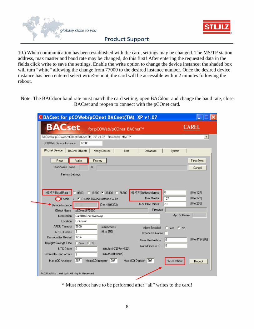
10.) When communication has been established with the card, settings may be changed. The MS/TP station address, max master and baud rate may be changed, do this first! After entering the requested data in the fields click write to save the settings. Enable the write option to change the device instance; the shaded box will turn “white” allowing the change from 77000 to the desired instance number. Once the desired device instance has been entered select write>reboot, the card will be accessible within 2 minutes following the reboot.
Note: The BACdoor baud rate must match the card setting, open BACdoor and change the baud rate, close BACset and reopen to connect with the pCOnet card.
* Must reboot have to be performed after “all” writes to the card!
9
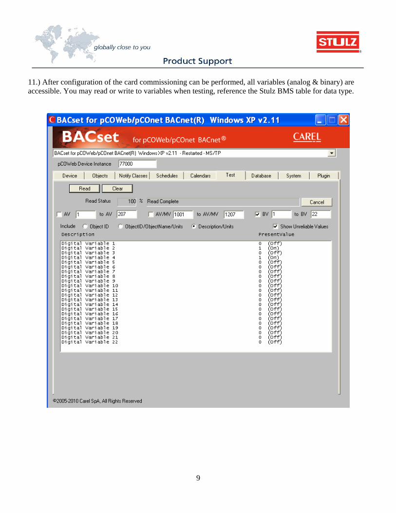
11.) After configuration of the card commissioning can be performed, all variables (analog & binary) are accessible. You may read or write to variables when testing, reference the Stulz BMS table for data type.
10
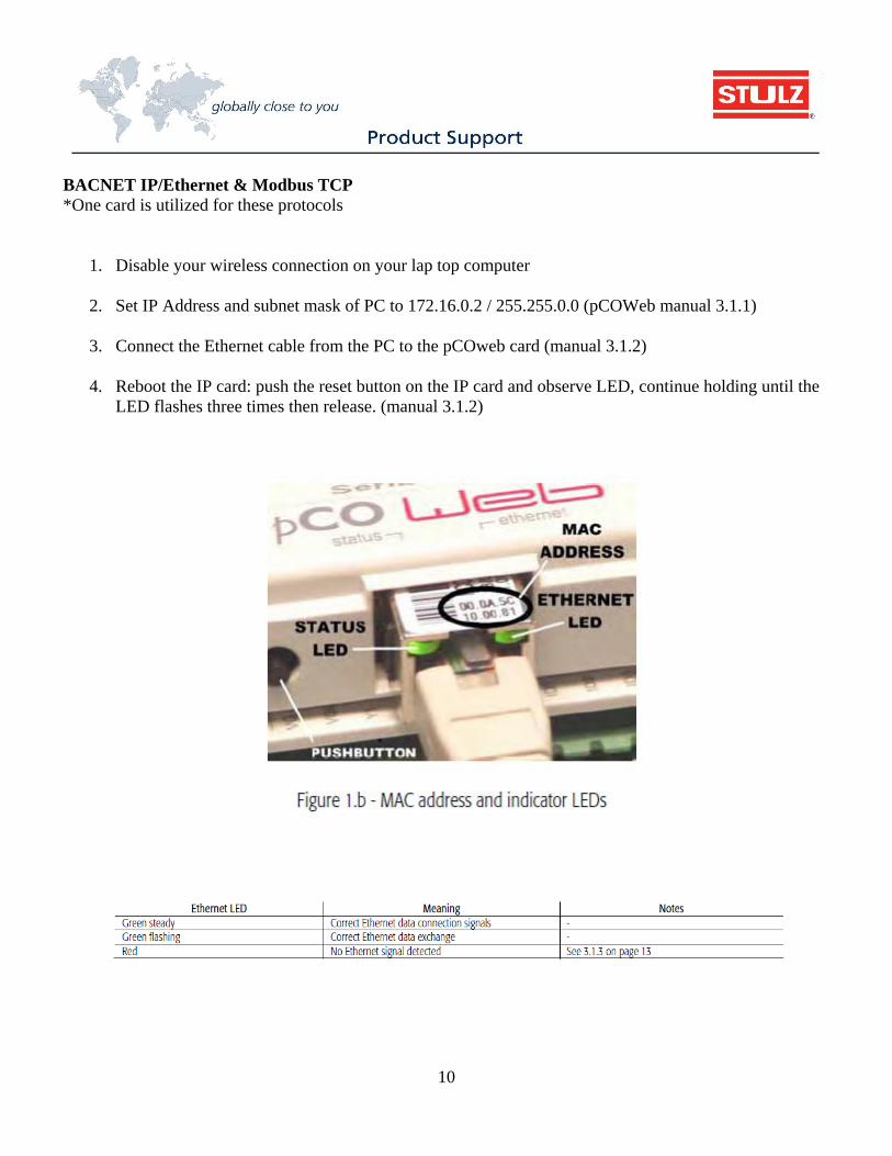
BACNET IP/Ethernet & Modbus TCP *One card is utilized for these protocols
1. Disable your wireless connection on your lap top computer
2. Set IP Address and subnet mask of PC to 172.16.0.2 / 255.255.0.0 (pCOWeb manual 3.1.1)
3. Connect the Ethernet cable from the PC to the pCOweb card (manual 3.1.2)
4. Reboot the IP card: push the reset button on the IP card and observe LED, continue holding until the LED flashes three times then release. (manual 3.1.2)
11
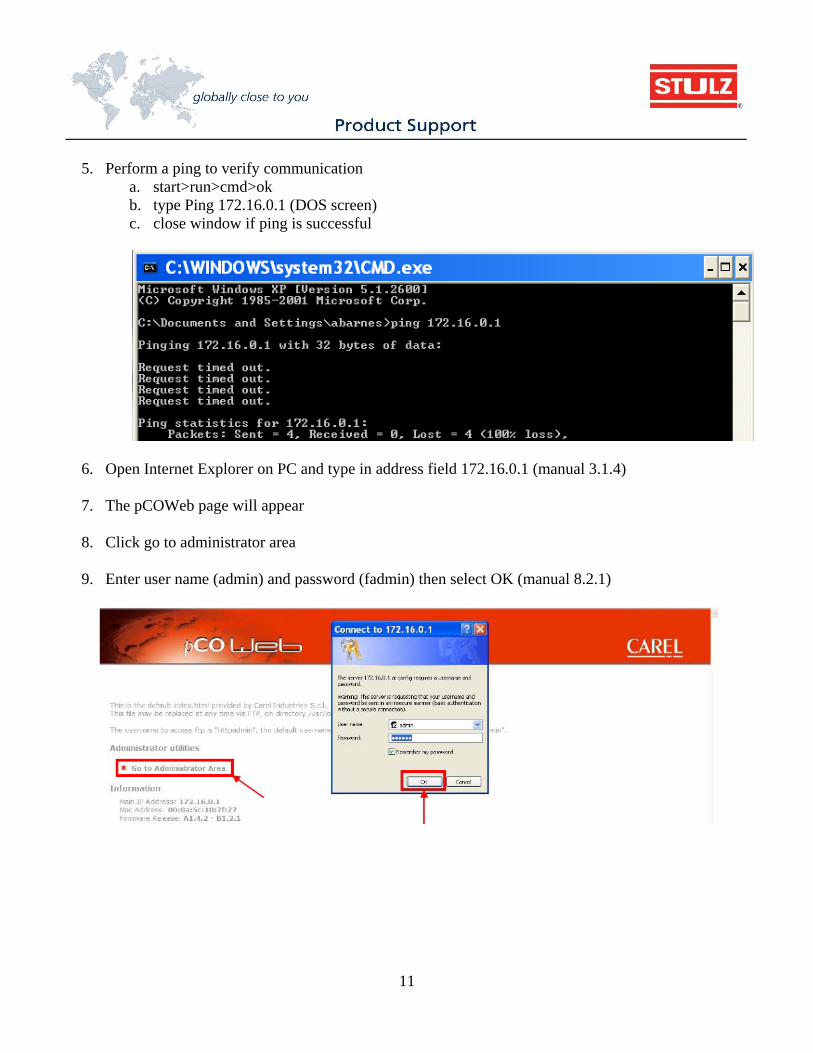
5. Perform a ping to verify communication
a. start>run>cmd>ok b. type Ping 172.16.0.1 (DOS screen) c. close window if ping is successful
6. Open Internet Explorer on PC and type in address field 172.16.0.1 (manual 3.1.4)
7. The pCOWeb page will appear
8. Click go to administrator area
9. Enter user name (admin) and password (fadmin) then select OK (manual 8.2.1)
12
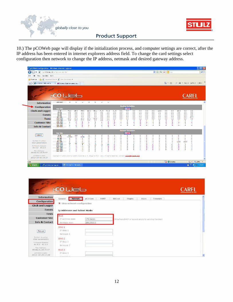
10.) The pCOWeb page will display if the initialization process, and computer settings are correct, after the IP address has been entered in internet explorers address field. To change the card settings select configuration then network to change the IP address, netmask and desired gateway address.
13
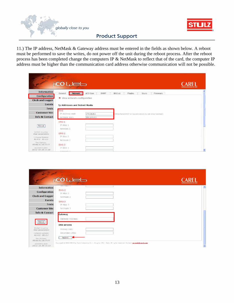
11.) The IP address, NetMask & Gateway address must be entered in the fields as shown below. A reboot must be performed to save the writes, do not power off the unit during the reboot process. After the reboot process has been completed change the computers IP & NetMask to reflect that of the card, the computer IP address must be higher than the communication card address otherwise communication will not be possible.
14
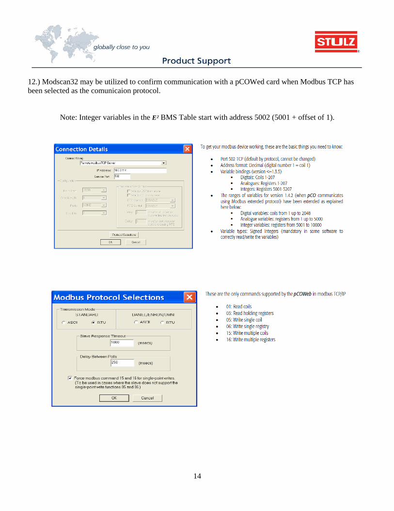
12.) Modscan32 may be utilized to confirm communication with a pCOWed card when Modbus TCP has been selected as the comunicaion protocol.
Note: Integer variables in the E2 BMS Table start with address 5002 (5001 + offset of 1).
15
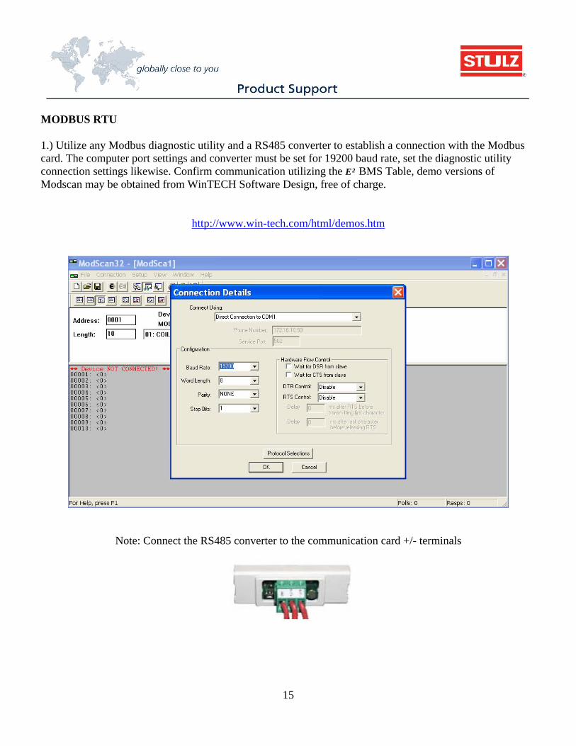
MODBUS RTU 1.) Utilize any Modbus diagnostic utility and a RS485 converter to establish a connection with the Modbus card. The computer port settings and converter must be set for 19200 baud rate, set the diagnostic utility connection settings likewise. Confirm communication utilizing the E2 BMS Table, demo versions of Modscan may be obtained from WinTECH Software Design, free of charge.
http://www.win-tech.com/html/demos.htm
Note: Connect the RS485 converter to the communication card +/- terminals
16
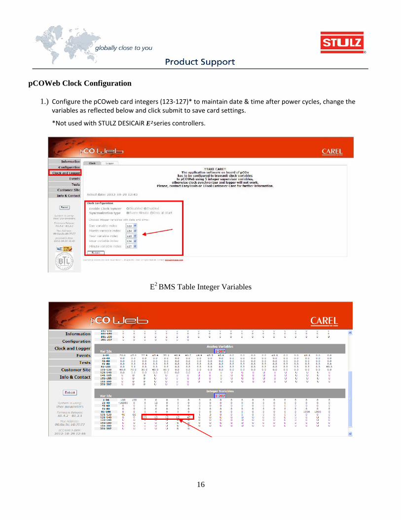
pCOWeb Clock Configuration
1.) Configure the pCOweb card integers (123‐127)* to maintain date & time after power cycles, change the variables as reflected below and click submit to save card settings.
*Not used with STULZ DESICAiR E2series controllers.
E2 BMS Table Integer Variables
17
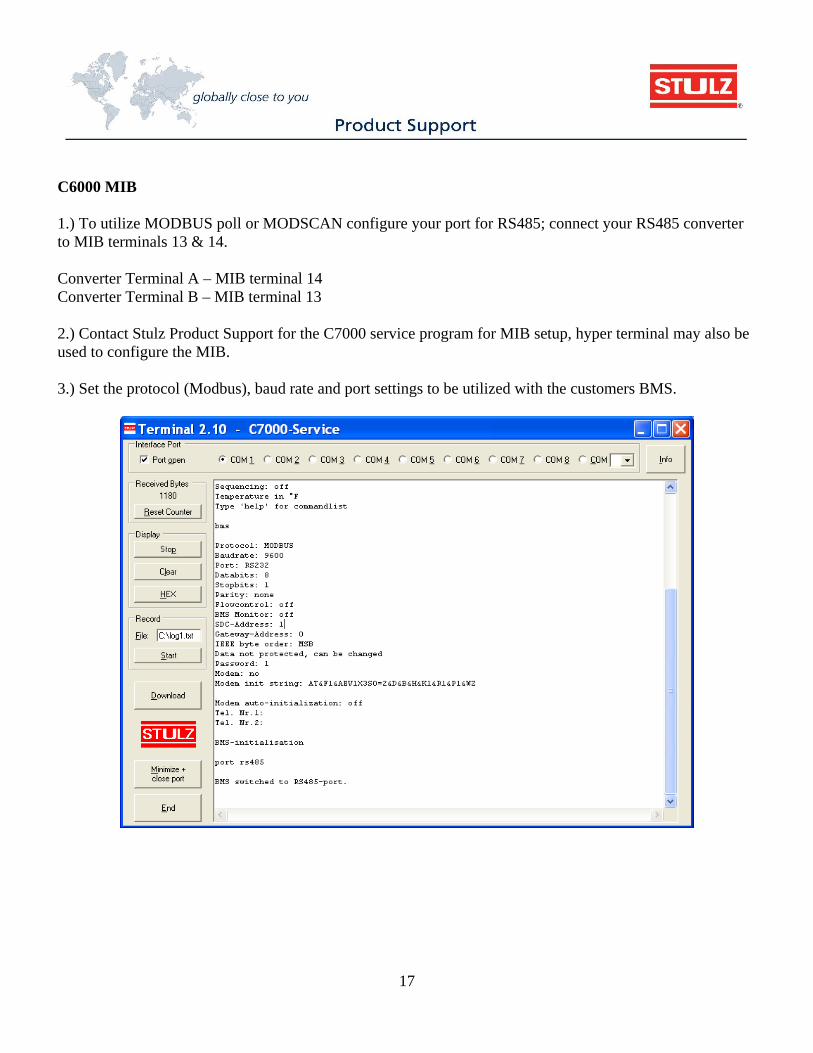
C6000 MIB 1.) To utilize MODBUS poll or MODSCAN configure your port for RS485; connect your RS485 converter to MIB terminals 13 & 14. Converter Terminal A – MIB terminal 14 Converter Terminal B – MIB terminal 13 2.) Contact Stulz Product Support for the C7000 service program for MIB setup, hyper terminal may also be used to configure the MIB. 3.) Set the protocol (Modbus), baud rate and port settings to be utilized with the customers BMS.
18
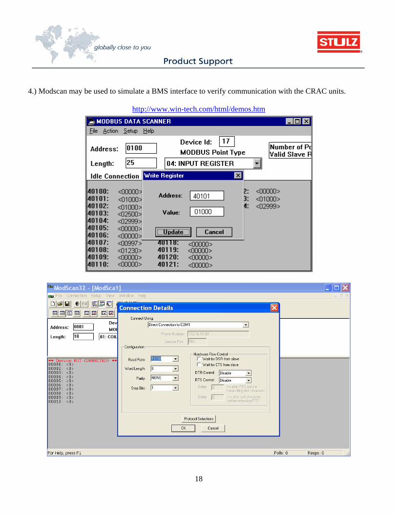
4.) Modscan may be used to simulate a BMS interface to verify communication with the CRAC units.
http://www.win-tech.com/html/demos.htm
19
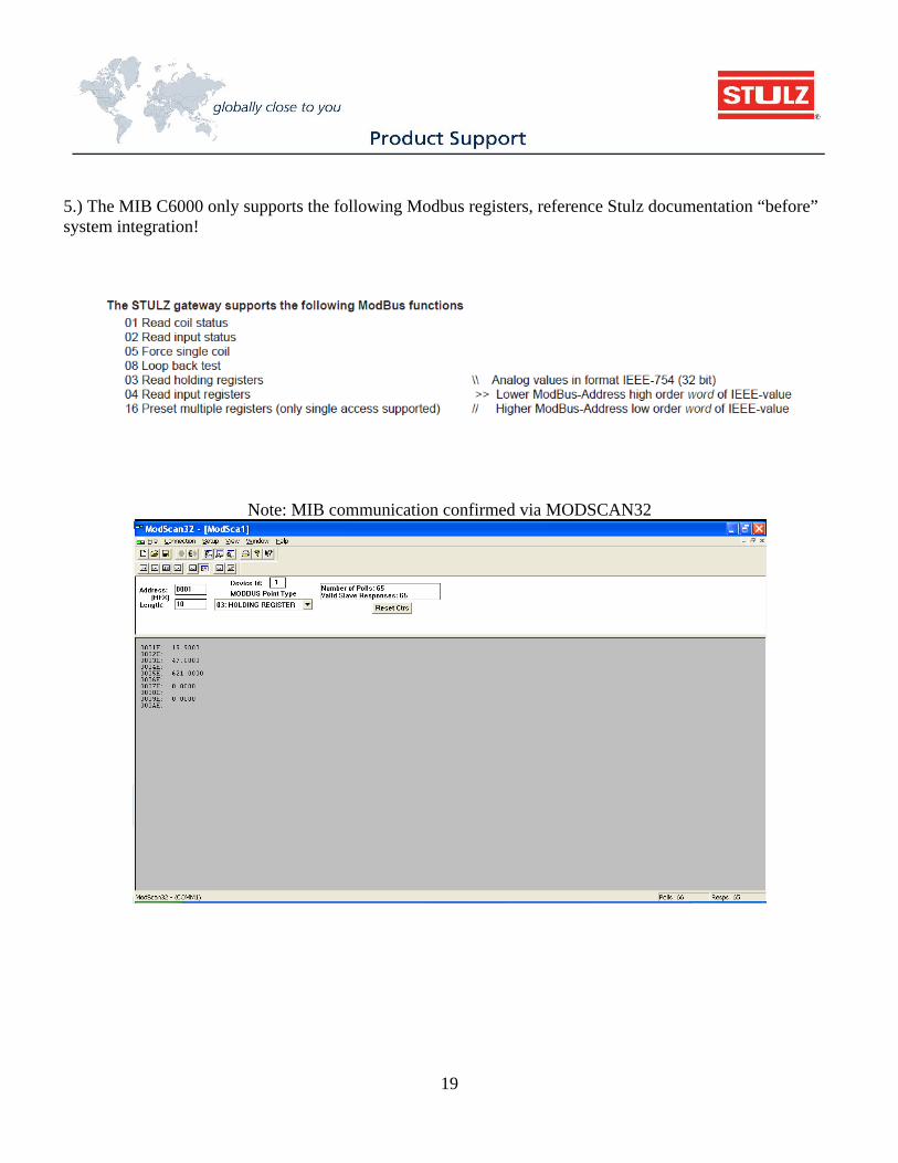
5.) The MIB C6000 only supports the following Modbus registers, reference Stulz documentation “before” system integration!
Note: MIB communication confirmed via MODSCAN32
20
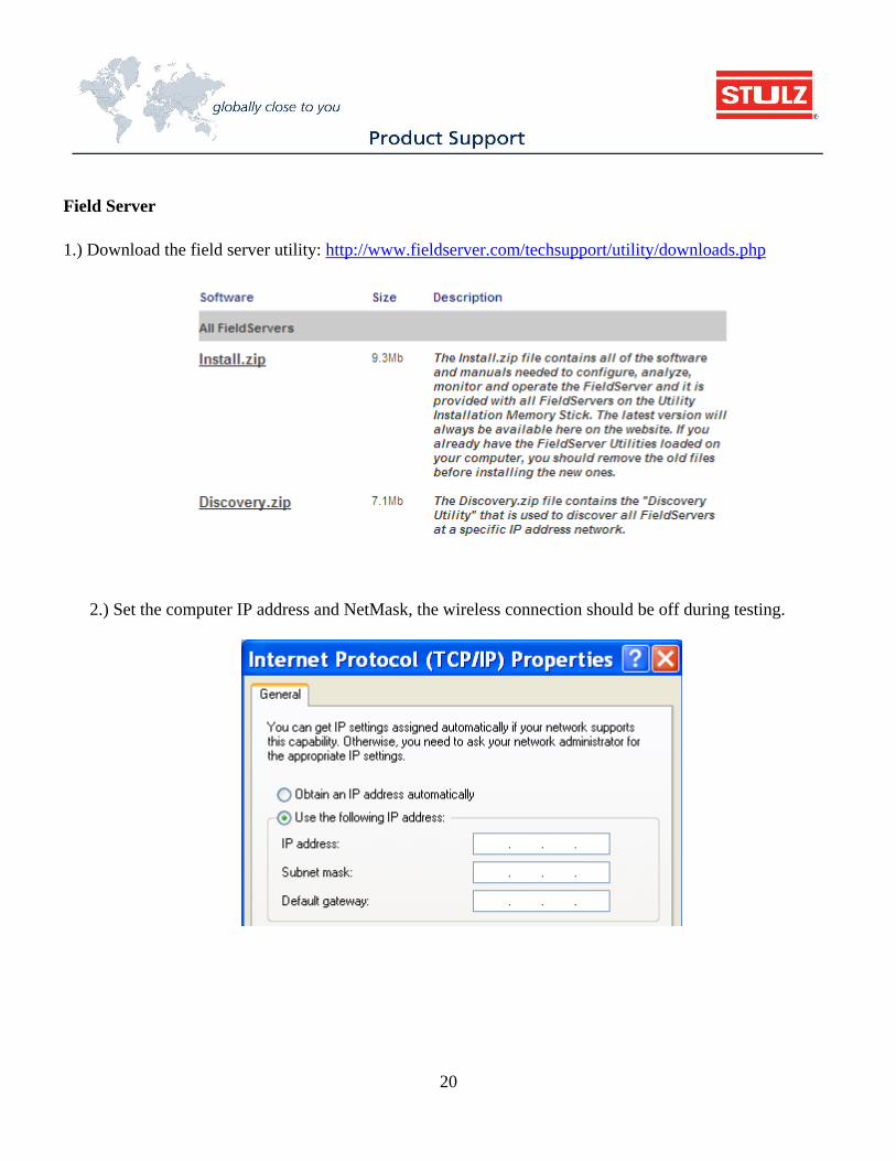
Field Server 1.) Download the field server utility: http://www.fieldserver.com/techsupport/utility/downloads.php
2.) Set the computer IP address and NetMask, the wireless connection should be off during testing.
21
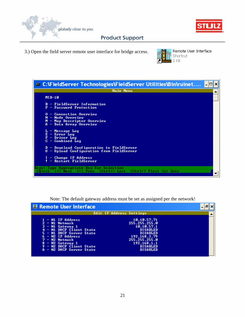
3.) Open the field server remote user interface for bridge access.
Note: The default gateway address must be set as assigned per the network!
22
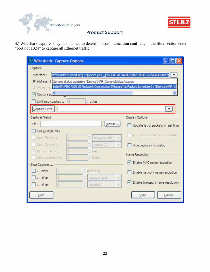
4.) Wireshark captures may be obtained to determine communication conflicts, in the filter section enter “port not 1024” to capture all Ethernet traffic.

23
NOTICE Flash Memory Life No matter how recent the hardware is in a controller, any flash memory has a limited number of write cycles before it fails. A typical number is 1 million cycles (1,000,000) which if someone is writing to every 10 seconds, can be reached rather quickly. The unit will fail in 115 days, i.e. less than 3 months.
60 seconds per minute, 60 minutes per hour = 3600 seconds
Seconds per hour
Write cycle (seconds)
# of writes per hour
# of writes per day
Days to reach 1 million
Years
3600 10 360 8640 115.7 0.3 3600 20 180 4320 231.5 0.6 3600 30 120 2880 347.2 1.0 3600 60 60 1440 694.4 1.9 3600 120 30 720 1388.9 3.8 3600 300 12 288 3472.2 9.5 3600 600 6 144 6944.4 19.0


STULZ CyberRow Chilled Water Series Installation, Operation & Maintenance Manual
(Dec., 2013)
January, 2014OCU0147-
Specifi cations subject to change without notice.
ISO 9001 Quality Management System - Requirements
STULZ Air Technology Systems, Inc.1572 Tilco Drive, Frederick, Maryland 21704
Phone: 301.620.2033, Fax: 301.662.5487E-mail: [email protected]
www.STULZ.com
STULZ mission is to be the premier provider of energy effi cient temperature and humidity control solutions for mission critical applications.
Production Facilities: U.S.A. • Germany • Italy • China • India
®
ISO9001Registered
Quality System