sub-1 ghz embedded sensor to cloud industrial … ghz embedded sensor to cloud industrial internet...
TRANSCRIPT

1TIDUD09–July 2017Submit Documentation Feedback
Copyright © 2017, Texas Instruments Incorporated
Sub-1 GHz Embedded Sensor to Cloud Industrial Internet of Things (IoT)Gateway Reference Design
TI Designs: TIDC-01002Sub-1 GHz Embedded Sensor to Cloud Industrial Internetof Things (IoT) Gateway Reference Design
DescriptionThe TIDC-01002 design demonstrates how to connectsensors to the cloud over a long-range, Sub-1 GHzwireless network, which may be used in industrialsettings, such as building control and asset tracking.This TI Design is powered through a TI SimpleLink™CC3220 processor and SimpleLink ultra-low-power(ULP), Sub-1 GHz CC1310 and CC1350 devices. Thereference design pre-integrates the TI 15.4-Stack partof the SimpleLink CC13x0 software development kit(SDK) and SimpleLink CC3220 SDK, which are part ofthe TI SimpleLink MCU platform, providing a unifiedsoftware experience across TI low-power, wired, andwireless MCUs.
Resources
TIDC-01002 Design FolderCC1310 Product FolderCC1350 Product FolderCC3220 Product Folder
ASK Our E2E Experts
Features• Large Network-to-Cloud Connectivity Enabling
Long Range, Up to 1 km (Line of Sight)• Facilitates Designers’ System Compliance with
IEEE 802.15.4e/g by Using TI 15.4-Stack• Based on TI Tested Hardware Designs Enabling
Quick Time to Market With Out-of-the-Box, Ready-to-Use Demonstration Software
• Implementation Based on Portable OperatingSystem Interface (POSIX), Allows for EasyPortability Across TI Internet ConnectedMicrocontrollers (MCUs)
• Supports Star Networks• ULP Sensor Nodes
Applications• Building Security Gateway• Door and Window Sensor Networks• HVAC Gateway• Asset Management and Tracking
An IMPORTANT NOTICE at the end of this TI reference design addresses authorized use, intellectual property matters and otherimportant disclaimers and information.

System Description www.ti.com
2 TIDUD09–July 2017Submit Documentation Feedback
Copyright © 2017, Texas Instruments Incorporated
Sub-1 GHz Embedded Sensor to Cloud Industrial Internet of Things (IoT)Gateway Reference Design
1 System DescriptionThe TIDC-01002 provides a reference for creating an industrial Internet of things (IoT) gateway that iscapable of connecting a network of wireless sensors to an enterprise cloud provider. In this TI Design, along-range, low-power wireless network, made up of Sub-1 GHz CC1310 or CC1350 devices (both aresupported) that run the TI 15.4-Stack-based application, can be connected to multiple cloud serviceproviders, such as IBM Watson IoT ®, AWS IoT, and so on. An online dashboard is provided that allowsthe user to visualize the real-time sensor data as well as send actuation commands from anywhere in theworld using an Internet-connected device with a web browser.
This reference design provides a list of suggested hardware, schematics, and foundational software toquickly begin IoT product development. IBM Watson IoT™ was chosen as the cloud service provider forthe demonstration. The design also provides an ability to visualize the data inside a local network withoutconnecting to a cloud service. The software design is architected to be flexible to enable other cloudservice providers of choice.
This TI Design enables IoT in numerous applications, such as building security gateways, door andwindow sensor networks, asset management and tracking, and other IoT-enabled home and industrialautomation applications.
The connection between the wireless sensor network and the cloud is made possible by the TI SimpleLinkCC3220 device on the CC3220SF LaunchPad™ development platform. On one side, the CC3220 isconnected to a Sub-1 GHz device acting as the central node in the wireless network, and on the otherside, the device is connected to the cloud service IBM Watson IoT using Wi-Fi®. These two connectionsallow the CC3220 device to act as a gateway to get the sensor messages from the Sub-1 GHz wirelessnetwork to the cloud and to get the actuation requests from the cloud dashboard sent back to the Sub-1GHz wireless network.
Due to the long-range and low-power capabilities of the Sub-1 GHz sensors, this TI Design may be usefulfor any application that would benefit from distributed sensing. This reference design provides an examplethat gives the ability to visualize or actuate tens or hundreds of sensors while only needing one gatewaydevice, the SimpleLink CC3220, to be connected to the Internet.

www.ti.com System Overview
3TIDUD09–July 2017Submit Documentation Feedback
Copyright © 2017, Texas Instruments Incorporated
Sub-1 GHz Embedded Sensor to Cloud Industrial Internet of Things (IoT)Gateway Reference Design
2 System Overview
2.1 Block Diagram
Figure 1. Block Diagram of IoT Gateway TI Design

Copyright © 2017, Texas Instruments Incorporated
IBM Cloud Service
IoT Cloud Application Web Application(Runs on Browser)
Gateway Application
Cloud Service
Add More
Local Gateway
IBM Watson IoT
Internet Connection (MQTT, JSON Data Formatted using IPSO standard)
Sensor Application
TI 15.4-StackCC1310
Sensor Application
TI 15.4-StackCC1350
CC1310/CC1350
MAC CoProcessor
(TI 15.4-Stack)
UART
gateway (appClient)
TI-RTOS
Wi-Fi Stack
TI 15.4-Stack Collector Application
CC3220
System Overview www.ti.com
4 TIDUD09–July 2017Submit Documentation Feedback
Copyright © 2017, Texas Instruments Incorporated
Sub-1 GHz Embedded Sensor to Cloud Industrial Internet of Things (IoT)Gateway Reference Design
2.1.1 Software Block Diagram
Figure 2. Software Block Diagram of TI 15.4-Stack Sensor-to-Cloud TI Design
The following is a high-level description of each module in the software block diagram:• User interface application: This application presents the network information and device information
and provides ability to control network behavior to the end user.• IoT cloud application: This application runs on the cloud server, which communicates with the IoT
gateway application. The interface of the cloud service task with the cloud server is described inSection 3.2.2.2.
• IoT gateway application: This application runs on the SimpleLink CC3220. The application interfaceson one side with the cloud service task to enable cloud connectivity and on the other side to thecollector task to interface with the TI 15.4-Stack based network. The interface between the IoTgateway and the cloud service is described in Section 3.2.2.2.– Cloud service task: This task provides the cloud service provider specific functionality. Users can
take the current interface, which is designed as an extensible framework, and quickly modify theinterface to add their own functionality for their end product development.
– Gateway: This application component interfaces with the collector task through a POSIX messagequeue interface to enable connection with the TI-15.4 Stack network.
• TI 15.4-Stack collector task: This task implements the functionality that starts the network, allows newdevices to join the network, configures the joining devices on how often to report the sensor data,configures how often to poll for buffered messages in case of non-beacon and frequency-hoppingmode of network operation for sleepy network devices, and tracks connected devices to determine ifthey are active or inactive on the network. This determination is achieved by the collector periodicallysending tracking request messages and awaiting corresponding tracking response messages. Thecollector task also implements components that talk to the gateway module. The communication is

www.ti.com System Overview
5TIDUD09–July 2017Submit Documentation Feedback
Copyright © 2017, Texas Instruments Incorporated
Sub-1 GHz Embedded Sensor to Cloud Industrial Internet of Things (IoT)Gateway Reference Design
implemented through POSIX-based message queues.• MAC CoP application: The MAC coprocessor application runs on the CC1310 or CC1350 LaunchPad,
which provides a UART-based interface from TI 15.4-Stack to the IoT gateway application.• CC1310 orCC1350 LaunchPad Sensor End Node: The sensor example application from TI 15.4-Stack
and runs on the CC1310 or CC1350 LaunchPad.• CC13xx SensorTag: The CC13xx SensorTag runs the sensor example application ported from the TI
15.4-Stack out-of-box sensor example applications, which enable support of the CC1350 SensorTagplatform and integrate support for various sensors on the SensorTag platform.
2.2 Highlighted ProductsThis section highlights key hardware devices and software components used in the TI Design.
2.2.1 SimpleLink™ CC1310 or CC1350The CC1350 is a member of the CC26xx and CC13xx family of cost-effective, ULP, 2.4-GHz and Sub-1GHz RF devices. In addition to flexible low-power modes, very-low active RF and MCU currentconsumption provide excellent battery lifetime and allow long-range operation on small, coin-cell batteriesand in energy-harvesting applications.
The CC1350 is the first device in the CC13xx and CC26xx family of cost-effective, ULP wireless MCUscapable of handling both Sub-1 GHz and 2.4-GHz RF frequencies. The CC1350 device combines aflexible, very-low-power RF transceiver with a powerful, 48-MHz, Cortex®-M3 MCU in a platformsupporting multiple physical layers and RF standards. A dedicated radio controller (Cortex-M0) handleslow-level RF protocol commands that are stored in ROM or RAM, thus, ensuring ULP and flexibility tohandle both Sub-1 GHz protocols and 2.4-GHz protocols (for example, Bluetooth® low energy). Thisenables the combination of a Sub-1 GHz communication stack that offers the best possible RF rangetogether with a connection to a Bluetooth low energy smartphone that enables a great user experiencethrough a phone application. The Sub-1 GHz-only device in this family is the CC1310.
The CC1350 device is a highly-integrated, true single-chip solution, which incorporates a MCU with acomplete RF system and an on-chip DC-DC converter.
2.2.2 SimpleLink™ CC3220The CC3220x device is part of the SimpleLink MCU platform, which consists of Wi-Fi, low energy, Sub-1GHz and host MCUs, which all share a common, easy-to-use development environment with a single coreSDK and rich tool set. A one-time integration of the SimpleLink platform enables the user to add anycombination of the portfolio’s devices into their design, which allows 100% code reuse when the designrequirements change. For more information, visit SimpleLink Solutions overview.
Created for the IoT, the SimpleLink CC3220x device family from Texas Instruments is a single-chipsolution that integrates two physically separated, on-chip MCUs. One of the MCUs is an applicationprocessor— an ARM® Cortex®-M4 with a user-dedicated 256KB of RAM and an optional 1MB of XIPflash. The other MCU is a network processor in charge of running all Wi-Fi and Internet logical layers. ThisROM-based subsystem includes an 802.11b/g/n radio, baseband, and MAC with a powerful crypto enginefor fast, secure internet connections with 256-bit encryption.
The CC3220x wireless MCU family is part of the second generation of TI’s Internet-on-a-chip™ family.This generation introduces new features and capabilities that further simplify the connectivity of things tothe Internet. The new capabilities including the following:• IPv6• Enhanced Wi-Fi provisioning• Enhanced power consumption• Enhanced file system security (supported only by the CC3220S and CC3220SF devices)• Wi-Fi AP connection with up to four stations• More concurrently opened BSD sockets; up to 16 BSD sockets, of which six are secure• HTTPS support• RESTful API support

Pow
erM
anag
emen
tS
yste
mP
eripheral InterfacesA
nalog
Network Processor
RAM
ROM
ARM® Cortex®-M4
80 MHz
JTAG
DC-DC
Hibernate RTC
ADC
PWM
Camera
SPI
UART
I2C
SD
I2S/PCMOscillators
Timers
GPIOs
DMA
Copyright © 2017, Texas Instruments Incorporated
System Overview www.ti.com
6 TIDUD09–July 2017Submit Documentation Feedback
Copyright © 2017, Texas Instruments Incorporated
Sub-1 GHz Embedded Sensor to Cloud Industrial Internet of Things (IoT)Gateway Reference Design
• Asymmetric keys crypto library
The CC3220x wireless MCU family supports the following modes: station, AP, and Wi-Fi Direct®. Thedevice also supports both WPA2-Personal and WPA2-Enterprise security modes. This subsystem includesembedded TCP/IP and TLS/SSL stacks, HTTP server, and multiple Internet protocols. The devicesupports a variety of Wi-Fi provisioning methods including HTTP based on AP mode, SmartConfig™technology, and WPS2.0.
Figure 3. CC3220 Block Diagram
2.2.3 TI 15.4-StackTI 15.4-Stack is an IEEE802.15.4e/g-based software stack part of the SimpleLink CC13x0 SDK supportinga star network topology for Sub-1 GHz applications. TI 15.4-Stack software runs on TI’s SimpleLink Sub-1GHz CC1310 or CC1350 wireless MCU. TI 15-4 Stack offers several key benefits, such as longer range inFCC band and better protection against in-band interference by implementing frequency hopping. TheSDK also offers customers an accelerated time to market by providing a complete end-to-end, node-to-gateway reference design. TI 15.4-Stack is supported on the industry’s lowest-power SimpleLink Sub-1GHz wireless MCU platform.
This release is available royalty-free to customers using TI’s CC1310 or CC1350 wireless MCU and alsoruns on TI’s SimpleLink Sub-1 GHz CC1310 or CC1350 wireless MCU LaunchPad development kit. Thisrelease is available royalty-free to customers using TI’s CC1310 or CC1350 wireless MCU and also runson TI’s SimpleLink Sub-1 GHz CC1310 or CC1350 wireless MCU LaunchPad development kit.
Features:• IEEE 802.15.4e/g standards-based software stack• Frequency hopping• Medium access with CSMA/CA• Built-in acknowledgment and retry• Network and device management (joining, commissioning, service discovery)• Security feature through AES 128-bit encryption and integrity check• Supported on SimpleLink Sub-1 GHz CC1310 wireless MCU• Star topology: point-to-point, one-to-many, and data concentrator• Synchronous (beacon) and asynchronous (non-beacon) modes• Designed for 915-MHz FCC, 863-MHz ETSI, and 433-MHz China bands• SimpleLink long range mode for all supported frequency bands

www.ti.com System Overview
7TIDUD09–July 2017Submit Documentation Feedback
Copyright © 2017, Texas Instruments Incorporated
Sub-1 GHz Embedded Sensor to Cloud Industrial Internet of Things (IoT)Gateway Reference Design
• Support for SimpleLink CC1190• Bluetooth low energy beacon advertisement support• Sensor-to-web example application• Easy application development guided through sample applications showcasing the stack configuration
and APIs• Coprocessor mode for adding connectivity to any MCU or MPU with Linux® host middleware and
console application
For more details and to get the TI 15.4-Stack software, download the SimpleLink CC13x0 SDK, whichincludes the TI 15.4-Stack.
2.2.4 SimpleLink™ Wi-Fi CC3220 SDKThe SimpleLink Wi-Fi CC3220 SDK contains drivers for the CC3220 programmable MCU, 30+ sampleapplications, and related documentation. The SDK also contains the flash programmer, a command linetool for flashing software, configuring network and software parameters (SSID, access point channel,network profile, and so on), system files, and user files (certificates, web pages, and so on). This SDK canbe used with TI’s SimpleLink Wi-Fi CC3220 LaunchPad development kits.
Features:• Internet-on-a-chip sample applications:
– Email from SimpleLink Wi-Fi– Information center: Get time and weather from the internet– https server: Host a secure web page on SimpleLink Wi-Fi– XMPP: IM chat client– Serial interface
• Wi-Fi sample applications:– Easy Wi-Fi configuration– Station, AP modes– TCP/UDP– Security—Enterprise and personal, TLS/SSL– Power management—Deep sleep, hibernate
• MCU peripheral sample applications:– Including parallel camera, I2S audio, ADC, I2C, PWMs, JTAG Flashing, and more

Hardware, Software, Testing Requirements, and Test Results www.ti.com
8 TIDUD09–July 2017Submit Documentation Feedback
Copyright © 2017, Texas Instruments Incorporated
Sub-1 GHz Embedded Sensor to Cloud Industrial Internet of Things (IoT)Gateway Reference Design
3 Hardware, Software, Testing Requirements, and Test Results
3.1 Required Hardware and SoftwareThe CC3220SF plus CC13x0 sensor-to-cloud TI Design helps developers create ULP, long-range, star-topology network solutions. The sensor-to-cloud TI Design includes the Gateway example applicationrunning on the CC3220SF, MAC CoProcessor (CoP) application running on the CC1310 or CC1350, inaddition to sensor node applications. The CC3220SF Gateway example application interfaces over UARTwith a CC13x0 LaunchPad, which acts as a MAC CoP. The Gateway example application implements aIEEE 802.15.4 full-function device, which performs the functions of a network PAN coordinator (starting anetwork and permitting devices to join this network) and also provides an interface for monitoring andcollecting sensor data from one or more sensor devices.
The Gateway example application provides an IEEE 802.15.4 network to IP bridge and is a great startingpoint to create IoT applications based on TI 15.4-Stack.
3.1.1 Hardware• 2× CC1350 or 2× CC1310 LaunchPad development kits• 1× CC3220SF LaunchPad development kit• USB cables• Wi-Fi AccessPoint with internet access
3.1.2 Software• CC3220-SensorToCloud SW• CC3220 SDK v1.30.01.03• SimpleLink CC13x0 SDK v1.30• UniFlash v4.1.1.1250 or later• Tera Term or any other equivalent terminal program• Cloud Foundry CLI• (Optional) SimpleLink Starter Pro IOS® app or SimpleLink Wi-Fi Starter Pro Android™ app
(downloaded from the app store on smartphones or tablets)

www.ti.com Hardware, Software, Testing Requirements, and Test Results
9TIDUD09–July 2017Submit Documentation Feedback
Copyright © 2017, Texas Instruments Incorporated
Sub-1 GHz Embedded Sensor to Cloud Industrial Internet of Things (IoT)Gateway Reference Design
3.2 Testing and ResultsThis section describes the hardware and software used for running the tests and the results obtained.
3.2.1 Test SetupDuring the development process of this TI Design, the full hardware and software portions described inearlier sections were used for testing. Multiple CC1310 and CC1350 sensor nodes and a CC3220SFLaunchPad (connected to a CC1310 coprocessor) were used to verify the IoT gateway functionality withthe IBM cloud. The test results of this TI Design can be visualized by the IoT dashboard shown inSection 3.2.2.
3.2.1.1 Running the Out-of-Box DemonstrationThis section makes use of pre-built binary files; no coding or building is required. This section providesdetailed instructions to assist developers set up and understand the principles behind this demonstration.1. Program the MAC-CoP LaunchPad2. Program the sensor3. Program the gateway on the CC3220SF LaunchPad4. Connect the MAC-CoP LaunchPad with the CC3220SF LaunchPad5. Open and configure an IBM Bluemix® Account6. Setup Watson IoT platform service7. Setup Node.js cloud foundry app8. Run and use the example
NOTE: This guide can be performed using either CC1310 or CC1350 LaunchPad developmentkitsfor the MAC CoP. The training material is based on CC1350, so if using CC1310, allreferences to CC1350 in text and screen shots should be referred to as CC1310.
3.2.1.1.1 Label the LaunchPad™ Development KitsLabel one CC1350 LaunchPad as Sensor and the other as MAC-CoP. These labels will be referred tothroughout this lab. It is recommended to use a non-permanent marking for this (for example, stickynotes), as these labels may only be relevant for this specific lab.
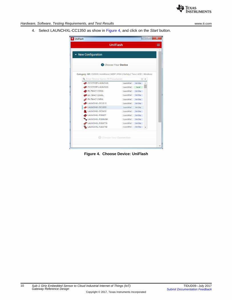
3.2.1.1.2 Program the MAC-CoP LaunchPad™1. It is assumed that all the required software is already installed on a Windows PC. If not, install the
required software now.2. Connect the MAC-CoP LaunchPad to the PC.3. Open UniFlash.
Hardware, Software, Testing Requirements, and Test Results www.ti.com
10 TIDUD09–July 2017Submit Documentation Feedback
Copyright © 2017, Texas Instruments Incorporated
Sub-1 GHz Embedded Sensor to Cloud Industrial Internet of Things (IoT)Gateway Reference Design
4. Select LAUNCHXL-CC1350 as show in Figure 4, and click on the Start button.
Figure 4. Choose Device: UniFlash

www.ti.com Hardware, Software, Testing Requirements, and Test Results
11TIDUD09–July 2017Submit Documentation Feedback
Copyright © 2017, Texas Instruments Incorporated
Sub-1 GHz Embedded Sensor to Cloud Industrial Internet of Things (IoT)Gateway Reference Design
5. Make sure the Program tab is selected on the right, and click the Browse button to select the desiredimage for the LaunchPad (CC1350 LaunchPad CoProcessor.hex or sensor_cc1350lp_doorlock.hex).
Figure 5. Browse for Firmware Image

Hardware, Software, Testing Requirements, and Test Results www.ti.com
12 TIDUD09–July 2017Submit Documentation Feedback
Copyright © 2017, Texas Instruments Incorporated
Sub-1 GHz Embedded Sensor to Cloud Industrial Internet of Things (IoT)Gateway Reference Design
6. After selecting the desired image, click on the Load Image button to flash the CC1350 LaunchPad.
Figure 6. Load Image
7. If loading the image was successful, a success message should show in the console as shown inFigure 7.
Figure 7. Successful Load
3.2.1.1.3 Program the Sensor LaunchPad™Follow the same steps in Section 3.2.1.1.2 to program the Sensor LaunchPad using the hex imagesensor_cc1350lp_doorlock.hex provided in the Sensor folder.
3.2.1.1.4 Programming the CC3220SF LaunchPad™This section describes two ways of programming the CC3220SF LaunchPad. Section 3.2.1.1.4.1 explainsthe process of programming the out-of-the-box demonstration by importing a preconfigured Image Creatorproject to UniFlash. Section 3.2.1.1.4.2 shows how to create an Image Creator project from scratch toprogram the CC3220SF with a binary generated from Code Composer Studio™.

www.ti.com Hardware, Software, Testing Requirements, and Test Results
13TIDUD09–July 2017Submit Documentation Feedback
Copyright © 2017, Texas Instruments Incorporated
Sub-1 GHz Embedded Sensor to Cloud Industrial Internet of Things (IoT)Gateway Reference Design
3.2.1.1.4.1 Programming the Preconfigured Image Creator Project1. Open UniFlash.2. On the Choose your Device section select CC3220SF-LAUNCHXL, and make sure to select the Serial
option and not On-Chip as shown in Figure 8. Click on the Start Image Creator button.
Figure 8. Choose Device: CC3220SF

Hardware, Software, Testing Requirements, and Test Results www.ti.com
14 TIDUD09–July 2017Submit Documentation Feedback
Copyright © 2017, Texas Instruments Incorporated
Sub-1 GHz Embedded Sensor to Cloud Industrial Internet of Things (IoT)Gateway Reference Design
3. After starting Image Creator, click on the Manage Projects button as shown in Figure 9.
Figure 9. Manage Project

www.ti.com Hardware, Software, Testing Requirements, and Test Results
15TIDUD09–July 2017Submit Documentation Feedback
Copyright © 2017, Texas Instruments Incorporated
Sub-1 GHz Embedded Sensor to Cloud Industrial Internet of Things (IoT)Gateway Reference Design
4. Click on the Import Project from ZIP file button, and select the zip folderC:\<S2C_Repo_Directory>\CC3220_CC13x0Gateway\prebuilt\CC3220SF_LaunchXL\Uniflash_CC3220ImageCreatorProject.zip.
Figure 10. Import Project

Hardware, Software, Testing Requirements, and Test Results www.ti.com
16 TIDUD09–July 2017Submit Documentation Feedback
Copyright © 2017, Texas Instruments Incorporated
Sub-1 GHz Embedded Sensor to Cloud Industrial Internet of Things (IoT)Gateway Reference Design
5. Open the CC3220SF_154StackGtway project.
Figure 11. Open Project

www.ti.com Hardware, Software, Testing Requirements, and Test Results
17TIDUD09–July 2017Submit Documentation Feedback
Copyright © 2017, Texas Instruments Incorporated
Sub-1 GHz Embedded Sensor to Cloud Industrial Internet of Things (IoT)Gateway Reference Design
6. Connect the device to the PC through a USB cable, and press the Connect button found on thebottom-right corner. Once the device is connected, select the Generate Image button underneath theDisconnect button, and select Program Image (Create & Program).
Figure 12. Generate Image

Hardware, Software, Testing Requirements, and Test Results www.ti.com
18 TIDUD09–July 2017Submit Documentation Feedback
Copyright © 2017, Texas Instruments Incorporated
Sub-1 GHz Embedded Sensor to Cloud Industrial Internet of Things (IoT)Gateway Reference Design
3.2.1.1.4.2 Creating an Image Creator ProjectThe following steps will allow the user to customize the example and use the new, updated files instead ofthe pre-build ones.1. Open UniFlash.2. On the Choose your Device section, select CC3220SF-LAUNCHXL. Make sure the Serial option is
selected and not On-Chip as shown in Figure 13. Click on the Start Image Creator button.
Figure 13. Select CC3220 Device

www.ti.com Hardware, Software, Testing Requirements, and Test Results
19TIDUD09–July 2017Submit Documentation Feedback
Copyright © 2017, Texas Instruments Incorporated
Sub-1 GHz Embedded Sensor to Cloud Industrial Internet of Things (IoT)Gateway Reference Design
3. After starting Image Creator, click on the New Project button as in Figure 14.
Figure 14. New Project
4. Enter a project name, select CC3220SF in the Device Type drop-down menu, make sure device modeis in Develop, and click on the Create Project button.
Figure 15. Starting a New Project

Hardware, Software, Testing Requirements, and Test Results www.ti.com
20 TIDUD09–July 2017Submit Documentation Feedback
Copyright © 2017, Texas Instruments Incorporated
Sub-1 GHz Embedded Sensor to Cloud Industrial Internet of Things (IoT)Gateway Reference Design
5. Select Trusted Root-Certificate Catalog in the bottom-left corner and uncheck the Use default TrustedRoot-Certificate Catalog box. Include the Source File (certcatalogPlayGround20160911.lst) andSignature Source File (certcatalogPlayGround20160911.lst.signed.bin) found inC:\ti\simplelink_cc32xx_sdk_1_30_01_03\tools\cc32xx_tools\certificate-catalog.
Figure 16. Trusted Root Certificates

www.ti.com Hardware, Software, Testing Requirements, and Test Results
21TIDUD09–July 2017Submit Documentation Feedback
Copyright © 2017, Texas Instruments Incorporated
Sub-1 GHz Embedded Sensor to Cloud Industrial Internet of Things (IoT)Gateway Reference Design
6. Select Service Pack in the bottom-left corner and include the service pack bin(sp_3.3.0.0_2.0.0.0_2.2.0.4.bin) found inC:\ti\simplelink_cc32xx_sdk_1_30_01_03\tools\cc32xx_tools\servicepack-cc3x20.
Figure 17. Service Pack

Hardware, Software, Testing Requirements, and Test Results www.ti.com
22 TIDUD09–July 2017Submit Documentation Feedback
Copyright © 2017, Texas Instruments Incorporated
Sub-1 GHz Embedded Sensor to Cloud Industrial Internet of Things (IoT)Gateway Reference Design
7. Select User Files and include the dummy-root-ca-cert and dummy-root-ca-cert-key files by clicking onthe Add File icon. These files can be found inC:\ti\simplelink_cc32xx_sdk_1_30_01_03\tools\cc32xx_tools\certificate-playground.Create a foldernamed www by clicking on the New Folder icon. This folder will contain all the web server requiredfiles.
NOTE: When adding the files do not select any of the options in the pop-up window—just click theWrite button.
Figure 18. User Files

www.ti.com Hardware, Software, Testing Requirements, and Test Results
23TIDUD09–July 2017Submit Documentation Feedback
Copyright © 2017, Texas Instruments Incorporated
Sub-1 GHz Embedded Sensor to Cloud Industrial Internet of Things (IoT)Gateway Reference Design
8. Include all the files and folders inside the C:\<S2C RepoDirectory>\CC3220_CC13x0Gateway\examples\CC3220SF_LaunchXLcc3220sf_gateway_app/15_4_Stack_Gtway_CC3220SF_LAUNCHXL_tirtos_ccs/www folder into the www folder of the device.
Figure 19. www Folder

Hardware, Software, Testing Requirements, and Test Results www.ti.com
24 TIDUD09–July 2017Submit Documentation Feedback
Copyright © 2017, Texas Instruments Incorporated
Sub-1 GHz Embedded Sensor to Cloud Industrial Internet of Things (IoT)Gateway Reference Design
9. On the drop-down box in the top-right corner, select Select MCU Image, and press Browse. On thenext menu select Private Key Name: and include the dummy-root-ca-cert-key. On the Certification FileName: select dummy-root-ca-cert from the list.
Figure 20. Select MCU Image

www.ti.com Hardware, Software, Testing Requirements, and Test Results
25TIDUD09–July 2017Submit Documentation Feedback
Copyright © 2017, Texas Instruments Incorporated
Sub-1 GHz Embedded Sensor to Cloud Industrial Internet of Things (IoT)Gateway Reference Design
10. Connect the device to the PC through a USB cable, and press the Connect button found on thebottom-right corner. Once the device is connected, select the Generate Image button underneath theDisconnect button. Select Program Image (Create & Program).
Figure 21. Generate Image

Hardware, Software, Testing Requirements, and Test Results www.ti.com
26 TIDUD09–July 2017Submit Documentation Feedback
Copyright © 2017, Texas Instruments Incorporated
Sub-1 GHz Embedded Sensor to Cloud Industrial Internet of Things (IoT)Gateway Reference Design
3.2.1.1.5 Connect the MAC-CoP LaunchPad™ With the CC3220SF LaunchPad™1. Remove all jumpers at the center of the MAC-Cop LaunchPad except the Reset jumper highlighted in
green . Also remove the VSENSE jumper highlighted in blue in Figure 22.
Figure 22. CC1350 LaunchPad™

www.ti.com Hardware, Software, Testing Requirements, and Test Results
27TIDUD09–July 2017Submit Documentation Feedback
Copyright © 2017, Texas Instruments Incorporated
Sub-1 GHz Embedded Sensor to Cloud Industrial Internet of Things (IoT)Gateway Reference Design
2. Stack both LaunchPad development kits on top of each other as shown in Figure 23.
Figure 23. Stacked CC1350 and CC3220SF LaunchPad™ Development Kits
3. Connect a USB cable only to the CC3220 LaunchPad, and plug it in the PC.4. Open a serial console (such as, PuTTy or Tera Term), select the COM port associated to the
CC3220SF LaunchPad, and open the port.

Hardware, Software, Testing Requirements, and Test Results www.ti.com
28 TIDUD09–July 2017Submit Documentation Feedback
Copyright © 2017, Texas Instruments Incorporated
Sub-1 GHz Embedded Sensor to Cloud Industrial Internet of Things (IoT)Gateway Reference Design
3.2.1.1.6 Open and Configure an IBM® Bluemix® Account1. It is assumed that all the required software is already installed on the Windows® PC. If not, install the
required software now.2. Go to Create IBM Bluemix Account, and register a 30 day trial account with an email address.3. Confirm the Bluemix account using the link provided by IBM through email.4. Log in to the Bluemix account, and walk through the steps on the screen.5. Once finished with the steps, click on the Catalog tab located on the top-right corner.
Figure 24. IBM ® Bluemix®

www.ti.com Hardware, Software, Testing Requirements, and Test Results
29TIDUD09–July 2017Submit Documentation Feedback
Copyright © 2017, Texas Instruments Incorporated
Sub-1 GHz Embedded Sensor to Cloud Industrial Internet of Things (IoT)Gateway Reference Design
6. After selecting the Catalog, click on Cloud Foundry Apps under Apps on the left menu.
Figure 25. IBM ® Bluemix ® Catalog
7. Choose SDK for Node.js from the options provided.
Figure 26. Create Node.js Application

Hardware, Software, Testing Requirements, and Test Results www.ti.com
30 TIDUD09–July 2017Submit Documentation Feedback
Copyright © 2017, Texas Instruments Incorporated
Sub-1 GHz Embedded Sensor to Cloud Industrial Internet of Things (IoT)Gateway Reference Design
8. Enter a name for the new Node.js application under the App name text box, and press the Createbutton on the bottom-right corner.
Figure 27. Name and Create Application
9. Once the app has been created, click on the Catalogtab located on the top-right corner.
Figure 28. Go to Catalog

www.ti.com Hardware, Software, Testing Requirements, and Test Results
31TIDUD09–July 2017Submit Documentation Feedback
Copyright © 2017, Texas Instruments Incorporated
Sub-1 GHz Embedded Sensor to Cloud Industrial Internet of Things (IoT)Gateway Reference Design
10. After selecting the Catalog, click on Internet of Things under Services on the left menu
Figure 29. IBM ® Bluemix ® Catalog
11. Choose Internet of Things Platform from the options provided.
Figure 30. IoT Service Options

Hardware, Software, Testing Requirements, and Test Results www.ti.com
32 TIDUD09–July 2017Submit Documentation Feedback
Copyright © 2017, Texas Instruments Incorporated
Sub-1 GHz Embedded Sensor to Cloud Industrial Internet of Things (IoT)Gateway Reference Design
12. Give the new platform a service name, and click on the Connect to drop-down menu. Select the cloudfoundry app name created in the previous steps. Click the Create button on the bottom-right corner.
Figure 31. Create IoT Platform
3.2.1.1.7 Set up Watson IoT™ Platform Service1. Click on the IBM Bluemix on the top-right corner, or use the drop-down menu and choose Dashboard
to open up the dashboard.
Figure 32. Go to Dashboard

www.ti.com Hardware, Software, Testing Requirements, and Test Results
33TIDUD09–July 2017Submit Documentation Feedback
Copyright © 2017, Texas Instruments Incorporated
Sub-1 GHz Embedded Sensor to Cloud Industrial Internet of Things (IoT)Gateway Reference Design
2. The cloud foundry apps and IoT services will be visible on the dashboard. Click on the IoT service.
Figure 33. Dashboard
3. On the Manage tab, click the Launch button.
Figure 34. Launch IoT Platform

Hardware, Software, Testing Requirements, and Test Results www.ti.com
34 TIDUD09–July 2017Submit Documentation Feedback
Copyright © 2017, Texas Instruments Incorporated
Sub-1 GHz Embedded Sensor to Cloud Industrial Internet of Things (IoT)Gateway Reference Design
4. Select Devices from the navigation bar on the left.
Figure 35. IoT Platform
5. Select Add Device on the top-right corner.
Figure 36. Add Device

www.ti.com Hardware, Software, Testing Requirements, and Test Results
35TIDUD09–July 2017Submit Documentation Feedback
Copyright © 2017, Texas Instruments Incorporated
Sub-1 GHz Embedded Sensor to Cloud Industrial Internet of Things (IoT)Gateway Reference Design
6. Select Create device type.
Figure 37. Create Device Type
7. Select Create gateway type.
Figure 38. Create Gateway Type
Hardware, Software, Testing Requirements, and Test Results www.ti.com
36 TIDUD09–July 2017Submit Documentation Feedback
Copyright © 2017, Texas Instruments Incorporated
Sub-1 GHz Embedded Sensor to Cloud Industrial Internet of Things (IoT)Gateway Reference Design
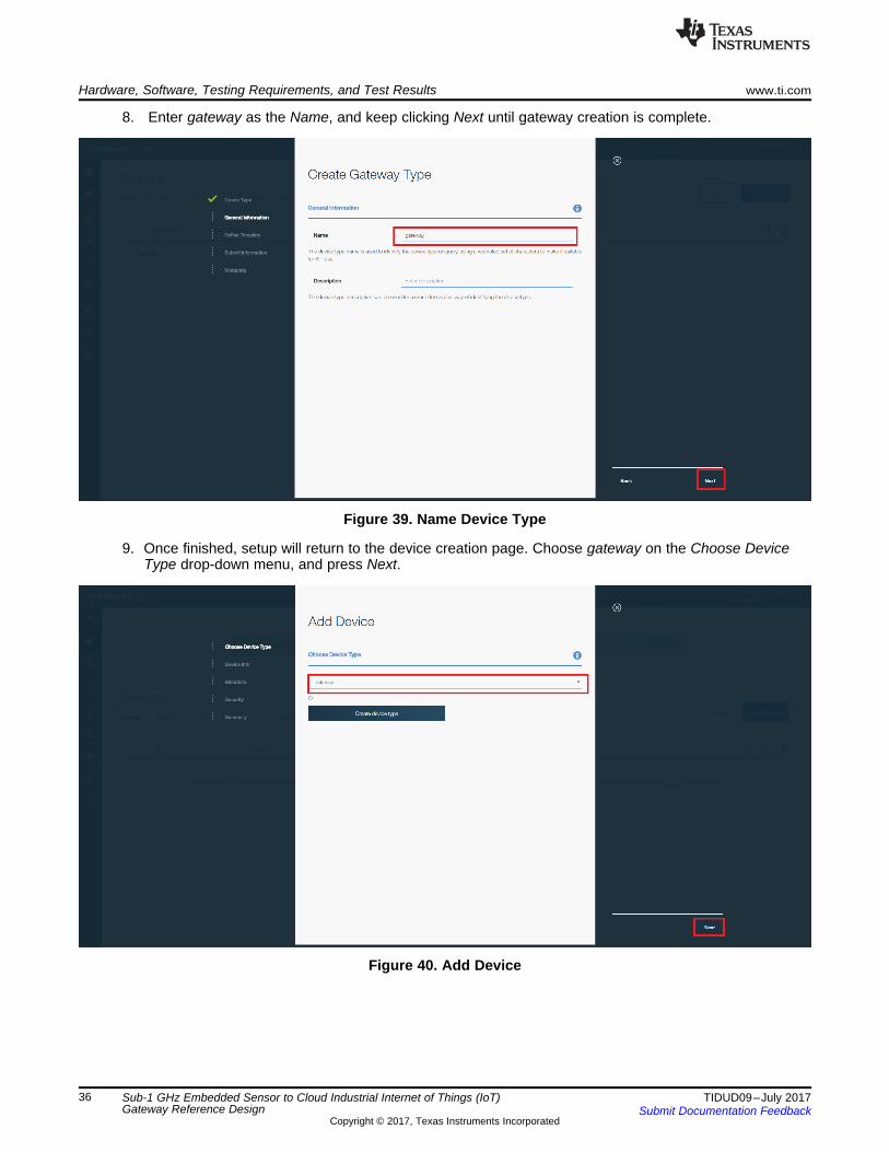
8. Enter gateway as the Name, and keep clicking Next until gateway creation is complete.
Figure 39. Name Device Type
9. Once finished, setup will return to the device creation page. Choose gateway on the Choose DeviceType drop-down menu, and press Next.
Figure 40. Add Device

www.ti.com Hardware, Software, Testing Requirements, and Test Results
37TIDUD09–July 2017Submit Documentation Feedback
Copyright © 2017, Texas Instruments Incorporated
Sub-1 GHz Embedded Sensor to Cloud Industrial Internet of Things (IoT)Gateway Reference Design
10. Enter a Device ID, and press Next. Ignore the metadata, and press Next again.
Figure 41. Device ID
11. On the Security tab, fill out the token field. Make note of this token, as this will be used forauthenticating the device to the cloud. Click Next.
Figure 42. Token

Hardware, Software, Testing Requirements, and Test Results www.ti.com
38 TIDUD09–July 2017Submit Documentation Feedback
Copyright © 2017, Texas Instruments Incorporated
Sub-1 GHz Embedded Sensor to Cloud Industrial Internet of Things (IoT)Gateway Reference Design
12. Keep clicking Next until a summary of the device credentials and information shows. Take ascreenshot of this page, as this will be the last time the Authentication Token is visible.
Figure 43. Save Authentication Credentials
3.2.1.1.8 Set up Node.js Cloud Foundry App1. Open UniFlash.2. Locate C:\<S2C Repo Directory>\CC3220_CC13x0Gateway\examples.3. Open the ibm_cloud_application folder, and open the Manifest.yml with a text editor. Replace the name
and services fields with the name of the cloud foundry app and Watson IoT platform.
Figure 44. Manifest

www.ti.com Hardware, Software, Testing Requirements, and Test Results
39TIDUD09–July 2017Submit Documentation Feedback
Copyright © 2017, Texas Instruments Incorporated
Sub-1 GHz Embedded Sensor to Cloud Industrial Internet of Things (IoT)Gateway Reference Design
4. Inside the same folder, open the package.json, and replace the name field with the name of the cloudfoundry app.
Figure 45. Package
5. Open a command console and navigate to the IBM-Cloud-Dashboard folder (cd C:\<S2C RepoDirectory>\CC3220_CC13x0Gateway\examples/ibm_cloud_application).
6. Type in cf api https://api.ng.bluemix.net.7. Log in to the created account: cf login.8. Push the code to the IBM cloud foundry app (cf push).

Hardware, Software, Testing Requirements, and Test Results www.ti.com
40 TIDUD09–July 2017Submit Documentation Feedback
Copyright © 2017, Texas Instruments Incorporated
Sub-1 GHz Embedded Sensor to Cloud Industrial Internet of Things (IoT)Gateway Reference Design
9. Go back to the IBM Bluemix Dashboard by clicking IBM Bluemix on the top left.
Figure 46. Dashboard
10. The cloud foundry apps and IoT services created on the previous on the dashboard will be visible.Click on the cloud foundry app.
Figure 47. Cloud Foundry App

www.ti.com Hardware, Software, Testing Requirements, and Test Results
41TIDUD09–July 2017Submit Documentation Feedback
Copyright © 2017, Texas Instruments Incorporated
Sub-1 GHz Embedded Sensor to Cloud Industrial Internet of Things (IoT)Gateway Reference Design
11. Click on the Connections tab to the left.
Figure 48. Connections
12. Click on the View credentials button. This page shows the information required to establish aconnection between the cloud front end and the back end server. Screenshot or save the informationfor later.
Figure 49. View Credentials

Hardware, Software, Testing Requirements, and Test Results www.ti.com
42 TIDUD09–July 2017Submit Documentation Feedback
Copyright © 2017, Texas Instruments Incorporated
Sub-1 GHz Embedded Sensor to Cloud Industrial Internet of Things (IoT)Gateway Reference Design
13. Now open the webpage, the link can be found on the dashboard next to the cloud foundry app name.
Figure 50. IBM® Web Page Link
14. If everything setup correctly, the dashboard will be visible. At this point, open the configuration menulocated on the top-left corner.
Figure 51. Sensor2Cloud Front End

www.ti.com Hardware, Software, Testing Requirements, and Test Results
43TIDUD09–July 2017Submit Documentation Feedback
Copyright © 2017, Texas Instruments Incorporated
Sub-1 GHz Embedded Sensor to Cloud Industrial Internet of Things (IoT)Gateway Reference Design
15. A form will pop up. Use the information saved in step 13 to fill out the form. For the Device Type andDevice ID, use the information saved in Section 3.2.1.1.3. Save the changes, and close when done.
Figure 52. IBM® IoT Credentials

Hardware, Software, Testing Requirements, and Test Results www.ti.com
44 TIDUD09–July 2017Submit Documentation Feedback
Copyright © 2017, Texas Instruments Incorporated
Sub-1 GHz Embedded Sensor to Cloud Industrial Internet of Things (IoT)Gateway Reference Design
3.2.1.1.9 Run and Use the GatewayThere are two ways to get the S2C Gateway up an running. The first method is described inSection 3.2.1.1.9.1, which explains how to provision the CC3220SF LaunchPad to a WiFi Network fromthe Simple Link Starter Pro App. The second method is explained in Section 3.2.1.1.9.2; this method usesthe built-in, local provisioning web page.
3.2.1.1.9.1 Using the SimpleLink™ Starter Pro AppThis section assumes that either the IOS or the Android app is already installed on the user's mobilephone. If not, install the app now.1. Launch the SimpleLink Starter Pro App from the phone.2. If the device is not found automatically by the app, go to Device to configure, and tap on search for
your device.
Figure 53. Configuration Page
3. Wait for the app to find the device to connect. The name should be something like mysimplelink-XXXX.

www.ti.com Hardware, Software, Testing Requirements, and Test Results
45TIDUD09–July 2017Submit Documentation Feedback
Copyright © 2017, Texas Instruments Incorporated
Sub-1 GHz Embedded Sensor to Cloud Industrial Internet of Things (IoT)Gateway Reference Design
4. Select the device to connect, and tap OK.
Figure 54. Select Device to Configure

Hardware, Software, Testing Requirements, and Test Results www.ti.com
46 TIDUD09–July 2017Submit Documentation Feedback
Copyright © 2017, Texas Instruments Incorporated
Sub-1 GHz Embedded Sensor to Cloud Industrial Internet of Things (IoT)Gateway Reference Design
5. Select the desired Wi-Fi network to connect with the CC3220SF LaunchPad. Enter the password, tapOK, and then tap Start Configuration.
Figure 55. Select Wi-Fi Router
6. After the configuration is done, make sure the phone is connected to the same Wi-Fi network that theCC3220SF is connected.

www.ti.com Hardware, Software, Testing Requirements, and Test Results
47TIDUD09–July 2017Submit Documentation Feedback
Copyright © 2017, Texas Instruments Incorporated
Sub-1 GHz Embedded Sensor to Cloud Industrial Internet of Things (IoT)Gateway Reference Design
7. Once connected, select the device from the device list.
Figure 56. Devices
8. This will open a web page hosted by the device with some information about the device network.
Hardware, Software, Testing Requirements, and Test Results www.ti.com
48 TIDUD09–July 2017Submit Documentation Feedback
Copyright © 2017, Texas Instruments Incorporated
Sub-1 GHz Embedded Sensor to Cloud Industrial Internet of Things (IoT)Gateway Reference Design
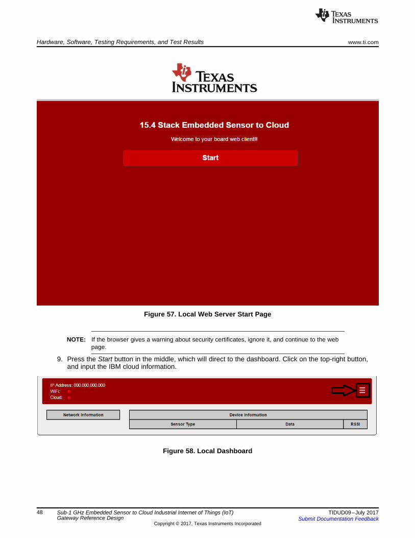
Figure 57. Local Web Server Start Page
NOTE: If the browser gives a warning about security certificates, ignore it, and continue to the webpage.
9. Press the Start button in the middle, which will direct to the dashboard. Click on the top-right button,and input the IBM cloud information.
Figure 58. Local Dashboard

www.ti.com Hardware, Software, Testing Requirements, and Test Results
49TIDUD09–July 2017Submit Documentation Feedback
Copyright © 2017, Texas Instruments Incorporated
Sub-1 GHz Embedded Sensor to Cloud Industrial Internet of Things (IoT)Gateway Reference Design
10. A form will pop up, and fill out the form with the IBM Bluemix account information. When complete,click Save Changes and then Close.
Figure 59. Cloud Credentials Form
11. Go to the URL provided on the IBM Bluemix account, which looks something likeAPP_NAME.mybluemix.net.
12. Click the open button on the dashboard to allow sensors to join the network.
Figure 60. Cloud Dashboard Open Button
13. Apply power to the LaunchPad labeled Sensor.14. Now the sensor should automatically start looking for a network. If paired with the network
successfully, the Sensor board can be viewed and controlled from the web browser.

Hardware, Software, Testing Requirements, and Test Results www.ti.com
50 TIDUD09–July 2017Submit Documentation Feedback
Copyright © 2017, Texas Instruments Incorporated
Sub-1 GHz Embedded Sensor to Cloud Industrial Internet of Things (IoT)Gateway Reference Design
NOTE: If the device is not visible in the web browser, the device is most likely connected to anothernetwork. To solve this error, complete a factory reset on the sensor by pressing the resetbutton while holding the right button (BTN-2), and try again.
Figure 61. Sensor2Cloud Front End
3.2.1.1.9.2 Using the Local Provisioning Web Page
NOTE: This is an alternate option if using the SimpleLink App is not desired.
1. Make sure the CC3220SF LaunchPad is powered on and that a serial console, like Tera Term, isopened to see the console output of the device.

www.ti.com Hardware, Software, Testing Requirements, and Test Results
51TIDUD09–July 2017Submit Documentation Feedback
Copyright © 2017, Texas Instruments Incorporated
Sub-1 GHz Embedded Sensor to Cloud Industrial Internet of Things (IoT)Gateway Reference Design
2. On the PC search for Wi-Fi networks, and connect to the one broadcasted by the LaunchPad, whichshould look something like mysimplelink-XXXX.
Figure 62. Connect to LaunchPad™

Hardware, Software, Testing Requirements, and Test Results www.ti.com
52 TIDUD09–July 2017Submit Documentation Feedback
Copyright © 2017, Texas Instruments Incorporated
Sub-1 GHz Embedded Sensor to Cloud Industrial Internet of Things (IoT)Gateway Reference Design
3. Open a browser window, and navigate to mysimplelink.net, as shown in Figure 63.
Figure 63. mysimplelink.net Local Home Page
4. Press the Start button in the middle to go to the Network Configuration page.
Figure 64. Network Configuration Page

www.ti.com Hardware, Software, Testing Requirements, and Test Results
53TIDUD09–July 2017Submit Documentation Feedback
Copyright © 2017, Texas Instruments Incorporated
Sub-1 GHz Embedded Sensor to Cloud Industrial Internet of Things (IoT)Gateway Reference Design
5. Enter the required information for the desired Wi-Fi access point, and click on the Add button. A pop-up window with instructions like Figure 65 will appear.
Figure 65. Pop-up Message
6. Go to Using SimpleLink Starter Pro App at the beginning of Section 3.2.1.1.9, and follow theinstructions starting from step 8.

Hardware, Software, Testing Requirements, and Test Results www.ti.com
54 TIDUD09–July 2017Submit Documentation Feedback
Copyright © 2017, Texas Instruments Incorporated
Sub-1 GHz Embedded Sensor to Cloud Industrial Internet of Things (IoT)Gateway Reference Design
3.2.2 Test Results
3.2.2.1 IoT DashboardFigure 66 is an example of the IoT dashboard displayed on the web interface. Note that the currentnetwork information is shown. The network chart displays the number of connected devices, and thesensor nodes section shows the device and current sensor information for all the devices in the network.
Figure 66. Sensor To Cloud Dashboard Results
3.2.2.2 TI IoT Gateway-to-Cloud Service InterfaceThe purpose of this section is to provide a description of the message types and expected data flows thatwill be shared between the TI IoT gateway and an IoT cloud server. The interface is designed to beflexible to support multiple cloud vendors. For this purpose, the Sub-1 GHz wireless network and nodeinformation will be exchanged between the gateway and the cloud using the long-established JavaScriptobject notation (JSON) format. Additionally, IPSO alliance smart object definitions will be used to definesensors (and their data) that are connected to each node in the wireless networks.
3.2.2.2.1 Message TypesTo fully specify the Sub-1 GHz wireless network information, as well as the Sub-1 GHz sensors and theirdata, two distinct message types have been defined for the IoT gateway to update the cloud. In order toallow the cloud to send messages back to the TI IoT gateway, two additional message types are definedthat allow the cloud to update the wireless network state and send actuation messages to specific devicesin the network.
3.2.2.2.1.1 Network Information Message Type (From TI IoT Gateway to the Cloud)This message type presents information about the wireless network, its current state, and a list of devicesthat are connected to the network. As described later in this design guide, this will be the first messagetype sent after the network is initialized.This message type contains all the information necessary toprepare for receiving sensor data from devices. This message type contains the following fields:• name: begins as the short address of the network but allows for the cloud to provide a more specific
name• channels: list of channels that the wireless network is operating on

www.ti.com Hardware, Software, Testing Requirements, and Test Results
55TIDUD09–July 2017Submit Documentation Feedback
Copyright © 2017, Texas Instruments Incorporated
Sub-1 GHz Embedded Sensor to Cloud Industrial Internet of Things (IoT)Gateway Reference Design
• pan_id: the 16-bit PAN identifier of the network• short_addr: the 16-bit short address of the PAN-coordinator• ext_addr: the 64-bit IEEE extended address of the PAN-coordinator device• security_enabled: yes, if security enabled; no, otherwise• mode: network operation mode (beacon, non-beacon, frequency hopping)• state: PAN-coordinator state values (waiting, starting, restoring, started, open, closed)• devices: list of wireless nodes in the network
– name: begins as the short address of the device but allows cloud to update– short_addr: the 16-bit short address of the PAN-coordinator– ext_addr: the 64-bit IEEE extended address of the PAN-coordinator device– topic: the topic that the device will send its sensor data updates to– object_list: list of IPSO alliance smart objects (sensors) attached to this device
• oid: object ID which specifies the sensor type in the IPSO standard• iid: list of instance IDs for the current object (can be multiple same type sensors)
3.2.2.2.1.2 Device Information Message Type (From TI IoT Gateway to the Cloud)This message type provides information about the wireless device as well as the latest data for all of thesensors connected to the device. This message type will be sent when a device reports sensor data orswitches between an active or inactive state. The following fields are contained in this message type:• active: whether or not the wireless node is active• ext_addr: the 64-bit IEEE extended address of the PAN-coordinator device• rssi: received signal strength indicator of the last message received• smart_objects: list of the IPSO alliance smart objects connected to this wireless device
– object ID description: type of sensor (as defined in the IPSO standard); can be multiple types ofsensors connected to each device
– instance ID: the instance ID for the parent object type; can be multiple sensors of the same type– resource ID description list: sensor data name value pairs (for example, sensorValue: 32.5, units:
Celsius, and so forth); these resources match what is specified for the given object ID in the IPSOstandard
3.2.2.2.1.3 Update Network State Message Type (From Cloud to TI IoT Gateway)In the current implementation of the TI IoT gateway, this message type is intended to be able to open orclose the wireless network to new devices joining. The cloud’s front end user interface can allow a user toclick a button to open or close the network and then generate this message type and send it to the TI IoTgateway. The gateway will then notify the network on whether it needs to open or close to new devicejoins. This message type only includes the desired state of the network and should be sent to the sametopic that the cloud is receiving the network information messages from. The following field is all that isrequired:• state: should be set to either open or closed
3.2.2.2.1.4 Device Actuation Message Type (From Cloud to TI IoT Gateway)This message type is added to allow the cloud to send actuation messages to specific devices in thewireless network. The current implementation only supports toggling an LED on the wireless device’sboard. The device actuation message should be sent to the topic of the device as given in the devices listof the network information message. The following field is the only requirement for this message:• toggleLED: should be set to true

Hardware, Software, Testing Requirements, and Test Results www.ti.com
56 TIDUD09–July 2017Submit Documentation Feedback
Copyright © 2017, Texas Instruments Incorporated
Sub-1 GHz Embedded Sensor to Cloud Industrial Internet of Things (IoT)Gateway Reference Design
3.2.2.2.2 Data Flows
3.2.2.2.2.1 Network Information Sent to the CloudThe following bulleted items are the list of events that can occur on the TI IoT gateway that will cause anetwork information message type to be sent to the cloud. A description is given with each event and theend of this section describes the expected behavior from the cloud upon receipt of this type of message.• Network Startup
This is the initial event in the TI IoT gateway. The TI IoT gateway will aggregate the information aboutthe wireless network as well as the list of connected devices and their sensor types. The TI IoTgateway will then make a connection to the cloud and send the aggregated data contained in thenetwork information message type.
• Network Information UpdateThis event can occur if any of the information about the wireless network changes. For example, if thenetwork operation mode of the wireless network was changed, the TI IoT gateway would once againaggregate all the information needed (network information and device list) and send the networkinformation message type to the cloud.
• Network State ChangeThis event occurs if the state of the wireless network changes. For example, if the network statechanges from open to closed the TI IoT gateway will send a network information message type to thecloud.
• Device Joins the Wireless NetworkWhen a new device joins the network, after the network is up and running, this event will occur. In thiscase, the TI IoT gateway will add the new device and its information to the devices list within thenetwork information message type and then send the updated information to the cloud.
• Expected Cloud BehaviorIt is expected that the cloud will be prepared for the network startup event and will be able to receivethe network information message type (using a wildcard and then filtering or by having prior knowledgeabout the destination or topic of the message). Once the cloud receives the network informationmessage, the wireless network information (PANID, security, mode, and so on) can be displayed tousers and the device list information (topic, object list, and so on) can be used to prepare itself toreceive and display device and sensor data.
3.2.2.2.2.2 Device Information Sent to the CloudThe following bulleted items are the list of events that will cause the TI IoT gateway to send a deviceinformation message type to the cloud. A description is given with each event and the end of this sectiondescribes the expected behavior from the cloud upon receipt of this type of message.• Device Becomes Inactive
This event occurs when the TI IoT gateway detects that one of the devices in the connected deviceslist has stopped sending sensor data updates. The TI IoT gateway will update the active field and senda Device Information Message Type to the cloud for the inactive device.
• Device Reports Sensor DataEach time a sensor on a connected device reports sensor data this event occurs. The TI IoT gatewayupdates the IPSO Alliance Smart Object list in the device for each sensor and then sends a deviceinformation message type to the cloud.
• Expected Cloud BehaviorIt is expected that the cloud will be listening on each topic given in the connected devices list from thenetwork information message. When one of the two events occur in this section, the TI IoT gatewaywill send the device information message to the topic (corresponding to the device being update) thatthe cloud should be listening on or subscribed to. When the device information message arrives at thecloud, the cloud should display the latest device information and sensor data to users.

www.ti.com Hardware, Software, Testing Requirements, and Test Results
57TIDUD09–July 2017Submit Documentation Feedback
Copyright © 2017, Texas Instruments Incorporated
Sub-1 GHz Embedded Sensor to Cloud Industrial Internet of Things (IoT)Gateway Reference Design
3.2.2.2.2.3 Update Network State Message Sent to the TI IoT GatewayThis message is used to open or close the wireless network to new devices joining. This message shouldbe an option provided to users in the front end user interface that the cloud presents. When the userdecides to update the network state, the cloud should send an update network state message type to theTI IoT gateway on the same topic that the network information messages are arriving on.• Expected TI IoT Gateway Behavior
The TI IoT gateway will receive the Update Network State message and will generate the correctcommand (either open or close) to the wireless network. This message should in turn cause a networkstate change event (from 7.2.1 above) that will send a network information message back to the cloudwhich can confirm the successful completion of the Update Network State command.
3.2.2.2.2.4 Device Actuation Message Sent to the TI IoT GatewayThis method is used to toggle the LED on the board of the connected devices. This message is meant tobe a proof-of-concept on the current device setup and will change for customer use-case specificactuations. A toggle LED button for each device will be provided to users of the cloud’s front end interface.When the toggle LED button is clicked the cloud should send a device actuation message to the TI IoTgateway on the same topic that the device information messages are arriving on.• Expected TI IoT Gateway Behavior
The TI IoT gateway will generate a toggle LED command and send it to the device corresponding tothe topic that the device actuation message was received on. This will cause the LED to toggle.Because the state of the LED is not captured in the device information message type, there will be nofeedback to the cloud that the LED actually toggled.

Design Files www.ti.com
58 TIDUD09–July 2017Submit Documentation Feedback
Copyright © 2017, Texas Instruments Incorporated
Sub-1 GHz Embedded Sensor to Cloud Industrial Internet of Things (IoT)Gateway Reference Design
4 Design FilesThis TI Design showcases the connectivity between CC3220SF and CC13x0 devices. The CC3220SFacts as a gateway processor and the CC13x0 as communication node. The CC3220SF LaunchPad isused as a platform for gateway processor, and the CC13x0-based LaunchPad acts as communicationnode. The recommended schematics for this TI Design uses the schematics of the CC3220SF LaunchPadand CC13x0 LaunchPad and interface the two devices using the UART lines. This IoT gateway referencedesign only uses one UART port. In addition, bootloader backdoor pins are described in theCC2538/CC26xx Serial Bootloader Interface application report. These pins can be connected to upgradethe firmware on the CC13x0 using the serial ROM bootloader on the CC13x0 devices.
4.1 SchematicTo download the schematics for this reference design, see the following links:• LAUNCHXL-CC1310• LAUNCHXL-CC1350• CC3220SF-LAUNCHXL
4.2 Bill of Materials• LAUNCHXL-CC1310• LAUNCHXL-CC1350• CC3220SF-LAUNCHXL
4.3 PCB Layout RecommendationsFor layout prints, Altium project files, Gerber files, and assembly drawings, see the following links:• LAUNCHXL-CC1310• LAUNCHXL-CC1350• CC3220SF-LAUNCHXL
5 Software FilesTo download the software files for this reference design, see the link athttps://git.ti.com/tidc01002/tidc01002.
6 Related Documentation1. Texas Instruments, SimpleLink TI 15.4-Stack IEEE 802.15.4e/g Standard Based Star Networking
Software Development Kit, Tools Folder2. Texas Instruments, SimpleLink CC3220 SDK, Tools Folder3. Texas Instruments, TI 15.4-Stack Wiki, Wiki Page4. Texas Instruments, TI 15.4-Stack Embedded Developers Guide
6.1 TrademarksSimpleLink, LaunchPad, Internet-on-a-chip, SmartConfig, Code Composer Studio are trademarks of TexasInstruments Incorporated.Cortex is a registered trademark of ARM Limited.ARM is a registered trademark of ARM Ltd.Bluetooth is a registered trademark of Bluetooth SIG, Incorporated.IOS is a registered trademark of Cisco.Android is a trademark of Google Inc..Watson IoT is a trademark of International Business Machines Corporation.IBM Watson IoT, Bluemix are registered trademarks of International Business Machines Corporation.Linux is a registered trademark of Linux Foundation.Windows is a registered trademark of Microsoft Corporation.Wi-Fi, Wi-Fi Direct are registered trademarks of Wi-Fi Alliance.

www.ti.com About the Authors
59TIDUD09–July 2017Submit Documentation Feedback
Copyright © 2017, Texas Instruments Incorporated
Sub-1 GHz Embedded Sensor to Cloud Industrial Internet of Things (IoT)Gateway Reference Design
7 About the AuthorsHECTOR RAMOS is a software applications engineer at Texas Instruments, where he has been workingat since 2014 and is specialized in low-power wireless protocols. Hector earned his bachelors of sciencein electrical engineering and computer science from University of California Berkeley.
ANDRES BLANCO is an applications engineer at Texas Instruments, where he is responsible forsupporting customers designing low power wireless systems. Andres earned his bachelor of science incomputer engineering from University of Puerto Rico in Mayagüez, PR.

IMPORTANT NOTICE FOR TI DESIGN INFORMATION AND RESOURCES
Texas Instruments Incorporated (‘TI”) technical, application or other design advice, services or information, including, but not limited to,reference designs and materials relating to evaluation modules, (collectively, “TI Resources”) are intended to assist designers who aredeveloping applications that incorporate TI products; by downloading, accessing or using any particular TI Resource in any way, you(individually or, if you are acting on behalf of a company, your company) agree to use it solely for this purpose and subject to the terms ofthis Notice.TI’s provision of TI Resources does not expand or otherwise alter TI’s applicable published warranties or warranty disclaimers for TIproducts, and no additional obligations or liabilities arise from TI providing such TI Resources. TI reserves the right to make corrections,enhancements, improvements and other changes to its TI Resources.You understand and agree that you remain responsible for using your independent analysis, evaluation and judgment in designing yourapplications and that you have full and exclusive responsibility to assure the safety of your applications and compliance of your applications(and of all TI products used in or for your applications) with all applicable regulations, laws and other applicable requirements. Yourepresent that, with respect to your applications, you have all the necessary expertise to create and implement safeguards that (1)anticipate dangerous consequences of failures, (2) monitor failures and their consequences, and (3) lessen the likelihood of failures thatmight cause harm and take appropriate actions. You agree that prior to using or distributing any applications that include TI products, youwill thoroughly test such applications and the functionality of such TI products as used in such applications. TI has not conducted anytesting other than that specifically described in the published documentation for a particular TI Resource.You are authorized to use, copy and modify any individual TI Resource only in connection with the development of applications that includethe TI product(s) identified in such TI Resource. NO OTHER LICENSE, EXPRESS OR IMPLIED, BY ESTOPPEL OR OTHERWISE TOANY OTHER TI INTELLECTUAL PROPERTY RIGHT, AND NO LICENSE TO ANY TECHNOLOGY OR INTELLECTUAL PROPERTYRIGHT OF TI OR ANY THIRD PARTY IS GRANTED HEREIN, including but not limited to any patent right, copyright, mask work right, orother intellectual property right relating to any combination, machine, or process in which TI products or services are used. Informationregarding or referencing third-party products or services does not constitute a license to use such products or services, or a warranty orendorsement thereof. Use of TI Resources may require a license from a third party under the patents or other intellectual property of thethird party, or a license from TI under the patents or other intellectual property of TI.TI RESOURCES ARE PROVIDED “AS IS” AND WITH ALL FAULTS. TI DISCLAIMS ALL OTHER WARRANTIES ORREPRESENTATIONS, EXPRESS OR IMPLIED, REGARDING TI RESOURCES OR USE THEREOF, INCLUDING BUT NOT LIMITED TOACCURACY OR COMPLETENESS, TITLE, ANY EPIDEMIC FAILURE WARRANTY AND ANY IMPLIED WARRANTIES OFMERCHANTABILITY, FITNESS FOR A PARTICULAR PURPOSE, AND NON-INFRINGEMENT OF ANY THIRD PARTY INTELLECTUALPROPERTY RIGHTS.TI SHALL NOT BE LIABLE FOR AND SHALL NOT DEFEND OR INDEMNIFY YOU AGAINST ANY CLAIM, INCLUDING BUT NOTLIMITED TO ANY INFRINGEMENT CLAIM THAT RELATES TO OR IS BASED ON ANY COMBINATION OF PRODUCTS EVEN IFDESCRIBED IN TI RESOURCES OR OTHERWISE. IN NO EVENT SHALL TI BE LIABLE FOR ANY ACTUAL, DIRECT, SPECIAL,COLLATERAL, INDIRECT, PUNITIVE, INCIDENTAL, CONSEQUENTIAL OR EXEMPLARY DAMAGES IN CONNECTION WITH ORARISING OUT OF TI RESOURCES OR USE THEREOF, AND REGARDLESS OF WHETHER TI HAS BEEN ADVISED OF THEPOSSIBILITY OF SUCH DAMAGES.You agree to fully indemnify TI and its representatives against any damages, costs, losses, and/or liabilities arising out of your non-compliance with the terms and provisions of this Notice.This Notice applies to TI Resources. Additional terms apply to the use and purchase of certain types of materials, TI products and services.These include; without limitation, TI’s standard terms for semiconductor products http://www.ti.com/sc/docs/stdterms.htm), evaluationmodules, and samples (http://www.ti.com/sc/docs/sampterms.htm).
Mailing Address: Texas Instruments, Post Office Box 655303, Dallas, Texas 75265Copyright © 2017, Texas Instruments Incorporated