sub title : analog electronic circuits cie+ assignment+ … · 2019-07-30 · jfet, transfer...
TRANSCRIPT
UNIT
No
Syllabus Content
No of
Hours
1
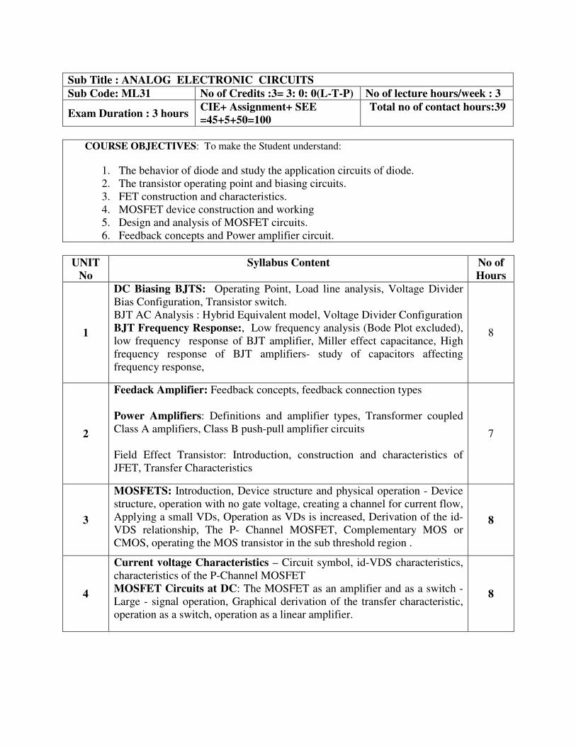
DC Biasing BJTS: Operating Point, Load line analysis, Voltage Divider
Bias Configuration, Transistor switch.
BJT AC Analysis : Hybrid Equivalent model, Voltage Divider Configuration
BJT Frequency Response:, Low frequency analysis (Bode Plot excluded),
low frequency response of BJT amplifier, Miller effect capacitance, High
frequency response of BJT amplifiers- study of capacitors affecting
frequency response,
8
2
Feedack Amplifier: Feedback concepts, feedback connection types
Power Amplifiers: Definitions and amplifier types, Transformer coupled
Class A amplifiers, Class B push-pull amplifier circuits
Field Effect Transistor: Introduction, construction and characteristics of
JFET, Transfer Characteristics
7
3
MOSFETS: Introduction, Device structure and physical operation - Device
structure, operation with no gate voltage, creating a channel for current flow,
Applying a small VDs, Operation as VDs is increased, Derivation of the id-
VDS relationship, The P- Channel MOSFET, Complementary MOS or
CMOS, operating the MOS transistor in the sub threshold region .
8
4
Current voltage Characteristics – Circuit symbol, id-VDS characteristics,
characteristics of the P-Channel MOSFET
MOSFET Circuits at DC: The MOSFET as an amplifier and as a switch -
Large - signal operation, Graphical derivation of the transfer characteristic,
operation as a switch, operation as a linear amplifier.
8
Sub Title : ANALOG ELECTRONIC CIRCUITS
Sub Code: ML31 No of Credits :3= 3: 0: 0(L-T-P) No of lecture hours/week : 3
Exam Duration : 3 hours CIE+ Assignment+ SEE
=45+5+50=100
Total no of contact hours:39
COURSE OBJECTIVES: To make the Student understand:
1. The behavior of diode and study the application circuits of diode.
2. The transistor operating point and biasing circuits.
3. FET construction and characteristics.
4. MOSFET device construction and working
5. Design and analysis of MOSFET circuits.
6. Feedback concepts and Power amplifier circuit.

5
Biasing in MOS amplifier circuits - Biasing by fixing VGS, Biasing by
fixing VG and connecting a resistor in the source , Biasing using a drain to
gate feedback resistor, biasing using a current source.
Small - signal operation and models of MOSFETs - The DC bias point,
the signal current in the drain terminal ,the voltage gain, separating dc
analysis and the signal analysis, small signal equivalent circuit models, the
transconductance gm, the T equivalent circuit model.
8
Note 1: Assignment-1 from unit 1 and 2.
Asssignment-2 from unit 3, 4 and 5
TEXT BOOK:
1. Electronic Devices and Circuit Theory, Robert L. Boylestad and Louis Nashelsky,
PHI/Pearson Education, 9th
Edition.
2. Microelectronic Circuits Theory and Applications, Adel S Sedra and Kenneth C Smith
Oxford International Student edition, 6th
edition
Text Book 1: Unit 1, Unit 2, Unit 5
Text Book 1: Unit 3, Unit 4,
REFERENCE BOOKS:
1. Integrated Electronics, Jacob Milman & Christos C. Halkias, Tata - McGraw Hill, 1991
Edition.
2. Electronic Devices and Circuits, David A. Bell, PHI, 4th
Edition, 2004.
CHAIRMAN/BOS DEAN (ACADEMIC) CHAIRMAN/ACADEMIC COUNCIL
COURSE OUTCOMES: On completion of the course the student will be able to
CO1: Design biasing circuits for BJTs and MOSFETS
CO2: Classify feedback amplifiers and power amplifiers
CO3: Determine the cut off frequencies for practical transistor amplifiers
CO4: Illustrate the procedure & working of construction of FET, MOSFET
CO5: Draw equivalent circuit models for BJTs and MOSFET
CO6: Differentiate the amplifier and switch functionality of BJTs and MOSFETs
COs Mapping with POs
CO1 PO1,PO2,PO3,PO4
CO2 PO1,PO2,PO3,PO4
CO3 PO1,PO2,PO3,PO4
CO4 PO1,PO2,PO3,PO4,PO7

UNIT
No
Syllabus Content No of
Hours
Tuto
rials
1
Principles of combinational logic-1: Definition of combinational logic, Canonical
forms, Generation of switching equations from truth tables, Karnaugh maps-3, 4
and 5 variables, Incompletely specified functions (Don’t Care terms), Simplifying
Max term equations.
Principles of combinational Logic-2: Quine-McCluskey minimization technique-
Quine-McCluskey using don’t care terms, Reduced Prime Implicant Tables.
Introduction to VHDL: Structure of VHDL Module, Operators, Data types,
Types of Descriptions, simulation and synthesis. Data flow description, behavioral
description and structural description.
8 4
2
Analysis and design of combinational logic - I: General approach, Decoders-
BCD decoders, Encoders.
Analysis and design of combinational logic - II: Digital multiplexers- Using
multiplexers as Boolean function generators. Adders and subtractors-Cascading full
adders, Binary comparators.
VHDL Implementation: Decoder, Encoder, Comparator, Adder/Subtractor
8 4
3
Sequential Circuits – 1: Basic Bistable Element, Latches, SR Latch, Application
of SR Latch, A Switch Debouncer, The RS Latch, The gated SR Latch, The gated
D Latch, Master-Slave SR Flip-Flops, The Master-Slave JK Flip-Flop,T Flip
Flop,D Flip flop.
VHDL Implementation – Sequential Circuits: Flip Flops
8 4
4
Sequential Circuits – 2: Characteristic Equations, Registers, Counters - Binary
Ripple Counters, Asynchronous counters, Synchronous Binary counters, Counters
based on Shift Registers, Design of a Synchronous counters using JK Flip-Flop, D
Flip-Flop, T Flip-Flop.
8 -
5
Sequential Design - I: Introduction, Mealy and Moore Models, State Machine
Notation, Synchronous Sequential Circuit Analysis.
Sequential Design – II: Construction of state diagrams, counter design. 8 -
Note 1: Assignment-1 Comparative study of different logic families
Asssignment-2 from unit 3, 4 and 5
Sub Title : LOGIC DESIGN and VHDL
Sub Code: ML32 No of Credits : 3=3:2:0(L-T-P) No of lecture hours/week : 3
Exam Duration : 3 hours CIE+ Assignment+ SEE
=45+5+50=100
Total no of contact hours:52
COURSE OBJECTIVES: To make the Student understand
1. Principles of combinational and sequential logic.
2. Different Boolean expression reduction techniques.
3. The design and analysis of combinational circuits.
4. The integrated circuit technologies.
5. Different flip flops and its applications. 6. Sequential circuit models
TEXT BOOKS:
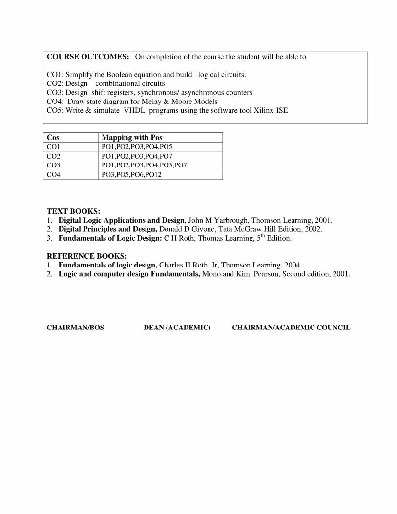
1. Digital Logic Applications and Design, John M Yarbrough, Thomson Learning, 2001.
2. Digital Principles and Design, Donald D Givone, Tata McGraw Hill Edition, 2002.
3. Fundamentals of Logic Design: C H Roth, Thomas Learning, 5th
Edition.
REFERENCE BOOKS:
1. Fundamentals of logic design, Charles H Roth, Jr, Thomson Learning, 2004.
2. Logic and computer design Fundamentals, Mono and Kim, Pearson, Second edition, 2001.
CHAIRMAN/BOS DEAN (ACADEMIC) CHAIRMAN/ACADEMIC COUNCIL
COURSE OUTCOMES: On completion of the course the student will be able to
CO1: Simplify the Boolean equation and build logical circuits.
CO2: Design combinational circuits
CO3: Design shift registers, synchronous/ asynchronous counters
CO4: Draw state diagram for Melay & Moore Models
CO5: Write & simulate VHDL programs using the software tool Xilinx-ISE
Cos Mapping with Pos
CO1 PO1,PO2,PO3,PO4,PO5
CO2 PO1,PO2,PO3,PO4,PO7
CO3 PO1,PO2,PO3,PO4,PO5,PO7
CO4 PO3,PO5,PO6,PO12
UNIT
No Syllabus Content
No of
Hours
1
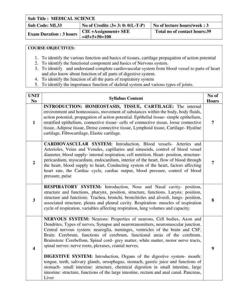
INTRODUCTION: HOMEOSTASIS, TISSUE, CARTILAGE: The internal
environment and homeostasis, movement of substances within the body, body fluids,
action potential, propagation of action potential. Epithelial tissue- simple epithelium,
stratified epithelium, connective tissue- cells of connective tissue, loose connective
tissue, Adipose tissue, Dense connective tissue, Lymphoid tissue, Cartilage- Hyaline
cartilage, Fibrocartilage, Elastic cartilage.
7
2
CARDIOVASCULAR SYSTEM: Introduction, Blood vessels- Arteries and
Arterioles, Veins and Venules, capillaries and sinusoids, control of blood vessel
diameter, blood supply- internal respiration, cell nutrition. Heart- position, structure-
pericardium, myocardium, endocardium, interior of the heart, flow of blood through
the heart, blood supply to heart, Conducting system of the heart, factors affecting
heart rate, the Cardiac cycle, cardiac output, blood pressure, control of blood
pressure, pulse
7
3
RESPIRATORY SYSTEM: Introduction, Nose and Nasal cavity- position,
structure and functions, pharynx, position, structure, functions. Larynx: position,
structure and functions. Trachea, bronchi, bronchioles and alveoli, lungs- position,
associated structure, pleura and pleural cavity. Respiration- muscles of respiration
cycle of respiration, variables affecting respiration, lung volumes and capacity.
8
4
NERVOUS SYSTEM: Neurons: Properties of neurons, Cell bodies, Axon and
Dendrites, Types of nerves, Synapse and neurotransmitters, neuromuscular junction.
Central nervous system: neuroglia, meninges, ventricles of the brain and CSF.
Brain: Cerebrum, functions of cerebrum, functional areas of the cerebrum.
Brainstem: Cerebellum, Spinal cord- grey matter, white matter, motor nerve tracts,
spinal nerves: nerve roots, plexuses, cranial nerves.
DIGESTIVE SYSTEM: Introduction, Organs of the digestive system- mouth:
tongue, teeth, salivary glands, oesophagus, stomach, gastric juice and functions of
stomach- small intestine: structure, chemical digestion in small intestine, large
intestine: structure, functions of the large intestine, rectum and anal canal. Pancreas,
Liver
9
Sub Title : MEDICAL SCIENCE
Sub Code: ML33 No of Credits :3= 3: 0: 0(L-T-P) No of lecture hours/week : 3
Exam Duration : 3 hours CIE +Assignment+ SEE
=45+5+50=100
Total no of contact hours:39
COURSE OBJECTIVES:
1. To identify the various function and basics of tissues, cartilage propagation of action potential
2. To identify the functional component and basics of Nervous system.
3. To identify and understand complete cardiovascular system from blood vessel to parts of heart
and also know about function of all parts of digestive system.
4. To identify the function of all the parts of respiratory system
5. To identify the importance function of skeletal system and various types of joints.
5
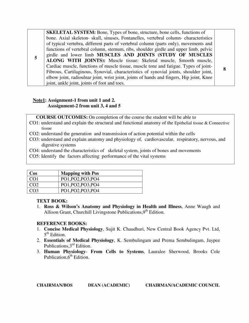
SKELETAL SYSTEM: Bone, Types of bone, structure, bone cells, functions of
bone. Axial skeleton- skull, sinuses, Fontanelles, vertebral column- characteristics
of typical vertebra, different parts of vertebral column (parts only), movements and
functions of vertebral column, sternum, ribs, shoulder girdle and upper limb, pelvic
girdle and lower limb MUSCLES AND JOINTS (STUDY OF MUSCLES
ALONG WITH JOINTS): Muscle tissue: Skeletal muscle, Smooth muscle,
Cardiac muscle, functions of muscle tissue, muscle tone and fatigue. Types of joint-
Fibrous, Cartilaginous, Synovial, characteristics of synovial joints, shoulder joint,
elbow joint, radioulnar joint, wrist joint, joints of hands and fingers, Hip joint, Knee
joint, ankle joint, joints of foot and toes.
8
Note1: Assignment-1 from unit 1 and 2.
Asssignment-2 from unit 3, 4 and 5
COURSE OUTCOMES: On completion of the course the student will be able to
CO1: understand and explain the structural and functional anatomy of the Epithelial tissue & Connective
tissue
CO2: understand the generation and transmission of action potential within the cells
CO3: understand and explain anatomy and physiology of, cardiovascular, respiratory, nervous, and
digestive systems
CO4: understand the characteristics of skeletal system, joints of bones and movements
CO5: Identify the factors affecting performance of the vital systems
TEXT BOOK:
1. Ross & Wilson’s Anatomy and Physiology in Health and Illness, Anne Waugh and
Allison Grant, Churchill Livingstone Publications,9th
Edition.
REFERENCE BOOKS:
1. Concise Medical Physiology, Sujit K. Chaudhuri, New Central Book Agency Pvt. Ltd,
5th
Edition.
2. Essentials of Medical Physiology, K. Sembulingam and Prema Sembulingam, Jaypee
Publications,3rd
Edition.
3. Human Physiology- From Cells to Systems, Lauralee Sherwood, Brooks Cole
Publication,6th
Edition.
CHAIRMAN/BOS DEAN (ACADEMIC) CHAIRMAN/ACADEMIC COUNCIL
Cos Mapping with Pos
CO1 PO1,PO2,PO3,PO4
CO2 PO1,PO2,PO3,PO4
CO3 PO1,PO2,PO3,PO4
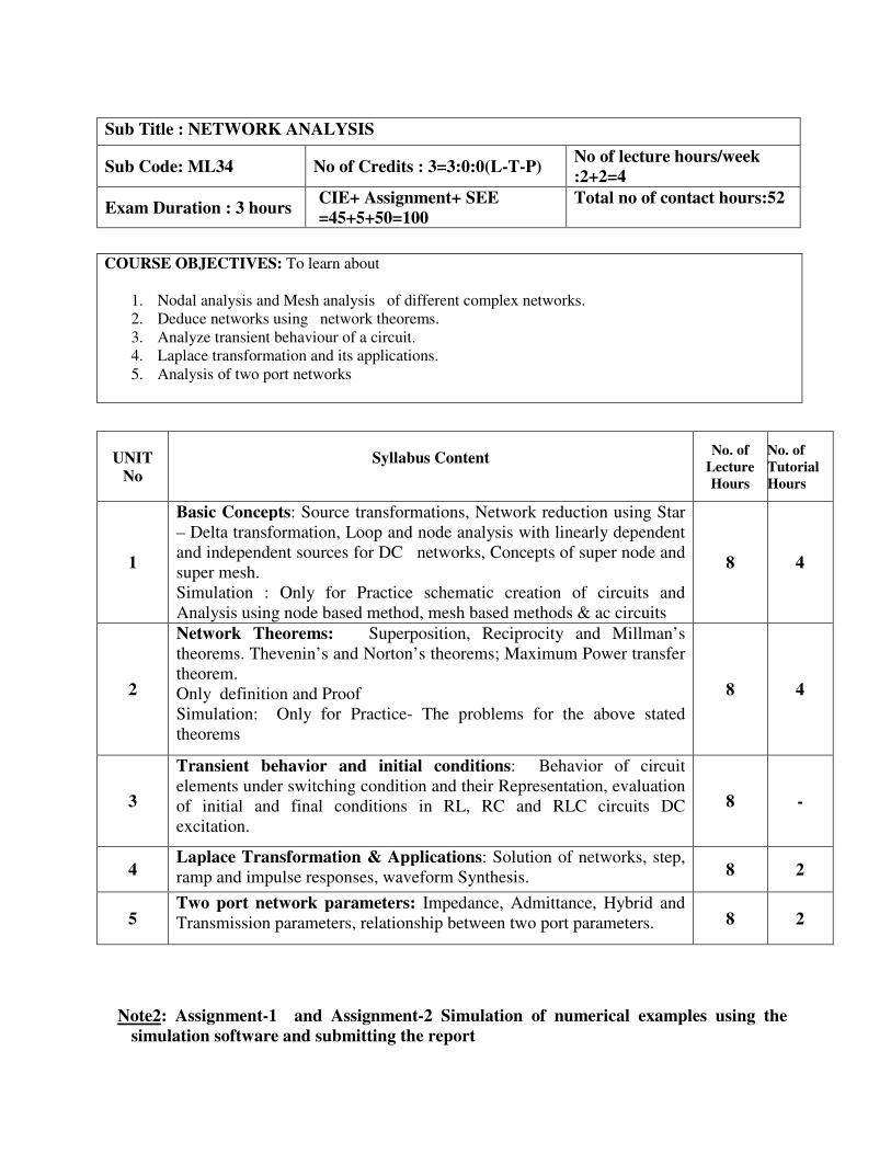
Note2: Assignment-1 and Assignment-2 Simulation of numerical examples using the
simulation software and submitting the report
Sub Title : NETWORK ANALYSIS
Sub Code: ML34 No of Credits : 3=3:0:0(L-T-P)
No of lecture hours/week
:2+2=4
Exam Duration : 3 hours CIE+ Assignment+ SEE
=45+5+50=100
Total no of contact hours:52
COURSE OBJECTIVES: To learn about
1. Nodal analysis and Mesh analysis of different complex networks.
2. Deduce networks using network theorems.
3. Analyze transient behaviour of a circuit.
4. Laplace transformation and its applications.
5. Analysis of two port networks
UNIT
No
Syllabus Content
No. of
Lecture
Hours
No. of
Tutorial
Hours
1
Basic Concepts: Source transformations, Network reduction using Star
– Delta transformation, Loop and node analysis with linearly dependent
and independent sources for DC networks, Concepts of super node and
super mesh.
Simulation : Only for Practice schematic creation of circuits and
Analysis using node based method, mesh based methods & ac circuits
8 4
2
Network Theorems: Superposition, Reciprocity and Millman’s
theorems. Thevenin’s and Norton’s theorems; Maximum Power transfer
theorem.
Only definition and Proof
Simulation: Only for Practice- The problems for the above stated
theorems
8 4
3
Transient behavior and initial conditions: Behavior of circuit
elements under switching condition and their Representation, evaluation
of initial and final conditions in RL, RC and RLC circuits DC
excitation.
8 -
4 Laplace Transformation & Applications: Solution of networks, step,
ramp and impulse responses, waveform Synthesis. 8 2
5 Two port network parameters: Impedance, Admittance, Hybrid and
Transmission parameters, relationship between two port parameters. 8 2

COURSE OUTCOMES: On completion of the course the student will be able to
CO1: Apply nodal/mesh analysis for any type of network.
CO2: Analyse and solve transient behaviour of the network .
CO3: Analyse any two port network and apply laplace transform for any network.
CO4: Simulate a given network using EDA Tool – pspice
COs Mapping with POs
CO1 PO1,PO2,PO3
CO2 PO1,PO2,PO3
CO3 PO1,PO2,PO3
CO4 PO5
TEXT BOOKS: 1. Network Analysis, M. E. Van Valkenburg , Pearson Education, 3
rd Edition, Reprint 2002.
2. Networks and systems, Roy Choudhury, New Age International Publications, 2nd
edition,
Reprint 2006.
REFERENCE BOOKS:
1. Engineering Circuit Analysis, Hayt, Kemmerly and Durbin,TMH, 6th
Edition, 2002.
2. Network analysis and Synthesis, Franklin F. Kuo, Wiley International Edition.
3. Analysis of Linear Systems, David K. Cheng, Narosa Publishing House, 11th
reprint, 2002.
4. Circuits, Bruce Carlson, Thomson Learning, Reprint 2002.
CHAIRMAN/BOS DEAN (ACADEMIC) CHAIRMAN/ACADEMIC COUNCIL

COURSE OBJECTIVES: To learn about
1. Measuring Instruments such as voltmeters, multimeters, digital voltmeters
2. Test instruments such as oscilloscope, DSO, and signal & function generators
3. Transducers such as resistive, and displacement transducers, Temperature
transducers
4. Biosensors
5. Medical standards and ethics
Sub Title : SENSORS AND MEASUREMENT
Sub Code: ML35 No. of Credits : 3=3:0:0(L-T-P) No of lecture hours/week : 3
Exam Duration : 3 hours CIE+ Assignment + SEE
=45+5+50=100
Total no of contact hours:39
UNIT
No
Syllabus Content
No. of
Hours
1
Introduction Measurement Errors: Gross errors and systematic errors,
Absolute and relative errors, Accuracy, Precision, Resolution and Significant
figures.
Voltmeters and Multimeters: Introduction, Multirange voltmeter, Extension
voltmeter ranges, Loading, AC voltmeter.
Digital Voltmeters: Introduction, DVM’s based on V – T, V – F and
Successive approximation principles, Resolution and sensitivity, Digital Multi-
meters, Digital frequency meters, Digital measurement of time.
7
2
Oscilloscopes: Introduction, Basic principles, Typical CRT connections, Dual
beam and dual trace CROs, Electronic switch. Digital storage oscilloscopes.
Signal Generators: Introduction, Fixed and variable AF oscillator, Standard
signal generator, Laboratory type signal generator, AF sine and Square wave
generator, Function generator, Square and Pulse generators
9
3
Transducers – I: Introduction, Electrical transducers, Selecting a transducer,
Resistive transducer, Resistive position transducer, Strain gauges, Inductive
transducer, Differential output transducers and LVDT.
Transducers – II: Piezoelectric transducer, Photoelectric transducer,
Photovoltaic transducer, Temperature transducers- Thermistors, RTD,
Thermocouple.
8
4
Biosensors: Introduction to biosensors, advantages and limitations, various
components of biosensors, applications of biosensors, characteristics, birth of
biosensors, the growth of biosensor. Emerging and advanced multidisciplinary
technologies , biosensor family
7

Note1:
Assignment - 1 Laboratory experiment on Inducing various errors and measurement.
Asssignment- 2 from unit 3, 4 and 5
TEXT BOOKS:
1. Electronic Instrumentation, H. S. Kalsi, TMH, 2004.
2. Biosensors, Elizabeth A. H Hall - Open University press, Milton Keynes.
3. Medical Device Rules 2017 GSR 78, January 31 2017 GSR 78 4. Electronic Instrumentation and Measurements, David A Bell, PHI / Pearson
Education, 2006.
REFERENCE BOOKS:
1. Principles of measurement systems, John P. Bentley, Pearson Education, 3rd
Edition, 2000.
2. Modern electronic instrumentation and measuring techniques, Cooper D & A D
Helfrick, PHI/Pearson Education, 1998.
3. Electronic and Electrical measurements and Instrumentation, J. B. Gupta, S. K.
Kataria & Sons, Delhi.
4. Electronics & electrical measurements, A K Sawhney, Dhanpat Rai & sons, 9th
edition.
CHAIRMAN/BOS DEAN (ACADEMIC) CHAIRMAN/ACADEMIC COUNCIL
5
Medical Devices Rules: classification of medical devices (Rule 4 ), Parameters
for classification of medical devices (First Schedule Part-1)
Parameters for classification in vitro diagnostic medical devices (First Schedule
Part-2),
Medical Ethics Committee: Grant of permission for conducting clinical
investigation, conditions for permission, cancellation of permission, medical
management and compensation, power of search & seizure
8
COURSE OUTCOMES: On completion of the course the student will be able to
CO1: Identify and calculate standard errors for the measuring equipments.
CO2: Operate and control the parameters of laboratory test equipments.
CO3: Choose transducers and biosensors for a particular biomedical application
CO4: Classify the medical devices and maintain Medical device standards CO5: Chart the procedures of clinical ethical committee and to follow the ethics
COs Mapping with POs
CO1 PO1,PO2,PO3,PO7
CO2 PO1,PO2,PO3,PO4
CO3 PO1,PO2,PO3,PO12
CO4 PO6, PO8
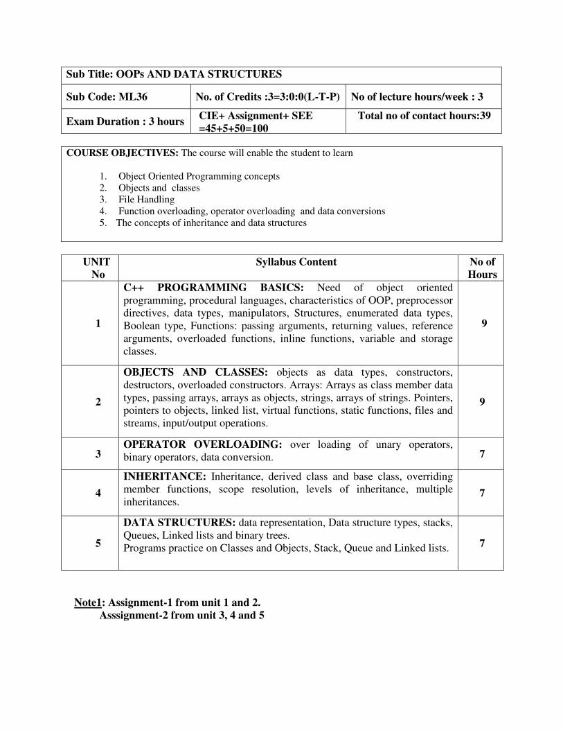
COURSE OBJECTIVES: The course will enable the student to learn
1. Object Oriented Programming concepts
2. Objects and classes
3. File Handling
4. Function overloading, operator overloading and data conversions
5. The concepts of inheritance and data structures
UNIT
No
Syllabus Content
No of
Hours
1
C++ PROGRAMMING BASICS: Need of object oriented
programming, procedural languages, characteristics of OOP, preprocessor
directives, data types, manipulators, Structures, enumerated data types,
Boolean type, Functions: passing arguments, returning values, reference
arguments, overloaded functions, inline functions, variable and storage
classes.
9
2
OBJECTS AND CLASSES: objects as data types, constructors,
destructors, overloaded constructors. Arrays: Arrays as class member data
types, passing arrays, arrays as objects, strings, arrays of strings. Pointers,
pointers to objects, linked list, virtual functions, static functions, files and
streams, input/output operations.
9
3 OPERATOR OVERLOADING: over loading of unary operators,
binary operators, data conversion. 7
4
INHERITANCE: Inheritance, derived class and base class, overriding
member functions, scope resolution, levels of inheritance, multiple
inheritances. 7
5
DATA STRUCTURES: data representation, Data structure types, stacks,
Queues, Linked lists and binary trees.
Programs practice on Classes and Objects, Stack, Queue and Linked lists. 7
Note1: Assignment-1 from unit 1 and 2.
Asssignment-2 from unit 3, 4 and 5
Sub Title: OOPs AND DATA STRUCTURES
Sub Code: ML36 No. of Credits :3=3:0:0(L-T-P) No of lecture hours/week : 3
Exam Duration : 3 hours CIE+ Assignment+ SEE
=45+5+50=100
Total no of contact hours:39
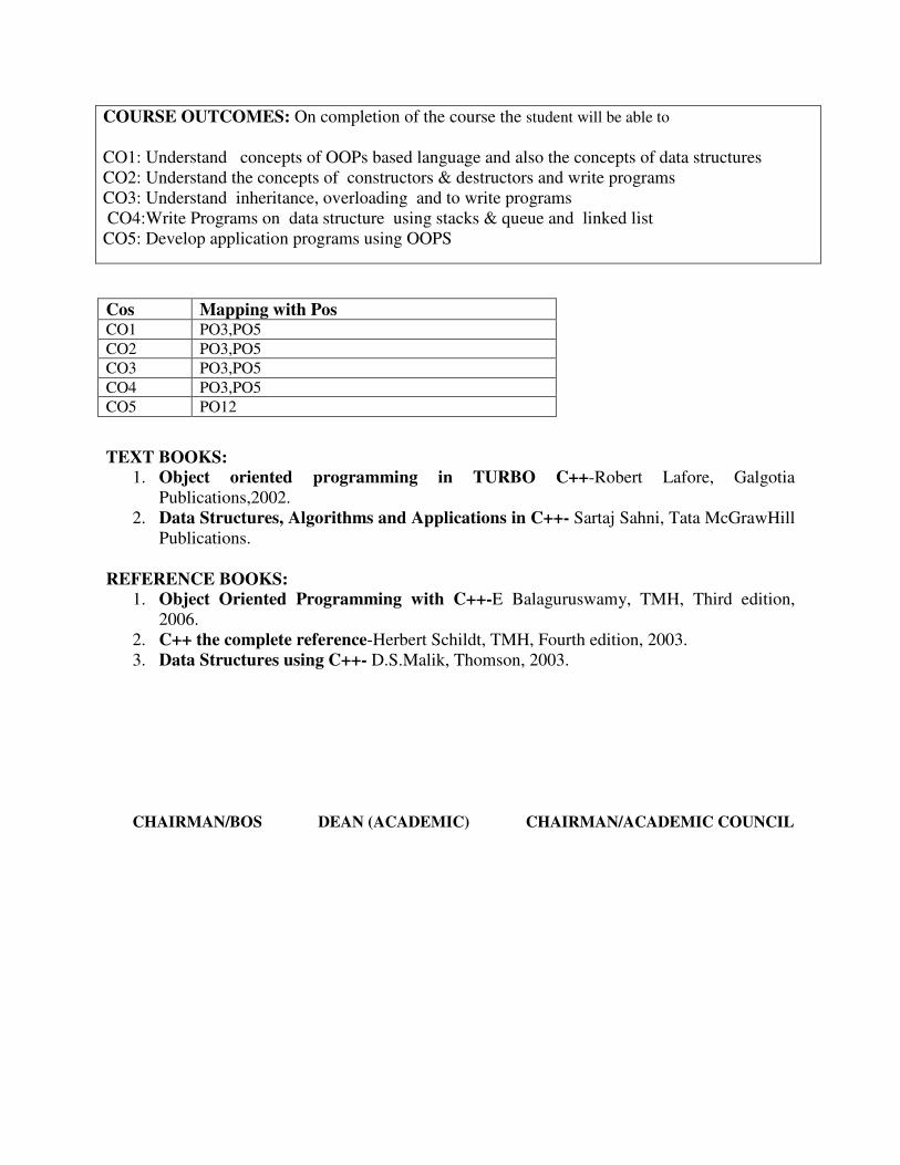
COURSE OUTCOMES: On completion of the course the student will be able to
CO1: Understand concepts of OOPs based language and also the concepts of data structures
CO2: Understand the concepts of constructors & destructors and write programs
CO3: Understand inheritance, overloading and to write programs
CO4:Write Programs on data structure using stacks & queue and linked list
CO5: Develop application programs using OOPS
TEXT BOOKS:
1. Object oriented programming in TURBO C++-Robert Lafore, Galgotia
Publications,2002.
2. Data Structures, Algorithms and Applications in C++- Sartaj Sahni, Tata McGrawHill
Publications.
REFERENCE BOOKS:
1. Object Oriented Programming with C++-E Balaguruswamy, TMH, Third edition,
2006.
2. C++ the complete reference-Herbert Schildt, TMH, Fourth edition, 2003.
3. Data Structures using C++- D.S.Malik, Thomson, 2003.
CHAIRMAN/BOS DEAN (ACADEMIC) CHAIRMAN/ACADEMIC COUNCIL
Cos Mapping with Pos
CO1 PO3,PO5
CO2 PO3,PO5
CO3 PO3,PO5
CO4 PO3,PO5
CO5 PO12
CHAIRMAN/BOS DEAN (ACADEMIC) CHAIRMAN/ACADEMIC COUNCIL
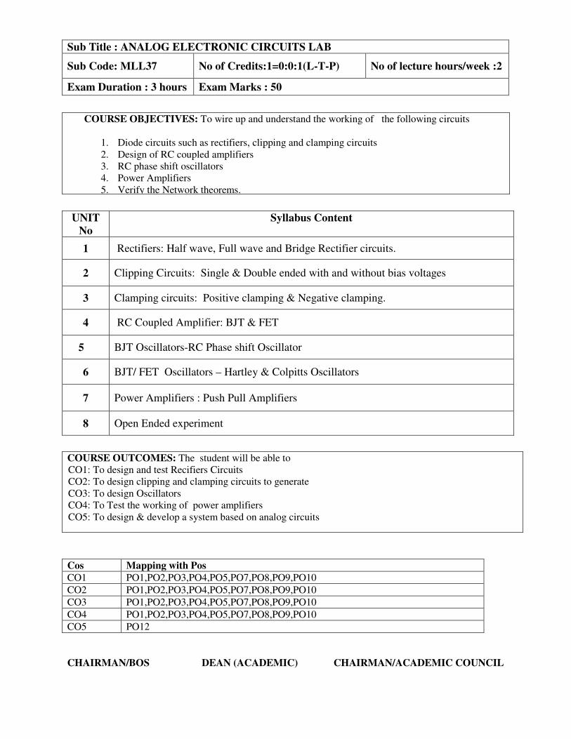
Sub Title : ANALOG ELECTRONIC CIRCUITS LAB
Sub Code: MLL37 No of Credits:1=0:0:1(L-T-P) No of lecture hours/week :2
Exam Duration : 3 hours Exam Marks : 50
COURSE OBJECTIVES: To wire up and understand the working of the following circuits
1. Diode circuits such as rectifiers, clipping and clamping circuits
2. Design of RC coupled amplifiers
3. RC phase shift oscillators
4. Power Amplifiers
5. Verify the Network theorems.
UNIT
No
Syllabus Content
1 Rectifiers: Half wave, Full wave and Bridge Rectifier circuits.
2 Clipping Circuits: Single & Double ended with and without bias voltages
3 Clamping circuits: Positive clamping & Negative clamping.
4 RC Coupled Amplifier: BJT & FET
5 BJT Oscillators-RC Phase shift Oscillator
6 BJT/ FET Oscillators – Hartley & Colpitts Oscillators
7 Power Amplifiers : Push Pull Amplifiers
8 Open Ended experiment
COURSE OUTCOMES: The student will be able to
CO1: To design and test Recifiers Circuits
CO2: To design clipping and clamping circuits to generate
CO3: To design Oscillators
CO4: To Test the working of power amplifiers
CO5: To design & develop a system based on analog circuits
Cos Mapping with Pos
CO1 PO1,PO2,PO3,PO4,PO5,PO7,PO8,PO9,PO10
CO2 PO1,PO2,PO3,PO4,PO5,PO7,PO8,PO9,PO10 CO3 PO1,PO2,PO3,PO4,PO5,PO7,PO8,PO9,PO10 CO4 PO1,PO2,PO3,PO4,PO5,PO7,PO8,PO9,PO10 CO5 PO12
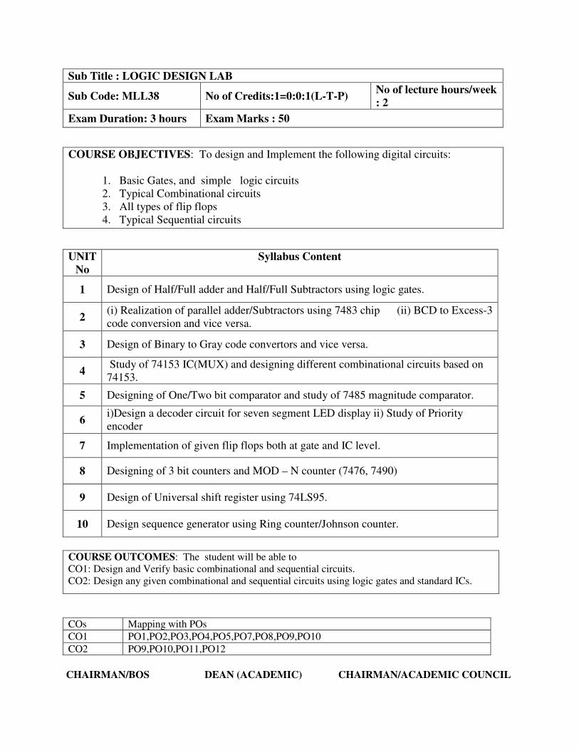
COURSE OUTCOMES: The student will be able to
CO1: Design and Verify basic combinational and sequential circuits.
CO2: Design any given combinational and sequential circuits using logic gates and standard ICs.
CHAIRMAN/BOS DEAN (ACADEMIC) CHAIRMAN/ACADEMIC COUNCIL
Sub Title : LOGIC DESIGN LAB
Sub Code: MLL38 No of Credits:1=0:0:1(L-T-P) No of lecture hours/week
: 2
Exam Duration: 3 hours Exam Marks : 50
COURSE OBJECTIVES: To design and Implement the following digital circuits:
1. Basic Gates, and simple logic circuits
2. Typical Combinational circuits
3. All types of flip flops
4. Typical Sequential circuits
UNIT
No
Syllabus Content
1 Design of Half/Full adder and Half/Full Subtractors using logic gates.
2 (i) Realization of parallel adder/Subtractors using 7483 chip (ii) BCD to Excess-3
code conversion and vice versa.
3 Design of Binary to Gray code convertors and vice versa.
4 Study of 74153 IC(MUX) and designing different combinational circuits based on
74153.
5 Designing of One/Two bit comparator and study of 7485 magnitude comparator.
6 i)Design a decoder circuit for seven segment LED display ii) Study of Priority
encoder
7 Implementation of given flip flops both at gate and IC level.
8 Designing of 3 bit counters and MOD – N counter (7476, 7490)
9 Design of Universal shift register using 74LS95.
10 Design sequence generator using Ring counter/Johnson counter.
COs Mapping with POs
CO1 PO1,PO2,PO3,PO4,PO5,PO7,PO8,PO9,PO10
CO2 PO9,PO10,PO11,PO12
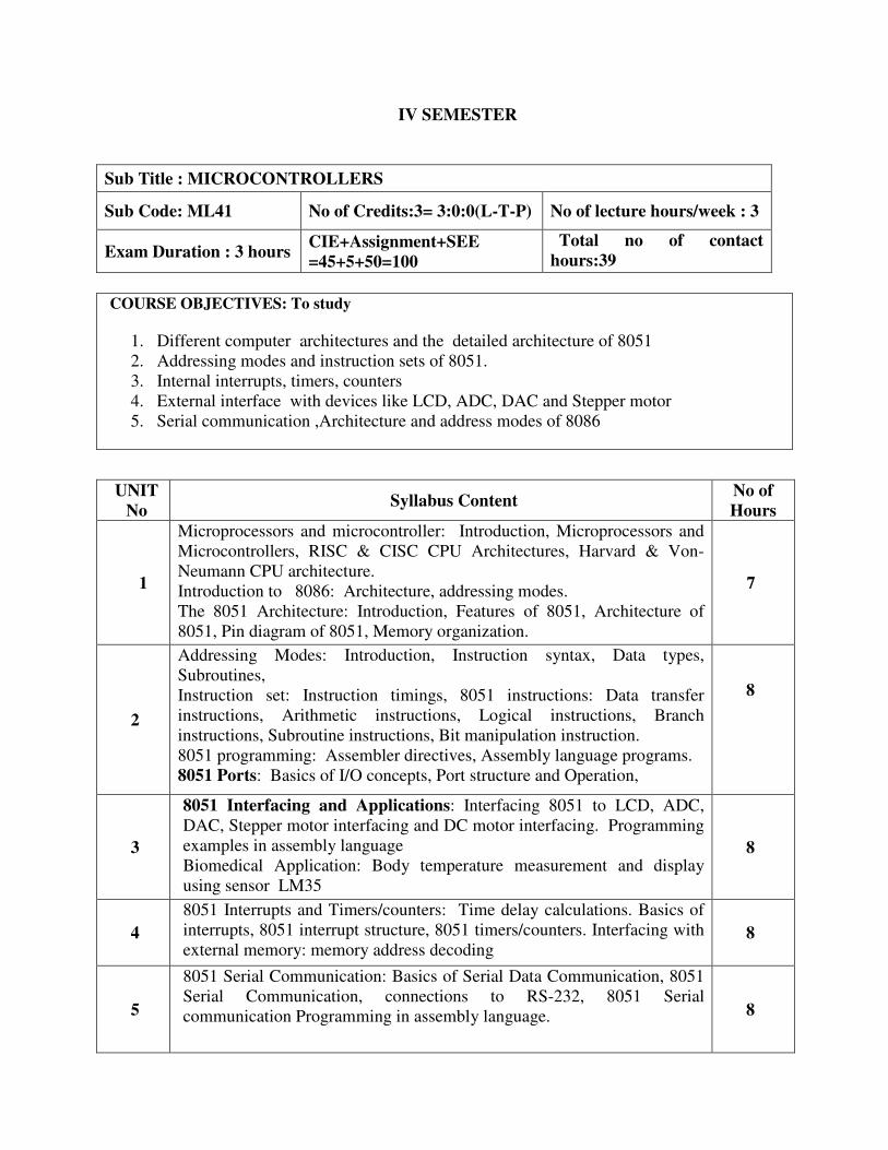
IV SEMESTER
Sub Title : MICROCONTROLLERS
Sub Code: ML41 No of Credits:3= 3:0:0(L-T-P) No of lecture hours/week : 3
Exam Duration : 3 hours CIE+Assignment+SEE
=45+5+50=100
Total no of contact
hours:39
COURSE OBJECTIVES: To study
1. Different computer architectures and the detailed architecture of 8051
2. Addressing modes and instruction sets of 8051.
3. Internal interrupts, timers, counters
4. External interface with devices like LCD, ADC, DAC and Stepper motor
5. Serial communication ,Architecture and address modes of 8086
UNIT
No Syllabus Content
No of
Hours
1
Microprocessors and microcontroller: Introduction, Microprocessors and
Microcontrollers, RISC & CISC CPU Architectures, Harvard & Von-
Neumann CPU architecture.
Introduction to 8086: Architecture, addressing modes.
The 8051 Architecture: Introduction, Features of 8051, Architecture of
8051, Pin diagram of 8051, Memory organization.
7
2
Addressing Modes: Introduction, Instruction syntax, Data types,
Subroutines,
Instruction set: Instruction timings, 8051 instructions: Data transfer
instructions, Arithmetic instructions, Logical instructions, Branch
instructions, Subroutine instructions, Bit manipulation instruction.
8051 programming: Assembler directives, Assembly language programs.
8051 Ports: Basics of I/O concepts, Port structure and Operation,
8
3
8051 Interfacing and Applications: Interfacing 8051 to LCD, ADC,
DAC, Stepper motor interfacing and DC motor interfacing. Programming
examples in assembly language
Biomedical Application: Body temperature measurement and display
using sensor LM35
8
4
8051 Interrupts and Timers/counters: Time delay calculations. Basics of
interrupts, 8051 interrupt structure, 8051 timers/counters. Interfacing with
external memory: memory address decoding 8
5
8051 Serial Communication: Basics of Serial Data Communication, 8051
Serial Communication, connections to RS-232, 8051 Serial
communication Programming in assembly language.
8

Note1: Assignment-1 from unit 1 and 2.
Asssignment-2 Interfacing applications
COURSE OUTCOMES: On the completion of the course the students will be able to
CO1: Compare & Differentiate different computer architectures
CO2: Identify the different addressing modes of 8051 & 8086
CO3:Write software programs using all the instructions of 8051
CO4:Design interface for ADC/DAC, LCD, Stepper & DC Motor and external memory with
8051
CO5: Incorporate the Timer, Interrupts and Serial Communication in developing application
programs.
Cos Mapping with Pos
CO1 PO2,PO3,PO5
CO2 PO3,PO5, PO12
CO3 PO3,PO5, PO12
CO4 PO4, PO5, PO12
CO5 PO4, PO5, PO12
TEXT BOOKS:
1. The 8051 Microcontroller and Embedded Systems – using assembly and C,
Muhammad Ali Mazidi and Janice Gillespie Mazidi and Rollin D. McKinlay, PHI,
2006.
2. 8051 Micrcontroller-Hardware, Software and Applications, V.Udayashankara and
M.S. Mallikarjunaswamy ,Tata McGraw-Hill, 2009.
Reference Books:
1. The 8051 Microcontroller and embedded systems, Kenneth J. Ayala and Dhananjay
V.Gadre , Cenegage learning.
2. Programming and Customizing the 8051 Microcontroller, Predko ,TMH.
3. Microcontrollers- Theory and Applications, Ajay V.Deshmukh ,TMH,2005.
4. Texas Instruments Manual LM35
CHAIRMAN/BOS DEAN (ACADEMIC) CHAIRMAN/ACADEMIC COUNCIL

COURSE OBJECTIVES: To make the students
1. Develop an understanding of the concept of a communication system.
2. To distinguish between amplitude and angle modulation.
3. Understand the signal to noise ratio and understand the SNR in different techniques.
4. To learn the concepts of sampling and quantization.
5. Be able to understand Digital Modulation Techniques.
UNIT
No
Syllabus Content
No of
Hours
1
AMPLITUDE MODULATION: Time-Domain Description,
Frequency domain description, Generation of AM waves, Detection of
AM waves, AM/DSB, Time-Domain Description, Frequency domain
description, Generation of DSBSC waves, Coherent Detection of DSBSC
Modulated waves. Costas loop, Quadrature Carrier multiplexing, AM-
SSBSC generation, Frequency - Domain Description, Frequency
discrimination method for generation an SSB Modulated wave, time
domain description and generation .
9
2
FREQUENCY MODULATION: Basic Concepts, Frequency
Modulation, Spectrum Analysis Of sinusoidal FM wave, NBFM, WBFM,
Constant Average power, Transmission bandwidth of FM waves,
Generation of FM waves, Direct FM, demodulation of FM waves,
frequency discriminator, ZCD.
8
3
NOISE IN ANALOG MODULATION: Signal to noise Ratio :AM
Receiver Model, DSBSC Receiver, SSB Receiver, FM Receiver Model,
Noise in FM Reception, FM Threshold effect, Pre-Emphasis and De-
Emphasis in FM.
7
4
DIGITAL MODULATION: Sampling theorem for low pass and band
pass signal, statement and proof, PAM, Natural Sampling, Flat-Top
sampling, Quantization of Signals, Quantization error.
PCM, Electrical representations of Binary digits, The PCM Systems,
DPCM, Delta Modulation, ADM, ASK, FSK
8
5
TELEMEDICINE: Introduction, A remote health monitoring system:
The concepts and the functions, example of system operation, Diagnostic
equipment: ECG and heart frequency monitoring, Blood glucose
monitoring, Physical activity monitoring, Breathing frequency
monitoring, oximetry monitoring, Arterial pressure monitoring, Body
temperature.
7
Note1: Assignment-1 from unit 1 and 2.
Asssignment-2 from unit 3, 4 and 5
Sub Title: COMMUNICATION SYSTEMS
Sub Code: ML42 No. of Credits:3=3:0:0(L-T-P) No of lecture hours/week :03
Exam Duration : 3 hours CIE+ Assignment+ SEE
=45+5+50=100
Total no of contact hours:39

COURSE OUTCOMES: On completion of the course the student will be able to
CO1: Understand the Amplitude and frequency modulation techniques.
CO2: Understand and derive SNR for AM & FM .
CO3: Understand digital modulation techniques
CO4: Applications of Communication in the field of telemedicine.
TEXT BOOKS:
1. Analog and Digital communication-Simon Haykin, John Willey, 2nd
edition.
2. Principles of communication systems, Taub and Schilling, TMH, 3rd
edition.
3. Innovative Medical Devices for Telemedecine Application , Agostino Giorgia.
REFERENCE BOOKS:
1. Electronic Communication Systems, Blake, Thomson , 2nd
Edition.
2. Communication Systems- Sam Shanmugam, John Wiley.
3. Contemporary Communication Systems using Matlab, Proakis ,Cengage Learning,
2nd
edition.
4. Electronic Communication Systems- George Kennedy.
CHAIRMAN/BOS DEAN (ACADEMIC) CHAIRMAN/ACADEMIC COUNCIL
COs Mapping with POs
CO1 PO1,PO3,PO4,PO7
CO2 PO1,PO3,PO4,PO7
CO3 PO3,PO4
CO4 PO3,PO4,PO12
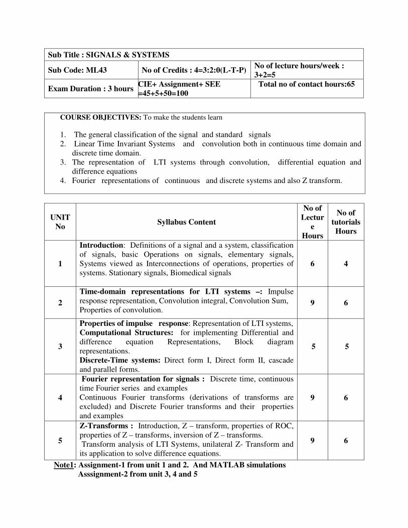
UNIT
No Syllabus Content
No of
Lectur
e
Hours
No of
tutorials
Hours
1
Introduction: Definitions of a signal and a system, classification
of signals, basic Operations on signals, elementary signals,
Systems viewed as Interconnections of operations, properties of
systems. Stationary signals, Biomedical signals
6 4
2
Time-domain representations for LTI systems –: Impulse
response representation, Convolution integral, Convolution Sum,
Properties of convolution.
9 6
3
Properties of impulse response: Representation of LTI systems,
Computational Structures: for implementing Differential and
difference equation Representations, Block diagram
representations.
Discrete-Time systems: Direct form I, Direct form II, cascade
and parallel forms.
5 5
4
Fourier representation for signals : Discrete time, continuous
time Fourier series and examples
Continuous Fourier transforms (derivations of transforms are
excluded) and Discrete Fourier transforms and their properties
and examples
9 6
5
Z-Transforms : Introduction, Z – transform, properties of ROC,
properties of Z – transforms, inversion of Z – transforms.
Transform analysis of LTI Systems, unilateral Z- Transform and
its application to solve difference equations.
9 6
Note1: Assignment-1 from unit 1 and 2. And MATLAB simulations
Asssignment-2 from unit 3, 4 and 5
Sub Title : SIGNALS & SYSTEMS
Sub Code: ML43 No of Credits : 4=3:2:0(L-T-P) No of lecture hours/week :
3+2=5
Exam Duration : 3 hours CIE+ Assignment+ SEE
=45+5+50=100
Total no of contact hours:65
COURSE OBJECTIVES: To make the students learn
1. The general classification of the signal and standard signals
2. Linear Time Invariant Systems and convolution both in continuous time domain and
discrete time domain.
3. The representation of LTI systems through convolution, differential equation and
difference equations
4. Fourier representations of continuous and discrete systems and also Z transform.
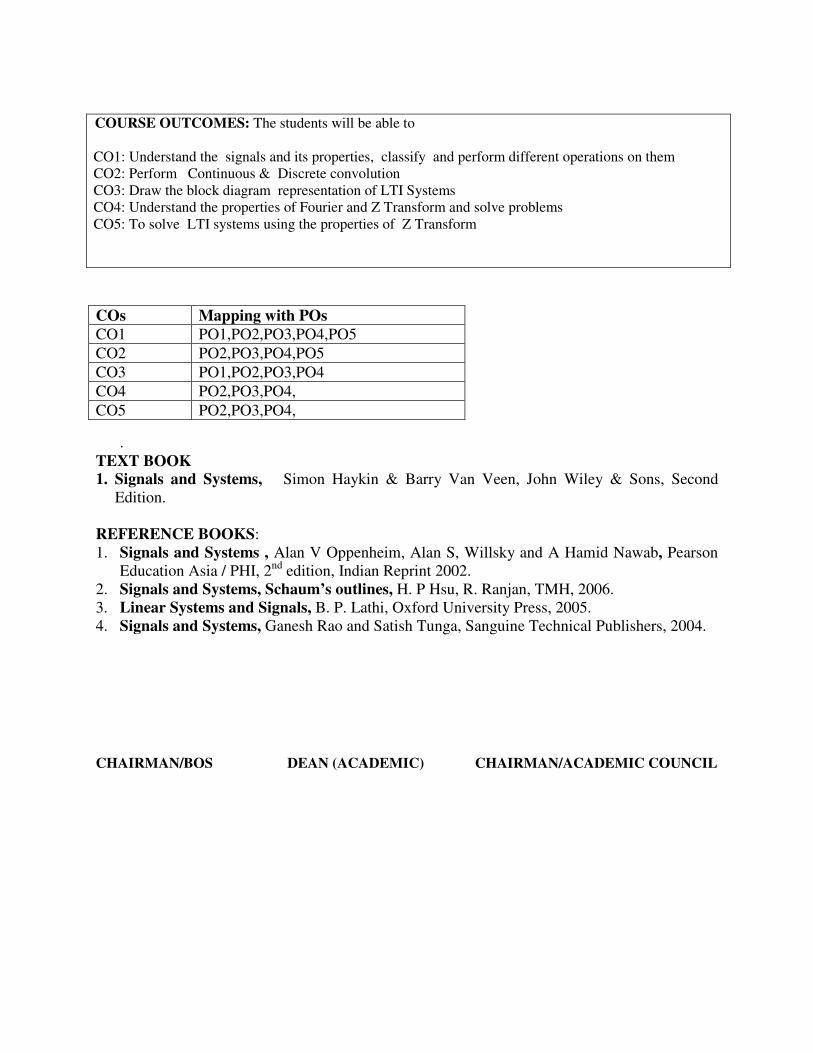
COURSE OUTCOMES: The students will be able to
CO1: Understand the signals and its properties, classify and perform different operations on them
CO2: Perform Continuous & Discrete convolution
CO3: Draw the block diagram representation of LTI Systems
CO4: Understand the properties of Fourier and Z Transform and solve problems
CO5: To solve LTI systems using the properties of Z Transform
.
TEXT BOOK
1. Signals and Systems, Simon Haykin & Barry Van Veen, John Wiley & Sons, Second
Edition.
REFERENCE BOOKS:
1. Signals and Systems , Alan V Oppenheim, Alan S, Willsky and A Hamid Nawab, Pearson
Education Asia / PHI, 2nd
edition, Indian Reprint 2002.
2. Signals and Systems, Schaum’s outlines, H. P Hsu, R. Ranjan, TMH, 2006.
3. Linear Systems and Signals, B. P. Lathi, Oxford University Press, 2005.
4. Signals and Systems, Ganesh Rao and Satish Tunga, Sanguine Technical Publishers, 2004.
CHAIRMAN/BOS DEAN (ACADEMIC) CHAIRMAN/ACADEMIC COUNCIL
COs Mapping with POs
CO1 PO1,PO2,PO3,PO4,PO5
CO2 PO2,PO3,PO4,PO5
CO3 PO1,PO2,PO3,PO4
CO4 PO2,PO3,PO4,
CO5 PO2,PO3,PO4,

COURSE OBJECTIVES: Is to make the student understand
1. The human physiology, anatomy and evolution of bio signals.
2. The concepts of bio signal transducers and measurement.
3. The working of all major biomedical equipments.
4. The safety of biomedical devices.
Unit
No. Syllabus Content
No. of
Hours
1
FUNDAMENTAL CONCEPTS: Sources of biomedical signals, Basic medical
instrumentation system, performance requirements of medical instrumentation
systems, General constraints in design of medical instrumentation systems.
Bioelectric Signals and Electrodes: Electrocardiogram (ECG),
Electroencephalogram (EEG), Electromyogram (EMG), Electrodes for ECG,
Electrodes for EEG, Electrodes of EMG. EOG, EGG.
10
2
BIO POTENTIAL AMPLIFIERS: Need for bio amplifier- single ended bio
amplifier-right leg driven ECG amplifier, Transient protection, Common-Mode and
Other Interference -Reduction Circuits, Amplifiers for other bio potential signals,
Band Pass filtering, isolation amplifiers-transformer and optical isolation- isolated
DC amplifier and AC carrier amplifier. Chopper amplifier. Power line interference.
10
3
BIOMEDICAL RECORDERS: Electrocardiograph-block diagram description,
ECG leads, artefacts, Vector cardiograph, Phonocardiograph,
Electroencephalograph, Electromyograph, measurement of heart rate, measurement
of pulse rate, blood pressure measurement, measurement of temperature,
measurement of respiratory rate.
12
4
OXIMETERS: Oximetry, ear oximeter, pulse oximeter, skin reflectance oximeter
and intravascular oximeter.
Cardiac Output Measurement: Indicator-Dilution Method- Continuous infusion,
Rapid injection.
Blood Flow Meters: Electromagnetic blood flow meters, Ultrasonic blood flow
meters, NMR blood flow meters, Photoplethysmography.
10
5
CARDIAC PACEMAKERS AND DEFIBRILLATORS: Need for cardiac
pacemaker, External pacemaker, Implantable pacemaker, Types of Implantable
pacemakers, Programmable pacemaker, Rate-responsive pacemakers. DC
defibrillator, Implantable defibrillators.
PATIENT SAFETY: Physiological effects of electrical currents on humans.
Electric shock hazards, Leakage currents, macro shock, micro shock hazards and
preventions, Electrical safety analyzer & precautions. Electrical safety codes
standards.
10
Note2: Assignment-1 from unit 1 and 2.
Asssignment-2 from unit 3, 4 and 5
Sub Title: BIOMEDICAL INSTRUMENTATION
Sub Code: ML44 No. of Credits : 4=4: 0: 0(L-T-P) No of lecture hours/week :04
Exam Duration : 3 hours CIE+ Assignment+ SEE =45+5+50=100 Total no of contact hours:52
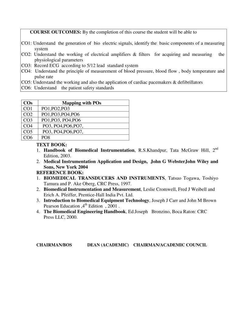
COURSE OUTCOMES: By the completion of this course the student will be able to
CO1: Understand the generation of bio electric signals, identify the basic components of a measuring
system
CO2: Understand the working of electrical amplifiers & filters for acquiring and measuring the
physiological parameters
CO3: Record ECG according to 5/12 lead standard system
CO4: Understand the principle of measurement of blood pressure, blood flow , body temperature and
pulse rate
CO5: Understand the working and also the application of cardiac pacemakers & defibrillators
CO6: Understand the patient safety standards
TEXT BOOK:
1. Handbook of Biomedical Instrumentation, R.S.Khandpur, Tata McGraw Hill, 2nd
Edition, 2003.
2. Medical Instrumentation Application and Design, John G WebsterJohn Wiley and
Sons, New York 2004
REFERENCE BOOK:
1. BIOMEDICAL TRANSDUCERS AND INSTRUMENTS, Tatsuo Togawa, Toshiyo
Tamura and P. Ake Oberg, CRC Press, 1997.
2. Biomedical Instrumentation and Measurement, Leslie Cromwell, Fred J Weibell and
Erich A. Pfeiffer, Prentice-Hall India Pvt. Ltd.
3. Introduction to Biomedical Equipment Technology, Joseph J Carr and John M Brown
Pearson Education ,4th
Edition , 2001 .
4. The Biomedical Engineering Handbook, Ed.Joseph Bronzino, Boca Raton: CRC
Press LLC, 2000.
CHAIRMAN/BOS DEAN (ACADEMIC) CHAIRMAN/ACADEMIC COUNCIL
COs Mapping with POs
CO1 PO1,PO2,PO3
CO2 PO1,PO3,PO4,PO6
CO3 PO1,PO3, PO4,PO6
CO4 PO3, PO4,PO6,PO7,
CO5 PO3, PO4,PO6,PO7,
CO6 PO8

COURSE OBJECTIVES:
1. This subject aims to give the students a complete understanding of operational
amplifiers,their characteristics, operating parameters and all arithmetic circuits built using
opamp.
2.The students will get to learn the qualitative and quantitative analysis of the following
application circuits: Amplifiers, waveform generators, precision rectifiers , filters ,timers
and their applications and A to D , D to A converters.
Note 1: Assignment-1 from unit 1 and 2.
Asssignment-2 from unit 3, 4 and 5
Sub Title : LINEAR IC’s AND APPLICATIONS
Sub Code: ML45 No. of Credits: 3=3:0:0(L-T-P) No of lecture hours/week : 3
Exam Duration : 3 hours CIE+ Assignment+ SEE
=45+5+50=100
Total no of contact hours:39
Unit
No
Syllabus Content No of
Hours
1
Operational Amplifier Fundamentals: Introduction, basic information of
op-amp , ideal operational amplifier, operational amplifier internal circuit,
IC741 op-amp circuit.
Operational Amplifier characteristics: Introduction, DC characteristics,
AC characteristics.
Introduction to TI simulation software : Toolkit for Interactive Network
Analysis(TINA)
8
2
Operational Amplifier applications: Introduction, basic op-amp
application, instrumentation amplifier, AC amplifier, V to I and I to V
converter, op-amp circuits using diodes, sample and hold circuit, log and
antilog amplifier, differentiator, integrator.
Simulation of various circuits using TINA (Demonstration only)
8
3
Comparators and Waveform generators: Introduction, comparator,
Schmitt trigger, astable multivibrator, monostable multivibrator, triangular
wave generator, oscillators. 7
4
Active filters: Introduction, first and second order low pass &high pass
filters.
555 Timer: Introduction, functional diagram, monostable, astable and
Schmitt trigger operations.
8
5
D-A and A-D converter: Introduction, DAC techniques: Specifications
Binary weighted resistor network, R-2R Ladder Network.
A-D converters: Specifications, Dual Slope converters, Flash Converters,
Successive Approximation
Mandatory assignment: Developing any application using simulation
software TINA.
8

COURSE OUTCOMES: On completion of the course the student will be able to
CO1: Design basic and complex circuits using the fundamental knowledge of op-amp
CO2: Build various op-amp application circuits
CO3: Determine various comparators usage and waveform generation techniques
CO4: Design of filters and 555 Timer.
CO5: Develop D-A and A-D converters
Text Books:
1. Linear Integrated Circuits, D. Roy Choudhury and Shail B. Jain, New Age International
3rd edition, 2010.
2. Op - Amps and Linear Integrated Circuits, Ramakant A. Gayakwad, PHI, 4 th edition.
Reference Books:
1. Operational Amplifiers and Linear Integrated Circuits, Robert. F. Coughlin & Fred.F.
Driscoll, PHI/Pearson, 2006.
2. Design with Operational Amplifiers and Analog Integrated Circuits, Sergio Franco,
TMH, 3e, 2005.
CHAIRMAN/BOS DEAN (ACADEMIC) CHAIRMAN/ACADEMIC COUNCIL
Cos Mapping with Pos
CO1 PO1,PO2,PO3,PO4,PO5,PO7
CO2 PO2,PO3,PO4,PO5,PO6,PO7
CO3 PO2,PO3,PO4,PO5,PO6, PO7
CO4 PO2,PO3,PO4,PO5,PO6, PO7
CO5 PO2,PO3,PO4,PO5,PO6, PO7
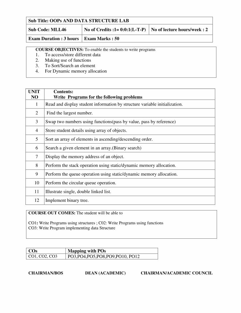
UNIT
NO
Contents:
Write Programs for the following problems
1 Read and display student information by structure variable initialization.
2 Find the largest number.
3 Swap two numbers using functions(pass by value, pass by reference)
4 Store student details using array of objects.
5 Sort an array of elements in ascending/descending order.
6 Search a given element in an array.(Binary search)
7 Display the memory address of an object.
8 Perform the stack operation using static/dynamic memory allocation.
9 Perform the queue operation using static/dynamic memory allocation.
10 Perform the circular queue operation.
11 Illustrate single, double linked list.
12 Implement binary tree.
COURSE OUT COMES: The student will be able to
CO1: Write Programs using structures ; C02: Write Programs using functions
CO3: Write Program implementing data Structure
CHAIRMAN/BOS DEAN (ACADEMIC) CHAIRMAN/ACADEMIC COUNCIL
Sub Title: OOPs AND DATA STRUCTURE LAB
Sub Code: MLL46 No of Credits :1= 0:0:1(L-T-P) No of lecture hours/week : 2
Exam Duration : 3 hours Exam Marks : 50
COURSE OBJECTIVES: To enable the students to write programs
1. To access/store different data
2. Making use of functions
3. To Sort/Search an element
4. For Dynamic memory allocation
COs Mapping with POs
CO1, CO2, CO3 PO3,PO4,PO5,PO8,PO9,PO10, PO12
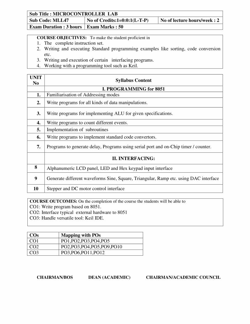
UNIT
No Syllabus Content
I. PROGRAMMING for 8051
1. Familiarisation of Addressing modes
2. Write programs for all kinds of data manipulations.
3. Write programs for implementing ALU for given specifications.
4. Write programs to count different events.
5. Implementation of subroutines
6. Write programs to implement standard code convertors.
7. Programs to generate delay, Programs using serial port and on-Chip timer / counter.
II. INTERFACING:
8
Alphanumeric LCD panel, LED and Hex keypad input interface
9 Generate different waveforms Sine, Square, Triangular, Ramp etc. using DAC interface
10 Stepper and DC motor control interface
COURSE OUTCOMES: On the completion of the course the students will be able to
CO1: Write program based on 8051.
CO2: Interface typical external hardware to 8051
CO3: Handle versatile tool: Keil IDE.
CHAIRMAN/BOS DEAN (ACADEMIC) CHAIRMAN/ACADEMIC COUNCIL
Sub Title : MICROCONTROLLER LAB
Sub Code: MLL47 No of Credits:1=0:0:1(L-T-P) No of lecture hours/week : 2
Exam Duration : 3 hours Exam Marks : 50
COURSE OBJECTIVES: To make the student proficient in
1. The complete instruction set.
2. Writing and executing Standard programming examples like sorting, code conversion
etc.
3. Writing and execution of certain interfacing programs.
4. Working with a programming tool such as Keil.
COs Mapping with POs
CO1 PO1,PO2,PO3,PO4,PO5
CO2 PO2,PO3,PO4,PO5,PO9,PO10
CO3 PO3,PO6,PO11,PO12

COURSE OBJECTIVES: The student will learn
1. To rig up ,test and verify the BASIC linear integrated circuits .
2. The application circuits such as filters, waveform generators, multivibrators.
Unit
No Syllabus Content
1. Study of Opamp characteristics.
2. Design of Inverting and non-inverting amplifier.
3.
Design of various application circuits of Opamp:
i)Adder and Subtractor
ii)Integrator iii)Differentiator.
4. Design Waveform generator using Schmitt trigger.
5. Design of active first order filter: Low pass, High Pass, Band pass, Band elimination.
6. Design of active second order filter: Low pass, High Pass, Band pass, Band elimination
7. Design of multivibrator using 555 timer.: i) Astable ii) Bistable
8. Building of PAM, PWM and PPM
9. Experiments on TI board
Open end experiment based on Telemedicine concepts.
CHAIRMAN/BOS DEAN (ACADEMIC) CHAIRMAN/ACADEMIC COUNCIL
Sub Title: LINEAR INTEGRATED CIRCUITS LAB
Sub Code: MLL48 No of Credits:1=0:0:1(L-T-P)
No of lecture hours/week :02
Exam Duration : 3 hours Exam Marks : 50
COURSE OUTCOME: The students will be able to
CO1: Design & Testing of linear circuits using opamp IC 741
CO2: Design & test Digital Communication Circuits Using 555
CO3: Build & test applications of 555 Timer IC
CO4: Realise different modules using Industry standard TI Board and develop application circuits
COs Mapping with Pos
CO1 PO2,PO3,PO4,PO5,PO7,PO9,PO10,P12
CO2 PO2,PO3,PO4,PO5,PO7,PO9,PO10,P12
CO3 PO2,PO3,PO4,PO5,PO7,PO9,PO10,P12
CO4 PO2,PO3,PO4,PO5,PO7,PO9,PO10,P12