subchapter j—electrical engineering · ... american bureau of shipping (abs), ... rules for...
TRANSCRIPT

184
SUBCHAPTER J—ELECTRICAL ENGINEERING
PART 110—GENERAL PROVISIONS
Subpart 110.01—Applicability
Sec. 110.01–1 General. 110.01–2 OMB control numbers assigned pur-
suant to the Paperwork Reduction Act. 110.01–3 Repairs and alterations. 110.01–4 Right of appeal.
Subpart 110.10—Reference Specifications, Standards, and Codes
110.10–1 Incorporation by reference.
Subpart 110.15—Terms Used in This Subchapter
110.15–1 Definitions.
Subpart 110.20—Equivalents
110.20–1 Equivalents.
Subpart 110.25—Plan Submittal
110.25–1 Plans and information required for new construction.
110.25–3 Procedure for submitting plans.
Subpart 110.30—Testing and Inspection
110.30–1 General. 110.30–3 Initial inspection. 110.30–5 Inspection for certification. 110.30–7 Repairs or alterations.
AUTHORITY: 33 U.S.C. 1509; 43 U.S.C 1333; 46 U.S.C. 3306, 3307, 3703; E.O. 12234, 45 FR 58801, 3 CFR, 1980 Comp., p. 277; Department of Homeland Security Delegation No. 0170.1; § 110.01–2 also issued under 44 U.S.C. 3507.
SOURCE: CGD 74–125A, 47 FR 15232, Apr. 8, 1982, unless otherwise noted.
Subpart 110.01—Applicability
§ 110.01–1 General. (a) This subchapter applies to all
electrical installations on vessels sub-ject to subchapters D, H, I, I-A, K, L, O, Q, R, T, U, and W of this chapter when-ever those subchapters require an elec-trical installation to be in accordance with this subchapter.
(b) This subchapter applies only to electrical installations contracted for after September 30, 1996.
(c) Installations and equipment ac-cepted by the Coast Guard as meeting
the applicable requirements in this subchapter in effect on the date the in-stallation was contracted for and which are maintained in good and serv-iceable condition to the satisfaction of the Officer in Charge, Marine Inspec-tion, may be continued in use until re-placement is ordered by the Officer in Charge, Marine Inspection, or as speci-fied in the regulations.
(d) [Reserved] (e) Electrical systems internal to a
pressure vessel for human occupancy (PVHO) need not meet the require-ments of this subchapter, but must meet the requirements of Subpart B (Commercial Diving Operations) of part 197 of this chapter.
[CGD 74–125A, 47 FR 15232, Apr. 8, 1982, as amended by CGD 94–108, 61 FR 28271, June 4, 1996]
§ 110.01–2 OMB control numbers as-signed pursuant to the Paperwork Reduction Act.
(a) Purpose. This section collects and displays the control numbers assigned to information collection and record-keeping requirements in this sub-chapter by the Office of Management and Budget (OMB) pursuant to the Pa-perwork Reduction Act of 1980 (44 U.S.C. 3501 et seq.). The Coast Guard in-tends that this section comply with the requirements of 44 U.S.C. 3507(f) which requires that agencies display a cur-rent control number assigned by the Director of the OMB for each approved agency information collection require-ment.
(b) Display.
46 CFR part or section where identified or described
Current OMB control No.
Subpart 110.25 .............................................. 1625–0031
[49 FR 38121, Sept. 27, 1984, as amended by USCG–2004–18884, 69 FR 58348, Sept. 30, 2004]
§ 110.01–3 Repairs and alterations.
(a) Repairs and replacements in kind must comply with either the regula-tions in this subchapter or those in ef-fect when the vessel was built.
VerDate Mar<15>2010 08:26 Nov 18, 2011 Jkt 223196 PO 00000 Frm 00194 Fmt 8010 Sfmt 8010 Y:\SGML\223196.XXX 223196wre
ier-
avile
s on
DS
K3T
PT
VN
1PR
OD
with
CF
R

185
Coast Guard, DHS § 110.10–1
(b) Alterations and modifications, such as re-engining, re-powering, up-grading of the main propulsion control system, or replacing extensive amounts of cabling, must comply with the regu-lations in this subchapter.
(c) Conversions specified in 46 U.S.C. 2101(14a), such as the addition of a midbody or a change in the service of the vessel, are handled on a case-by- case basis by the Commanding Officer, Marine Safety Center.
[CGD 94–108, 61 FR 28271, June 4, 1996, as amended at 62 FR 23906, May 1, 1997]
§ 110.01–4 Right of appeal. Any person directly affected by a de-
cision or action taken under this sub-chapter, by or on behalf of the Coast Guard, may appeal therefrom in ac-cordance with subpart 1.03 of this chap-ter.
[CGD 88–033, 54 FR 50380, Dec. 6, 1989]
Subpart 110.10—Reference Speci-fications, Standards, and Codes
§ 110.10–1 Incorporation by reference. (a) Certain material is incorporated
by reference into this subchapter with the approval of the Director of the Fed-eral Register under 5 U.S.C. 552(a) and 1 CFR part 51. To enforce any edition other than that specified in this sec-tion, the Coast Guard must publish no-tice of change in the FEDERAL REG-ISTER and the material must be avail-able to the public. The word ‘‘should,’’ when used in material incorporated by reference, is to be construed the same as the words ‘‘must’’ or ‘‘shall’’ for the purposes of this subchapter. All ap-proved material is available for inspec-tion at the National Archives and Records Administration (NARA). For information on the availability of this material at NARA, call 202–741–6030 or go to http://www.archives.gov/ federallregister/ codeloflfederallregulations/ ibrllocations.html. The material is also available for inspection at the U.S. Coast Guard, Office of Design and Engi-neering Standards (CG–521), 2100 2nd St. SW., Stop 7126, Washington, DC 20593– 7126, and is available from the sources listed below.
(b) American Bureau of Shipping (ABS), ABS Plaza, 16855 Northchase Drive, Houston, TX 77060:
(1) Rules for Building and Classing Steel Vessels, Part 4 Vessel Systems and Machinery (2003) (‘‘ABS Steel Ves-sel Rules’’), 110.15–1; 111.01–9; 111.12–3; 111.12–5; 111.12–7; 111.33–11; 111.35–1; 111.70–1; 111.105–31; 111.105–39; 111.105–40; 113.05–7; and
(2) Rules for Building and Classing Mobile Offshore Drilling Units, Part 4 Machinery and Systems (2001) (‘‘ABS MODU Rules’’), 111.12–1; 111.12–3; 111.12– 5; 111.12–7; 111.33–11; 111.35–1; 111.70–1.
(c) American National Standards Insti-tute (ANSI), 25 West 43rd Street, New York, NY 10036:
(1) ANSI/IEEE C37.12–1991, American National Standard for AC High-Voltage Circuit Breakers Rated on a Symmet-rical Current Basis-Specifications Guide (1991) (‘‘ANSI/IEEE C37.12’’), 111.54–1; and
(2) ANSI/IEEE C37.27–1987 (IEEE Std 331) Application Guide for Low-Voltage AC Nonintegrally Fused Power Circuitbreakers (Using Separately Mounted Current-Limiting Fuses) (1987) (‘‘ANSI/IEEE C37.27’’), 111.54–1;
(d) American Society of Mechanical En-gineers (ASME) International, Three Park Avenue, New York, NY 10016–5990:
(1) ASME A17.1–2000 Part 2 Electric Elevators (2000) (‘‘ASME A17.1’’), 111.91–1; and
(2) [Reserved] (e) ASTM International (formerly Amer-
ican Society for Testing and Materials) (ASTM), 100 Barr Harbor Drive, West Conshohocken, PA 19428–2959:
(1) ASTM B 117–97, Standard Practice for Operating Salt Spray (Fog) Appa-ratus (‘‘ASTM B 117’’), 110.15–1; and
(2) [Reserved] (f) Institute of Electrical and Electronic
Engineers IEEE), IEEE Service Center, 445 Hoes Lane, Piscataway, NJ 08854:
(1) IEEE Std C37.04–1999, IEEE Stand-ard Rating Structure for AC High-Volt-age Circuit Breakers (1999) (‘‘IEEE C37.04’’), 111.54–1;
(2) IEEE Std C37.010–1999 IEEE Appli-cation Guide for AC High-Voltage Cir-cuit Breakers Rated on a Symmetrical Current Basis (1999) (‘‘IEEE C37.010’’), 111.54–1;
(3) IEEE Std C37.13–1990 IEEE Stand-ard for Low-Voltage AC Power Circuit
VerDate Mar<15>2010 08:26 Nov 18, 2011 Jkt 223196 PO 00000 Frm 00195 Fmt 8010 Sfmt 8010 Y:\SGML\223196.XXX 223196wre
ier-
avile
s on
DS
K3T
PT
VN
1PR
OD
with
CF
R

186
46 CFR Ch. I (10–1–11 Edition) § 110.10–1
Breakers Used in Enclosures (Oct. 22, 1990) (‘‘IEEE C37.13’’), 111.54–1;
(4) IEEE Std C37.14–2002 IEEE Stand-ard for Low-Voltage DC Power Circuit Breakers Used in Enclosures (Apr. 25, 2003) (‘‘IEEE C37.14’’), 111.54–1;
(5) IEEE Std 45–1998 IEEE Rec-ommended Practice for Electric Instal-lations on Shipboard—1998 (Oct. 19, 1998) (‘‘IEEE 45–1998’’), 111.30–19; 111.105– 3; 111.105–31; 111.105–41;
(6) IEEE Std 45–2002 IEEE Rec-ommended Practice for Electrical In-stallations On Shipboard—2002 (Oct. 11, 2002) (‘‘IEEE 45–2002’’), 111.05–7; 111.15–2; 111.30–1; 111.30–5; 111.33–3; 111.33–5; 111.40–1; 111.60–1; 111.60–3; 111.60–5; 111.60–11; 111.60–13; 111.60–19; 111.60–21; 111.60–23; 111.75–5; 113.65–5;
(7) IEEE 100, The Authoritative Dic-tionary of IEEE Standards Terms, Sev-enth Edition (2000) (‘‘IEEE 100’’), 110.15– 1;
(8) [Reserved] (9) IEEE Std 1202–1991, IEEE Stand-
ard for Flame Testing of Cables for Use in Cable Tray in Industrial and Com-mercial Occupancies (May 29, 1991) (‘‘IEEE 1202’’), 111.60–6; 111.107–1; and
(10) IEEE Std 1580–2001, IEEE Rec-ommended Practice for Marine Cable for Use on Shipboard and Fixed or Floating Platforms (Dec. 17, 2001) (‘‘IEEE 1580’’), 111.60–1; 111.60–2; 111.60– 3.
(g) International Electrotechnical Com-mission (IEC), 3 Rue de Varembe, Gene-va, Switzerland:
(1) IEC 68–2–52, Environmental Test-ing Part 2: Tests—Test Kb: Salt Mist, Cyclic (Sodium Chloride Solution), Second Edition (1996) (‘‘IEC 68–2–52’’), 110.15–1;
(2) IEC 60331–11 Tests for electric ca-bles under fire conditions—Circuit in-tegrity—Part 11: Apparatus—Fire alone at a flame temperature of at least 750 °C, First Edition (1999) (‘‘IEC 60331–11’’), 113.30–25;
(3) IEC 60331–21 Tests for Electric Ca-bles Under Fire Conditions—Circuit In-tegrity—Part 21: Procedures and Re-quirements—Cables of Rated Voltage up to and Including 0.6/1.0kV, First Edi-tion (1999) (‘‘IEC 60331–21’’), 113.30–25;
(4) IEC 332–1 Tests on Electric Cables Under Fire Conditions, Part 1: Test on a Single Vertical Insulated Wire or
Cable, Third Edition (1993) (‘‘IEC 332– 1’’), 111.30–19;
(5) IEC 60332–3–22 Tests on Electric Cables Under Fire Conditions—Part 3– 22: Test for Vertical Flame Spread of Vertically-Mounted Bunched Wires or Cables—Category A, First Edition (2000) (‘‘IEC 60332–3–22’’), 111.60–1; 111.60–2; 111.60–6; 111.107–1;
(6) IEC 60079–0 Electrical apparatus for Explosive Gas Atmospheres—Part 0: General Requirements (Edition 3.1) (2000) (‘‘IEC 60079–0’’), 111.105–1; 111.105– 3; 111.105–5; 111.105–7; 111.105–17;
(7) IEC 60079–1 Electrical Apparatus for Explosive Gas Atmospheres—Part 1: Flameproof Enclosures ‘‘d’’ including corr.1, Fourth Edition (June 2001) (‘‘IEC 60079–1’’), 111.105–1; 111.105–3; 111.105–5; 111.105–7; 111.105–9; 111.105–17;
(8) IEC 60079–2 Electrical Apparatus for Explosive Gas Atmospheres—Part 2: Pressurized Enclosures ‘‘p’’, Fourth Edition (2001) (‘‘IEC 60079–2’’), 111.105–1; 111.105–3; 111.105–5; 111.105–7; 111.105–17;
(9) IEC 60079–5 Electrical Apparatus for Explosive Gas Atmospheres—Part 5: Powder Filling ‘‘q’’, Second Edition (1997) (‘‘IEC 60079–5’’), 111.105–1; 111.105– 3; 111.105–5; 111.105–7; 111.105–15; 111.105– 17;
(10) IEC 79–6 Electrical Apparatus for Explosive Gas Atmospheres—Part 6: Oil Immersion ‘‘o’’, Second Edition (1995) (‘‘IEC 79–6’’), 111.105–1; 111.105–3; 111.105–5; 111.105–7; 111.105–15; 111.105–17;
(11) IEC 60079–7 Electrical Apparatus for Explosive Gas Atmospheres—Part 7: Increased Safety ‘‘e’’, Third Edition (2001) (‘‘IEC 60079–7’’), 111.105–1; 111.105– 3; 111.105–5; 111.105–7; 111.105–15; 111.105– 17;
(12) IEC 60079–11 Electrical Apparatus for Explosive Gas Atmospheres—Part 11: Intrinsic Safety ‘‘i’’, Fourth Edition (1999) (‘‘IEC 60079–11’’), 111.105–1; 111.105–3; 111.105–5; 111.105–7; 111.105–11; 111.105–17;
(13) IEC 60079–15 Electrical Apparatus for Explosive Gas Atmospheres—Part 15: Type of Protection ‘‘n’’, Second Edi-tion (2001) (‘‘IEC 60079–15’’), 111.105–1; 111.105–3; 111.105–5; 111.105–7; 111.105–15; 111.105–17;
(14) IEC 79–18 Electrical Apparatus for Explosive Gas Atmospheres—Part 18: Encapsulation ‘‘m’’, First Edition (1992) (‘‘IEC 79–18’’), 111.105–1; 111.105–3; 111.105–5; 111.105–7; 111.105–15; 111.105–17;
VerDate Mar<15>2010 08:26 Nov 18, 2011 Jkt 223196 PO 00000 Frm 00196 Fmt 8010 Sfmt 8010 Y:\SGML\223196.XXX 223196wre
ier-
avile
s on
DS
K3T
PT
VN
1PR
OD
with
CF
R

187
Coast Guard, DHS § 110.10–1
(15) IEC 60092–101 Electrical Installa-tion in Ships, Part 101: Definitions and General Requirements, Edition 4.1 (2002) (‘‘IEC 60092–101’’), 110.15–1; 111.81– 1;
(16) IEC 92–201 Electrical Installation in Ships, Part 201: System Design-Gen-eral, Fourth Edition (1994) (‘‘IEC 92– 201’’), 111.70–3; 111.81–1;
(17) IEC 92–202 Amendment 1 Elec-trical Installation in Ships, Part 202: System Design-Protection (1996) (‘‘IEC 92–202’’), 111.12–7; 111.50–3; 111.53–1; 111.54–1;
(18) IEC 92–301 Amendment 2 Elec-trical Installation in Ships, Part 301: Equipment-Generators and Motors, (1995) (‘‘IEC 92–301’’), 111.12–7; 111.25–5; 111.70–1;
(19) IEC 60092–302 Electrical Installa-tion in Ships, Part 302: Low-Voltage Switchgear and Control Gear Assem-blies, Fourth Edition (1997) (‘‘IEC 60092– 302’’), 111.30–1; 111.30–5; 111.30–19;
(20) IEC 92–303 Electrical Installation in Ships, Part 303: Equipment-Trans-formers for Power and Lighting, Third Edition (1980) (‘‘IEC 92–303’’), 111.20–15;
(21) IEC 92–304 Amendment 1 Elec-trical Installation in Ships, Part 304: Equipment-Semiconductor Convertors (1995) (‘‘IEC 92–304’’), 111.33–3; 111.33–5;
(22) IEC 92–306 Electrical Installation in Ships, Part 306: Equipment-Lumi-naries and accessories, Third Edition (1980) (‘‘IEC 92–306’’), 111.75–20; 111.81–1;
(23) IEC 60092–352 Electrical Installa-tion in Ships—Choice and Installation of Cables for Low-Voltage Power Sys-tems, Second Edition (1997) (‘‘IEC 60092–352’’), 111.60–3; 111.60–5; 111.81–1;
(24) IEC 92–353 Electrical Installa-tions in Ships—Part 353: Single and Multicore Non-Radial Field Power Ca-bles with Extruded Solid Insulation for Rated Voltages 1kV and 3kV, Second Edition (1995) (‘‘IEC 92–353’’), 111.60–1; 111.60–3; 111.60–5;
(25) IEC 92–401 Electrical Installa-tions in Ships, Part 401: Installation and Test of completed Installation with amendment 1 (1987) and amend-ment 2 (1997), Third Edition (1980) (‘‘IEC 92–401’’), 111.05–9; 111.81–1;
(26) IEC 60092–502 Electrical Installa-tion in Ships, Part 502: Tankers—Spe-cial Features (1999) (‘‘IEC 60092–502’’), 111.81–1; 111.105–31;
(27) IEC 92–503 Electrical installa-tions in ships, Part 503: Special fea-tures: A.C. supply systems with voltages in the range of above 1kV up to and including 11kV, First Edition (1975) (‘‘IEC 92–503’’), 111.30–5;
(28) IEC 60529 Degrees of Protection Provided by Enclosures (IP Code), Edi-tion 2.1 (2001) (‘‘IEC 60529’’), 110.15–1; 111.01–9; 113.10–7; 113.20–3; 113.25–11; 113.30–25; 113.37–10; 113.40–10; 113.50–5;
(29) IEC 60533 Electrical and Elec-tronic Installations in Ships—Electro-magnetic Compatibility, Second Edi-tion (1999) (‘‘IEC 60533’’), 113.05–7;
(30) IEC 60947–2 Low-Voltage Switchgear and Controlgear Part 2: Circuit-Breakers, Third Edition (2003) (‘‘IEC 60947–2’’), 111.54–1;
(31) IEC 61363–1 Electrical Installa-tions of Ships and Mobile and Fixed Offshore Units—Part 1: Procedures for Calculating Short-Circuit Currents in Three-Phase a.c., First Edition (1998) (‘‘IEC 61363–1’’), 111.52–5; and
(32) IEC 62271–100, High-voltage switchgear and controlgear—part 100: High-voltage alternating current circuitbreakers, Edition 1.1 (2003) (‘‘IEC 62271–100’’), 111.54–1.
(h) International Maritime Organiza-tion (IMO), Publications Section, 4 Al-bert Embankment, London SE1 7SR, United Kingdom:
(1) International Convention for the Safety of Life at Sea (SOLAS), Consoli-dated Text of the International Con-vention for the Safety of Life at Sea, 1974, and its Protocol of 1988: Article, Annexes and Certificates. (Incor-porating all Amendments in Effect from January 2001) (2001) (‘‘IMO SOLAS 74’’), 111.99–5; 111.105–31; 112.15–1; 113.25– 6.
(i) International Society for Measure-ment and Control (ISA), 67 Alexander Drive, P.O. Box 12277, Research Tri-angle Park, NC 27709:
(1) RP 12.6, Wiring Practices for Haz-ardous (Classified) Locations Instru-mentation Part I: Intrinsic Safety, 1995 (‘‘ISA RP 12.6’’), 111.105–11; and
(2) [Reserved] (j) Lloyd’s Register, 71 Fenchurch
Street, London EC3M 4BS, Type Ap-proval System-Test Specification Num-ber 1 (2002), 113.05–7.
VerDate Mar<15>2010 08:26 Nov 18, 2011 Jkt 223196 PO 00000 Frm 00197 Fmt 8010 Sfmt 8010 Y:\SGML\223196.XXX 223196wre
ier-
avile
s on
DS
K3T
PT
VN
1PR
OD
with
CF
R

188
46 CFR Ch. I (10–1–11 Edition) § 110.10–1
(k) National Electrical Manufacturers Association (NEMA), 1300 North 17th Street, Arlington, VA 22209:
(1) NEMA Standards Publication ICS 2–2000, Industrial Control and Systems Controllers, Contactors, and Overload Relays, Rated 600 Volts (2000) (‘‘NEMA ICS 2’’), 111.70–3;
(2) NEMA Standards Publication ICS 2.3–1995, Instructions for the Handling, Installation, Operation, and Mainte-nance of Motor Control Centers Rated not More Than 600 Volts (1995) (‘‘NEMA ICS 2.3’’), 111.70–3;
(3) NEMA Standards Publication No. ICS 2.4–2003, NEMA and IEC Devices for Motor Service—a Guide for Under-standing the Differences (2003) (‘‘NEMA ICS 2.4’’), 111.70–3;
(4) NEMA Standards Publication No. ANSI/NEMA 250–1997, Enclosures for Electrical Equipment (1000 Volts Max-imum) (Aug. 30, 2001) (‘‘NEMA 250’’), 110.15–1; 111.01–9; 110.15–1; 113.10–7; 113.20–3; 113.25–11; 113.30–25; 113.37–10; 113.40–10; 113.50–5;
(5) NEMA Standards Publication No. WC–3–1992, Rubber Insulated Wire and Cable for the Transmission and Dis-tribution of Electrical Energy, Revi-sion 1, February 1994 (‘‘NEMA WC–3’’), 111.60–13; and
(6) NEMA WC–70/ICEA S–95–658–1999 Standard for Non-Shielded Power Rated Cable 2000V or Less for the Dis-tribution of Electrical Energy (1999) (‘‘NEMA WC–70’’), 111.60–13.
(l) National Fire Protection Association (NFPA), 1 Batterymarch Park, Quincy, MA 02169:
(1) NEC 2002 (NFPA 70), National Electrical Code Handbook, Ninth Edi-tion (2002) (‘‘NFPA NEC 2002’’), 111.05– 33; 111.20–15; 111.25–5; 111.50–3; 111.50–7; 111.50–9; 111.53–1; 111.54–1; 111.55–1; 111.59–1; 111.60–7; 111.60–13; 111.60–23; 111.81–1; 111.105–1; 111.105–3; 111.105–5; 111.105–7; 111.105–9; 111.105–15; 111.105–17; 111.107–1;
(2) NFPA 77, Recommended Practice on Static Electricity (2000) (‘‘NFPA 77’’), 111.105–27;
(3) NFPA 99, Standard for Health Care Facilities (2005) (‘‘NFPA 99’’), 111.105–37; and
(4) NFPA 496, Standard for Purged and Pressurized Enclosures for Elec-trical Equipment (2003) (‘‘NFPA 496’’), 111.105–7.
(m) Naval Publications and Forms Cen-ter (NPFC), Department of Defense, Single Stock Point, 700 Robins Avenue, Philadelphia, PA 19111:
(1) MIL–C–24640A, Military Specifica-tion Cables, Light Weight, Electric, Low Smoke, for Shipboard Use, Gen-eral Specification for (1995) Supple-ment 1 (June 26, 1995) (‘‘NPFC MIL–C– 24640A’’), 111.60–1; 111.60–3;
(2) MIL–C–24643A, Military Specifica-tion Cables and Cords, Electric, Low Smoke, for Shipboard Use, General Specification for (1996) Amendment 2 (Mar. 13, 1996) (‘‘NPFC MIL–C–24643A’’), 111.60–1; 111.60–3; and
(3) MIL–W–76D, Military Specifica-tion Wire and Cable, Hook-Up, Elec-trical, Insulated, General Specification for (2003) (Revision of MIL–W–76D–1992) Amendment 1–2003 (Feb. 6, 2003) (‘‘NPFC MIL–W–76D’’), 111.60–11.
(n) Naval Sea Systems Command (NAVSEA), Code 55Z, Department of the Navy, Washington, DC 20362:
(1) DDS 300–2, A.C. Fault Current Cal-culations, 1988 (‘‘NAVSEA DDS 300–2’’), 111.52–5; and
(2) MIL–HDBK–299(SH), Military Handbook Cable Comparison Handbook Data Pertaining to Electric Shipboard Cable Notice 1–1991 (Revision of MIL– HDBK–299(SH) (1989)) (Oct. 15, 1991) (‘‘NAVSEA MIL–HDBK–299(SH)’’), 111.60–3; and
(3) [Reserved] (o) Underwriters Laboratories Inc.
(UL), 12 Laboratory Drive, Research Triangle Park, NC 27709–3995:
(1) UL 44, Standard for Thermoset-In-sulated Wire and Cable, Fifteenth Edi-tion, Mar. 22, 1999 (Revisions through and including May 13, 2002) (‘‘UL 44’’), 111.60–11;
(2) UL 50, Standard for Safety Enclo-sures for Electrical Equipment, Elev-enth Edition (Oct. 19, 1995) (‘‘UL 50’’), 111.81–1;
(3) UL 62, Standard for Flexible Cord and Fixture Wire, Sixteenth Edition (Oct. 15, 1997) (‘‘UL 62’’), 111.60–13;
(4) UL 83, Standard for Thermo-plastic-Insulated Wires and Cables, Twelfth Edition (Sep. 29, 1998) (‘‘UL 83’’), 111.60–11;
(5) UL 484, Standard for Room Air Conditioners, Seventh Edition, Apr. 27, 1993 (Revisions through and including Sep. 3, 2002) (‘‘UL 484’’), 111.87–3;
VerDate Mar<15>2010 08:26 Nov 18, 2011 Jkt 223196 PO 00000 Frm 00198 Fmt 8010 Sfmt 8010 Y:\SGML\223196.XXX 223196wre
ier-
avile
s on
DS
K3T
PT
VN
1PR
OD
with
CF
R

189
Coast Guard, DHS § 110.15–1
(6) UL 489, Molded-Case Circuit Breakers, Molded-Case Switches, and Circuit-Breaker Enclosures, Ninth Edi-tion, Oct. 31, 1996 (Revisions through and including Mar. 22, 2000) (‘‘UL 489’’), 111.01–15; 111.54–1;
(7) UL 514A, Metallic Outlet Boxes, Ninth Edition (Dec. 27, 1996) (‘‘UL 514A’’), 111.81–1;
(8) UL 514B, Conduit, Tubing, and Cable Fittings, Fourth Edition (Nov. 3, 1997) (‘‘UL 514B’’), 111.81–1;
(9) UL 514C, Standard for Non-metallic Outlet Boxes, Flush-Device Boxes, and Covers, Second Edition (Oct. 31, 1988) (‘‘UL 514C’’), 111.81–1;
(10) UL 913, Standard for Intrinsically Safe Apparatus and Associated Appa-ratus for Use in Class i, ii, and iii, Divi-sion 1, Hazardous (Classified) Loca-tions, Sixth Edition, Aug. 8, 2002 (Revi-sions through and including Dec. 15, 2003) (‘‘UL 913’’), 111.105–11;
(11) UL 1042, Standard for Electric Baseboard Heating Equipment (Apr. 11, 1994) (‘‘UL 1042’’), 111.87–3;
(12) UL 1072, Standard for Medium- Voltage Power Cables, Third Edition, Dec. 28, 2001 (Revisions through and in-cluding Apr. 14, 2003) (‘‘UL 1072’’), 111.60–1;
(13) UL 1104, Standard for Marine Navigation Lights, 1998 (‘‘UL 1104’’), 111.75–17;
(14) UL 1203, Standard for Explosion- Proof and Dust-Ignition-Proof Elec-trical Equipment for Use in Hazardous (Classified) Locations, Third Edition, Sep. 7, 2000 (Revisions through and in-cluding Apr. 30, 2004) (‘‘UL 1203’’), 111.105–9;
(15) UL 1309, Marine Shipboard Ca-bles, First Edition (July 14, 1995) (‘‘UL 1309’’), 111.60–1; 111.60–3;
(16) UL 1581 (May 6, 2003) (‘‘UL 1581’’), 111.30–19; 111.60–2; 111.60–6;
(17) UL 1598, Luminaires, First Edi-tion (Jan. 31, 2000) (‘‘UL 1598’’): 111.75– 20; and
(18) UL 1598A, Standard for Supple-mental Requirements for Luminaires for Installation on Marine Vessels, First Edition (Dec. 4, 2000) (‘‘UL 1598A’’), 111.75–20.
[USCG–2003–16630, 73 FR 65193, Oct. 31, 2008, as amended by USCG–2009–0702, 74 FR 49234, Sept. 25, 2009]
Subpart 110.15—Terms Used in This Subchapter
§ 110.15–1 Definitions. As used in this subchapter— (a) The electrical and electronic
terms are defined in IEEE 100 or IEC 60092–101 (both incorporated by ref-erence; see 46 CFR 110.10–1).
(b) In addition to the definitions in paragraph (a) of this section—
Coastwise Vessel means a vessel that normally navigates the waters of any ocean or the Gulf of Mexico 20 nautical miles or less offshore and is certifi-cated for coastwise navigation by the Coast Guard.
Commandant means the Commandant of the Coast Guard.
Corrosion resistant material or finish means any material or finish that meets the testing requirements of ASTM B 117 (incorporated by reference; see 46 CFR 110.10–1) or test Kb in IEC 68–2–52 (incorporated by reference, see 46 CFR 110.10–1) for 200 hours and does not show pitting, cracking, or other de-terioration more severe than that re-sulting from a similar test on passivated AISI Type 304 stainless steel.
Corrosive location means a location exposed to the weather on vessels oper-ating in salt water or a location on board which may be exposed to the cor-rosive effects of the cargo carried or of the vessel’s systems.
Dead ship condition is the condition in which the main propulsion plant, boil-ers and auxiliaries are not in operation due to the absence of power.
Dripproof means enclosed so that equipment meets at least a NEMA 250 (incorporated by reference; see 46 CFR 110.10–1) Type 1 with dripshield, Type 2, or Type 12; or IEC 60529 (incorporated by reference; see 46 CFR 110.10–1) IP 22 rating.
Embarkation station means a location from which persons embark into sur-vival craft or are assembled before em-barking into survival craft.
Emergency squad means the crew des-ignated on the station bill as the nu-cleus of a damage control party.
Flashpoint means the minimum tem-perature at which a liquid gives off a vapor in sufficient concentration to form an ignitable mixture with air
VerDate Mar<15>2010 08:26 Nov 18, 2011 Jkt 223196 PO 00000 Frm 00199 Fmt 8010 Sfmt 8010 Y:\SGML\223196.XXX 223196wre
ier-
avile
s on
DS
K3T
PT
VN
1PR
OD
with
CF
R

190
46 CFR Ch. I (10–1–11 Edition) § 110.20–1
near the surface of the liquid, as speci-fied by the appropriate test procedure and apparatus.
Great Lakes vessel means a vessel that navigates exclusively on the Great Lakes and their connecting and tribu-tary waters.
Independent laboratory means a lab-oratory that is accepted by the Com-mandant under part 159 of this chapter for the testing and listing or certifi-cation of electrical equipment.
Location not requiring an exceptional degree of protection means a location which is not exposed to the environ-mental conditions outlined in the defi-nition for locations requiring excep-tional degrees of protection. This loca-tion requires the degree of protection of § 111.01–9 (c) or (d) of this chapter. These locations include—
(1) An accommodation space; (2) A dry store room; (3) A passageway adjacent to quar-
ters; (4) A water closet without a shower
or bath; (5) A radio, gyro and chart room; and (6) A location with similar environ-
mental conditions. Location requiring an exceptional de-
gree of protection means a location ex-posed to weather, seas, splashing, pres-sure-directed liquids, or similar mois-ture conditions. These locations in-clude—
(1) On deck; (2) A machinery space; (3) A cargo space; (4) A location within a galley or pan-
try area, laundry, or water closet which contains a shower or bath; and
(5) Other spaces with similar environ-mental conditions.
Marine inspector or inspector means a civilian employee or military member of the Coast Guard assigned by an Offi-cer in Charge, Marine Inspection, or the Commandant to perform duties with respect to the inspection, enforce-ment, and administration of vessel safety and navigation laws and regula-tions.
Nonsparking fan means nonsparking fan as defined in ABS Steel Vessel Rules (incorporated by reference; see 46 CFR 110.10–1), section 4–8–3/11.
Ocean vessel means a vessel that navi-gates the waters of any ocean or the
Gulf of Mexico more than 20 nautical miles offshore and is certificated by the Coast Guard for ocean navigation.
Qualified person means a person who by virtue of that person’s knowledge, ability, experience, specialized train-ing, or licensing can competently and safely perform required electrical du-ties or functions.
Waterproof means watertight; except that, moisture within or leakage into the enclosure is allowed if it does not interfere with the operation of the equipment enclosed. In the case of a generator or motor enclosure, water-proof means watertight; except that, leakage around the shaft may occur if the leakage is prevented from entering the oil reservoir and the enclosure pro-vides for automatic drainage.
Watertight means enclosed so that equipment meets at least a NEMA 250 Type 4 or 4X or an IEC 60529 IP 56 rat-ing.
[CGD 94–108, 61 FR 28274, June 4, 1996, as amended at 62 FR 23907, May 1, 1997; 62 FR 27659, May 20, 1997; USCG–2000–7790, 65 FR 58462, Sept. 29, 2000; USCG–2003–16630, 73 FR 65195, Oct. 31, 2008]
Subpart 110.20—Equivalents
§ 110.20–1 Equivalents.
The Commanding Officer, Marine Safety Center (MSC), may approve any arrangement, fitting, appliance, appa-ratus, equipment, calculation, informa-tion, or test that provides a level of safety equivalent to that established by specific provisions of this sub-chapter. Requests for approval must be submitted to the Marine Safety Center. If necessary, the Marine Safety Center may require engineering evaluations and tests to demonstrate the equiva-lence of the substitute.
[CGD 94–108, 61 FR 28275, June 4, 1996]
Subpart 110.25—Plan Submittal
§ 110.25–1 Plans and information re-quired for new construction.
The following plans, if applicable to the particular vessel, must be sub-mitted for Coast Guard review in ac-cordance with § 110.25–3:
VerDate Mar<15>2010 08:26 Nov 18, 2011 Jkt 223196 PO 00000 Frm 00200 Fmt 8010 Sfmt 8010 Y:\SGML\223196.XXX 223196wre
ier-
avile
s on
DS
K3T
PT
VN
1PR
OD
with
CF
R

191
Coast Guard, DHS § 110.25–1
NOTE: A Navigation and Vessel Inspection Circular on the Subject of ‘‘Coast Guard Re-view of Merchant Vessel Plans and Specifica-tions’’ is available from the offices listed in § 110.25–3. The Circular recommends practices and procedures for plan submittals.
(a) Elementary one-line wiring dia-gram of the power system, supported, by cable lists, panelboard summaries, and other information including—
(1) Type and size of generators and prime movers;
(2) Type and size of generator cables, bus-tie cables, feeders, and branch cir-cuit cables;
(3) Power, lighting, and interior com-munication panelboards with number of circuits and rating of energy con-suming devices;
(4) Type and capacity of storage bat-teries;
(5) Rating of circuit breakers and switches, interrupting capacity of cir-cuit breakers, and rating or setting of overcurrent devices;
(6) Computations of short circuit cur-rents in accordance with Subpart 111.52; and
(7) Overcurrent protective device co-ordination analysis for each generator distribution system of 1500 kilowatts or above that includes selectivity and shows that each overcurrent device has an interrupting capacity sufficient to interrupt the maximum asymmetrical short-circuit current available at the point of application.
(b) Electrical plant load analysis in-cluding connected loads and computed operating loads for each condition of operation.
(c) Elementary and isometric or deck wiring plans, including the location of each cable splice, a list of symbols, and the manufacturer’s name and identi-fication of each item of electrical equipment, of each—
(1) Steering gear circuit and steering motor controller;
(2) General emergency alarm system; (3) Sound-powered telephone or other
fixed communication system; (4) Power-operated boat winch; (5) Fire detecting and alarm system; (6) Smoke detecting system; (7) Electric watertight door system; (8) Fire door holding systems; (9) Public address system; (10) Manual alarm system; and (11) Supervised patrol system.
(d) Deck wiring or schematic plans of power systems and lighting systems, including symbol lists, with manufac-turer’s name and identification of each item of electric equipment, and show-ing:
(1) Locations of cables; (2) Cable sizes and types; (3) Locations of each item of electric
equipment; (4) Locations of cable splices. (e) Switchboard wiring diagram. (f) Switchboard material and name-
plate list. (g) Elementary wiring diagram of
metering and automatic switchgear. (h) Description of operation of pro-
pulsion control and bus transfer switchgear.
(i) For vessels with hazardous loca-tions for which part 111, subpart 111.105, is applicable, plans showing the extent and classification of all haz-ardous locations, including informa-tion on—
(1) Equipment identification by man-ufacturer’s name and model number;
(2) Equipment use within the system; (3) Cable parameters; (4) Equipment locations; (5) Installation details; and (6) A certificate of testing, and list-
ing or certification, by an independent laboratory, where required by the re-spective standard.
(j) Plans and installation instruc-tions for each approved component of an intrinsically safe system listed or certified by an independent laboratory (see § 111.105–11 of this chapter).
(k) Motor starter elementary wiring diagram, enclosure drawing, and start-er application.
(l) Plans and information sufficient to evaluate equipment to be considered for equivalency under § 110.20–1.
(m) Plans and information sufficient to evaluate equipment or systems re-quired to meet the specifications of this Subchapter but not to be approved by the Commandant.
NOTE TO PARAGRAPH (m): This equipment evaluation is generally performed by the Commanding Officer, Marine Safety Center and includes items such as cable splices, sig-nalling lights, shore connection boxes, sub-mersible pumps, engine order telegraph sys-tems, shaft speed and thrust indicator sys-tems, and steering gear failure alarm sys-tems.
VerDate Mar<15>2010 08:26 Nov 18, 2011 Jkt 223196 PO 00000 Frm 00201 Fmt 8010 Sfmt 8010 Y:\SGML\223196.XXX 223196wre
ier-
avile
s on
DS
K3T
PT
VN
1PR
OD
with
CF
R

192
46 CFR Ch. I (10–1–11 Edition) § 110.25–3
(n) Plans and information sufficient to evaluate equipment required by this subchapter to meet a reference stand-ard or military specification.
NOTE TO PARAGRAPH (n): This equipment evaluation is generally performed by the Commanding Officer, Marine Safety Center, and includes items such as circuit breakers, switches, lighting fixtures, air heating equip-ment, busways, outlet boxes, and junction boxes. Items required to meet an IEEE, IEC, NEMA, UL, ANSI, or other industry standard or a military specification are considered ac-ceptable if manufacturer’s certification of compliance is indicated on a material list or plan. However, if the standards require third- party testing and listing or certification, proof of listing or certification by an inde-pendent laboratory must also be submitted.
(o) Detailed analysis showing compli-ance with the MC cable requirements in § 111.60–23(b) of this chapter.
[CGD 74–125A, 47 FR 15232, Apr. 8, 1982, as amended by CGD 81–030, 53 FR 17846, May 18, 1988; CGD 94–108, 61 FR 28275, June 4, 1996; 62 FR 23907, May 1, 1997]
§ 110.25–3 Procedure for submitting plans.
(a) The plans required by § 110.25–1 must be submitted to one of the fol-lowing Coast Guard offices:
(1) By visitors to the Commanding Officer, U.S. Coast Guard Marine Safe-ty Center, 1900 Half Street, SW., Suite 1000, Room 525, Washington, DC 20024, or by mail to: Commanding Officer, U.S. Coast Guard Marine Safety Cen-ter, 2100 2nd St. SW., Stop 7102, Wash-ington, DC 20593–7102, in a written or electronic format. Information for sub-mitting the VSP electronically can be found at http://www.uscg.mil/HQ/MSC.
(2) The Officer in Charge, Marine In-spection at or nearest the place where the vessel is to be built.
(b) [Reserved] (c) Three copies of each plan are re-
quired so that one can be returned to the submitter. If the submitter desires additional copies of approved plans, he should submit enough for the necessary distribution.
NOTE: The Coast Guard and the American Bureau of Shipping (ABS) coordinate plan review for vessels classed by the ABS in order to eliminate duplication of effort. An applicant for plan review of a vessel that is classed by the ABS should consult Com-manding Officer, Marine Safety Center, to
determine applicable procedures for submit-ting plans.
[CGD 74–125A, 47 FR 15232, Apr. 8, 1982]
EDITORIAL NOTE: For FEDERAL REGISTER ci-tations affecting § 110.25–3, see the List of CFR Sections Affected, which appears in the Finding Aids section of the printed volume and at www.fdsys.gov.
EDITORIAL NOTE: By CGD 96–041, 61 FR 50730, Sept. 27, 1996, paragraph (a)(1) of § 110.25–3 was amended by removing the word ‘‘(G-MSC)’’. However, by CGD 94–108, 61 FR 28275, June 4, 1996, the word ‘‘(G-MSC)’’ was removed and the word ‘‘(MSC)’’ was added in its place.
Subpart 110.30—Testing and Inspection
§ 110.30–1 General.
(a) This section supplements the gen-eral requirements for testing and in-specting vessels in other parts of this chapter.
(b) In the inspection of electric equipment and installations, the rules of the American Bureau of Shipping for materials and construction, and the certificate of classification that refers to them, except as otherwise provided by this subchapter, are accepted as standard.
(c) This subpart must not be con-strued to imply that shop tests or fac-tory inspections of electric apparatus or equipment of the types conducted by the American Bureau of Shipping are conducted by the Coast Guard. Shop tests of electric apparatus or equip-ment are conducted by the Coast Guard only when required by this chapter or when requested, either by the manufac-turer, shipbuilder, owner, or the Coast Guard, and agreed to by all.
[CGD 74–125A, 47 FR 15232, Apr. 8, 1982, as amended by CGD 94–108, 61 FR 28275, June 4, 1996]
§ 110.30–3 Initial inspection.
The initial inspection, which may be a series of inspections during the con-struction of the vessel, includes a com-plete inspection of the electric instal-lation and electric equipment or appa-ratus. The inspection is to determine that the arrangement, materials, and their installations meet this chapter and the approved plans. The inspection
VerDate Mar<15>2010 08:26 Nov 18, 2011 Jkt 223196 PO 00000 Frm 00202 Fmt 8010 Sfmt 8010 Y:\SGML\223196.XXX 223196wre
ier-
avile
s on
DS
K3T
PT
VN
1PR
OD
with
CF
R

193
Coast Guard, DHS Pt. 111
also is to determine that the workman-ship of all equipment and apparatus and the installation is satisfactory.
§ 110.30–5 Inspection for certification. Electric installations and electric
equipment must be inspected at the in-spection for certification and periodic inspection to determine mechanical and electrical condition and perform-ance. Particular note must be made of circuits added or modified after the original issuance of the Certificate of Inspection.
[USCG 1999–4976, 65 FR 6504, Feb. 9, 2000]
§ 110.30–7 Repairs or alterations. The Officer in Charge, Marine Inspec-
tion must be notified before— (a) Alterations or modifications that
deviate from approved plans; or (b) Repairs, alterations, or modifica-
tions that affect the safety of the ves-sel.
[CGD 94–108, 61 FR 28275, June 4, 1996]
PART 111—ELECTRIC SYSTEMS— GENERAL REQUIREMENTS
Subpart 111.01—General
Sec. 111.01–1 General. 111.01–3 Placement of equipment. 111.01–5 Protection from bilge water. 111.01–7 Accessibility and spacing. 111.01–9 Degrees of protection. 111.01–11 Corrosion-resistant parts. 111.01–13 Limitations on porcelain use. 111.01–15 Temperature ratings. 111.01–17 Voltage and frequency variations. 111.01–19 Inclination of the vessel.
Subpart 111.05—Equipment Ground, Ground Detection, and Grounded Systems
111.05–1 Purpose.
EQUIPMENT GROUND
111.05–3 Design, construction, and installa-tion; general.
111.05–7 Armored and metallic-sheathed cable.
111.05–9 Masts.
SYSTEM GROUNDING
111.05–11 Hull return. 111.05–13 Grounding connection. 111.05–15 Neutral grounding. 111.05–17 Generation and distribution sys-
tem grounding.
111.05–19 Tank vessels; grounded distribu-tion systems.
GROUND DETECTION
111.05–21 Ground detection. 111.05–23 Location of ground indicators. 111.05–25 Ungrounded systems. 111.05–27 Grounded neutral alternating cur-
rent systems. 111.05–29 Dual voltage direct current sys-
tems.
GROUNDED CONDUCTORS
111.05–31 Grounding conductors for systems. 111.05–33 Equipment safety grounding
(bonding) conductors. 111.05–37 Overcurrent devices.
Subpart 111.10—Power Supply
111.10–1 Definitions. 111.10–3 Two generating sources. 111.10–4 Power requirements, generating
sources. 111.10–5 Multiple energy sources. 111.10–7 Dead ship. 111.10–9 Ship’s service supply transformers;
two required.
Subpart 111.12—Generator Construction and Circuits
111.12–1 Prime movers. 111.12–3 Excitation. 111.12–5 Construction and testing of genera-
tors. 111.12–7 Voltage regulation and parallel op-
eration. 111.12–9 Generator cables. 111.12–11 Generator protection. 111.12–13 Propulsion generator protection.
Subpart 111.15—Storage Batteries and Bat-tery Chargers: Contruction and Instal-lation
111.15–1 General. 111.15–2 Battery construction. 111.15–3 Battery categories. 111.15–5 Battery installation. 111.15–10 Ventilation. 111.15–20 Conductors. 111.15–25 Overload and reverse current pro-
tection. 111.15–30 Battery chargers.
Subpart 111.20—Transformer Construction, Installation, and Protection
111.20–1 General requirements. 111.20–5 Temperature rise. 111.20–10 Autotransformers. 111.20–15 Protection of transformers against
overcurrent.
VerDate Mar<15>2010 08:26 Nov 18, 2011 Jkt 223196 PO 00000 Frm 00203 Fmt 8010 Sfmt 8010 Y:\SGML\223196.XXX 223196wre
ier-
avile
s on
DS
K3T
PT
VN
1PR
OD
with
CF
R

194
46 CFR Ch. I (10–1–11 Edition) Pt. 111
Subpart 111.25—Motors
111.25–1 General requirements 111.25–5 Marking. 111.25–15 Duty cycle.
Subpart 111.30—Switchboards
111.30–1 Location and installation. 111.30–3 Accessibility of switchboard compo-
nents and connections. 111.30–4 Circuit breakers removable from
the front. 111.30–5 Construction. 111.30–11 Deck coverings. 111.30–15 Nameplates. 111.30–17 Protection of instrument circuits. 111.30–19 Buses and wiring. 111.30–24 Generation systems greater than
3000 kw. 111.30–25 Alternating-current ship’s service
switchboards. 111.30–27 Direct current ship’s service
switchboards. 111.30–29 Emergency switchboards.
Subpart 111.33—Power Semiconductor Rectifier Systems
111.33–1 General. 111.33–3 Nameplate data. 111.33–5 Installation. 111.33–7 Alarms and shutdowns. 111.33–9 Ventilation exhaust. 111.33–11 Propulsion systems.
Subpart 111.35—Electric Propulsion
111.35–1 Electrical propulsion installations.
Subpart 111.40—Panelboards
111.40–1 Panelboard standard. 111.40–5 Enclosure. 111.40–7 Location. 111.40–9 Locking device. 111.40–11 Numbered switching unit and pan-
elboard directory. 111.40–13 Rating. 111.40–15 Overcurrent device.
Subpart 111.50—Overcurrent Protection
111.50–1 Protection of equipment. 111.50–2 Systems integration. 111.50–3 Protection of conductors. 111.50–5 Location of overcurrent protective
devices. 111.50–7 Enclosures. 111.50–9 Disconnecting and guarding.
Subpart 111.51—Coordination of Overcurrent Protective Devices
111.51–1 Purpose. 111.51–3 Protection of vital equipment.
Subpart 111.52—Calculation of Short- Circuit Currents
111.52–1 General. 111.52–3 Systems below 1500 kilowatts. 111.52–5 Systems 1500 kilowatts or above.
Subpart 111.53—Fuses
111.53–1 General.
Subpart 111.54—Circuit Breakers
111.54–1 Circuit breakers. 111.54–3 Remote control.
Subpart 111.55—Switches
111.55–1 General. 111.55–3 Circuit connections.
Subpart 111.59—Busways
111.59–1 General. 111.59–3 No mechanical cooling.
Subpart 111.60—Wiring Materials and Methods
111.60–1 Construction and testing of cable. 111.60–2 Specialty cable for communication
and RF applications. 111.60–3 Cable application. 111.60–4 Minimum cable conductor size. 111.60–5 Cable installation. 111.60–6 Fiber optic cable. 111.60–7 Demand loads. 111.60–9 Segregation of vital circuits. 111.60–11 Wire. 111.60–13 Flexible electric cord and cables. 111.60–17 Connections and terminations. 111.60–19 Cable splices. 111.60–21 Cable insulation tests. 111.60–23 Metal-clad (Type MC) cable.
Subpart 111.70—Motor Circuits, Controllers, and Protection
111.70–1 General. 111.70–3 Motor controllers and motor-con-
trol centers. 111.70–5 Heater circuits. 111.70–7 Remote control, interlock, and in-
dicator circuits.
Subpart 111.75—Lighting Circuits and Protection
111.75–1 Lighting feeders. 111.75–5 Lighting branch circuits. 111.75–15 Lighting requirements. 111.75–16 Lighting of survival craft and res-
cue boats. 111.75–17 Navigation lights. 111.75–18 Signaling lights. 111.75–20 Lighting fixtures.
VerDate Mar<15>2010 08:26 Nov 18, 2011 Jkt 223196 PO 00000 Frm 00204 Fmt 8010 Sfmt 8010 Y:\SGML\223196.XXX 223196wre
ier-
avile
s on
DS
K3T
PT
VN
1PR
OD
with
CF
R

195
Coast Guard, DHS Pt. 111
Subpart 111.77—Appliances and Appliance Circuits
111.77–1 Overcurrent protection. 111.77–3 Appliances.
Subpart 111.79—Receptacles
111.79–1 Receptacle outlets; general. 111.79–3 Grounding pole. 111.79–9 Transmitting power between recep-
tacles. 111.79–11 Lifeboat receptacles. 111.79–13 Different voltages and power
types. 111.79–15 Receptacles for refrigerated con-
tainers.
Subpart 111.81—Outlet Boxes and Junction Boxes
111.81–1 Outlet boxes and junction boxes; general.
111.81–3 Cables entering boxes.
Subpart 111.83—Shore Connection Boxes
111.83–1 General. 111.83–5 Bottom entrance and protected en-
closures.
Subpart 111.85—Electric Oil Immersion Heaters
111.85–1 Electric oil immersion heaters.
Subpart 111.87—Electric Air Heating Equipment
111.87–1 Applicability. 111.87–3 General requirements.
Subpart 111.91—Elevators and Dumbwaiters
111.91–1 Power, control, and interlock cir-cuits.
Subpart 111.95—Electric Power-Operated Boat Winches
111.95–1 Applicability. 111.95–3 General requirements. 111.95–7 Wiring of boat winch components.
Subpart 111.97—Electric Power-Operated Watertight Door Systems
111.97–1 Applicability. 111.97–3 General requirements. 111.97–5 Electric and hydraulic power sup-
ply. 111.97–7 Distribution. 111.97–9 Overcurrent protection.
Subpart 111.99—Fire Door Holding and Release Systems
111.99–1 Applicability. 111.99–3 Definitions. 111.99–5 General.
Subpart 111.101—Submersible Motor- Driven Bilge Pumps
111.101–1 Applicability. 111.101–3 General requirements.
Subpart 111.103—Remote Stopping Systems
111.103–1 Power ventilation systems except machinery space ventilation systems.
111.103–3 Machinery space ventilation. 111.103–7 Ventilation stop stations. 111.103–9 Machinery stop stations.
Subpart 111.105—Hazardous Locations
111.105–1 Applicability; definition. 111.105–3 General requirements. 111.105–5 System integrity. 111.105–7 Approved equipment. 111.105–9 Explosion-proof and flameproof
equipment. 111.105–11 Intrinsically safe systems. 111.105–15 Additional methods of protection. 111.105–17 Wiring methods for hazardous lo-
cations. 111.105–19 Switches. 111.105–21 Ventilation. 111.105–27 Belt drives. 111.105–29 Combustible liquid cargo carriers. 111.105–31 Flammable or combustible cargo
with a flashpoint below 60 °C (140 °F), car-riers of liquid-sulphur or inorganic acid.
111.105–32 Bulk liquefied flammable gas and ammonia carriers.
111.105–33 Mobile offshore drilling units. 111.105–35 Vessels carrying coal. 111.105–37 Flammable anesthetics. 111.105–39 Additional requirements for ves-
sels carrying vehicles with fuel in their tanks.
111.105–40 Additional requirements for RO/ RO vessels.
111.105–41 Battery rooms. 111.105–43 Paint stowage or mixing spaces. 111.105–45 Vessels carrying agricultural
products.
Subpart 111.107—Industrial Systems
111.107–1 Industrial systems.
AUTHORITY: 46 U.S.C. 3306, 3703; Depart-ment of Homeland Security Delegation No. 0170.1.
SOURCE: CGD 74–125A, 47 FR 15236, Apr. 8, 1982, unless otherwise noted.
VerDate Mar<15>2010 08:26 Nov 18, 2011 Jkt 223196 PO 00000 Frm 00205 Fmt 8010 Sfmt 8010 Y:\SGML\223196.XXX 223196wre
ier-
avile
s on
DS
K3T
PT
VN
1PR
OD
with
CF
R

196
46 CFR Ch. I (10–1–11 Edition) § 111.01–1
Subpart 111.01—General § 111.01–1 General.
(a) Electric installations on vessels must ensure:
(1) Maintenance of services necessary for safety under normal and emergency conditions.
(2) Protection of passengers, crew, other persons, and the vessel from elec-trical hazards.
(3) Maintenance of system integrity through compliance with the applica-ble system requirements (IEEE, NEC, IEC, etc.) to which plan review has been approved.
(b) Combustible material should be avoided in the construction of elec-trical equipment.
[CGD 74–125A, 47 FR 15236, Apr. 8, 1982, as amended by CGD 94–108, 61 FR 28275, June 4, 1996; 62 FR 23907, May 1, 1997]
§ 111.01–3 Placement of equipment. (a) Electric equipment must be ar-
ranged, as far as practicable, to pre-vent mechanical damage to the equip-ment from the accumulation of dust, oil vapors, steam, or dripping liquids.
(b) Apparatus that may arc must be ventilated or be in ventilated compart-ments in which flammable gases, acid fumes, and oil vapors cannot accumu-late. Skylights and ventilators must be arranged to prevent flooding of the ap-paratus.
§ 111.01–5 Protection from bilge water. Each of the following in or around
the bilge area must be arranged or con-structed so that it cannot be damaged by bilge water:
(a) Generators. (b) Motors. (c) Electric coupling. (d) Electric cable.
[CGD 94–108, 61 FR 28275, June 4, 1996]
§ 111.01–7 Accessibility and spacing. (a) The design and arrangement of
electric apparatus must afford accessi-bility to each part as needed to facili-tate proper inspection, adjustment, maintenance, or replacement.
(b) Within an enclosure, the spacing between energized components (or be-tween an energized component and ground) must be to the appropriate in-
dustry standard for the voltage and current utilized in the circuit. Addi-tionally, spacing within any enclosure must be sufficient to facilitate serv-icing.
[CGD 94–108, 61 FR 28275, June 4, 1996]
§ 111.01–9 Degrees of protection.
(a) Interior electrical equipment ex-posed to dripping liquids or falling solid particles must be manufactured to at least NEMA 250 or IEC 60529 (both incorporated by reference; see 46 CFR 110.10–1) IP 22 degree of protection as appropriate for the service intended.
(b) Electrical equipment in locations requiring exceptional degrees of pro-tection as defined in 46 CFR 110.15–1 must be enclosed to meet at least the minimum degrees of protection in ABS Steel Vessel Rules (incorporated by reference; see 46 CFR 110.10–1), section 4–8–3, Table 2, or appropriate NEMA 250 type for the service intended. Each en-closure must be designed so that the total rated temperature of the equip-ment inside the enclosure is not ex-ceeded.
(c) Central control consoles and simi-lar control enclosures must be manu-factured to at least NEMA 250 Type 2 or IEC 60529 IP 22 degree of protection regardless of location.
(d) Equipment for interior locations not requiring exceptional degrees of protection must be manufactured to at least NEMA 250 Type 1 with dripshield or IEC 60529 IP 11 as specified in IEC 60529.
[USCG–2003–16630, 73 FR 65195, Oct. 31, 2008]
§ 111.01–11 Corrosion-resistant parts.
Each enclosure and part of electric equipment that can be damaged by cor-rosion must be made of corrosion-re-sistant materials or of materials hav-ing a corrosion resistant finish.
§ 111.01–13 Limitations on porcelain use.
Porcelain must not be used for lamp sockets, switches, receptacles, fuse blocks, or other electric equipment where the item is solidly mounted by machine screws or their equivalent, un-less the porcelain piece is resiliently mounted.
VerDate Mar<15>2010 08:26 Nov 18, 2011 Jkt 223196 PO 00000 Frm 00206 Fmt 8010 Sfmt 8010 Y:\SGML\223196.XXX 223196wre
ier-
avile
s on
DS
K3T
PT
VN
1PR
OD
with
CF
R

197
Coast Guard, DHS § 111.05–3
§ 111.01–15 Temperature ratings.
(a) In this subchapter, an ambient temperature of 40°C (104°F) is assumed except as otherwise stated.
(b) A 50°C (122°F) ambient tempera-ture is assumed for all rotating elec-trical machinery in boiler rooms, en-gine rooms, auxiliary machinery rooms, and weather decks, unless it can be shown that a 45°C (113°F) ambi-ent temperature will not be exceeded in these spaces.
(c) A 45 °C (113 °F) ambient tempera-ture is assumed for cable and all other non-rotating electrical equipment in boiler rooms, in engine rooms, in auxil-iary machinery rooms, and on weather decks. For installations using UL 489 (incorporated by reference; see 46 CFR 110.10–1) SA marine type circuit break-ers, the ambient temperature for that component is assumed to be 40 °C (104 °F). For installations using Navy type circuit breakers, the ambient temperature for that component is as-sumed to be 50 °C (122 °F).
(d) Unless otherwise indicated in this subchapter, a 55°C (131°F) ambient tem-perature is assumed for all control and instrumentation equipment.
(e) If electrical equipment is utilized in a space in which the equipment’s rated ambient temperature is below the assumed ambient temperature of the space, its load must be derated. The assumed ambient temperature of the space plus the equipment’s actual temperature rise at its derated load must not exceed the equipment’s total rated temperature (equipment’s rated ambient temperature plus its rated temperature rise).
[CGD 94–108, 61 FR 28276, June 4, 1996, as amended at 62 FR 23907, May 1, 1997; USCG– 2004–18884, 69 FR 58348, Sept. 30, 2004; USCG– 2003–16630, 73 FR 65196, Oct. 31, 2008]
§ 111.01–17 Voltage and frequency variations.
Unless otherwise stated, electrical equipment must function at variations of at least ±5 percent of rated fre-quency and +6 percent to ¥10 percent of rated voltage. This limitation does not address transient conditions.
[CGD 94–108, 61 FR 28276, June 4, 1996]
§ 111.01–19 Inclination of the vessel. (a) All electrical equipment must be
designed and installed to operate for the particular location and environ-ment in which it is to be used. Addi-tionally, electrical equipment nec-essary for the maneuvering, naviga-tion, and safety of the vessel or its per-sonnel must be designed and installed to operate under any combination of the following conditions:
(1) 15 degrees static list, 22.5 degrees dynamic roll; and
(2) 7.5 degrees static trim. (b) All emergency installations must
be designed and installed to operate when the vessel is at 22.5 degrees list and 10 degrees trim.
[CGD 94–108, 61 FR 28276, June 4, 1996, as amended at 62 FR 23907, May 1, 1997]
Subpart 111.05—Equipment Ground, Ground Detection, and Grounded Systems
§ 111.05–1 Purpose. This subpart contains requirements
for the grounding of electric systems, circuits, and equipment.
NOTE: Circuits are grounded to limit exces-sive voltage from lightning, transient surges, and unintentional contact with higher volt-age lines, and to limit the voltage to ground during normal operation. Conductive mate-rials enclosing electric conductors and equipment, or forming part of that equip-ment, are grounded to prevent a voltage above ground on the enclosure materials.
[CGD 74–125A, 47 FR 15236, Apr. 8, 1982, as amended by CGD 94–108, 61 FR 28276, June 4, 1996]
EQUIPMENT GROUND
§ 111.05–3 Design, construction, and in-stallation; general.
(a) An electric apparatus must be de-signed, constructed, and installed to prevent any person from accidentally contacting energized parts.
(b) Exposed, noncurrent-carrying metal parts of fixed equipment that may become energized because of any condition must be grounded.
(c) Exposed, noncurrent-carrying metal parts of portable equipment must be grounded through a conductor in the supply cable to the grounding pole in the receptacle.
VerDate Mar<15>2010 08:26 Nov 18, 2011 Jkt 223196 PO 00000 Frm 00207 Fmt 8010 Sfmt 8010 Y:\SGML\223196.XXX 223196wre
ier-
avile
s on
DS
K3T
PT
VN
1PR
OD
with
CF
R

198
46 CFR Ch. I (10–1–11 Edition) § 111.05–7
(d) If the installation of the elec-trical equipment does not ensure a positive ground to the metal hull or equivalent conducting body, the appa-ratus must be grounded to the hull with a grounding conductor.
§ 111.05–7 Armored and metallic sheathed cable.
When installed, the metallic armor or sheath must meet the installation requirements of Section 25 of IEEE 45– 2002 (incorporated by reference; see 46 CFR 110.10–1).
[USCG–2003–16630, 73 FR 65196, Oct. 31, 2008]
§ 111.05–9 Masts.
Each nonmetallic mast and topmast must have a lightning-ground con-ductor in accordance with section 10 of IEC 92–401 (incorporated by reference; see 46 CFR 110.10–1).
[USCG–2003–16630, 73 FR 65196, Oct. 31, 2008]
SYSTEM GROUNDING
§ 111.05–11 Hull return.
(a) A vessel’s hull must not carry current as a conductor except for the following systems:
(1) Impressed current cathodic pro-tection systems.
(2) Limited and locally grounded sys-tems, such as a battery system for en-gine starting that has a one-wire sys-tem and the ground lead connected to the engine.
(3) Insulation level monitoring de-vices if the circulation current does not exceed 30 milliamperes under the most unfavorable conditions.
(4) Welding systems with hull return except vessels subject to 46 CFR Sub-chapter D.
§ 111.05–13 Grounding connection.
Each grounded system must have only one point of connection to ground regardless of the number of power sources operating in parallel in the sys-tem.
§ 111.05–15 Neutral grounding.
(a) Each propulsion, power, lighting, or distribution system having a neutral bus or conductor must have the neutral grounded.
(b) The neutral of a dual-voltage sys-tem must be solidly grounded at the generator switchboard.
§ 111.05–17 Generation and distribu-tion system grounding.
The neutral of each grounded genera-tion and distribution system must:
(a) Be grounded at the generator switchboard, except the neutral of an emergency power generation system must be grounded with:
(1) No direct ground connection at the emergency switchboard;
(2) The neutral bus permanently con-nected to the neutral bus on the main switchboard; and
(3) No switch, circuit breaker, or fuse in the neutral conductor of the bus-tie feeder connecting the emergency switchboard to the main switchboard; and
(b) Have the ground connection ac-cessible for checking the insulation re-sistance of the generator to ground be-fore the generator is connected to the bus.
§ 111.05–19 Tank vessels; grounded dis-tribution systems.
(a) If the voltage of a distribution system is less than 1,000 volts, line to line, a tank vessel must not have a grounded distribution system.
(b) If the voltage of a distribution system on a tank vessel is 1,000 volts or greater, line to line, and the distribu-tion system is grounded (including high-impedance grounding), any result-ing current must not flow through a hazardous (classified) location.
[CGD 94–108, 61 FR 28276, June 4, 1996, as amended at 62 FR 23907, May 1, 1997]
GROUND DETECTION
§ 111.05–21 Ground detection.
There must be ground detection for each:
(a) Electric propulsion system; (b) Ship’s service power system; (c) Lighting system; and (d) Power or lighting distribution
system that is isolated from the ship’s service power and lighting system by transformers, motor generator sets, or other devices.
VerDate Mar<15>2010 08:26 Nov 18, 2011 Jkt 223196 PO 00000 Frm 00208 Fmt 8010 Sfmt 8010 Y:\SGML\223196.XXX 223196wre
ier-
avile
s on
DS
K3T
PT
VN
1PR
OD
with
CF
R
199
Coast Guard, DHS § 111.05–37
§ 111.05–23 Location of ground indica-tors.
Ground indicators must: (a) Be at the vessel’s ship’s service
generator distribution switchboard for the normal power, normal lighting, and emergency lighting systems;
(b) Be at the propulsion switchboard for propulsion systems; and
(c) Be readily accessible. (d) Be provided (at the distribution
switchboard or at another location, such as a centralized monitoring posi-tion for the circuit affected) for each feeder circuit that is isolated from the main source by a transformer or other device.
NOTE TO PARAGRAPH (d): An alarm contact or indicating device returned to the main switchboard via a control cable, that allows the detecting equipment to remain near the transformer or other isolating device for local troubleshooting, is allowed.
[CGD 74–125A, 47 FR 15236, Apr. 8, 1982, as amended by CGD 94–108, 61 FR 28276, June 4, 1996; 62 FR 23907, May 1, 1997]
§ 111.05–25 Ungrounded systems. Each ungrounded system must be
provided with a suitably sensitive ground detection system located at the respective switchboard which provides continuous indication of circuit status to ground with a provision to momen-tarily remove the indicating device from the reference ground.
[CGD 94–108, 61 FR 28276, June 4, 1996]
§ 111.05–27 Grounded neutral alter-nating current systems.
Grounded neutral and high-imped-ance grounded neutral alternating cur-rent systems must have a suitably sen-sitive ground detection system which indicates current in the ground connec-tion, is able to withstand the max-imum available fault current without damage, and provides continuous indi-cation of circuit status to ground. A provision must be included to compare indications under fault conditions with those under normal conditions.
[CGD 94–108, 62 FR 23907, May 1, 1997]
§ 111.05–29 Dual voltage direct current systems.
Each dual voltage direct current sys-tem must have a suitably sensitive
ground detection system which indi-cates current in the ground connection, has a range of at least 150 percent of neutral current rating and indicates the polarity of the fault.
[CGD 94–108, 61 FR 28276, June 4, 1996]
GROUNDED CONDUCTORS
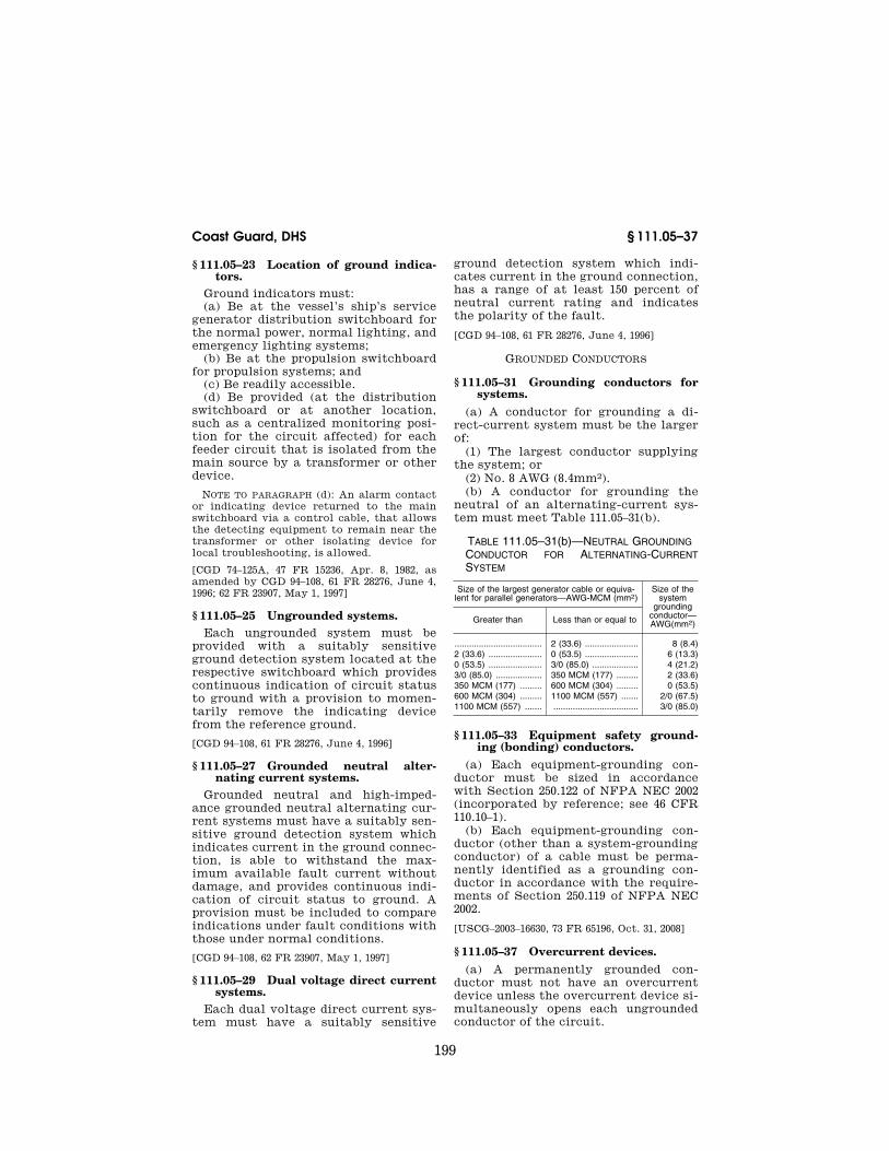
§ 111.05–31 Grounding conductors for systems.
(a) A conductor for grounding a di-rect-current system must be the larger of:
(1) The largest conductor supplying the system; or
(2) No. 8 AWG (8.4mm2). (b) A conductor for grounding the
neutral of an alternating-current sys-tem must meet Table 111.05–31(b).
TABLE 111.05–31(b)—NEUTRAL GROUNDING CONDUCTOR FOR ALTERNATING-CURRENT SYSTEM
Size of the largest generator cable or equiva-lent for parallel generators—AWG-MCM (mm2)
Size of the system
grounding conductor— AWG(mm2) Greater than Less than or equal to
.................................... 2 (33.6) ...................... 8 (8.4) 2 (33.6) ...................... 0 (53.5) ...................... 6 (13.3) 0 (53.5) ...................... 3/0 (85.0) ................... 4 (21.2) 3/0 (85.0) ................... 350 MCM (177) ......... 2 (33.6) 350 MCM (177) ......... 600 MCM (304) ......... 0 (53.5) 600 MCM (304) ......... 1100 MCM (557) ....... 2/0 (67.5) 1100 MCM (557) ....... ................................... 3/0 (85.0)
§ 111.05–33 Equipment safety ground-ing (bonding) conductors.
(a) Each equipment-grounding con-ductor must be sized in accordance with Section 250.122 of NFPA NEC 2002 (incorporated by reference; see 46 CFR 110.10–1).
(b) Each equipment-grounding con-ductor (other than a system-grounding conductor) of a cable must be perma-nently identified as a grounding con-ductor in accordance with the require-ments of Section 250.119 of NFPA NEC 2002.
[USCG–2003–16630, 73 FR 65196, Oct. 31, 2008]
§ 111.05–37 Overcurrent devices. (a) A permanently grounded con-
ductor must not have an overcurrent device unless the overcurrent device si-multaneously opens each ungrounded conductor of the circuit.
VerDate Mar<15>2010 08:26 Nov 18, 2011 Jkt 223196 PO 00000 Frm 00209 Fmt 8010 Sfmt 8010 Y:\SGML\223196.XXX 223196wre
ier-
avile
s on
DS
K3T
PT
VN
1PR
OD
with
CF
R

200
46 CFR Ch. I (10–1–11 Edition) § 111.10–1
(b) The neutral conductor of the emergency-main switchboard bus-tie must not have a switch or circuit breaker.
[CGD 94–108, 61 FR 28276, June 4, 1996]
Subpart 111.10—Power Supply § 111.10–1 Definitions.
As used in this Subpart: (a) Ships’s service loads mean elec-
trical equipment for all auxiliary serv-ices necessary for maintaining the ves-sel in a normal, operational and habit-able condition. Ship’s service loads in-clude, but are not limited to, all safety, lighting, ventilation, navigational, communications, habitability, and pro-pulsion auxiliary loads. Electrical pro-pulsion motor, bow thruster motor, cargo transfer, drilling, cargo refrig-eration for other than Class 5.2 organic peroxides and Class 4.1 self-reactive substances, and other industrial type loads are not included.
(b) Drilling loads means all loads asso-ciated exclusively with the drilling op-eration including power to the drill table, mud system, and positioning equipment.
[CGD 74–125A, 47 FR 15236, Apr. 8, 1982, as amended by CGD 94–108, 61 FR 28276, June 4, 1996; 62 FR 23907, May 1, 1997]
§ 111.10–3 Two generating sources. In addition to the emergency power
sources required under part 112 of this chapter, each self-propelled vessel and each mobile offshore drilling unit must have at least two electric generating sources.
[CGD 94–108, 61 FR 28276, June 4, 1996]
§ 111.10–4 Power requirements, gener-ating sources.
(a) The aggregate capacity of the electric ship’s service generating sources required in § 111.10–3 must be sufficient for the ship’s service loads.
(b) With the ship’s service generating source of the largest capacity stopped, the combined capacity of the remain-ing electric ship’s service generating source or sources must be sufficient to supply those services necessary to pro-vide normal operational conditions of propulsion and safety, and minimum comfortable conditions of habitability.
Habitability services include cooking, heating, air conditioning (where in-stalled), domestic refrigeration, me-chanical ventilation, sanitation, and fresh water.
(c) The capacity of the ship’s service generating sources must be sufficient for supplying the ship’s service loads without the use of a generating source which is dependent upon the speed or direction of the main propelling en-gines or shafting.
(d) Operating generators must pro-vide a continuous and uninterrupted source of power for the ship’s service load under normal operational condi-tions. Any vessel speed change or throttle movement must not cause a ship’s service load power interruption.
(e) Vessels with electric propulsion that have two or more constant-volt-age generators which supply both ship’s service and propulsion power do not need additional ship’s service gen-erators provided that with any one pro-pulsion/ship’s service generator out of service the capacity of the remaining generator(s) is sufficient for the elec-trical loads necessary to provide nor-mal operational conditions of propul-sion and safety, and minimum com-fortable conditions of habitability.
(f) A generator driven by a main pro-pulsion unit (such as a shaft generator) which is capable of providing electrical power continuously, regardless of the speed and direction of the propulsion shaft, may be considered one of the ship’s service generating sets required by § 111.10–3. A main-engine-dependent generator which is not capable of pro-viding continuous electrical power may be utilized as a supplemental generator provided that a required ship’s service generator or generators having suffi-cient capacity to supply the ship’s service loads can be automatically brought on line prior to the main-en-gine-dependent generator tripping off- line due to a change in the speed or di-rection of the main propulsion unit.
[CGD 94–108, 61 FR 28277, June 4, 1996; 61 FR 36787, July 12, 1996]
§ 111.10–5 Multiple energy sources.
Failure of any single generating set energy source such as a boiler, diesel, gas turbine, or steam turbine must not
VerDate Mar<15>2010 08:26 Nov 18, 2011 Jkt 223196 PO 00000 Frm 00210 Fmt 8010 Sfmt 8010 Y:\SGML\223196.XXX 223196wre
ier-
avile
s on
DS
K3T
PT
VN
1PR
OD
with
CF
R
201
Coast Guard, DHS § 111.12–5
cause all generating sets required in § 111.10–3 to be inoperable.
§ 111.10–7 Dead ship. (a) The generating plant of each self-
propelled vessel must provide the elec-trical services necessary to start the main propulsion plant from a dead ship condition.
(b) If the emergency generator is used for part or all of the electric power necessary to start the main pro-pulsion plant from a dead ship condi-tion, the emergency generator must be capable of providing power to all emer-gency lighting, emergency internal communications systems, and fire de-tection and alarm systems in addition to the power utilized for starting the main propulsion plant. Additional re-quirements are in § 112.05–3(c) of this chapter.
[CGD 74–125A, 47 FR 15236, Apr. 8, 1982, as amended by CGD 94–108, 61 FR 28277, June 4, 1996]
§ 111.10–9 Ship’s service supply trans-formers; two required.
If transformers are used to supply the ship’s service distribution system required by this subpart for ships and mobile offshore drilling units, there must be at least two installed, inde-pendent power transformers. With the largest transformer out of service, the capacity of the remaining units must be sufficient to supply the ship service loads.
NOTE TO § 111.10–9: A ship’s service supply system would consist of transformers, over-current protection devices, and cables, and would normally be located in the system be-tween a medium voltage bus and a low volt-age ship’s service switchboard.
[CGD 94–108, 61 FR 28277, June 4, 1996; 61 FR 33045, June 26, 1996]
Subpart 111.12—Generator Construction and Circuits
§ 111.12–1 Prime movers. (a) Prime movers must meet section
58.01–5 and 46 CFR subpart 58.10 except that those for mobile offshore drilling units must meet Part 4, Chapter 3, sec-tions 4/3.17 and 4/3.19 of the ABS MODU Rules (incorporated by reference; see 46 CFR 110.10–1). Further requirements for
emergency generator prime movers are in 46 CFR subpart 112.50.
(b) Each generator prime mover must have an overspeed device that is inde-pendent of the normal operating gov-ernor and adjusted so that the speed cannot exceed the maximum rated speed by more than 15 percent.
(c) Each prime mover must shut down automatically upon loss of lubri-cating pressure to the generator bear-ings if the generator is directly coupled to the engine. If the generator is oper-ating from a power take-off, such as a shaft driven generator on a main pro-pulsion engine, the generator must automatically declutch (disconnect) from the prime mover upon loss of lu-bricating pressure to generator bear-ings.
[CGD 94–108, 61 FR 28277, June 4, 1996; 61 FR 33045, June 26, 1996, as amended at 62 FR 23907, May 1, 1997; USCG–2003–16630, 73 FR 65196, Oct 31, 2008]
§ 111.12–3 Excitation.
In general, excitation must meet sec-tions 4–8–3/13.2(a), 4–8–5/5.5.1, 4–8–5/5.5.2, and 4–8–5/5.17.6 of the ABS Steel Vessel Rules (incorporated by reference; see 46 CFR 110.10–1), except that those for mo-bile offshore drilling units must meet Part 4, Chapter 3, sections 4/3.21.1 and 4/ 3.23.1 of the ABS MODU Rules (incor-porated by reference; see 46 CFR 110.10– 1). In particular, no static exciter may be used for excitation of an emergency generator unless it is provided with a permanent magnet or a residual-mag-netism-type exciter that has the capa-bility of voltage build-up after two months of no operation.
[USCG–2003–16630, 73 FR 65196, Oct. 31, 2008]
§ 111.12–5 Construction and testing of generators.
Each generator must meet the appli-cable requirements for construction and testing in section 4–8–3 of the ABS Steel Vessel Rules (incorporated by reference; see 46 CFR 110.10–1) except that each one for a mobile offshore drilling unit must meet the require-ments in part 4, chapter 3, section 4 of the ABS MODU Rules (incorporated by reference; see 46 CFR 110.10–1).
[USCG–2003–16630, 73 FR 65196, Oct. 31, 2008]
VerDate Mar<15>2010 08:26 Nov 18, 2011 Jkt 223196 PO 00000 Frm 00211 Fmt 8010 Sfmt 8010 Y:\SGML\223196.XXX 223196wre
ier-
avile
s on
DS
K3T
PT
VN
1PR
OD
with
CF
R

202
46 CFR Ch. I (10–1–11 Edition) § 111.12–7
§ 111.12–7 Voltage regulation and par-allel operation.
Voltage regulation and parallel oper-ation must meet:
(a) For AC systems: sections 4–2–3/ 7.5.2, 4–2–4/7.5.2, 4–8–3/3.13.2, and 4–8–3/ 3.13.3 of the ABS Steel Vessel Rules (in-corporated by reference; see 46 CFR 110.10–1);
(b) For DC systems: section 4–8–3/ 3.13.3(c) of the ABS Steel Vessel Rules, and IEC 92–202 and IEC 92–301 (both in-corporated by reference; see 46 CFR 110.10–1); and
(c) For mobile offshore drilling units: Part 4, Chapter 3, section 4/3.21.2, 4/ 3.21.3, 4/3.23.2, and 4/3.23.3 of the ABS MODU Rules (incorporated by ref-erence; see 46 CFR 110.10–1).
[USCG–2003–16630, 73 FR 65196, Oct. 31, 2008]
§ 111.12–9 Generator cables.
(a) The current-carrying capacity of generator cables must not be:
(1) Less than 115 percent of the con-tinuous generator rating; or
(2) Less than 115 percent of the over-load for a machine with a 2 hour or greater overload rating.
(b) Generator cables must not be in the bilges.
§ 111.12–11 Generator protection.
(a) Applicability. This section applies to each generator except a propulsion generator.
(b) General. Each ship’s service gener-ator and emergency generator must be protected by an individual, tripfree, air circuit breaker whose tripping charac-teristics can be set or adjusted to closely match the generator capabili-ties and meet the coordination require-ments of Subpart 111.51. Each circuit breaker must contain the trips re-quired by this section.
(c) Type of trips. A circuit breaker for a generator must:
(1) Open upon the shutting down of the prime mover;
(2) Have longtime overcurrent trips or relays set as necessary to coordinate with the trip settings of the feeder cir-cuit breakers; and
(3) Not have an instantaneous trip with the exception that an instanta-neous trip is required if:
(i) Three or more alternating-current generators can be paralleled; or
(ii) The circuit breaker is for a direct current generator.
(d) Setting of longtime overcurrent trips. The pickup setting of the longtime overcurrent trip of a generator circuit breaker must not be larger than:
(1) 115 percent of the generator rating for a continuous rated machine; or
(2) 115 percent of the overload rating for a machine with a 2-hour or greater overload rating.
(e) Setting of instantaneous trips. The instantaneous trip of a generator cir-cuit breaker must be set above, but as close as practicable to, the maximum asymmetrical short circuit available from any one of the generators that can be paralleled.
(f) Reverse-power and reverse-current trips. Each generator arranged for par-allel operation must have reverse- power or reverse-current trips.
(g) Location. A ship’s service gener-ator overcurrent protective device must be on the ship’s service generator switchboard. The generator and its switchboard must be in the same space. (For the purposes of this section, the following are not considered separate from the machinery space: (1) A con-trol room that is inside of the machin-ery casing and (2) a dedicated switch- gear and semiconductor rectifier (SCR) compartment on a mobile offshore drilling unit that is separate from but directly adjacent to and on the same level as the generator room).
(h) Three-wire, single-phase and four- wire, three-phase generators. There must be circuit breaker poles for each gener-ator lead, except in the neutral lead.
(i) Three-wire, direct-current genera-tors. Each three-wire, direct current generator must meet the following re-quirements:
(1) Circuit breaker poles. There must be separate circuit breaker poles for the positive and negative leads, and, unless the main poles provide protec-tion, for each equalizer lead. If there are equalizer poles for a three-wire generator, each overload trip must be of the ‘‘Algebraic’’ type. If there is a neutral pole in the generator circuit breaker, there must not be an overload trip element for the neutral pole. In
VerDate Mar<15>2010 08:26 Nov 18, 2011 Jkt 223196 PO 00000 Frm 00212 Fmt 8010 Sfmt 8010 Y:\SGML\223196.XXX 223196wre
ier-
avile
s on
DS
K3T
PT
VN
1PR
OD
with
CF
R

203
Coast Guard, DHS § 111.15–5
this case, there must be a neutral over-current relay and alarm system that is set to function at a current value not more than the neutral rating.
(2) Equalizer buses. For each three- wire generator, the circuit breaker must protect against a short circuit on the equalizer bus.
(j) Circuit breaker reclosing. Generator circuit breakers must not automati-cally close after tripping.
[CGD 74–125A, 47 FR 15236, Apr. 8, 1982, as amended by CGD 81–030, 53 FR 17847, May 18, 1988; CGD 94–108, 61 FR 28277, June 4, 1996; 62 FR 23908, May 1, 1997]
§ 111.12–13 Propulsion generator pro-tection.
For general requirements, see § 111.35–1 of this chapter.
Subpart 111.15—Storage Batteries and Battery Chargers: Con-struction and Installation
§ 111.15–1 General. Each battery must meet the require-
ments of this subpart.
[CGD 94–108, 61 FR 28277, June 4, 1996]
§ 111.15–2 Battery construction. (a) A battery cell, when inclined at 40
degrees from the vertical, must not spill electrolyte.
(b) Each fully charged lead-acid bat-tery must have a specific gravity that meets section 22 of IEEE 45–2002 (incor-porated by reference; see 46 CFR 110.10– 1).
(c) Batteries must not evolve hydro-gen at a rate exceeding that of a simi-lar size lead-acid battery under similar charging condition.
(d) Batteries must be constructed to take into account the environmental conditions of a marine installation, in-cluding temperature, vibration, and shock.
[CGD 94–108, 61 FR 28277, June 4, 1996, as amended by USCG–2003–16630, 73 FR 65196, Oct. 31, 2008]
§ 111.15–3 Battery categories. (a) A battery installation is classified
as one of three types, based upon power output of the battery charger, as fol-lows:
(1) Large. A large battery installation is one connected to a battery charger that has an output of more than 2 kw computed from the highest possible charging current and the rated voltage of the battery installation.
(2) Moderate. A moderate battery in-stallation is one connected to a battery charger that has an output of between 0.2 kw and 2 kw computed from the highest possible charging current and the rated voltage of the battery instal-lation.
(3) Small. A small battery installation is one connected to a battery charger that has an output of less than 0.2 kw computed from the highest possible charging current and the rated voltage of the battery installation.
(b) Batteries that generate less hy-drogen under normal charging and dis-charging conditions than an equivalent category of lead-acid batteries (e.g., sealed batteries) may have their bat-tery category reduced to an equivalent category of lead-acid batteries.
[CGD 74–125A, 47 FR 15236, Apr. 8, 1982, as amended by CGD 94–108, 61 FR 28278, June 4, 1996]
§ 111.15–5 Battery installation. (a) Large batteries. Each large battery
installation must be in a room that is only for batteries or a box on deck. In-stalled electrical equipment must meet the hazardous location requirements in subpart 111.105 of this part.
(b) Moderate batteries. Each moderate battery installation must be in a bat-tery room, in a box on deck, or in a box or locker in another space such as an engineroom, storeroom, or similar space, except if a moderate battery in-stallation is in a ventilated compart-ment such as the engineroom and is protected from falling objects, a box or locker is not required. A moderate bat-tery installation must not be in a sleeping space. An engine cranking bat-tery for one or more engines must be as close as possible to the engine or en-gines.
(c) Small batteries. Small size battery installations must not be located in poorly-ventilated spaces, such as clos-ets, or in living spaces, such as state-rooms.
(d) Battery trays. Each battery tray must be chocked with wood strips or
VerDate Mar<15>2010 08:26 Nov 18, 2011 Jkt 223196 PO 00000 Frm 00213 Fmt 8010 Sfmt 8010 Y:\SGML\223196.XXX 223196wre
ier-
avile
s on
DS
K3T
PT
VN
1PR
OD
with
CF
R
204
46 CFR Ch. I (10–1–11 Edition) § 111.15–10
their equivalent to prevent movement, and each tray must have non-absorbent insulating supports on the bottom and similar spacer blocks at the sides, or equivalent provisions for air circula-tion space all around each tray. Each battery tray must provide adequate ac-cessibility for installation, mainte-nance, and removal of the batteries.
(e) Nameplates. Each battery must be provided with the name of its manufac-turer, model number, type designation, either the cold cranking amp rating or the amp-hour rating at a specific dis-charge and, for a lead-acid battery, the fully charged specific gravity value. This information must be permanently fixed to the battery.
(f) Lining in battery rooms and lockers. (1) Each battery room and locker must have a watertight lining that is—
(i) On each shelf to a height of at least 76 mm (3 inches); or
(ii) On the deck to a height of at least 152 mm (6 inches).
(2) For lead-acid batteries, the lining must be 1.6 mm (1⁄16 inch) thick lead or other material that is corrosion-resist-ant to the electrolyte of the battery.
(3) For alkaline batteries, the lining must be 0.8 mm (1⁄32 inch) thick steel or other material that is corrosion-resist-ant to the electrolyte of the battery.
(g) Lining of battery boxes. Each bat-tery box must have a watertight lining to a height of at least 76 mm (3 inches) that meets paragraphs (f)(2) and (f)(3) of this section.
[CGD 74–125A, 47 FR 15236, Apr. 8, 1982, as amended by CGD 94–108, 61 FR 28278, June 4, 1996; 61 FR 36787, July 12, 1996; 62 FR 23908, May 1, 1997]
§ 111.15–10 Ventilation. (a) General. Each room, locker, and
box for storage batteries must be ar-ranged or ventilated to prevent accu-mulation of flammable gas.
(b) Power ventilation. If power ventila-tion is required, the following must be met:
(1) The power ventilation system must be separate from ventilation sys-tems for other spaces.
(2) Electric motors must be outside the duct and compartment and:
(i) Have an explosion-proof motor for a Class I, Division 1, Group B location; or
(ii) Be at least 10 ft. (3 m) from the exhaust end of the duct.
(3) Each blower must have a non- sparking fan.
(4) The power ventilation system must be interlocked with the battery charger so that the battery cannot be charged without ventilation.
(c) Large battery installations. Each battery room for large battery installa-tions must have a power exhaust ven-tilation system and have openings for intake air near the floor that allow the passage of the quantity of air that must be expelled. The quantity of the air expelled must be at least:
q=3.89(i)(n).
where: q=quantity of expelled air in cubic feet per hour.
i=Maximum charging current during gas for-mation, or one-fourth of the maximum ob-tainable charging current of the charging facility, whichever is greater.
n=Number of cells.
(d) Moderate and small battery installa-tions. Each battery room or battery locker for moderate or small battery installations must have louvers near the bottom of the room or locker for air, and must be ventilated by:
(1) Ventilation that meets paragraph (c) of this section;
(2) An exhaust duct: (i) That ends in a mechanically ven-
tilated space or in the weather; (ii) That extends from the top of the
room or locker to at least 3 ft. (1 m) above the top of the room or locker;
(iii) That is at an angle of 45 degrees or less from the vertical; and
(iv) That has no appliances, such as flame arresters, that impede free pas-sage of air or gas mixtures; or
(3) A duct from the top of the room or locker to an exhaust ventilation duct.
(e) Deck boxes. Except for a deck box for a small battery installation, each deck box must have a duct from the top of the box to at least 4 ft. (1.2 m) above the box ending in a gooseneck or mushroom head that prevents entrance of water. Holes for air must be on at least two parallel sides of each box.
(f) Weathertight. Each deck box must be weathertight.
(g) Boxes for small battery installations. Each box for a small battery installa-tion must have openings near the top
VerDate Mar<15>2010 08:26 Nov 18, 2011 Jkt 223196 PO 00000 Frm 00214 Fmt 8010 Sfmt 8010 Y:\SGML\223196.XXX 223196wre
ier-
avile
s on
DS
K3T
PT
VN
1PR
OD
with
CF
R

205
Coast Guard, DHS § 111.25–1
to allow escape of gas. If the installa-tion is in a non-environmentally-con-trolled location, the installation must prevent the ingress of water.
[CGD 74–125A, 47 FR 15236, Apr. 8, 1982, as amended by CGD 94–108, 61 FR 28278, June 4, 1996]
§ 111.15–20 Conductors.
(a) Each conductor penetration to a battery room must be made water-tight.
(b) The termination of each cable must be sealed to prevent the entrance of electrolyte by spray or creepage.
(c) Each connecting cable must have sufficient capacity to carry the max-imum charging current or maximum discharge current, whichever is great-er, while maintaining the proper volt-age at the load end.
[CGD 94–108, 61 FR 28278, June 4, 1996, as amended at 62 FR 23908, May 1, 1997]
§ 111.15–25 Overload and reverse cur-rent protection.
(a) An overload protective device must be in each battery conductor, ex-cept conductors of engine cranking batteries and batteries with a nominal potential of 6 volts or less. For large storage battery installations, the over-current protective devices must be next to, but outside of, the battery room.
(b) Except when a rectifier is used, the charging equipment for all bat-teries with a nominal voltage more than 20 percent of line voltage must protect automatically against reversal of current.
§ 111.15–30 Battery chargers.
Each battery charger enclosure must meet § 111.01–9. Additionally, each charger must be suitable for the size and type of battery installation that it serves. Chargers incorporating ground-ed autotransformers must not be used. Except for rectifiers, chargers with a voltage exceeding 20 percent of the line voltage must be provided with auto-matic protection against reversal of current.
[CGD 94–108, 61 FR 28278, June 4, 1996; 61 FR 36787, July 12, 1996]
Subpart 111.20—Transformer Con-struction, Installation, and Pro-tection
§ 111.20–1 General requirements.
Each transformer winding must be resistant to moisture, sea atmosphere, and oil vapor, unless special pre-cautions are taken, such as enclosing the winding in an enclosure with a high degree of ingress protection.
[CGD 94–108, 61 FR 28278, June 4, 1996]
§ 111.20–5 Temperature rise.
(a) The temperature rise, based on an ambient temperature of 40 degrees C, must not exceed the following:
(1) For Class A insulation, 55 degrees C.
(2) For Class B insulation, 80 degrees C.
(3) For Class F insulation, 115 degrees C.
(4) For Class H insulation, 150 degrees C.
(b) If the ambient temperature is higher than 40 degrees C, the trans-former must be derated so that the total temperature stated in this sec-tion is not exceeded. The temperature must be taken by the resistance meth-od.
§ 111.20–10 Autotransformers.
An autotransformer must not supply feeders or branch circuits.
§ 111.20–15 Protection of transformers against overcurrent.
Each transformer must have protec-tion against overcurrent that meets Article 450 of NFPA NEC 2002 or IEC 92–303 (both incorporated by reference; see 46 CFR 110.10–1).
[USCG–2003–16630, 73 FR 65196, Oct. 31, 2008]
Subpart 111.25—Motors
§ 111.25–1 General requirements.
The requirements for generators con-tained in § 111.12–5 apply to motors.
[CGD 74–125A, 47 FR 15236, Apr. 8, 1982, as amended by CGD 94–108, 62 FR 23908, May 1, 1997]
VerDate Mar<15>2010 08:26 Nov 18, 2011 Jkt 223196 PO 00000 Frm 00215 Fmt 8010 Sfmt 8010 Y:\SGML\223196.XXX 223196wre
ier-
avile
s on
DS
K3T
PT
VN
1PR
OD
with
CF
R

206
46 CFR Ch. I (10–1–11 Edition) § 111.25–5
§ 111.25–5 Marking.
(a) Each motor must have a marking or nameplate that meets either Section 430.7 of NFPA NEC 2002 or clause 16 of IEC 92–301 (both incorporated by ref-erence; see 46 CFR 110.10–1).
(b) The marking or nameplate for each motor that is in a corrosive loca-tion must be corrosion-resistant.
[CGD 74–125A, 47 FR 15236, Apr. 8, 1982, as amended by CGD 94–108, 61 FR 28278, June 4, 1996; USCG–2003–16630, 73 FR 65196, Oct. 31, 2008]
§ 111.25–15 Duty cycle.
Each motor must be rated for contin-uous duty, except a motor for an appli-cation listed in Table 111.25–15 or a similar duty must meet the minimum short-time rating stated in the table.
TABLE 111.25–15
Application of motor Minimum short-time rating of motor, in hours
Deck winch and direct acting capstan.
Half.
Deck winch with hydraulic transmission.
Continuous at no load fol-lowed by 1⁄2 hr. at full load.
Direct acting windlass ............ One fourth. Windlass with hydraulic trans-
mission.Half hour idle pump oper-
ation, followed by 1⁄4 hr. full load operation.
Steering gear, direct acting ... One. Steering gear, indirect drive .. Continuous operation at 15
pct. load followed by 1 hr. at full load.
Watertight door operators ...... 1⁄12. Boat winches ......................... 1⁄12.
Subpart 111.30—Switchboards
§ 111.30–1 Location and installation.
Each switchboard must meet the lo-cation and installation requirements in section 8.2 of IEEE 45–2002 or IEC 60092– 302 (both incorporated by reference; see 46 CFR 110.10–1), as applicable.
[USCG–2003–16630, 73 FR 65196, Oct. 31, 2008]
§ 111.30–3 Accessibility of switchboard components and connections.
Each component and bus bar connec-tion on a switchboard that is not acces-sible from the rear, except a bus bar connection for a draw-out type circuit breaker, must be within 0.5 m (20 in.) of the front of the switchboard.
§ 111.30–4 Circuit breakers removable from the front.
Circuit breakers, when installed on generator or distribution switchboards, must be mounted or arranged in such a manner that the circuit breaker may be removed from the front without un-bolting bus or cable connections or de-energizing the supply, unless the switchboard is divided into sections, such that each section is capable of providing power to maintain the vessel in a navigable condition, and meets § 111.30–24 (a) and (b).
[CGD 94–108, 61 FR 28278, June 4, 1996]
§ 111.30–5 Construction.
(a) All low voltage and medium volt-age switchboards (as low and medium are determined within the standard used) must meet—
(1) For low voltages, either section 8.3 of IEEE 45–2002 or IEC 60092–302 (both incorporated by reference; see 46 CFR 110.10–1), as appropriate.
(2) For medium voltages, either sec-tion 8.4 of IEEE 45–2002 or IEC 92–503 (incorporated by reference; see 46 CFR 110.10–1), as appropriate.
(b) Each switchboard must be fitted with a dripshield unless the switch-board is a deck-to-overhead mounted type which cannot be subjected to leaks or falling objects.
[CGD 94–108, 61 FR 28278, June 4, 1996, as amended at 62 FR 23908, May 1, 1997; USCG– 2003–16630, 73 FR 65196, Oct. 31, 2008]
§ 111.30–11 Deck coverings.
Non-conducting deck coverings, such as non-conducting mats or gratings, suitable for the specific switchboard voltage must be installed for personnel protection at the front and rear of the switchboard and must extend the en-tire length of, and be of sufficient width to suit, the operating space.
[CGD 94–108, 62 FR 23908, May 1, 1997]
§ 111.30–15 Nameplates.
(a) Each device must have a name-plate showing the device’s function.
(b) Each nameplate for a circuit breaker must show the electrical load served and the setting of the circuit breaker.
VerDate Mar<15>2010 08:26 Nov 18, 2011 Jkt 223196 PO 00000 Frm 00216 Fmt 8010 Sfmt 8010 Y:\SGML\223196.XXX 223196wre
ier-
avile
s on
DS
K3T
PT
VN
1PR
OD
with
CF
R

207
Coast Guard, DHS § 111.30–25
§ 111.30–17 Protection of instrument circuits.
(a) Each circuit that supplies a de-vice on a switchboard, except a circuit under paragraph (b) of this section, must have overcurrent protection.
(b) A circuit that supplies a device on a switchboard must not have overload protection if it supplies:
(1) An electric propulsion control; (2) A voltage regulator; (3) A ship’s service generator circuit
breaker tripping control; or (4) A device that creates a hazard to
the vessel if deenergized. (c) If short circuit protection is used
in any of the circuits listed in para-graph (b) of this section, it must be set at not less than 500% of the expected current.
(d) A secondary circuit of a current transformer must not be fused, and the circuit from a current transformer to a device that is not in the switchboard must have a high voltage protector to short the transformer during an open circuit.
§ 111.30–19 Buses and wiring. (a) General. Each bus must meet the
requirements of either— (1) Section 7.10 of IEEE 45–1998 (incor-
porated by reference; see 46 CFR 110.10– 1); or
(2) IEC 60092–302 (clause 7) (incor-porated by reference; see 46 CFR 110.10– 1).
(b) Wiring. Instrumentation and con-trol wiring must be—
(1) Suitable for installation within in a switchboard enclosure and be rated at 90 °C or higher;
(2) Stranded copper; (3) No. 14 AWG (2.10 mm2) or larger or
must be ribbon cable or similar con-ductor size cable recommended for use in low-power instrumentation, moni-toring, or control circuits by the equip-ment manufacturer;
(4) Flame-retardant meeting test VW–1 of UL 1581 or IEC 332–1 (both in-corporated by reference; see 46 CFR 110.10–1); and
(5) Extra flexible, if used on a hinged panel.
[CGD 94–108, 61 FR 28278, June 4, 1996, as amended at 62 FR 23908, May 1, 1997; USCG– 2003–16630, 73 FR 65197, Oct. 31, 2008]
§ 111.30–24 Generation systems greater than 3000 kw.
Except on a non-self-propelled mobile offshore drilling unit (MODU) and a non-self-propelled floating Outer Conti-nental Shelf facility, when the total in-stalled electric power of the ship’s service generation system is more than 3000 kW, the switchboard must have the following:
(a) At least two sections of the main bus that are connected by:
(1) A non-automatic circuit breaker; (2) A disconnect switch; or (3) Removable links. (b) As far as practicable, the connec-
tion of generators and duplicated equipment equalized between the sec-tions of the main bus.
[CGD 74–125A, 47 FR 15236, Apr. 8, 1982, as amended by CGD 94–108, 61 FR 28279, June 4, 1996]
§ 111.30–25 Alternating-current ship’s service switchboards.
(a) Except as allowed in paragraph (g) of this section, each alternating-cur-rent ship’s service switchboard must have the equipment required by para-graphs (b) through (f) of this section.
(b) For each connected generator, each switchboard must have the fol-lowing:
(1) A circuit breaker that meets § 111.12–11 and § 111.50–5.
(2) A disconnect switch or link for each generator conductor, except a switchboard having a draw-out or plug- in type generator circuit breaker that disconnects:
(i) Each generator conductor; or (ii) If there is a switch in the gener-
ator neutral, each ungrounded con-ductor.
(3) A pilot lamp connected between the generator and the circuit breaker.
(4) An ammeter with a selector switch that connects the ammeter to show the current in each phase.
(5) A voltmeter with a selector switch that connects the voltmeter to show the:
(i) Generator voltage of each phase; and
(ii) Bus voltage of one phase. (6) A voltage regulator and voltage
regulator functional cut-out switch. (c) For each generator that is not ex-
cited from a variable voltage or rotary
VerDate Mar<15>2010 08:26 Nov 18, 2011 Jkt 223196 PO 00000 Frm 00217 Fmt 8010 Sfmt 8010 Y:\SGML\223196.XXX 223196wre
ier-
avile
s on
DS
K3T
PT
VN
1PR
OD
with
CF
R
208
46 CFR Ch. I (10–1–11 Edition) § 111.30–27
amplifier that is controlled by a volt-age regulator unit acting on the ex-citer field, each switchboard must have:
(1) A generator field rheostat; (2) A double-pole field switch; (3) Discharge clips; and (4) A discharge resistor. (d) If generators are arranged for par-
allel operation, each switchboard must have:
(1) A speed control for the prime mover of each generator;
(2) An indicating wattmeter for each generator; and
(3) A synchroscope and synchronizing lamp that have a selector switch to show synchronization for paralleling generators.
(e) Each switchboard must have the following:
(1) Ground detection that meets Sub-part 111.05 for the:
(i) Ship’s service power system; (ii) Normal lighting system; and (iii) Emergency lighting system. (2) A frequency meter with a selector
switch to connect the meter to each generator.
(3) An exciter field rheostat. (f) For each shore power connection
each switchboard must have: (1) A circuit breaker or fused switch; (2) A pilot light connected to the
shore side of the circuit breaker or fused switch; and
(3) One of the voltmeters under para-graph (b)(5) of this section connected to show the voltage of each phase of the shore power connection.
(g) The equipment under paragraphs (b), (d), (e), and (f) of this section, ex-cept the equipment under paragraphs (b)(1), (b)(2), and (f)(1), must be on the ship’s service switchboard or on a cen-tral control console that:
(1) Is in the same control area as the main ship’s service switchboard or can remotely control the ship’s service gen-erator circuit breaker;
(2) Has a generator section that has only generator functions;
(3) Has the generator section seg-regated from each other console sec-tion by a fire-resistant barrier; and
(4) Has cabling from the main switch-board to the generator section of the console that:
(i) Has only generator control and generator instrumentation circuits; and
(ii) Is protected from mechanical damage.
§ 111.30–27 Direct current ship’s serv-ice switchboards.
(a) Each direct current ship’s service switchboard must have the equipment required by paragraphs (b) through (f) of this section.
(b) For each connected generator, each switchboard must have the fol-lowing:
(1) A circuit breaker that meets § 111.12–11 and § 111.50–5.
(2) A disconnect switch or link for each generator conductor, except a switchboard having a draw-out or plug- in type generator circuit breaker that disconnects—
(i) Each conductor; or (ii) If there is a switch in the gener-
ator neutral, each ungrounded con-ductor.
(3) A field rheostat. (4) A pilot lamp connected between
the generator and circuit breaker. (c) For each two-wire generator, each
switchboard must have: (1) An ammeter; and (2) A voltmeter with a selector
switch that connects the voltmeter to show:
(i) Generator voltage; and (ii) Bus voltage. (d) For each three-wire generator,
each switchboard must have the fol-lowing:
(1) An ammeter for: (i) The positive lead; and (ii) The negative lead. (2) A center zero type ammeter for
the neutral ground connection. (3) A voltmeter with a selector
switch that connects the voltmeter to show generator and bus voltage:
(i) Positive to negative; (ii) Positive to neutral; and (iii) Neutral to negative. (e) Each switchboard must have
ground detection that meets Subpart 111.05 for the:
(1) Main power system; (2) Main lighting system; and (3) Emergency lighting system. (f) For each shore power connection,
each switchboard must have:
VerDate Mar<15>2010 08:26 Nov 18, 2011 Jkt 223196 PO 00000 Frm 00218 Fmt 8010 Sfmt 8010 Y:\SGML\223196.XXX 223196wre
ier-
avile
s on
DS
K3T
PT
VN
1PR
OD
with
CF
R

209
Coast Guard, DHS § 111.33–3
(1) A circuit breaker or fused switch; and
(2) A pilot light connected to the shore side.
(g) One of the voltmeters under para-graph (c)(2) or (d)(3) of this section must be connected to show:
(1) For each two-wire system, shore connection voltage; and
(2) For each three-wire system, shore connection voltage:
(i) Positive to negative; (ii) Positive to neutral; and (iii) Neutral to negative.
§ 111.30–29 Emergency switchboards. (a) Each emergency generator must
have an emergency switchboard. (b) There must be a test switch at the
emergency switchboard to simulate a failure of the normal power source and cause the emergency loads to be sup-plied from the emergency power source.
(c) The emergency switchboard must be as near as practicable to the emer-gency power source but not in the same space as a battery emergency power source.
(d) Each alternating-current emer-gency switchboard must have the equipment required by paragraphs (c) through (e) of this section.
(e) For each connected emergency generator, each emergency switchboard must have:
(1) A circuit breaker that meets § 111.12–11;
(2) A disconnect switch or link for each emergency generator conductor, except for a switchboard with a draw out or plug-in type generator circuit breaker that disconnects:
(i) Each generator conductor; and (ii) If there is a switch in the gener-
ator neutral, each ungrounded con-ductor; and
(3) A pilot lamp connected between the generator and circuit breaker.
(f) For each emergency generator that is not excited from a variable voltage or rotary amplifier exciter that is controlled by a voltage regulator unit acting on the exciter field, each emergency switchboard must have:
(1) A generator field rheostat; (2) A double pole field switch; (3) Discharge clips; and (4) A discharge resistor.
(g) Each emergency switchboard must have the following:
(1) An ammeter with a selector switch that connects the ammeter to show the current for each phase.
(2) A voltmeter with a selector switch that connects the voltmeter to show:
(i) Generator voltage of each phase; and
(ii) Bus voltage of one phase. (3) Ground detection that meets sub-
part 111.05 for the emergency lighting system.
(4) A frequency meter. (5) An exciter field rheostat. (6) A voltage regulator and a voltage
regulator functional cut-out switch. (h) Each direct-current emergency
switchboard must have the: (1) Equipment under § 111.30–27 (b)
through (d); and (2) Ground detection under subpart
111.05 for the emergency lighting sys-tem.
[CGD 74–125A, 47 FR 15236, Apr. 8, 1982, as amended by CGD 94–108, 61 FR 28279, June 4, 1996]
Subpart 111.33—Power Semiconductor Rectifier Systems
§ 111.33–1 General. This subpart is applicable to all
power semiconductor rectifier systems. In addition to the regulations con-tained in this subpart, the require-ments of §§ 111.30–11, 111.30–19 and 111.30–21 of this part must be met, if ap-plicable.
§ 111.33–3 Nameplate data. (a) Each semiconductor rectifier sys-
tem must have a nameplate of durable material affixed to the unit that meets the requirements of—
(1) Section 10.20.12 of IEEE 45–2002 (incorporated by reference; see 46 CFR 110.10–1); or
(2) Clause 8 of IEC 92–304 (incor-porated by reference; see 46 CFR 110.10– 1).
(b) Each semiconductor rectifier sys-tem must have a nameplate containing the words ‘‘marine semiconductor rec-tifier,’’ and the following information:
(1) Manufacturer’s name and address. (2) Manufacturer’s serial number. (3) Type.
VerDate Mar<15>2010 08:26 Nov 18, 2011 Jkt 223196 PO 00000 Frm 00219 Fmt 8010 Sfmt 8010 Y:\SGML\223196.XXX 223196wre
ier-
avile
s on
DS
K3T
PT
VN
1PR
OD
with
CF
R

210
46 CFR Ch. I (10–1–11 Edition) § 111.33–5
(4) Rated AC volts. (5) Rated AC amperes. (6) Number of phases. (7) Frequency. (8) Rated DC volts. (9) Rated DC amperes. (10) Ambient temperature range. (11) Duty cycle. (12) Cooling medium. (c) If, on small rectifiers, the infor-
mation required by paragraph (a) of this section cannot be shown because of space limitations, the nameplate must be at least large enough to con-tain the manufacturer’s name and se-rial number. The remaining informa-tion must be shown on the schematic diagram.
[CGD 74–125A, 47 FR 15236, Apr. 8, 1982, as amended by CGD 94–108, 61 FR 28279, June 4, 1996; USCG–2003–16630, 73 FR 65197, Oct. 31, 2008]
§ 111.33–5 Installation. Each semiconductor rectifier system
must meet the installation require-ments, as appropriate, of—
(a) Sections 10.20.2, 10.20.7, and 10.20.8 of IEEE 45–2002 (incorporated by ref-erence; see 46 CFR 110.10–1); or
(b) IEC 92–304 (incorporated by ref-erence; see 46 CFR 110.10–1).
[CGD 94–108, 61 FR 28279, June 4, 1996, as amended by USCG–2003–16630, 73 FR 65197, Oct. 31, 2008]
§ 111.33–7 Alarms and shutdowns. Each power semiconductor rectifier
must have a high temperature alarm or shutdown, except as provided in § 111.33–11.
§ 111.33–9 Ventilation exhaust. The exhaust of each forced-air semi-
conductor rectifier system must: (a) Terminate in a location other
than a hazardous location under Sub-part 111.105 of this part; and
(b) Not impinge upon any other elec-tric device.
§ 111.33–11 Propulsion systems. Each power semiconductor rectifier
system in a propulsion system must meet sections 4–8–5/5.17.9 and 4–8–5/ 5.17.10 of ABS Steel Vessel Rules (in-corporated by reference; see 46 CFR 110.10–1), except that each one for mo-bile offshore drilling units must meet
the requirements in Part 4, Chapter 3, section 4/3.5.3 of ABS MODU Rules (in-corporated by reference; see 46 CFR 110.10–1).
[USCG–2003–16630, 73 FR 65197, Oct. 31, 2008]
Subpart 111.35—Electric Propulsion
§ 111.35–1 Electrical propulsion instal-lations.
Each electric propulsion installation must meet sections 4–8–5/5.5, 4–8–5/5.11, 4–8–5/5.13, 4–8–5/5.17.8(e), 4–8–5/5.17.9, and 4–8–5/5.17.10 of ABS Steel Vessel Rules (incorporated by reference; see 46 CFR 110.10–1), except that each one for mo-bile offshore drilling units must meet the requirements in part 4, chapter 3, section 4/3.5.3 of ABS MODU Rules (in-corporated by reference; see 46 CFR 110.10–1).
[USCG–2003–16630, 73 FR 65197, Oct. 31, 2008]
Subpart 111.40—Panelboards
§ 111.40–1 Panelboard standard.
Each panelboard must meet section 17.1 of IEEE 45–2002 (incorporated by reference; see 46 CFR 110.10–1).
[USCG–2003–16630, 73 FR 65197, Oct. 31, 2008]
§ 111.40–5 Enclosure. Each panelboard must have a non-
combustible enclosure that meets §§ 111.01–7 and 111.01–9.
[CGD 94–108, 61 FR 28279, June 4, 1996]
§ 111.40–7 Location. Each panelboard must be accessible
but not in a bunker or a cargo hold, ex-cept a cargo hold on a roll-on/roll-off vessel.
[CGD 94–108, 61 FR 28279, June 4, 1996]
§ 111.40–9 Locking device. The door of each panelboard enclo-
sure that is accessible to any passenger must have a locking device.
§ 111.40–11 Numbered switching unit and panelboard directory.
(a) Each panelboard switching unit must be numbered.
(b) Each panelboard must have:
VerDate Mar<15>2010 08:26 Nov 18, 2011 Jkt 223196 PO 00000 Frm 00220 Fmt 8010 Sfmt 8010 Y:\SGML\223196.XXX 223196wre
ier-
avile
s on
DS
K3T
PT
VN
1PR
OD
with
CF
R

211
Coast Guard, DHS § 111.50–3
(1) A circuit directory cardholder; and
(2) A circuit directory that has: (i) The circuit designation of each
circuit; (ii) A description of the load of each
circuit; and (iii) The rating or setting of the over-
current protective device for each cir-cuit.
§ 111.40–13 Rating. Each panelboard must have a current
rating not less than the feeder circuit capacity.
§ 111.40–15 Overcurrent device. The total load on any overcurrent de-
vice located in a panelboard must not exceed 80 percent of its rating if, in normal operation, the load will con-tinue for 3 hours or more; except if the assembly, including the overcurrent device, is rated for continuous duty at 100% of its rating.
Subpart 111.50—Overcurrent Protection
§ 111.50–1 Protection of equipment. Overcurrent protection of electric
equipment must meet the following listed subparts of this chapter:
(a) Appliances, Subpart 111.77. (b) Generators, Subpart 111.12. (c) Motors, motor circuits, and con-
trollers, Subpart 111.70. (d) Transformers, Subpart 111.20.
§ 111.50–2 Systems integration. The electrical characteristics of each
overcurrent protective device must be compatible with other devices and its coordination must be considered in the design of the entire protective system.
NOTE TO § 111.50–2: The electrical character-istics of overcurrent protective devices may differ between standards. The interchange-ability and compatibility of components complying with differing standards cannot be assumed.
[CGD 94–108, 61 FR 28279, June 4, 1996]
§ 111.50–3 Protection of conductors. (a) Purpose. The purpose of overcur-
rent protection for conductors is to open the electric circuit if the current reaches a value that will cause an ex-
cessive or dangerous temperature in the conductor or conductor insulation. A grounded conductor is protected from overcurrent if a protective device of a suitable rating or setting is in each ungrounded conductor of the same circuit.
(b) Overcurrent protection of conduc-tors. Each conductor must be protected in accordance with its current carrying capacity, except a conductor for the following circuits which must meet the following listed subparts of this chap-ter:
(1) Propulsion circuits, Subpart 111.35.
(2) Steering circuits, subchapter F of this chapter.
(3) Motor circuits, Subpart 111.70. (4) Flexible cord and fixture wire for
lighting circuits, Subpart 111.75. (5) Switchboard circuits, Subpart
111.30. (c) Fuses and circuitbreakers. If the al-
lowable current-carrying capacity of the conductor does not correspond to a standard rating for fuses or circuitbreakers that meets Section 240.6 of NFPA NEC 2002 or IEC 92–202 (both incorporated by reference; see 46 CFR 110.10–1), then the next larger such rating is acceptable, except that:
(1) This rating must not be larger than 150 percent of the current-car-rying capacity of the conductor; and
(2) The effect of temperature on the operation of fuses and thermally con-trolled circuitbreakers must be taken into consideration.
(d) Parallel overcurrent protective de-vices. An overcurrent protective device must not be connected in parallel with another overcurrent protective device.
(e) Thermal devices. No thermal cut-out, thermal relay, or other device not designed to open a short circuit may be used for protection of a conductor against overcurrent due to a short cir-cuit or ground, except in a motor cir-cuit as described in Article 430 of NFPA NEC 2002 or in IEC 92–202.
(f) Ungrounded conductors. A fuse or overcurrent trip unit of a circuit breaker must be in each ungrounded conductor. A branch switch or circuit breaker must open all conductors of the circuit, except grounded conduc-tors.
VerDate Mar<15>2010 08:26 Nov 18, 2011 Jkt 223196 PO 00000 Frm 00221 Fmt 8010 Sfmt 8010 Y:\SGML\223196.XXX 223196wre
ier-
avile
s on
DS
K3T
PT
VN
1PR
OD
with
CF
R

212
46 CFR Ch. I (10–1–11 Edition) § 111.50–5
(g) Grounded conductor. An overcur-rent device must not be in a perma-nently grounded conductor, except:
(1) An overcurrent device that simul-taneously opens all conductors of the circuit, unless prohibited by § 111.05–17 for the bus-tie feeder connecting the emergency and main switchboards; and
(2) For motor-running protection de-scribed in Article 430 of NFPA NEC 2002 or in IEC 92–202.
[CGD 74–125A, 47 FR 15236, Apr. 8, 1982, as amended by CGD 94–108, 61 FR 28279, June 4, 1996; CGD 97–057, 62 FR 51047, Sept. 30, 1997; USCG–2003–16630, 73 FR 65197, Oct. 31, 2008]
§ 111.50–5 Location of overcurrent pro-tective devices.
(a) Location in circuit. Overcurrent de-vices must be at the point where the conductor to be protected receives its supply, except as follows:
(1) The generator overcurrent protec-tive device must be on the ship’s serv-ice generator switchboard. (See § 111.12– 11(g) for additional requirements.)
(2) The overcurrent protection for the shore connection conductors must meet § 111.30–25.
(3) If the overcurrent device that pro-tects the larger conductors also pro-tects the smaller conductors, an over-current device is not required at the supply to the smaller conductors.
(4) If the overcurrent device pro-tecting the primary side of a single phase transformer (two wire with sin-gle-voltage secondary) also protects the conductors connected to the sec-ondary side, as determined by multi-plying the current-carrying capacity of the secondary conductor by the sec-ondary to primary transformer voltage ratio, and this protection meets § 111.20–15 of this chapter, an overcur-rent device is not required at the sup-ply to the secondary side conductors.
(b) Location on vessel. Each overcur-rent device:
(1) Must be: (i) Readily accessible; and (ii) In a distribution panelboard,
switchboard, motor controller, or simi-lar enclosure; and
(2) Must not be: (i) Exposed to mechanical damage;
and
(ii) Near an easily ignitable material or where explosive gas or vapor may accumulate.
§ 111.50–7 Enclosures. (a) Each enclosure of an overcurrent
protective device must meet Sections 240–30 and 240–33 of NFPA NEC 2002 (in-corporated by reference; see 46 CFR 110.10–1).
(b) No enclosure may be exposed to the weather unless accepted by the Commandant.
[CGD 74–125A, 47 FR 15236, Apr. 8, 1982, as amended by USCG–2003–16630, 73 FR 65197, Oct. 31, 2008]
§ 111.50–9 Disconnecting and guard-ing.
Disconnecting and guarding of over-current protective devices must meet Part IV of Article 240 of NFPA NEC 2002 (incorporated by reference; see 46 CFR 110.10–1).
[USCG–2003–16630, 73 FR 65197, Oct. 31, 2008]
Subpart 111.51—Coordination of Overcurrent Protective Devices
§ 111.51–1 Purpose. The purpose of this subpart is to pro-
vide continuity of service for equip-ment vital to the propulsion, control or safety of the vessel under short-circuit conditions through coordination and selective operation of overcurrent pro-tective devices.
§ 111.51–3 Protection of vital equip-ment.
(a) The coordination of overcurrent protective devices must be dem-onstrated for all potential plant con-figurations.
(b)Overcurrent protective devices must be installed so that:
(1) A short-circuit on a circuit that is not vital to the propulsion, control, or safety of the vessel does not trip equip-ment that is vital; and
(2) A short-circuit on a circuit that is vital to the propulsion, control, or safety of the vessel is cleared only by the protective device that is closest to the point of the short-circuit.
[CGD 74–125A, 47 FR 15236, Apr. 8, 1982, as amended by CGD 94–108, 62 FR 23908, May 1, 1997]
VerDate Mar<15>2010 08:26 Nov 18, 2011 Jkt 223196 PO 00000 Frm 00222 Fmt 8010 Sfmt 8010 Y:\SGML\223196.XXX 223196wre
ier-
avile
s on
DS
K3T
PT
VN
1PR
OD
with
CF
R

213
Coast Guard, DHS § 111.54–1
Subpart 111.52—Calculation of Short-Circuit Currents
§ 111.52–1 General.
The available short-circuit current must be computed—
(a) From the aggregate contribution of all generators that can simulta-neously operate in parallel;
(b) From the largest probable motor load; and
(c) With a three phase fault on the load terminals of the protective device.
[CGD 74–125A, 47 FR 15236, Apr. 8, 1982, as amended by CGD 94–108, 61 FR 28279, June 4, 1996]
§ 111.52–3 Systems below 1500 kilo-watts.
The following short-circuit assump-tions must be made for a system with an aggregate generating capacity below 1500 kilowatts, unless detailed computations in accordance with § 111.52–5 are submitted:
(a) The maximum short-circuit cur-rent of a direct current system must be assumed to be 10 times the aggregate normal rated generator currents plus six times the aggregate normal rated currents of all motors that may be in operation.
(b) The maximum asymmetrical short-circuit current for an alternating current system must be assumed to be 10 times the aggregate normal rated generator currents plus four times the aggregate normal rated currents of all motors that may be in operation.
(c) The average asymmetrical short- circuit current for an alternating-cur-rent system must be assumed to be 81⁄2 times the aggregate normal rated gen-erator currents plus 31⁄2 times the ag-gregate normal rated currents of all motors that may be in operation.
§ 111.52–5 Systems 1500 kilowatts or above.
Short-circuit calculations must be submitted for systems with an aggre-gate generating capacity of 1500 kilo-watts or more by utilizing one of the following methods:
(a) Exact calculations using actual impedance and reactance values of sys-tem components.
(b) Estimated calculations using NAVSEA DDS 300–2 (incorporated by reference, see 46 CFR 110.10–1).
(c) Estimated calculations using IEC 61363–1 (incorporated by reference; see 46 CFR 110.10–1).
(d) The estimated calculations using a commercially established analysis procedure for utility or industrial ap-plications.
[CGD 94–108, 61 FR 28279, June 4, 1996, as amended by USCG–2003–16630, 73 FR 65197, Oct. 31, 2008]
Subpart 111.53—Fuses § 111.53–1 General.
(a) Each fuse must— (1) Meet the general provisions of Ar-
ticle 240 of NFPA NEC 2002 or IEC 92– 202 (both incorporated by reference; see 46 CFR 110.10–1) as appropriate.
(2) Have an interrupting rating suffi-cient to interrupt the asymmetrical RMS short-circuit current at the point of application; and
(3) Be listed by an independent lab-oratory.
(b) Renewable link cartridge-type fuses must not be used.
(c) Each fuse installation must pro-vide for ready access to test the condi-tion of the fuse.
[CGD 94–108, 61 FR 28279, June 4, 1996, as amended by61 FR 33045, June 26, 1996; USCG– 2003–16630, 73 FR 65197, Oct. 31, 2008]
Subpart 111.54—Circuit Breakers
§ 111.54–1 Circuit breakers. (a) Each Circuit breaker must— (1) Meet the general provision of Ar-
ticle 240 of NFPA NEC 2002 or IEC 92– 202 (both incorporated by reference; see 46 CFR 110.10–1) as appropriate;
(2) Meet subpart 111.55 of this part; and
(3) Have an interrupting rating suffi-cient to interrupt the maximum asym-metrical short-circuit current avail-able at the point of application.
(b) No molded-case circuitbreaker may be used in any circuit having a nominal voltage of more than 600 volts (1,000 volts for a circuit containing a circuitbreaker manufactured to the standards of the IEC). Each molded- case circuitbreaker must meet section
VerDate Mar<15>2010 08:26 Nov 18, 2011 Jkt 223196 PO 00000 Frm 00223 Fmt 8010 Sfmt 8010 Y:\SGML\223196.XXX 223196wre
ier-
avile
s on
DS
K3T
PT
VN
1PR
OD
with
CF
R

214
46 CFR Ch. I (10–1–11 Edition) § 111.54–3
9 and marine supplement SA of UL 489 (incorporated by reference, see 46 CFR 110.10–1) or part 2 of IEC 60947–2 (incor-porated by reference; see § 110.10–1), ex-cept as noted in paragraph (e) of this section.
(c) Each circuitbreaker, other than a molded-case one, that is for use in any of the following systems must meet the following requirements:
(1) An alternating-current system having a nominal voltage of 600 volts or less (1,000 volts for such a system with circuitbreakers manufactured to the standards of the IEC) must meet:
(i) IEEE C37.13 (incorporated by ref-erence; see 46 CFR 110.10–1);
(ii) ANSI/IEEE C37.27 (incorporated by reference; see 46 CFR 110.10–1); or
(iii) IEC 60947–2. (2) A direct-current system of 3,000
volts or less must meet IEEE C37.14 (incorporated by reference; see 46 CFR 110.10–1) or IEC 60947–2.
(3) An alternating-current system having a nominal voltage greater than 600 volts (or greater than 1,000 volts for IEC standard circuitbreakers) must meet:
(i) IEEE C37.04, IEEE C37.010, and ANSI/IEEE C37.12 (all three standards incorporated by reference; see 46 CFR 110.10–1); or
(ii) IEC 62271–100 (incorporated by ref-erence; see 46 CFR 110.10–1).
(d) A circuit breaker must not: (1) Be dependent upon mechanical
cooling to operate within its rating; or (2) Have a long-time-delay trip ele-
ment set above the continuous current rating of the trip element or of the cir-cuit breaker frame.
(e) Each circuit breaker located in an engineroom, boilerroom, or machinery space must be calibrated for a 50 degree C ambient temperature. If the circuit breaker is located in an environ-mentally controlled machinery control room where provisions are made for en-suring an ambient temperature of 40 degree C or less, a circuit breaker must have at least the standard 40 degrees C ambient temperature calibration.
[CGD 74–125A, 47 FR 15236, Apr. 8, 1982, as amended by CGD 94–108, 61 FR 28279, June 4, 1996; 61 FR 33045, June 26, 1996; 62 FR 23908, May 1, 1997; USCG–2003–16630, 73 FR 65197, Oct. 31, 2008]
§ 111.54–3 Remote control.
Remotely controlled circuit breakers must have local manual means of oper-ation.
[CGD 81–030, 53 FR 17847, May 18, 1988]
Subpart 111.55—Switches
§ 111.55–1 General.
(a) Each switch must meet Article 404 of NFPA NEC 2002 (incorporated by reference; see 46 CFR 110.10–1).
(b) Each switch that is in the weath-er must be in a watertight enclosure and be externally operable.
[CGD 74–125A, 47 FR 15236, Apr. 8, 1982, as amended by USCG–2003–16630, 73 FR 65198, Oct. 31, 2008]
§ 111.55–3 Circuit connections.
The load side of each circuit must be connected to the fuse end of a fused- switch or to the coil end of a circuit breaker, except a generator which is connected to either end of a circuit breaker.
Subpart 111.59—Busways
§ 111.59–1 General.
Each busway must meet Article 368 of NFPA NEC 2002 (incorporated by ref-erence; see 46 CFR 110.10–1).
[USCG–2003–16630, 73 FR 65198, Oct. 31, 2008]
§ 111.59–3 No mechanical cooling. A busway must not need mechanical
cooling to operate within its rating.
[CGD 94–108, 61 FR 28280, June 4, 1996]
Subpart 111.60—Wiring Materials and Methods
§ 111.60–1 Construction and testing of cable.
(a) Each marine shipboard cable must meet all the requirements for construc-tion and identification of either IEEE 1580, UL 1309, IEC 92–353, or NPFC MIL– C–24640A or NPFC MIL–C–24643A (all five standards incorporated by ref-erence; see 46 CFR 110.10–1), including the respective flammability tests con-tained therein, and must be of a cop-per-stranded type.
VerDate Mar<15>2010 08:26 Nov 18, 2011 Jkt 223196 PO 00000 Frm 00224 Fmt 8010 Sfmt 8010 Y:\SGML\223196.XXX 223196wre
ier-
avile
s on
DS
K3T
PT
VN
1PR
OD
with
CF
R

215
Coast Guard, DHS § 111.60–5
(b) Each cable constructed to IEC 92– 353 must meet the flammability re-quirements of Category A of IEC 60332– 3–22 (incorporated by reference; see 46 CFR 110.10–1).
(c) Medium-voltage electric cable must meet the requirements of IEEE 1580 and UL 1072 (incorporated by ref-erence; see 46 CFR 110.10–1), where ap-plicable, for cables rated above 5,000 volts.
(d) Electrical cable that has a poly-vinyl-chloride insulation with a nylon jacket (Type T/N) must meet either UL 1309, IEEE 1580, or section 8 of IEEE 45– 2002 (incorporated by reference; see 46 CFR 110.10–1).
(e) Electrical cable regardless of con-struction must meet, at a minimum, all of the performance and marking re-quirements of section 5.13 of IEEE 1580.
[USCG–2003–16630, 73 FR 65198, Oct. 31, 2008]
§ 111.60–2 Specialty cable for commu-nication and RF applications.
Specialty cable such as certain co-axial cable that cannot pass the flam-mability test contained in IEEE 1580, test VW–1 of UL 1581, or Category A of IEC 60332–3–22 (all three standards in-corporated by reference; see 46 CFR 110.10–1) because of unique properties of construction, must:
(a) Be installed physically separate from all other cable; and
(b) Have fire stops installed— (1) At least every 7 meters (21.5 feet)
vertically, up to a maximum of 2 deck heights;
(2) At least every 15 meters (46 feet) horizontally;
(3) At each penetration of an A or B Class boundary;
(4) At each location where the cable enters equipment; or
(5) In a cableway that has an A–60 fire rating.
[CGD 94–108, 61 FR 28280, June 4, 1996, as amended by USCG–2003–16630, 73 FR 65198, Oct. 31, 2008]
§ 111.60–3 Cable application. (a)(1) Cable constructed according to
IEEE 1580 must meet the provisions for cable application of section 24 of IEEE 45–2002 (both incorporated by reference; see 46 CFR 110.10–1).
(2) Cable constructed according to IEC 92–353 or UL 1309 (both incor-
porated by reference; see 46 CFR 110.10– 1) must meet section 24 of IEEE 45–2002, except 24.6.1, 24.6.7, and 24.8.
(3) Cable constructed according to IEC 92–353 must be applied in accord-ance with IEC 60092–352 (incorporated by reference; see 46 CFR 110.10–1), Table 1, for ampacity values.
(b)(1) Cable constructed according to IEEE 1580 must be applied in accord-ance with Table 25, Note 6, of IEEE 45– 2002.
(2) Cable constructed according to IEC 92–353 must be derated according to IEC 60092–352, clause 8.
(3) Cable constructed according to NPFC MIL–C–24640A or NPFC MIL–C– 24643A must be derated according to NAVSEA MIL–HDBK–299 (SH) (all three standards incorporated by ref-erence; see 46 CFR 110.10–1).
(c) Cable for special applications de-fined in section 24 of IEEE 45–2002 must meet the provisions of that section.
[USCG–2003–16630, 73 FR 65198, Oct. 31, 2008]
§ 111.60–4 Minimum cable conductor size.
Each cable conductor must be #18 AWG (0.82 mm2) or larger except—
(a) Each power and lighting cable conductor must be #14 AWG (2.10 mm2) or larger; and
(b) Each thermocouple, pyrometer, or instrumentation cable conductor must be #22 AWG (0.33 mm2) or larger.
[CGD 94–108, 61 FR 28280, June 4, 1996]
§ 111.60–5 Cable installation.
(a) Each cable installation must meet—
(1) Sections 25, except 25.11, of IEEE 45–2002 (incorporated by reference; see 46 CFR 110.10–1); or
(2) Cables manufactured to IEC 92–353 must be installed in accordance with IEC 60092–352 (both incorporated by ref-erence; see 46 CFR 110.10–1), including clause 8.
(b) Each cable installation made in accordance with clause 8 of IEC 60092– 352 must utilize the conductor ampacity values of Table I of IEC 60092–352.
(c) No cable may be located in any tank unless—
VerDate Mar<15>2010 08:26 Nov 18, 2011 Jkt 223196 PO 00000 Frm 00225 Fmt 8010 Sfmt 8010 Y:\SGML\223196.XXX 223196wre
ier-
avile
s on
DS
K3T
PT
VN
1PR
OD
with
CF
R

216
46 CFR Ch. I (10–1–11 Edition) § 111.60–6
(1) The purpose of the cable is to sup-ply equipment or instruments espe-cially designed for and compatible with service in the tank and whose function requires the installation of the cable in the tank;
(2) The cable is either compatible with the liquid or gas in the tank or protected by an enclosure; and
(3) Neither braided cable armor nor cable metallic sheath is used as the grounding conductor.
(d) Braided cable armor or cable me-tallic sheath must not be used as the grounding conductor.
[CGD 74–125A, 47 FR 15236, Apr. 8, 1982, as amended by CGD 94–108, 61 FR 28280, June 4, 1996; USCG–2003–16630, 73 FR 65198, Oct. 31, 2008]
§ 111.60–6 Fiber optic cable.
Each fiber optic cable must— (a) Be constructed to pass the flam-
mability test contained in IEEE 1202, test VW–1 of UL 1581, or Category A of IEC 60332–3–22 (all three standards in-corporated by reference; see 46 CFR 110.10–1); or
(b) Be installed in accordance with § 111.60–2.
[CGD 94–108, 61 FR 28280, June 4, 1996, as amended by USCG–2003–16630, 73 FR 65198, Oct. 31, 2008]
§ 111.60–7 Demand loads. Generator, feeder, and bus-tie cables must be selected on the basis of a com-
puted load of not less than the demand load given in Table 111.60–7.
TABLE 111.60–7—DEMAND LOADS
Type of circuit Demand load
Generator cables ......................................................... 115 percent of continuous generator rating. Switchboard bus-tie, except ship’s service to emer-
gency switchboard bus-tie.75 percent of generating capacity of the larger switchboard.
Emergency switchboard bus-tie ................................... 115 percent of continuous rating of emergency generator. Motor feeders ............................................................... Article 430, NFPA NEC 2002 (incorporated by reference; see 46 CFR
110.10–1). Galley equipment feeder .............................................. 100 percent of either the first 50 KW or one-half the connected load,
whichever is the larger, plus 65 percent of the remaining connected load, plus 50 percent of the rating of the spare switches or circuit breakers on the distribution panel.
Lighting feeder ............................................................. 100 percent of the connected load plus the average active circuit load for the spare switches or circuit breakers on the distribution panels.
Grounded neutral of a dual voltage feeder ................. 100 percent of the capacity of the ungrounded conductors when ground-ed neutral is not protected by a circuit breaker overcurrent trip, or not less than 50 percent of the capacity of the ungrounded conductors when the grounded neutral is protected by a circuit breaker overcur-rent trip or overcurrent alarm.
[CGD 74–125A, 47 FR 15236, Apr. 8, 1982, as amended by USCG–2004–18884, 69 FR 58348, Sept. 30, 2004; USCG–2003–16630, 73 FR 65198, Oct. 31, 2008]
§ 111.60–9 Segregation of vital circuits.
(a) General. A branch circuit that supplies equipment vital to the propul-sion, control, or safety of the vessel must not supply any other equipment.
(b) Passenger vessels. (1) Each pas-senger vessel with firescreen bulkheads that form main fire zones must have distribution systems arranged so that fire in a main fire zone does not inter-
fere with essential services in another main fire zone.
(2) Main and emergency feeders pass-ing through a main fire zone must be separated vertically and horizontally as much as practicable.
§ 111.60–11 Wire. (a) Wire must be in an enclosure. (b) Wire must be component insu-
lated. (c) Wire, other than in switchboards,
must meet the requirements in sec-tions 24.6.7 and 24.8 of IEEE 45–2002, NPFC MIL–W–76D, UL 44, UL 83 (all
VerDate Mar<15>2010 08:26 Nov 18, 2011 Jkt 223196 PO 00000 Frm 00226 Fmt 8010 Sfmt 8010 Y:\SGML\223196.XXX 223196wre
ier-
avile
s on
DS
K3T
PT
VN
1PR
OD
with
CF
R

217
Coast Guard, DHS § 111.60–23
four standards incorporated by ref-erence; see 46 CFR 110.10–1), or equiva-lent standard.
(d) Switchboard wire must meet sub-part 111.30 of this part.
(e) Wire must be of the copper strand-ed type.
[CGD 94–108, 61 FR 28281, June 4, 1996, as amended at 62 FR 23908, May 1, 1997; 62 FR 27659, May 20, 1997; USCG–2003–16630, 73 FR 65198, Oct. 31, 2008]
§ 111.60–13 Flexible electric cord and cables.
(a) Construction and testing. Each flexible cord and cable must meet the requirements in section 24.6.1 of IEEE 45–2002, Article 400 of NFPA NEC 2002, NEMA WC–3, NEMA WC–70, or UL 62 (all five standards incorporated by ref-erence; see 46 CFR 110.10–1).
(b) Application. No flexible cord may be used except:
(1) As allowed under Sections 400–7 and 400–8 of NFPA NEC 2002; and
(2) In accordance with Table 400–4 in NFPA NEC 2002.
(c) Allowable current-carrying capacity. No flexible cord may carry more cur-rent than allowed under Table 400–5 in NFPA NEC 2002, NEMA WC–3, or NEMA WC–70.
(d) Conductor size. Each flexible cord must be No. 18 AWG (0.82 mm2) or larg-er.
(e) Splices. Each flexible cord and cable must be without splices or taps except for a cord or cable No. 12 AWG (3.3 mm2) or larger spliced for repairs in accordance with § 111.60–19.
(f) Pull at joints and terminals. Each flexible cord and cable must be con-nected to a device or fitting by a knot, tape, or special fitting so that tension is not transmitted to joints or terminal screws.
[CGD 74–125A, 47 FR 15236, Apr. 8, 1982, as amended by CGD 94–108, 61 FR 28281, June 4, 1996; USCG–2003–16630, 73 FR 65198, Oct. 31, 2008]
§ 111.60–17 Connections and termi-nations.
(a) In general, connections and termi-nations to all conductors must retain the original electrical, mechanical, flame-retarding, and, where necessary, fire-resisting properties of the cable.
All connecting devices must be suit-able for copper stranded conductors.
(b) If twist-on type of connectors are used, the connections must be made within an enclosure and the insulated cap of the connector must be secured to prevent loosening due to vibration.
(c) Twist-on type of connectors may not be used for making joints in cables, facilitating a conductor splice, or ex-tending the length of a circuit.
[CGD 94–108, 61 FR 28281, June 4, 1996]
§ 111.60–19 Cable splices. (a) A cable must not be spliced in a
hazardous location, except in intrinsi-cally safe systems.
(b) Each cable splice must be made in accordance with section 25.11 of IEEE 45–2002 (incorporated by reference; see 46 CFR 110.10–1).
[CGD 94–108, 61 FR 28281, June 4, 1996, as amended by USCG–2003–16630, 73 FR 65198, Oct 31, 2008]
§ 111.60–21 Cable insulation tests. All cable for electric power and light-
ing and associated equipment must be checked for proper insulation resist-ance to ground and between conduc-tors. The insulation resistance must not be less than that in section 34.2.1 of IEEE 45–2002 (incorporated by ref-erence; see 46 CFR 110.10–1).
[USCG–2003–16630, 73 FR 65199, Oct. 31, 2008]
§ 111.60–23 Metal-clad (Type MC) cable.
(a) Metal-clad (Type MC) cable per-mitted on board a vessel must be con-tinuous corrugated metal-clad cable.
(b) The cable must have a corrugated gas-tight, vapor-tight, and watertight sheath of aluminum or other suitable metal that is close-fitting around the conductors and fillers and that has an overall jacket of an impervious PVC or thermoset material.
(c) The cable is not allowed in areas or applications exposed to high vibra-tion, festooning, repeated flexing, ex-cessive movement, or twisting, such as in engine rooms, on elevators, or in the area of drill floors, draw works, shak-ers, and mud pits.
(d) The cable must be installed in ac-cordance with Article 326 of NFPA NEC 2002 (incorporated by reference; see 46
VerDate Mar<15>2010 08:26 Nov 18, 2011 Jkt 223196 PO 00000 Frm 00227 Fmt 8010 Sfmt 8010 Y:\SGML\223196.XXX 223196wre
ier-
avile
s on
DS
K3T
PT
VN
1PR
OD
with
CF
R

218
46 CFR Ch. I (10–1–11 Edition) § 111.70–1
CFR 110.10–1). The ampacity values found in table 25 of IEEE 45–2002 (incor-porated by reference; see 46 CFR 110.10– 1) may not be used.
(e) The side wall pressure on the cable must not exceed 1,000 pounds per foot of radius.
(f) Equipment grounding conductors in the cable must be sized in accord-ance with Section 250.122 of NFPA NEC 2002. System grounding conductors must be of a cross-sectional area not less than that of the normal current carrying conductors of the cable. The metal sheath must be grounded but must not be used as a required ground-ing conductor.
(g) On an offshore floating drilling and production facility, the cable may be used as interconnect cable between production modules and between fixed distribution panels within the produc-tion modules, except that interconnec-tion between production and tem-porary drilling packages is prohibited. Also, the cable may be used within col-umns, provided that the columns are not subject to the conditions described in paragraph (c) of this section.
(h) When the cable is used within a hazardous (classified) location, termi-nations or fittings must be listed, and must be appropriate, for the particular Type MC cable used and for the envi-ronment in which they are installed.
[CGD 94–108, 62 FR 23908, May 1, 1997, as amended by USCG–2003–16630, 73 FR 65199, Oct. 31, 2008]
Subpart 111.70—Motor Circuits, Controllers, and Protection
§ 111.70–1 General. (a) Each motor circuit, controller,
and protection must meet the require-ments of ABS Steel Vessel Rules, sec-tions 4–8–2/9.17, 4–8–3/5.7.3, 4–8–4/9.5, and 4–8–3/5; ABS MODU Rules, Part 4, Chap-ter 3, sections 4/7.11 and 4/7.17; or IEC 92–301 (all three standards incorporated by reference; see 46 CFR 110.10–1), as appropriate, except for the following circuits:
(1) Each steering gear motor circuit and protection must meet part 58, sub-part 58.25, of this chapter.
(2) Each propulsion motor circuit and protection must meet subpart 111.35 of this part.
(b) In ungrounded three-phase alter-nating current systems, only two motor-running protective devices (overload coil or heater type relay within the motor and controller) need be used in any two ungrounded conduc-tors, except when a wye-delta or a delta-wye transformer is used.
(c) The motor disconnecting means must be an externally operable switch or circuit breaker.
[CGD 74–125A, 47 FR 15236, Apr. 8, 1982, as amended by CGD 94–108, 61 FR 28281, June 4, 1996; 62 FR 23909, May 1, 1997; USCG–2003– 16630, 73 FR 65199, Oct. 31, 2008]
§ 111.70–3 Motor controllers and motor-control centers.
(a) General. The enclosure for each motor controller or motor-control cen-ter must meet either NEMA ICS 2 and NEMA ICS 2.3, or Table 5 of IEC 92–201 (all three standards incorporated by reference; see 46 CFR 110.10–1), as ap-propriate, for the location where it is installed. In addition, each such enclo-sure in a hazardous location must meet subpart 111.105 of this part. NEMA ICS 2.4 (incorporated by reference; see 46 CFR 110.10–1) provides guidance on the differences between devices meeting NEMA and those meeting IEC for motor service.
(b) Low-voltage release. Each motor controller for a fire pump, elevator, steering gear, or auxiliary that is vital to the vessel’s propulsion system, ex-cept a motor controller for a vital pro-pulsion auxiliary which can be re-started from a central control station, must have low-voltage release if auto-matic restart after a voltage failure or its resumption to operation is not haz-ardous. If automatic restart is haz-ardous, the motor controller must have low-voltage protection. Motor control-lers for other motors must not have low-voltage release unless the starting current and the short-time sustained current of the additional low-voltage release load is within the capacity of one ship’s service generator. Auto-matic sequential starting of low-volt-age release controllers is acceptable to meet this paragraph.
(c) Low-voltage protection. Each motor controller must have low-voltage pro-tection, except for the following motor controllers:
VerDate Mar<15>2010 08:26 Nov 18, 2011 Jkt 223196 PO 00000 Frm 00228 Fmt 8010 Sfmt 8010 Y:\SGML\223196.XXX 223196wre
ier-
avile
s on
DS
K3T
PT
VN
1PR
OD
with
CF
R

219
Coast Guard, DHS § 111.70–7
(1) A motor controller that has low- voltage release under paragraph (b) of this section.
(2) A motor controller for a motor of less than 2 horsepower (1.5 kW).
(d) Identification of controllers. (1) Each motor controller and motor con-trol center must be marked externally with the following information:
(i) Manufacturer’s name or identi-fication.
(ii) Voltage. (iii) Number of phases. (iv) Current. (v) kW (Horsepower). (vi) Identification of motor being
controlled. (vii) Current rating of trip setting. (2) Each controller must be provided
with heat durable and permanent ele-mentary wiring/schematic diagrams of the controller located on the door inte-rior.
[CGD 94–108, 61 FR 28281, June 4, 1996; 61 FR 33045, June 26, 1996, as amended by USCG– 2003–16630, 73 FR 65199, Oct. 31, 2008]
§ 111.70–5 Heater circuits. (a) If an enclosure for a motor, mas-
ter switch, or other equipment has an electric heater inside the enclosure that is energized from a separate cir-cuit, the heater circuit must be discon-nected from its source of potential by a disconnect device independent of the enclosure containing the heater. The heater disconnecting device must be adjacent to the equipment dis-connecting device. A fixed sign, warn-ing the operator to open both devices, must be on the enclosure of the equip-ment disconnect device, except as in paragraph (b) of this section.
(b) If the location of the enclosure for a motor, master switch, or other equip-ment for deck machinery is remote from the motor and controller dis-connect device, a sign must be fixed to the enclosure if the disconnect ar-rangement required by paragraph (a) of this section is not used. The sign must warn the operator of the presence of two sources of potential within the en-closure and show the location of the heater circuit disconnect device.
(c) Electric heaters installed within motor controllers and energized from a separate circuit must be disconnected in the same manner as required by
paragraph (a) of this section or by § 111.70–7(d).
[CGD 74–125A, 47 FR 15236, Apr. 8, 1982, as amended by CGD 94–108, 61 FR 28282, June 4, 1996]
§ 111.70–7 Remote control, interlock, and indicator circuits.
(a) Overcurrent protection. A con-ductor of a control, interlock, or indi-cator circuit of a motor controller must be protected against overcurrent unless:
(1) The conductor is wholly within the controller enclosure;
(2) The rating or setting of the branch circuit overcurrent device is not more than 300 percent of the cur-rent-carrying capacity of the control, interlock, or indicator circuit con-ductor;
(3) There is an overcurrent device in each side of the line that has a rating or setting of not more than 300 percent of the current-carrying capacity of the control, electrical interlock, or indi-cator circuit conductor, except if under operating conditions there is no appre-ciable difference in potential between the external conductors, overcurrent protection need only be at the supply of that side of the line; or
(4) The opening of the control, inter-lock, or indicator circuit creates a haz-ard.
NOTE: For overcurrent protection of steer-ing gear control and indicator circuits, see Subpart 111.93 of this chapter.
(b) Accidental ground. The controller must be designed to prevent an acci-dental ground in a remote control cir-cuit from causing the stop switches to fail to operate or causing the motor to start.
(c) Source of potential. The potential for a control, interlock, or indicator circuit must be derived from the load side of the motor and controller dis-connect device, except if the control functions require circuits that must be common to two or more controllers, the switching arrangement in para-graph (d) of this section must be met.
(d) Switching. In the design of a con-trol, interlock, or indicator circuit, all practicable steps must be taken to eliminate all but one source of power in an enclosure. If the control func-tions make it impracticable to energize
VerDate Mar<15>2010 08:26 Nov 18, 2011 Jkt 223196 PO 00000 Frm 00229 Fmt 8010 Sfmt 8010 Y:\SGML\223196.XXX 223196wre
ier-
avile
s on
DS
K3T
PT
VN
1PR
OD
with
CF
R

220
46 CFR Ch. I (10–1–11 Edition) § 111.75–1
a control interlock or indicator circuit from the load side of a motor and con-troller disconnect device and the volt-age of the control, interlock, or indi-cator circuit is more than 24 volts, there must be one of the following al-ternative methods of switching:
(1) Each conductor of a control, interlock, or indicator circuit must be disconnected from all sources of poten-tial by a disconnect device independent of the motor and controller disconnect device. The two independent devices must be adjacent to each other, and a fixed sign, warning the operator to open both devices to disconnect com-pletely the motor and controller, must be on the exterior of the door of the main disconnect device.
(2) Each conductor of a control, interlock, or indicator circuit must be disconnected from all sources of power by a disconnect device actuated by the opening of the controller door, or the power must first be disconnected to allow opening of the door. The dis-connect device and its connections, in-cluding each terminal block for termi-nating the vessel’s wiring, must have no electrically uninsulated or unshielded surface. When this type of disconnect device is used for vital aux-iliary circuits, a nameplate must be af-fixed to the vital auxiliary motor con-troller door that warns that opening the door will trip a vital auxiliary off- line.
[CGD 74–125A, 47 FR 15236, Apr. 8, 1982, as amended by CGD 94–108, 61 FR 28282, June 4, 1996; 62 FR 23909, May 1, 1997]
Subpart 111.75—Lighting Circuits and Protection
§ 111.75–1 Lighting feeders. (a) Passenger vessels. On a passenger
vessel with fire bulkheads forming main vertical and horizontal fire zones, the lighting distribution system, in-cluding low location egress lighting where installed, must be arranged so that, to the maximum extent possible, a fire in any main vertical and hori-zontal fire zone does not interfere with the lighting in any other fire zone. This requirement is met if main and emergency feeders passing through any zone are separated both vertically and horizontally as widely as practicable.
(b) Machinery spaces. Lighting for enginerooms, boilerrooms, and auxil-iary machinery spaces must be sup-plied from two or more feeders. One of these feeders must be a ship’s service feeder.
NOTE: Special requirements for emergency lighting, feeders, and branch circuits are in subpart 112.43 of this chapter.
[CGD 74–125A, 47 FR 15236, Apr. 8, 1982, as amended by CGD 94–108, 61 FR 28282, June 4, 1996; 61 FR 33045, June 26, 1996]
§ 111.75–5 Lighting branch circuits. (a) Loads. A lighting distribution
panel must not supply branch circuits rated at over 30 amperes.
(b) Connected Load. The connected loads on a lighting branch circuit must not be more than 80 percent of the rat-ing of the overcurrent protective de-vice, computed on the basis of the fix-ture ratings and in accordance with IEEE 45–2002 (incorporated by ref-erence; see 46 CFR 110.10–1), section 5.4.2.
(c) Lighting fixtures on lighting cir-cuits. Each lighting fixture must be on a lighting branch circuit.
(d) Overcurrent protection. Each light-ing branch circuit must be protected by an overcurrent device rated at 20 amperes or less, except as allowed under paragraph (e) of this section.
(e) 25 or 30 ampere lighting branch cir-cuits. Lighting branch circuits rated at 25 and 30 amperes supplying only fixed nonswitched lighting fixtures for cargo hold or deck lighting having only lampholders of the mogul type, or other lampholding devices required for lamps of more than 300 watts, may be supplied by a 30 ampere branch circuit wired with at least No. 10 AWG (5.3 mm2) conductors if each fixture wire used in wiring each lighting fixture is No. 12 AWG (3.3 mm2) or larger.
[CGD 74–125A, 47 FR 15236, Apr. 8, 1982, as amended by CGD 94–108, 61 FR 28282, June 4, 1996; 62 FR 23909, May 1, 1997; USCG–2003– 16630, 73 FR 65199, Oct. 31, 2008]
§ 111.75–15 Lighting requirements. (a) Lights in passageways, public
spaces, and berthing compartments. The supply to lights in each passageway, public space, or berthing compartment accommodating more than 25 persons must be divided between two or more
VerDate Mar<15>2010 08:26 Nov 18, 2011 Jkt 223196 PO 00000 Frm 00230 Fmt 8010 Sfmt 8010 Y:\SGML\223196.XXX 223196wre
ier-
avile
s on
DS
K3T
PT
VN
1PR
OD
with
CF
R

221
Coast Guard, DHS § 111.75–17
branch circuits, one of which may be an emergency branch circuit.
(b) Lights in machinery spaces. Alter-nate groups of lights in an engineroom, boilerroom, or auxiliary machinery space must be arranged so that the failure of one branch circuit does not leave an area without light.
(c) Illumination of passenger and crew spaces. (1) Each space used by pas-sengers or crew must be fitted with lighting that provides for a safe habit-able and working environment under normal conditions.
(2) Sufficient illumination must be provided by the emergency lighting source under emergency conditions to effect damage control procedures and to provide for safe egress from each space.
(d) Berth lights. Each crew berth must have a fixed berth light that is not wired with a flexible cord. The berth light must have minimum horizontal projection so that the light may not be covered with bedding.
(e) Exit lights. Each exit light re-quired on passenger vessels under § 112.15–1 of this subchapter must have the word ‘‘Exit’’ in red block letters at least 2 inches (50 mm) high.
(f) Pilot ladders. There must be a means for lighting each station from which a pilot may be deployed.
[CGD 74–125A, 47 FR 15236, Apr. 8, 1982, as amended by CGD 94–108, 61 FR 28282, June 4, 1996]
§ 111.75–16 Lighting of survival craft and rescue boats.
(a) During preparation, launching, and recovery, each survival craft and rescue boat, its launching appliance, and the area of water into which it is to be launched or recovered must be adequately illuminated by lighting supplied from the emergency power source.
(b) The arrangement of circuits must be such that the lighting for adjacent launching stations for survival craft or rescue boats is supplied by different branch circuits.
[CGD 94–108, 61 FR 28282, June 4, 1996]
§ 111.75–17 Navigation lights. Each navigation light system must
meet the following:
(a) Feeders. On vessels required to have a final emergency power source by § 112.05–5(a) of this chapter, each navigation light panel must be supplied by a feeder from the emergency switch-board (see § 112.43–13). The feeder must be protected by overcurrent devices rated or set at a value of at least twice that of the navigation light panel main fuses.
(b) Navigation light indicator panel. Each self-propelled vessel must have a navigation light indicator panel in the navigating bridge to control side, masthead, and stern lights. The panel must visually and audibly signal the failure of each of these navigation lights. Each light source must be con-nected to a separate fused branch cir-cuit. The panel must have a fused feed-er disconnect switch, and the fuses must have at least twice the rating of the largest branch circuit fuse and must be greater than the maximum panel load.
(c) Dual light sources. Each self-pro-pelled vessel must have duplicate light sources for the side, masthead, and stern lights.
(d) Navigation lights. Each navigation light must meet the following:
(1) Meet the technical details of the applicable navigation rules.
(2) Be certified by an independent laboratory to the requirements of UL 1104 (incorporated by reference; see 46 CFR 110.10–1) or an equivalent standard under 46 CFR 110.20–1. Portable battery powered lights need meet only the re-quirements of the standard applicable to those lights.
(3) Be labeled with a label stating the following:
(i) ‘‘MEETS lllll.’’ (Insert the identification name or number of the standard under paragraph (d)(2) of this section to which the light was type- tested.)
(ii) ‘‘TESTED BY lllll.’’ (Insert the name or registered certification mark of the independent laboratory that tested the fixture to the standard under paragraph (d)(2) of this section).
(iii) Manufacturer’s name. (iv) Model number. (v) Visibility of the light in nautical
miles. (vi) Date on which the fixture was
type-tested.
VerDate Mar<15>2010 08:26 Nov 18, 2011 Jkt 223196 PO 00000 Frm 00231 Fmt 8010 Sfmt 8010 Y:\SGML\223196.XXX 223196wre
ier-
avile
s on
DS
K3T
PT
VN
1PR
OD
with
CF
R

222
46 CFR Ch. I (10–1–11 Edition) § 111.75–18
(vii) Identification of bulb used in the compliance test.
(4) If it is a flashing light, have its in-tensity determined by the formula:
Ie=G/(0.2+t2¥t1)
Where
Ie=Luminous Intensity. G=Integral of Idt evaluated between the lim-
its of t1 and t2. t1=Time in seconds of the beginning of the
flash. t2=Time in seconds of the end of the flash. I=Instantaneous intensity during the flash.
NOTE: The limits, t1 and t2, are to be cho-sen so as to maximize Ie.
(e) Installation of navigation lights. Each navigation light must:
(1) Be installed so that its location and its angle of visibility meet the ap-plicable navigation rules;
(2) Except as permitted by the appli-cable navigation rules, be arranged so that light from a navigation light is not obstructed by any part of; the ves-sel’s structure or rigging;
(3) Be wired by a short length of heavy-duty, flexible cable to a water-tight receptacle outlet next to the light or, for permanently mounted fix-tures, by direct run of fixed cable; and
(4) If it is a double-lens, two-lamp type, have each lamp connected to its branch circuit conductors either by an individual flexible cable and watertight receptacle plug or, for permanently mounted fixtures, by an individual di-rect run of fixed cable.
[CGD 74–125A, 47 FR 15236, Apr. 8, 1982, as amended by CGD 94–108, 61 FR 28282, June 4, 1996; 61 FR 33045, June 26, 1996; 62 FR 23909, May 1, 1997; USCG–2003–16630, 73 FR 65199, Oct. 31, 2008]
§ 111.75–18 Signaling lights.
Each self-propelled vessel over 150 gross tons when engaged on an inter-national voyage must have on board an efficient daylight signaling lamp that may not be solely dependent upon the vessel’s main source of electrical power and that meets the following:
(a) The axial luminous intensity of the beam must be at least 60,000 can-delas.
(b) The luminous intensity of the beam in every direction within an angle of 0.7 degrees from the axial must
be at least 50 percent of the axial lumi-nous intensity.
[CGD 94–108, 61 FR 28282, June 4, 1996]
§ 111.75–20 Lighting fixtures.
(a) The construction of each lighting fixture for a non-hazardous location must meet UL 1598A or IEC 92–306 (both incorporated by reference; see 46 CFR 110.10–1).
(b) Each fixture globe, lens, or dif-fuser must have a high strength guard or be made of high strength material, except in an accommodation space, navigating bridge, gyro room, radio room, galley, or similar space where it is not subject to damage.
(c) No fixture may be used as a con-nection box for a circuit other than the branch circuit supplying the fixture.
(d) Lighting fixtures must be in-stalled as follows:
(1) Each fixture in the weather or in a location exposed to splashing water must be watertight. Each fixture in a damp or wet location must at least be dripproof.
(2) Each fixture and lampholder must be fixed. A fixture must not be sup-ported by the screw shell of a lampholder.
(3) Each pendent-type fixture must be suspended by and supplied through a threaded, rigid conduit stem.
(4) Each tablelamp, desklamp, floorlamp, and similar equipment must be secured in place so that it cannot be displaced by the roll or pitch of the vessel.
(e) Nonemergency and decorative in-terior-lighting fixtures in environ-mentally protected, nonhazardous loca-tions need meet only the applicable UL type-fixture standards in UL 1598 (in-corporated by reference; see 46 CFR 110.10–1) and UL 1598A marine supple-ment or the standards in IEC 92–306. These fixtures must have vibration clamps on fluorescent tubes longer than 102 cm (40 inches), secure mount-ing of glassware, and rigid mounting.
[CGD 74–125A, 47 FR 15236, Apr. 8, 1982, as amended by CGD 94–108, 61 FR 28283, June 4, 1996; 61 FR 36787, July 12, 1996; 62 FR 23909, May 1, 1997; USCG–2003–16630, 73 FR 65199, Oct. 31, 2008]
VerDate Mar<15>2010 08:26 Nov 18, 2011 Jkt 223196 PO 00000 Frm 00232 Fmt 8010 Sfmt 8010 Y:\SGML\223196.XXX 223196wre
ier-
avile
s on
DS
K3T
PT
VN
1PR
OD
with
CF
R

223
Coast Guard, DHS § 111.79–15
Subpart 111.77—Appliances and Appliance Circuits
§ 111.77–1 Overcurrent protection.
If a circuit supplies only one appli-ance or device, the rating or setting of the branch circuit overcurrent device must not be more than 150 percent of the rating of the appliance or device, or 15 amperes, whichever is greater.
§ 111.77–3 Appliances.
All electrical appliances, including, but not limited to, cooking equipment, dishwashers, refrigerators, and refrig-erated drinking water coolers, must meet UL safety and construction standards or equivalent standards under § 110.20-1 of this chapter. Also, this equipment must be suitably in-stalled for the location and service in-tended.
[CGD 94–108, 61 FR 28283, June 4, 1996; 61 FR 33045, June 26, 1996]
Subpart 111.79—Receptacles
§ 111.79–1 Receptacle outlets; general.
(a) There must be a sufficient number of receptacle outlets in the crew ac-commodations for an adequate level of habitability.
(b) There must be a sufficient number of receptacle outlets throughout the machinery space so that any location can be reached by a portable power cord having a length not greater than 24 meters (75 feet).
(c) Each receptacle outlet must be compatible with the voltage and cur-rent of the circuit in which it is in-stalled.
(d) Each receptacle outlet must be suitable for the environment in which it is installed and constructed to the appropriate NEMA or IEC protection standard as referenced in § 111.01–9. Special attention must be given to out-lets in hazardous locations.
(e) A receptacle outlet must not have any exposed live parts with the plug opening uncovered.
[CGD 94–108, 61 FR 28283, June 4, 1996]
§ 111.79–3 Grounding pole.
Each receptacle outlet that operates at 100 volts or more must have a grounding pole.
§ 111.79–9 Transmitting power be-tween receptacles.
(a) If it is necessary to transmit cur-rent in one direction between two re-ceptacle outlets by a flexible cable with a plug on each end, such as a bat-tery charging lead between a recep-tacle outlet on a ship and a receptacle outlet in a lifeboat, the plug that may be energized when not in the receptacle outlet must be female.
(b) If a receptacle outlet may be used as a source of power and as a receiver of power, such as the receptacles on barges that may have to supply power to adjoining barges in some makeup and receive power from the towboat or adjoining barge in other makeups, the receptacles must be male and reverse service. Plugs of flexible cable must be female and must be at both ends of the flexible lead. The female plug must meet § 111.79–1(d) or § 111.79–3.
[CGD 74–125A, 47 FR 15236, Apr. 8, 1982, as amended by USCG–2011–0618, 76 FR 60754, Sept. 30, 2011]
§ 111.79–11 Lifeboat receptacles.
Each receptacle outlet on a lifeboat for connection to a vessel’s electrical system must allow the plug to pull free when the lifeboat is lowered.
§ 111.79–13 Different voltages and power types.
If receptacle outlets on a vessel are supplied by different voltages (e.g., 110 volts and 220 volts) or by different types of power (e.g., AC and DC), each receptacle outlet must preclude the plugging of a portable device into a re-ceptacle outlet of an incompatible voltage or type of power.
[CGD 94–108, 61 FR 28283, June 4, 1996]
§ 111.79–15 Receptacles for refrig-erated containers.
Receptacles for refrigerated con-tainers must meet one of the following:
(a) Each receptacle for refrigerated containers must have a switch
VerDate Mar<15>2010 08:26 Nov 18, 2011 Jkt 223196 PO 00000 Frm 00233 Fmt 8010 Sfmt 8010 Y:\SGML\223196.XXX 223196wre
ier-
avile
s on
DS
K3T
PT
VN
1PR
OD
with
CF
R

224
46 CFR Ch. I (10–1–11 Edition) § 111.81–1
interlocked in such a way that the re-ceptacle’s contacts are deenergized be-fore the making or breaking of the con-nection between the plug and recep-tacle contacts.
(b) Each group of receptacles for re-frigerated containers must have:
(1) A switch near the receptacles that disconnects all power to those recep-tacles; and
(2) A sign stating that the switch should be opened before cables are dis-connected from the receptacles or re-frigerated containers.
(c) Each receptacle for refrigerated containers must be designed for circuit breaking service.
Subpart 111.81—Outlet Boxes and Junction Boxes
§ 111.81–1 Outlet boxes and junction boxes; general.
(a) The requirements of this subpart apply to each outlet box used with a lighting fixture, wiring device, or simi-lar item, including each separately in-stalled connection and junction box.
(b) An outlet box must be at each outlet, switch, receptacle, or junction point.
(c) Each outlet or junction box must have a cover unless a fixture canopy, switch cover, receptacle cover, or other cover is used.
(d) As appropriate, each outlet-box or junction-box installation must meet the following standards, all of which are incorporated by reference (see 46 CFR 110.10–1): Article 314 of NFPA NEC 2002; UL 50; UL 514A, UL 514B, and UL 514C; IEC 60092–101; IEC 92–201; IEC 92– 306; IEC 60092–352; IEC 92–401; and IEC 60092–502.
(e) Each outlet or junction box must be securely attached to its mounting and be affixed so as to maintain its des-ignated degree of protection.
(f) Each outlet and junction box must be suitable for the environment in which it is installed and be constructed to the appropriate NEMA or IEC stand-ard.
[CGD 74–125A, 47 FR 15236, Apr. 8, 1982, as amended by CGD 94–108, 61 FR 28283, June 4, 1996; USCG–2003–16630, 73 FR 65199, Oct. 31, 2008]
§ 111.81–3 Cables entering boxes. Each cable entering a box or fitting
must be protected from abrasion and must meet the following:
(a) Each opening through which a conductor enters must be closed.
(b) Cable armor must be secured to the box or fitting.
(c) Each cable entrance in a damp or wet location must be made watertight by a terminal or stuffing tube.
Subpart 111.83—Shore Connection Boxes
§ 111.83–1 General. Each shore connection box must be of
a size that accommodates the connec-tions of the flexible and fixed cables.
§ 111.83–5 Bottom entrance and pro-tected enclosures.
Each shore connection box must have a bottom entrance for the shore con-nection cable. The box must provide protection to the shore connection when the connection is in use.
Subpart 111.85—Electric Oil Immersion Heaters
§ 111.85–1 Electric oil immersion heat-ers.
Each oil immersion heater must have the following:
(a) An operating thermostat. (b) Heating elements that have no
electrical contact with the oil. (c) A high temperature limiting de-
vice that: (1) Opens all conductors to the heat-
er; (2) Is manually reset; and (3) Actuates at a temperature below
the flashpoint of the oil. (d) Either— (1) A low-fluid-level device that opens
all conductors to the heater if the oper-ating level drops below the manufac-turer’s recommended minimum safe level; or
(2) A flow device that opens all con-ductors to the heater if there is inad-equate flow.
[CGD 74–125A, 47 FR 15236, Apr. 8, 1982, as amended by CGD 94–108, 61 FR 28283, June 4, 1996]
VerDate Mar<15>2010 08:26 Nov 18, 2011 Jkt 223196 PO 00000 Frm 00234 Fmt 8010 Sfmt 8010 Y:\SGML\223196.XXX 223196wre
ier-
avile
s on
DS
K3T
PT
VN
1PR
OD
with
CF
R

225
Coast Guard, DHS § 111.95–7
Subpart 111.87—Electric Air Heating Equipment
§ 111.87–1 Applicability. This subpart applies to electrically
energized units or panels for heating a room or compartment. This subpart does not apply to electrically energized units for heating the air in an enclosed apparatus, such as a motor or con-troller.
§ 111.87–3 General requirements. (a) Each electric heater must meet
applicable UL 484 or UL 1042 construc-tion standards (both incorporated by reference; see 46 CFR 110.10–1) or equiv-alent standards under § 110.20–1 of this chapter
(b) Each heater element must be an enclosed type. The heater element case or jacket must be of a corrosion-resist-ant material.
(c) Each heater must have a thermal cutout of the manually-reset type that prevents overheating and must have a thermal regulating switch.
(d) Each heater for bulkhead mount-ing must have its top slanted or other-wise designed to prevent hanging any-thing on the heater. If a heater is port-able, it must have a clip or bracket to hold the heater in a fixed position.
(e) The external temperature of a heater enclosing case must not be over 125 degrees C, except that the external temperature of the enclosing case of a flush-mounted heater must not be over 100 degrees C. If a heater is mounted on or next to a deck or bulkhead, the heater must not cause the temperature of the nearest deck or bulkhead to be over 55 degrees C. For test purposes, an ambient temperature of 25 degrees C must be used.
[CGD 74–125A, 47 FR 15236, Apr. 8, 1982, as amended by CGD 94–108, 61 FR 28283, June 4, 1996; 61 FR 33045, June 26, 1996; 61 FR 36608, July 11, 1996; USCG–2003–16630, 73 FR 65199, Oct. 31, 2008]
Subpart 111.91—Elevators and Dumbwaiters
§ 111.91–1 Power, control, and inter-lock circuits.
Each electric power, control, and interlock circuit of an elevator or
dumbwaiter must meet ASME A17.1 (incorporated by reference; see 46 CFR 110.10–1).
[USCG–2003–16630, 73 FR 65199, Oct. 31, 2008]
Subpart 111.95—Electric Power- Operated Boat Winches
§ 111.95–1 Applicability. (a) The electric installation of each
electric power-operated boat winch must meet the requirements in this subpart, except that limit switches must be adapted to the installation if there are no gravity davits.
(b) The provisions of this subpart supplement the requirements for boat winches in other parts of this chapter under which vessels are certificated and in subchapter Q, Equipment ap-provals.
[CGD 74–125A, 47 FR 15236, Apr. 8, 1982, as amended by CGD 94–108, 61 FR 28283, June 4, 1996]
§ 111.95–3 General requirements. (a) Each electrical component (e.g.,
enclosure, motor controller, or motor) must be constructed to the appropriate NEMA or IEC degree of protection re-quirement for the service and environ-ment in which it is installed.
(b) Each main line emergency dis-connect switch, if accessible to an un-authorized person, must have a means to lock the switch in the open-circuit position with a padlock or its equiva-lent. The switch must not lock in the closed-circuit position.
[CGD 94–108, 61 FR 28283, June 4, 1996]
§ 111.95–7 Wiring of boat winch compo-nents.
(a) If the motor controller of a boat winch power unit is next to the winch, the main line emergency switch must disconnect all parts of the boat winch power unit, including the motor con-troller and limit switches, from all sources of potential. Other power cir-cuit switches must be connected in se-ries with the main line emergency switch and must be ahead of the motor controller. The main line emergency switch must be the motor and con-troller disconnect required by Subpart 111.70 and must have a horsepower rat-ing of at least that of the winch motor.
VerDate Mar<15>2010 08:26 Nov 18, 2011 Jkt 223196 PO 00000 Frm 00235 Fmt 8010 Sfmt 8010 Y:\SGML\223196.XXX 223196wre
ier-
avile
s on
DS
K3T
PT
VN
1PR
OD
with
CF
R

226
46 CFR Ch. I (10–1–11 Edition) § 111.97–1
(b) If the motor controller of a boat winch power unit is remote from the winch, there must be a switch at the controller that can disconnect the en-tire winch electric installation from all sources of potential. The switch must be in series with and on the supply side of the main line emergency switch.
(c) Each davit arm limit switch, whether connected in the power circuit or in the control circuit, must dis-connect all ungrounded conductors of the circuit controlled.
(d) If one motor is used with two winches, there must be a main line emergency switch, a clutch interlock switch, and a master switch for each winch, except that a single main line emergency switch located as required by paragraph (e) of this section may be used for both winches. The main line emergency switches must be con-nected, in series, ahead of the motor controller. The master switches must be connected in parallel and each, in series, with the corresponding clutch interlock switch for that winch. Each clutch interlock switch must open the circuit to its master switch, except when the power unit is clutched to the associated winch. There must be a means to prevent the power unit from being clutched to both winches simul-taneously.
(e) The main line emergency dis-connect switch must be adjacent to the master switch, within reach of the winch operator, accessible to the per-son in charge of the boat stowage, and for gravity davit installations, in a po-sition from which the movement of boat davit arms can be observed as they approach the final stowed posi-tion.
[CGD 74–125A, 47 FR 15236, Apr. 8, 1982, as amended by CGD 94–108, 61 FR 28283, June 4, 1996]
Subpart 111.97—Electric Power- Operated Watertight Door Systems
§ 111.97–1 Applicability.
This subpart applies to electric power-operated watertight door sys-tems required under Subpart H of Part 170 of this chapter.
[CGD 79–023, 48 FR 51008, Nov. 4, 1983]
§ 111.97–3 General requirements.
Each watertight door operating sys-tem must meet Subpart H, § 170.270 of this chapter.
[CGD 74–125A, 47 FR 15236, Apr. 8, 1982, as amended by USCG–2000–7790, 65 FR 58462, Sept. 29, 2000]
§ 111.97–5 Electric and hydraulic power supply.
(a) Each electric motor-driven door operating system must have the same source of power as the emergency lighting and power system.
(b) The temporary emergency power source and the final emergency power source must each be capable of oper-ating all doors simultaneously or se-quentially as allowed by § 170.270(c) of this chapter.
(c) The power supply for each hydrau-lically operated watertight door sys-tem that uses a hydraulic system com-mon to more than one watertight door must be an accumulator tank with enough capacity to open all doors once and to close all doors two times and be supplied by one or more motor-driven hydraulic pumps that can operate from the final source of the emergency lighting and power system.
(d) The motor-driven hydraulic pumps must automatically maintain the accumulator tank pressure within the design limits, be above the upper-most continuous deck, and be con-trolled from above the uppermost con-tinuous deck.
(e) The accumulator tank capacity required in paragraph (c) of this sec-tion must be available when the accu-mulator tank pressure is at the auto-matic pump ‘‘cut-in’’ pressure.
(f) The source of power for each hy-draulically operated watertight door system using an independent hydraulic system for each door operator must meet paragraphs (a) and (b) of this sec-tion.
(g) The power supply for other types of watertight door operators must be accepted by the Commandant.
[CGD 74–125A, 47 FR 15236, Apr. 8, 1982, as amended by CGD 94–108, 61 FR 28283, June 4, 1996; USCG–2000–7790, 65 FR 58462, Sept. 29, 2000]
VerDate Mar<15>2010 08:26 Nov 18, 2011 Jkt 223196 PO 00000 Frm 00236 Fmt 8010 Sfmt 8010 Y:\SGML\223196.XXX 223196wre
ier-
avile
s on
DS
K3T
PT
VN
1PR
OD
with
CF
R

227
Coast Guard, DHS § 111.103–1
§ 111.97–7 Distribution. (a) Each distribution panelboard for a
watertight door system must be above the uppermost continuous deck and must have means for locking.
(b) Each feeder supplying a water-tight door operating system must be above the uppermost continuous deck.
(c) Each watertight door operating system must have a separate branch circuit.
§ 111.97–9 Overcurrent protection. Overcurrent devices must be ar-
ranged to isolate a fault with as little disruption of the system as possible. The relationship between the load and the rating or setting of overcurrent de-vices must meet the following:
(a) The rating or setting of each feed-er overcurrent device must be not less than 200 percent of its maximum load.
(b) The rating or setting of a branch circuit overcurrent device must be not more than 25 percent of that of the feeder overcurrent device.
Subpart 111.99—Fire Door Holding and Release Systems
§ 111.99–1 Applicability. This subpart applies to fire door
holding and release systems, if fitted.
[CGD 74–125A, 47 FR 15236, Apr. 8, 1982, as amended by CGD 94–108, 61 FR 28284, June 4, 1996]
§ 111.99–3 Definitions. As used in this subpart— Central control panel means a manu-
ally-operated device on the navigating bridge or in the fire control room for releasing one or more fire doors.
Fire door means a door that is in a fire boundary, such as a stairway en-closure or main vertical zone bulkhead, that is not usually kept closed.
Fire door holding magnet means an electromagnet for holding a fire door open.
Local control panel means a manually- operated device next to a fire door for releasing the door so that the fire door self-closing mechanism may close the door.
[CGD 94–108, 61 FR 28284, June 4, 1996; 61 FR 33045, June 26, 1996; as amended by USCG– 2004–18884, 69 FR 58348, Sept. 30, 2004]
§ 111.99–5 General. Fire door release systems, if in-
stalled, must meet regulation II–2/30.4.3 of IMO SOLAS 74 (incorporated by ref-erence; see 46 CFR 110.10–1).
[USCG–2003–16630, 73 FR 65199, Oct. 31, 2008]
Subpart 111.101—Submersible Motor-Driven Bilge Pumps
§ 111.101–1 Applicability. This subpart applies to each submers-
ible motor-driven bilge pump required on certain vessels under 46 CFR 56.50– 55.
[USCG–2003–16630, 73 FR 65199, Oct. 31, 2008]
§ 111.101–3 General requirements. (a) Each electric motor driving a sub-
mersible bilge pump must be in an open end air bell of rugged construction and be of a size that does not allow water to enter the motor if the compartment that the motor is in is flooded to the uppermost continuous deck.
(b) The motor, if of the open type, must be protected from splashing water from the bottom.
(c) The cable to each motor must enter through the open bottom of the air bell.
(d) Each motor must be able to oper-ate continuously at rated load under any condition, dry or with water in the air bell at any level up to the max-imum allowed under paragraph (a) of this section.
(e) Each motor controller must be above the uppermost continuous deck. There must be a master switch at the controller and a master switch at the motor. The master switch at the motor must be disconnected from the circuit when the motor is started or stopped from the master switch at the con-troller.
(f) Each motor must be energized from the final emergency power source.
Subpart 111.103—Remote Stopping Systems
§ 111.103–1 Power ventilation systems except machinery space ventilation systems.
Each power ventilation system must have:
VerDate Mar<15>2010 08:26 Nov 18, 2011 Jkt 223196 PO 00000 Frm 00237 Fmt 8010 Sfmt 8010 Y:\SGML\223196.XXX 223196wre
ier-
avile
s on
DS
K3T
PT
VN
1PR
OD
with
CF
R

228
46 CFR Ch. I (10–1–11 Edition) § 111.103–3
(a) A control to stop the ventilation that is:
(1) Outside the space ventilated; and (2) Grouped with the controls for
every power ventilation system to which this section is applicable; and
(b) In addition to the control re-quired by paragraph (a), a stop control that is:
(1) As far as practicable from the con-trol required by paragraph (a) and grouped with the controls for every power ventilation system to which this section is applicable; or
(2) The circuit breakers for ventila-tion grouped on the main switchboard and marked, ‘‘In Case of Fire Trip to Stop Ventilation.’’
NOTE: The requirements of this section do not apply to closed ventilation systems for motors or generators, diffuser fans for refrig-erated spaces, room circulating fans, or ex-haust fans for private toilets of an electrical rating comparable to that of a room circu-lating fan.
§ 111.103–3 Machinery space ventila-tion.
(a) Each machinery space ventilation system must have two controls to stop the ventilation, one of which may be the supply circuit breaker.
(b) The controls required in para-graph (a) of this section must be grouped so that they are operable from two positions, one of which must be outside the machinery space.
§ 111.103–7 Ventilation stop stations. Each ventilation stop station must: (a) Be protected by an enclosure with
a glass-paneled door on the front; (b) Be marked, ‘‘In Case of Fire
Break Glass and Operate Switch to Stop Ventilation;’’
(c) Have the ‘‘stop’’ position of the switch clearly identified;
(d) Have a nameplate that identifies the system controlled; and
(e) Be arranged so that damage to the switch or cable automatically stops the equipment controlled.
§ 111.103–9 Machinery stop stations. (a) Each forced draft fan, induced
draft fan, blower of an inert gas sys-tem, fuel oil transfer pump, fuel oil unit, fuel oil service pump, and any other fuel oil pumps must have a stop
control that is outside of the space containing the pump or fan.
(b) Each stop control must meet § 111.103–7.
Subpart 111.105—Hazardous Locations
§ 111.105–1 Applicability; definition. This subpart applies to installations
in hazardous locations as defined in NFPA NEC 2002 and in IEC 60079–0 (both incorporated by reference; see 46 CFR 110.10–1). As used in this subpart, ‘‘IEC 60079 series’’ means IEC 60079–0, IEC 60079–1, IEC 60079–2, IEC 60079–5, IEC 79–6, IEC 60079–7, IEC 60079–11, IEC 60079–15, and IEC 79–18 (all incorporated by reference; see 46 CFR 110.10–1).
[USCG–2003–16630, 73 65199, Oct. 31, 2008]
§ 111.105–3 General requirements. All electrical installations in haz-
ardous locations must comply with the general requirements of section 33 of IEEE 45–1998 (incorporated by ref-erence; see 46 CFR 110.10–1), and with either Articles 500 through 505 of NFPA NEC 2002 (incorporated by reference; see 46 CFR 110.10–1) or with the IEC 60079 series (as defined in 46 CFR 111.105–1 and incorporated by reference; see 46 CFR 110.10–1). When installations are made in accordance with NFPA NEC 2002 articles, and when installed fittings are approved for the specific hazardous location and the cable type, marine shipboard cable that complies with 46 CFR subpart 111.60 may be used instead of rigid metal conduit.
[USCG–2003–16630, 73 FR 65199, Oct. 31, 2008]
§ 111.105–5 System integrity. In order to maintain system integ-
rity, each individual electrical instal-lation in a hazardous location must comply specifically with Articles 500– 505 of NFPA NEC 2002 (incorporated by reference; see 46 CFR 110.10–1), as modi-fied by 46 CFR 111.105–3, or with the IEC 60079 series (as defined in 46 CFR 111.105–1 and incorporated by reference; see 46 CFR 110.10–1), but not in com-bination in a manner that will com-promise system integrity or safety. Hazardous location equipment must be approved as suitable for use in the spe-cific hazardous atmosphere in which it
VerDate Mar<15>2010 08:26 Nov 18, 2011 Jkt 223196 PO 00000 Frm 00238 Fmt 8010 Sfmt 8010 Y:\SGML\223196.XXX 223196wre
ier-
avile
s on
DS
K3T
PT
VN
1PR
OD
with
CF
R
229
Coast Guard, DHS § 111.105–17
is installed. The use of nonapproved equipment is prohibited.
[USCG–2003–16630, 73 FR 65200, Oct. 31, 2008]
§ 111.105–7 Approved equipment.
When this subpart or NFPA NEC 2002 (incorporated by reference; see 46 CFR 110.10–1) states that an item of elec-trical equipment must be approved, or when IEC 60079–0 (incorporated by ref-erence; see 46 CFR 110.10–1) states that an item of electrical equipment must be tested or approved in order to com-ply with the IEC 60079 series (as defined in § 111.105–1 and incorporated by ref-erence; see 46 CFR 110.10–1), that item must be—
(a) Listed or certified by an inde-pendent laboratory as approved for use in the hazardous locations in which it is installed; or
(b) Purged and pressurized equipment that meets NFPA 496 (incorporated by reference; see 46 CFR 110.10–1) or IEC 60079–2.
[CGD 94–108, 61 FR 28284, June 4, 1996, as amended by USCG–2003–16630, 73 FR 65200, Oct. 31, 2008]
§ 111.105–9 Explosion-proof and flame-proof equipment.
Each item of electrical equipment re-quired by this subpart to be explosion- proof under the classification system of NFPA NEC 2002 (incorporated by ref-erence; see 46 CFR 110.10–1) must be ap-proved as meeting UL 1203 (incor-porated by reference; see 46 CFR 110.10– 1). Each item of electrical equipment required by this subpart to be flame-proof must be approved as meeting IEC 60079–1 (incorporated by reference; see 46 CFR 110.10–1).
[USCG–2003–16630, 73 FR 65200, Oct. 31, 2008]
§ 111.105–11 Intrinsically safe systems.
(a) Each system required by this sub-part to be intrinsically safe must use approved components meeting UL 913 or IEC 60079–11 (both incorporated by reference; see 46 CFR 110.10–1).
(b) Each electric cable of an intrinsi-cally safe system must—
(1) Be 50 mm (2 inches) or more from cable of non-intrinsically safe circuits, partitioned by a grounded metal bar-rier from other non-intrinsically safe
electric cables, or a shielded or metal-lic armored cable; and
(2) Not contain conductors for non- intrinsically safe systems.
(c) As part of plan approval, the man-ufacturer must provide appropriate in-stallation instructions and restrictions on approved system components. Typ-ical instructions and restrictions in-clude information addressing—
(1) Voltage limitations; (2) Allowable cable parameters; (3) Maximum length of cable per-
mitted; (4) Ability of system to accept pas-
sive devices; (5) Acceptability of interconnections
with conductors or other equipment for other intrinsically safe circuits; and
(6) Information regarding any in-structions or restrictions which were a condition of approval of the system or its components.
(d) Each intrinsically safe system must meet ISA RP 12.6 (incorporated by reference, see 46 CFR 110.10–1), ex-cept Appendix A.1.
[CGD 94–108, 61 FR 28284, June 4, 1996, as amended at 62 FR 23909, May 1, 1997; USCG– 2003–16630, 73 FR 65200, Oct. 31, 2008]
§ 111.105–15 Additional methods of protection.
Each item of electrical equipment that is—
(a) A powder-filled apparatus must meet IEC 60079–5 (incorporated by ref-erence; see 46 CFR 110.10–1);
(b) An oil-immersed apparatus must meet either IEC 79–6 (incorporated by reference; see 46 CFR 110.10–1) or Arti-cle 500.7(I) of NFPA NEC 2002 (incor-porated by reference; see 46 CFR 110.10– 1);
(c) Type of protection ‘‘e’’ must meet IEC 60079–7 (incorporated by reference; see 46 CFR 110.10–1);
(d) Type of protection ‘‘n’’ must meet IEC 60079–15 (incorporated by reference; see 46 CFR 110.10–1); and
(e) Type of protection ‘‘m’’ must meet IEC 79–18 (incorporated by ref-erence; see 46 CFR 110.10–1).
[USCG–2003–16630, 73 FR 65200, Oct. 31, 2008]
§ 111.105–17 Wiring methods for haz-ardous locations.
(a) Through runs of marine shipboard cable meeting subpart 111.60 of this
VerDate Mar<15>2010 08:26 Nov 18, 2011 Jkt 223196 PO 00000 Frm 00239 Fmt 8010 Sfmt 8010 Y:\SGML\223196.XXX 223196wre
ier-
avile
s on
DS
K3T
PT
VN
1PR
OD
with
CF
R
230
46 CFR Ch. I (10–1–11 Edition) § 111.105–19
part are required for all hazardous lo-cations. Armored cable may be used to enhance ground detection capabilities. Additionally, Type MC cable may be used subject to the restrictions in § 111.60–23.
(b) Where conduit is installed, the ap-plicable requirements of either NFPA NEC 2002 (incorporated by reference; see 46 CFR 110.10–1) or the IEC 60079 se-ries (as defined in § 111.105–1 and incor-porated by reference; see 46 CFR 110.10– 1) must be followed.
(c) Each cable entrance into explosionproof or flameproof equip-ment must be made with approved seal fittings, termination fittings, or glands that meet the requirements of § 111.105– 9.
(d) Each cable entrance into Class II and Class III (Zone 10, 11, Z, or Y) equipment must be made with dust- tight cable entrance seals approved for the installation.
[CGD 94–108, 61 FR 28284, June 4, 1996, as amended at 62 FR 23909, May 1, 1997; USCG– 2003–16630, 73 FR 65200, Oct. 31, 2008]
§ 111.105–19 Switches.
A switch that is explosionproof or flameproof, or that controls any explosionproof or flameproof equip-ment, under § 111.105–19 must have a pole for each ungrounded conductor.
[CGD 94–108, 61 FR 28284, June 4, 1996]
§ 111.105–21 Ventilation.
A ventilation duct which ventilates a hazardous location has the classifica-tion of that location. Each fan for ven-tilation of a hazardous location must be nonsparking.
[CGD 94–108, 61 FR 28285, June 4, 1996]
§ 111.105–27 Belt drives.
Each belt drive in a hazardous loca-tion must have:
(a) A conductive belt; and (b) Pulleys, shafts, and driving equip-
ment grounded to meet NFPA 77 (in-corporated by reference, see 46 CFR 110.10–1).
[CGD 74–125A, 47 FR 15236, Apr. 8, 1982, as amended by USCG–2003–16630, 73 FR 65200, Oct. 31, 2008]
§ 111.105–29 Combustible liquid cargo carriers.
(a) Each vessel that carries combus-tible liquid cargo with a closed-cup flashpoint of 60 degrees C (140 degrees F) or higher must have:
(1) Only intrinsically safe electric systems in cargo tanks; and
(2) No storage battery in any cargo handling room.
(b) If a submerged cargo pump motor is in a cargo tank, it must meet the re-quirements of § 111.105–31(d).
(c) Where the cargo is heated to with-in 15°C of its flashpoint, the cargo pumproom must meet the require-ments of § 111.105–31(f) and the weather locations must meet § 111.105–31(l).
[CGD 74–125A, 47 FR 15236, Apr. 8, 1982, as amended by CGD 94–108, 61 FR 28285, June 4, 1996; 61 FR 36787, July 12, 1996; 61 FR 39695, July 30, 1996]
§ 111.105–31 Flammable or combustible cargo with a flashpoint below 60 ≥C (140 ≥F), carriers of liquid-sulphur or inorganic acid.
(a) Applicability. Each vessel that car-ries combustible or flammable cargo with a closed-cup flashpoint lower than 60 degrees C (140 degrees F) or liquid sulphur cargo, or inorganic acid cargo must meet the requirements of this section, except—
(1) A vessel carrying bulk liquefied flammable gases as a cargo, cargo res-idue, or vapor which must meet the re-quirements of § 111.105–32; and
(2) A vessel carrying carbon disulfide must have only intrinsically safe elec-tric equipment in the locations listed in paragraphs (e) through (l) of this section.
(b) Cable location. Electric cable must be as close as practicable to the center-line and must be away from cargo tank openings.
(c) Lighting circuits. An enclosed haz-ardous space that has explosionproof lighting fixtures must:
(1) Have at least two lighting branch circuits;
(2) Be arranged so that there is light for relamping any deenergized lighting circuit; and
(3) Not have the switch within the space for those spaces containing explosionproof lighting fixtures under
VerDate Mar<15>2010 08:26 Nov 18, 2011 Jkt 223196 PO 00000 Frm 00240 Fmt 8010 Sfmt 8010 Y:\SGML\223196.XXX 223196wre
ier-
avile
s on
DS
K3T
PT
VN
1PR
OD
with
CF
R

231
Coast Guard, DHS § 111.105–31
paragraphs (g), (i) and (j) of this sec-tion.
(d) Submerged cargo pump motors. If a submerged cargo pump motor is in a cargo tank:
(1) Low liquid level, motor current, or pump discharge pressure must auto-matically shutdown power to the motor if the pump loses suction;
(2) An audible and visual alarm must be actuated by the shutdown of the motor; and
(3) There must be a lockable circuit breaker or lockable switch that dis-connects power to the motor.
(e) Cargo Tanks. A cargo tank is a Class I, Division 1 (IEC Zone 0) location that has additional electrical equip-ment restrictions outlined in section 33 of IEEE 45–1998 and IEC 60092–502 (both incorporated by reference; see 46 CFR 110.10–1). Cargo tanks must not contain any electrical equipment except the following:
(1) Intrinsically safe equipment; and (2) Submerged cargo pump motors
and their associated cable. (f) Cargo handling rooms. A cargo han-
dling room must not have any electric cable or other electric equipment, ex-cept:
(1) Intrinsically safe equipment; (2) Explosionproof lighting fixtures; (3) Cables supplying intrinsically safe
equipment in the cargo handling room; and
(4) Marine shipboard cables that sup-ply explosionproof lighting fixtures that are in the cargo handling room.
(g) Lighting of cargo handling rooms. Lighting for a cargo handling room ex-cept a cargo handling room under para-graph (h) of this section, must be light-ed through fixed glass lenses in the bulkhead or overhead. Each fixed glass lens must be wire-inserted glass that is at least .025 inches (6.35 mm) thick and arranged to maintain the watertight and gastight integrity of the structure. The fixed glass lens may form a part of a listing fixture if the following are met:
(1) There is no access to the interior of the fixture from the cargo handling room.
(2) The fixture is vented to the engineroom or a similar nonhazardous area.
(3) The fixture is wired from outside the cargo handling room.
(4) The temperature on the cargo handling room surface of the glass lens, based on an ambient temperature of 40 degrees C, is not higher than 180 de-grees C.
(h) A cargo handling room which pre-cludes the lighting arrangement of paragraph (g) of this section, or where the lighting arrangement of paragraph (g) of the section does not give the re-quired light, must have explosionproof lighting fixtures.
(i) Enclosed spaces. An enclosed space that is immediately above, below, or next to a cargo tank must not contain any electric equipment except equip-ment allowed for cargo handling rooms in paragraphs (f) and (g), and:
(1) Through runs of marine shipboard cable; and
(2) Watertight enclosures with bolted and gasketed covers containing only:
(i) Depth sounding devices; (ii) Log devices; and (iii) Impressed-current cathodic pro-
tection system electrodes. (j) Cargo hose stowage space. A cargo
hose stowage space must not have any electrical equipment except explosionproof lighting fixtures and through runs of marine shipboard cable.
(k) Cargo piping in a space. A space that has cargo piping must not have any electrical equipment except explosionproof lighting fixtures and through runs of marine shipboard cable.
(l) Weather locations. The following locations in the weather are Class I, Division 1 (Zone 1) locations (except the open deck area on an inorganic acid carrier which is considered a non- hazardous location) and may have only approved intrinsically safe, explosionproof, or purged and pressur-ized electrical equipment, and through runs of marine shipboard cable if the location is—
(1) Within 10 feet (3 m) of: (i) A cargo tank vent outlet; (ii) A cargo tank ullage opening; (iii) A cargo pipe flange; (iv) A cargo valve; (v) A cargo handling room entrance;
or
VerDate Mar<15>2010 08:26 Nov 18, 2011 Jkt 223196 PO 00000 Frm 00241 Fmt 8010 Sfmt 8010 Y:\SGML\223196.XXX 223196wre
ier-
avile
s on
DS
K3T
PT
VN
1PR
OD
with
CF
R

232
46 CFR Ch. I (10–1–11 Edition) § 111.105–32
(vi) A cargo handling room ventila-tion opening; or
(2) On a tankship and on the open deck over the cargo area and 10 feet (3 m) forward and aft of the cargo area on the open deck and up to 8 feet (2.4 m) above the deck.
(3) Within 5 meters (16 ft) of cargo pressure/vacuum valves with an unlim-ited height; or
(4) Within 10 meters (33 ft) of vent outlets for free flow of vapor mixtures and high velocity vent outlets for the passage of large amounts of vapor, air or inert gas mixtures during cargo loading and ballasting or during dis-charging.
(m) Other spaces. Except for those spaces listed in paragraphs (e) through (k), a space that has a direct opening to any space listed in paragraphs (e) through (l) must have only the electric installations that are allowed for the space to which it opens.
(n) Duct keel ventilation or lighting. (1) The lighting and ventilation system for each pipe tunnel must meet ABS Steel Vessel Rules (incorporated by ref-erence; see 46 CFR 110.10–1), section 5– 1–7/31.17.
(2) If a fixed gas detection system is installed, it must meet the require-ments of IMO SOLAS 74 (incorporated by reference; see 46 CFR 110.10–1) and Part 4, Chapter 3 of ABS Steel Vessel Rules.
[CGD 74–125A, 47 FR 15236, Apr. 8, 1982, as amended by CGD 82–096, 49 FR 4947, Feb. 9, 1984; CGD 94–108, 61 FR 28285, June 4, 1996; 61 FR 33045, June 26, 1996; 62 FR 23909, May 1, 1997; USCG–2003–16630, 73 FR 65200, Oct. 31, 2008]
§ 111.105–32 Bulk liquefied flammable gas and ammonia carriers.
(a) Each vessel that carries bulk liq-uefied flammable gases or ammonia as a cargo, cargo residue, or vapor must meet the requirements of this section.
(b) As used in this section: (1) The terms ‘‘gas-safe’’ and ‘‘gas-
dangerous’’ spaces are used as defined in § 154.7 of this chapter.
(2) The term ‘‘gas-dangerous’’ does not include the weather deck of an am-monia carrier.
(c) Each submerged cargo pump motor design must receive concept ap-proval by the Commandant (CG–521)
and its installation must receive plan approval by the Commanding Officer, Marine Safety Center.
(d) Electrical equipment must not be installed in a gas-dangerous space or zone, except:
(1) Intrinsically safe electrical equip-ment and wiring, and
(2) Other equipment as allowed in this section.
(e) A submerged cargo pump motor, if installed in a cargo tank, must meet § 111.105–31(d).
(f) Electrical equipment must not be installed in a hold space that has a tank that is not required to have a sec-ondary barrier under § 154.459 of this chapter, except:
(1) Through runs of marine shipboard cable;
(2) Explosionproof lighting fixtures; (3) Depth sounding devices in gas-
tight enclosures; (4) Log devices in gastight enclo-
sures; (5) Impressed current cathodic pro-
tection system electrodes in gastight enclosures; and
(6) Armored or MI type cable for a submerged cargo pump motor.
(g) Electrical equipment must not be installed in a space that is separated by a gastight steel boundary from a hold space that has a tank that must have a secondary barrier under the re-quirements of § 154.459 of this chapter, except:
(1) Through runs of marine shipboard cable;
(2) Explosionproof lighting fixtures; (3) Depth sounding devices in gas-
tight enclosures; (4) Log devices in gastight enclo-
sures; (5) Impressed current cathodic pro-
tection system electrodes in gastight enclosures;
(6) Explosionproof motors that oper-ate cargo system valves or ballast sys-tem valves;
(7) Explosionproof bells for general alarm systems; and
(8) Armored or MI type cable for a submerged cargo pump motor.
(h) A cargo-handling room must not have any installed electrical equip-ment, except explosionproof lighting fixtures.
VerDate Mar<15>2010 08:26 Nov 18, 2011 Jkt 223196 PO 00000 Frm 00242 Fmt 8010 Sfmt 8010 Y:\SGML\223196.XXX 223196wre
ier-
avile
s on
DS
K3T
PT
VN
1PR
OD
with
CF
R

233
Coast Guard, DHS § 111.105–33
(i) A space for cargo hose storage or a space that has cargo piping must not have any installed electrical equip-ment, except:
(1) Explosionproof lighting fixtures; and
(2) Through runs of marine shipboard cable.
(j) A gas dangerous zone on the open deck must not have any installed elec-trical equipment, except:
(1) Explosionproof equipment that is necessary for the operation of the ves-sel; and
(2) Through runs of marine shipboard cable.
(k) A space, except those named in paragraphs (f) through (i) of this sec-tion, that has a direct opening to gas- dangerous spaces or zones must have no electrical equipment except as al-lowed in the gas-dangerous space or zone.
(l) Each gas-dangerous space that has lighting fixtures must have at least two branch circuits for lighting.
(m) Each switch and each overcur-rent protective device for any lighting circuit that is in a gas-dangerous space must open all conductors of the circuit simultaneously.
(n) Each switch and each overcurrent protective device for lighting in a gas- dangerous space must be in a gas-safe space.
[CGD 74–125A, 47 FR 15236, Apr. 8, 1982, as amended by CGD 77–069, 52 FR 31626, Aug. 21, 1987; CGD 94–108, 61 FR 28285, June 4, 1996; 62 FR 23909, May 1, 1997; USCG–2009–0702, 74 FR 49234, Sept. 25, 2009]
§ 111.105–33 Mobile offshore drilling units.
(a) Applicability. This section applies to each mobile offshore drilling unit.
(b) Definitions. As used in this sec-tion:
(1) ‘‘Enclosed spaces’’ are locations delineated by floors, bulkheads, or decks which may have doors or win-dows.
(2) ‘‘Semi-enclosed spaces’’ are loca-tions where natural conditions of ven-tilation are notably different from those on open deck due to the presence of structures such as roofs, windbreaks, and bulkheads which are so arranged that dispersion of gas may not occur.
(c) The internal space of each pres-sure vessel, tank, and pipe for drilling mud and for gas venting must have only intrinsically safe electric equip-ment.
(d) The following are Class I, Division 1 locations:
(1) An enclosed space that contains any part of the mud circulating system that has an opening into the space and is between the well and final degassing discharge.
(2) An enclosed or semi-enclosed loca-tion that is below the drill floor and contains a possible source of gas re-lease such as the top of a drilling nip-ple.
(3) An enclosed space that is on the drill floor and is not separated by a solid, gas-tight floor from the spaces specified in paragraph (d)(2) of this sec-tion.
(4) A space that would normally be considered a Division 2 location under paragraph (e) of this section but where combustible or flammable gases might accumulate. This could include pits, ducts, and similar structures down-stream of the final degassing discharge.
(5) A location in the weather or a semi-enclosed location, except as pro-vided in paragraph (d)(2) of this sec-tion, that is within 5 feet (1.5 m) of the boundary of any:
(i) Equipment or opening specified in paragraph (d)(1) of this section;
(ii) Ventilation outlet, access, or other opening to a Class I, Division 1 space; or
(iii) Gas vent outlet. (6) Except as provided in paragraph
(f) of this section, an enclosed space that has an opening into a Class I, Di-vision 1 location.
(e) The following are Class I, Division 2 locations:
(1) An enclosed space that has any open portion of the mud circulating system from the final degassing dis-charge to the mud suction connection at the mud pit.
(2) A location in the weather that is: (i) Within the boundaries of the drill-
ing derrick up to a height of 10 feet (3m) above the drill floor;
(ii) Below the drill floor and within a radius of 10 feet (3m) of a possible source of release, such as the top of a drilling nipple; or
VerDate Mar<15>2010 08:26 Nov 18, 2011 Jkt 223196 PO 00000 Frm 00243 Fmt 8010 Sfmt 8010 Y:\SGML\223196.XXX 223196wre
ier-
avile
s on
DS
K3T
PT
VN
1PR
OD
with
CF
R

234
46 CFR Ch. I (10–1–11 Edition) § 111.105–35
(iii) Within 5 feet (1.5m) of the bound-aries of any ventilation outlet, access, or other opening to a Class I, Division 2 space.
(3) A location that is: (i) Within 5 feet (1.5m) of a semi-en-
closed Class I, Division 1 location indi-cated in paragraph (d)(2) of this sec-tion; or
(ii) Within 5 feet (1.5m) of a Class I, Division 1 space indicated in paragraph (d)(5).
(4) A semi-enclosed area that is below and contiguous with the drill floor to the boundaries of the derrick or to the extent of any enclosure which is liable to trap gases.
(5) A semi-enclosed derrick to the ex-tent of its enclosure above the drill floor, or to a height of 10 feet (3m) above the drill floor, whichever is greater.
(6) Except as provided in paragraph (f) of this section, an enclosed space that has an opening into a Class I, Di-vision 2 location.
(f) An enclosed space that has direct access to a Division 1 or Division 2 lo-cation is the same division as that lo-cation, except:
(1) An enclosed space that has direct access to a Division 1 location is not a hazardous location if:
(i) The access has self-closing gas- tight doors that form an air lock;
(ii) The ventilation causes greater pressure in the space than in the Divi-sion 1 location; and
(iii) Loss of ventilation overpressure is alarmed at a manned station;
(2) An enclosed space that has direct access to a Division 1 location can be considered as a Division 2 location if:
(i) The access has a self-closing, gas- tight door that opens into the space and that has no hold-back device;
(ii) Ventilation causes the air to flow with the door open from the space into the Division 1 location; and
(iii) Loss of ventilation is alarmed at a manned control station; and
(3) An enclosed space that has direct access to a Division 2 location is not a hazardous location if:
(i) The access has a self-closing, gas- tight door that opens into the space and that has no hold-back device;
(ii) Ventilation causes the air to flow with the door open from the space into the Division 2 location; and
(iii) Loss of ventilation actuates an alarm at a manned control station.
(g) Electrical equipment and devices installed in spaces made non-hazardous by the methods indicated in paragraph (f) of this section must be limited to essential equipment.
§ 111.105–35 Vessels carrying coal.
(a) The following are Class II, Divi-sion 1, (Zone 10 or Z) locations on a vessel that carries coal:
(1) The interior of each coal bin and hold.
(2) Each compartment that has a coal transfer point where coal is trans-ferred, dropped, or dumped.
(3) Each open area within 3 meters (10 ft) of a coal transfer point where coal is dropped or dumped.
(b) Each space that has a coal con-veyer on a vessel that carries coal is a Class II, Division 2, (Zone 11 or Y) space.
(c) A space that has a coal conveyer on a vessel that carries coal must have electrical equipment approved for Class II, Division 2, (Zone 11 or Y) hazardous locations, except watertight general emergency alarm signals.
[CGD 94–108, 61 FR 28285, June 4, 1996]
§ 111.105–37 Flammable anesthetics.
Each electric installation where a flammable anesthetic is used or stored must meet NFPA 99 (incorporated by reference, see 46 CFR 110.10–1).
[USCG–2003–16630, 73 FR 65200, Oct. 31, 2008]
§ 111.105–39 Additional requirements for vessels carrying vehicles with fuel in their tanks.
Each vessel that carries a vehicle with fuel in its tank must meet the re-quirements of ABS Steel Vessel Rules (incorporated by reference; see 46 CFR 110.10–1), section 5–10–4/3, except as fol-lows:
(a) If the ventilation requirements of ABS Steel Vessel Rules section 5–10–4/3 are not met, all installed electrical equipment must be suitable for a Class I, Division 1; Zone 0; or Zone 1 haz-ardous location.
VerDate Mar<15>2010 08:26 Nov 18, 2011 Jkt 223196 PO 00000 Frm 00244 Fmt 8010 Sfmt 8010 Y:\SGML\223196.XXX 223196wre
ier-
avile
s on
DS
K3T
PT
VN
1PR
OD
with
CF
R

235
Coast Guard, DHS § 111.107–1
(b) If the vessel is fitted with an ap-proved fixed gas detection system set at 25 percent the LEL, each item of the installed electrical equipment must meet the requirements for a Class I, Di-vision 1; Class I, Division 2; Zone 0; Zone 1; or Zone 2 hazardous location.
[CGD 94–108, 61 FR 28285, June 4, 1996, as amended at 62 FR 23909, May 1, 1997; USCG– 2003–16630, 73 FR 65200, Oct. 31, 2008]
§ 111.105–40 Additional requirements for RO/RO vessels.
(a) Each RO/RO vessel must meet ABS Steel Vessel Rules (incorporated by reference; see 46 CFR 110.10–1), sec-tion 4–8–4/27.3.2.
(b) Each item of installed electrical equipment must meet the requirements for a Class I, Division 1; Class I, Divi-sion 2; Zone 0; Zone 1; or Zone 2 haz-ardous location when installed 460 mm (18 inches) or more above the deck of closed cargo spaces. Electrical equip-ment installed within 460 mm (18 inches) of the deck must be suitable for either a Class I, Division 1; Zone 0; or Zone 1 hazardous location.
(c) Where the ventilation require-ment of ABS Steel Vessel Rules section 4–8–4/27.3.2 is not met—
(1) All installed electrical equipment must be suitable for a Class I, Division 1; Zone 0; or Zone 1 hazardous location; or
(2) If fitted with an approved fixed gas detection system (set at 25 percent of the LEL), each item of installed electrical equipment must meet the re-quirements for either a Class I, Divi-sion 1; Class I, Division 2; Zone 0; Zone 1; or Zone 2 hazardous location.
[CGD 94–108, 61 FR 28285, June 4, 1996; 61 FR 33045, June 26, 1996, as amended at 62 FR 23909, May 1, 1997; USCG–2003–16630, 73 FR 65200, Oct. 31, 2008]
§ 111.105–41 Battery rooms.
Each electrical installation in a bat-tery room must meet 46 CFR subpart 111.15 and IEEE 45–1998 (incorporated by reference; see 46 CFR 110.10–1).
[USCG–2003–16630, 73 FR 65201, Oct. 31, 2008]
§ 111.105–43 Paint stowage or mixing spaces.
A space for the stowage or mixing of paint must not have any electric equip-ment, except:
(a) Intrinsically safe electric equip-ment approved for a Class I, Division 1, Group D (Zone 0 or Zone 1) location;
(b) Explosionproof electric equipment approved for a Class I, Division 1, Group D (Zone 0 or Zone 1) location; or
(c) Through runs of marine shipboard cable.
[CGD 74–125A, 47 FR 15236, Apr. 8, 1982, as amended by CGD 94–108, 61 FR 28285, June 4, 1996; 62 FR 23909, May 1, 1997]
§ 111.105–45 Vessels carrying agricul-tural products.
(a) The following areas are Class II, Division 1, (Zone 10 or Z) locations on vessels carrying bulk agricultural products that may produce dust explo-sion hazards:
(1) The interior of each cargo hold or bin.
(2) Areas where cargo is transferred, dropped, or dumped and locations with-in 1 meter (3 feet) of the outer edge of these areas in all directions.
(b) The following areas are Class II, Division 2, (Zone 11 or Y) locations on vessels carrying bulk agricultural products that may produce dust explo-sion hazards:
(1) All areas within 2 meters (6.5 feet) of a Division 1 (Zone 10 or Z) location in all directions except when there is an intervening barrier, such as a bulk-head or deck.
NOTE TO § 111.105–45: Information on the dust explosion hazards associated with the carriage of agricultural products is con-tained in Coast Guard Navigation and Vessel Inspection Circular 9–84 (NVIC 9–84) ‘‘Elec-trical Installations in Agricultural Dust Lo-cations.’’
[CGD 94–108, 61 FR 28285, June 4, 1996]
Subpart 111.107—Industrial Systems
§ 111.107–1 Industrial systems.
(a) For the purpose of this subpart, an industrial system is a system that—
(1) Is not a ship’s service load, as de-fined in § 111.10–1;
VerDate Mar<15>2010 08:26 Nov 18, 2011 Jkt 223196 PO 00000 Frm 00245 Fmt 8010 Sfmt 8010 Y:\SGML\223196.XXX 223196wre
ier-
avile
s on
DS
K3T
PT
VN
1PR
OD
with
CF
R

236
46 CFR Ch. I (10–1–11 Edition) Pt. 112
(2) Is used only for the industrial function of the vessel;
(3) Is not connected to the emergency power source; and
(4) Does not have specific require-ments addressed elsewhere in this sub-chapter.
(b) An industrial system that meets the applicable requirements of NFPA NEC 2002 (incorporated by reference, see 46 CFR 110.10–1) must meet only the following:
(1) The switchgear standards in part 110, subpart 110.10, of this chapter.
(2) Part 110, subpart 110.25, of this chapter—Plan Submittal.
(3) Subpart 111.01 of this part—Gen-eral.
(4) Subpart 111.05 of this part—Equip-ment Ground, Ground Detection, and Grounded Systems.
(5) Sections 111.12–1(b) and 111.12– 1(c)—Prime movers.
(6) Subpart 111.105 of this part—Haz-ardous Locations.
(c) Cables that penetrate a water-tight or fire boundary deck or bulk-head must—
(1) Be installed in accordance with 46 CFR 111.60–5 and meet the flamma-bility-test requirements of either IEEE 1202 or Category A of IEC 60332–3–22 (both incorporated by reference; see 46 CFR 110.10–1); or
(2) Be specialty cable installed in ac-cordance with § 111.60–2.
[CGD 94–108, 61 FR 28286, June 4, 1996, as amended at 62 FR 23910, May 1, 1997; USCG– 2003–16630, 73 FR 65201, Oct. 31, 2008]
PART 112—EMERGENCY LIGHTING AND POWER SYSTEMS
Subpart 112.01—Definitions of Emergency Lighting and Power Systems
Sec. 112.01–1 Purpose. 112.01–5 Manual emergency lighting and
power system. 112.01–10 Automatic emergency lighting and
power system. 112.01–15 Temporary emergency power
source. 112.01–20 Final emergency power source.
Subpart 112.05—General
112.05–1 Purpose. 112.05–3 Main-emergency bus-tie. 112.05–5 Emergency power source.
Subpart 112.15—Emergency Loads
112.15–1 Temporary emergency loads. 112.15–5 Final emergency loads. 112.15–10 Loads on systems without a tem-
porary emergency power source.
Subpart 112.20—Emergency Systems Hav-ing a Temporary and a Final Emer-gency Power Source
112.20–1 General. 112.20–3 Normal source for emergency loads. 112.20–5 Failure of power from the normal
source or final emergency power source. 112.20–10 Diesel or gas turbine driven emer-
gency power source. 112.20–15 Transfer of emergency loads.
Subpart 112.25—Emergency Systems Hav-ing an Automatic Starting Diesel En-gine or Gas Turbine Driven Emergency Power Source as the Sole Emergency Power Source
112.25–1 General. 112.25–3 Normal source for emergency loads. 112.25–5 Failure of power from the normal
source. 112.25–10 Transfer of emergency loads.
Subpart 112.30—Emergency Systems Hav-ing an Automatically Connected Stor-age Battery as the Sole Emergency Power Source
112.30–1 General. 112.30–3 Normal source of emergency loads. 112.30–5 Transfer of emergency loads. 112.30–10 Restoration of normal source po-
tential.
Subpart 112.35—Manually Controlled Emergency Systems Having a Storage Battery or a Diesel Engine or Gas Tur-bine Driven Generator as the Sole Emergency Power Source
112.35–1 General. 112.35–3 Normal source for emergency loads. 112.35–5 Manually started emergency sys-
tems. 112.35–7 Activating means.
Subpart 112.37—Temporary Emergency Power Source
112.37–1 General.
Subpart 112.39—Battery Operated Lanterns
112.39–1 General. 112.39–3 Operation.
VerDate Mar<15>2010 08:26 Nov 18, 2011 Jkt 223196 PO 00000 Frm 00246 Fmt 8010 Sfmt 8010 Y:\SGML\223196.XXX 223196wre
ier-
avile
s on
DS
K3T
PT
VN
1PR
OD
with
CF
R

237
Coast Guard, DHS § 112.05–1
Subpart 112.40—Alternating-Current Temporary Source of Supply
112.40–1 General requirements.
Subpart 112.43—Emergency Lighting Systems
112.43–1 Switches. 112.43–5 Controls on island type vessels. 112.43–7 Navigating bridge distribution
panel. 112.43–9 Signaling lights. 112.43–11 Illumination for launching oper-
ations. 112.43–13 Navigation light indicator panel
supply. 112.43–15 Emergency lighting feeders.
Subpart 112.45—Visible Indicators
112.45–1 Visible indicators.
Subpart 112.50—Emergency Diesel and Gas Turbine Engine Driven Generator Sets
112.50–1 General. 112.50–3 Hydraulic starting. 112.50–5 Electric starting. 112.50–7 Compressed air starting.
Subpart 112.55—Storage Battery Installation
112.55–1 General. 112.55–5 Emergency lighting loads. 112.55–10 Storage battery charging. 112.55–15 Capacity of storage batteries.
AUTHORITY: 46 U.S.C. 3306, 3703; Depart-ment of Homeland Security Delegation No. 0170.1.
SOURCE: CGD 74–125A, 47 FR 15267, Apr. 8, 1982, unless otherwise noted.
Subpart 112.01—Definitions of Emergency Lighting and Power Systems
§ 112.01–1 Purpose. The purpose of this subpart is to de-
fine types of emergency lighting and power systems.
§ 112.01–5 Manual emergency lighting and power system.
A manual emergency lighting and power system is one in which a single manual operation, such as the manual operation of a switch from an ‘‘off’’ to an ‘‘on’’ position, is necessary to cause the emergency power source to supply power to the emergency loads.
§ 112.01–10 Automatic emergency light-ing and power system.
An automatic emergency lighting and power system is one in which a re-duction in potential from the ship’s service power and lighting plant causes the emergency power source to supply power to the emergency loads.
§ 112.01–15 Temporary emergency power source.
A temporary emergency power source is one of limited capacity that carries, for a short time, selected emergency loads while an emergency power source of larger capacity is being started.
§ 112.01–20 Final emergency power source.
A final emergency power source is one that functions after the temporary emergency power source is discon-nected.
Subpart 112.05—General
§ 112.05–1 Purpose.
(a) The purpose of this part is to en-sure a dependable, independent, and dedicated emergency power source with sufficient capacity to supply those services that are necessary for the safety of the passengers, crew, and other persons in an emergency and those additional loads that may be au-thorized under paragraph (c) of this section.
(b) No load may be powered from an emergency power source, except:
(1) A load required by this part to be powered from the emergency power source;
(2) A bus-tie to the main switchboard that meets § 112.05–3; and
(3) Emergency loads that may be nec-essary to maintain or restore the pro-pulsion plant, such as control systems, controllable pitch propellers, hydraulic pumps, control air compressors, and machinery necessary for dead-ship start-up.
(c) Other loads may be authorized by the Commanding Officer, Marine Safe-ty Center (MSC), to be connected to the emergency source of power to pro-vide an increased level of safety in rec-ognition of a unique vessel mission or
VerDate Mar<15>2010 08:26 Nov 18, 2011 Jkt 223196 PO 00000 Frm 00247 Fmt 8010 Sfmt 8010 Y:\SGML\223196.XXX 223196wre
ier-
avile
s on
DS
K3T
PT
VN
1PR
OD
with
CF
R
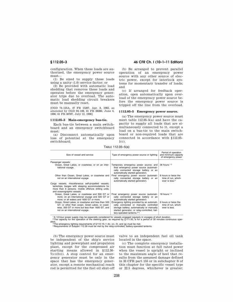
238
46 CFR Ch. I (10–1–11 Edition) § 112.05–3
configuration. When these loads are au-thorized, the emergency power source must—
(1) Be sized to supply these loads using a unity (1.0) service factor; or
(2) Be provided with automatic load shedding that removes these loads and operates before the emergency gener-ator trips due to overload. The auto-matic load shedding circuit breakers must be manually reset.
[CGD 74–125A, 47 FR 15267, Apr. 8, 1982, as amended by CGD 94–108, 61 FR 28286, June 4, 1996; 61 FR 36787, July 12, 1996]
§ 112.05–3 Main-emergency bus-tie. Each bus-tie between a main switch-
board and an emergency switchboard must:
(a) Disconnect automatically upon loss of potential at the emergency switchboard;
(b) Be arranged to prevent parallel operation of an emergency power source with any other source of elec-tric power, except for interlock sys-tems for momentary transfer of loads; and
(c) If arranged for feedback oper-ation, open automatically upon over-load of the emergency power source be-fore the emergency power source is tripped off the line from the overload.
§ 112.05–5 Emergency power source.
(a) The emergency power source must meet table 112.05–5(a) and have the ca-pacity to supply all loads that are si-multaneously connected to it, except a load on a bus-tie to the main switch-board or non-required loads that are connected in accordance with § 112.05– 1(c).
TABLE 112.05–5(a)
Size of vessel and service Type of emergency power source or lighting Period of operation
and minimum capacity of emergency power
Passenger vessels: Ocean, Great Lakes, or coastwise; or on an inter-
national voyage.Temporary emergency power source; and
final emergency power source (automati-cally connected storage battery or an automatically started generator).
36 hours.1 2
Other than Ocean, Great Lakes, or coastwise and not on an international voyage.
Final emergency power source (automati-cally connected storage battery or an automatically started generator).
8 hours or twice the time of run, which-ever is less.2
Cargo vessels; miscellaneous self-propelled vessels; tankships; barges with sleeping accommodations for more than 6 persons; mobile offshore drilling units; and oceanographic vessels:
Ocean, Great Lakes, or coastwise and 500 GT or more; on an international voyage and 500 GT or more; or all waters and 1600 GT or more.
Final emergency power source (automati-cally connected storage battery or an automatically started generator).
18 hours.1 2
Ocean, Great Lakes, or coastwise and less than 500 GT; or other than ocean, Great Lakes, or coast-wise, 300 GT or more but less than 1600 GT, and not on an international voyage..
Emergency lighting provided by an automati-cally connected or manually controlled storage battery; automatically or manually started generator; or relay-controlled, bat-tery-operated lanterns.3 4.
6 hours or twice the time of run, which-ever is less.
1 A 12-hour power supply may be especially considered for vessels engaged regularly in voyages of short duration. 2 The capacity for the operation of the steering gear, as required by § 111.93, is for a period of 30 minutes continuous oper-
ation. 3 The emergency lighting requirements of § 112.15–1 (b), (c), (f), and (g) must be met. 4 Requirements of Subpart 112.39 must be met by the relay-controlled, battery-operated lanterns.
(b) The emergency power source must be independent of the ship’s service lighting and powerplant and propulsion plant, except for the compressed air starting means allowed in § 112.50– 7(c)(3)(i). A stop control for an emer-gency generator must be only in the space that has the emergency gener-ator, except a remote mechanical reach rod is permitted for the fuel oil shut-off
valve to an independent fuel oil tank located in the space.
(c) The complete emergency installa-tion must function at full rated power when the vessel is upright or inclined to the maximum angle of heel that re-sults from the assumed damage defined in 33 CFR part 155 or in subchapter S of this chapter for the specific vessel type or 22.5 degrees, whichever is greater;
VerDate Mar<15>2010 08:26 Nov 18, 2011 Jkt 223196 PO 00000 Frm 00248 Fmt 8010 Sfmt 8010 Y:\SGML\223196.XXX 223196wre
ier-
avile
s on
DS
K3T
PT
VN
1PR
OD
with
CF
R

239
Coast Guard, DHS § 112.15–1
when the trim of the ship is 10 degrees, either in the fore or aft direction, or is in any combination of angles within those limits.
(d) The emergency power source, its associated transforming equipment, and the emergency switchboard must be located aft of the collision bulk-head, outside of the machinery casing, and above the uppermost continuous deck. Each compartment containing this equipment must be readily acces-sible from the open deck and must not contain machinery not associated with, or equipment not in support of, the normal operation of the emergency power source. Equipment in support of the normal operation of the emergency power source includes, but is not lim-ited to, ventilation fans, CO2 bottles, space heaters, and internal commu-nication devices, such as sound pow-ered phones.
(e) No compartment that has an emergency power source or its vital components may adjoin a Category A machinery space or those spaces con-taining the main source of electrical power and its vital components.
(f) Except for a cable for connecting equipment in the engineroom or boiler-room, no cable supplied from the emer-gency switchboard may penetrate the boundaries of the engineroom, boiler-room, uptakes, or casings of these spaces. These cables must be kept clear of the bulkheads and decks forming these boundaries. No emergency circuit in an engineroom or a boilerroom may supply equipment in any other space.
(g) The emergency switchboard must be as near as practicable to the emer-gency power source but not in the same space as a battery emergency power source.
(h) If the emergency power source is a generator, the emergency switch-board must be in the same space as the emergency power source.
(i) The prime mover of an emergency generator must be either a diesel en-gine or a gas turbine.
[CGD 74–125A, 47 FR 15267, Apr. 8, 1982, as amended by CGD 94–108, 61 FR 28286, June 4, 1996; 62 FR 23910, May 1, 1997]
Subpart 112.15—Emergency Loads
§ 112.15–1 Temporary emergency loads.
On vessels required by § 112.05–5(a) to have a temporary emergency power source, the following emergency light-ing and power loads must be arranged so that they can be energized from the temporary emergency power source:
(a) Navigation lights. (b) Enough lights throughout ma-
chinery spaces to allow essential oper-ations and observations under emer-gency conditions and to allow restora-tion of service.
(c) Lighting, including low location lighting if installed, for passageways, stairways, and escape trunks in pas-senger quarters, crew quarters, public spaces, machinery spaces, damage con-trol lockers, emergency equipment lockers, and work spaces sufficient to allow passengers and crew to find their way to open decks and to survival craft, muster stations, and embar-kation stations with all watertight doors and fire doors closed.
(d) Illuminated signs with the word ‘‘EXIT’’ in red letters throughout a passenger vessel so the direction of es-cape to the open deck is obvious from any portion of the vessel usually acces-sible to the passengers or crew, except machinery spaces, and except stores and similar spaces where the crew are not normally employed. There must be sufficient signs so that the direction of escape is obvious, with all fire doors in stairway enclosures and main vertical zone bulkheads closed and all water-tight doors closed. For the purpose of this paragraph, an individual state-room or other similar small room is not required to have a sign, but the di-rection of escape must be obvious to a person emerging from the room.
(e) Illumination to allow safe oper-ation of each power operated water-tight door.
(f) At least one light in each space where a person may be maintaining, re-pairing, or operating equipment, stow-ing or drawing stores or equipment, or transiting, such as public spaces, work spaces, machinery spaces, workshops, galleys, emergency fire pumprooms, bow thruster rooms, storage areas for
VerDate Mar<15>2010 08:26 Nov 18, 2011 Jkt 223196 PO 00000 Frm 00249 Fmt 8010 Sfmt 8010 Y:\SGML\223196.XXX 223196wre
ier-
avile
s on
DS
K3T
PT
VN
1PR
OD
with
CF
R

240
46 CFR Ch. I (10–1–11 Edition) § 112.15–5
paint, rope, and other stores, underdeck passageways in cargo areas, steering gear rooms, windlass rooms, normally accessible duct keels with valve operators, cargo handling rooms, and holds of roll-on/roll-off vessels.
(g) Lighting for survival craft launching, including muster stations, embarkation stations, the survival craft, its launching appliances and the area of the water where it is to be launched.
(h) Electric communication systems that are necessary under temporary emergency conditions and that do not have an independent storage battery source of power.
(i) Each power operated watertight door system.
(j) All shipwide communications sys-tems necessary for the transmittal of information during an emergency.
(k) Each fire door holding and release system.
(l) Supply to motor generator or other conversion equipment if a tem-porary emergency power source of al-ternating current is necessary for es-sential communication systems or emergency equipment.
(m) Each daylight signaling light. (n) Each smoke detector system. (o) Each electrically controlled or
powered ship’s whistle. (p) Each fire detection system; and
gas detection system if installed. (q) All lighting relative to helicopter
operations and landing if installed, un-less provided for by another source of power (such as independent batteries separately charged by solar cells).
(r) Each general emergency alarm system required by IMO SOLAS 74 (in-corporated by reference; see 46 CFR 110.10–1).
[CGD 74–125A, 47 FR 15267, Apr. 8, 1982, as amended by CGD 94–108, 61 FR 28286, June 4, 1996; USCG–2003–16630, 73 FR 65201, Oct. 31, 2008]
§ 112.15–5 Final emergency loads.
On vessels required to have a final emergency power source by § 112.05–5(a) of this chapter, the following emer-gency lighting and power loads must be arranged so that they can be energized from the final emergency power source:
(a) Each load under § 112.15–1.
(b) The machinery, controls, and alarms for each passenger elevator.
(c) Each charging panel for: (1) Temporary emergency batteries; (2) Starting batteries for diesel en-
gines or gas turbines that drive emer-gency generators; and
(3) General alarm batteries. (d) One of the bilge pumps, if the
emergency power source is its source of power to meet Part 56 of this chapter.
(e) One of the fire pumps, if the emer-gency power source is its source of power to meet the requirements of the subchapter under which the vessel is certificated.
(f) Each sprinkler system, water spray extinguishing system, or foam system pump.
(g) If necessary, the lube oil pump for each propulsion turbine and reduction gear, propulsion diesel reduction gear, and ship’s service generator turbine which needs external lubrication.
(h) Each rudder angle indicator. (i) Each radio or global maritime dis-
tress and safety system (GMDSS) com-ponent.
(j) Each radio direction finder, radar, gyrocompass, depth sounder, global po-sitioning system (GPS), satellite navi-gation system (SATNAV), speed log, rate-of-turn indicator and propeller pitch indicator.
(k) Each steering gear feeder, if re-quired by part 58, subpart 58.25, of this chapter.
(l) Each general emergency alarm flashing light required by § 113.25–10 of this chapter.
(m) Each electric blow-out-preventer control system.
(n) Any permanently installed diving equipment that is dependent upon the vessel’s or drilling unit’s power.
(o) Each emergency generator start-ing compressor, as allowed by § 112.50– 7(c)(3)(ii).
(p) Each steering gear failure alarm required by part 113, subpart 113.43, of this chapter.
(q) The ballast control system on each column-stabilized mobile offshore drilling unit.
(r) Each vital system automation load required by part 62 of this chapter.
(s) Motor-operated valves for each cargo oil and fuel oil system, if the emergency power source is the source
VerDate Mar<15>2010 08:26 Nov 18, 2011 Jkt 223196 PO 00000 Frm 00250 Fmt 8010 Sfmt 8010 Y:\SGML\223196.XXX 223196wre
ier-
avile
s on
DS
K3T
PT
VN
1PR
OD
with
CF
R

241
Coast Guard, DHS § 112.25–1
of power to meet § 56.60(d) of this chap-ter.
(t) Each ship’s stabilizer wing, unless a separate source of emergency power is supplied.
(u) Each indicator that shows the po-sition of the stabilizer wings, if the emergency power source is its emer-gency source of power.
(v) Each smoke extraction fan (not including smoke detector sampling) and CO2 exhaust fan for spaces.
[CGD 74–125A, 47 FR 15267, Apr. 8, 1982, as amended by CGD 94–108, 61 FR 28287, June 4, 1996; 61 FR 36787, July 12, 1996; USCG–2010– 0759, 75 FR 60003, Sept. 29, 2010]
§ 112.15–10 Loads on systems without a temporary emergency power source.
If there is no temporary emergency power source, the loads under § 112.15–1 must be arranged so that they can be energized from the final emergency power source.
Subpart 112.20—Emergency Sys-tems Having a Temporary and a Final Emergency Power Source
§ 112.20–1 General. This subpart contains requirements
applicable to emergency power instal-lations having both a temporary and a final emergency power source.
§ 112.20–3 Normal source for emer-gency loads.
(a) The normal source for emergency loads must be the ship’s service gener-ating plant.
(b) The power from the ship’s service generating plant for the emergency loads must be supplied to the emer-gency switchboard through automatic transfer switches.
§ 112.20–5 Failure of power from the normal source or final emergency power source.
(a) If there is a reduction of potential of the normal source by 15 to 40 per-cent, the loads under § 112.15–1 must be automatically supplied from the tem-porary emergency power source.
(b) For systems in which a reduction of frequency of the normal source or final emergency power source ad-
versely affects the emergency system and emergency loads, there must be means to transfer the loads under § 112.15–1 to the temporary emergency power source upon a reduction in the frequency of the normal source or final emergency power source.
§ 112.20–10 Diesel or gas turbine driv-en emergency power source.
Simultaneously with the operation of the transfer means under § 112.20–5, the diesel engine or gas turbine driving the final emergency power source must start automatically with no load on the final emergency power source.
§ 112.20–15 Transfer of emergency loads.
(a) When the potential of the final emergency power source reaches 85 to 95 percent of normal value, the emer-gency loads under § 112.15–5 must trans-fer automatically to the final emer-gency power source and, on a passenger vessel, this transfer must be accom-plished in no more than 45 seconds after failure of the normal source of power.
(b) When the potential from the nor-mal source has been restored, the emergency loads must be manually or automatically transferred to the nor-mal source, and the final emergency power source must be manually or automatically stopped.
(c) If the potential of the final emer-gency power source is less than 75 to 85 percent of normal value while sup-plying the emergency loads, the tem-porary emergency loads under § 112.15–1 must transfer automatically to the temporary emergency power source.
Subpart 112.25—Emergency Sys-tems Having an Automatic Starting Diesel Engine or Gas Turbine Driven Emergency Power Source as the Sole Emergency Power Source
§ 112.25–1 General. This subpart contains requirements
applicable to emergency power instal-lations having an automatic starting diesel engine or gas turbine driven emergency power source as the sole emergency power source.
VerDate Mar<15>2010 08:26 Nov 18, 2011 Jkt 223196 PO 00000 Frm 00251 Fmt 8010 Sfmt 8010 Y:\SGML\223196.XXX 223196wre
ier-
avile
s on
DS
K3T
PT
VN
1PR
OD
with
CF
R

242
46 CFR Ch. I (10–1–11 Edition) § 112.25–3
§ 112.25–3 Normal source for emer-gency loads.
(a) The normal source for emergency loads must be the ship’s service gener-ating plant.
(b) The power from the ship’s service generating plant for the emergency loads must be supplied to the emer-gency switchboard by an automatic transfer switch located at the emer-gency switchboard.
§ 112.25–5 Failure of power from the normal source.
If there is a reduction of potential of the normal source by 15 to 40 percent, the diesel engine or gas turbine driving the final emergency power source must start automatically with no load on the emergency power source.
§ 112.25–10 Transfer of emergency loads.
(a) When the potential of the final emergency source reaches 85 to 95 per-cent of normal value, the emergency loads under § 112.15–5 must transfer automatically to the final emergency power source and this transfer must be accomplished in no more than 45 sec-onds after failure of the normal source of power.
(b) When the potential from the nor-mal source has been restored, the emergency loads must be manually or automatically transferred to the nor-mal source, and the final emergency power source must be manually or automatically stopped.
Subpart 112.30—Emergency Sys-tems Having an Automatically Connected Storage Battery as the Sole Emergency Power Source
§ 112.30–1 General. This subpart contains requirements
applicable to emergency power instal-lations having an automatically con-nected storage battery as the sole emergency power source.
§ 112.30–3 Normal source for emer-gency loads.
(a) The normal source for emergency loads must be the ship’s service gener-ating plant.
(b) The power from the ship’s service generating plant for the emergency loads must be supplied to the emer-gency loads through automatic trans-fer switches.
§ 112.30–5 Transfer of emergency loads.
If there is a reduction of potential of the normal source by 15 to 40 percent, the emergency loads under § 112.15–5 must transfer automatically from the normal source to the emergency power source.
§ 112.30–10 Restoration of normal source potential.
When the potential from the normal source is restored to 85 to 95 percent of its normal value, the emergency loads must transfer automatically to the normal source.
Subpart 112.35—Manually Con-trolled Emergency Systems Having a Storage Battery or a Diesel Engine or Gas Turbine Driven Generator as the Sole Emergency Power Source
§ 112.35–1 General.
This subpart contains requirements applicable to emergency power instal-lations having a manually controlled storage battery, diesel engine, or gas turbine driven generator as the sole emergency power source.
§ 112.35–3 Normal source for emer-gency loads.
The normal source for emergency loads must be the ship’s service gener-ating plant.
§ 112.35–5 Manually started emergency systems.
Manually started emergency lighting and power systems must be activated by one manual operation, such as the manual operation of a switch from an ‘‘off’’ to an ‘‘on’’ position, to cause the emergency system to supply its con-nected loads.
§ 112.35–7 Activating means.
The activating means must be in the navigating bridge or in a location
VerDate Mar<15>2010 08:26 Nov 18, 2011 Jkt 223196 PO 00000 Frm 00252 Fmt 8010 Sfmt 8010 Y:\SGML\223196.XXX 223196wre
ier-
avile
s on
DS
K3T
PT
VN
1PR
OD
with
CF
R

243
Coast Guard, DHS § 112.43–7
where the means can be controlled by the chief engineer.
[CGD 74–125A, 47 FR 15267, Apr. 8, 1982, as amended by CGD 94–108, 61 FR 28287, June 4, 1996]
Subpart 112.37—Temporary Emergency Power Source
§ 112.37–1 General. Each temporary source of emergency
power required by Table 112.05–5(a) must consist of a storage battery of sufficient capacity to supply the tem-porary emergency loads for not less than one-half hour.
Subpart 112.39—Battery Operated Lanterns
§ 112.39–1 General. (a) Each battery-operated, relay-con-
trolled lantern used in accordance with Table 112.05–5(a) must:
(1) Have rechargeable batteries; (2) Have an automatic battery charg-
er that maintains the battery in a fully charged condition; and
(3) Not be readily portable.
[CGD 74–125A, 47 FR 15267, Apr. 8, 1982, as amended by CGD 94–108, 61 FR 28287, June 4, 1996]
§ 112.39–3 Operation. (a) The lanterns must be capable of
providing light for at least 3 hours. (b) The lantern must be relay-con-
trolled so that the loss of normal power causes the lanterns to light.
[CGD 74–125A, 47 FR 15267, Apr. 8, 1982, as amended by CGD 94–108, 61 FR 28287, June 4, 1996]
Subpart 112.40—Alternating-Cur-rent Temporary Source of Supply
§ 112.40–1 General requirements. Installations requiring alternating
current for the operation of commu-nication equipment or other apparatus essential under temporary emergency conditions must be provided with the necessary conversion equipment. If the conversion equipment operates both under normal conditions and under temporary emergency conditions, the
conversion equipment must be provided in duplicate.
Subpart 112.43—Emergency Lighting Systems
§ 112.43–1 Switches. An emergency lighting system must
not have a switch, except: (a) In a distribution panel; (b) As required in § 112.43–7; or (c) In a circuit that serves a haz-
ardous space such as a paint room or cargo handling room if the switch is lo-cated outside of the hazardous loca-tion.
[CGD 74–125A, 47 FR 15267, Apr. 8, 1982, as amended by CGD 94–108, 61 FR 28287, June 4, 1996]
§ 112.43–5 Controls on island type ves-sels.
On an island type vessel, such as a containership, emergency lights for il-lumination of survival craft launching operations must be controlled from a central location within the island near-est the launching operations or from the navigating bridge.
[CGD 74–125A, 47 FR 15267, Apr. 8, 1982, as amended by CGD 94–108, 61 FR 28287, June 4, 1996]
§ 112.43–7 Navigating bridge distribu-tion panel.
(a) Except as allowed in paragraph (b) of this section, the following emer-gency lights must be supplied from a distribution panel on the navigating bridge:
(1) Navigation lights not supplied by the navigation light indicator panel.
(2) Lights for survival craft launch-ing operations under § 111.75–16, except as allowed in § 112.43–5.
(3) Signaling lights. (4) Emergency lights: (i) On open decks; (ii) On the navigating bridge; (iii) In the chartroom; (iv) In the fire control room; and (v) For navigation equipment. (b) On a mobile offshore drilling unit,
the distribution panel required in para-graph (a) of this section must be in the control room.
(c) Each distribution panel required in paragraphs (a) and (b) of this section
VerDate Mar<15>2010 08:26 Nov 18, 2011 Jkt 223196 PO 00000 Frm 00253 Fmt 8010 Sfmt 8010 Y:\SGML\223196.XXX 223196wre
ier-
avile
s on
DS
K3T
PT
VN
1PR
OD
with
CF
R

244
46 CFR Ch. I (10–1–11 Edition) § 112.43–9
must have a fused switch or circuit breaker for each branch circuit.
[CGD 74–125A, 47 FR 15267, Apr. 8, 1982, as amended by CGD 94–108, 61 FR 28287, June 4, 1996]
§ 112.43–9 Signaling lights.
Each signaling light must be supplied by a branch circuit that supplies no other equipment.
§ 112.43–11 Illumination for launching operations.
Branch circuits supplying power to lights for survival craft launching op-erations must supply no other equip-ment and meet § 111.75–16 of this chap-ter.
[CGD 94–108, 61 FR 28287, June 4, 1996]
§ 112.43–13 Navigation light indicator panel supply.
Each navigation light indicator panel must be supplied:
(a) Directly from the emergency switchboard; or
(b) Be a through feed, without switch or overcurrent protection, from the feeder supply the navigating bridge emergency lighting panel.
[CGD 74–125A, 47 FR 15267, Apr. 8, 1982, as amended by CGD 94–108, 61 FR 28287, June 4, 1996]
§ 112.43–15 Emergency lighting feed-ers.
For a vessel with fire bulkheads forming fire zones, at least one emer-gency lighting feeder must supply only the emergency lights between two ad-jacent main vertical fire zone bulk-heads. The emergency lighting feeder must be separated as widely as prac-ticable from any general lighting feed-er supplying the same space.
[CGD 74–125A, 47 FR 15267, Apr. 8, 1982, as amended by CGD 94–108, 61 FR 28287, June 4, 1996]
Subpart 112.45—Visible Indicators
§ 112.45–1 Visible indicators.
There must be visible indicators in the machinery space to show;
(a) When an emergency battery is discharging; and
(b) When the automatically con-trolled emergency power source is sup-plying the emergency loads.
Subpart 112.50—Emergency Die-sel and Gas Turbine Engine Driven Generator Sets
§ 112.50–1 General. (a) The prime mover of a generator
set must have: (1) All accessories necessary for oper-
ation and protection of the prime mover; and
(2) A self-contained cooling system of a size that ensures continuous oper-ation with 100 degrees F (37 degrees C) air.
(b) The fuel used must have a flashpoint of not less than 110 degrees F (43 degrees C).
(c) The room that has the generator set must have intake and exhaust ducts to supply adequate cooling air.
(d) The generator set must be capable of carrying its full rated load within 45 seconds after cranking is started with the intake air, room ambient tempera-ture, and starting equipment at O°C. The generator’s prime mover must not have a starting aid to meet this re-quirement, except that a thermostatically-controlled electric water-jacket heater connected to the final emergency bus is permitted.
(e) The generator set must start by hydraulic, compressed air, or electrical means.
(f) The generator set must maintain proper lubrication when inclined to the angles specified in § 112.05–5(c), and must be arranged so that it does not spill oil under a vessel roll of 30 degrees to each side of the vertical.
(g) The generator set must shut down automatically upon loss of lubricating oil pressure, overspeed, or operation of a fixed fire extinguishing system in the emergency generator room (see § 111.12– 1(b) for detailed overspeed trip require-ments).
(h) If the prime mover is a diesel en-gine, there must be an audible alarm that sounds on low oil pressure and high cooling water temperature.
(i) If the prime mover is a gas tur-bine, it must meet the shutdown and alarm requirements in § 58.10–15(f) of this chapter.
VerDate Mar<15>2010 08:26 Nov 18, 2011 Jkt 223196 PO 00000 Frm 00254 Fmt 8010 Sfmt 8010 Y:\SGML\223196.XXX 223196wre
ier-
avile
s on
DS
K3T
PT
VN
1PR
OD
with
CF
R

245
Coast Guard, DHS § 112.55–1
(j) An independent fuel supply must be provided for the prime mover.
(k) Each emergency generator that is arranged to be automatically started must be equipped with a starting de-vice with an energy-storage capability of at least six consecutive starts. A second, separate source of starting en-ergy may provide three of the required six starts. If a second source is pro-vided, the system need only provide three consecutive starts.
[CGD 74–125A, 47 FR 15267, Apr. 8, 1982, as amended by CGD 94–108, 61 FR 28287, June 4, 1996; USCG–2004–18884, 69 FR 58348, Sept. 30, 2004]
§ 112.50–3 Hydraulic starting. A hydraulic starting system must
meet the following: (a) The hydraulic starting system
must be a self-contained system that provides the cranking torque and en-gine starting RPM recommended by the engine manufacturer. The hydrau-lic starting system must be capable of six consecutive starts, unless a second, separate source of starting energy ca-pable of three consecutive starts is pro-vided. A second, separate source of starting energy may provide three of the required six starts. If a second source is provided, the hydraulic sys-tem need only provide three consecu-tive starts.
(b) The stored hydraulic pressure must be automatically maintained within the predetermined pressure lim-its.
(c) The means of automatically maintaining the hydraulic system within the predetermined pressure lim-its must be electrically energized from the final emergency bus.
(d) There must be a means to manu-ally recharge the hydraulic system.
(e) Charging of the hydraulic starting system must not cause insufficient hy-draulic pressure for engine starting.
[CGD 74–125A, 47 FR 15267, Apr. 8, 1982, as amended by CGD 94–108, 61 FR 28287, June 4, 1996]
§ 112.50–5 Electric starting. An electric starting system must
have a starting battery with sufficient capacity for at least six consecutive starts. A second, separate source of starting energy may provide three of
the required six starts. If a second source is provided, the electrical start-ing system need only provide three consecutive starts.
[CGD 94–108, 61 FR 28288, June 4, 1996]
§ 112.50–7 Compressed air starting. A compressed air starting system
must meet the following: (a) The starting, charging, and en-
ergy storing devices must be in the emergency generator room, except for the main or auxiliary air compressors addressed in paragraph (c)(3)(i) of this section.
(b) The compressed air starting sys-tem must provide the cranking torque and engine starting RPM recommended by the engine manufacturer.
(c) The compressed air starting sys-tem must have an air receiver that meets the following:
(1) Has a capacity for at least six con-secutive starts. A second, separate source of starting energy may provide three of the required consecutive starts. If a second source is provided, the compressed air starting system need only provide three consecutive starts.
(2) Supplies no other system. (3) Is supplied from one of the fol-
lowing: (i) The main or auxiliary compressed
air receivers with a nonreturn valve in the emergency generator room and a handcranked, diesel-powered air com-pressor for recharging the air receiver.
(ii) An electrically driven air com-pressor that is automatically operated and is powered from the emergency power source. If this compressor sup-plies other auxiliaries, there must be a non-return valve at the inlet of the starting air receiver and there must be a handcranked, diesel-powered air com-pressor for recharging the air receiver.
[CGD 74–125A, 47 FR 15267, Apr. 8, 1982, as amended by CGD 94–108, 61 FR 28288, June 4, 1996]
Subpart 112.55—Storage Battery Installation
§ 112.55–1 General. Each storage battery installation
must meet Subpart 111.15 of this chap-ter.
VerDate Mar<15>2010 08:26 Nov 18, 2011 Jkt 223196 PO 00000 Frm 00255 Fmt 8010 Sfmt 8010 Y:\SGML\223196.XXX 223196wre
ier-
avile
s on
DS
K3T
PT
VN
1PR
OD
with
CF
R
246
46 CFR Ch. I (10–1–11 Edition) § 112.55–5
§ 112.55–5 Emergency lighting loads. When supplying emergency lighting
loads, the storage battery initial volt-age must not exceed the standard sys-tem voltage by more than 5 percent.
§ 112.55–10 Storage battery charging. (a) Each storage battery installation
for emergency lighting and power, and starting batteries for an emergency diesel or gas turbine driven generator set, must have apparatus to automati-cally maintain the battery fully charged.
(b) When the ship’s service gener-ating plant is available, the battery must have a continuous trickle charge, except that after discharge the battery must be charged automatically at a higher rate.
(c) Charging operations must not cause an absence of battery power.
(d) There must be instruments to show the rate of charge.
§ 112.55–15 Capacity of storage bat-teries.
(a) A storage battery for an emer-gency lighting and power system must have the capacity—
(1) To close all watertight doors two times;
(2) To open all watertight doors once; and
(3) To carry the remaining emer-gency loads continuously for the time prescribed in § 112.05–5(a), table 112.05– 5(a).
(b) At the end of the time specified in paragraph (a) of this section, the po-tential of the storage battery must be at least 88 percent of the standard volt-age.
[CGD 74–125A, 47 FR 15267, Apr. 8, 1982, as amended by CGD 94–108, 61 FR 28288, June 4, 1996; 61 FR 39695, July 30, 1996]
PART 113—COMMUNICATION AND ALARM SYSTEMS AND EQUIPMENT
Subpart 113.05—General Provisions
Sec. 113.05–5 Approved equipment. 113.05–7 Environmental tests.
Subpart 113.10—Fire and Smoke Detecting and Alarm Systems
113.10–1 Approved equipment.
113.10–3 Cable runs. 113.10–5 Common return. 113.10–7 Connection boxes. 113.10–9 Power supply.
Subpart 113.20—Automatic Sprinkler Systems
113.20–1 Sprinkler alarm system. 113.20–3 Connection boxes.
Subpart 113.25—General Emergency Alarm Systems
113.25–1 Applicability. 113.25–3 Requirements. 113.25–5 Location of contact makers. 113.25–6 Power supply. 113.25–7 Power supply overcurrent protec-
tion. 113.25–8 Distribution of general emergency
alarm system feeders and branch cir-cuits.
113.25–9 Location of general emergency alarm signal.
113.25–10 Emergency red-flashing lights. 113.25–11 Contact makers. 113.25–12 Alarm signals. 113.25–14 Electric cable and distribution fit-
tings. 113.25–15 Distribution panels. 113.25–16 Overcurrent protection. 113.25–20 Marking of equipment. 113.25–25 General emergency alarm systems
for manned ocean and coastwise barges. 113.25–30 General emergency alarm systems
for barges of 300 or more gross tons with sleeping accommodations for more than six persons.
Subpart 113.27—Engineers’ Assistance- Needed Alarm
113.27–1 Engineers’ assistance-needed alarm.
Subpart 113.30—Internal Communications
113.30–1 Applicability. 113.30–3 Means of communications. 113.30–5 Requirements. 113.30–20 General requirements. 113.30–25 Detailed requirements.
Subpart 113.35—Engine Order Telegraph Systems
113.35–1 Definitions. 113.35–3 General requirements. 113.35–5 Electric engine order telegraph sys-
tems. 113.35–7 Electric engine order telegraph sys-
tems; operations. 113.35–9 Mechanical engine order telegraph
systems. 113.35–13 Mechanical engine order telegraph
systems; operation. 113.35–15 Mechanical engine order telegraph
systems; application.
VerDate Mar<15>2010 08:26 Nov 18, 2011 Jkt 223196 PO 00000 Frm 00256 Fmt 8010 Sfmt 8010 Y:\SGML\223196.XXX 223196wre
ier-
avile
s on
DS
K3T
PT
VN
1PR
OD
with
CF
R

247
Coast Guard, DHS § 113.10–9
113.35–17 Vessels with navigating bridge control.
Subpart 113.37—Shaft Speed and Thrust Indicators
113.37–1 Applicability. 113.37–5 General requirements. 113.37–10 Detailed requirements.
Subpart 113.40—Rudder Angle Indicator Systems
113.40–1 Applicability. 113.40–5 General requirements. 113.40–10 Detailed requirements.
Subpart 113.43—Steering Failure Alarm Systems
113.43–1 Applicability. 113.43–3 Alarm system. 113.43–5 Power supply.
Subpart 113.45—Refrigerated Spaces Alarm Systems
113.45–5 General requirements.
Subpart 113.50—Public Address Systems
113.50–1 Applicability. 113.50–5 General requirements. 113.50–10 Additional requirements for pas-
senger vessels. 113.50–15 Loudspeakers. 113.50–20 Distribution of cable runs.
Subpart 113.65—Whistle Operators
113.65–5 General requirements.
AUTHORITY: 46 U.S.C. 3306, 3703; Depart-ment of Homeland Security Delegation No. 0170.1.
SOURCE: CGD 74–125A, 47 FR 15272, Apr. 8, 1982, unless otherwise noted.
Subpart 113.05—General Provisions
§ 113.05–5 Approved equipment. If approved equipment is required in
this part, that equipment must be spe-cifically approved by the Commandant.
NOTE: Many specifications for equipment that must be approved are in Subchapter Q for this chapter.
§ 113.05–7 Environmental tests. Communication, alarm system, con-
trol, and monitoring equipment must meet the environmental tests of—
(a) Section 4–9–7, Table 9, of ABS Steel Vessel Rules (incorporated by
reference; see 46 CFR 110.10–1) or the applicable ENV category of Lloyd’s Register Type Approval System—Test Specification Number 1 (incorporated by reference; see 46 CFR 110.10–1); and
(b) IEC 60533 (incorporated by ref-erence; see 46 CFR 110.10–1) as appro-priate.
[CGD 94–108, 61 FR 28288, June 4, 1996, as amended by 62 FR 23910, May 1, 1997; USCG– 2003–16630, 73 FR 65201, Oct. 31, 2008]
Subpart 113.10—Fire and Smoke Detecting and Alarm Systems
§ 113.10–1 Approved equipment. Each alarm annunciator, fire detec-
tor, test station, manual station, and vibrating bell must be approved under Subpart 161.002 of this chapter and meet the requirements of this subpart.
§ 113.10–3 Cable runs. Cable runs between the fire alarm an-
nunciator and fire detecting or fire alarm zones must be as direct as prac-ticable and, where practicable, must not be in staterooms, lockers, or other enclosed spaces in order to reduce the risk of damage by a localized fire or other cause.
§ 113.10–5 Common return. A conductor must not be used as a
common return from more than one zone.
§ 113.10–7 Connection boxes. Each connection box must be con-
structed in accordance with Type 4 or 4X of NEMA 250 or IP 56 of IEC 60529 (both incorporated by reference; see 46 CFR 110.10–1) requirements.
[USCG–2003–16630, 73 FR 65201, Oct. 31, 2008]
§ 113.10–9 Power supply. (a) General. There must be at least
two sources of power for the electrical equipment of each fire detecting and alarm system. The normal source must be the main power source. The other source must be the emergency power source or an automatically charged battery. If the other source is an auto-matically charged battery, the charger must be supplied from the final emer-gency power source. Upon loss of power to the system from the normal source,
VerDate Mar<15>2010 08:26 Nov 18, 2011 Jkt 223196 PO 00000 Frm 00257 Fmt 8010 Sfmt 8010 Y:\SGML\223196.XXX 223196wre
ier-
avile
s on
DS
K3T
PT
VN
1PR
OD
with
CF
R

248
46 CFR Ch. I (10–1–11 Edition) § 113.20–1
the system must be automatically sup-plied from the other source.
(b) Batteries. Each battery used in a fire detecting and alarm system must meet Subpart 111.15 of this chapter.
(c) Capacity of power supply branch circuit. The capacity of each branch cir-cuit providing power to a fire detection or alarm system must not be less than 125 percent of the maximum load.
[CGD 74–125A, 47 FR 15272, Apr. 8, 1982, as amended by CGD 94–108, 61 FR 28288, June 4, 1996]
Subpart 113.20—Automatic Sprinkler Systems
§ 113.20–1 Sprinkler alarm system.
Each sprinkler alarm system, includ-ing annunciator, power supply, alarm switches, and bells, must meet Subpart 76.25 of this chapter.
§ 113.20–3 Connection boxes.
Each connection box and each switch enclosure in an automatic sprinkler system must be constructed in accord-ance with Type 4 or 4X of NEMA 250 or IP 56 of IEC 60529 (both incorporated by reference; see 46 CFR 110.10–1) require-ments.
[USCG–2003–16630, 73 FR 65201, Oct. 31, 2008]
Subpart 113.25—General Emergency Alarm Systems
EDITORIAL NOTE: Nomenclature changes to subpart 113.25 appear at 61 FR 28288, June 4, 1996.
§ 113.25–1 Applicability.
(a) This subpart, except §§ 113.25–25 and 113.25–30, applies to each manned vessel of over 100 gross tons, except barges, scows, and similar vessels.
(b) Section 113.25–25 applies to each manned ocean and coastwise barge of over 100 gross tons if the crew is di-vided into watches for the purpose of steering.
(c) Section 113.25–30 applies to each barge of 300 or more gross tons that has sleeping accommodations for more than six persons.
§ 113.25–3 Requirements. Each vessel must have a general
emergency alarm system that meets the requirements of this subpart.
§ 113.25–5 Location of contact makers. (a) Passenger vessels and cargo and
miscellaneous vessels. Each passenger vessel, cargo vessel, and miscellaneous vessel must have a manually operated contact maker for the general emer-gency alarm system:
(1) In the navigating bridge; and (2) At the feeder distribution panel if
the general alarm power supply is not in or next to the navigating bridge.
(b) Tank vessels. Each tank vessel must have a manually operated con-tact maker for the general emergency alarm system:
(1) In the navigating bridge; (2) At the deck officers’ quarters far-
thest from the engineroom; (3) in the engineroom; (4) At the location of the emergency
means of stopping cargo transfer re-quired under 33 CFR 155.780; and
(5) At the feeder distribution panel if the general alarm power supply is not in or next to the navigating bridge.
(c) Mobile offshore drilling units. Each mobile offshore drilling unit must have a manually operated contact maker for the general emergency alarm system:
(1) In the main control room; (2) At the drilling console; (3) At the feeder distribution panel; (4) In the navigating bridge, if a navi-
gating bridge is installed; and (5) In a routinely occupied space that
is as far as practicable from all other contact makers.
(d) Additional contact maker. A vessel must not have more than one other contact maker that operates the gen-eral emergency alarm system in addi-tion to those required under paragraph (a), (b), or (c) of this section unless the installation of other contact makers has been accepted by the Commandant.
(e) Special system. If a vessel has an emergency squad when operating, has a manual fire alarm system, or is an ocean-going passenger vessel, it must have:
(1) An independent manually oper-ated contact maker in the navigating bridge that is connected to operate
VerDate Mar<15>2010 08:26 Nov 18, 2011 Jkt 223196 PO 00000 Frm 00258 Fmt 8010 Sfmt 8010 Y:\SGML\223196.XXX 223196wre
ier-
avile
s on
DS
K3T
PT
VN
1PR
OD
with
CF
R

249
Coast Guard, DHS § 113.25–9
only the general emergency alarm sig-nal in crew’s quarters and machinery spaces; or
(2) A separate alarm system that sounds in the crew’s quarters and ma-chinery spaces.
§ 113.25–6 Power supply.
The emergency power source for the general emergency alarm system must meet the requirements of IMO SOLAS 74 (incorporated by reference; see 46 CFR 110.10–1), Regulation II–1/42 or II–1/ 43, as applicable.
[USCG–2003–16630, 73 FR 65201, Oct. 31, 2008]
§ 113.25–7 Power supply overcurrent protection.
(a) If the general emergency alarm system is the only load supplied by the general emergency alarm system bat-tery or batteries, the battery or bat-teries must have an enclosed fused switch or circuit breaker that has a means of locking. The fused switched or circuit breaker must be outside of, and next to, the battery room or bat-tery locker, and the capacity of the fuses or circuit breaker must be at least 200 percent of the connected load.
(b) If the general emergency alarm system is supplied from an emergency or interior communication switch-board, or if duplicate general alarm batteries supply other loads as allowed under § 113.25–6(e)(2), there must be a fused switch or circuit breaker sup-plying the general emergency alarm system that has a means of locking.
§ 113.25–8 Distribution of general emergency alarm system feeders and branch circuits.
(a) Each system must have a feeder distribution panel to divide the system into the necessary number of zone, feeders, except where, because of the arrangement of the vessel, only one zone feeder is necessary; then a branch circuit distribution panel or feeder dis-tribution panel must be used.
(b) The feeder distribution panel must have overcurrent protection for each zone feeder, but there must be no disconnect switches.
(c) The feeder distribution panel must be in an enclosed space next to the general alarm power supply.
(d) Each system must have at least one feeder for each vertical fire zone that has general emergency alarm sig-nal.
(e) Each system must have one or more branch circuit distribution panels for each zone feeder, with at least one fused branch circuit for each deck level. The distribution panel must be above the uppermost continuous deck, in the zone served, and there must be no disconnect switches for the branch circuits.
(f) A branch circuit must not supply emergency alarm signal on more than one deck level, except for a single branch circuit supplying all levels of a single space containing more than one deck level if all other requirements of this section are met.
(g) On a vessel not divided into fire zones by main vertical fire bulkheads, the general emergency alarm system must be arranged into vertical service zones not more than 40 meters (131 feet) long, and there must be a general alarm feeder for each of these zones that has general emergency alarm sig-nal.
(h) General alarm feeders and branch circuit cables must be in passageways and must not be in staterooms, lock-ers, galleys, machinery spaces, or other enclosed spaces, unless it is necessary to supply general emergency alarm sig-nal in those spaces.
[CGD 74–125A, 47 FR 15272, Apr. 8, 1982, as amended by CGD 94–108, 61 FR 28288, June 4, 1996]
§ 113.25–9 Location of general emer-gency alarm signal.
General emergency alarm signal must:
(a) Be located in passenger and crew quarters areas where they can alert persons in spaces where those persons may be maintaining, repairing, or oper-ating equipment, stowing or drawing stores or equipment, or transiting, such as public spaces, work spaces, ma-chinery spaces, workshops, galleys, emergency firepump room, bow thrust-er rooms, storage areas for paint, rope, and other stores, underdeck passage-ways in cargo areas, steering gear rooms, windless rooms, holds of roll-on/ roll-off vessels, and, except those that are accessible only through bolted
VerDate Mar<15>2010 08:26 Nov 18, 2011 Jkt 223196 PO 00000 Frm 00259 Fmt 8010 Sfmt 8010 Y:\SGML\223196.XXX 223196wre
ier-
avile
s on
DS
K3T
PT
VN
1PR
OD
with
CF
R

250
46 CFR Ch. I (10–1–11 Edition) § 113.25–10
manhole covers, duct keels with valve operators; and
(b) Be audible in the spaces identified in paragraph (a) of this section with all normally closed doors and accesses closed; and
(c) Be installed in cabins without loudspeaker installation. Other audible devices, such as electronic alarm trans-ducers, are permitted.
[CGD 74–125A, 47 FR 15272, Apr. 8, 1982, as amended by CGD 94–108, 61 FR 28288, June 4, 1996]
§ 113.25–10 Emergency red-flashing lights.
(a) In a space described in § 113.25– 9(a), where the general emergency alarm signal cannot be heard over the background noise, there must be a red- flashing light or rotating beacon, in ad-dition to the general emergency alarm signal, that:
(1) Has sufficient intensity above the background lighting that would alert personnel in the space;
(2) Is activated whenever the general emergency alarm signal in the space are activated; and
(3) Is supplied by the general emer-gency alarm system power supply or the vessel emergency power source through a relay that is operated by the general emergency alarm system.
(b) A red-flashing light or rotating beacon must be installed so that it is visible in the cargo pump rooms of ves-sels that carry combustible liquid car-goes. The installation must be in ac-cordance with the requirements of part 111, subpart 111.105, of this chapter.
[CGD 74–125A, 47 FR 15272, Apr. 8, 1982, as amended by CGD 94–108, 61 FR 28288, June 4, 1996; 62 FR 23910, May 1, 1997]
§ 113.25–11 Contact makers. Each contact maker must— (a) Have normally open contacts and
be constructed in accordance with Type 4 or 4X of NEMA 250 or IP 56 of IEC 60529 (both incorporated by ref-erence; see 46 CFR 110.10–1) require-ments;
(b) Have a switch handle that can be maintained in the ‘‘on’’ position;
(c) Have the ‘‘off’’ and ‘‘on’’ positions of the operating handle permanently marked; and
(d) Have an inductive load rating not less than the connected load or, on large vessels, have auxiliary devices to interrupt the load current.
[CGD 94–108, 61 FR 28288, June 4, 1996, as amended at 62 FR 23910, May 1, 1997; USCG– 2003–16630, 73 FR 65201, Oct. 31, 2008]
§ 113.25–12 Alarm signals. (a) Each general emergency alarm
signal must be an electrically-operated bell, klaxon, or other warning device capable of producing a signal or tone distinct from any other audible signal on the vessel.
(b) Electronic devices used to produce the general emergency alarm signal must meet the requirements of subpart 113.50 of this part.
(c)(1) The minimum sound-pressure levels for the emergency-alarm tone in interior and exterior spaces must be a sound level of not less than 80 dB(A) measured at 10 feet on the axis; and
(2) At least 10 dB(A) measured at 10 feet on the axis, above the background noise level when the vessel is underway in moderate weather unless flashing red lights are used in accordance with 46 CFR 113.25–10(b).
(d) Alarm signals intended for use in sleeping compartments may have a minimum sound level of 75 dB(A) meas-ured 3 feet (1 meter) on axis, and at least 10 dB(A) measured 3 feet (1 meter) on axis, above ambient noise levels with the ship under way in moderate weather.
[CGD 94–108, 61 FR 28289, June 4, 1996, as amended by USCG–2003–16300, 73 FR 65201, Oct. 31, 2008]
§ 113.25–14 Electric cable and distribu-tion fittings.
Each cable entrance to an emergency alarm signal or distribution fitting must be made watertight by a terminal or stuffing tube.
§ 113.25–15 Distribution panels. Each distribution panel must: (a) Be watertight; (b) Need a tool to be opened.
§ 113.25–16 Overcurrent protection. (a) Each fuse in a general emergency
alarm system must meet the require-ments of part 111, subpart 111.53, of this chapter.
VerDate Mar<15>2010 08:26 Nov 18, 2011 Jkt 223196 PO 00000 Frm 00260 Fmt 8010 Sfmt 8010 Y:\SGML\223196.XXX 223196wre
ier-
avile
s on
DS
K3T
PT
VN
1PR
OD
with
CF
R

251
Coast Guard, DHS § 113.27–1
(b) Each overcurrent protection de-vice must cause as wide a differential as possible between the rating of the branch circuit overcurrent protection device and that of the feeder overcur-rent protection device.
(c) The capacity of the feeder over-current device must be as near prac-ticable to 200 percent of the load sup-plied. The capacity of a branch circuit overcurrent device must not be higher than 50 percent of the capacity of the feeder overcurrent device.
[CGD 94–108, 61 FR 28289, June 4, 1996]
§ 113.25–20 Marking of equipment. (a) Each general emergency alarm
system fused switch and distribution panel must have a fixed nameplate on the outside of its cover that has a de-scription of its function. The rating of fuses must also be shown on the out-side of the cover of a fused switch.
(b) Each general alarm contact maker must be marked ‘‘GENERAL ALARM’’ in red letters on a corrosion- resistant plate or on a sign.
(c) A contact maker that operates only the general emergency alarm sig-nal in crew quarters, machinery spaces, and work spaces must be marked ‘‘CREW ALARM’’ by the method de-scribed in paragraph (b) of this section.
(d) Each general emergency alarm signal must be marked ‘‘GENERAL ALARM—WHEN EMERGENCY ALARM SIGNAL RINGS GO TO YOUR STATION’’ in red letters at least 1⁄2 inch high.
(e) Each general emergency alarm system distribution panel must have a directory attached to the inside of its cover giving the designation of each circuit, the area supplied by each cir-cuit, and the rating of each circuit fuse.
[CGD 74–125A, 47 FR 15272, Apr. 8, 1982, as amended by USCG–2004–18884, 69 FR 58348, Sept. 30, 2004]
§ 113.25–25 General emergency alarm systems for manned ocean and coastwise barges.
A manned ocean or coastwise barge of more than 100 gross tons, if it is one that operates with the crew divided into watches for steering the vessel, must have an emergency alarm signal installation. The system must:
(a) Have an automatically charged battery as the power source;
(b) Have a manually operated contact maker at the steering station and in the crew accommodation area; and
(c) Must meet the requirements of § 113.25.7 and §§ 113.25–9 through 113.25–20 of this subpart.
§ 113.25–30 General emergency alarm systems for barges of 300 or more gross tons with sleeping accom-modations for more than six per-sons.
The general emergency alarm system for a barge of 300 or more gross tons with sleeping accommodations for more than six persons must meet the requirements of Subpart 113.25, except as follows:
(a) The number and location of con-tact makers must be determined by the design, service, and operation of the barge.
NOTE: Contact makers in the primary work area, quarters area, galley and mess area, machinery spaces, and the navigating bridge or control area should be considered.
(b) If a distribution panel cannot be above the uppermost continuous deck because of the design of the barge and is installed below the deck, it must be as near the deck as practicable.
[CGD 74–125A, 47 FR 15272, Apr. 8, 1982, as amended by CGD 94–108, 61 FR 28289, June 4, 1996]
Subpart 113.27—Engineers’ Assistance-Needed Alarm
§ 113.27–1 Engineers’ assistance-need-ed alarm.
Each self-propelled ocean, Great Lakes, or coastwise vessel must have a manually-operated engineers’ assist-ance-needed alarm that is:
(a) Operated from: (1) The engine control room, if the
vessel has an engine control room; or (2) The maneuvering platform, if the
vessel has no engine control room; (b) Audible in the engineers’ accom-
modation spaces; and (c) Powered from the general alarm
power source.
VerDate Mar<15>2010 08:26 Nov 18, 2011 Jkt 223196 PO 00000 Frm 00261 Fmt 8010 Sfmt 8010 Y:\SGML\223196.XXX 223196wre
ier-
avile
s on
DS
K3T
PT
VN
1PR
OD
with
CF
R

252
46 CFR Ch. I (10–1–11 Edition) § 113.30–1
Subpart 113.30—Internal Communications
§ 113.30–1 Applicability. This subpart applies to each self-pro-
pelled vessel.
§ 113.30–3 Means of communications. (a) An emergency means of commu-
nication required by this subpart must—
(1) Be comprised of either fixed or portable equipment; and
(2) Provide common talking means of two-way voice communication and calling among the navigating bridge, emergency control stations, muster stations, embarkation stations, and other strategic positions listed in § 113.30–5.
(b) The means of communication and calling must be a reliable means of voice communication and must be independent of the vessel’s electrical system.
[CGD 94–108, 61 FR 28289, June 4, 1996, as amended by USCG–2003–16630, 73 FR 65201, Oct. 31, 2008]
§ 113.30–5 Requirements. (a) Communication. Each vessel must
have a means of communication among the following:
(1) Navigating bridge. (2) Steering gear room, if outside the
engineroom. (3) Alternative steering station if
outside of the steering gear room. (4) Engine control room, if the vessel
has an engine control room. (5) Maneuvering platform, if the ves-
sel has no engine control room. (6) Control room, if the vessel is a
mobile offshore drilling unit. (7) The engineering officers’ accom-
modations, if the vessel is an auto-mated, self-propelled vessel under § 62.50–20(f) of this chapter.
(b) Gyrocompass. Each vessel that has a master gyrocompass that is not in or next to the navigating bridge must have a means of communication be-tween the master gyrocompass and the navigating bridge repeater compass.
(c) Radar. Each vessel that has a radar plan position indicator that is not in or next to the navigating bridge must have a means of communication
between the navigating bridge and the radar plan position indicator.
(d) Emergency lockers. If the emer-gency equipment lockers or spaces used by the emergency squad are not next to the navigating bridge or, on a mobile offshore drilling unit, next to the con-trol room, there must be a means of communication between the navi-gating bridge or control room and the emergency equipment lockers or spaces.
(e) Radio and radio direction finder. Communication to the radio and radio direction finder must meet the fol-lowing requirements:
(1) Each vessel that has a radio in-stallation must have a means of com-munication between the radio room, the navigating bridge, or, if the vessel is a mobile offshore drilling unit, the control room, and any other place from which the vessel may be navigated under normal conditions, other than a place that is only for emergency func-tions, a place that is only for docking or maneuvering, or a place that is for navigating the vessel in close quarters. A location that has the apparatus that is necessary to steer the vessel, give engine orders, and control the whistle, is a place from which the vessel may be navigated.
(2) If the operating position of the emergency radio installation is not in the compartment normally used for op-erating the main radio installation, there must be means of communication between the emergency radio room, the navigating bridge, or, if the vessel is a mobile offshore drilling unit, the con-trol room, and any other place from which the vessel may be navigated under normal conditions; other than a place that is only for emergency func-tions, a place that is only for docking or maneuvering, or a place that is for navigating the vessel in close quarters.
(3) Each vessel equipped with radio direction-finding apparatus that is not in or next to the navigating bridge must have a means of communication between the navigating bridge and the direction-finding apparatus.
(4) The communication system re-quired by this paragraph must be inde-pendent of all other systems on the vessel. The location of the termination of these systems is subject to approval
VerDate Mar<15>2010 08:26 Nov 18, 2011 Jkt 223196 PO 00000 Frm 00262 Fmt 8010 Sfmt 8010 Y:\SGML\223196.XXX 223196wre
ier-
avile
s on
DS
K3T
PT
VN
1PR
OD
with
CF
R

253
Coast Guard, DHS § 113.30–25
by the Federal Communication Com-mission.
(f) Fire or smoke detecting systems. Each vessel equipped with a fire or smoke detecting system, if control units are not in the navigating bridge, must have means of communication between the navigating bridge and the stations where the control units are lo-cated.
(g) Lookout. Each vessel must have a means of communication between the navigating bridge and the bow or for-ward lookout station unless direct voice communication is possible.
(h) Engineroom local control station. Each self-propelled vessel equipped with control from the navigating bridge must have a means of commu-nication between the local station for the control of the speed or direction of thrust of the propulsion machinery and the engine control room, unless an en-gine order telegraph is installed in ac-cordance with § 113.35–3. Each commu-nication station at a local control sta-tion must—
(1) Be on a circuit separate from any other station required by this section; and
(2) Provide the capability of reliable voice communication when the vessel is underway.
(i) Mobile offshore drilling units. Each non-self-propelled mobile offshore drilling unit must have a means of communication among the control room, drill floor, machinery space, and silicon controlled rectifier (SCR) room (if installed). Each column-stabilized mobile offshore drilling unit must have a means of communication between the ballast control room and the spaces that contain the ballast pumps and valves.
[CGD 74–125A, 47 FR 15272, Apr. 8, 1982, as amended by CGD 94–108, 61 FR 28289, June 4, 1996; 62 FR 23910, May 1, 1997; USCG–2004– 18884, 69 FR 58348, Sept. 30, 2004]
§ 113.30–20 General requirements. (a) The communications stations list-
ed in § 113.30–5(a) through (d), (f), (g), and (i) and other communications sta-tions for the operation of the vessel, such as the captain’s and chief engi-neer’s offices and staterooms, emer-gency power room, carbon dioxide (or other extinguishing agent) control
room, and firepump room, must not be on the same circuit as communications stations installed to meet the require-ments of §§ 113.30–5(e) and 113.30–5(h).
(b) If a communications station is in the weather and on the same circuit as other required stations, there must be a cut-out switch on the navigating bridge that can isolate this station from the rest of the stations, unless the system possesses other effective means of station isolation during a fault condition.
(c) No jack-box or headset may be on a communication system that includes any station required by this subpart, except for a station installed to meet 46 CFR 113.30–5(h) or 46 CFR 113.30–25(f).
[CGD 94–108, 61 FR 28289, June 4, 1996, as amended by USCG–2003–16630, 73 FR 65201, Oct. 31, 2008]
§ 113.30–25 Detailed requirements.
(a) Multiple stations must be able to communicate at the same time.
(b) The loss of one component of the system must not disable the rest of the system.
(c) The system must be able to oper-ate under full load for the same period of operation as required for the emer-gency generator. See 46 CFR 112.05–5, Table 112.05–5(a).
(d) Each voice-communication sta-tion device in the weather must be in a proper enclosure as required in 46 CFR 111.01–9. The audible-signal device must be outside the station enclosure.
(e) Each station in a navigating bridge or a machinery space must be in an enclosure meeting at least Type 2 of NEMA 250 or IP 22 of IEC 60529 (both in-corporated by reference; see 46 CFR 110.10–1).
(f) In a noisy location, such as an en-gine room, there must be a booth or other equipment to permit reliable voice communication while the vessel is operating.
(g) In a space throughout which the voice communication station audible- signal device cannot be heard, there must be another audible-signal device or a visual-device, such as a light, ei-ther of which is energized from the final emergency bus.
(h) If two or more voice communica-tion stations are near each other, there
VerDate Mar<15>2010 08:26 Nov 18, 2011 Jkt 223196 PO 00000 Frm 00263 Fmt 8010 Sfmt 8010 Y:\SGML\223196.XXX 223196wre
ier-
avile
s on
DS
K3T
PT
VN
1PR
OD
with
CF
R

254
46 CFR Ch. I (10–1–11 Edition) § 113.35–1
must be a means that indicates the sta-tion called.
(i) Each connection box must meet at least Type 4 or 4X of NEMA 250 or IP 56 of IEC 60529.
(j) Voice communication cables must run as close to the fore-and-aft center-line of the vessel as practicable.
(l) No cable for voice communication may run through any space at high risk of fire such as machinery rooms and galleys, unless it is technically im-practicable to route it otherwise or it must serve circuits within those spaces.
(2) Each cable running through any space at high risk of fire must meet IEC 60331–11 and IEC 60331–21 (both in-corporated by reference; see 46 CFR 110.10–1).
(k) If the communications system uses a sound-powered telephone, the following requirements also apply:
(1) Each station except one regulated by paragraph (d) of this section must include a permanently wired handset with a push-to-talk button and a hang-er for the handset.
(2) The hanger must be constructed so that it holds the handset away from the bulkhead and so that the motion of the vessel will not dislodge the handset.
(3) Each talking circuit must be elec-trically independent of each calling circuit.
(4) No short circuit, open circuit, or ground on either side of a calling cir-cuit may affect a talking circuit.
(5) Each circuit must be insulated from ground.
[USCG–2003–16630, 73 FR 65201, Oct. 31, 2008]
Subpart 113.35—Engine Order Telegraph Systems
§ 113.35–1 Definitions.
As used in this subpart: (a) Indicator means an instrument in
the engine room to receive and ac-knowledge engine orders; and
(b) Transmitter means an instrument to send engine orders to the engineroom and receive acknowledge-ment from the engineroom.
§ 113.35–3 General requirements. (a) Each self-propelled vessel, except
as provided in paragraph (d) of this sec-tion, must have an electric or mechan-ical engine order telegraph system from the navigating bridge to the engineroom.
(b) On a vessel with more than one propulsion engine, each engine must have this system.
(c) On a double-ended vessel that has two navigating bridges, this system must be between the engineroom and each navigating bridge.
(d) If a small vessel has no engine order telegraph system between the navigating bridge and the engineroom, the propulsion plant must be con-trolled entirely from the navigating bridge, with no means of normal engine control from the engineroom.
(e) On vessels equipped with pilot-house control, each local control sta-tion in the engineroom must have an indicator if:
(1) Manual operation from the local control station is an alternative means of control; and
(2) The local control station is not immediately adjacent to the engineroom control station; and
(3) Reliable voice communication and calling that meets the requirements of § 113.30–5(h) is not provided.
(f) Engine order telegraph and remote propulsion control systems must be electrically separate and independent, except that a single mechanical oper-ator control device with separate transmitters and connections for each system may be used.
[CGD 74–125A, 47 FR 15272, Apr. 8, 1982, as amended by CGD 81–030, 53 FR 17847, May 18, 1988; CGD 94–108, 61 FR 28290, June 4, 1996]
§ 113.35–5 Electric engine order tele-graph systems.
(a) Each electric engine order tele-graph system must have transmitters and indicators that are electrically connected to each other.
(b) Each engineroom indicator must be capable of acknowledgment of or-ders.
(c) There must be an audible signal at each instrument. The signal at both locations must sound continuously when the transmitter and the indicator do not show the same order.
VerDate Mar<15>2010 08:26 Nov 18, 2011 Jkt 223196 PO 00000 Frm 00264 Fmt 8010 Sfmt 8010 Y:\SGML\223196.XXX 223196wre
ier-
avile
s on
DS
K3T
PT
VN
1PR
OD
with
CF
R

255
Coast Guard, DHS § 113.35–17
(d) Each telegraph instrument must meet the protection requirements of § 111.01–9 of this chapter.
(e) Each system must have an alarm which—
(1) Automatically sounds and vis-ually signals a loss of power to the sys-tem;
(2) Is on the navigating bridge; and (3) Has a means to reduce the audible
signal from 100 percent to not less than 50 percent.
[CGD 74–125A, 47 FR 15272, Apr. 8, 1982, as amended by CGD 94–108, 61 FR 28290, June 4, 1996]
§ 113.35–7 Electric engine order tele-graph systems; operations.
(a) Where two or more transmitters, located on or on top of, or on the wings of, the navigating bridge operate a common indicator in the engineroom, the transmitters must:
(1) Operate in synchronism as re-quired in paragraph (b) of this section; or
(2) Operate under the control of a transmitter transfer control in accord-ance with paragraph (c) of this section.
(b) All transmitter handles and pointers must operate in synchronism. Where the transmitters are mechani-cally interlocked to effect synchronous operation, the requirements of § 113.35– 13 must be met.
(c) Except for a transmitter in an un-attended navigating bridge on a dou-ble-ended vessel, each transmitter must operate under the control of a transmitter transfer control so that movement of any one transmitter han-dle automatically connects that trans-mitter electrically to the engineroom indicator and simultaneously dis-connects electrically all other trans-mitters. The reply pointers of all trans-mitters must operate in synchronism at all times.
(d) On a double-ended vessel that has two navigating bridges, a manually op-erated transfer switch which will dis-connect the system in the unattended navigating bridge must be provided.
[CGD 74–125A, 47 FR 15272, Apr. 8, 1982. Redes-ignated and amended by CGD 94–108, 61 FR 28290, June 4, 1996]
§ 113.35–9 Mechanical engine order telegraph systems.
(a) Each mechanical engine order telegraph system must consist of transmitters and indicators mechani-cally connected to each other, as by means of chains and wires.
(b) Each transmitter and each indi-cator must have an audible signal de-vice to indicate, in the case of an indi-cator, the receipt of an order, and in the case of a transmitter, the acknowl-edgment of an order. The audible signal device must not be dependent upon any source of power for operation other than that of the movement of the transmitter or indicator handle.
[CGD 74–125A, 47 FR 15272, Apr. 8, 1982, as amended by CGD 94–108, 61 FR 28290, June 4, 1996]
§ 113.35–13 Mechanical engine order telegraph systems; operation.
If more than one transmitter oper-ates a common indicator in the engineroom, all the transmitters must be mechanically interlocked and oper-ate in synchronism. A failure of the transmission wire or chain at any transmitter must not interrupt or dis-able any other transmitter.
§ 113.35–15 Mechanical engine order telegraph systems; application.
If a mechanical engine order tele-graph system is installed on any vessel to provide the communication required by this subpart, the length of cables or other mechanical limitations must not prevent the efficient operation of the system.
§ 113.35–17 Vessels with navigating bridge control.
Each vessel with navigating bridge throttle control must have a positive mechanical stop on each telegraph transmitter that prevents movement to the ‘‘Navigating Bridge Control’’ po-sition without positive action by the operator.
[CGD 74–125A, 47 FR 15272, Apr. 8, 1982, as amended by CGD 94–108, 61 FR 28290, June 4, 1996]
VerDate Mar<15>2010 08:26 Nov 18, 2011 Jkt 223196 PO 00000 Frm 00265 Fmt 8010 Sfmt 8010 Y:\SGML\223196.XXX 223196wre
ier-
avile
s on
DS
K3T
PT
VN
1PR
OD
with
CF
R

256
46 CFR Ch. I (10–1–11 Edition) § 113.37–1
Subpart 113.37—Shaft Speed and Thrust Indicators
§ 113.37–1 Applicability.
This subpart applies to all self-pro-pelled vessels.
§ 113.37–5 General requirements.
(a) A vessel equipped with fixed pitch propellers must have on the navigating bridge and at the engineroom control station a propeller speed and direction indicator for each shaft.
(b) A vessel equipped with control-lable pitch propellers must have on the navigating bridge and at the engineroom control station a propeller speed and pitch position indicator for each shaft.
[CGD 74–125A, 47 FR 15272, Apr. 8, 1982, as amended by CGD 94–108, 61 FR 28290, June 4, 1996]
§ 113.37–10 Detailed requirements.
(a) Each indicator must be inde-pendent of the propulsion control sys-tem. A failure of the propulsion control system must not affect the operation of the indicators.
(b) Each electric component or its enclosure must meet Type 4 or 4X of NEMA 250 or IP 56 of IEC 60529 (both in-corporated by reference; see 46 CFR 110.10–1) requirements.
[CGD 74–125A, 47 FR 15272, Apr. 8, 1982, as amended by CGD 94–108, 61 FR 28290, June 4, 1996; USCG–2003–16630, 73 FR 65202, Oct. 31, 2008]
Subpart 113.40—Rudder Angle Indicator Systems
§ 113.40–1 Applicability.
This subpart applies to self-propelled vessels.
§ 113.40–5 General requirements.
The position of the rudder, if power- operated, must be shown at the prin-cipal steering station. If there is non- follow-up steering control at the alter-native steering station, there must be a separate rudder angle indicator sys-tem for that station that is electrically independent from each other rudder angle indicator system.
§ 113.40–10 Detailed requirements.
(a) Each rudder angle indicator sys-tem must have a transmitter at the rudder head that is actuated by move-ment of the rudder with the angular movements of the rudder transmitted to a remote indicator or indicators. This system must be independent of all other systems and not receive power or signal from the steering gear control, autopilot, or dynamic positioning sys-tems. However, the indicator may be physically located on a control console, such as an integrated bridge system, if it is readily visible by the helmsman at the steering stand.
(b) Each electric component or its enclosure must meet Type 4 or 4X of NEMA 250 or IP 56 of IEC 60529 (both in-corporated by reference; see 46 CFR 110.10–1) requirements.
[CGD 74–125A, 47 FR 15272, Apr. 8, 1982, as amended by CGD 94–108, 61 FR 28290, June 4, 1996; 62 FR 23910, May 1, 1997; USCG–2003– 16630, 73 FR 65202, Oct. 31, 2008]
Subpart 113.43—Steering Failure Alarm Systems
§ 113.43–1 Applicability.
This subpart applies to each vessel of 1600 gross tons and over that has power driven main or auxiliary steering gear.
§ 113.43–3 Alarm system.
(a) Each vessel must have a steering failure alarm system that actuates an audible and visible alarm in the pilot-house when the actual position of the rudder differs by more than 5 degrees from the rudder position ordered by the followup control systems, required by part 58, subpart 58.25, of this chapter, for more than:
(1) 30 seconds for ordered rudder posi-tion changes of 70 degrees;
(2) 6.5 seconds for ordered rudder po-sition changes of 5 degrees; and
(3) The time period calculated by the following formula for ordered rudder positions changes between 5 degrees and 70 degrees:
t = (R/2.76)+4.64
Where
t = maximum time delay in seconds R = ordered rudder change in degrees
VerDate Mar<15>2010 08:26 Nov 18, 2011 Jkt 223196 PO 00000 Frm 00266 Fmt 8010 Sfmt 8010 Y:\SGML\223196.XXX 223196wre
ier-
avile
s on
DS
K3T
PT
VN
1PR
OD
with
CF
R

257
Coast Guard, DHS § 113.50–5
(b) The alarm system must be sepa-rate from, and independent of, each steering gear control system, except for input received from the steering wheel shaft.
[CGD 74–125A, 47 FR 15272, Apr. 8, 1982, as amended by CGD 94–108, 62 FR 23910, May 1, 1997; USCG–2004–18884, 69 FR 58348, Sept. 30, 2004]
§ 113.43–5 Power supply.
Each steering failure alarm system must be supplied by a circuit that:
(a) Is independent of other steering gear system and steering alarm cir-cuits;
(b) Is fed from the final emergency power source through the emergency distribution panel in the wheelhouse, if installed; and
(c) Has no overcurrent protection ex-cept short-circuit protection by an in-stantaneous fuse or circuit breaker rated or set at 400 to 500 percent of:
(1) The current-carrying capacity of the smallest alarm system inter-connecting conductors; or
(2) The normal load of the system.
Subpart 113.45—Refrigerated Spaces Alarm Systems
§ 113.45–5 General requirements.
(a) Each refrigerated space that is ac-cessible to the vessel’s personnel and that can be locked from the outside so that it cannot be opened from the in-side, must have an audible alarm sys-tem that can be operated from within the refrigerated space.
(b) The alarm activator must be in the refrigerated space at its exit.
(c) The audible signal must sound at a manned location.
(d) If there is a common audible sig-nal for more than one lockable refrig-erated space, there must be an annun-ciator for locating the space from which the signal was initiated.
Subpart 113.50—Public Address Systems
§ 113.50–1 Applicability.
This subpart applies to each vessel required to have a general emergency
alarm system in accordance with § 113.25–1.
[CGD 94–108, 61 FR 28290, June 4, 1996]
§ 113.50–5 General requirements.
(a) Each vessel must have an ampli-fier-type announcing system that will supplement the general emergency alarm. This system must provide for the transmission of orders and infor-mation throughout the vessel by means of microphones and loudspeakers con-nected through an amplifier. If a de-centralized-type system is used, its overall performance must not be af-fected by the failure of a single call station. This system may be combined with the general emergency alarm and fire detecting and alarm systems. The public address system must be pro-tected against unauthorized use.
(b) The announcing station must be located adjacent to the general emer-gency alarm contact maker on the navigating bridge.
(c) There must be a means to silence all other audio distribution systems at the announcing station.
(d) The system may be arranged to allow broadcasting separately to, or to any combination of, various areas on the vessel. If the amplifier system is used for the general emergency alarm required by subpart 113.25 of this part, the operation of a general emergency alarm contact maker must activate all speakers in the system, except that a separate crew alarm may be used as al-lowed by § 113.25–5(e)(2).
(e) The amplifier, and any device used to produce the general emergency alarm signal, must be provided in du-plicate.
(f) The power supply must be in ac-cordance with the requirements of §§ 113.25–6 and 113.25–7.
(g) Each electrical subsystem in a weather location must be watertight or in a watertight enclosure and must meet Type 4 or 4X of NEMA 250 or IP 56 of IEC 60529 (both incorporated by ref-erence; see 46 CFR 110.10–1) require-ments.
[CGD 94–108, 61 FR 28290, June 4, 1996, as amended at 62 FR 23910, May 1, 1997; USCG– 2003–16630, 73 FR 65202, Oct. 31, 2008]
VerDate Mar<15>2010 08:26 Nov 18, 2011 Jkt 223196 PO 00000 Frm 00267 Fmt 8010 Sfmt 8010 Y:\SGML\223196.XXX 223196wre
ier-
avile
s on
DS
K3T
PT
VN
1PR
OD
with
CF
R

258
46 CFR Ch. I (10–1–11 Edition) § 113.50–10
§ 113.50–10 Additional requirements for passenger vessels.
Each passenger vessel must have a public address system capable of broad-casting separately or collectively to the following stations:
(a) Survival craft stations, port. (b) Survival craft stations, starboard. (c) Survival craft embarkation sta-
tions, port. (d) Survival craft embarkation sta-
tions, starboard. (e) Public spaces used for passenger
assembly points. (f) Crew quarters. (g) Accommodation spaces and serv-
ice spaces.
[CGD 94–108, 61 FR 28290, June 4, 1996]
§ 113.50–15 Loudspeakers. (a) Loudspeakers must be located to
eliminate feedback or other inter-ference which would degrade commu-nication.
(b) Loudspeakers must be located to provide intelligible and audible one- way communication throughout the vessel. Weatherdeck loudspeakers must be watertight and suitably protected from the effects of the wind and seas.
(c) There must be a sufficient number of loudspeakers throughout the vessel. The public address system must be in-stalled with regard to acoustically marginal conditions and not require any action from the addressee. With the vessel underway in normal condi-tions, the minimum sound pressure lev-els for broadcasting emergency an-nouncements must be—
(1) In interior spaces, 75 dB(A) or, if the background noise level exceeds 75 dB(A), then at least 20 dB(A) above maximum background noise level; and
(2) In exterior spaces, 80 dB(A) or, if the background noise level exceeds 80 dB(A), then at least 15 dB(A) above maximum background noise level.
(d) Loudspeakers must not have ex-ternal volume controls or local cutout switches.
[CGD 74–125A, 47 FR 15272, Apr. 8, 1982, as amended by CGD 94–108, 61 FR 28291, June 4, 1996; 61 FR 36787, July 12, 1996]
§ 113.50–20 Distribution of cable runs.
(a) Each system must have a feeder distribution panel to divide the system into the necessary number of zone feed-ers. Where, because of the arrangement of the vessel, only one zone feeder is necessary, a branch circuit distribution panel must be used.
(b) The feeder distribution panel must be in an enclosed space next to the public address system power sup-ply.
(c) Each system must have at least one feeder for each vertical fire zone.
(d) Each system must have one or more branch circuit distribution panels for each zone feeder, with at least one branch circuit for each deck level. The distribution panel must be above the uppermost continuous deck, in the zone served, and there must be no dis-connect switches for the branch cir-cuits.
(e) A branch circuit must not supply speakers on more than one deck level, except for a single branch circuit sup-plying all levels of a single space if all other requirements of this section are met.
(f) On a vessel not divided into vertical fire zones by main vertical fire bulkheads, the vessel must be divided into vertical zones not more than 40 meters (131 feet) long. There must be a feeder for each of these zones.
(g) Feeders and branch circuit cables must be in passageways. They must not be in staterooms, lockers, galleys, or machinery spaces, unless it is nec-essary to supply public address speak-ers in those spaces.
[CGD 94–108, 61 FR 28291, June 4, 1996]
Subpart 113.65—Whistle Operators
§ 113.65–5 General requirements.
Each whistle operator must meet sec-tion 21.5 of IEEE Std 45–2002 (incor-porated by reference; see 46 CFR 110.10– 1).
[USCG–2003–16630, 73 FR 65202, Oct. 31, 2008]
VerDate Mar<15>2010 08:26 Nov 18, 2011 Jkt 223196 PO 00000 Frm 00268 Fmt 8010 Sfmt 8010 Y:\SGML\223196.XXX 223196wre
ier-
avile
s on
DS
K3T
PT
VN
1PR
OD
with
CF
R