subject : computer hardware and maintenance (17428) · • a modulator circuit converts the serial...
TRANSCRIPT

Subject : Computer Hardware and Maintenance (17428)
Compiled By : Ms. M.S.Karande (I/c HOD-IF) Page 1 of 18
Input Devices 1) KeyBoard: Keyboard is an input device. Most of the Keyboards have between 80 and 110 keys including
1) Typing Keys (QWERTY) 2) Numeric Keypad 3) Function Keys 4) Control Keys
It has following components:
1) Keyboard Processor or Circuitry
2) Key Matrix 3) Keyboard Switches
1) Keyboard Processor or Circuitry
• Inside of the keyboard has processor and circuitry that
carries information to and from that processor. • The Keyboard controller is a single chip micro-computer such as Intel 8042,
8048, 8049 etc. • These chips consists of processor, RAM and ROM memory inside a single chip. • The ROM of this chip is programmed to control different operations of the keyboard
2) Key Matrix
Keyboards use a matrix with the rows and columns made up of wires.
Each key acts like a switch.
The Key Matrix is nothing but a grid of circuits
When a key is pressed a column wire makes contact with a row wire and completes a circuit.
Key Matrix passes electronic current to circuit then pass it to the keyboard controller.
The keyboard controller detects position of this closed circuit and registers it as a key press and the controller read the key pressed.
4
Input and Output Devices.

Subject : Computer Hardware and Maintenance (17428)
Compiled By : Ms. M.S.Karande (I/c HOD-IF) Page 2 of 18
3) Key Switches: i) Capacitive Keyboard Switch
In this type of switches, two plates of capacitor are brought closer when the key is pressed.
When the plates are brought closer or moved away, the capacitance of the switch is changed and this change can be detected by measuring the voltage change across the switch using amplifier.
The amplifier will receive one voltage when the switch is in open position and another voltage when the switch is in close position.
These voltages are converted into proper logic signals to inform the computer about the open or close position of switch.

Subject : Computer Hardware and Maintenance (17428)
Compiled By : Ms. M.S.Karande (I/c HOD-IF) Page 3 of 18
ii) Membrane Keyboard Switch
Rubber or plastic sheets are used as row conductor and column conductor sheet.
These sheets are separated by another sheet with holes at the key top position
When key top is pressed it forces the row conductor sheet through hole to touch the column conductor sheet.
When the row conductor lines on the row conductor sheet touches column line on column conductor sheet, key contact is made. This is interpreted by the keyboard interface as key closure.
iii) Mechanical Keyboard Switch
These are one of the most common type of keyboard switches.
In this type of switches, two metal pieces or contacts are kept in open position and moved into close position when switch is depressed.
This type of switches works when contact is closed, these contact becomes oxidized or dirty and make the switch useless.

Subject : Computer Hardware and Maintenance (17428)
Compiled By : Ms. M.S.Karande (I/c HOD-IF) Page 4 of 18
iv) Rubber Dome Keyboard Switch
Rubber dome switches use small, flexible rubber domes each with a hard carbon center.
When you press a key, a plunger on the bottom of the key pushes down against the dome and carbon center passes beneath the key matrix.
As long as the key is held, the carbon center completes the circuit.
When the key is released, the rubber dome springs back to its original shape, forcing the key back up to its at rest position
v) Opto-Electronic Keyboard Switch
This type of switches have LED which generates light when electric power is applied.
Opposite to LED, a photo-transistor is used.
In this type of switch when the key is not pressed, the light from LED falls onto the photo-transistor. This makes the current flow through the photo-transistor and the produces very low output voltage(Vout)
When the key is depressed, the light emitted from the LED is blocked this will stop the current flow through the photo-transistor and a different value will be produced as output voltage (Vout).

Subject : Computer Hardware and Maintenance (17428)
Compiled By : Ms. M.S.Karande (I/c HOD-IF) Page 5 of 18
Mouse
i) Opto-Mechanical Mouse
Opto-Mechanical Mouse: Constructional parts:
1) Small Rubber Ball that rotates as the mouse is moved around the mouse pad. 2) Two small rollers- Track Movements on the x-axis and y-axis 3) Small Wheels with holes in it- Attached to each roller. 4) LED and Photodetector attached on either side of wheels.
Working of Opto-Mechanical Mouse: 1) When the mouse is moved, the ball of the mouse moves and it turns two separate
rollers fixed at 90o to each other.
2) One roller is used for vertical movement and another is used for horizontal movement of a cursor on a screen.
Wheel
Roller
Roller
LED Photo Detector

Subject : Computer Hardware and Maintenance (17428)
Compiled By : Ms. M.S.Karande (I/c HOD-IF) Page 6 of 18
3) Each Roller connected with a wheel. These wheels are rotated by the corresponding movement of the rollers.
4) There are small opening on the rim of each wheel. As the wheel rotates a pair of LED and Photo-detector detects the number of openings passed between them.
5) Each opening on the wheel allows the light from the LED to fall on the photo-detector and generate an electric signal.
6) These signals are passed to the PC through the wire connecting the mouse to the main system.
7) The PC passes them to mouse driver software to show the movement of the cursor on the screen
8) Pressing any mouse button also produces a signal. Depending upon the button being pressed and present location of the cursor on the screen, the driver software accomplishes the task desired by the user.
ii) Optical Mouse (New Design)
Construction:
1) LED to illuminate the surface 2) A sensor (a small video camera) 3) Digital Signal Processor (DSP) for pattern Recognition purpose. Working 1) The LED produces red light i.e. emitted onto s surface. 2) The light is reflected off the surface back to the sensor (camera) 3) The sensor sends each image that is reflected back to a Digital Signal Processor
for analysis. 4) Using the thousand of images that the sensor (Camera) is sent to the DSP for
analysis, the DSP is able to detect both the patterns and images and can determine if the mouse has moved, at what distance it has moved and at what speed.
5) It is able to determine coordinates which are the sent to the computer to which mouse is connected.
6) At this point, the coordinates have been received by the computer and will show the movement of the mouse, usually by its cursor on the computer screen.
Sr No Opto-Mechanical Optical Mouse
1 Less Maintenance Zero Maintenance
2 Less Mechanical Parts so life of Mouse is more
No Mechanical part
3 Uses a photo-detector and LED for finding the movement of the mouse
Uses LED and sensor (camera) for finding the movement of the mouse
4 Requires less cleaning of a mouse No required Cleaning

Subject : Computer Hardware and Maintenance (17428)
Compiled By : Ms. M.S.Karande (I/c HOD-IF) Page 7 of 18
Scanners: i) Flatbed scanners: Flatbed consists of a box with a glass top and a cover.
You put your document face down on the glass. Inside the box, a scanning element moves across the length of the page and converts it into digital information.
ii) Sheet-fed scanners Sheet-fed scanners are similar to flatbed scanners except the document is moved and the scan head is not. Sheet-fed scanners use rollers to pass a sheet of paper or photograph over a stationary image head.
iii) Handheld scanners Handheld scanners use the same basic technology as a flatbed scanner, but rely on the user to move them instead of a belt. This type of scanner typically does not provide good image quality.
iv) Drum scanners Drum scanners use a technology called a photomultiplier tube (PMT). Anatomy of a Scanner Parts of a typical flatbed scanner include:
Charge-coupled device (CCD) array: The core component of the scanner is the CCD array. CCD is a collection of tiny light-sensitive diodes, which convert photons (light)
into electrons (electrical charge). These diodes are called photosites. Each photosite is sensitive to light Mirrors
Scan head
Glass plate
Lamp
Lens
Close-up of the CCD array
Stepper motor
Stabilizer bar
Belt
Power supply
Interface port(s)
Control circuitry

Subject : Computer Hardware and Maintenance (17428)
Compiled By : Ms. M.S.Karande (I/c HOD-IF) Page 8 of 18
Block Diagram of Flat-Bed Scanner
1. Light source illuminates piece of paper face down against glass window above the scanning mechanism.
2. Motor moves the scan head beneath the page. 3. The scan head captures light reflected from individual areas of the page. 4. Reflection takes through system of mirrors. 5. Lens focuses the reflected beam of light on light sensitive diodes. 6. The diodes generate electric current corresponding to the amount of reflected
light. 7. White spaces reflect maximum light, which generates maximum voltage. 8. ADC converts each analog signal of voltage to digital pixel representing
the scanned area. 9. For Monochrome Scanner 1 bit per pixel is stored-either on or off. 10. For Color Scanner, the scan head makes three passes under the images. 11. Reflected light on each pass is directed through red, green and blue filter before
it strikes the original image. 12. Signals from the three passes are converted into digital information and
stored to represented, green or blue color value of the scanned area on the page.
13. This digital information is sent to the software in the PC, where data is stored in a format on which OCR can work.
Terms Related to Scanner: OCR( Optical Character Recognition) OCR is the technology that enables you to convert different types of documents such as scanned paper documents, PDF files or images captured by scanner into editable and searchable data. TWAIN (Technology without An Interesting Name) TWAIN is a standard software protocol and Applications Programming Interface (API) that regulates communication between software applications and imaging devices such as scanners and Digital Cameras.
Resolution:
Most flatbed scanners have a true hardware resolution of at least 300x 300 dots per inch (dpi).
The scanner’s dpi is determined by the number of sensors in a single row (x-direction) of the CCD (Charge coupled device).

Subject : Computer Hardware and Maintenance (17428)
Compiled By : Ms. M.S.Karande (I/c HOD-IF) Page 9 of 18
Interpolation:
Interpolation is a process that the scanning software uses to increase the perceived resolution of an image.
It does this by creating extra pixels in between the ones actually scanned by the CCD array. These extra pixels are an average of adjacent pixels.
Modem
• Modem(Modulator/Demodulator): An input/output device that converts digital data from a computer to analog data for transmissions over the telephone lines by modulating it into waves.
• At the other end , the modem converts the analog data back to digital form so that can be read by the computer.
Internal Modem
• It contains its own Universal Asynchronous Receiver/Transmitter (UART). • A modulator Circuit converts the serial digital data from the computer into analog
signals to be transmitted over telephone lines. • On the receiver side, signals received from the telephone line must be translated
into serial digital data. • The telephone interface separates the received signals and passes them to the
demodulator. • After demodulation the resulting digital data is passed to UART, which in turn
converts the serial bits into parallel byte that are placed on the system’s data bus. • The telephone interface also generates Dual Tone multi Frequency (DTMF) dialling
signals needed to reach a remote modem. • When the remote modem dials in, the telephone interface detects the incoming
signal and alerts the UART to begin negotiating a connection. • The telephone interface drives a speaker.

Subject : Computer Hardware and Maintenance (17428)
Compiled By : Ms. M.S.Karande (I/c HOD-IF) Page 10 of 18
• During the initial stages of modem operation the speaker is used to hear the dial tone, dialing signals, and audio negotiation between the two modems. Once the connection is established, the speaker is disabled.
• The controller circuit manages the overall operation of the modem. • NVRAM is non-volatile RAM, it is used to store modem parameters
External Modem
• External modem is a stand-alone device connected to serial port of system • Working of External modem is as same as internal modem. • The difference is that it uses standard serial interface RS232C so that it uses
motherboard UART for serial bit to parallel byte or parallel byte to serial bit conversion.
• A modulator Circuit converts the serial digital data from the computer into analog signals to be transmitted over telephone lines.
• On the receiver side, signals received from the telephone line must be translated into serial digital data.
• The telephone interface separates the received signals and passes them to the demodulator.
• After demodulation the resulting digital data is passed to UART, which in turn converts the serial bits into parallel byte that are placed on the system’s data bus.
• The telephone interface also generates Dual Tone multi Frequency (DTMF) dialling signals needed to reach a remote modem.
• When the remote modem dials in, the telephone interface detects the incoming signal and alerts the UART to begin negotiating a connection.
• The telephone interface drives a speaker. During the initial stages of modem operation the speaker is used to hear the dial tone, dialing signals, and audio negotiation between the two modems. Once the connection is established, the speaker is disabled.
• The controller circuit manages the overall operation of the modem. • NVRAM is non-volatile RAM, it is used to store modem parameters

Subject : Computer Hardware and Maintenance (17428)
Compiled By : Ms. M.S.Karande (I/c HOD-IF) Page 11 of 18
Comparison between External Modem versus Internal Modem
Sr.
No
Features External Modem Internal Modem
1 Built in UART No Yes
2 Price comparison Higher Lower
3 Extras to buy RS232 modem interface cable
Nothing
4 Easy to moving to another computer
Easy Difficult
5 Power supply Plugs into wall None-powered by PC
6 Reset if modem hangs Turn modem OFF, then ON again
Restart computer
7 Interface type RS 232 serial or USB port
PCI or ISA
Printers
Printer Type
Characteristics of Printer
i) Speed: It is specified as character per second, Line per minute or pages per minute. It indicates how fast a printer works.
ii) Quality Resolution: It specified as DRAFT, NLQ (Near Letter Quality) or LQP(Letter Quality Printer).This implies how good the shape of the printed character is.

Subject : Computer Hardware and Maintenance (17428)
Compiled By : Ms. M.S.Karande (I/c HOD-IF) Page 12 of 18
iii) Character Set: Indicating the total number of data characters and control characters recognized by printer
iv) Interface: It specifying whether the printer receives character from printer in parallel form or in serial form.
v) Buffer size: Indicating how many data characters can be stored in the printer buffer memory before printing
vi) Print Mechanism: It specifies as impact dot matrix, impact daisy wheel, inkjet or laser
vii) Print Size: It specifies as character size and number of character per line.
viii) Print Direction: It specifies as unidirectional, reverse, bi-directional logic seeking.
Dot Matrix Printer
These printers form characters and images by placing pattern of dots on the paper by striking inked ribbon with an number of small pins.

Subject : Computer Hardware and Maintenance (17428)
Compiled By : Ms. M.S.Karande (I/c HOD-IF) Page 13 of 18
BLOCK DIAGRAM OF A DOT MATRIX PRINTER
1. Front panel & Front panel Circuit: Used to select print mode & perform self test
2. Interface Logic: Takes data & Control Signal from Pc and also generates for PC
3. Data Buffer: Stores data from PC. Then sends to ROM for getting dot information of
particular character and then send to print head.
4. Timing & Control Logic: Used to generate control signal for print mechanism and
for interface logic
5. Head coil drivers & head pins: Controls the firing of different pins at appropriate
times corresponding to the matrix pattern of the character to be printed.
6. Paper feed motor & paper feed motor drive: Moves the paper vertically
7. Sensors: Different sensing circuits are available to keep the printer safe from abnormal conditions. The sensing circuits include: Head Home sensor: It detects whether the head carriage is at the extreme left margin Paper Empty sensor: It provides signals when there is no paper in the printer. Pin error and overheat error: It detects the abnormal timings used to fire the pins. Working of Dot Matrix Printer: 1) The dots are printed on the paper by striking against an inked ribbon by a series of
print wires or pins aligned in a line in the printer head 2) Normally there are 9 pins and high quality printers have 24 pins. 3) The striking of print wires is also called as firing. 4) The print pins are kept away from the ribbon by springs in the holding mechanism. The rear end of the print pin has a small head which is hammered by a electromagnet during printing.
Parallel Port

Subject : Computer Hardware and Maintenance (17428)
Compiled By : Ms. M.S.Karande (I/c HOD-IF) Page 14 of 18
Advantages: 1. Impact type of Printers so they can use multi part stationary. 2. Economical (Low Cost) 3. Ribbon Cartridges are cheap and easily available 4. The ink ribbon does not easily dry out.
Disadvantages
1. Impact Printers are noisy 2. Print Slowly (cps) 3. No support for color printing 4. They require maintenance on regular basis.
INK JET Printer
It is non-impact printer The cost of an ink-jet printer is very close to a dot matrix printer and gives a better quality. It is also economical.

Subject : Computer Hardware and Maintenance (17428)
Compiled By : Ms. M.S.Karande (I/c HOD-IF) Page 15 of 18
Working of InkJet Printer • In InkJet Printer, we use an ink cartridge with nozzles. • These printers eject ink drops on to the papers through nozzles to form the
characters. The ink cartridge has an ink reservoir and a set of nozzles. • It has also a firing chamber. • To start the ink is drawn into the firing chamber. • The thin film resister at the bottom of the ink drop heats the ink upto 900 degree
Fahrenheit for a millionth of a second. • This produces an ink bubble and it ejects the ink out of the firing chamber through
nozzle. • The ejected ink drop is deposited on the paper to form a dot. Advantages:
1. Non-Impact Printer 2. Does not produce noise 3. Support Color Printing 4. High Speed of Printing
Disadvantages: 1. Inkjet printers require periodic maintenance or else the ink gets logged in the nozzle. 2. They require special paper with controlled absorbency for best results 3. Ink cartridges are costly than ribbon and don’t last longer. 4. It is costly than dot matrix printer.
Subject : Computer Hardware and Maintenance (17428)
Compiled By : Ms. M.S.Karande (I/c HOD-IF) Page 16 of 18
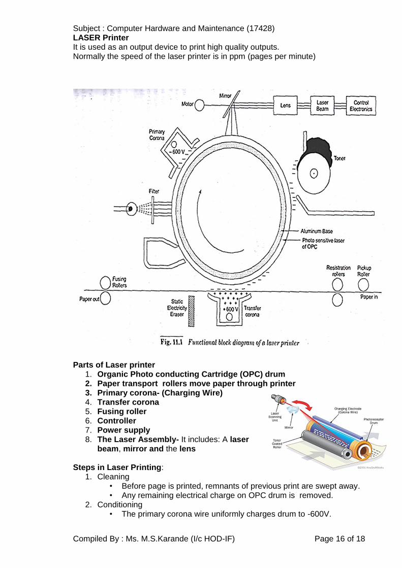
LASER Printer It is used as an output device to print high quality outputs. Normally the speed of the laser printer is in ppm (pages per minute)
Parts of Laser printer
1. Organic Photo conducting Cartridge (OPC) drum 2. Paper transport rollers move paper through printer 3. Primary corona- (Charging Wire) 4. Transfer corona 5. Fusing roller 6. Controller 7. Power supply 8. The Laser Assembly- It includes: A laser
beam, mirror and the lens Steps in Laser Printing:
1. Cleaning • Before page is printed, remnants of previous print are swept away. • Any remaining electrical charge on OPC drum is removed.
2. Conditioning • The primary corona wire uniformly charges drum to -600V.

Subject : Computer Hardware and Maintenance (17428)
Compiled By : Ms. M.S.Karande (I/c HOD-IF) Page 17 of 18
3. Writing • Where laser beam contacts drum, the charge is reduced to
-100V from -600V • Image of page is created on drum
4. Developing (Deposition of Toner) • The particles of toner in toner cartridge are attracted to the areas of drum
(-100V) exposed by laser creating print image on drum 5. Transferring of Image
• Sheet of paper at registration roller is given a positive charge (+600V) • Negatively charged toner on drum is attracted onto positively charged
paper(+600V) • Image is transferred to paper.
6. Fusing of Image • Fusing rollers apply heat and pressure to toner • Toner melts and permanently bonds to paper
Block Diagram of Laser Printer
Advantages of Laser Printer: 1. It is a non impact printer. 2. It is not noisy. 3. Printing speed is fast. 4. Printing quality is very good. Disadvantages
1. Costly as compared to other printers 2. Multi-part stationary cannot be used 3. Experts are required for maintenance

Subject : Computer Hardware and Maintenance (17428)
Compiled By : Ms. M.S.Karande (I/c HOD-IF) Page 18 of 18
Comparison between Dot-Matrix, InkJet and laser
Sr. No
Features Dot matrix InkJet Laser
01 Print mechanism
Impact Non-Impact Non-Impact
02 Print Quality Good Better Best
03 Cost Low Moderate High
04 Noise Generated
Yes No No
05 Speed Low High Good
06 Maintenance required
High Low Low from experts only
07 Support color printing
No Yes Yes
MSBTE Questions 1. Write the working principle of mechanical key switch with neat diagram.(4M)(W-14)
2. Define the terms TWAIN, and OCR with reference to scanner
3. With neat diagram explain the working principle of flat bed scanner (4M)(W-14)
4. State any four printer characteristics.(2M)(S-14)
5. Enlist the types of key switches(2M)(S-14)
6. What is modem? Explain working of external modem with suitable diagram of Modem
(4M)(S-14)
7. Explain the working of optical mouse.(4M)(S-14)
8. With the block diagram, explain the working of dot matrix printer(8M)(S-14)
9. List any four advantages of Laser Printer over Dot Matrix printer.(4M)(W-14)
10. Give any four disadvantages of Ink-jet Printer.(2M)(W-14)
11. List any four advantages of optical mouse.(4M)(W-14).
12. Draw block diagram of Internal Modem and explain working of each block.(8M)(W-
14).
13. List any two types of mouse with their features. (2M W-15)
14. List any four types of key switches of keyboard(2M W-15)
15. List with meaning any four specification of Dot Matrix Printer.(4M W-15).
16. Draw the block diagram of optical mouse. Also list any four advantages of optical
mouse.(4M W-15)
22. Draw and explain block diagram of an internal modem.(4M W-15).
23. Explain with block diagram the working of flat-bed scanner.(8M W-15)
24. Write four types of key switches used in keyboard.(2M S-15)
25. Write two advantages and two disadvantages of Opto-mechanical mouse.(2M S-15).
26. Draw and explain the block diagram of external modem(4M S-15)
27. Draw and explain the Block diagram flat bed scanner(4M S-15)
28. Write any four important characteristics of Dot Matrix Printers.(4M S-15).
29. Draw and explain the Laser Printer block diagram and mention any two
important specifications.(8M W-15)