subject : scada the channel rte - uk.codra.net · manager at rte. “the link is controlled on...
TRANSCRIPT
The IFA 2000 project
RTE: Operator of
the French Power
Distribution Network
in France.
RTE was created in the
year 2000 to manage
electrical grid networks.
Its mission is to carry elec-
tricity across the power
grid linking power gener-
ation sites to consumption
centers. It is a real control
point for both monitoring
and supervising the grid.
RTE in north-eastern
France covers all or part
of the Nord-Pas de Cal-
ais, Picardie, and Cham-
pagne-Ardenne regions.
This grid is interconnected
Panorama crosses the Channel
Profile
• Subject : ScADA
• Process : electrical networks Management
• client : National Grid rte
• Date : 2008
• Installed based : - Panorama e2
- Panorama P2
- 2 redundant servers - SNMP Protocol - Windows Nt - Windows XP pro - tablet Pc
aims
Supervise the IFA 2000 link.
Improve the ScADA system, and ensure its longevity.
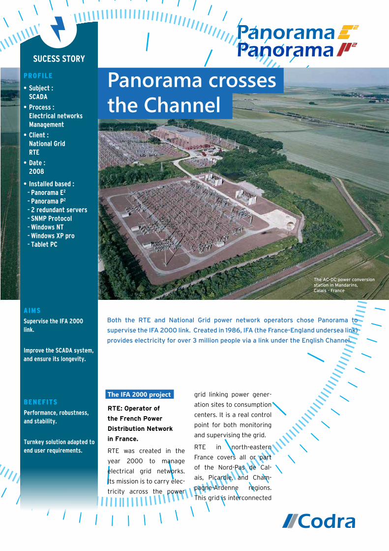
The AC-DC power conversion station in Mandarins,Calais - France
Both the RTE and National Grid power network operators chose Panorama to
supervise the IFA 2000 link. Created in 1986, IFA (the France-England undersea link)
provides electricity for over 3 million people via a link under the English Channel.
SuceSS Story
Benefits
Performance, robustness, and stability.
turnkey solution adapted to end user requirements.

to six countries, which in-
cludes e IFA 2000 link to
the United Kingdom. The
grid represents 500 billion
kW h of the French grid,
and consists of 100,000
km of high voltage lines.
Nevertheless, in the com-
ing years RTE is committed
to installing underground
connections to replace
certain overhead lines in
protected and urban are-
as.RTE has obtained both
ISO 14001 environmental
certification and ISO 9001
quality certification.
The IFA 2000 project :
Connecting France
and England
Created in 1986, IFA 2000
is a sub-sea link between
England and the rest of
Europe via France. The
project provides electrici-
ty to over 3
million peo-
ple and de-
livers 2000
megawatts
of energy. In
2002, RTE
decided to
both renew
its equip-
ment and replace obso-
lescent devices. The call
for tenders, awarded to
Cap Gemini, involved two
stages. The first stage, be-
gun in 2002, automated
exchanges across the link.
The second stage, in 2004,
renewed all the equip-
ment. The Panorama E2
Supervisory Control and
Data Acquisition. (SCADA)
software was selected to
manage the link. It took
18 months to develop the
IFA 2000 application, and
acceptance testing at the
plant began in late 2006.
To address changing re-
quirements, Cap Gemini
deployed a new application
which ran in controlled
mode between February
and June 2007. Final ac-
ceptance was approved in
August 2007.
The IFA 2000 project in-
volves several sites both in
France and England. The
control room
to manage
the system
is located
in Lomme,
a town
near Lille
in northern
France. Two
w o r k s t a -
tions have been installed
to manage the link in Man-
darin, near Calais (France)
and Sellindge (UK). “Via
the remote workstation,
we can for example change
the operations or transfer
program from either side
of the Channel,” says Mr.
Alain Lozon, the IFA Link
Regional dispatching in Lomme - France
From industrial SCADA to a global information system
SuceSS Story
Why choose Panorama ?
Flexible system.
24h/24 accessibility.
Real time display.

Manager at RTE. “The link
is controlled on alternate
weeks by the French and
the English teams. Con-
trol activities are synchro-
nized between the French
and English teams every
Thursday, but also when-
ever a problem arises. This
rotation enables both units
to keep their skills up to
date.”
The hardware and
software architecture
of the IFA 2000 link
Before the Panorama
SCADA application was de-
ployed, the application ran
under a Linux system. RTE
launched a call for tenders
in order to upgrade its ag-
ing technologies, improve
the SCADA system, and
ensure its longevity. Cap
Gemini chose Panorama E2
instead of a custom de-
velopment project, which
would have cost 3.6 times
as much in programming
costs. Panorama E2 is a
ready-touse tool with a
much shorter develop-
ment cycle and offering
basic functions adapted
to end user requirements.
Although RTE was ini-
tially reluctant to use a
Windows based soltion,
the company is extremely
satisfied with their SCADA
solution. The company
cited improvements in
performance, robustness,
and stability. Furthermore,
the setup time was rela-
tively short for a project
of this size. RTE opted
for a client/server soft-
ware architecture based
on Panorama E2 which
both controls the system
and performs data acqui-
sition. Custom develop-
ment is seamlessly inte-
grated into the Panorama
Architecture. Each PCP
workstation manages five
major functions:
• The Human Machine
Interface function super-
vises the IFA link and the
two-terminal networks,
and enables program-
ming,
• The Supervisor function
controls and transmits
operating instructions,
limits, urgent transit re-
quests, etc.
• The Configurator function,
• The Pre-programmer
function,
• The External Information
System Exchange Man-
agement function sends
An operator workstation: Controlling two-terminal networks
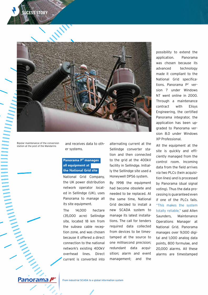
Bipolar maintenance of the conversion station at the post of the Mandarins
and receives data to oth-
er systems.
Panorama P² managesall equipment at the National Grid site
National Grid Company,
the UK power distribution
network operator locat-
ed in Sellindge (UK), uses
Panorama to manage all
its site equipment.
The 14,000 hectare
(35,000 acre) Sellindge
site, located 18 km from
the subsea cable recep-
tion zone, and was chosen
because it offered a direct
connection to the national
network’s existing 400kV
overhead lines. Direct
current is converted into
alternating current at the
Sellindge converter sta-
tion and then connected
to the grid at the 400kV
facility in Sellindge. Initial-
ly the Sellindge site used a
Honeywell DPS6 system.
By 1998 the equipment
had become obsolete and
needed to be replaced. At
the same time, National
Grid decided to install a
new SCADA system to
manage its latest installa-
tions. The call for tenders
required data collected
from devices to be times-
tamped at the source to
one millisecond precision;
redundant data acqui-
sition; alarm and event
management; and the
possibility to extend the
application. Panorama
was chosen because its
advanced technology
made it compliant to the
National Grid specifica-
tions. Panorama P2 ver-
sion 7 under Windows
NT went online in 2000.
Through a maintenance
contract with Elisys
Engineering, the certified
Panorama integrator, the
application has been up-
graded to Panorama ver-
sion 8.0 under Windows
XP Professional.
All the equipment at the
site is quickly and effi-
ciently managed from the
control room. Incoming
data from the field arrives
via two PLCs (twin acquisi-
tion lines) and is processed
by Panorama (dual signal
voting). Thus the data pro-
cessing is guaranteed even
if one of the PLCs fails.
“This makes the system
totally reliable,” said Allen
Saunders, Maintenance
Operations Manager at
National Grid. Panorama
manages over 9,000 digi-
tal and 1,000 analog data
points, 800 formulae, and
20,000 alarms. All these
alarms are timestamped
SuceSS Story
From industrial SCADA to a global information system
at the source to one milli-
second precision. The net-
work application architec-
ture can be separated into
two parts, with two redun-
dant data acquisition serv-
ers and five workstations.
“We have total visibility of
the entire plant from any
workstation. Furthermore,
during maintenance oper-
ations such as a change
of equipment or a soft-
ware update, we can cut
off part of the network
while the rest remains ful-
ly operational,” said Allen
Saunders. The worksta-
tions provide a real-time
view of all types of infor-
mation: alarms, events,
and analog data such as
temperature, pressure,
or volume. Operators can
instantaneously view and
validate the information,
as well as analyze the ap-
plication’s historical data.
Since 2006 the National
Grid site uses an 802.11
wireless network and Tab-
let PCs. Now the SCADA
application is accessible
from anywhere at the site,
without going through
the control room. “This
is a great advantage for
everyone here. The sys-
tem is flexible and availa-
ble 24 hours a day. Thus
we only need two people
on call at a site, and one at
home in case of emergen-
cy,” said Gary Lima-Napier,
the founder of Elisys Engi-
neering.
The Panorama-certified
integrator has also added
a bilingual email function
as well as a VoIP emergen-
cy call system.
Focus on...
High voltage lines are the
main lines in the electrical
power grid. They may be
KeY fiGures
The RTE Northeast network :
• 9200 km of overhead power lines
• 200 km of sub-sea power lines
• 220 transformation units
• 4 cross-border interconnections
• 10% of the French national network
IFA 2000
• Total length: 70 km, including 45 km under the Channel
• High voltage direct current
• 2000 megawatts
ELISYS ENGINEERING
Elisys Engineering was founded in 2003 mainly to assist National Grid in de-
ploying Panorama.
The company’s qualified staff receives training from Codra in France. Today it
is the leading English Panorama Certified Integrator (PCI).
Elisys Engineering develops turnkey applications, manages maintenance and
updates, and provides quality technical support.
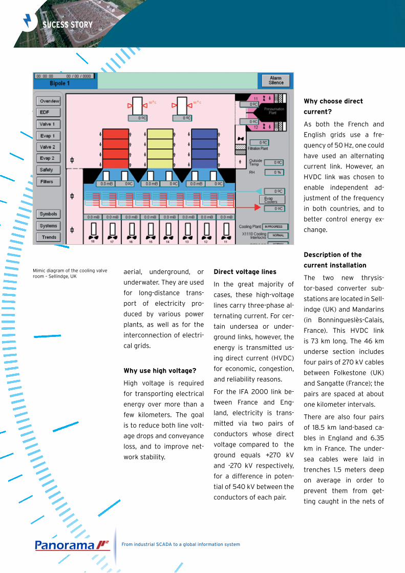
Mimic diagram of the cooling valve room – Sellindge, UK
aerial, underground, or
underwater. They are used
for long-distance trans-
port of electricity pro-
duced by various power
plants, as well as for the
interconnection of electri-
cal grids.
Why use high voltage?
High voltage is required
for transporting electrical
energy over more than a
few kilometers. The goal
is to reduce both line volt-
age drops and conveyance
loss, and to improve net-
work stability.
Direct voltage lines
In the great majority of
cases, these high-voltage
lines carry three-phase al-
ternating current. For cer-
tain undersea or under-
ground links, however, the
energy is transmitted us-
ing direct current (HVDC)
for economic, congestion,
and reliability reasons.
For the IFA 2000 link be-
tween France and Eng-
land, electricity is trans-
mitted via two pairs of
conductors whose direct
voltage compared to the
ground equals +270 kV
and -270 kV respectively,
for a difference in poten-
tial of 540 kV between the
conductors of each pair.
Why choose direct
current?
As both the French and
English grids use a fre-
quency of 50 Hz, one could
have used an alternating
current link. However, an
HVDC link was chosen to
enable independent ad-
justment of the frequency
in both countries, and to
better control energy ex-
change.
Description of the
current installation
The two new thrysis-
tor-based converter sub-
stations are located in Sell-
indge (UK) and Mandarins
(in Bonningueslès-Calais,
France). This HVDC link
is 73 km long. The 46 km
underse section includes
four pairs of 270 kV cables
between Folkestone (UK)
and Sangatte (France); the
pairs are spaced at about
one kilometer intervals.
There are also four pairs
of 18.5 km land-based ca-
bles in England and 6.35
km in France. The under-
sea cables were laid in
trenches 1.5 meters deep
on average in order to
prevent them from get-
ting caught in the nets of
From industrial SCADA to a global information system
SuceSS Story
trawlers, which occurred
frequently with the previ-
ous installation and result-
ed in an availability rate
rarely above 50%.
Until 2001 the link was
used exclusively by EDF.
Since the opening of the
electricity market to com-
petition on April 1, 2001,
the link has been operat-
ed jointly by the French
company RTE (Réseau de
transport d’électricité)
and its British counterpart
National Grid.
BIDDING SYSTEm TO mANAGE POWER ACCESS
In order to guarantee the strictly equitable, nondiscriminatory assignment of
rights to share the link among all market players (traders, suppliers, produ-
cers, etc.), RTE and NGC set up a coordinated bidding system on April 1, 2001
in order to ensure the fluidity and transparency of electrical exchanges, while
providing a secure energy supply.
In both directions (France-England and England-France), various types of pro-
ducts are open to bidding according to different periods: annual, quarterly,
monthly, daily, and (since 2004) half-yearly and week-ends. Bidding results
(made anonymously) are published daily on the RTE Web site. The «use it or
lose it» principle is applied: capacity not used by customers is reassigned.
Revenue from bids enables operators to cover their operating costs and repay
the cost of the link: RTE’s power distribution rates do not include access to
IFA, which has its own financial accounting.
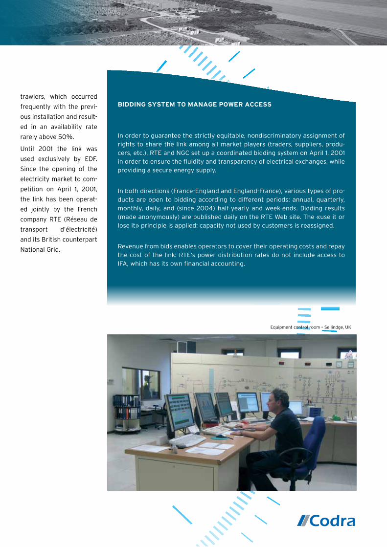
Equipment control room – Sellindge, UK

Outlook
Studies are underway to
further improve the link’s
availability and eventually
to increase the capacity
of its interconnection by
1,000 MW. However, it is
difficult to predict both
the future of these ex-
changes and the ideal link
dimensioning, in light of
the evolving energy de-
mands in Europe.
The information in this document is provided for information only and isnot binding. Codra reserves the right to change the document at any timewithout warning. All brands are the property of their respective owners.© 2008-2013
Codra Software Limited
960, Capability Green - Luton - Bedfordshire - LU1 3PE - UK
Tel : + 44 (0)1582 635040 - Fax : + 44 (0)1582 635001
E-Mail : [email protected] - http://uk.codra.net
From industrial SCADA to a global information system
SuceSS Story
architecture
• 2 redundant servers in the A & B equipment rooms
• 5 workstations (Bipole 1, Bipole 2, security workstation, alarm workstation, development workstation)
• SNMP protocol
• 2 Tablet PCs
• 24 wireless access terminals without disconnection
harDWare architecture
• 1 supervision server
• 3 workstations
• 1 firewall
• 2 printers
• 1 router for communicating with the printers
Viewing the system over the wireless network via a Tablet PC,Sellindge, UK