subject: standard operating - cast- · pdf filesubject: standard operating procedures for...
TRANSCRIPT

Subject: STANDARD OPERATINGPROCEDURES FOR FLIGHT DECKCREWMEMBERS
Date: 8/10/00Initiated By: AFS-210
AC No: 120-71
1. PURPOSE. Standard operating procedures (SOPs) are universally recognized as basic to safeaviation operations. Effective crew coordination and crew performance, two central concepts ofcrew resource management (CRM), depend upon the crew’s having a shared mental model ofeach task. That mental model, in turn, is founded on SOPs. This advisory circular (AC) presentsbackground, basic concepts, and philosophy in respect to SOPs. It emphasizes that SOPs shouldbe clear, comprehensive, and readily available in the manuals used by flight deck crewmembers.This AC is designed to provide advice and recommendations about development, implementation,and updating of SOPs. Many important topics that should be addressed in SOPs are provided inAppendix 1, Standard Operating Procedures Template. Stabilized Approach, characterized by aconstant-angle, constant-rate of descent ending near the touchdown point, where the landingmaneuver begins, is among the SOPs specifically identified in this AC, and is described inAppendix 2, Stabilized Approach: Concepts and Terms. These and the other Appendicesfollowing them represent a baseline and a starting point. Start-up certificate holders and existingcertificate holders should refer to the Template in Appendix 1, to Stabilized Approach inAppendix 2, and to the other Appendices to this AC in developing comprehensive SOPs for use intraining programs and in manuals used by their flight deck crewmembers.
2. SCOPE. Appendix 1 consolidates many topics viewed by operators and by the FAA asimportant, to be addressed as SOPs in air carrier training programs and in the manuals used by aircarrier flight deck crewmembers. This AC does not list every important SOP topic or dictateexactly how each topic should be addressed by a certificate holder. Instead, this AC offers abaseline of topics, to be used as a reference. In practice, each certificate holder’s manuals andtraining programs are unique. Each certificate holder could omit certain topics shown in thetemplate when they do not apply, and, on the other hand, could add other topics not shown in thetemplate when they do apply. This AC contains guidance intended for use primarily by Title 14 ofthe Code of Federal Regulations (14 CFR) part 119 certificate holders authorized to conductoperations under part 121. But operators of aircraft under 14 CFR parts 135, 125, 91, and othersshould also find this guidance useful.
3. RELATED REGULATIONS. 14 CFR part 121, sections 121.133, 121.141, 121.401;14 CFR part 125, section 125.287; 14 CFR part 135, section 135.293.

AC 120-71 8/10/00
Par 4Page 2
4. RELATED READING MATERIAL.
a. AC 120-51 as amended, Crew Resource Management Training(http://www.faa.gov/avr/afs/acs/120-51C.PDF).
b. AC 120-48, Communication and Coordination between Flight Crewmembers and FlightAttendants.
c. AC 120-54, Advanced Qualification Program.
d. AC 121-32, Dispatch Resource Management Training.
NOTE: AC’s may be obtained by mail from:
U.S. Department of Transportation Subsequent Distribution Office, SVC-121.23 Ardmore East Business Center 3341 Q 75th Ave. Landover, MD 20785
e. Controlled Flight into Terrain Education and Training Aid (Flight Safety Foundation,
ICAO, and Federal Aviation Administration (FAA), http://www.faa.gov/avr/afs/train.htm).
f. Flight Safety Digest, Nov. 98 – Feb. 99 (Flight Safety Foundation).
g. Approach-and-landing Risk Awareness Tool, as revised (Flight Safety Foundation,http://www.flightsafety.org/pdf/alar_risk_tool.pdf).
h. CFIT Checklist, as revised (Flight Safety Foundation,http://www.flightsafety.org/pdf/cfit_check.pdf).
i. Guidelines for Situation Awareness Training (Naval Air Warfare Center Training SystemsDivision, the FAA AAR-100, and the University of Central Florida Department of Psychology,http://www.faa.gov/avr/afs/train.htm).
j. Human Performance Considerations in the Use and Design of Aircraft Checklists (FAA,http://www.faa.gov/avr/afs/train.htm).
k. Flight Standardization Board Reports (FAA, http://www.opspecs.com/FinalFSBRs/).
5. BACKGROUND.
a. Many aviation safety organizations including the FAA have recently reaffirmed theimportance of SOPs.

8/10/00 AC 120-71
Par 5 Page 3
b. For many years the National Transportation Safety Board (NTSB) has identifieddeficiencies in standard operating procedures as contributing causal factors in aviation accidents.Among the most commonly cited deficiencies involving flightcrews has been their non-compliance with established procedures; another has been the non-existence of establishedprocedures in some manuals used by flightcrews.
c. The International Civil Aviation Organization (ICAO) has also recognized the importanceof SOPs for safe flight operations. Recent amendments to ICAO Annex 6 establish that eachmember state should require that SOPs for each phase of flight be contained in the operationsmanual used by pilots.
d. Non-government aviation safety organizations such as Flight Safety Foundation,Alexandria, Virginia, have concluded that airlines perform with higher levels of safety when theyestablish and adhere to adequate SOPs.
e. In 1997 the FAA joined with representatives from the National Aeronautics and SpaceAdministration (NASA) and from a broad cross-section of aviation organizations to form theCommercial Aviation Safety Team (CAST). Chartered by the White House to reduce thecommercial aviation accident rate by 80 percent in 10 years, this Team chose controlled flightinto terrain (CFIT) as one of the first major aviation hazards to be addressed in meeting thischallenge. The Team used a data-driven approach to identify interventions with the highestpossible safety leverage, and to develop a comprehensive agenda to implement thoseinterventions.
f. In its study of CFIT accidents, a CAST analysis team including the FAA corroborated thefindings of the NTSB, ICAO, and other groups. Almost 50 percent of the 107 CFITinterventions identified by that analysis team related to the flightcrew’s failure to adhere to SOPsor the certificate holder’s failure to establish adequate SOPs. Subsequent CAST teamsconfirmed their analysis further.
g. This AC is in large part the final report and end-product of one of the CAST sub-teams, agroup comprised of subject matter experts in aviation human factors, in airline operations, and inflightcrew training.
6. THE MISSION OF SOPs. To achieve consistently safe flight operations through adherenceto SOPs that are clear, comprehensive, and readily available to flight crewmembers.
7. APPLYING THE SOPs TEMPLATE AND OTHER APPENDICES. Generally, eachSOP topic identified in the template (following as Appendix 1) is important and should beaddressed in some manner by the certificate holder, if applicable. Stabilized Approach(Appendix 2) is a particularly important SOP. Other important SOPs, such as those associatedwith special operating authority or with new technology, are not shown in the template, butshould be addressed as well, when applicable. Because each certificate holder’s operation isunique, developing the specific manner in which SOPs are addressed is the task of the certificateholder. Topics expanded and illustrated in the Appendices are for example only, and representrenditions of SOPs known to be effective. No requirement is implied or intended to change

AC 120-71 8/10/00
Par 7Page 4
existing SOPs based solely on these examples. An SOP topic shown in the Appendices may beaddressed in detail, including text and diagrams, or in very simple terms. For example, an SOPmay be addressed in a simple statement such as: “ABC Airlines does not conduct Category 3approaches.”
8. KEY FEATURES OF EFFECTIVE SOPs.
a. Many experts agree that implementation of any procedure as an SOP is most effective if:
(1) The procedure is appropriate to the situation.
(2) The procedure is practical to use.
(3) Crewmembers understand the reasons for the procedure.
(4) Pilot Flying (PF), Pilot Not Flying (PNF), and Flight Engineer duties are clearlydelineated.
(5) Effective training is conducted.
(6) The attitudes shown by instructors, check airmen, and managers all reinforce theneed for the procedure.
b. If all elements (above) are not consistently implemented, flightcrews too easily becomeparticipants in an undesirable double standard condoned by instructors, check airmen, andmanagers. Flightcrews may end up doing things one way to satisfy training requirements andcheckrides, but doing them another way in “real life” during line operations. When a doublestandard does appear in this way, it should be considered a red flag that a published SOP may notbe practical or effective for some reason. That SOP should be reviewed and perhaps changed.
9. THE IMPORTANCE OF UNDERSTANDING THE REASONS FOR AN SOP.
a. Effective Feedback. When flightcrew members understand the underlying reasons for anSOP they are better prepared and more eager to offer effective feedback for improvements. Thecertificate holder, in turn, benefits from more competent feedback in revising existing SOPs andin developing new SOPs. Those benefits include safety, efficiency, and employee morale.
b. Troubleshooting. When flightcrew members understand the underlying reasons for anSOP, they are generally better prepared to handle a related in-flight problem that may not beexplicitly or completely addressed in their operating manuals.
10. COLLABORATING FOR EFFECTIVE SOPs.
a. In general, effective SOPs are the product of healthy collaboration among managers andflight operations people, including flightcrews. A safety culture promoting continuous feedbackfrom flightcrews and others, and continuous revision by the collaborators distinguishes effectiveSOPs at airlines of all sizes and ages.

8/10/00 AC 120-71
Par 10 Page 5 (and 6)
b. New operators, operators adding a new aircraft fleet, or operators retiring one aircraft fleetfor another must be especially diligent in developing SOPs. Collaborators with applicableexperience may be more difficult to bring together in those instances.
c. For a startup certificate holder, this AC and its Appendices should be especially valuabletools in developing SOPs. The developers should pay close attention to the approved airplaneflight manual (AFM), to AFM revisions and operations bulletins issued by the manufacturer, andto the applicable Flight Standardization Board (FSB) report issued by the FAA. Desirablepartners in the collaboration would certainly include representatives of the airplanemanufacturer, pilots having previous experience with the airplane or with the kind of operationsplanned by the operator, and representatives from the FAA, including the principal operationsinspector (POI), members of the Certificate Management Team, and members of theCertification, Standardization, and Evaluation Team (CSET). It is especially important for a newoperator to maintain a periodic review process that includes line flightcrews. Together,managers and flightcrews are able to review the effectiveness of SOPs and to reach validconclusions for revisions. The review process will be meaningful and effective when managerspromote prompt implementation of revisions to SOPs when necessary.
d. An existing certificate holder introducing a new airplane fleet should also collaborateusing the best resources available, including the AFM, operations bulletins, and the FSB report.Experience has shown that representatives of the airplane manufacturer, managers, check airmen,instructors, and line pilots work well together as a team to develop effective SOPs. A trial periodmight be implemented, followed by feedback and revision, in which SOPs are improved. Bybeing part of an iterative process for changes in SOPs, the end user, the flight crewmember, isgenerally inclined to accept the validity of changes and to implement them readily.
e. Long-established operators should be careful not to assume too readily that they canoperate an airplane recently added to the fleet in the same, standard way as older types ormodels. Managers, check airmen, and instructors should collaborate using the best resourcesavailable, including the AFM, operations bulletins, and the FSB report to ensure that SOPsdeveloped or adapted for a new airplane are in fact effective for that aircraft, and are notinappropriate carryovers.
11. SUMMARY. Safety in commercial aviation continues to depend on good crewperformance. Good crew performance, in turn, is founded on standard operating procedures thatare clear, comprehensive, and readily available to the flightcrew. This AC provides an SOPstemplate and many other useful references in developing SOPs. Development of SOPs is mosteffective when done by collaboration, using the best resources available including the end-usersthemselves, the flightcrews. Once developed, effective SOPs should be continually reviewedand renewed.
/s/L. Nicholas LaceyDirector, Flight Standards Service

8/10/00 AC 120-71
Page i (and ii)
NOTES ON APPENDICES
The following appendices contain examples of standard operating procedures (SOPs) that areidentical to or similar to some SOPs currently in use. Those examples do not represent a rigidFAA view of best practices, which may vary among fleets and among certificate holders, andmay change over time.
Some of the examples may be readily adapted to a certificate holder’s flightcrew training andoperating manuals for various airplane fleets. Others may apply to a certain airplane fleet andmay not be adaptable apart from that fleet.
In some cases a term shown in an Appendix is a term used by a certificate holder, not theequivalent term used by the FAA. Example: Where the FAA would use the term “height abovetouchdown,” or HAT, the example shows that the certificate holder has used the term “abovefield elevation,” or (AFE).

8/10/00 AC 120-71Appendix 1
Page 1
APPENDIX 1
STANDARD OPERATING PROCEDURES TEMPLATE
A manual or section in a manual serving as the flightcrew’s guide to standard operatingprocedures (SOPs) may double as a training guide. The content should be clear andcomprehensive, without necessarily being lengthy. No template could include every topic thatmight apply unless it were constantly revised. Many topics involving special operating authorityor new technology are absent from this template, among them ETOPS, PRM, SMGS, RNP, andmany others.
The following are nevertheless viewed by industry and FAA alike as examples of topics thatconstitute a useful template for developing comprehensive, effective SOPs:
• Captain’s authority • Use of automation The operator’s automation philosophy
Specific guidance in selection of appropriate levels of automation Autopilot/flight director mode control inputs
Flight management systems inputs • Checklist philosophy Policies and procedures (Who calls for; who reads; who does) Format and terminology Type of checklist Challenge-Do-Verify Do-Verify Walk-arounds • Checklists Safety check -- power on Originating/receiving Before start After start
Before taxi Before take-off After take-off Climb check Cruise check Preliminary landing Landing After landing Parking and securing Emergency procedures Non-normal/abnormal procedures
AC 120-71 8/10/00Appendix 1
Page 2
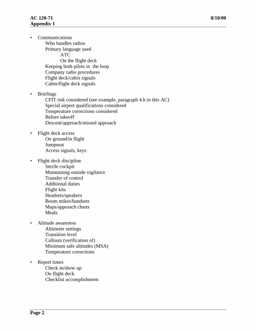
• Communications Who handles radios Primary language used ATC On the flight deck Keeping both pilots in the loop Company radio procedures Flight deck/cabin signals Cabin/flight deck signals • Briefings
CFIT risk considered (see example, paragraph 4.h in this AC) Special airport qualifications considered Temperature corrections considered Before takeoff Descent/approach/missed approach • Flight deck access On ground/in flight Jumpseat Access signals, keys • Flight deck discipline Sterile cockpit Maintaining outside vigilance
Transfer of control Additional duties Flight kits Headsets/speakers Boom mikes/handsets Maps/approach charts Meals • Altitude awareness Altimeter settings Transition level Callouts (verification of) Minimum safe altitudes (MSA) Temperature corrections • Report times Check in/show up On flight deck Checklist accomplishment

8/10/00 AC 120-71Appendix 1
Page 3
• Maintenance procedures Logbooks/previous write-ups Open write-ups Notification to maintenance of write-ups Minimum equipment list (MEL) Where it is accessible Configuration Deviation List (CDL) Crew coordination in ground de-icing • Flight plans/dispatch procedures VFR/IFR Icing considerations Fuel loads Weather package Where weather package is available Departure procedure climb gradient analysis • Boarding passengers/cargo Carry-on baggage Exit row seating Hazardous materials Prisoners/escorted persons Guns onboard Count/load • Pushback/powerback • Taxiing Single engine All engines On ice or snow Prevention of runway incursion • Crew resource management (CRM) Crew briefings Flight attendants Flightcrew • Weight & balance/cargo loading Who is responsible for loading cargo, and securing cargo
Who prepares the weight & balance data form; who checks it Copy to crew • Flight deck/cabin crew interchange Boarding Ready to taxi Cabin emergency Prior to take-off/landing

AC 120-71 8/10/00Appendix 1
Page 4
• Take-off Who conducts it Briefing, IFR/VFR Reduced power procedures Tailwind, runway clutter Intersections/land and hold short procedures (LAHSO) Noise abatement procedures Special departure procedures Flight directors Use of: Yes/No Callouts
Clean up Loss of engine
Rejected takeoff After V1 Actions/callouts
Flap settings Normal Nonstandard and reason for Crosswind Close-in turns
• Climb
SpeedsConfiguration
Confirm compliance with climb gradient required in departure procedure Confirm appropriate cold temperature corrections made
• Cruise altitude selection Speeds/weights • Position reports ATC Company
• Emergency descents • Holding procedures
Procedures for diversion to alternate
• Normal descentsPlanning beginning of descent pointRisk assessment and briefing (see example, paragraph 4.g in this AC)
Speedbrakes: Yes/No Flaps/gear use

8/10/00 AC 120-71Appendix 1
Page 5 (and 6)
Icing considerationsConvective activity
• Ground proximity warning system (GPWS or TAWs) Escape maneuver • TCAS • Windshear
Avoidance of likely encounters Recognition Recovery / escape maneuver • Approach philosophy Precision approaches preferred Stabilized approaches standard
Use of navigation aids Flight management system (FMS)/autopilot Use, and when to discontinue use Approach gates Limits for stabilized approaches Use of radio altimeter Go-arounds: Plan to go around; change plan to land when visual, if stabilized • Individual approach type All types, including engine-out • For each type of approach Profile Flap/gear extension Callouts Procedures • Go-around / missed approach When stabilized approach gates are missed (see example, Appendix 4) Procedure Callouts Clean-up profile • Landing
Actions and calloutsConfiguration for conditions
Visual approachLow visibilityContaminated runway
Close-in turnsCrosswindRejectedTransfer of control after first officer landing

8/10/00 AC 120-71Appendix 2
Page 1
APPENDIX 2
STABILIZED APPROACH: CONCEPTS AND TERMS
A stabilized approach is one of the key features of safe approaches and landings in air carrieroperations, especially those involving transport category airplanes.
A stabilized approach is characterized by a constant-angle, constant-rate of descent approachprofile ending near the touchdown point, where the landing maneuver begins. A stabilizedapproach is the safest profile in all but special cases, in which another profile may be required byunusual conditions.
All appropriate briefings and checklists should be accomplished before 1000’ height abovetouchdown (HAT) in instrument meteorological conditions (IMC), and before 500’ HAT invisual meteorological conditions (VMC)
Flight should be stabilized by 1000’ height above touchdown (HAT) in instrumentmeteorological conditions (IMC), and by 500’ HAT in visual meteorological conditions (VMC).
An approach is stabilized when all of the following criteria are maintained from 1000 HAT (or500 HAT in VMC) to landing in the touchdown zone:
The airplane is on the correct1 track.
The airplane is in the proper landing configuration.
After glide path intercept, or after the FAF, or after the derived fly-off point (perJeppesen) the pilot flying requires no more than normal bracketing corrections2 tomaintain the correct track and desired profile (3° descent angle, nominal) to landingwithin the touchdown zone. Level-off below 1000’ HAT is not recommended.
The airplane speed is within the acceptable range specified in the approved operatingmanual used by the pilot.
The rate of descent is no greater than 1000 fpm.• If an expected rate of descent greater than 1000 fpm is planned, a special approach
briefing should be performed.• If an unexpected, sustained rate of descent greater than 1000 fpm is encountered
during the approach, a missed approach should be performed. A second approachmay be attempted after a special approach briefing, if conditions permit.
Power setting is appropriate for the landing configuration selected, and is within thepermissible power range for approach specified in the approved operating manual usedby the pilot.

AC 120-71 8/10/00Appendix 2
Page 2
APPENDIX 2 (con’t)
When no vertical guidance is provided: Vertical guidance may be provided to the pilot by wayof an electronic glideslope, a computed descent path displayed on the pilot’s navigation display, orother electronic means. On approaches for which no vertical guidance is provided, the flightcrewshould plan, execute, and monitor the approach with special care, taking into account traffic andwind conditions. To assure vertical clearance and situation awareness, the pilot not flying shouldannounce crossing altitudes as published fixes and other points selected by the flightcrew arepassed. The pilot flying should promptly adjust descent angle as appropriate. A constant-angle,constant-rate descent profile ending at the touchdown point is the safest profile in all but specialcases.
Visual contact. Upon establishing visual contact with the runway or appropriate runwaylights or markings, the pilot should be able to continue to a safe landing using normalbracketing corrections, or, if unable, should perform a missed approach.
No visual contact. The operator may develop procedures involving an approved, standardMDA buffer altitude or other approved procedures to assure that descent below MDA doesnot occur during the missed approach. If no visual contact is established approachingMDA or an approved MDA buffer altitude, or if the missed approach point is reached, thepilot should perform the published missed approach procedure. (OpSpec paragraph C073provides for special authorization under certain conditions to go below the MDA whileexecuting a missed approach.) Below 1000’ HAT, leveling off at MDA (or at some heightabove MDA) is not recommended, and a missed approach should be performed.
Note 1 : A correct track is one in which the correct localizer, radial, or other track guidance hasbeen set, tuned, and identified, and is being followed by the pilot. Criteria for following thecorrect track are discussed in FAA Advisory Circulars relating to Category II and Category IIIapproaches. Criteria for following track in operations apart for Category II and Category III areunder development.
Note 2 : Normal bracketing corrections relate to bank angle, rate of descent, and powermanagement. Recommended ranges are as follows (operating limitations in the approvedairplane flight manual must be observed, and may be more restrictive):
Bank angle Maximum bank angle permissible during approach is specified in the approved operatingmanual used by the pilot, and is generally not more than 30°; the maximum bank anglepermissible during landing may be considerably less than 30°, as specified in thatmanual.
Rate of descent ± 300 fpm deviation from target
Power management Permissible power range is specified in the approved operating manual used by the pilot
Overshoots Normal bracketing corrections occasionally involve momentary overshoots madenecessary by atmospheric conditions. Such overshoots are acceptable. Frequent orsustained overshoots caused by poor pilot technique are not normal bracketingcorrections.

8/10/00 AC 120-71Appendix 3
Page 1 (and 2)
APPENDIX 3
(examples)
ATC COMMUNICATIONSand
ALTITUDE AWARENESS
ATC Communications: SOPs should state who (PF, PNF, FE/SO) handles the radios for eachphase of flight, as follows:
PF makes input to aircraft/autopilot and/or verbally states clearances while PNF confirmsinput is what he/she read back to ATC.
Any confusion in the flight deck is immediately cleared up by requesting ATCconfirmation.
If any crewmember is off the flight deck, all ATC instructions are briefed upon his/herreturn. Or if any crewmember is off the flight deck all ATC instructions are writtendown until his/her return and then passed to that crewmember upon return. Similarly, if acrewmember is off ATC frequency (e.g., when making a PA announcement or whentalking on company frequency), , all ATC instructions are briefed upon his/her return.
Company policy should address use of speakers, headsets, boom mike and/or hand-heldmikes.
Altitude Awareness: SOPs should state the company policy on confirming assigned altitude.
Example: The PNF acknowledges ATC altitude clearance.If the aircraft is on the autopilot then the PF makes input into the autopilot/altitudealerter. PF points to the input while stating the assigned altitude as he/she understands it.The PNF then points to the input stating aloud what he/she understands the ATCclearance to be confirming that the input and clearance match.
If the aircraft is being hand-flown then the PNF makes the input into the AltitudeAlerter/autopilot, then points to the input and states clearance. PF then points to thealterter stating aloud what he/she understands the ATC clearance to be confirming thatthe alerter and clearance match.Example: If there is no altitude alerter in the aircraft then both pilots write down theclearance, confirm that they have the same altitude and then cross off the previouslyassigned altitude.

8/10/00 AC 120-71Appendix 4
Page 1 (and 2)
APPENDIX 4
(example)
NORMAL GO-AROUND -- ACTIONS and CALLOUTS
Callouts: shown in “BOLD TEXT” -- Actions: shown with bullets (••) in plain textPF PNFGo-around
“GO AROUND”• Press either GA switch“GO-AROUND POWER”• Verify thrust levers move to
GA power• Rotate towards 15° pitch
attitude, then follow flightdirector commands “FLAPS20”
• Verify GA annunciates
• Select flaps 20• Verify thrust levers move to
maintain 2,000 FPM climbrate
“POWER SET”Positive Rate ofClimb • Verify positive rate of climb
“GEAR UP”
• Execute publishedmissed approach orproceed as instructedby ATC
“POSITIVE RATE”
• Position gear lever UP• Advise ATC
• Monitor missed approachprocedures
At or above400’ AFE
“LNAV” or “HEADINGSELECT” • Select LNAV or HDG
SEL• Verify LNAV or HDG SEL
annunciatesClimbingthrough 1,000’AFE
“REF 80”
“FLAPS_____”(Retract flaps on flapretraction speed schedule)
• Set command airspeedcursor to VREF 30 + 80
• Select proper flapsetting, when requesting
At flapretraction
speed
“FLAPS UP, AFTERTAKEOFF CHECKLIST”
• Retract flaps• Accomplish checklist

8/10/00 AC 120-71Appendix 5
Page 1 (and 2)
APPENDIX 5
(example)
SINGLE ENGINE GO-AROUND -- ACTIONS and CALLOUTS
Callouts: shown in “BOLD TEXT” -- Actions: shown with bullets (••) in plain textPF PNF
Go-around “GO AROUND”• Press either GA switch“GO-AROUND POWER”• Advance thrust lever to GA
power• Rotate towards 10° pitch
attitude, then follow flightdirector commands
“FLAPS 5”
• Verify GA annuciates
• Verify GA power set
• Select flaps 5“POWER SET”
Positive Rate ofClimb • Verify positive rate of climb
“GEAR UP”
• Position gear lever UP• Advise ATC
•• Execute airport specific “Engine Failure Missed Approach,”published missed approach, or proceed as instructed by ATC, as
appropriateAt or above 400’AFE, or lower ifEngine Failureprocedurespecifies a turnprior to 400’AFE
“LNAV” or “HEADINGSELECT”
• Select LNAV or HDG SEL• Verify LNAV or HDG SEL
annunciates• Monitor missed approach
procedureClimbing through1,000’ AFE orobstructionclearance altitude(OCA), whicheveris higher
“REF 80”
“FLAPS_____”(Retract flaps on flap retractionspeed schedule)
• Set command airspeed cursor toVREF 30 + 80
• Select proper flap setting, whenrequested
At flapretraction
speed
“FLAPS UP”• Retract flaps
AtVREF 30 + 80
“MAXIMUM CONTINUOUSTHRUST AFTER TAKEOFFCHECKLIST”
• Press CON on TMSP• Set MCT“POWER SET”• Accomplish After Takeoff
Checklist

8/10/00 AC 120-71Appendix 6
Page 1 (and 2)
APPENDIX 6
(example)
SINGLE ENGINE VISUAL LANDING -- PROFILE

8/10/00 AC 120-71Appendix 7
Page 1 (and 2)
APPENDIX 7
(example)
SINGLE ENGINE ILS APPROACH -- ACTIONS and CALLOUTS
Callouts: shown in “BOLD TEXT” -- Actions: shown with bullets (••) in plain text
PF PNFInitialApproach
“FLAPS 1, REF 60”
“FLAPS 5, REF 40”
• Select flaps 1• Set command airspeed
cursor to VREF 30 + 60
• Select flaps 5• Set command airspeed
cursor to VREF 30 + 40•• Verify Nav radio tuned to appropriate ILS frequencyWhen Cleared
for theApproach
• Select APP mode• Verify LOC and G/S
annunciates white (armed) onADI
LOC Alive• Verify localizer indication
“LOCALIZER ALIVE”
LOC Capture •• Verify LOC annunciates green (captured) on ADIGS Alive
• Verify G/S indication
“GEAR DOWN, FLAPS 20,VREF 20 + 5, SINGLEENGINE LANDINGCHECKLIST”
“GLIDESLOPE ALIVE”
• Position gear lever DOWN• Select flaps 20• Set command airspeed
cursor to VREF 20 + 5• Complete Single Engine
Landing ChecklistGS Capture
“GLIDESLOPE CAPTURE”

8/10/00 AC 120-71Appendix 8
Page 1 (and 2)
APPENDIX 8
(example)
APPROACH PROFILE: LNAV, LOC, or LOC B/CRS

8/10/00 AC 120-71Appendix 9
Page 1
APPENDIX 9
(example)
LNAV, LOC, or LOC B/CRS APPROACH -- ACTIONS and CALLOUTS
Callouts: in “BOLD TEXT” -- Actions: with bullets (••) in plain textPF PNF
Initial Approach “FLAPS 1 REF 60”
“FLAPS 5, REF 40”
• Select flaps 1• Set command airspeed
cursor to VREF 30 + 60,if requested
• Select flaps 5• Set command airspeed
cursor to VREF 30 + 40,if requested
2-1/2 miles fromFAF
“GEAR DOWN, FLAPS 20,REF 20, LANDINGCHECKLIST” • Position gear lever
DOWN• Select flaps 20• Set command airspeed
cursor to VREF 30 +20, if requested
• Initiate LandingChecklist
½ mile prior to FAF “FLAPS 30, REF 5”
• Set/Request MDA or MDABuffer Altitude
• Select flaps 30• Set command airspeed
cursor to VREF 30 + 5,if requested
• Set altitude, ifrequested
•• Start timing, if appropriateAt FAF
• Select/Request V/S • Set V/S, if requested• Monitor descent
At 1,000’ AFE• Verify altitude• Stabilized approach
“1,000 ft.”

AC 120-71 8/10/00Appendix 9
Page 2
APPENDIX 9 (con’t)
Callouts: in “BOLD TEXT” -- Actions: with bullets (••) in plain textPF PNF
At 100’ aboveMDA (or MDAbuffer altitude)
• Verify altitude“100 ABOVE”• Divide time between
monitoring instrumentsand scanning outside forrunway environment
AT MDA (orMDA buffer) “SET MISSED
APPROACH ALTITUDE”• Execute missed approach
“MINIMUMS”
• Set missed approachaltitude
•• Call out appropriate visual cues
“LANDING”“RUNWAY IN SIGHT”
• Monitor speed and sinkrate
(Runwayenvironment IS in
sight)
•• See landing procedure
“GO-AROUND”
“MISSED APPROACHPOINT, NO CONTACT”
—or—(Runway
environmentNOT in sight or a
safe landing isNOT possible)
•• See go-around procedure

8/10/00 AC 120-71Appendix 10
Page 1 (and 2)
APPENDIX 10
(example)
ENGINE FAILURE AT or ABOVE V1 -- PROFILE
8/10/00 AC 120-71Appendix 11
Page 1
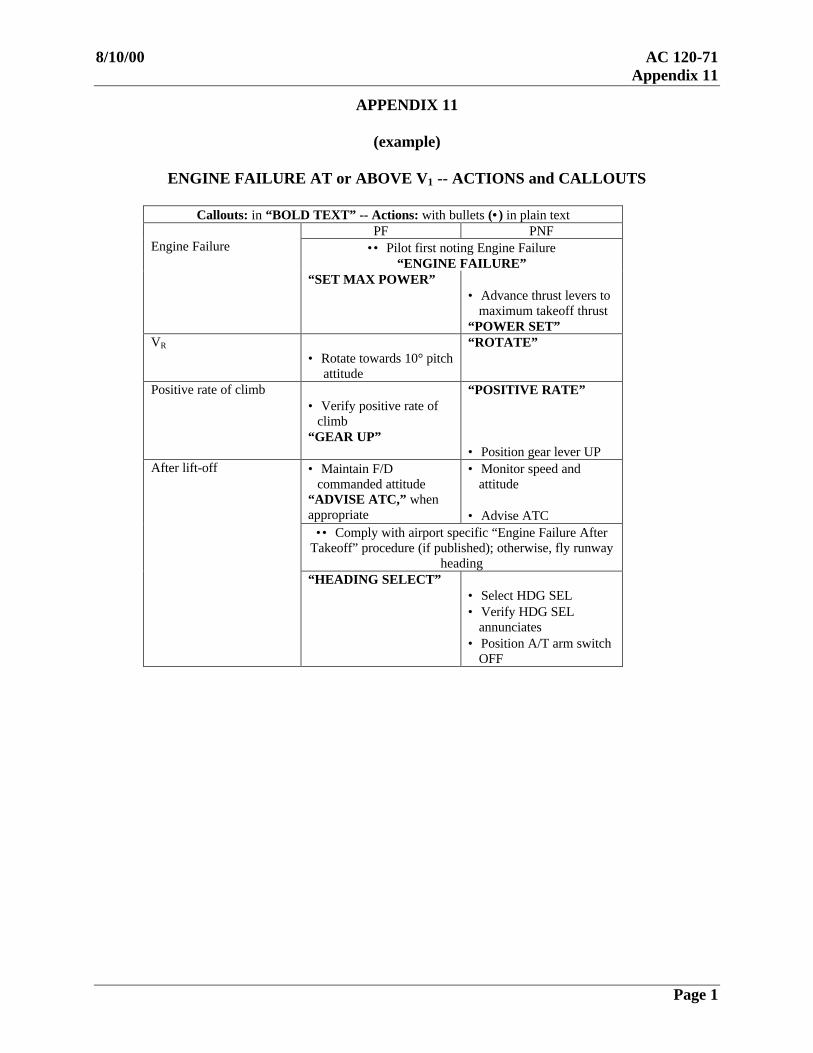
APPENDIX 11
(example)
ENGINE FAILURE AT or ABOVE V1 -- ACTIONS and CALLOUTS
Callouts: in “BOLD TEXT” -- Actions: with bullets (••) in plain textPF PNF
•• Pilot first noting Engine Failure“ENGINE FAILURE”
Engine Failure
“SET MAX POWER”• Advance thrust levers to
maximum takeoff thrust“POWER SET”
VR
• Rotate towards 10° pitchattitude
“ROTATE”
Positive rate of climb• Verify positive rate of
climb“GEAR UP”
“POSITIVE RATE”
• Position gear lever UP• Maintain F/D
commanded attitude“ADVISE ATC,” whenappropriate
• Monitor speed andattitude
• Advise ATC•• Comply with airport specific “Engine Failure After
Takeoff” procedure (if published); otherwise, fly runwayheading
After lift-off
“HEADING SELECT”• Select HDG SEL• Verify HDG SEL
annunciates• Position A/T arm switch
OFF

AC 120-71 8/10/00Appendix 11
Page 2
APPENDIX 11 (con’t)
ENGINE FAILURE AT or ABOVE V1 -- ACTIONS and CALLOUTS
Callouts: in “BOLD TEXT” -- Actions: with bullets (••) in plain textPF PNFClimbing
through 1,000’AFE orobstructionclearancealtitude (OCA),whichever ishigher
“VERTICAL SPEED PLUS100”
• Reduce pitch and accelerate“FLAPS______”(Retract flaps on flap retractionspeed schedule)
• Select VERT SPD to+100 FPM
• Select proper flapsetting, when requested
At flapretraction
speed
“FLAPS UP”• Retract flaps
AtVREF 30 + 80
“FLIGHT LEVEL CHANGE,MAXIMUM CONTINUOUSTHRUST, ENGINE _______CHECKLIST, AFTERTAKEOFF CHECKLIST”
• Select FL CH• Press CON on TMSP• Set MCT“POWER SET”• Accomplish appropriate
checklist“ENGINE _________CHECKLISTCOMPLETE”• Accomplish After
Takeoff Checklist

8/10/00 AC 120-71Appendix 12
Page 1 (and 2)
APPENDIX 12
(example)
WINDSHEAR – TAKEOFF WHILE on the RUNWAY -- RECOVERY TECHNIQUE
Takeoff While on The RunwayRecovery Technique
• THRUST• Apply thrust aggressively (Firewall Power)
• PITCH• Push go-around switch• Rotate toward 15° no later than 2,000 ft. remaining• Increase beyond 15° if required to lift off• Follow flight director commands
Note: After lift-off, follow After Lift-off Recovery Technique
After Lift-off/On Approach WindshearRecovery Technique
• THRUST• Apply thrust aggressively (Firewall Power)
• PITCH• Push either go-around switch• Adjust toward 15°• Follow flight director commands• Increase beyond 15° if required to ensure
acceptable flight path• Always respect stickshaker
• CONFIGURATION• Maintain existing configuration
Note: With a WINDSHEAR warning, if normal commands donot result in a substantial rate of climb, the AFDS smoothlytransitions to a 15° pitch attitude or slightly below the pitchlimit indicator, whichever is less.

8/10/00 AC 120-71Appendix 13
Page 1 (and 2)
APPENDIX 13
(example)
GROUND PROXIMITY WARNINGS
Refer to the FOM for Ground Proximity Warning System generalprocedures. See Chapter 13 (in this handbook) for the systemdescription.
BELOW GLIDESLOPE ALERTIf a GLIDESLOPE alert is activated between the altitudes of 1,000’and 150’ AGL, application of power sufficient to bring the airplaneback up toward the glideslope beam center will cancel the alert when itis less than 1.3 dots below the glideslope. The allowable deviationincreases to 2.7 dots at 50’ AGL. This deviation causes an offscaledeflection on the glideslope deviation scale.
GPWS WARNING ESCAPE MANEUVER
If a GPWS “PULL UP” warning or “TERRAIN” alert occurs at nightor in IMC, perform the following maneuver entirely from memory:
Callouts: in “BOLD TEXT” -- Actions: with bullets (••) in plain text
Step PF PNF
1
Thrust• Auto throttles – disconnect• “FIREWALL POWER,” set
firewall thrustPitch• Autopilot – disconnect• Roll wings level• Rotate (3°/sec) to 20° pitch
attitude. If GPWS warningcontinues – increase pitch(respect stickshaker/buffet)
2
Configuration• Speedbrakes – retract• Do not alter gear/flap
configuration
3 • Climb to safe altitude
4• Resume normal flight. Retract
flaps on flap retraction speedschedule.
• Verify all actions have beencompleted and call out anyomissions• Monitor radio altimeter, and callout information on flight path (e.g.,“300 FEET DESCENDING; 400FEET CLIMBING,” etc.)
• Call out safe altitude (e.g.,“MSA IS 3,400 FEET”)• Advise ATC

8/10/00 AC 120-71Appendix 14
Page 1 (and 2)
APPENDIX 14
(example)
DESCENT PLANNING GUIDE for VISUAL APPROACHES

8/10/00 AC 120-71Appendix 15
Page 1 (and 2)
APPENDIX 15
(example)
DESCENT PLANNING for VISUAL APPROACHES
DESCENT PLANNING for VISUAL APPROACHES
At each airport, ATC has established descent profiles to vector aircraft to intercept aninstrument approach. However, pilots are cleared for visual approaches with thedescent profile at the discretion of the pilot. If the pilot’s descent profile does notresult in a stabilized visual approach by 500’ AFE, then a missed approach must beexecuted (FOM page 5-37).
Visual approaches can be difficult. The wide range of variables, such as position andaltitude when cleared for the approach, the lack of glideslope information, andestablishing separation from a variety of visual traffic all contribute to thecomplexity. The secret to flying a good visual approach is accurate descent planning.This requires analysis at sequential points during the descent/approach, and makingcorrections to altitude and airspeed.
The Descent Planning Guide provides suggested reference points or “gates” to assistin analyzing the descent to arrive at 500’ AFE in a stabilized condition. As youprogress through these “gates,” it is important that any deviations be correctedimmediately to arrive at the next “gate” within the parameters. The longer the delayin making a correction, the greater the chance of arriving at 500’ AFE in anunstabilized condition.
During the early stages of the descent, corrections to altitude and/or airspeed canusually be done using speedbrakes. If in the latter stages of the descent/approach, orif speedbrakes are not effective in correcting to the desired airspeed/altitude, considerextending the landing gear to assist in increasing rate of descent and/or deceleration.Extending flaps and slats to increase deceleration or descent rate is not as effective asthe use of speedbrakes and gear extension.
Utilizing the FMC to reference the landing runway is an excellent technique for avisual approach. This will easily establish a DME reference to the landing runwayfor the targeted “gates.” The key to a successful visual approach is to plan and makecorrections early.

8/10/00 AC 120-71Appendix 16
Page 1
APPENDIX 16
(example)
PRELIGHT
PreflightPreflight (Page 1 of 2)
CAPTAIN FIRST OFFICER
The first pilot on the flight deck will determine the aircraft maintenance status prior to actuating switches andcontrols.
Brief the lead flight attendant (see FOM, chapter 9).Accomplish the captain’s preflight.
After fueling is complete, verify that the fuel loadon board meets the requirements of the dispatchrelease and is adequate for the route of flight.
Accomplish the exterior preflight.
Accomplish the first officer’s preflight.
Record the current ATIS information.
Note: The captain may accomplish this step if itwill expedite the departure process.
When the fuel slip becomes available, review it forany discrepancies, and perform the reasonablenesscheck (see FOM, chapter 5). Verify that the fuel onboard meets the requirements of the dispatch releaseand the flight plan.
Check the ECAM FUEL page to verify the total fuelload and the proper distribution.
Obtain and print the ATC clearance using ACARS Predeparture Clearance (PDC) procedures. If ACARS PDCis not available, obtain the ATC clearance using voice procedures at a time convenient to both crewmembers.The captain may ask the first officer to call for the clearance or the first officer may initiate the call afterensuring the captain is prepared to listen as the clearance is received. The captain will monitor the clearance asit is copied by the first officer.
Verify that the proper clearance altitude andtransponder code are set.
Ensure that the cleared route is the active FMGCroute, or modify as required.
Set the clearance altitude in the FCU ALT window.
Set the transponder code.
Verify that the cleared route is the active FMGC route.
Set the required navigation frequencies and courses for the departure. If required, use the RAD NAV page tomodify the frequencies and courses.
Caution: Frequencies and courses set by the pilot must be cleared when no longer required.
Review the preliminary MGL (see FOM, chapter 8). This will enable the crew to plan the anticipated runway,flap setting, and FLEX capability.
At a convenient time prior to engine start, give apilot briefing to ensure an understanding by bothpilots as to the conduct of the flight (see FOM,chapter 9).

AC 120-71 8/10/00Appendix 16
Page 2
APPENDIX 16 (con’t)
(example)
PREFLIGHT
Preflight (Page 2 of 2)CAPTAIN FIRST OFFICER
♦ Call for the PREFLIGHT CHECK. Verify, asappropriate, and respond to the PREFLIGHTCHECK.
◊ Read, verify as appropriate, and respond tothe PREFLIGHT CHECK.
Announce “PREFLIGHT CHECK COMPLETE.”
If the takeoff weight data becomes available prior toengine start, complete the initialization on INITpage B. Insert ZFW and BLOCK FUEL.

8/10/00 AC 120-71Appendix 17
Page 1
APPENDIX 17
(example)
CREW BRIEFINGS
Pilot Briefing
The purpose of the pilot briefing is to enhance communications on the flight deckand to promote effective teamwork. Each crewmember is expected to perform asan integral part of the team. The briefing should establish a mutual understandingof the specific factors appropriate for the flight.
A pilot briefing will be given prior to starting engines for the first flight of the day(subsequent flight, if applicable). The captain determines the length and detail ofthe briefing. Factors to consider include:
• Experience level of the pilots• Special MEL procedures as a result of inoperative components• Altimeter setting units• Use of delayed engine start and/or engine out taxi procedures• Presence of armed passengers, when applicable
When personnel occupy the extra crew seat(s), ensure they understand the use ofoxygen/interphone operations and emergency exits, and sterile flight deckprocedures.
Takeoff Briefing
A Takeoff Briefing will be given prior to takeoff. Factors to consider include:
• Takeoff weather conditions• Runway surface conditions• NOTAMS• Departure review• Obstructions and high terrain• Closeout weight and balance message/takeoff numbers• Critical conditions affecting the GO/NO GO decision (e.g., gross weight
limited takeoff, wet or slippery runway, crosswind, aircraft malfunctions)• Birdstrike potential, if applicable

AC 120-71 8/10/00Appendix 17
Page 2
APPENDIX 17 (con’t)
(example)
CREW BRIEFINGS
Flight Attendant Briefing
The purpose of the flight attendant briefing is to develop a team concept betweenthe flight deck and cabin crew. An ideal developed team must share knowledgerelating to flight operations, review individual responsibilities, share personalconcerns, and have a clear understanding of expectations.Upon flight origination or whenever a crew change occurs, the captain willconduct a verbal briefing, preferably with all the flight attendants. However,preflight duties, passenger boarding, rescheduling, etc. may make it impractical tobrief the entire flight attendant complement. Regardless of time constraints,company policy is that the captain must brief the lead flight attendant. Thebriefing will be supplemented with a completed Flight Attendant Briefing Form.The briefing should cover the following items:• Logbook discrepancies that may affect flight attendant responsibilities or
passenger comfort (e.g., coffee maker inop, broken seat backs, manualpressurization, etc.)
• Weather affecting the flight (e.g., turbulence – including appropriate codelevels, thunderstorms, weather near minimums, etc.). Provide the time whenthe weather may be encountered rather than a distance or location (e.g., “Code4 Turbulence can be expected approximately one hour after takeoff.”)
• Delays, unusual operations, non-routine operations (e.g., maintenance delays,ATC delays, re-routes, etc.)
• Shorter than normal taxi time or flight time which may affect preflightannouncements or cabin service.
• Any other items that may affect the flight operation or in-flight service such ascatering, fuel stops, armed guards, etc.
• A review of the sterile flight deck policy, responsibility for PAannouncements when the Fasten Seat Belt sign is turned on during cruise,emergency evacuation commands, or any other items appropriate to the flight.
During the briefing, the captain should solicit feedback for operational concerns(e.g., does each person understand the operation of the emergency exits andequipment). The captain should also solicit feedback for information which mayaffect expected team roles. Empower each crewmember to take a leadership rolein ensuring all crewmembers are made aware of any potential item that mightaffect the flight operation.The lead flight attendant will inform the captain of any inoperative equipment andthe number of flight attendants on board.The captain will inform the lead flight attendant when there are significantchanges to the operation of the flight after the briefing has been conducted.