submit documentation feedback - ti.com · 1 introduction application report slza002– september...
TRANSCRIPT
Moisture-Sensitivity Classification ofFlange-Mounted Packages at
Texas Instruments
Application Report
Literature Number: SLZA002
September 2007

2 SLZA002–September 2007Submit Documentation Feedback
Contents
1 Introduction................................................................................................................ 52 Problem Statement...................................................................................................... 63 Moisture Sensitivity Testing of Flange-Mounted Packages............................................... 8
3.1 Delamination Mitigation Techniques........................................................................... 9
3.2 Competitive Analysis ........................................................................................... 10
4 Conclusion ............................................................................................................... 13
SLZA002–September 2007 Table of Contents 3Submit Documentation Feedback

List of Figures
1 Flange-Mounted Packages and Packages With Exposed Die Paddle ............................................... 52 Construction Differences Between an Over-Molded and SMT Package With Exposed Die Paddle ............. 63 Factors Affecting Die Paddle Delamination .............................................................................. 64 Cross Section Showing Mold Compound to Die Pad Delamination................................................... 75 Typical Failure Mode of Down-Bond Wires Located on Die Paddle Delamination Areas.......................... 76 Stitch-Bond Options........................................................................................................ 107 TO252-3 Post MSL Results............................................................................................... 118 SOT223-4 Post MSL Results ............................................................................................. 129 TO263 Post MSL Results ................................................................................................. 13
4 List of Figures SLZA002–September 2007Submit Documentation Feedback

1 Introduction
Application ReportSLZA002–September 2007
Moisture-Sensitivity Classification of Flange-MountedPackages at Texas Instruments
Edgar R. Zuniga ........................................................................................................ HVAL PackagingLance Wright ...................................................................................................................................
Moisture-sensitivity testing (MSL) of flange-mounted packages is performed using the Joint IndustryStandard IPC/J-STD-020C guidelines for surface mount technology (SMT) packages.
Although the same testing methodology is required for all standard SMT packages like SOP, QFP orTSOP; flange-mounted and SMT packages with exposed die paddle (see Figure 1), require additionaltesting to properly assess the MSL performance of the package and its reliability for lead-free processing.
Figure 1. Flange-Mounted Packages and Packages With Exposed Die Paddle
This application report explains the methodologies that can be used to assess and improve the robustnessof flange-mounted and SMT packages with exposed die paddle and down bonds.
SLZA002–September 2007 Moisture-Sensitivity Classification of Flange-Mounted Packages at Texas Instruments 5Submit Documentation Feedback
www.ti.com
2 Problem Statement
Over-Molded Package
Exposed Die Paddle Package
Die paddle/Die size ratio Bond Line Thickness
Smaller Die Paddle
Large Die Paddle
Thick Bond Line Thickness
Thin Bond Line Thickness
Die Paddle Finish
Inc
rea
se
in
Die
Pa
dd
le D
ela
min
ati
on
Problem Statement
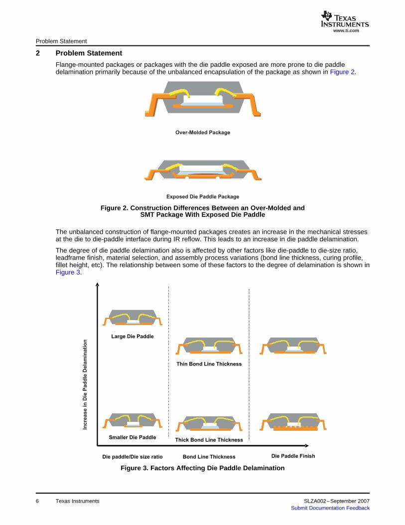
Flange-mounted packages or packages with the die paddle exposed are more prone to die paddledelamination primarily because of the unbalanced encapsulation of the package as shown in Figure 2.
Figure 2. Construction Differences Between an Over-Molded andSMT Package With Exposed Die Paddle
The unbalanced construction of flange-mounted packages creates an increase in the mechanical stressesat the die to die-paddle interface during IR reflow. This leads to an increase in die paddle delamination.
The degree of die paddle delamination also is affected by other factors like die-paddle to die-size ratio,leadframe finish, material selection, and assembly process variations (bond line thickness, curing profile,fillet height, etc). The relationship between some of these factors to the degree of delamination is shown inFigure 3.
Figure 3. Factors Affecting Die Paddle Delamination
6 Texas Instruments SLZA002–September 2007Submit Documentation Feedback

www.ti.com
Problem Statement
Delamination between the die paddle and the mold compound may not be a major problem unless thedelamination intersects the location of downbonds located on the die paddle.
Die paddle delamination between the backside of the die and the paddle itself may or may not be aproblem depending on the thermal requirements of the device. Because flange-mounted packages orpackages with exposed pad are primarily used on devices requiring good heat dissipation, delamination atthis interface area could be a major reliability problem, in some instances causing the device to shut offdue to overheating.
This document addresses only the issues related with delamination between the mold compound and thedie paddle in conjunction with down bonded wires. The reliability issues related to delamination betweenthe backside of the die and the die paddle is not discussed on this dcoument, although the problem hasbeen the subject of extensive work done at Texas Instruments.
When delamination between the mold compound and the die paddle is present, the mold compound isfree to move in relation to the die paddle during temperature cycle excursions. Because of the differencesin coefficient of thermal expansion between the die paddle, the silicon die, and the mold compound, themovement of the mold compound could cause the wires to break at the die paddle-wire interconnectioninterface as shown in Figure 4. Figure 5 shows a typical wire breakage failure mode during IR reflow orafter temperature cycle if delamination is present.
Figure 4. Cross Section Showing Mold Compound to Die Pad Delamination
The broken wire bonds depicted on Figure 5 were found after subjecting packages to the JEDEC 020specification followed by 1000 temperature cycles (–65 to 150°C) as specified by JESD22-A104-B.
Figure 5. Typical Failure Mode of Down-Bond Wires Locatedon Die Paddle Delamination Areas
SLZA002–September 2007 Texas Instruments 7Submit Documentation Feedback
www.ti.com
3 Moisture Sensitivity Testing of Flange-Mounted Packages
Moisture Sensitivity Testing of Flange-Mounted Packages
The presence of delamination may or may not cause the wire bond to break (wire stitch location is also afactor). The delamination may not even cause the device to fail even if the wire is broken. Although thebond wire may no longer be “hard” connected to the die paddle, the device may still pass electrical testing.This is because the wire may still be in electrical contact to the die paddle as a result of the pressureexerted by the mold compound.
This condition may lead to errors when judging the MSL test results. The implications could result in therelease of a package with marginal MSL performance.
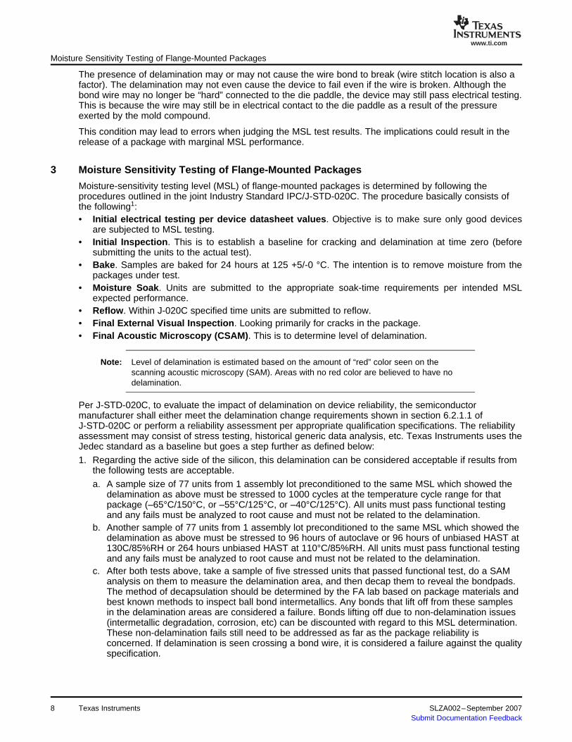
Moisture-sensitivity testing level (MSL) of flange-mounted packages is determined by following theprocedures outlined in the joint Industry Standard IPC/J-STD-020C. The procedure basically consists ofthe following1:• Initial electrical testing per device datasheet values. Objective is to make sure only good devices
are subjected to MSL testing.• Initial Inspection. This is to establish a baseline for cracking and delamination at time zero (before
submitting the units to the actual test).• Bake. Samples are baked for 24 hours at 125 +5/-0 °C. The intention is to remove moisture from the
packages under test.• Moisture Soak. Units are submitted to the appropriate soak-time requirements per intended MSL
expected performance.• Reflow. Within J-020C specified time units are submitted to reflow.• Final External Visual Inspection. Looking primarily for cracks in the package.• Final Acoustic Microscopy (CSAM). This is to determine level of delamination.
Note: Level of delamination is estimated based on the amount of “red” color seen on thescanning acoustic microscopy (SAM). Areas with no red color are believed to have nodelamination.
Per J-STD-020C, to evaluate the impact of delamination on device reliability, the semiconductormanufacturer shall either meet the delamination change requirements shown in section 6.2.1.1 ofJ-STD-020C or perform a reliability assessment per appropriate qualification specifications. The reliabilityassessment may consist of stress testing, historical generic data analysis, etc. Texas Instruments uses theJedec standard as a baseline but goes a step further as defined below:
1. Regarding the active side of the silicon, this delamination can be considered acceptable if results fromthe following tests are acceptable.
a. A sample size of 77 units from 1 assembly lot preconditioned to the same MSL which showed thedelamination as above must be stressed to 1000 cycles at the temperature cycle range for thatpackage (–65°C/150°C, or –55°C/125°C, or –40°C/125°C). All units must pass functional testingand any fails must be analyzed to root cause and must not be related to the delamination.
b. Another sample of 77 units from 1 assembly lot preconditioned to the same MSL which showed thedelamination as above must be stressed to 96 hours of autoclave or 96 hours of unbiased HAST at130C/85%RH or 264 hours unbiased HAST at 110°C/85%RH. All units must pass functional testingand any fails must be analyzed to root cause and must not be related to the delamination.
c. After both tests above, take a sample of five stressed units that passed functional test, do a SAManalysis on them to measure the delamination area, and then decap them to reveal the bondpads.The method of decapsulation should be determined by the FA lab based on package materials andbest known methods to inspect ball bond intermetallics. Any bonds that lift off from these samplesin the delamination areas are considered a failure. Bonds lifting off due to non-delamination issues(intermetallic degradation, corrosion, etc) can be discounted with regard to this MSL determination.These non-delamination fails still need to be addressed as far as the package reliability isconcerned. If delamination is seen crossing a bond wire, it is considered a failure against the qualityspecification.
8 Texas Instruments SLZA002–September 2007Submit Documentation Feedback
www.ti.com
3.1 Delamination Mitigation Techniques
Moisture Sensitivity Testing of Flange-Mounted Packages
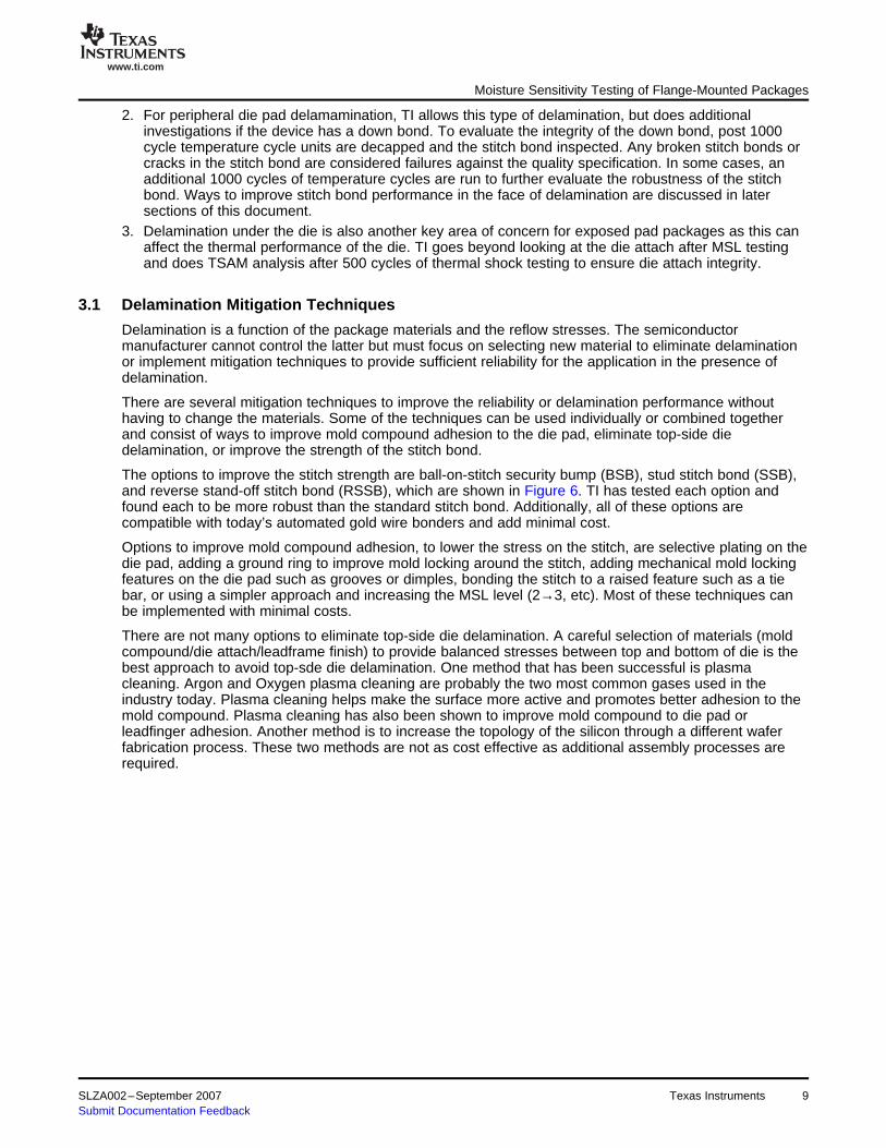
2. For peripheral die pad delamamination, TI allows this type of delamination, but does additionalinvestigations if the device has a down bond. To evaluate the integrity of the down bond, post 1000cycle temperature cycle units are decapped and the stitch bond inspected. Any broken stitch bonds orcracks in the stitch bond are considered failures against the quality specification. In some cases, anadditional 1000 cycles of temperature cycles are run to further evaluate the robustness of the stitchbond. Ways to improve stitch bond performance in the face of delamination are discussed in latersections of this document.
3. Delamination under the die is also another key area of concern for exposed pad packages as this canaffect the thermal performance of the die. TI goes beyond looking at the die attach after MSL testingand does TSAM analysis after 500 cycles of thermal shock testing to ensure die attach integrity.
Delamination is a function of the package materials and the reflow stresses. The semiconductormanufacturer cannot control the latter but must focus on selecting new material to eliminate delaminationor implement mitigation techniques to provide sufficient reliability for the application in the presence ofdelamination.
There are several mitigation techniques to improve the reliability or delamination performance withouthaving to change the materials. Some of the techniques can be used individually or combined togetherand consist of ways to improve mold compound adhesion to the die pad, eliminate top-side diedelamination, or improve the strength of the stitch bond.
The options to improve the stitch strength are ball-on-stitch security bump (BSB), stud stitch bond (SSB),and reverse stand-off stitch bond (RSSB), which are shown in Figure 6. TI has tested each option andfound each to be more robust than the standard stitch bond. Additionally, all of these options arecompatible with today’s automated gold wire bonders and add minimal cost.
Options to improve mold compound adhesion, to lower the stress on the stitch, are selective plating on thedie pad, adding a ground ring to improve mold locking around the stitch, adding mechanical mold lockingfeatures on the die pad such as grooves or dimples, bonding the stitch to a raised feature such as a tiebar, or using a simpler approach and increasing the MSL level (2→3, etc). Most of these techniques canbe implemented with minimal costs.
There are not many options to eliminate top-side die delamination. A careful selection of materials (moldcompound/die attach/leadframe finish) to provide balanced stresses between top and bottom of die is thebest approach to avoid top-sde die delamination. One method that has been successful is plasmacleaning. Argon and Oxygen plasma cleaning are probably the two most common gases used in theindustry today. Plasma cleaning helps make the surface more active and promotes better adhesion to themold compound. Plasma cleaning has also been shown to improve mold compound to die pad orleadfinger adhesion. Another method is to increase the topology of the silicon through a different waferfabrication process. These two methods are not as cost effective as additional assembly processes arerequired.
SLZA002–September 2007 Texas Instruments 9Submit Documentation Feedback

www.ti.com
3.2 Competitive Analysis
Moisture Sensitivity Testing of Flange-Mounted Packages
Figure 6. Stitch-Bond Options
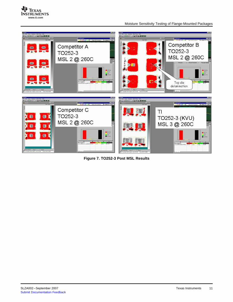
Flange-mounted packages like the TO263, TO252, SOT223 packages, due to its unbalanced construction,are very sensitive to moisture ingression, and delamination around the die is very typical. One key factor isthat the die is usually small compared to the die paddle. During the TI development cycle of the TO263package (TI code KTT), three qualification attempts failed due to broken standard stitch bonds on thedown bond wires before a new material set was chosen and several mitigation techniques employed. TInow has a very robust TO263 package that has exceeded all test requirements. Due to the difficultly inachieving a Pb-free solution that passed all qualification requirements, TI investigated the performance ofcompetitor MSL to gauge the range of delamination/package robustness in the industry on severaldifferent types of flange mount packages. The results from the analysis study are shown in Figure 7 –Figure 9.
The data shows a range of 100% delamination to zero delamination with the TI devices having the lowestlevels of delamination. It should be noted that on the TO-263 and TO-252 packages, the TI devices arerated at MSL 3 whereas the other devices have a more aggressive MSL rating. Lower MSL levels tend toshow more delamination but in some cases, the delamination performance can be the same at all MSLlevels. TI’s internal testing has shown that increased levels of delamination have an impact on long termreliability. Another observation is that some IC suppliers allow for top-side die delamination that is notpresent on the TI devices. Issues with top-side die delamination and component reliability are welldocumented in the industry and need not be repeated here. It is best not to have this type of delamination.When focusing on the areas around the die, the TI devices have zero or partial delamination whereas allthe other supplier devices have 100% delamination. In the case of SOT-223, the MSL rating is the same.As previously discussed, this type of delamination can affect down bond robustness. This is why it isrecommended to decap after the appropriate stress tests to validate the integrity of the stitch bond.Additionally, electrical testing does not always capture fractured stitch bonds. This has been proven in TI’sfailed qualification. It takes longer than the standard testing cycles to show a complete “open.” None of theanalyzed devices were submitted for reliability testing due to insufficient sample size, but from thiscompetitive analysis, it is clear that the quality policies and practices are not the same acrosssemiconductor suppliers.
10 Texas Instruments SLZA002–September 2007Submit Documentation Feedback
www.ti.com
Moisture Sensitivity Testing of Flange-Mounted Packages
Figure 7. TO252-3 Post MSL Results
SLZA002–September 2007 Texas Instruments 11Submit Documentation Feedback

www.ti.com
Moisture Sensitivity Testing of Flange-Mounted Packages
Figure 8. SOT223-4 Post MSL Results
12 Texas Instruments SLZA002–September 2007Submit Documentation Feedback

www.ti.com
4 Conclusion
Conclusion
Figure 9. TO263 Post MSL Results
Delamination is not a desired result in packages as it can impact device reliability. However, due topackage construction, cost pressures, and reflow temperature requirements, it is inevitable on somedevices. There are several techniques that can be used to improve the delamination performance orimprove reliability, but they do not come without a price. This document recommends that more attentionbe paid to delaminated areas within a package by doing post stress investigations and evaluating differentmitigation techniques. These practices, along with the appropriate MSL rating, can lead to improveflange-mount packaging reliability.
SLZA002–September 2007 Texas Instruments 13Submit Documentation Feedback

IMPORTANT NOTICE
Texas Instruments Incorporated and its subsidiaries (TI) reserve the right to make corrections, modifications, enhancements,improvements, and other changes to its products and services at any time and to discontinue any product or service without notice.Customers should obtain the latest relevant information before placing orders and should verify that such information is current andcomplete. All products are sold subject to TI’s terms and conditions of sale supplied at the time of order acknowledgment.
TI warrants performance of its hardware products to the specifications applicable at the time of sale in accordance with TI’sstandard warranty. Testing and other quality control techniques are used to the extent TI deems necessary to support thiswarranty. Except where mandated by government requirements, testing of all parameters of each product is not necessarilyperformed.
TI assumes no liability for applications assistance or customer product design. Customers are responsible for their products andapplications using TI components. To minimize the risks associated with customer products and applications, customers shouldprovide adequate design and operating safeguards.
TI does not warrant or represent that any license, either express or implied, is granted under any TI patent right, copyright, maskwork right, or other TI intellectual property right relating to any combination, machine, or process in which TI products or servicesare used. Information published by TI regarding third-party products or services does not constitute a license from TI to use suchproducts or services or a warranty or endorsement thereof. Use of such information may require a license from a third party underthe patents or other intellectual property of the third party, or a license from TI under the patents or other intellectual property of TI.
Reproduction of TI information in TI data books or data sheets is permissible only if reproduction is without alteration and isaccompanied by all associated warranties, conditions, limitations, and notices. Reproduction of this information with alteration is anunfair and deceptive business practice. TI is not responsible or liable for such altered documentation. Information of third partiesmay be subject to additional restrictions.
Resale of TI products or services with statements different from or beyond the parameters stated by TI for that product or servicevoids all express and any implied warranties for the associated TI product or service and is an unfair and deceptive businesspractice. TI is not responsible or liable for any such statements.
TI products are not authorized for use in safety-critical applications (such as life support) where a failure of the TI product wouldreasonably be expected to cause severe personal injury or death, unless officers of the parties have executed an agreementspecifically governing such use. Buyers represent that they have all necessary expertise in the safety and regulatory ramificationsof their applications, and acknowledge and agree that they are solely responsible for all legal, regulatory and safety-relatedrequirements concerning their products and any use of TI products in such safety-critical applications, notwithstanding anyapplications-related information or support that may be provided by TI. Further, Buyers must fully indemnify TI and itsrepresentatives against any damages arising out of the use of TI products in such safety-critical applications.
TI products are neither designed nor intended for use in military/aerospace applications or environments unless the TI products arespecifically designated by TI as military-grade or "enhanced plastic." Only products designated by TI as military-grade meet militaryspecifications. Buyers acknowledge and agree that any such use of TI products which TI has not designated as military-grade issolely at the Buyer's risk, and that they are solely responsible for compliance with all legal and regulatory requirements inconnection with such use.
TI products are neither designed nor intended for use in automotive applications or environments unless the specific TI productsare designated by TI as compliant with ISO/TS 16949 requirements. Buyers acknowledge and agree that, if they use anynon-designated products in automotive applications, TI will not be responsible for any failure to meet such requirements.
Following are URLs where you can obtain information on other Texas Instruments products and application solutions:
Products Applications
Amplifiers amplifier.ti.com Audio www.ti.com/audio
Data Converters dataconverter.ti.com Automotive www.ti.com/automotive
DSP dsp.ti.com Broadband www.ti.com/broadband
Interface interface.ti.com Digital Control www.ti.com/digitalcontrol
Logic logic.ti.com Military www.ti.com/military
Power Mgmt power.ti.com Optical Networking www.ti.com/opticalnetwork
Microcontrollers microcontroller.ti.com Security www.ti.com/security
RFID www.ti-rfid.com Telephony www.ti.com/telephony
Low Power www.ti.com/lpw Video & Imaging www.ti.com/videoWireless
Wireless www.ti.com/wireless
Mailing Address: Texas Instruments, Post Office Box 655303, Dallas, Texas 75265Copyright © 2007, Texas Instruments Incorporated