submitted to ieee trans on pami, 2006 1 multi …mturk/pubs/ferispami08.pdfsubmitted to ieee trans...
TRANSCRIPT
SUBMITTED TO IEEE TRANS ON PAMI, 2006 1
Multi-Flash Stereopsis: Depth Edge PreservingStereo with Small Baseline Illumination
Rogerio Feris1, Ramesh Raskar2, Longbin Chen1, Karhan Tan3, Matthew Turk1
1University of California, Santa Barbara2Mitsubishi Electric Research Labs
3Epson Palo Alto Laboratory
Abstract
Traditional stereo matching algorithms are limited in their ability to produce accurate results neardepth discontinuities, due to partial occlusions and violation of smoothness constraints. In this paper, weuse small baseline multi-flash illumination to produce a rich set of feature maps that enable acquisition ofdiscontinuity preserving point correspondences. First, from a single multi-flash camera, we formulate aqualitative depth map using a gradient domain method that encodes object relative distances. Then,in a multiview setup, we exploit shadows created by light sources to compute an occlusion map.Finally, we demonstrate the usefulness of these feature maps by incorporating them into two differentdense stereo correspondence algorithms, the first based on local search and the second based on beliefpropagation. Experimental results show that our enhanced stereo algorithms are able to extract highquality, discontinuity preserving correspondence maps from scenes that are extremely challenging forconventional stereo methods. We also demonstrate that small baseline illumination can be useful tohandle specular reflections in stereo imagery. Different from most existing active illumination techniques,our method is simple, inexpensive, compact, and requires nocalibration of light sources.
Index Terms
stereo matching, multi-flash imaging, depth discontinuities
I. INTRODUCTION
Stereo vision algorithms have been investigated for many years in computer vision in order
to infer 3D structure from images captured with different viewpoints. The most challenging
problem in stereo reconstruction is the establishment of visual correspondence among images.
This is a fundamental operation that is the starting point ofmost geometric algorithms for 3D
shape reconstruction and motion estimation.
Intuitively, a complete solution to the correspondence problem would produce: (1) a mapping
between pixels in different images where there is a correspondence, and (2) labels for scene
points that are not visible from all views – where there isno correspondence.

SUBMITTED TO IEEE TRANS ON PAMI, 2006 2
In the past two decades, intense interest in the correspondence problem has produced many
excellent algorithms for solving the first part of the problem. With a few exceptions, most
algorithms for dense correspondence do not address occlusions explicitly [1]. The occlusion
problem is difficult partly because distinguishing sharp discontinuities in depth (also known
as depth edges or occluding contours) from edges caused by reflectance changes remains a
fundamental unsolved vision problem [2].
A promising method for addressing the occlusion problem is to use active illumination.
In fact, many techniques that make use of lighting changes have been proposed to solve the
correspondence problem in stereo reconstruction [3], [4],[5]. In general these techniques offer a
tradeoff between accuracy and cost of the equipment, as wellas other issues such as compactness,
light source calibration, and number of images to be acquired. Other active shape reconstruction
approaches such as photometric stereo [6] and shape from shadows [7] avoid the correspondence
problem by using multiple images of the scene captured with variable illumination, but fixed
viewpoint. A common limitation of these methods is that the light sources must surround the
object in order to create sufficient shading and shadow variation from (estimated or known) 3D
light positions. This requires a fixed lighting rig, which limits the application of these techniques
to laboratory and industrial settings; such a setup is impractical to build into a self-contained
camera.
Recently, we have demonstrated a reliable method for detecting depth edges in real world
scenes [8]. Our approach is based on a simple and inexpensivemodification of the capture setup:
a multi-flash camera is used with flashes strategically positioned to cast shadows along depth
discontinuities. We have shown the effectiveness of multi-flash imaging in different vision and
graphics applications, including non-photorealistic rendering [8], medical imaging [9], specular
reflection reduction [10], and visual recognition [11].
In this paper, we propose a stereo framework based on small baseline active illumination,
which allows accurate correspondence maps on scenes with high depth complexity and specular
reflections. In particular, we show how multi-flash illumination can be used to produce a rich

SUBMITTED TO IEEE TRANS ON PAMI, 2006 3
set of feature maps that are useful in dense 3D reconstruction. Our feature maps are based on
important cues, including: (1) depth edges, (2) the sign of the depth edge (which tells the side
of the occluding object), and (3) information about object relative distances.
Starting with these cues, we derive a qualitative depth map from a single multi-flash camera.
In a multiview setup, we show how binocular half-occluded pixels can be explicitly and reliably
labeled, along with depth edges. We demonstrate how the feature maps can be used effectively by
incorporating them into two different dense stereo correspondence algorithms, the first based on
local search and the second based on belief propagation. Compared to passive stereo techniques,
our method offers significant improvements in accuracy, especially in regions near depth discon-
tinuities. Our feature maps could be used to complement existing active lighting approaches and
our method offers the advantages of being simple, inexpensive, and compact, while requiring no
calibration of light sources.
The remainder of this paper is organized as follows: SectionII reviews related work and the
basic technique to detect depth edges with multi-flash illumination. Then, a brief overview about
the implementation setups used in our work is given in Section III. In Section IV, we formulate
a qualitative depth map, followed by the computation of an occlusion map in Section V. The
usefulness of these feature maps are demonstrated in local and global stereo algorithms in Section
VI. Finally, Section VII discusses pros and cons of our approach and provides comparison with
existing techniques.
II. RELATED WORK
Although significant progress has been made in dense two-frame stereo matching (see [1]
for a comprehensive survey), producing accurate results near depth discontinuities remains a
challenge. In general, dense stereo techniques can be classified as local or global, depending
whether they rely on local window-based computations or theminimization of a global energy
function. In local-based methods, the disparity computation at a given point depends only on
intensity values within a finite window. Clearly, these techniques assume that all pixels within
the window have the same disparity and thus are sensitive near object boundaries. Attempts to

SUBMITTED TO IEEE TRANS ON PAMI, 2006 4
alleviate this problem include the use of adaptive windows [12] and shiftable windows [13].
Occlusion has been modeled explicitly through global optimization approaches based on
dynamic programming [14], [15], [16]. Stereo matching is formulated as finding a minimum cost
path in the matrix of all pairwise matching costs between twocorresponding scanlines. These
techniques, however, often show a streaking effect (as scanlines are matched independently)
and assume ordering constraints, which may be violated withthin objects in the scene. More
recently, global stereo approaches based on Markov Random Fields have received great attention
[17], [1]. These methods minimize an energy function (e.g.,using belief propagation [18] or
graph cuts [19]) that includes a data term and a smoothness term. Although discontinuities and
occlusion can be explicitly modeled [19], [20], intensity edges and junctions are generaly used
as cues for depth discontinuities. Ideally, smoothness constraints should be supressed only at
occluding edges, not at texture or illumination edges.
The correspondence problem can be significantly simplified by using active illumination
methods based on structured light [21], [22]. A structured light system is based on the projection
of a single pattern or a set of patterns onto the scene which isthen viewed by a single camera or
a set of cameras. Time-multiplexing or temporal coding [23], [24] is the most common pattern
projection technique. The basic idea is to project a set of different patterns successively onto the
scene, so that each point viewed by a camera has a specific codeword (formed by the sequence
of illumination values accross the projected patterns). These methods allow accurate computation
of correspondence maps, but are limited to handle dynamic scenes. This issue is addressed by
techniques that project a single pattern with pixel coding based on a spatial neigborhood [3].
However, depth discontinuities pose a problem as local smoothness of the measuring surface is
assumed in order to correctly decode the pixel neighborhood. Other techniques based on colored
patterns [25], and space-time stereo [26], [4] have also been proposed. Overall, compared to
passive stereo techniques, structured light methods offerhigh quality correspondence maps and
3D acquisition, but are in general much more expensive and limited to indoor scenes.
Photometric stereo [27] is a simple, inexpensive active lighting approach that acquires 3D
SUBMITTED TO IEEE TRANS ON PAMI, 2006 5
information without relying on the correspondence problem. Multiple images of the scene are
captured under different illumination conditions (but fixed viewpoint) and used to estimate a field
of surface normals, which is then integrated to produce a surface. Photometric stereo methods
are suitable for reconstructing the shape of objects with uniform albedo, thus complementing
conventional stereo, which is best for textured surfaces with varying reflectance. They work well
for smooth surfaces, but are unstable near depth discontinuities or rapid surface normal changes.
In general, most techniques assume Lambertian surface reflectance, but recent research deals
with spatially varying bidirectional reflectance distribution functions (BRDF) [6].
Helmholtz stereo [5] is a technique that combines active lighting with viewpoint variation
to estimate both surface normals and depth with arbitrary surface reflectance. The idea behind
Helmholtz Stereopsis is to exploit the symmetry of surface reflectance, commonly referred to
as Helmholtz reciprocity. The image acquisition proceeds in two simple steps: first, an image
is acquired with the object/scene illuminated by a single point light source. Then, the positions
of the camera and light source are swapped, and the second image is acquired. By acquiring
the images in this manner, they ensure that for all corresponding points in the images, the ratio
of the outgoing radiance to the incident irradiance is the same. This is, in general, not true for
stereo pairs - unless the surfaces have Lambertian reflectance.
Techniques for shape from shadows (or darkness) [7] build a continuous representation (shad-
owgram) from a moving light source from which continuous depth estimates are possible.
However, it involves a difficult problem of estimating continuous heights and requires accurate
detection of start and end of shadows. Shadow carving was proposed by Savarese et al. [28] as
a technique to refine shape estimation using shadow consistency checks. Bouguet and Perona
[29] proposed a simple and inexpensive system where the usermoves a pencil in front of a light
source to cast moving shadows on the object. The 3D shape of the object is extracted from the
spatial and temporal location of the observed shadow. In general these approaches do not allow
compact setups, due to the assumption of light sources surrounding the object. Good reviews of
shadow-based shape analysis methods are available in [30],[31].
SUBMITTED TO IEEE TRANS ON PAMI, 2006 6
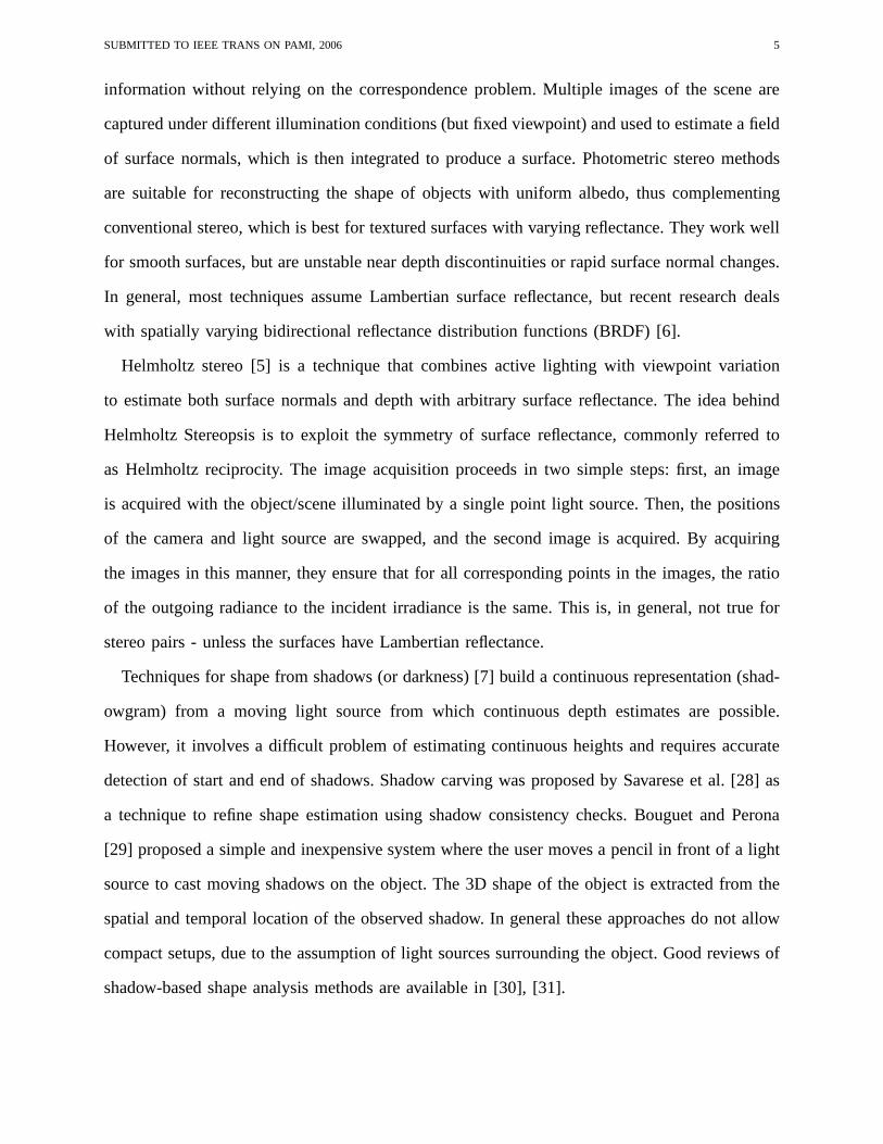
Fig. 1. (a) Multi-flash camera (b) Image taken with left flash. (c) Correspondent ratio image and traversal direction. (d)Computed depth edges. Note that we can obtain the sign of eachdepth edge pixel, indicating which side of the edge is theforeground.
A. Depth Edges with Multi-Flash
Before introducing our techniques, we briefly review the basic idea of detecting depth edges
with multi-flash imaging [8].
The main observation is that when a flash illuminates a scene during image capture, thin
slivers of cast shadow are created at depth discontinuities. Thus, if we can shoot a sequence of
images in which different light sources illuminate the subject from various positions, we can
use the shadows in each image to assemble a depth edge map using the shadow images.
Shadows are detected by first computing ashadow-free image, which can be approximated with
the maximum composite image, created by choosing at each pixel the maximum intensity value
among the image set. The shadow-free image is then compared with the individual shadowed
images. In particular, for each shadowed image, aratio image is computed by performing a
pixel-wise division of the intensity of the shadowed image by the intensity of the maximum
image. Although the pixels in the ratio image are not constant from one point to another, they
are very similar and close to 1.0 for non-shadowed regions, and close to 0.0 for shadowed
regions. This allows us to segment shadows very reliably.
The final step is to traverse each ratio image along its epipolar rays (as given by the respective
light positions) and mark negative transitions as depth edges. We use an implementation setup
with four flashes at left, right, top and bottom positions, which makes the epipolar ray traversal
aligned with horizontal and vertical scanlines. Figure 1 illustrates the main idea of the depth
edge detection algorithm. Note that the sign of the edge is also obtained, indicating which part
is the background and which part is the foreground in a local neighborhood.

SUBMITTED TO IEEE TRANS ON PAMI, 2006 7
III. M ULTI -FLASH IMAGING SETUPS
Throughout this paper, we will investigate different multi-flash imaging setups for obtaining a
qualitative depth map of the scene, detecting occlusion pixels in stereo, and computing disconti-
nuity preserving disparity maps. In this section, we brieflydiscuss the purpose of these different
implementation setups.
Figure 2a shows the basic multi-flash camera setup with four flashes, used to detect depth
edges, as described in Section II-A. This setup uses a 4-megapixel Canon Powershot G3 (see
Figure 1a). A microcontroller board triggers sequentiallythe four flashes mounted around the
camera. The board synchronizes the flashes to the image capture process by sensing the flash
trigger signal from the camera hot shoe. We will show in Section IV that this particular setup
can also be used to obtain a qualitative depth map of the scene
Different camera-flash configurations may be used to combinesmall baseline multi-flash
illumination with stereo reconstruction. Figure 2b shows astereo setup with two cameras where
each camera has its own set of flashes. This setup is particularly useful to detect occlusions in
stereo, as we will show in Section V.
An alternative implementation setup is shown in Figure 2c. In this case, the flashes surround
both cameras, and, for each flash, two images are captured simultaneously by the two cameras.
This setup would be more appropriate to process dynamic scenes (using lights with different
wavelength [44] or triggered in a rapid cyclic sequence). Compared to the setup showed in Figure
2b, it offers advantages in terms of acquisition time, whilerequiring only four light sources.
On the other hand, the top and bottom ratio image traversals for depth edge detection is not
aligned with the pixel grid, since the top and bottom flashes are positioned on the upper and
lower diagonals of the center of projection of the cameras.
Figure 2d shows an implementation setup that uses only one camera with a stereo adapter. With
such adapter, it is possible to obtain the stereo image pair with a single shot, eliminating the need
for camera synchronization. Experiments with this implementation setup will be demonstrated
in Section VI-C.

SUBMITTED TO IEEE TRANS ON PAMI, 2006 8
Fig. 2. Different multi-flash implementation setups. (a) Basic setup used for depth edge detection and qualitative depth mapestimation. (b) Stereo multi-flash setup where each camera has its own flashes. This setup is useful for occlusion detection instereo matching. (c) Stereo setup with flashes surrounding both cameras, for faster acquisition. (c) Flashes surrounding onlyone camera with a Pentax stereo adapter.
IV. QUALITATIVE DEPTH MAP
In this section, we use a single multi-flash camera to derive aqualitative depth map based
on shadow width information. Our method is related to shape from shadow techniques [7], but
differs significantly in methodology. At this point we are not interested in quantitative depth
measurements. Rather, we want to segment the scene, while simultaneously establishing object
depth-order relations and approximate relative distances. This turns out to be valuable prior
information for stereo.
A. Shadow Width Estimation
A natural way of extending our depth edge detection method toestimate shadow width is
to measure the length of regions delimited by a negative transition (which corresponds to the
depth edge) and a positive transition along the epipolar rayin the ratio images. However, finding
the positive transition is not an easy task, due to interreflections and the use of non-point light
sources.
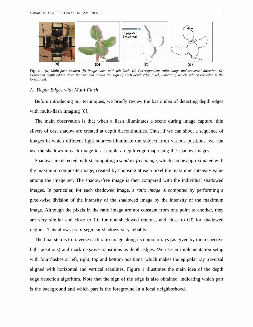
Figure 3a-c illustrates this problem: note that the intensity profile along the vertical scanline
depicted in the ratio image has spurious transitions due to interreflections in the umbra region
and a smooth transition near the end of the shadow (in the penumbra region). Estimation of the
shadow width based on local-area-based edge filtering leadsto unrealiable results. In contrast,
we take advantage of the global shadow information. We applythe mean-shift segmentation
SUBMITTED TO IEEE TRANS ON PAMI, 2006 9
Fig. 3. (a) Ratio Image. (b) Original Image. (c) Intensity plot along the vertical scanline depicted in (a). Note that there is nosharp positive transition. (d) Meanshift segmentation to detect shadow, shown in white color.
algorithm [32] in the ratio image to segment the shadows, allowing accurate shadow width
estimation (see Figure 3d). In Figure 3c, the small perturbations of the ratio values along the
non-shadowed region occur due to the rounded object surfacenear the depth edge. However,
this is not a problem for segmentation, since the negative transitions due to shadows are much
sharper.
B. Shadows and Relative Depth
We now look at the imaging geometry of the shadows, depicted in Figure 4, assuming a
pinhole model. The variables involved aref (camera focal length),B (camera-flash baseline),
z1, z2 (depths to the shadowing and shadowed edges),D (shadow width) andd (the shadow
width in the image plane). Assuming a flat background, we havethe relationshipsdf
= Dz2
and
Dz2−z1
= Bz1
. These relationships hold even if the edge of the object doesnot lie on the principal
axis of the camera. It follows that the shadow width in the image can be computed as:
d =fB(z2 − z1)
z1z2(1)

SUBMITTED TO IEEE TRANS ON PAMI, 2006 10
Fig. 4. Imaging geometry showing the relationship of shadows and relative depth.
Working on this equation, we have:
d
fB=
1
z1−
1
z2(2)
Note that for each depth edge pixel, we can compute the left hand side of equation 2, which
encodes the relative object distances (difference of inverse depth magnitudes). This allows us to
create a gradient field that encodes sharp depth changes (with gradient zero everywhere except
at depth discontinuities) and perform 2D integration of this gradient field to obtain a qualitative
depth map of the scene. This idea is described in more detail below.
C. Gradient Domain Solution
Let Z(x, y) be the unknown two-dimensional depth map of the scene andG = ∇ 1Z
be the
gradient of the inverse depth values. We define the gradient field G to be a modified version of
G, having the same values asG at depth edge locations, but zero values everywhere else:
G(x, y) = (0, 0)T if (x,y) is not a depth edge pixel (3)
G(x, y) = ∇1
Z(x, y)otherwise
We will first show that we can use equation (2) to computeG directly with the shadow width
information. Then, we use a Poisson solver to integrateG and obtain the1Z
field, from which
we can obtain the qualitative depth mapZ, up to an unknown constant if the focal length and
camera-flash baseline are not known.

SUBMITTED TO IEEE TRANS ON PAMI, 2006 11
As shown in equation (2), the quantitydfB
encodes the gradient of inverse depth values∇ 1Z
at
depth edge locations, and therefore can be used to compute the gradient fieldG directly. SinceG
is the gradient of a two-dimensional function, it is specified by two components,G = (Gh, Gv),
where Gh is the horizontal component andGv is the vertical component. The shadow width
d is also specified by two components:dh corresponds to the width of the shadow along the
horizontal direction for a particular depth edge pixel, anddv corresponds to the width of the
shadow along the vertical direction. The shadows detected by the left and right flash are used
to set dh
fB, while the shadows detected by the top and bottom flashes are used to setdv
fB.
There is still another detail that we need to consider to compute the gradient fieldG. We need
to know the sign of each gradient component at each depth edgepixel. This information can
be easily obtained through the sign of the depth edge pixel ineach orientation, which tells us
which part of the edge is the foreground and which part is the background (see Section II-A).
Let sh(x, y) be the sign(−1,+1) of the depth edge pixel(x, y) along the horizontal direction
andsv(x, y) be the sign for the vertical direction. We can now computeG = (Gh, Gv) with Gh
being defined as:
Gh(x, y) = 0 if (x,y) is not a depth edge pixel
=dh(x, y)
fBsh(x, y) otherwise (4)
And similarly for the vertical component:
Gv(x, y) = 0 if (x,y) is not a depth edge pixel
=dv(x, y)
fBsv(x, y) otherwise (5)
Our qualitative depth map can be obtained with the followingsteps:
• Compute the gradientG(x, y) using equations (4) and (5).
• IntegrateG by determiningM which minimizes∣
∣
∣∇M − G
∣
∣
∣
2
.
• Compute the qualitative depth mapZ = 1M
.

SUBMITTED TO IEEE TRANS ON PAMI, 2006 12
It is important to note that the gradient vector fieldG may not be integrable. In order to
determine the imageM , we use a similar approach as the work of Fattal et al. [33]. The
observation is that the optimization problem to minimize|∇M − G|2 is equivalent to solving
the Poisson differential equation∇2M = div G, involving a Laplace and a divergence operator.
We solve this partial differential equation using the standard full multi-grid method, which
involves discretization and the solution of a linear systemin different grid levels. For specifying
boundary conditions, we pad the images to square images of size the nearest power of two, and
then crop the result image back to the original size. The finalqualitative depth map is obtained
by 1M
, sinceM contains the inverse of the real depth values.
For many applications, the background may be not flat and the focal length and camera-flash
baseline unknown. In this case, we can setfB to 1.0. Now we cannot obtain the absolute
distances from the background. Instead we get relative distances proportional to the shadow
width and a qualitative depth map with segmented objects. Wewill show in Section VI-B that
this is a very useful prior for stereo matching.
D. Synthetic Example
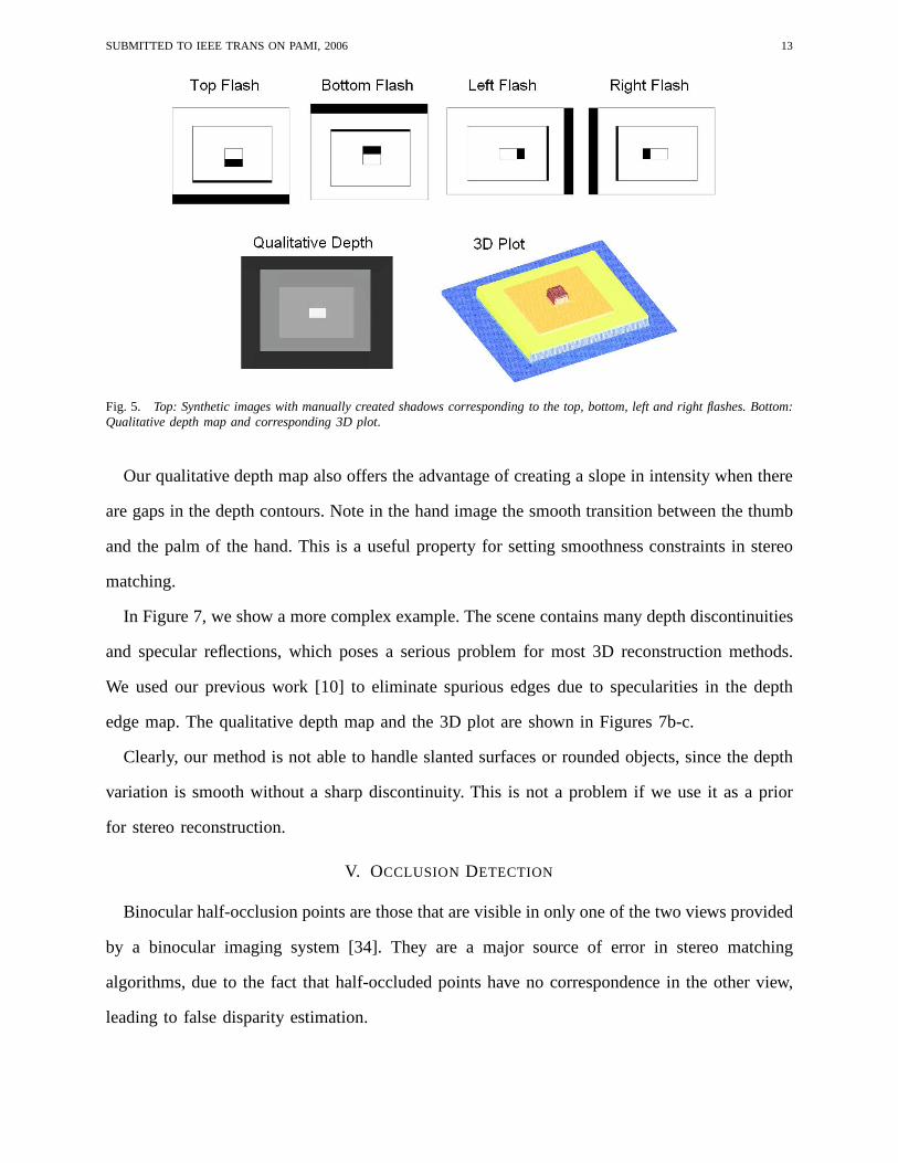
Figure 5 shows our qualitative depth map computation using synthetic images. We used as
input four images with manually created shadows corresponding to the top, bottom, left and
right flashes, as shown on the top of the figure. The resultant qualitative depth map, as well as
the correspondent 3D plot, are shown at the bottom of the figure. Note that the elevations of the
rectangular areas are proportional to the associated length of shadows in the images.
E. Real Images
Figure 6 illustrates results obtained for the qualitative depth map computation from real
images, using a single multi-flash camera. As we can see, our method effectively segments
the scene, encoding object relative distances through the shadow width information. Note that
the images have low intensity variation and small depth changes, a challenging scenario for most
3D reconstruction methods.
SUBMITTED TO IEEE TRANS ON PAMI, 2006 13
Fig. 5. Top: Synthetic images with manually created shadows corresponding to the top, bottom, left and right flashes. Bottom:Qualitative depth map and corresponding 3D plot.
Our qualitative depth map also offers the advantage of creating a slope in intensity when there
are gaps in the depth contours. Note in the hand image the smooth transition between the thumb
and the palm of the hand. This is a useful property for settingsmoothness constraints in stereo
matching.
In Figure 7, we show a more complex example. The scene contains many depth discontinuities
and specular reflections, which poses a serious problem for most 3D reconstruction methods.
We used our previous work [10] to eliminate spurious edges due to specularities in the depth
edge map. The qualitative depth map and the 3D plot are shown in Figures 7b-c.
Clearly, our method is not able to handle slanted surfaces orrounded objects, since the depth
variation is smooth without a sharp discontinuity. This is not a problem if we use it as a prior
for stereo reconstruction.
V. OCCLUSION DETECTION
Binocular half-occlusion points are those that are visiblein only one of the two views provided
by a binocular imaging system [34]. They are a major source oferror in stereo matching
algorithms, due to the fact that half-occluded points have no correspondence in the other view,
leading to false disparity estimation.

SUBMITTED TO IEEE TRANS ON PAMI, 2006 14
Fig. 6. From left to right: original image, qualitative depth map and the corresponding 3D plot. Note that our method capturessmall changes in depth and is robust in the presence of low intensity variations across depth contours.
Fig. 7. (a) Complex scene with many depth discontinuities and specular reflections. (b) Qualitative depth map. (c) Corresponding3D plot.

SUBMITTED TO IEEE TRANS ON PAMI, 2006 15
Current approaches to detect occlusion points are passive (see [34] for a comparison among
five different techniques). They rely on the correspondenceproblem and thus are unable to
produce accurate results for many real scenes. In general, these methods report a high rate of
false positives and have problems to detect occlusions in areas of the scene dominated by low
spatial frequency structure.
A. Occlusions Bounded by Shadows
Rather than relying on the hard correspondence problem, we exploit active lighting to detect
binocular half-occlusions. Assume we have a stereo pair of multi-flash cameras with horizontal
parallax and light sources arranged as Figure 8. By placing the light sources close to the center of
projection of each camera, we can use the length of the shadows created by the lights surrounding
the other camera to bound the half-occluded regions.
This idea is illustrated in Figure 8. Note that the half-occluded regionS is bounded by the
width of the shadowsS1 andS2. Observing the figure, letIL1, IR1
andIR2be the images taken
by the left camera with light sourcesFL1, FR1
andFR2, respectively. The width ofS1 andS2
can be determined by applying the meanshift segmentation algorithm in the ratio imagesIR1
IL1
and
IR2
IL1
(as described in section IV-A). We then determine the half-occluded region by averaging the
shadowed regions:S = BB1+B2
(S1 + S2), whereB, B1, andB2 are the baselines of the camera
and each light source, as shown in the figure.
The occluded region is determined with precision for planarshadowed region and with close
approximation for non-planar shadowed region. In the non-planar case, the linear relationship
between baseline and shadow width does not hold, but the length of the occluded region is
guaranteed to be bounded by the shadows.
We used two Canon G3 cameras with light sources arranged as Figure 8 to test our half-
occlusion detection algorithm. Figure 9 demonstrates the reliable performance of our method. The
images contain occlusion points in both textured and textureless regions, which is a challenging
problem for passive algorithms that rely on pixel correspondence. For quantitative evaluation, we
selected a piecewise planar scene (Figure 9a-c), since it iseasier to obtain the occlusion ground

SUBMITTED TO IEEE TRANS ON PAMI, 2006 16
Fig. 8. The length of the half-occluded regionS is bounded by shadowsS1 and S2 created by flashes surrounding the othercamera.
truth (computed from the known disparity map). For this scene, our method reports0.65% of
false positives and0.12% of false negatives. The false positives rate is given by the number of
false alarm occluded pixels divided by the total number of detected occluded pixels. The false
negative rate is given by the number of false negative occluded pixels divided by the number of
ground truth occluded pixels. For very large depth differences our method may not give a precise
estimation (for non-planar shadowed regions, due to largerbounded regions) and it might fail
due to detached shadows with thin objects.
VI. ENHANCED STEREO MATCHING
In this section, we use our feature maps as prior informationto enhance stereo matching
algorithms. We start by demonstrating an enhanced window-based, local stereo method that
takes advantage of depth edges and occlusions to produce disparity maps with very few com-
putations and much more accuracy than traditional correlation-based methods. Then, we show
how to incorporate our feature maps into global stereo methods based on Markov random field
optimization. We also analyse different stereo implementation setups and scenes with specular

SUBMITTED TO IEEE TRANS ON PAMI, 2006 17
Fig. 9. Detection of binocular half-occlusions in both textured and textureless regions. (a)-(b) Images taken with light sourcessurrounding the other camera. (c) Our occlusion detection result marked as white pixels.0.65% false positives and0.12% falsenegatives were reported. (d) Left view. (e) Right view. (f) Occlusion detection (white pixels).
reflections. Finally, we discuss limitations of our technique and compare with previous 3D
reconstruction approaches.
A. Enhanced Local Stereo
A major challenge in local stereo is to produce accurate results near depth discontinuities. In
such regions, the main assumption of local methods is violated: the same window (aggregation
support) contains pixels that significantly differ in disparity, often causing serious errors in
the matching process, due to perspective distortions. In addition, windows that include half-
occluded points near depth discontinuities are another source of error, since they do not have
correspondence in the other view.
The central problem of local methods is to determine the optimal size, shape, and weight
distribution of the aggregation support for each pixel. There is a trade-off in choosing the window
size: if the window is too small, a wrong match might be found due to ambiguities and noise. If
the window is too large, problems due to foreshortening and depth discontinuities occur, with the
result of lost detail and blurring of object boundaries. Previous solutions to this problem include
the use of adaptive windows [12] and shiftable windows [13],but producing clean results around
depth discontinuities still remains a challenge.

SUBMITTED TO IEEE TRANS ON PAMI, 2006 18
1) Varying Window Size and Shape:We adopt a sliding window which varies in shape and
size, according to depth edges and occlusion, to perform local correlation. Given the quality of
the detection of depth edges and half-occluded points, results are significantly improved.
In order to determine the size and shape of the window for eachpixel, we determine the set
of pixels that has aproximately the same disparity as the center pixel of the window. This is
achieved by a region growing algorithm (starting at the center pixel) which uses depth edges
and half-occluded points as boundaries.
Only this set of pixels is then used for matching in the other view. The other pixels in the
window are not considered, since they correspond to a different disparity.
2) Experiments:We first demonstrate the usefulness of depth edges in local stereo using
the 640x480 Tsukuba stereo pair of the Middlebury dataset (http://www.middlebury.edu/stereo).
Figure 10a shows one of the stereo input images. The disparity ground truth for each pixel is
shown in Figure 10b and the depth edge map computed from the ground truth is shown in Figure
10c. The results using a traditional correlation-based algorithm are shown in Figure 10d for a
window size of 9x9 pixels and Figure 10e for a window size of 31x31 pixels. The trade-off in
choosing the window size is clearly shown from these images:a smaller 9x9 window causes
noisy results, while a larger 31x31 window causes significant errors near depth discontinuities. In
order to verify the importance of depth edges in local stereo, we used our algorithm considering
as input the stereo pair and the depth edge map computed from the disparity ground truth.
Figures 10f and 10g show our results for 9x9 and 31x31 window sizes, respectively. Clearly, the
disparity map results are significantly improved near depthdiscontinuities. Note that this is a
synthetic example to illustrate the effect of depth discontinuities in stereo, since we are assuming
we have as input the depth edge map, which is difficult to obtain without active illumination.
Next we evaluate our method in a real scenario, using multi-flash imaging to compute depth
edges and occlusions. We used a horizontal slide bar for acquiring stereo images with a multi-
flash camera. Occlusions were estimated by moving the flashesproperly to the shooting camera
positions.

SUBMITTED TO IEEE TRANS ON PAMI, 2006 19
Fig. 10. (a) One image of the stereo pair. (b). Disparity map ground truth. (c) Depth edge map computed from the groundtruth. (d) Local correlation result with a 9x9 window. (e) Local correlation result with a 31x31 window. (f) Our enhancedlocalstereo result with a 9x9 window. (g) Our enhanced local stereo result with a 31x31 window.
Figure 11a shows one of the views of a difficult scene we used asinput. The image contains
textureless regions, ambiguous patterns (e.g., the background close to the book), a geometrically
complex object and thin structures. The resolution of the images is 640x480. We rectified them so
that epipolar lines are aligned with horizontal scanlines.We adopted a small baseline between the
cameras (maximum disparity equals 10), so that we can obtaina hand-labeled disparity ground
truth (Figure 11b).
Figure 11c shows our computed depth edges and half-occludedpoints. Note that some edges
do not appear in the ground truth (due to range resolution) and we also have some gaps in the
edges due to noise. This data was considered to test our algorithms under noisy conditions.
Traditional local-correlation approaches perform very poorly in this scene, as we show in
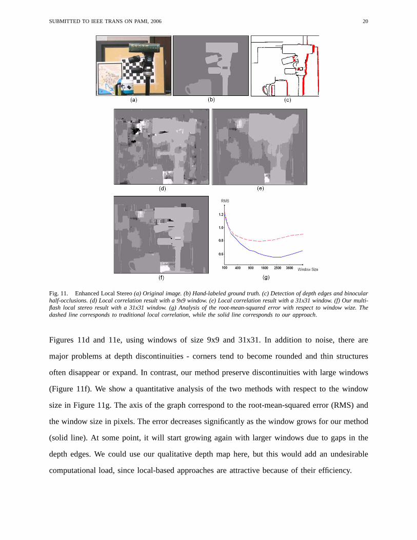
SUBMITTED TO IEEE TRANS ON PAMI, 2006 20
Fig. 11. Enhanced Local Stereo(a) Original image. (b) Hand-labeled ground truth. (c) Detection of depth edges and binocularhalf-occlusions. (d) Local correlation result with a 9x9 window. (e) Local correlation result with a 31x31 window. (f) Our multi-flash local stereo result with a 31x31 window. (g) Analysis ofthe root-mean-squared error with respect to window wize. Thedashed line corresponds to traditional local correlation,while the solid line corresponds to our approach.
Figures 11d and 11e, using windows of size 9x9 and 31x31. In addition to noise, there are
major problems at depth discontinuities - corners tend to become rounded and thin structures
often disappear or expand. In contrast, our method preservediscontinuities with large windows
(Figure 11f). We show a quantitative analysis of the two methods with respect to the window
size in Figure 11g. The axis of the graph correspond to the root-mean-squared error (RMS) and
the window size in pixels. The error decreases significantlyas the window grows for our method
(solid line). At some point, it will start growing again withlarger windows due to gaps in the
depth edges. We could use our qualitative depth map here, butthis would add an undesirable
computational load, since local-based approaches are attractive because of their efficiency.
SUBMITTED TO IEEE TRANS ON PAMI, 2006 21
B. Enhanced Global Stereo
The best results achieved in stereo matching thus far are given by global stereo methods,
particularly those based on belief propagation and graph cuts [19], [18]. These methods formulate
the stereo matching problem as a maximum a posteriori MarkovRandom Field (MRF) problem.
In this section, we will describe our enhanced global stereomethod, which uses belief propagation
for inference in the Markov network.
Some current approaches explicitly model occlusions and discontinuities in the disparity com-
putation [35], [36], but they rely on intensity edges and junctions as cues for depth discontinuities.
This poses a problem in low-contrast scenes and in images where object boundaries appear
blurred. However, we want to suppress smoothness constraints only at occluding edges, not at
texture or illumination edges. Our method makes use of the prior information to circumvent
these problems, including the qualitative depth map and theautomatically detected binocular
half-occlusions described earlier.
1) Inference by Belief Propagation:The stereo matching problem can be formulated as a
MRF with hidden variables{xs}, corresponding to the disparity of each pixel, and observed
variables{ys}, corresponding to the matching cost (often based on intensity differences) at
specific disparities. By denotingX = {xs} and Y = {ys}, the posteriorP (X|Y ) can be
factorized as:
P (X|Y ) ∝∏
s
ψs(xs, ys)∏
s
∏
t∈N(s)
ψst(xs, xt) (6)
whereN(s) represents a neighborhood ofs, ψst is called the compatibility matrix between nodes
xs andxt (smoothness term), andψs(xs, ys) is called the local evidence for nodexs, which is the
observation probabilityp(ys|xs) (data term). The belief propagation algorithm gives an efficient
approximate solution in this Markov network. We refer the reader to [18] for details about the
derivation of equation (6) and the inference based on beliefpropagation.
2) Qualitative Depth as Evidence:We can potentially use our computed depth edges to
suppress smoothness constraints during optimization. However, the depth contours may have
gaps. Fortunately, our qualitative depth image shows a desirable slope in intensity when gaps
SUBMITTED TO IEEE TRANS ON PAMI, 2006 22
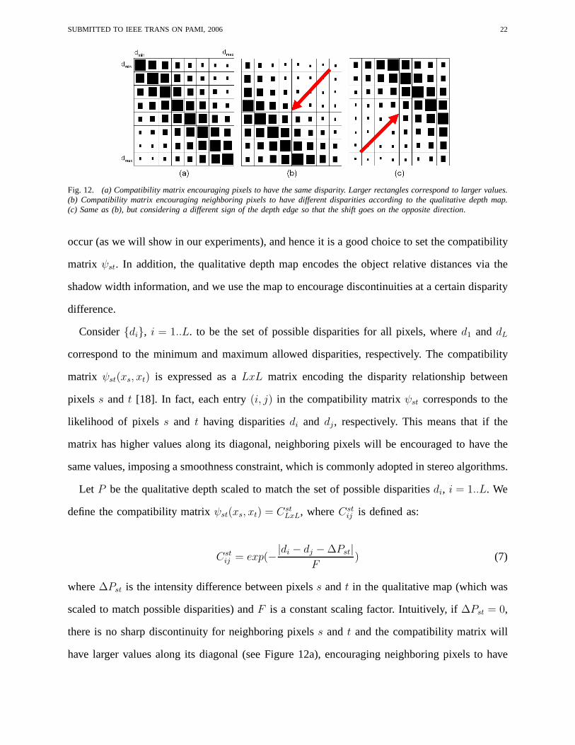
Fig. 12. (a) Compatibility matrix encouraging pixels to have the same disparity. Larger rectangles correspond to larger values.(b) Compatibility matrix encouraging neighboring pixels to have different disparities according to the qualitative depth map.(c) Same as (b), but considering a different sign of the depthedge so that the shift goes on the opposite direction.
occur (as we will show in our experiments), and hence it is a good choice to set the compatibility
matrix ψst. In addition, the qualitative depth map encodes the object relative distances via the
shadow width information, and we use the map to encourage discontinuities at a certain disparity
difference.
Consider{di}, i = 1..L. to be the set of possible disparities for all pixels, whered1 anddL
correspond to the minimum and maximum allowed disparities,respectively. The compatibility
matrix ψst(xs, xt) is expressed as aLxL matrix encoding the disparity relationship between
pixels s and t [18]. In fact, each entry(i, j) in the compatibility matrixψst corresponds to the
likelihood of pixelss and t having disparitiesdi and dj, respectively. This means that if the
matrix has higher values along its diagonal, neighboring pixels will be encouraged to have the
same values, imposing a smoothness constraint, which is commonly adopted in stereo algorithms.
Let P be the qualitative depth scaled to match the set of possible disparitiesdi, i = 1..L. We
define the compatibility matrixψst(xs, xt) = CstLxL, whereCst
ij is defined as:
Cstij = exp(−
|di − dj − ∆Pst|
F) (7)
where∆Pst is the intensity difference between pixelss andt in the qualitative map (which was
scaled to match possible disparities) andF is a constant scaling factor. Intuitively, if∆Pst = 0,
there is no sharp discontinuity for neighboring pixelss and t and the compatibility matrix will
have larger values along its diagonal (see Figure 12a), encouraging neighboring pixels to have

SUBMITTED TO IEEE TRANS ON PAMI, 2006 23
Fig. 13. (a) Standard belief propagation result. (b) Our enhanced global stereo method, given the knowledge of depthdiscontinuities.
the same disparity. In contrast, if∆Pst 6= 0, the larger values will be shifted to the disparity
encoded by∆Pst (see Figures 12b-c). The direction of this shift depends on the sign of∆Pst,
which is the sign of the corresponding depth edge.
We have also included the half-occlusion information in ourmethod. Nodes corresponding to
pixels that have no match in the other view are eliminated, while a penalty is given for matching
a given pixel with an occluded point in the other view.
3) Experiments:Figure 13 shows a comparison of our algorithm with traditional global stereo
based on belief propagation. As before, we used the input images from the Middlebury dataset
with depth edges computed from the disparity map ground truth. For this example, we have not
used the information from occlusions and qualitative depth; we just used depth edges to stop
smoothness constraints in the energy function. As we can see, results are considerably improved
near depth discontinuities.
The computed qualitative map in our challenging stereo example is shown in Figure 14a. The
results for the standard belief propagation algorithm and our enhanced method are shown in
Figures 14b and 14c, respectively. The passive method failsto preserve discontinuities due to
matching ambiguities (we used the implementation available at http://cat.middlebury.edu/stereo/
with different weight and penalty parameters). Black pixels mean noisy values (zero disparity).
Our results clearly show significant improvements with a RMSof 0.4590 compared to 0.9589
for this input. It is important to note that (although we do not show in this scene) our method
handles slanted surfaces in exactly the same way as standardglobal methods. In other words,

SUBMITTED TO IEEE TRANS ON PAMI, 2006 24
Fig. 14. Enhanced Global Stereo(a) Qualitative depth map. (b) Standard passive belief propagation result (RMS: 0.9589).(c) Our enhanced global stereo method (RMS: 0.4590).
we do not sacrifice slanted surfaces to preserve discontinuities as opposed to [16].
C. Specular Scenes
Specularities pose a problem for stereo matching, since they are viewpoint dependent and can
cause large intensity differences at corresponding points. With multi-flash imaging, as shown in
our previous work [10], we can significantly reduce the effect of specular reflections in images,
thus enhancing stereo correspondence near specular regions.
We used the setup shown in Figure 2d to capture four image pairs of a specular scene under
different lighting conditions. Figures 15a and 15b show thestereo pair (left view and right view,
respectively), captured with one single shot, using the flash positioned to the right of the camera.
Note how specularities are different in the two views.
Using the remaining flash images, we can attenuate the effectof specular reflections with our
gradient-domain method described in previous work [10]. The specular-reduced image pair is
SUBMITTED TO IEEE TRANS ON PAMI, 2006 25
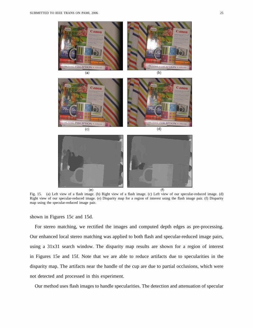
Fig. 15. (a) Left view of a flash image. (b) Right view of a flash image. (c) Left view of our specular-reduced image. (d)Right view of our specular-reduced image. (e) Disparity mapfor a region of interest using the flash image pair. (f) Disparitymap using the specular-reduced image pair.
shown in Figures 15c and 15d.
For stereo matching, we rectified the images and computed depth edges as pre-processing.
Our enhanced local stereo matching was applied to both flash and specular-reduced image pairs,
using a 31x31 search window. The disparity map results are shown for a region of interest
in Figures 15e and 15f. Note that we are able to reduce artifacts due to specularities in the
disparity map. The artifacts near the handle of the cup are due to partial occlusions, which were
not detected and processed in this experiment.
Our method uses flash images to handle specularities. The detection and attenuation of specular

SUBMITTED TO IEEE TRANS ON PAMI, 2006 26
reflections in ambient (no-flash) images has been recently addressed by Agrawal et al. [37], using
flash and no-flash image pairs. The advantage of using flash images is that they are less noisy
and more appropriate for dark environments.
When specular boundaries overlap in most images, we are not able to remove specularities.
This is the reason why we still have some specular artifacts in Figure 15f.
D. Efficiency
Our qualitative depth map takes about two seconds to computeon a Pentium IV 1.8 GHz
for 640x480 resolution images. Our enhanced local-based stereo algorithm requires very few
computations since depth edges can be computed extremely fast [8]. Our enhanced global method
computation time is the sum of the time for the qualitative depth map computation plus the time
for belief propagation procedure. We refer to [38] for an efficient implementation of the belief
propagation algorithm.
VII. D ISCUSSION
In addition to the proposed methods described in the previous section, signed depth edges
could also be used as part of the matching cost computation. This would be very useful in
low-contrast scenes, where occluding boundaries may not correspond to intensity edges. The
disadvantage of matching depth edges is that problems may occur when a depth discontinuity
in one view corresponds to a surface normal discontinuity inthe other view.
Small baseline multi-flash illumination could be used to enhance multiple view stereo algo-
rithms for 3D object modeling [39], [40], [41]. We refer to the work of Crispell [42] along this
direction, which shows the importance of depth edges and multi-flash photography to reconstruct
objects with concavities. In our work, we applied our feature maps to aid the establishment of
point correspondences between two images acquired with a pair of small baseline cameras.
A. Comparison with other techniques
Table I shows a comparison of our multi-flash stereopsis approach with other stereo methods.
Note that a small baseline flash setup means we do not need a laboratory setup as in photometric

SUBMITTED TO IEEE TRANS ON PAMI, 2006 27
TABLE I
Comparison of our technique with other 3D reconstruction approaches.
stereo and the cost and complexity of a flash attachment is very low. In addition, for non-intrusive
applications, we can use readily available infra-red flash lighting, while projecting high frequency
structured patterns requires an infra-red projector.
Below we give a more detailed discussion of the pros and cons of our method compared with
stereo techniques:
1) Passive Stereo:As we showed in the previous section, our method significantly enhances
the establishment of point correspondences near depth discontinuities and specular highlights,
when compared to passive stereo methods. Both techniques will fail in large textureless regions.
Passive stereo methods are non-intrusive and more suitablefor processing dynamic scenes. In
outdoor scenarios, when sun light has more intensity than flash light, we can not enhance passive
stereo matching.
2) Stereo Based on Structured Light:Active stereo techniques based on structured lighting
produce more accurate correspondence maps than our approach. On the other hand, our method
offers advantages in terms of low cost, simplicity, and portability. In addition, our feature maps
could be used to enhance structured light techniques. Even state of the art 3D scanners may
SUBMITTED TO IEEE TRANS ON PAMI, 2006 28
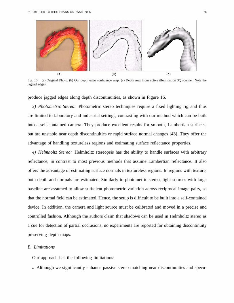
Fig. 16. (a) Original Photo. (b) Our depth edge confidence map. (c) Depth map from active illumination 3Q scanner. Note thejagged edges.
produce jagged edges along depth discontinuities, as shownin Figure 16.
3) Photometric Stereo:Photometric stereo techniques require a fixed lighting rig and thus
are limited to laboratory and industrial settings, contrasting with our method which can be built
into a self-contained camera. They produce excellent results for smooth, Lambertian surfaces,
but are unstable near depth discontinuities or rapid surface normal changes [43]. They offer the
advantage of handling textureless regions and estimating surface reflectance properties.
4) Helmholtz Stereo:Helmholtz stereopsis has the ability to handle surfaces with arbitrary
reflectance, in contrast to most previous methods that assume Lambertian reflectance. It also
offers the advantage of estimating surface normals in textureless regions. In regions with texture,
both depth and normals are estimated. Similarly to photometric stereo, light sources with large
baseline are assumed to allow sufficient photometric variation across reciprocal image pairs, so
that the normal field can be estimated. Hence, the setup is difficult to be built into a self-contained
device. In addition, the camera and light source must be calibrated and moved in a precise and
controlled fashion. Although the authors claim that shadows can be used in Helmholtz stereo as
a cue for detection of partial occlusions, no experiments are reported for obtaining discontinuity
preserving depth maps.
B. Limitations
Our approach has the following limitations:
• Although we significantly enhance passive stereo matching near discontinuities and specu-

SUBMITTED TO IEEE TRANS ON PAMI, 2006 29
larities, our method suffers from other well-known problems in passive matching, such as
handling textureless regions, noise, and non-Lambertian surface reflectance. Some of these
problems are addressed by active stereo approaches, as we mentioned in the last section. Our
feature maps obtained with small baseline illumination could be used to enhance these active
illumination stereo methods as well, as most of them are sensitive near depth discontinuities.
• Our method fails for outdoor scenarios when the sun’s illumination is more intense than
the flashes. In this case, depth edges and occlusions can not be detected and used as prior
information in stereo. For local stereo, our algorithm would be equivalent to traditional
correlation-based approaches, since the window shape and size would keep constant along
the image. For global stereo, we would have to use intensity edges in addition to the
qualitative depth map to set smoothness constraints.
• When thin foreground objects are present in the scene, we mayhave problems with detached
shadows that are separated from the object. In our previous work [44], we have exploited
a multi-baseline approach (one camera with multiple flashescovering multiple baselines)
to handle this issue. We believe that detached shadows couldalso be used as a positive
source of information. For example, it could be used to handle ordering constraintsin
stereo based on dynamic programming. In fact, the ordering assumption is often violated
when thin foreground objects are present in the scene.
• Motion is another cause of failure in our approach, since multiple images are taken sequen-
tially. Without proper image registration, our feature maps can not be computed reliably. A
possible solution to this problem is the use of light sourceswith variable wavelength [44],
which can be triggered at the same time to create shadows withdifferent colors.
VIII. C ONCLUSIONS
We have presented a set of techniques based on active lighting for reliable, discontinuity
preserving stereo matching. Our methods include the derivation of a qualitative depth map from
one single camera, detection of binocular half-occlusions, and enhanced local and global stereo
algorithms based on these features.
SUBMITTED TO IEEE TRANS ON PAMI, 2006 30
Our techniques are reliable, simple, and inexpensive; the overall setup can be built into a
self-contained device, no larger than existing 3D cameras.In the future, we plan to extend our
multi-flash imaging framework to handle the general problemof classification of discontinu-
ities according to their physical origin, i.e, discriminating discontinuities in depth, reflectance,
illumination and surface normal.
REFERENCES
[1] D. Scharstein and R. Szeliski. A taxonomy and evaluationof dense two-frame stereo correspondence algorithms. InInternational Journal of Computer Vision, volume 47(1), pages 7–42, 2002.
[2] M.Bell and W. Freeman. Learning local evidence for shading and reflectance. InInternational Conference on ComputerVision (ICCV’01), volume 1, pages 670–677, 2001.
[3] L. Zhang, B. Curless, and S. Seitz. Rapid shape acquisition using color structured light and multi-pass dynamicprogramming. InInternational Symposium on 3D Data Processing Visualization and Transmission, pages 24–26, Padova,Italy, 2002.
[4] J. Davis, D. Nehab, R. Ramamoothi, and S. Rusinkiewicz. Spacetime stereo: a unifying framework for depth fromtriangulation. IEEE Transactions on Pattern Analysis and Machine Intelligence, 27(2), 2005.
[5] T. Zickler, P. Belhumeur, and D. Kriegman. Helmholtz stereopsis: Exploiting reciprocity for surface reconstruction. InEuropean Conference on Computer Vision (ECCV’02), 2002.
[6] A. Hertzmann and S. Seitz. Shape and materials by example: A photometric stereo approach. InConference on ComputerVision and Pattern Recognition (CVPR’03), pages 533–540, Madison,Wisconsin, 2003.
[7] M. Daum and G. Dudek. On 3-D Surface Reconstruction usingShape from Shadows. InConference on Computer Visionand Pattern Recognition (CVPR’98), pages 461–468, June 1998.
[8] R. Raskar, K. Tan, R. Feris, J. Yu, and M. Turk. A non-photorealistic camera: depth edge detection and stylized renderingusing multi-flash imaging.SIGGRAPH 2004 / ACM Transactions on Graphics, 2004.
[9] K. Tan, J. Kobler, P. Dietz, R. Feris, and R. Raskar. Shape-enhanced surgical visualizations and medical illustrations withmulti-flash imaging. InInternational Conference on Medical Imaging Computing andComputer Assisted Intervention(MICCAI’04), France, 2004.
[10] R. Feris, R. Raskar, k. Tan, and M. Turk. Specular reflection reduction with multi-flash imaging. InIEEE BrazilianSymposium on Computer Graphics and Image Processing (SIBGRAPI’04), Curitiba, Brazil, 2004.
[11] R. Feris, M. Turk, R. Raskar, K. Tan, and G. Ohashi. Exploiting depth discontinuities for vision-based fingerspellingrecognition. InIEEE Workshop on Real-time Vision for Human-Computer Interaction (in conjunction with CVPR’04),Washington DC, USA, 2004.
[12] T. Kanade and M. Okutomi. A stereo matching algorithm with an adaptive window: Theory and experiment.IEEETransactions on Pattern Analysis and Machine Intelligence, 16(9):920–932, 1994.
[13] S. Kang, R. Szeliski, and J. Chai. Handling occlusions in dense multi-view stereo. InConference on Computer Visionand Pattern Recognition (CVPR’01), volume 1, pages 102–110, 2001.
[14] P. Belhumeur and D. Mumford. A Bayesian treatment of thestereo correspondence problem using half-occluded regions.In Conference on Computer Vision and Pattern Recognition (CVPR’92), pages 506–512, Champaign, Illinois, 1992.
[15] S. Intille and A. Bobick. Disparity-space images and large occlusion stereo. InEuropean Conference on Computer Vision(ECCV’94), pages 179–186, 1994.
[16] S. Birchfield and C. Tomasi. Depth discontinuities by pixel-to-pixel stereo. International Journal of Computer Vision,35(3):269–293, 1999.
[17] M. Tappen and W. Freeman. Comparison of graph cuts with belief propagation for stereo, using identical MRF parameters.In International Conference on Computer Vision (ICCV’03), Nice, France, 2003.
[18] J. Sun, N. Zheng, and H. Shum. Stereo matching using belief propagation.IEEE Transactions on Pattern Analysis andMachine Intelligence, 25(07):787–800, 2003.
[19] V. Kolmogorov and R. Zabih. Computing visual correspondence with occlusions using graph cuts. InInternationalConference on Computer Vision (ICCV’01), Vancouver, Canada, 2001.
[20] J. Sun, S. Kang, and H. Shum. Symetric stereo matching for occlusion handling. InConference on Computer Vision andPattern Recognition (CVPR’05), San Diego, California, 2005.
[21] J. Salvi, J. Pages, and J. Batlle. Pattern codification strategies in structured light systems.Pattern Recognition, 37(4):827–849, 2004.
[22] D. Scharstein and R. Szeliski. High-accuracy stereo depth maps using structured light. InConference on Computer Visionand Pattern Recognition (CVPR’03), pages 195–202, Madison,Wisconsin, 2003.

SUBMITTED TO IEEE TRANS ON PAMI, 2006 31
[23] J. Posdamer and M. Altschuler. Surface measurement by space encoded projected beam systems.Computer Graphics andImage Processing, 18(1):1–17, 1982.
[24] E. Horn and N. Kiryati. Toward optimal structured lightpatterns.Image and Vision Computing, 17(2):87–97, 1999.[25] J. Tajima and M. Iwakawa. 3D data acquisition by rainbowrange finder. InInternational Conference on Pattern Recognition,
pages 309–313, 1990.[26] L. Zhang, N. Snavely, B. Curless, and S. Seitz. Spacetime faces: High-resolution capture for modeling and animation.
SIGGRAPH 2004 / ACM Transactions on Graphics, 2004.[27] R. Woodham. Photometric method for determining surface orientation from multiple images.Optical Engineering,
19(1):139–144, 1980.[28] S. Savarese, H. Rushmeier, F. Bernardini, and P. Perona. Shadow carving. InInternational Conference on Computer Vision
(ICCV’01), Vancouver, Canada, 2001.[29] J. Bouguet and P. Perona. 3D photography on your desk. InInternational Conference on Computer Vision (ICCV’98),
Bombay, India, 1998.[30] D. Yang. Shape from darkness under error. PhD thesis, Columbia University, 1996.[31] D. Kriegman and P. Belhumeur. What shadows reveal aboutobject structure.Journal of the Optical Society of America,
pages 1804–1813, 2001.[32] C. Christoudias, B. Georgescu, and Peter Meer. Synergism in low level vision. InInternational Conference on Pattern
Recognition, Quebec City, Canada, 2002.[33] R. Fattal, D. Lischinski, and M. Werman. Gradient domain high dynamic range compression. InSIGGRAPH 2002 / ACM
Transactions on Graphics, 2002.[34] G. Egnal and R. Wildes. Detecting binocular half-occlusions: Empirical comparisons of five approaches.IEEE Transactions
on Pattern Analysis and Machine Intelligence, 24(8):1127–1133, 2002.[35] M. Agrawal and L. Davis. Window-based, discontinuity preserving stereo. InConference on Computer Vision and Pattern
Recognition (CVPR’04), Washington, DC, 2004.[36] H. Ishikawa and D. Geiger. Occlusions, discontinuities, and epipolar lines in stereo. InEuropean Conference on Computer
Vision (ECCV’98), June 1998.[37] A. Agrawal, R. Raskar, S. Nayar, and Y. Li. Removing photography artifacts using gradient projection and flash-exposure
sampling.SIGGRAPH 2005 / ACM Transactions on Graphics, 2005.[38] P. Felzenszwalb and D. Huttenlocher. Efficient belief propagation for early vision. InConference on Computer Vision and
Pattern Recognition (CVPR’04), 2004.[39] W. Matusik, C. Buehler, R. Raskar, S. Gortler, and L. McMillan. Image-based visual hulls. InProceedings of SIGGRAPH
2000, pages 369–374, New Orleans, LA, 2000.[40] S. Seitz, B. Curless, J. Diebel, D. Scharstein, and R. Szeliski. A comparison and evaluation of multi-view stereo
reconstruction algorithms. InConference on Computer Vision and Pattern Recognition (CVPR’06), New York, NY, 2006.[41] R. Cipolla and P. Giblin.Visual Motion of Curves and Surfaces. Cambridge University Press, 2000.[42] D. Crispell, D. Lanman, P. Sibley, Y. Zhao, and G. Taubin. Beyond sillhouettes: Surface reconstruction using multi-flash
photography. InInternational Symposium on 3D Data Processing, Visualization and Transmission, 2006.[43] I. Sato, Y. Sato, and K. Ikeuchi. Stability issues in recovering illumination distribution from brightness in shadows. In
Conference on Computer Vision and Pattern Recognition (CVPR’01), pages 400–407, 2001.[44] R. Feris, M. Turk, and R. Raskar. Dealing with multi-scale depth changes and motion in depth edge detection. InIEEE
Brazilian Symposium on Computer Graphics and Image Processing (SIBGRAPI’06), Manaus, Brazil, 2006.