subpart o - machine guarding guarding presentation - 9... · where machine hazards occur: point of...
TRANSCRIPT

1
Subpart O - Machine
Guarding
Georgia Tech Research Institute
www.oshainfo.gatech.edu
We Will Cover:
Machine Guarding Principles
Subpart O - Highlights
Lockout/Tagout Overview
Employer Responsibilities
Why are machines not
guarded?
No one would stick their arm, hand, finger,
head, etc. in there.
No one is supposed to be back there, in
there, around it while it is running.
The machine came that way; it never had a
guard.
I’ve been doing it this way for twenty years
without any problems.

2
Why are machines not
guarded? (cont.)
The guard is in the way
The OSHA inspector didn’t say anything
about it.
We’ll put it back on if OSHA comes.
Emphasis on Amputations:
Where does it apply?
General industry employers whose
workplace include:
Shears
Saws
Slicers
Slitters
Power presses
(the 4s and a P)
Where machine hazards occur:
Point of operation
Mechanical power transmission
Other moving parts

3
Machine Guarding
Requirements
Prevent contact
Be secure
Protect from falling objects
Create no new hazards
No interference
Maintainability and accessibility
Machine Guarding
Requirements
Must NOT be able to reach
under, through, over or around the guards or otherwise access the hazard!
Any Hazards?

4
In-Running Nip Points
Belt and
pulley
Chain and
sprocketRack and
pinion
Rotating
cylinders
Methods of machine
safeguarding
Physical guards
Devices
Location/Distance
Guards v. Safeguarding
Devices
Fixed
Interlocked
Adjustable
Self-adjusting
Presence sensing
Pullback
Restraint
Safety controls and trips
Gates

5
Fixed Guard
Provides a barrier - a permanent part of the
machine, preferable to all other types of guards.

6
Interlocked Guard
When this type of guard is opened or removed,
the tripping mechanism and/or power
automatically shuts off or disengages, and the
machine cannot cycle or be started until the
guard is back in place.
Interlocked
guard on
revolving drum
Adjustable Guard
Provides a barrier which may be adjusted to
facilitate a variety of production operations.
Bandsaw blade
adjustable guard
Self-Adjusting Guard
Provides a barrier which moves according to the
size of the stock entering the danger area.
Circular table saw
self-adjusting guard

7
Safeguarding devices
Presence sensing
Pullback
Restraint
Safety controls and trips
Gates
Presence Sensing Device

8
Pullbacks and Restraints
Pullback
device
Adjustable
wrist
straps
9
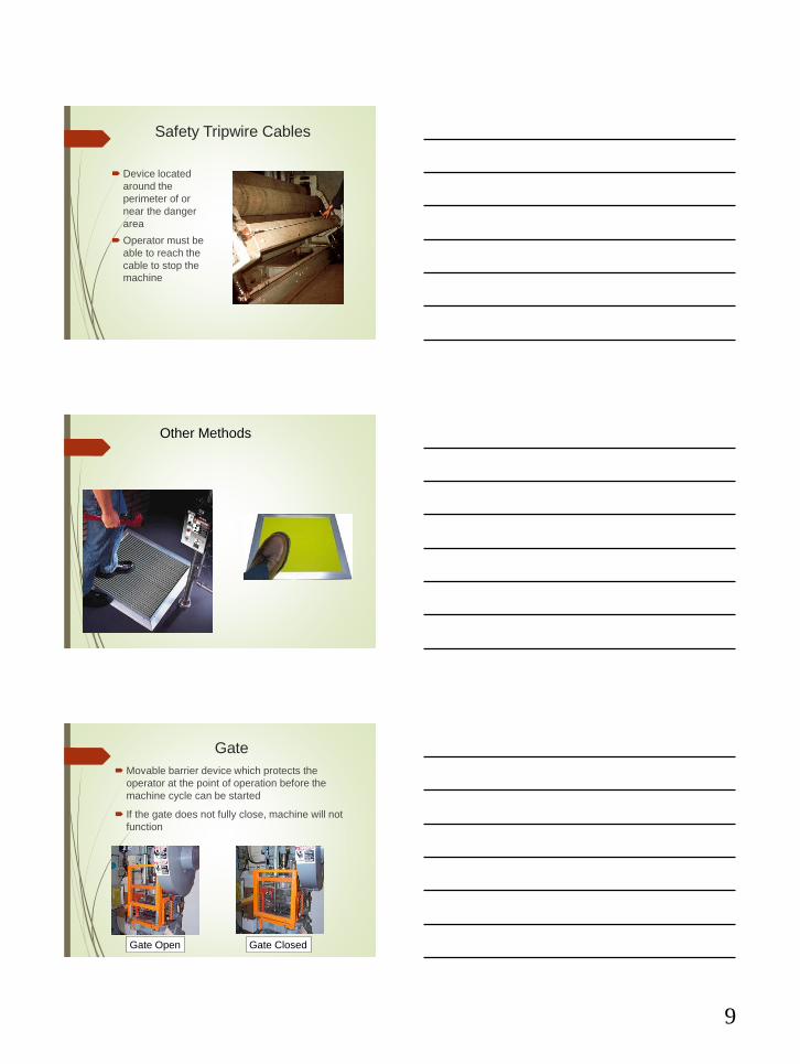
Safety Tripwire Cables
Device located
around the
perimeter of or
near the danger
area
Operator must be
able to reach the
cable to stop the
machine
Other Methods
Gate
Movable barrier device which protects the
operator at the point of operation before the
machine cycle can be started
If the gate does not fully close, machine will not
function
Gate Open Gate Closed

10
Safeguarding by Location/Distance
Locate the machine
or its dangerous
moving parts so
that they are not
accessible or do
not present a
hazard to a worker
during normal
operation
Maintain a safe
distance from the
danger area
Protective Shields
These do not give complete protection from
machine hazards, but do provide some protection
from flying particles, splashing cutting oils, or
coolants.
Robot Safety –
ANSI/RIA R15.06 2012

11
Fixed Guards (Pro vs. Con)
Many applications
Often built in-house
Can provide
maximum protection
Minimal maintenance
Suitable for high
production, repetitive
Can interfere with
visibility
Can be limited to
specific operations
(e.g. where point of
operation access not
necessary)
Machine adjustment
and repair can require
removal, requiring
other protection of
maintenance
Interlocked Guard (Pro vs.
Con)
Can provide
maximum
protection
Allows access for
removing jams
without time-
consuming removal
of guards (subject
to lockout
requirements)
Requires careful
adjustment and
maintenance
May be easy to
disengage or
defeat
Presence Sensing (Pro vs.
Con)
Can allow more
movement for
operator into point
of operation
Limited to
machines that can
be stopped
Does not protect
against flying
objects
May require
frequent alignment
and calibration

12
Pullbacks/Restraints (Pro vs.
Con)
Eliminates need for
additional guarding
Smaller risk of
mechanical failure
for restraints
Limits movement of
operator
May obstruct work space
around operator
Adjustments must be made
for each operation and
individual
Requires frequent
inspections and
maintenance
Requires close supervision
of the operator
2-Hand Control (Pro vs. Con)
Operators hands at
a predetermined
location (if controls
fixed)
Operators hands
free to pick up
parts
Requires partial
cycle machine with
a brake
Some 2-hand
controls can be
defeated
Protects only the
operator
Guarded????

13
Guarded????
Guarded????
Guarded?????

14
Subpart O - Machinery and
Machine Guarding
211 - Definitions
212 - General requirements
213 - Woodworking machinery
215 - Abrasive wheel machinery
216 - Mills and calendars
217 - Mechanical power presses
218 - Forging machines
219 - Mechanical power transmission
1910.212
General Requirements for all Machines
1910.212(a)(1)
One or more methods of machine guarding
shall be provided to protect the operator and
other employees in the machine area from
hazards such as those created by the point
of operation, in-going nip points, rotating
parts, flying chips and sparks.

15
1910.212(a)(3)(ii)
The point of operation of machines whose
operation exposes an employee to injury,
shall be guarded.
Point of Operation Guarded??
Point of Operation Guarding

16
Hand Tools
1910.212(a)(5)
When the periphery of the blades of a fan is
less than seven (7) feet above the floor or
working level, the blades shall be guarded.
The guard shall have openings no larger
than 1/2 inch.

17
1910.212(b)
Machines designed for a fixed location shall
be securely anchored to prevent walking or
moving.
1910.213
Woodworking Machinery Requirements
(Covered Later)
1910.215
Abrasive-Wheel Machinery

18
1910.215(a)(4)
Work rests shall be adjusted closely to the
wheel with a maximum opening of one-
eighth inch to prevent the work from being
jammed between the wheel and the rest,
which may cause wheel breakage.
Work Rest
1910.215(b)(9)
The distance between the wheel periphery and
the adjustable tongue or the end of the
peripheral member at the top shall never
exceed one-fourth inch.
Tongue Guard
1910.215(d)(1)
Immediately before mounting, all wheels
shall be closely inspected and sounded by
the user (ring test) to make sure they have
not been damaged.

19
Tech Guide –
www.oshainfo.gatech.edu

20
1910.217Mechanical Power Presses
What is a mechanical power
press?
Mechanical Power Presses
Mechanical Full Revolution Clutch
Can not be disengaged during full stroke
Mechanical Part Revolution Clutch
Can be disengaged at any time during a full
stroke
Guarding is dependent on which type of press
Example – Presence sensing devices or two
hand controls can’t guard a full revolution –
the stroke can’t be disengaged when device
is activated

21
1910.217(c)(1)
Use of point of operation guards or properly
applied and adjusted point of operation
devices on every operation performed on a
mechanical power press. See Table O-10.
Mechanical Power Presses
Periodic and regular inspections
Foot pedal protected to prevent unintended
operation
Machine Guarding power transmission
apparatus same as other equipment
The employer must report all point-of-
operation injuries within 30 days of
occurrence

22
1910.219
Mechanical Power-Transmission Apparatus
1910.219(b)(1)
Flywheels located so that any part is 7 feet
or less above the floor or platform shall be
guarded.
Wherever flywheels are above working
areas, guards shall be installed having
sufficient strength to hold the weight of the
flywheel in the event of a shaft or wheel
mounting failure.
1910.219(c)
Horizontal, vertical, and inclined shafting
must be enclosed.
Projecting shaft ends shall present a smooth
edge and end and shall not project more
than 1/2 the diameter of the shaft unless
guarded by non rotating cap or safety
sleeves.

23
1910.219(d)
Pulleys 7ft. or less above the floor or
platform must be guarded.
Pulleys with cracks or pieces broken out of
rims shall not be used.

24

25
k
Portable Tools

26
Portable Power Tools - General
Safety Precautions
1910.242(a)
Employers responsibility
Safe condition of tools
Including personal tools
1910.242(b)
Compressed air not used for cleaning
except where reduced to less than 30
p.s.i. and only when effective chip
guarding and PPE.
Power Tools (cont.)
1910.243 (a)(1) –
Portable Circular Saws
Upper blade guard
Lower blade guard
Automatically
returns to starting
position

27
Power Tools (cont.)
1910.243(a)(3)
Portable belt sanding machines
Guard nip point where belt runs onto
pulley
Guard unused run of belt
Pneumatic Power Tools and
Hose
1910.243(b)
Tool Retainer – A tool retainer must be
installed on each piece of equipment
where ejection could result
Airhose – Hose and hose connections
must be designed for the pressure and
service to which they are subjected

28
83
HOSE
CLAMP
UNACCEPTABLE ACCEPTABLE
Pneumatic Tool Connections
Powered Abrasive Wheels
Flying fragments
PPE
Ring test – 1910.243(c)(5)(i)
Mounting
Follow manufacturer’s instructions

29
Abrasive Wheels (cont.)
Max RPM
Abrasive Wheels (cont.)
Start up
Not directly in front
Guards – 1910.243(c)(1) – (c)(4)
Protect from moving wheel surface
Protect from breaking wheel fragments
Exception – When work protects the
operator
Abrasive Wheels (cont.)
180 deg

30
Abrasive Wheels (cont.)
1910.243(c)(1)(i)
Exceptions
Wheels used within the work
2” or smaller in diameter
Cones, plugs, etc. where work offers
protections
Abrasive Wheels (cont.)
1910.243(c)(6) – Other exclusions
Natural sandstone wheels
Metal, wooden, cloth, or paper discs
having a layer of abrasive surface
Powder Actuated Tool
Cut-Away View

31
Powder Actuated Tools
1910.243(d)
Must meet requirements in ANSI A10.3-
1970
Operators and assistants must wear eye
protection
Head and face protection dependent on
working conditions
Powder Actuated Tools (Cont.)
Must have protective shield or guard at least
3 ½ inches in diameter.
Firing must be dependent on at least 2
separate and distinct operations.
Firing mechanism must prevent tool from
firing during loading, while preparing, if
dropped.
Fasteners/Charges Used in
Powder Actuated Tools
Concrete
Concrete/wood
wood
Specific size = Specific operation
Be sure to use the right size charge
with right size fastener

32
LITTLETON, Colo. -- A dental office X-ray reveals a four-inch nail embedded in the skull of Patrick Lawler, 23, which was removed at Littleton Adventist Hospital in suburban Denver. Lawler unknowingly shot himself with a nail gun Jan. 6 while working in Breckenridge, a ski resort town in the central Colorado mountains. The accident left Lawler with what he thought was a minor toothache and blurry vision. When painkillers and ice failed to stop the ache six days later, he went to a dental office where the nail was discovered. (01/14/05 AP Photo/The Family Dental Center via KUSA-TV via The Denver Post)
SEOUL, Korea -- The X-ray picture shows a 5-centimeter nail stuck in an unidentified South Korean patient's skull Thursday, Dec. 2, 2004. According to a Seoul hospital, doctors found the nail after the man came to the hospital, complaining about a severe headache. They speculate that the nail stuck in the man's head four years ago in an accident but the man didn't know about it. The nail was removed in a surgery last Saturday. (12/07/04 AP photo)
Questions?