subroutine linkage - edward bosworth€¦ · web viewsubroutine linkage we now begin discussion...
TRANSCRIPT
Subroutine Linkage
We now begin discussion of subroutine linkages for simple subroutines withoutlarge argument blocks.
With the mechanisms discussed in this lecture, one can use either global variablesor general purpose registers to pass addresses, values, and results.
As the textbook notes, subroutines may be written to facilitate repetitive tasks.Indeed, the “Wheeler Jump” (EDSAC, 1952) was developed for just this purpose.
Early operating systems began as collection of subroutines to facilitate handlingof input and output devices, mainly line printers.
When batch programming became common, the computer needed a control program to automate the processing of a sequence of jobs, read and processed one after another.
This control program was merged with a set of subroutines for Input/Output handling and
routines for standard mathematical functions to create the first operating system.
Subroutines and/or functions can be invoked for side effect only or in order to compute and return results. Many of the subroutines used in the book are called for side effect – to
manage print position on a page and issue a new page command when necessary.

Subroutine Linkage: Instructions
The language requires two instructions associated with subroutines: one to call the subroutine and one to effect a return from the subroutine.
Calling the subroutineThe instruction used is either BAL (Branch and Link) or BALR.
The format of the instruction is BAL Reg,Address
An example of such an instruction is BAL 8,P10PAGE
The first argument is a register number to be used for subroutine linkage. We explain this more fully in just a bit.
The second argument is the address of the first instruction in the subroutine. There areother standards for this argument, but this is the one that IBM uses.
Returning from the subroutineThis instruction is used to return from execution of the subroutine. It is an unconditionaljump to an address contained in the register.
The format of the instruction is BR RegAn example of such an instruction is BR 8

BAL and BALR
There are two forms of the Branch and Link instruction.
BAL Branch and Link
BALR Branch and Link, Register.
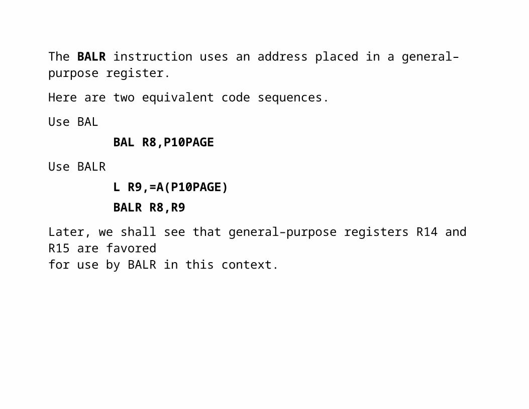
The difference lies in the handling of the entry point address of the called routine.The BALR instruction uses an address placed in a general–purpose register.
Here are two equivalent code sequences.
Use BAL BAL R8,P10PAGE
Use BALR L R9,=A(P10PAGE) BALR R8,R9
Later, we shall see that general–purpose registers R14 and R15 are favored for use by BALR in this context.

Comments on the Subroutine Linkage
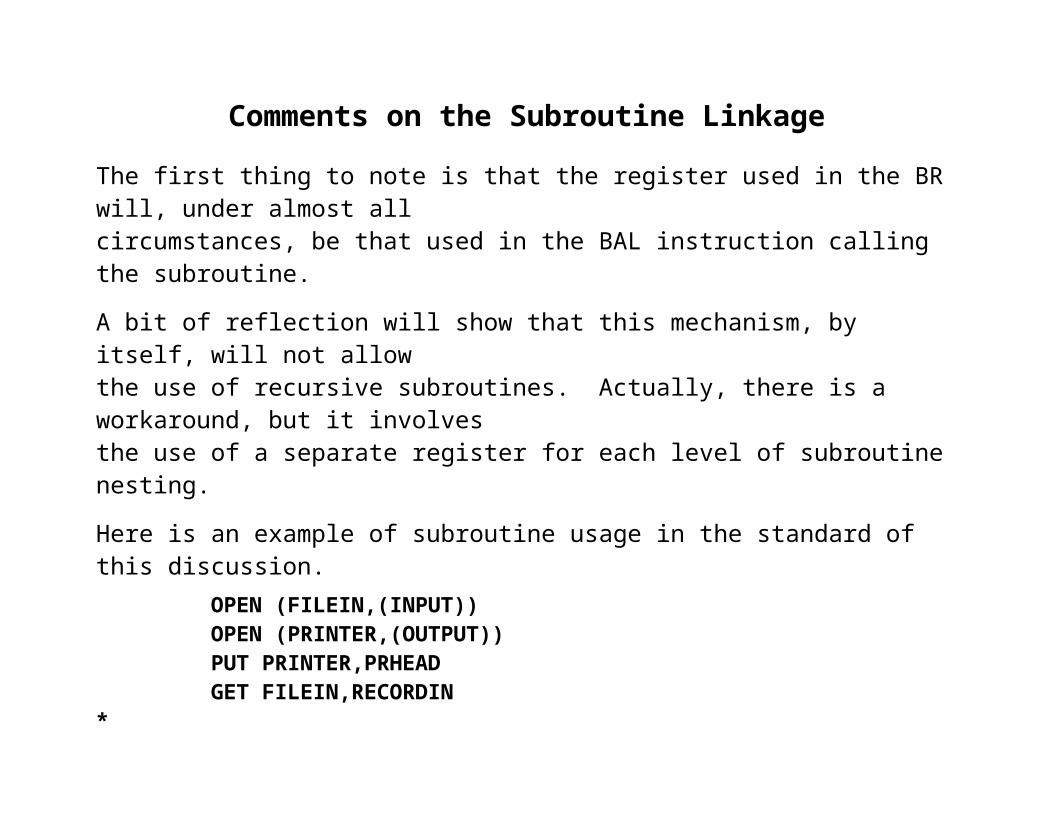
The first thing to note is that the register used in the BR will, under almost all circumstances, be that used in the BAL instruction calling the subroutine.
A bit of reflection will show that this mechanism, by itself, will not allow the use of recursive subroutines. Actually, there is a workaround, but it involvesthe use of a separate register for each level of subroutine nesting.
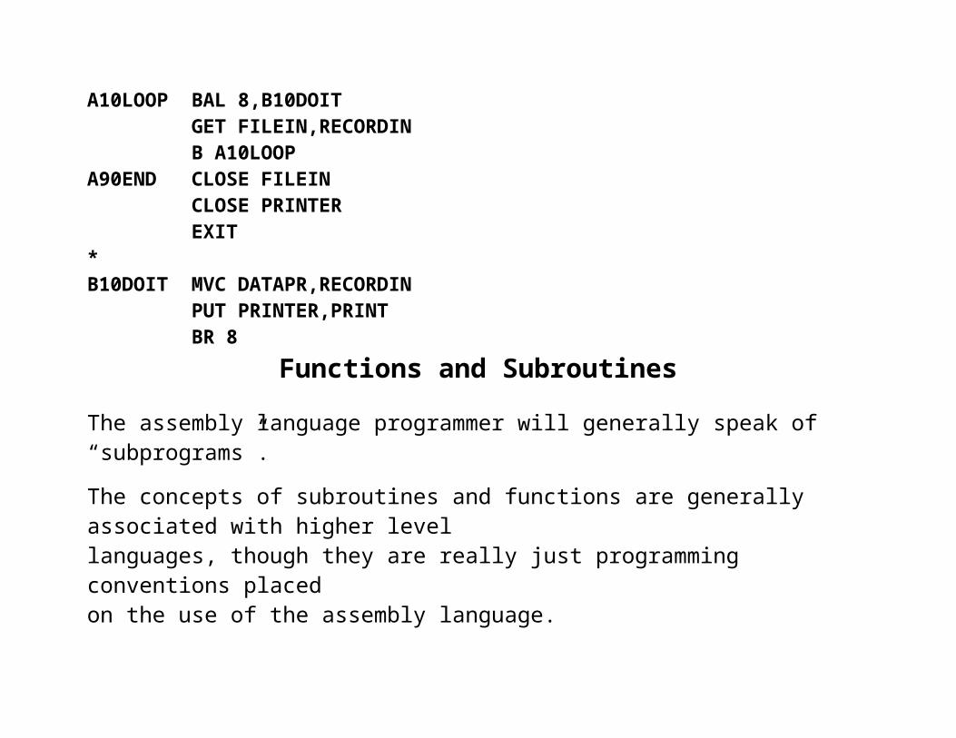
Here is an example of subroutine usage in the standard of this discussion. OPEN (FILEIN,(INPUT)) OPEN (PRINTER,(OUTPUT)) PUT PRINTER,PRHEAD GET FILEIN,RECORDIN * A10LOOP BAL 8,B10DOIT GET FILEIN,RECORDIN B A10LOOP A90END CLOSE FILEIN CLOSE PRINTER EXIT*B10DOIT MVC DATAPR,RECORDIN PUT PRINTER,PRINT BR 8
Functions and Subroutines
The assembly language programmer will generally speak of “subprograms”.
The concepts of subroutines and functions are generally associated with higher level languages, though they are really just programming conventions placed on the use of the assembly language.
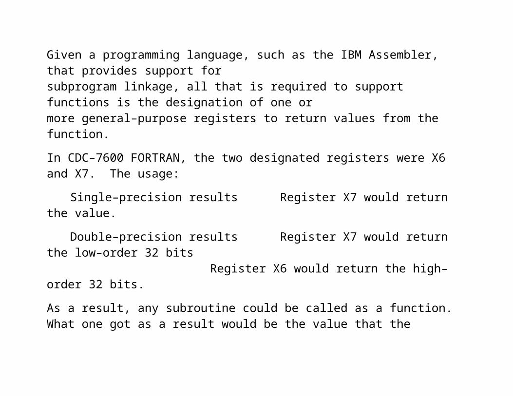
Given a programming language, such as the IBM Assembler, that provides support for subprogram linkage, all that is required to support functions is the designation of one or more general–purpose registers to return values from the function.
In CDC–7600 FORTRAN, the two designated registers were X6 and X7. The usage:
Single–precision results Register X7 would return the value.
Double–precision results Register X7 would return the low–order 32 bitsRegister X6 would return the high–order 32 bits.
As a result, any subroutine could be called as a function. What one got as a result would be the value that the subroutine last placed in X7 or both X6 and X7. While this was chancy, it was predictable.
Control Section: CSECT
A control section (CSECT) is, by definition, a block of coding that can be relocated within the computer address space without affecting the operating logic of the program.
A large system may comprise a number of control sections, each independently assembled and built using a link editor.
Every program contains a large number of references, either to variables or addresses.In a large system, individual control sections may contain references to variables or addresses not found locally. These are links to other control sections.
A link editor edits the links; it searches each CSECT for references that cannot be resolved locally and attempts to find matches in other CSECTS in the system.
As an example, suppose your HLL program contains the following line of code.Y = 100*SIN(X)
It is not likely that your program contains a function called SIN, presumably the sine.The linkage editor will find the appropriate function in the RTS library and resolve the reference by building the link from your program to the system routine.
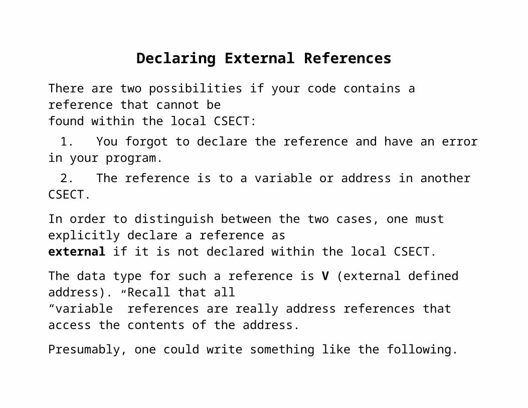
Declaring External References
There are two possibilities if your code contains a reference that cannot befound within the local CSECT:
1. You forgot to declare the reference and have an error in your program.2. The reference is to a variable or address in another CSECT.
In order to distinguish between the two cases, one must explicitly declare a reference as external if it is not declared within the local CSECT.
The data type for such a reference is V (external defined address). Recall that all “variable” references are really address references that access the contents of the address.
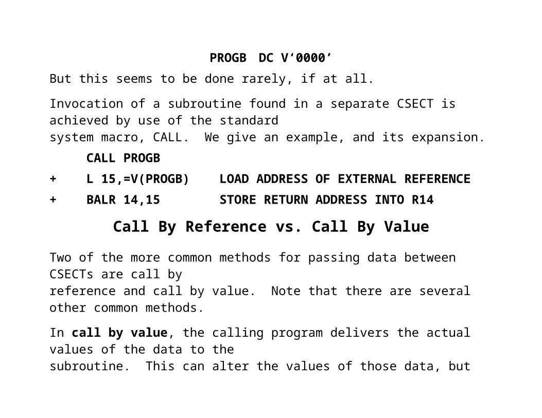
Presumably, one could write something like the following.PROGB DC V‘0000’
But this seems to be done rarely, if at all.
Invocation of a subroutine found in a separate CSECT is achieved by use of the standard system macro, CALL. We give an example, and its expansion. CALL PROGB+ L 15,=V(PROGB) LOAD ADDRESS OF EXTERNAL REFERENCE+ BALR 14,15 STORE RETURN ADDRESS INTO R14
Call By Reference vs. Call By Value
Two of the more common methods for passing data between CSECTs are call by reference and call by value. Note that there are several other common methods.
In call by value, the calling program delivers the actual values of the data to the subroutine. This can alter the values of those data, but the altered values will not be returned to the calling routine. Some languages call these “in parameters”.
In call by reference, the calling program delivers the addresses of the data items to the subroutine. The values of these data can be changed by the called subroutine and those values propagated back to the calling program.
Note that the return address for the subroutine can also be changed.This is an old hacker trick.
The next question we must ask is how these values and/or addresseswill be passed to the subroutine.

Mechanisms for Passing
By this title, we mean either the passing of values or the passing of addresses.
Basically, there are three mechanisms for passing values to a subroutine.Each of these has been used.
1. Pass the values in registers specifically designated for the purpose.2. Pass the values on the stack.3. Pass the values in an area of memory and pass a pointer to that area
by one of the other methods.
Remember that a pointer is really just an address in memory; it is an unsigned integer.
In some high–level languages, a pointer may be manipulated as if it were an unsigned integer (which it is). In others, standard arithmetic cannot be applied to pointers.
Languages, such as Java and C#, provide for pointers but do not allow direct arithmetic manipulation of these addresses. For that reason, the term “pointer” is not used.

Subroutines, Separate Assemblies and Linkage
The first example of a subroutine was the B10DOIT routine a few slides back.
B10DOIT MVC DATAPR,RECORDIN PUT PRINTER,PRINT BR 8
While this is a valid subroutine, we note two facts of importance.1. It is in the same assembly as the calling module.2. It is in the same CSECT as the calling module.
In general, we would like to link modules that are not assembled at the same time.
It might even be necessary to link assembled code with code written in a higher–levellanguage and compiled. Thus COBOL programs might call assembler language routines.
We have already encountered the external declaration, which is used to declare that:1. A label corresponds to an address declared in another module, and2. The linking loader will have to resolve that address by loading the called module,
assigning an address to this label, and updating that reference in the calling code.
IBM has established a set of conventions for use by all modules when calling separately assembled modules. These insure that each module can work with any other module.

The Save Areas
One key design feature when developing subroutines and functions is the minimization of side effects. One particular requirement concerns the general purpose registers.
This design requirement is that after the return from a called subprogram, the contents of the general purpose registers be exactly the same as before the call.
The only exception to this rule is the use of a general purpose register for the return of a function value. In this case, each of the calling routine and the called routine explicitly allows for the value of that one specified register to be changed.
Save and RestoreThe strategy used is that each routine (including the main program) will save the contents
of all but one of the general purpose registers on entry and restore those on exit.
This has evolved from an earlier strategy in which a developer would save the contents of
only those registers to be used explicitly in the subprogram.
In the statically allocated, non–recursive world of IBM assembler programs, each routine will declare an 18–fullword “save area”, used to save important data.
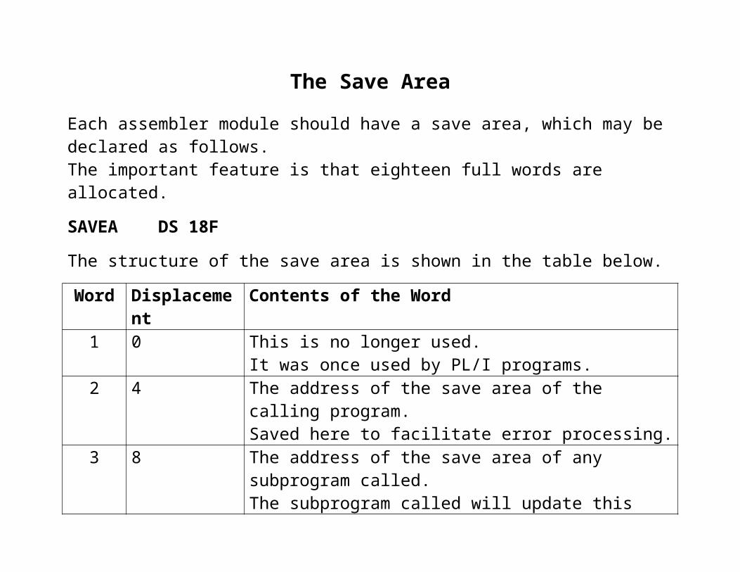
The Save Area
Each assembler module should have a save area, which may be declared as follows.The important feature is that eighteen full words are allocated.
SAVEA DS 18F
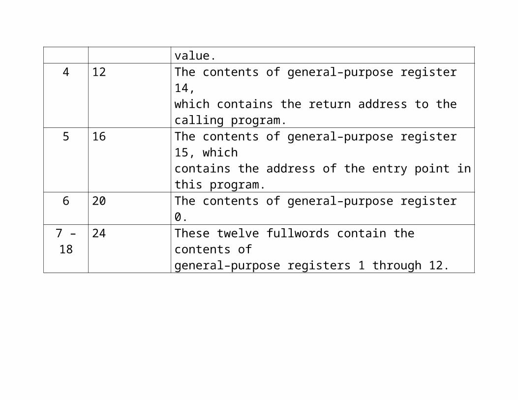
The structure of the save area is shown in the table below.
Word Displacement Contents of the Word1 0 This is no longer used.
It was once used by PL/I programs.2 4 The address of the save area of the calling program.
Saved here to facilitate error processing.3 8 The address of the save area of any subprogram called.
The subprogram called will update this value.4 12 The contents of general–purpose register 14,
which contains the return address to the calling program.5 16 The contents of general–purpose register 15, which
contains the address of the entry point in this program.6 20 The contents of general–purpose register 0.
7 – 18 24 These twelve fullwords contain the contents of general–purpose registers 1 through 12.
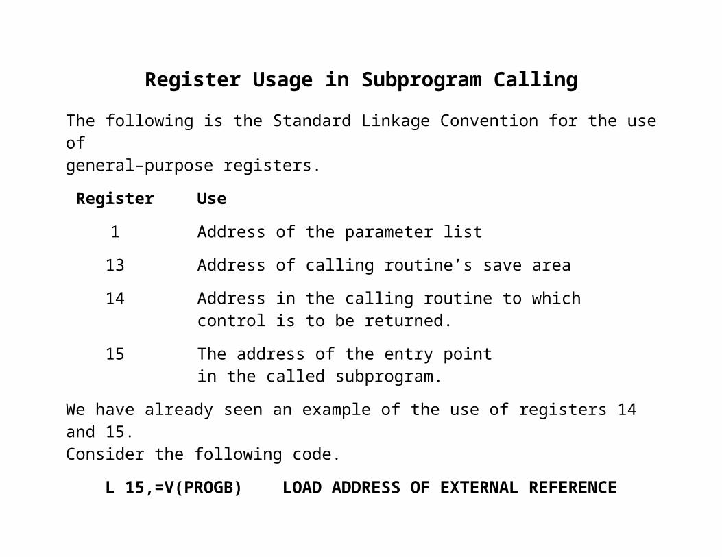
Register Usage in Subprogram Calling
The following is the Standard Linkage Convention for the use of general–purpose registers.
Register Use
1 Address of the parameter list
13 Address of calling routine’s save area
14 Address in the calling routine to whichcontrol is to be returned.
15 The address of the entry point in the called subprogram.
We have already seen an example of the use of registers 14 and 15.Consider the following code.
L 15,=V(PROGB) LOAD ADDRESS OF EXTERNAL REFERENCE BALR 14,15 STORE RETURN ADDRESS INTO R14

The SAVE Macro
Often the first executable instruction of a program will be SAVE (14,12). Here isthe actual code from the second lab assignment, in which I chose to expand macros.
31 LAB02 CSECT 32 SAVE (14,12) SAVE CALLER’S REGISTERS34+ DS 0H 35+ STM 14,12,12(13) 36 BALR R12,0 ESTABLISH ADDRESSABILITY37 USING *,R12 38 LA R2,SAVEAREA LINK THE SAVE AREAS39 ST R2,8(,R13) 40 ST R13,SAVEAREA+4 41 LR R13,R2 On entry, general–purpose register 13 contains the address of the supervisor’s save area. The SAVE macro is written under this assumption.
The program executes as a subprogram of the supervisor (Operating System).
Recall that the address designated 12(13) corresponds to an offset of 12 from the value stored in register 13.
If R13 contains address S0, then 12(13) corresponds to address (S0 + 12).

The User Program Saves the Registers
In this illustration, assume the following.
1. The save area of the supervisor begins at address S0.
2. The user main program is PA, with save area starting at address SA.
3. The user program calls program PB, which has save area starting at SB.
This is the case on entry to main program PA. Register 13 points to the start of the save area for the supervisor and 12(13) points to the start of its register save area.
The instruction STM 14,12,12(13) is then executed. The contents of the supervisor’s save area is now as follows.

The User Program Links the Save Areas
The next step is to establish addressability in the user program, so that addressessuch as that of the save area can be used. The user program then forward links the supervisor’s save area. Before that happens, we just have two save areas.
Here is the code to do the forward link. The address of the start of the user save area is placed in the fullword at offset 8 from the start of the supervisor’s save area.
38 LA R2,SA LINK THE SAVE AREAS39 ST R2,8(,R13) OFFSET 8 FROM S0

The User Program Links the Save Areas (Part 2)
The program now executes the following code to establish the backward link from the user program to the supervisor’s save area.
40 ST R13,SA+4 At this point, register R13 contains the address of the supervisor’s save area.The result of this instruction is the completion of the two–way links.
Now R2 holds the address of the user save area. Note that this could have been any of the registers in the range 2 – 12, excepting 12 which was used for addressability.
The next instruction established R13 as once again holding the address of the save area of the current program.
41 LR R13,R2

The Chain Continues
Suppose the user program calls a subprogram. The chain is continued.

The Return Process
The return process restores the general–purpose registers to their values before the call of the subroutine.
R13 is first restored to point to the save area for the calling program.Then the other general–purpose registers are restored.
Here is the situation on return from Subprogram PB.
The code is as follows. L R13,SB+4 GET ADDRESS OF CALLER’S SAVE AREA LM R14,R12,12(R13) RELOAD THE REGISTERS. R14 IS LOADED WITH THE RETURN ADDRESS BR R14 RETURN TO THE CALLER

Entry/Exit Considerations
Consider how a program or subprogram starts and exits.
The start code is something like the following.
SUB02 CSECT SAVE (14,12) SAVE CALLER’S REGISTERS+ DS 0H + STM 14,12,12(13) BALR R12,0 LOAD R12 WITH THE ADDRESS USING *,R12 OF THE NEXT INSTRUCTION
Here is the standard exit code. Assume the save area is at address SB. L R13,SB+4 ADDRESS OF CALLERS SA LM R14,R12,12(R13) CALLER’S REGISTER VALUES BR R14 RETURNNote that the next to last instruction in the second section causes addressability in the called program to be lost. This is due to the fact that the value that had been loaded into R12 to serve as the base register for this code’s addressability has been overwritten.
Setting the Return Code
The IBM linkage standard calls for general–purpose register R15 to be loaded with a return code indicating success or failure. A value of 0 usually denotes a success.
It is common to set the return code just before the terminating BR instruction, just after the restoration of the calling routine’s registers.
The following is typical code. Here, I am setting a return code of 3.
L R13,SB+4 ADDRESS OF CALLERS SA LM R14,R12,12(R13) CALLER’S REGISTER VALUES LA R15,3 LOAD CODE INTO R15 BR R14 RETURNThis uses the LA (Load Address) instruction in its common sense as a way to load a non–negative constant less than 4,096 into a general–purpose register.
Note that an instruction such as L R15,=H‘3’ would require access to an element in the subprogram’s literal pool. However, the value of the subprogram’s base register has been overwritten, and addressability has been lost.
Another way to set the return code to 0 would be to execute the instruction SR R15,R15.
The Dummy Section (DSECT)
Recall that parameters are passed by reference when it is desired to allow the called program to change the values as stored in the calling program.
Call by reference involves passing an address for a parameter. This address is then used as a target for a new value to be passed back to the calling program.
For passing large quantities of data, it is convenient to use a dummy section.This process is best considered as passing a record structure to the called subprogram.
1. All the data items to be passed to the called program are grouped in a contiguous data block.
2. The address of this data block is passed to the called subprogram.
3. The called subprogram accesses items in the data block by offset from the address passed to it.
The DSECT is used in the called subprogram as a template for the assembler to generate the proper address offsets to be used in accessing the original data.
Example of Linkage Using a DSECT
Suppose that I want to pass customer data from PROGA (the calling program, in which the data are defined) to subprogram PROGB, in which they are used.
Here is a sketch of code and declarations in the calling program, which is PROGA.This uses the calling convention that R1 holds the address of the parameters.
PROGA CSECT* SECTION TO CALL PROGB LA R1,=A(CREC) LOAD RECORD ADDRESS L R15,=V(PROGB) LOAD ADDRESS OF PROGB BALR R14,R15 CALL THE SUBPROGRAM Next Instruction
CREC DS 0CL96 THE RECORD WITH ITS SUBFIELDSCNAME DS CL30 OFFSET = 0CADDR1 DS CL20 OFFSET = 30CADDR2 DS CL20 OFFSET = 50CCITY DS CL15 OFFSET = 70CSTATE DS CL2 OFFSET = 85CZIP DS CL9 OFFSET = 87
The Dummy Section Itself
The dummy section will be declared in the called subprogram using a DSECT.
Here is the proper declaration for our case.
CRECB DSECTCNAME DS CL30 OFFSET = 0CADDR1 DS CL20 OFFSET = 30CADDR2 DS CL20 OFFSET = 50CCITY DS CL15 OFFSET = 70CSTATE DS CL2 OFFSET = 85CZIP DS CL9 OFFSET = 87The DSECT is a convenient means that can be used to describe the layout of a storage area without actually reserving storage.
In use of a DSECT, it is assumed that the storage has been reserved elsewhere and that the base address of that storage will be passed as a parameter.
The DSECT is just a mechanism to instruct the assembler on generation of offsets from the base address into this shared data area.

Use of the DSECT in PROGB
Here is a sketch of the use of the DSECT in PROGB, assembled independently.Recall that general–purpose register R1 contains the address of the customer record.
PROGB CSECT BALR R12,0 ESTABLISH ADDRESSABILITY USING *,R12 LR R10,R1 GET THE PARAMETER ADDRESS USING CRECB,R10 ESTABLISH ADDRESSABILITY FOR THE DUMMY SECTION MVC OUTC,CCITY THIS ACCESSES THE DATA IN THE CALLING PROGRAM
CCITY DS CL15 DATA BELONGING TO PROGBCRECB DSECTCNAME DS CL30 OFFSET = 0CADDR1 DS CL20 OFFSET = 30CADDR2 DS CL20 OFFSET = 50CCITY DS CL15 OFFSET = 70CSTATE DS CL2 OFFSET = 85CZIP DS CL9 OFFSET = 87

A Detailed Look at Addresses
Here we recall two facts relative to the one instruction MVC OUTC,CCITY.
The label OUTC belongs to the called subprogram PROGB. It is accessed using base register R12, which is the basis for addressability in this subprogram.
The label CCITY belongs to the dummy section. It is accessed using the base register explicitly associated with the DSECT; here it is R10.
Suppose that OUTC has address X‘100’ (decimal 256) within PROGB, it is at that displacement from the value contained in the base register R12.
From the DSECT it is clear that the label CCITY is at displacement 70 (X‘46’) from the beginning of the data record. The field has length 15, or X‘0F’
The instruction MVC OUTC,CCITYcould have been written as MVC 256(15,R12),70(R10).The object code is thus D2 0E C1 00 A0 46D2 is the operation code for MVC. 0E encodes decimal 14, one less than the length.
C1 00 represents an address at displacement X‘100’ from base register 12.A0 46 represents an address at displacement X‘46’ from base register 10.