subscale lifecycle test of thermal arcjet thruster...
TRANSCRIPT
Subscale Lifecycle Test of Thermal Arcjet ThrusterTALOS for the Lunar Mission BW1
IEPC-2007-137
Presented at the 30th International Electric Propulsion Conference, Florence, ItalySeptember 17-20, 2007
D. Bock∗ , G. Herdrich†and H.-P. Röser.‡
Institut für Raumfahrtsysteme, Pfaffenwaldring 31, 70569 Stuttgart, Germany
and
M. Auweter-Kurtz§
Universität Hamburg, Hamburg, Germany
The performance of the thermal arcjet thruster Talos for the lunar mission Bw1 hasbeen investigated during 30 hours of operation. The operation cycles of this investigationwere one hour on / one hour off cycles as planned during operation on-board the satellite.The aim of this investigation is the determination of performance changes due to nozzlethroat closure or expansion as well as ignition reliability and thruster operation during theignition phase. During the test campaign, the thruster is operated in current regulatedmode with an initial electrical power of 700 W. The mass flow rate for ignition is set to28 mg/s, for the phase from ignition to stable operation to 35 mg/s and for stable operationto 25 mg/s. This results in an average of 26 mg/s during the one hour operation for allconducted tests. This is well within the mission requirement of a mass flow rate between20 and 30 mg/s. The so-called burn-in period of the thruster, where the voltage of thethruster and thus the electrical power continuously increases, is identified to end after 15hours of operation. Optical inspection and determination of the nozzle throat diameteris conducted prior to thruster operation and after 1, 5, 10, 20 and 30 hours of operation.The result of this investigation shows an overall increase in nozzle throat diameter from0.6 mm prior to experiment to 0.66 mm after 30 hours of operation. However, it is found thatthis increase in the nozzle throat diameter has no major effect on thruster performance.During thruster operation, fluctuations of voltage and therefore feed line pressure occurredup to a maximum of seven times during one test. This fluctuations have been found tobe non-critical for thruster operation, but further investigations on this phenomenon aregoing to be conducted. Although the ignition reliability is very high, sparks occurred atignition occasionally. This is identified to be one of the major reasons for anode erosion. Itis supposed that a change of propellant injection into the discharge chamber may minimizethese effects.
∗Research Engineer, Space Transportation Technology, [email protected].†Section Head, Space Transportation Technology.‡Professor, Head of Institute.§President, Universität Hamburg.
1The 30th International Electric Propulsion Conference, Florence, Italy
September 17-20, 2007
Nomenclature
ce = effective exhaust velocityd = nozzle throat diameterp = feed line pressurem = mass flowA = areaF = thrustI = currentIs = specific impulseMe = effective molecular weightU = voltageP = electric powerT0 = combustion chamber temperatureηF = thrust efficiency
I. Introduction
The Lunar Mission Bw1 is one of the four small satellite missions within the small satellite program ofthe Institut für Raumfahrtsysteme (Irs), Universität Stuttgart.1 For this all-electrical satellite mission twodifferent electric propulsion systems are used. One propulsion system consists of a cluster of instationarypulsed plasma thrusters, Simp-Lex,2 and the other propulsion system is a thermal arcjet thruster system.It consists of the thruster – Talos –, the propellant feed system, and the power supply and control unit forthruster and feed system.3 The propellant of the thermal arcjet thruster is gaseous ammonia.
The flight to the moon is divided into four distinct phases: Phase one starts after separation from thelauncher in GTO and lasts until the spacecraft perigee is raised above the outer van-Allen-belt. The secondmission phase stretches from there to the Moon’s sphere of influence, whereas phase three extends to thestable elliptical lunar capture orbit at an altitude of about 1400 km above the lunar surface. During the finalmission phase the satellite is inserted into a circular polar mission orbit at an altitude of 100 km around theMoon. For mission phases one and four, the thermal arcjet thruster is used. Development and qualificationof the two thruster systems is completely accomplished at Irs in cooperation with industrial partners. Thepresent paper will focus on the thermal arcjet thruster system.After first optimization investigations of the thermal arcjet thruster had been conducted with respect to therequirements of the lunar mission Bw1 (thrust 100 mN, maximum electrical input power for thruster system1 kW, mass flow rate between 20 and 30 mg/s and assumed lifetime of 700 hours) and after one possibleoperating point had been defined in earlier work, investigations of the thruster performance for operatingcycles as foreseen at the lunar mission Bw1 – 1 hour on / 1 hour off – are being conducted at the moment.
During this multi-hour test campaign the thermal arcjet thruster is disassembled and optical investiga-tion and measurement of the nozzle throat diameter is done after 1 hour, 5 hours, 10 hours, 20 hours and30 hours of operation. Thus, possible changes in the constrictor area are monitored. They could be causedon one hand by the thermal load at the nozzle throat during an experiment, which can come close to themelting temperature of the material. On the other hand the ignition procedure is found to be one of thecritical points concerning anode erosion. Furthermore, the temperature cycles may cause material problemsconcerning material viscosity.Considering the work of Kinefuchi et. al., a 30 hour test period is chosen as the constrictor closure phe-nomenon and crack generation are observed mainly in the first 30 hours of operation for thermal arcjets inthe low power class.4 As during previous projects constrictor closure phenomenon appeared and was one ofthe lifetime limiting factors, special focus is laid on the investigation of anode erosion effects in this study.5,6
The cathode gap is adjusted to 0.8 mm prior to the first experiment and is not corrected during the 30hour test period. This is done to get a realistic impact of cathode erosion effects on thruster performance incomparison to the operation on board the satellite, where no cathode adjustment is foreseen.The operating point investigated in the presented study is 25 mg/s ammonia mass flow rate during stationaryoperation with 10 A current at an initial electric input power of 700 W. The experiments are conducted in
2The 30th International Electric Propulsion Conference, Florence, Italy
September 17-20, 2007
a current controlled mode, so that during the test period the electric input power increases due to changesin the voltage of the arc. During all experiments, the current, voltage, electric power, thrust and feed linepressure as well as the mass flow and the outer nozzle surface temperature are monitored.
This paper discusses the results obtained during the first hours of operation with a new thruster nozzlemade of tungsten doped with two percent thorium-oxide concerning the correlation between the nozzlethroat diameter change and changes in thruster performance. As a result of the first 30 hours of operationa prediction concerning the overall expected lifetime of the thruster is obtained.
II. Apparatus and Experimental Setup
The lifetime requirement for the thermal arcjet thruster coming from the lunar mission Bw1 is expectedto be 700 hours of operation in total. Due to the limited energy available on-board the satellite and thenecessity to recharge the batteries, the thruster will be operated in cycles of one hour on / one hour off duringthe thruster phase of operation. To simulate these operation cycles within the test campaign described inthis paper one hour on / one hour off cycles are conducted with longer breaks after a few cycles, because noautomation of the test is done so far. Furthermore, for inspection of the nozzle the vacuum chamber has tobe opened and the thruster has to be disassembled. The concept behind this test campaign is to get an ideaof the thruster behavior at a constant working point during a longer time of operation.During former tests and in literature it has been found that each thruster has a so-called burn in period.4The time of this period for the investigated thruster is defined by this test campaign. As the main impacton anode erosion is found to be the ignition phase of the thruster,4–6 numerous restarts of the thruster areimportant in order to investigate anode erosion effects.
A. Thermal Arcjet Thruster
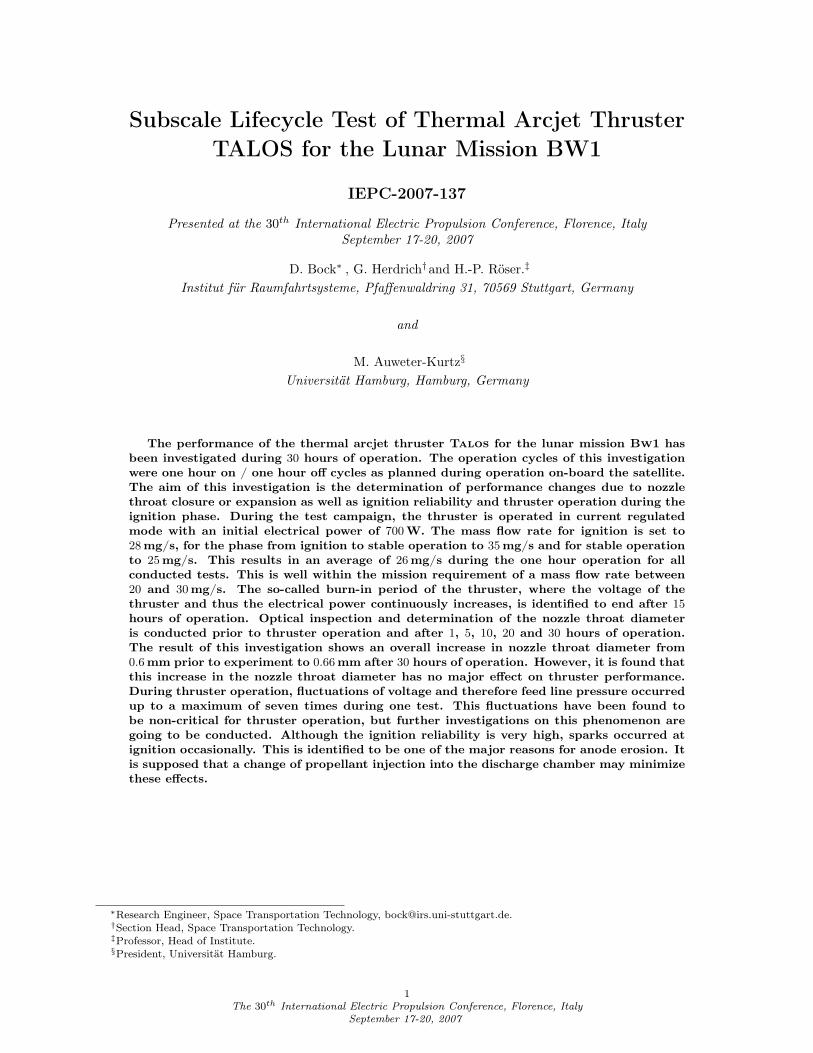
The thruster, a radiation cooled type, is developed on basis of an engineering model in the 1 to 1.5 kW classfor use with hydrazine as propellant.7 A diagram of the thruster is shown in fig. 1.
nozzle
gas supply
insulator
cathode
housinginjector / insulator
compressionspring
Figure 1. Diagram of thruster
The modular design of the laboratory model allows to remove
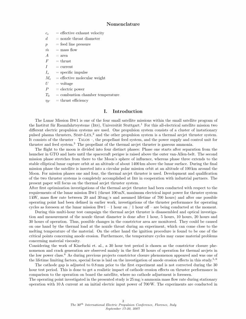
Figure 2. Geometry of nozzle
the anode and all other internal parts after disconnecting rear andfront part of the housing. Doing so, the inspection of the nozzle caneasily be conducted.The nozzle, which is the annular anode of the thruster, is a tungsten-alloy doped with two percent of thorium-oxide. The nozzle geometryis shown in fig. 2. The nozzle throat diameter is 0.6 mm, the lengthis 0.7 mm and the area ratio – nozzle exit area to nozzle throat area– is 279. The central cathode has a diameter of 3 mm and is made ofthe same material as the anode. Sealing between the anode and thehousing is accomplished by use of a graphite gasket. The necessarysealing force is applied by a compression spring in the rear part of the thruster. The propellant is injectedinto the gap between the two electrodes. The heating process of the propellant takes place inside the electricarc between cathode and anode. The propellant is accelerated and expanded inside the nozzle and thus theheating energy is transfered into directed kinetic energy. The plasma plume characteristic of thermal arcjetthrusters shows a hot and energy rich core with high velocity and high temperature and a relatively cold gas
3The 30th International Electric Propulsion Conference, Florence, Italy
September 17-20, 2007
layer at its edge. The cold gas layer, which is also present in the nozzle throat, has the important effect ofcooling the nozzle material during operation and thus limiting anode erosion effects.
B. Test Facility
The facility used for the test campaign is a stainless steel vacuum chamber of 1.2 m in diameter and 2 m inlength. The 3-stage pumping system of this test facility is capable of providing a background pressure of5 × 10−2 hPa during thruster operation at a mass flow rate of 25 mg/s ammonia. A pendulum type thruststand with a non-contact displacement sensor is integrated into the vacuum chamber. In-situ calibrationof the thrust stand is conducted prior to every experiment. All thrust measurement data is corrected forthermal related zero shift.During each test, current, voltage, mass flow rate, thrust, feed line pressure and nozzle surface temperatureare monitored. Current and mass flow rate are regulated. The operating point is defined at 10 A current anda mass flow rate of 25 mg/s ammonia. The propellant delivery system consists of an ammonia gas cylinder,where the ammonia is stored under 6 × 10³ hPa, a thermal mass flow regulator and stainless steel pipingsystem. The thermal mass flow regulator has been calibrated prior to the test campaign by use of a so-called’Sartorius’ balance with an accuracy of 10 mg. Pressure measurement of the propellant is done by use of apressure transducer inside the vacuum chamber. The power supply of the thruster provides a breakdownvoltage of about 2000 V, up to 140 V during operation of the arcjet and a direct current of up to 25 A.
III. Thruster Performance
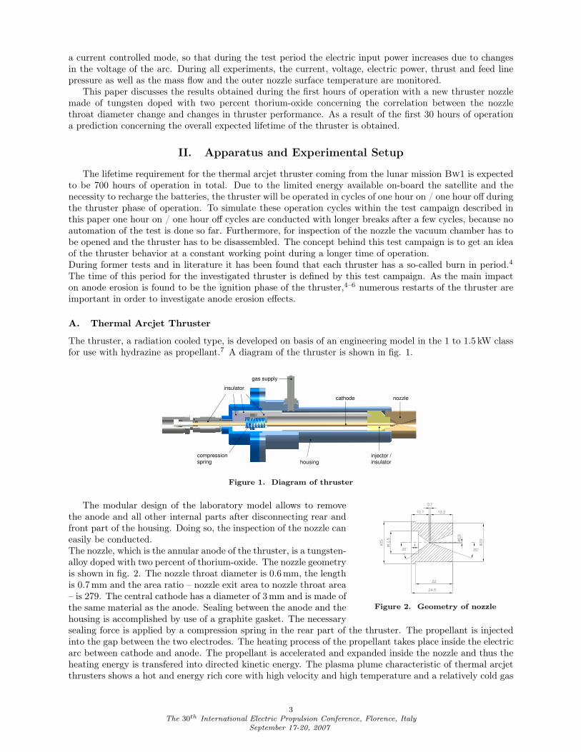
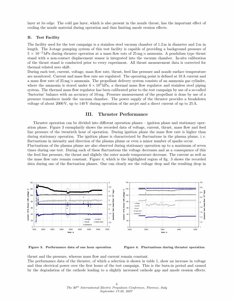
Thruster operation can be divided into different operation phases – ignition phase and stationary oper-ation phase. Figure 3 exemplarily shows the recorded data of voltage, current, thrust, mass flow and feedline pressure of the twentieth hour of operation. During ignition phase the mass flow rate is higher thanduring stationary operation. The ignition phase is characterized by fluctuations in the plasma plume, i. e.fluctuations in intensity and direction of the plasma plume or even a minor number of sparks occur.Fluctuations of the plasma plume are also observed during stationary operation up to a maximum of seventimes during one test. During each of these fluctuations the voltage decreases and as a consequence of thisthe feed line pressure, the thrust and slightly the outer nozzle temperature decrease. The current as well asthe mass flow rate remain constant. Figure 4, which is the highlighted region of fig. 3 shows the recordeddata during one of the fluctuation phases. One can clearly see the voltage drop and the resulting drop in
0
20
40
60
80
100
120
140
1500 2000 2500 3000 3500 4000 4500 5000 5500
time / s
cu
rren
t /
10*A
; th
rust
/ m
N;
vo
ltag
e /
V
0
0.5
1
1.5
2
2.5
3
3.5
4
4.5
5
pre
ssu
re /
bar;
mass f
low
/ 1
0-1
mg
/s
voltage current
thrust mass flow
pressure
Figure 3. Performance data of one hour operation
0
20
40
60
80
100
120
140
3250 3300 3350 3400 3450
time / s
cu
rren
t /
10*A
; th
rust
/ m
N;
vo
ltag
e /
V
1
1.2
1.4
1.6
1.8
2
2.2
2.4
2.6
2.8
pre
ssu
re /
bar;
mass f
low
/ 1
0-1
mg
/svoltage
current
thrust
mass flow
pressure
Figure 4. Fluctuations during thruster operation
thrust and the pressure, whereas mass flow and current remain constant.The performance data of the thruster, of which a selection is shown in table 1, show an increase in voltageand thus electrical power over the first hours of the test campaign. This is the burn-in period and causedby the degradation of the cathode leading to a slightly increased cathode gap and anode erosion effects.
4The 30th International Electric Propulsion Conference, Florence, Italy
September 17-20, 2007
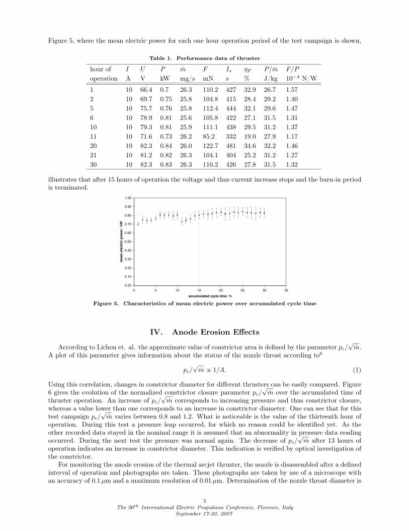
Figure 5, where the mean electric power for each one hour operation period of the test campaign is shown,
Table 1. Performance data of thruster
hour of I U P m F Is ηF P/m F/P
operation A V kW mg/s mN s % J/kg 10−4 N/W
1 10 66.4 0.7 26.3 110.2 427 32.9 26.7 1.572 10 69.7 0.75 25.8 104.8 415 28.4 29.2 1.405 10 75.7 0.76 25.8 112.4 444 32.1 29.6 1.476 10 78.9 0.81 25.6 105.8 422 27.1 31.5 1.3110 10 79.3 0.81 25.9 111.1 438 29.5 31.2 1.3711 10 71.6 0.73 26.2 85.2 332 19.0 27.9 1.1720 10 82.3 0.84 26.0 122.7 481 34.6 32.2 1.4621 10 81.2 0.82 26.3 104.1 404 25.2 31.2 1.2730 10 82.3 0.83 26.3 110.2 426 27.8 31.5 1.32
illustrates that after 15 hours of operation the voltage and thus current increase stops and the burn-in periodis terminated.
0.00
0.10
0.20
0.30
0.40
0.50
0.60
0.70
0.80
0.90
1.00
0 5 10 15 20 25 30 35
accumulated cycle time / h
mean
ele
ctr
ic p
ow
er
/ kW
Figure 5. Characteristics of mean electric power over accumulated cycle time
IV. Anode Erosion Effects
According to Lichon et. al. the approximate value of constrictor area is defined by the parameter pc/√
m.A plot of this parameter gives information about the status of the nozzle throat according to6
pc/√
m ∝ 1/A. (1)
Using this correlation, changes in constrictor diameter for different thrusters can be easily compared. Figure6 gives the evolution of the normalized constrictor closure parameter pc/
√m over the accumulated time of
thruster operation. An increase of pc/√
m corresponds to increasing pressure and thus constrictor closure,whereas a value lower than one corresponds to an increase in constrictor diameter. One can see that for thistest campaign pc/
√m varies between 0.8 and 1.2. What is noticeable is the value of the thirteenth hour of
operation. During this test a pressure leap occurred, for which no reason could be identified yet. As theother recorded data stayed in the nominal range it is assumed that an abnormality in pressure data readingoccurred. During the next test the pressure was normal again. The decrease of pc/
√m after 13 hours of
operation indicates an increase in constrictor diameter. This indication is verified by optical investigation ofthe constrictor.
For monitoring the anode erosion of the thermal arcjet thruster, the nozzle is disassembled after a definedinterval of operation and photographs are taken. These photographs are taken by use of a microscope withan accuracy of 0.1 µm and a maximum resolution of 0.01 µm. Determination of the nozzle throat diameter is
5The 30th International Electric Propulsion Conference, Florence, Italy
September 17-20, 2007
0.8
1
1.2
1.4
1.6
1.8
2
0 5 10 15 20 25 30 35
accumulated cycle time / h
no
rmali
zed
pre
ssu
re/s
qrt
(massfl
ow
) /
-
Figure 6. Anode characteristics
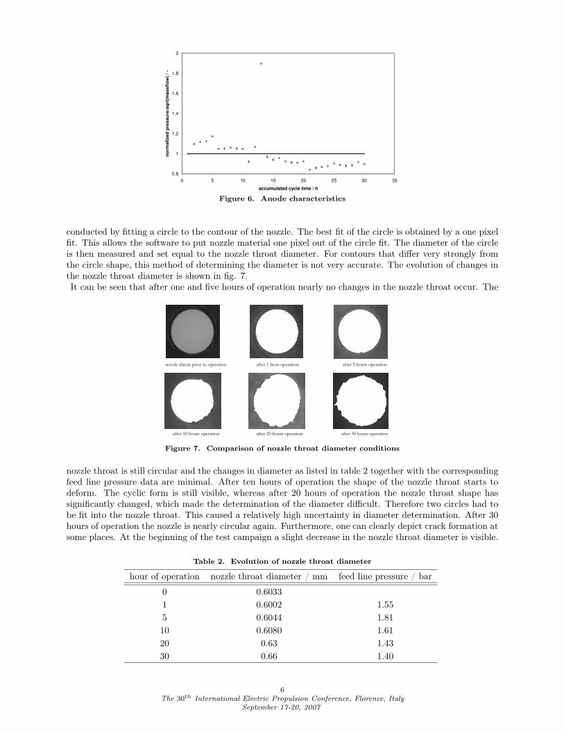
conducted by fitting a circle to the contour of the nozzle. The best fit of the circle is obtained by a one pixelfit. This allows the software to put nozzle material one pixel out of the circle fit. The diameter of the circleis then measured and set equal to the nozzle throat diameter. For contours that differ very strongly fromthe circle shape, this method of determining the diameter is not very accurate. The evolution of changes inthe nozzle throat diameter is shown in fig. 7.It can be seen that after one and five hours of operation nearly no changes in the nozzle throat occur. The
nozzle throat prior to operation after 1 hour operation after 5 hours operation
after 10 hours operation after 20 hours operation after 30 hours operation
Figure 7. Comparison of nozzle throat diameter conditions
nozzle throat is still circular and the changes in diameter as listed in table 2 together with the correspondingfeed line pressure data are minimal. After ten hours of operation the shape of the nozzle throat starts todeform. The cyclic form is still visible, whereas after 20 hours of operation the nozzle throat shape hassignificantly changed, which made the determination of the diameter difficult. Therefore two circles had tobe fit into the nozzle throat. This caused a relatively high uncertainty in diameter determination. After 30hours of operation the nozzle is nearly circular again. Furthermore, one can clearly depict crack formation atsome places. At the beginning of the test campaign a slight decrease in the nozzle throat diameter is visible.
Table 2. Evolution of nozzle throat diameter
hour of operation nozzle throat diameter / mm feed line pressure / bar
0 0.60331 0.6002 1.555 0.6044 1.8110 0.6080 1.6120 0.63 1.4330 0.66 1.40
6The 30th International Electric Propulsion Conference, Florence, Italy
September 17-20, 2007
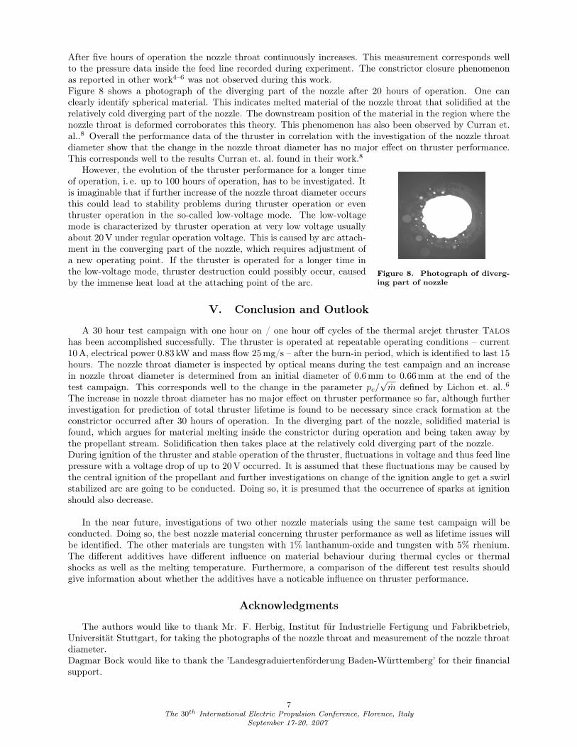
After five hours of operation the nozzle throat continuously increases. This measurement corresponds wellto the pressure data inside the feed line recorded during experiment. The constrictor closure phenomenonas reported in other work4–6 was not observed during this work.Figure 8 shows a photograph of the diverging part of the nozzle after 20 hours of operation. One canclearly identify spherical material. This indicates melted material of the nozzle throat that solidified at therelatively cold diverging part of the nozzle. The downstream position of the material in the region where thenozzle throat is deformed corroborates this theory. This phenomenon has also been observed by Curran et.al..8 Overall the performance data of the thruster in correlation with the investigation of the nozzle throatdiameter show that the change in the nozzle throat diameter has no major effect on thruster performance.This corresponds well to the results Curran et. al. found in their work.8
However, the evolution of the thruster performance for a longer time
Figure 8. Photograph of diverg-ing part of nozzle
of operation, i. e. up to 100 hours of operation, has to be investigated. Itis imaginable that if further increase of the nozzle throat diameter occursthis could lead to stability problems during thruster operation or eventhruster operation in the so-called low-voltage mode. The low-voltagemode is characterized by thruster operation at very low voltage usuallyabout 20 V under regular operation voltage. This is caused by arc attach-ment in the converging part of the nozzle, which requires adjustment ofa new operating point. If the thruster is operated for a longer time inthe low-voltage mode, thruster destruction could possibly occur, causedby the immense heat load at the attaching point of the arc.
V. Conclusion and Outlook
A 30 hour test campaign with one hour on / one hour off cycles of the thermal arcjet thruster Taloshas been accomplished successfully. The thruster is operated at repeatable operating conditions – current10 A, electrical power 0.83 kW and mass flow 25 mg/s – after the burn-in period, which is identified to last 15hours. The nozzle throat diameter is inspected by optical means during the test campaign and an increasein nozzle throat diameter is determined from an initial diameter of 0.6 mm to 0.66 mm at the end of thetest campaign. This corresponds well to the change in the parameter pc/
√m defined by Lichon et. al..6
The increase in nozzle throat diameter has no major effect on thruster performance so far, although furtherinvestigation for prediction of total thruster lifetime is found to be necessary since crack formation at theconstrictor occurred after 30 hours of operation. In the diverging part of the nozzle, solidified material isfound, which argues for material melting inside the constrictor during operation and being taken away bythe propellant stream. Solidification then takes place at the relatively cold diverging part of the nozzle.During ignition of the thruster and stable operation of the thruster, fluctuations in voltage and thus feed linepressure with a voltage drop of up to 20 V occurred. It is assumed that these fluctuations may be caused bythe central ignition of the propellant and further investigations on change of the ignition angle to get a swirlstabilized arc are going to be conducted. Doing so, it is presumed that the occurrence of sparks at ignitionshould also decrease.
In the near future, investigations of two other nozzle materials using the same test campaign will beconducted. Doing so, the best nozzle material concerning thruster performance as well as lifetime issues willbe identified. The other materials are tungsten with 1% lanthanum-oxide and tungsten with 5% rhenium.The different additives have different influence on material behaviour during thermal cycles or thermalshocks as well as the melting temperature. Furthermore, a comparison of the different test results shouldgive information about whether the additives have a noticable influence on thruster performance.
Acknowledgments
The authors would like to thank Mr. F. Herbig, Institut für Industrielle Fertigung und Fabrikbetrieb,Universität Stuttgart, for taking the photographs of the nozzle throat and measurement of the nozzle throatdiameter.Dagmar Bock would like to thank the ’Landesgraduiertenförderung Baden-Württemberg’ for their financialsupport.
7The 30th International Electric Propulsion Conference, Florence, Italy
September 17-20, 2007

References1Laufer, R., Auweter-Kurtz, M., Lengowski, M., Nawaz, A., Röser, H.-P., Schönermark, M., and Wagner, H., “An All
Electrical Small Satellite for a Technology Demonstration and Science Mission to the Moon,” IAC-04-IAF-Q.2.b.05, 55thInternational Astronautical Conference, 2004.
2Nawaz, A., Auweter-Kurtz, M., Herdrich, G., and Kurtz, H., “Impulse measurement and Thermal Investigation of Simp-Lex,” AIAA-2006-4855, 42nd Joint Propulsion Conference, 2006.
3Bock, D., Auweter-Kurtz, M., Kurtz, H., and Röser, H.-P., “Experimental Investigations on Thermal Arcjet ThrusterDevelopment for a Science Mission to the Moon,” IAC-06-C4.4.03, 57th International Astronautical Conference, 2006.
4Kinefuchi, K., Funaki, I., and Toki, K., “Multi-hour Test of Tungsten Anodes for Low Power DC Arcjet,” IEPC-01-192,27th International Electric Propulsion Conference, 2001.
5Zube, D., Messerschmid, E., and Dittmann, A., “Project ATOS – Ammonia Arcjet Lifetime Qualification and SystemComponents Test,” AIAA-1995-2508, 31st Joint Propulsion Conference, 1995.
6Lichon, P. G. and Sankovic, J. M., “Development and Demonstration of a 600-Second Mission-Average Isp Arcjet,” Journalof Propulsion and Power , Vol. 12, No. 6, 1996, pp. 1018–1025.
7Viertel, Y. E., Schmitz, H.-D., Riehle, M., Kurtz, H. L., and Auweter-Kurtz, M., “Development and Test of a 1 kWHydrazine Arcjet System,” AIAA-1996-2960, 32nd Joint Propulsion Conference, 1996.
8Curran, F. M. and Haag, T. W., “An Extended Life and Performance Test of a Low-Power Arcjet,” AIAA-88-3106, 24thJoint Propulsion Conference, 1988.
8The 30th International Electric Propulsion Conference, Florence, Italy
September 17-20, 2007