subsea bop stack shear/seal capability modeling...
TRANSCRIPT
Subsea BOP Stack Shear/Seal Capability Modeling Tool
SwRI® Project No. 18.21614 BSEE Contract No. E15PC00006
OESI Forum February 17, 2017
Steven T. Green
Nicholas J. Mueschke, Ph.D.
Amy B. McCleney, Ph.D.
Joseph H. Bradley
OESI Forum 17 Feb 2017
Agenda
2
Introduction to SwRI
Project Overview
Project Status
Overview of Tasks
Example Results
Simulation Database Tool
OESI Forum 17 Feb 2017
SwRI Introduction
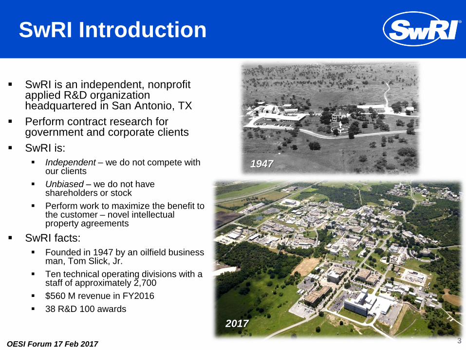
SwRI is an independent, nonprofit applied R&D organization headquartered in San Antonio, TX
Perform contract research for government and corporate clients
SwRI is:
Independent – we do not compete with our clients
Unbiased – we do not have shareholders or stock
Perform work to maximize the benefit to the customer – novel intellectual property agreements
SwRI facts:
Founded in 1947 by an oilfield business man, Tom Slick, Jr.
Ten technical operating divisions with a staff of approximately 2,700
$560 M revenue in FY2016
38 R&D 100 awards
3
1947
2017

OESI Forum 17 Feb 2017
Operational Characteristics
• Applied RDT&E Services
• Revenue from Contracts
• Physical Sciences & Engineering
• Broad Technological Base
• Capital-Intensive Operation
• Internal Research Program
4

OESI Forum 17 Feb 2017
Project Overview - Objectives
Provide guidance to BSEE on simulation
methods that combine mechanical (FEA)
and fluids (CFD) analyses to better
understand the effects of fluid-structure
interactions during BOP blind shear ram
closure.
Develop an extensible software tool that will
allow BSEE to compare anticipated
operating environments and conditions with
a database of previous analysis results
5
This project focused on the
operation of drill pipe shear rams
OESI Forum 17 Feb 2017
Project Overview - Approach
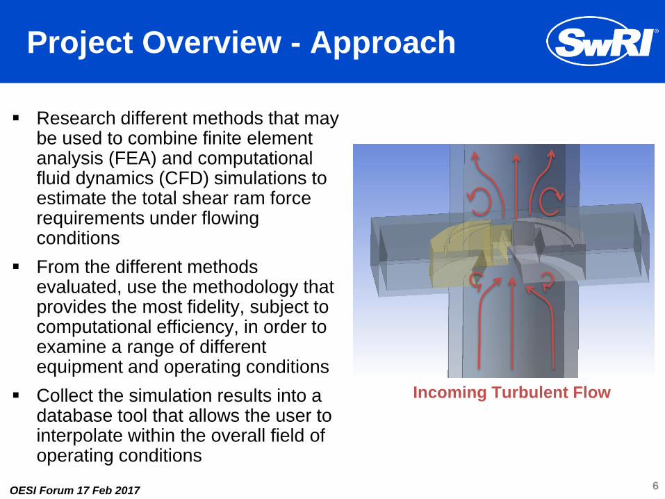
Research different methods that may be used to combine finite element analysis (FEA) and computational fluid dynamics (CFD) simulations to estimate the total shear ram force requirements under flowing conditions
From the different methods evaluated, use the methodology that provides the most fidelity, subject to computational efficiency, in order to examine a range of different equipment and operating conditions
Collect the simulation results into a database tool that allows the user to interpolate within the overall field of operating conditions
6
Incoming Turbulent Flow

OESI Forum 17 Feb 2017
Project Overview
What is the project trying to accomplish?
In the absence of experimental results of shear ram performance under extreme pressures and flowing conditions, what is the optimal simulation methodology for accounting for hydrodynamic effects?
Are there significant parameters that affect the influence of hydrodynamic forces on shear rams?
Can a database of results be compiled to build a software tool that will allow BSEE to compare third-party evaluations of equipment and conditions to new permit applications?
What is it not trying to accomplish?
This is not a manufacturer/equipment comparison study.
It is acknowledged that this is not a full-physics representation of the problem, but rather a study to provide an extra level of physical fidelity that incorporates hydrodynamic effects.
What physical effects are included or not included?
Only single-phase flow of crude oil up the annulus is considered. Multiphase flow of crude or drilling mud is not being simulated. Flow within the drill pipe is not being considered.
Sand, debris, solid matter, and potential erosion effects are not within the scope of this work.
Evaluation of shear ram deformation or failure is not within the scope of this work.
Evaluation of the hydraulic systems or their designs that apply pressure to the shear rams is not within the scope of this work.
Only drill pipe is being considered within the simulations and auxiliary tubing/cables or drill pipe connections are not included.
Off-center pipe and potential bowing/buckling/tension effects are not considered.
Potential operational characteristics, such as flow diversion away from the annulus, are not considered.
7
OESI Forum 17 Feb 2017
Project Tasks - Summary
Task 1: Define Baseline Condition and Parameter Variations
Task 2: Baseline Studies and Modeling Approach Assessment
Task 3: Parametric Simulations
Task 4: Database Tool Development
8
Note that this project is still underway and this presentation
will focus on the project overview, scope, and approach.
Details of the results shall be presented at a later date.
OESI Forum 17 Feb 2017
Task 1: Baseline Case Definition
A baseline set of conditions was selected to perform the
initial analysis of different simulation approaches in Task 2
Conditions specified include:
Wellbore dimensions
Drill pipe specification
Shear ram geometry
Ram closing time
BOP depth
Well depth
Annular flow rate
Fluid properties
Flowing pressure and temperature 9

OESI Forum 17 Feb 2017
Task 2: Modeling Methodologies
In Task 2, different methods for combining mechanical
(FEA) and fluids (CFD) forces are investigated
1-D well flow modeling was used to determine the
conditions at the BOP stack and evaluate potential
transient hydraulic pressure spikes
A tiered approach to evaluating fluid-structure interaction
(FSI) simulation methodologies was investigated:
Tier 1: FEA Only
Tier 2: CFD/FEA Linear Superposition
Tier 3: Lock-Step Coupled CFD/FEA
Tier 4: Dynamically-Coupled CFD/FEA
10

OESI Forum 17 Feb 2017
Tier 2 Simulation - Methodology
1. Use 1-D flow model (OLGA, SINDA/FLUINT) to compute the hydrostatic pressure, temperature, and fluid properties at the BOP. Also, the well modeling was used to assess the annular flow rate through the BOP as a function of area open to flow as the shear rams close.
2. FEA (LS-DYNA) with a Johnson-Cook material model used to simulate the deformation and failure of the drill pipe as the rams are closed. Mechanical shearing forces are computed here.
3. Geometries from the FEA simulation are analyzed at discrete points in time (100%, 40%, 20%, 10%, and 5% of annulus flow area remaining).
4. CFD (Fluent) used to compute the flow field around the ram and the hydrodynamic pressure on the ram faces.
11
Hydrostatic Force
Hydrodynamic Force
Mechanical Shearing Force Total
Ram
Force
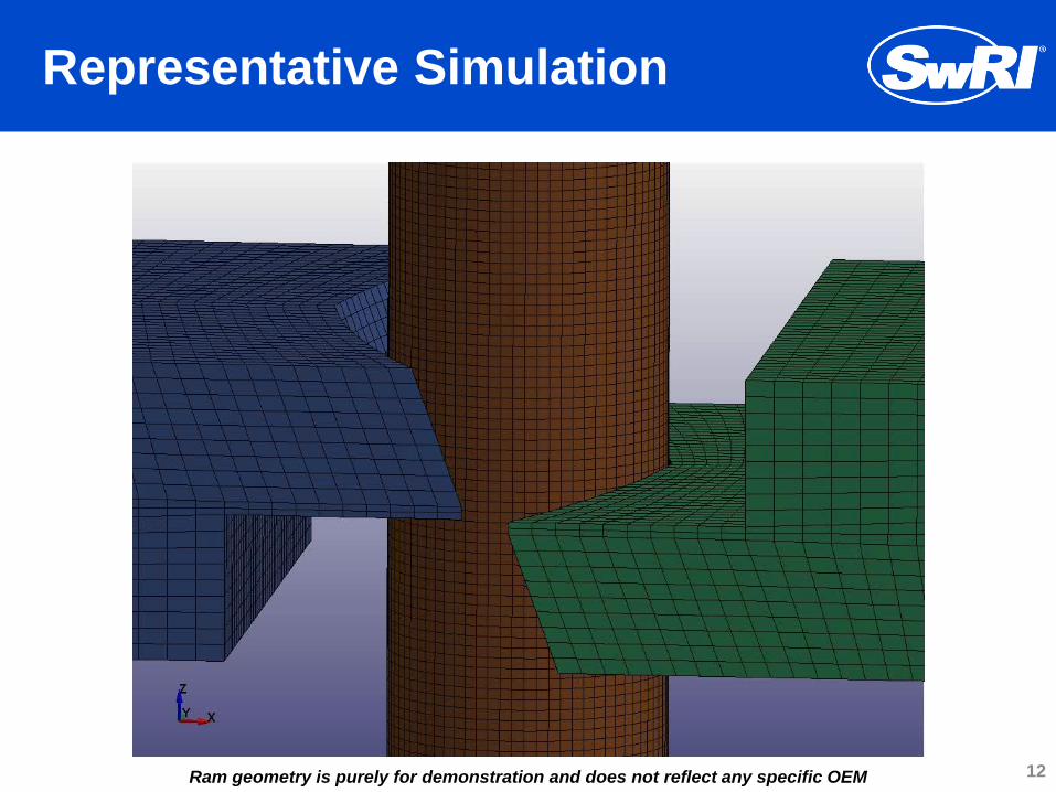
Representative Simulation
12 Ram geometry is purely for demonstration and does not reflect any specific OEM
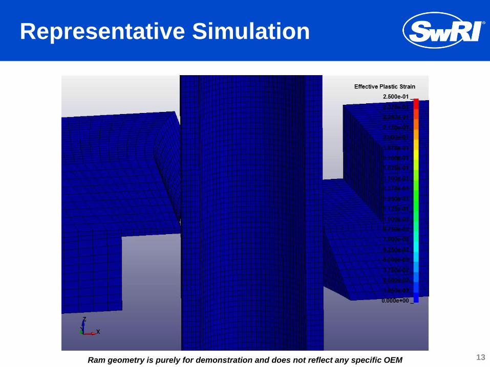
Representative Simulation
13 Ram geometry is purely for demonstration and does not reflect any specific OEM
OESI Forum 17 Feb 2017
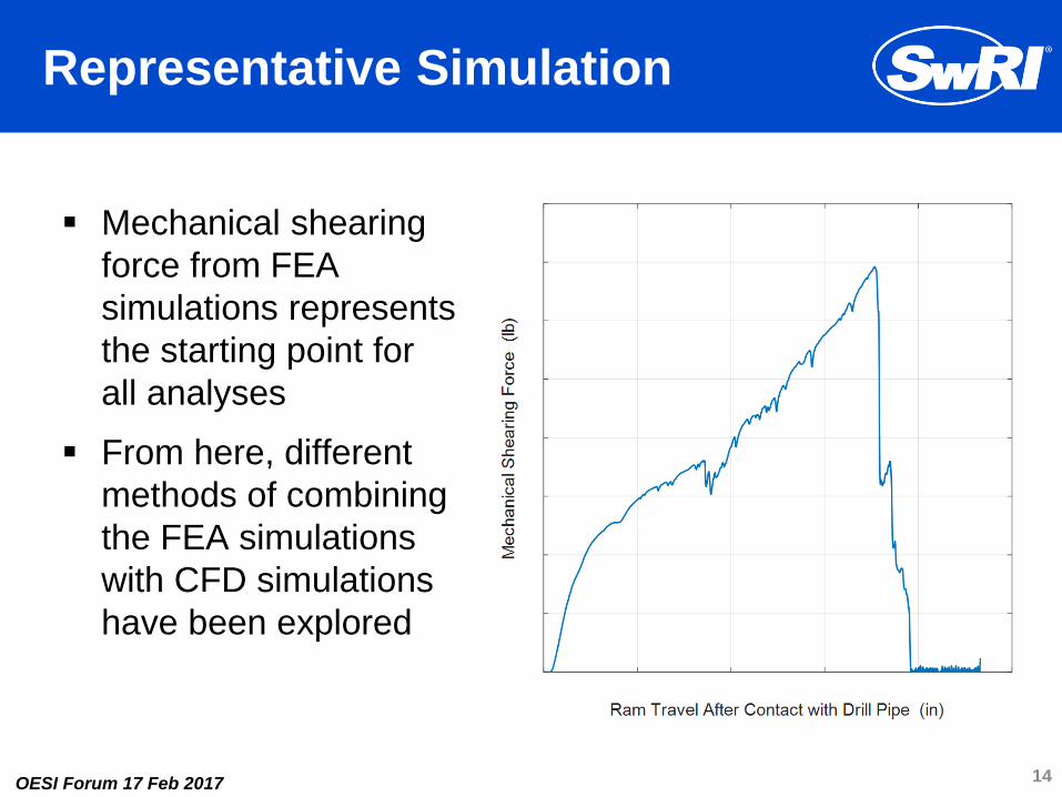
Representative Simulation
Mechanical shearing
force from FEA
simulations represents
the starting point for
all analyses
From here, different
methods of combining
the FEA simulations
with CFD simulations
have been explored
14

Representative Simulation
15
Flow Stream Lines
Local pressure forces
on ram surfaces Schematic of Fluid
Domain of Interest

OESI Forum 17 Feb 2017
Verification and Validation Efforts
Simulated experiments reported in “Final Report 01 – BOP Stack Sequencing and Shear Ram Design,” MCS Kenny, 2013
Good agreement with measured shear forces observed
Shearing of 3-1/2”, 13.3 lb/ft, S-135 drill pipe with 13 5/8” Cameron rams
Note that the simulation model and S-135 drill pipe material model were independently developed and not taken from the 2013 report
Additional shearing simulations of 6 5/8”, 50 lb/ft, S-135 pipe have also been compared with OEM test data (not shown here)
16

OESI Forum 17 Feb 2017
Verification and Validation Efforts
Significant effort was made to verify the proper definition
of the numerical parameters used in the mechanical and
fluids simulations
Numerical and physical parameters examined include:
FEA and CFD grid resolutions
Drill pipe boundary conditions
Computational domain size
Drill pipe material model
Material-on-material contact detection algorithms
Surface-to-surface friction
Turbulence model effects
17

OESI Forum 17 Feb 2017
Comparison of Approximate and OEM Ram Performance
Simulations have been performed using approximated ram geometries and physically accurate ram geometries
Different shearing dynamics may be observed depending upon subtle changes in blade geometry
18
Approximated Ram Geometry Representative Realistic Ram Geometry

OESI Forum 17 Feb 2017
Task 3: Parameter Variation Study
Variations on the baseline case have been simulated to
determine potential affects of hydrodynamic forces under
different conditions
3 different OEM ram geometries
2 different ram closing speeds
2 different annular flow rates
3 different flowing pressures
1 different fluid property
2 different tubing geometries
19

OESI Forum 17 Feb 2017
BOP Ram Force Database Tool
20

OESI Forum 17 Feb 2017
Thank You
Thanks for Your Attention
Any Questions?
21