subsidence study for kolihan copper mine...
TRANSCRIPT

Interim Report
QUARTER -1 Project No.: CONS/2275/2013-14
SUBSIDENCE STUDY FOR KOLIHAN COPPER MINE AT KHETRI COPPER COMPLEX, RAJASTHAN
Sponsored by
HINDUSTAN COPPER LIMITED
Consultant-in-Charge
Dr. Dheeraj Kumar
Team Members Prof. P.P. Bahuguna (Advisor)
Mr. Vasant G. K. Villuri
Md. Soyeb Alam
Prof. D. C. Panigrahi
Technical Support
Shri Sunil Kumar
Department of Mining Engineering Indian School of Mines, Dhanbad
SEPTEMBER 2014
QUARTERLY REPORT PHASE II (Q3)
Project No. CONS/2275/13‐14

Abstract Subsidence impacts occur at every underground mining operation bringing about
changes to surface landforms, ground water and surface water. Although the same
impacts to mining operations, man‐made surface structures and other features are
relatively well known and studied, the environmental impacts related to subsidence at
underground mines are not well known and have not been extensively described. The
Subsidence monitoring work at Kolihan Copper Mine, Khetri Copper Complex, Rajasthan
was awarded to ISM vide the LOI no. HCL/HO/KCC/SS/2013 dated 07.08.2013 and WO
no. HCL/HO/KCC/SS/2013 dated 20.09.13 for a period of 2 years and one month w.e.f.
07.08.2013.
In the 20th Meeting of the Reconstituted Expert Appraisal Committee for Environmental
Appraisal of Mining Projects (Non‐Coal) of the Ministry of Environment and Forests
during May 28‐30, 2014, periodically monitoring of ground movement at Kolihan Copper
mine systematically as carried out by ISM Dhanbad through establishing subsidence
pillars was noted by the committee based on the interim report submitted by ISM. It
was desired to submit the Final report. The final report depicting the result of two
Quarters (Year 1: Q1 & Q2 at an interval of 3 months each) subsidence monitoring as
carried by ISM as per the scope of the subsidence study was submitted to HCL in July
2014
This Report presents the following:
1. Brief description of mine, geology, mining methods, etc.
2. Subsidence monitoring methodology along with impacts of subsidence at
underground hard‐rock metal mine at Kolihan
3. Results of quarterly monitoring of subsidence monitoring stations in 3‐dimensions
(X, Y and Z) as carried out by Mine Surveying Section, Department of Mining
Engineering, ISM Dhanbad during Q3 (August 8 – 18, 2014).

Page3
SUBSIDENCE STUDY FOR KOLIHAN COPPER MINE AT KHETRI COPPER COMPLEX, RAJASTHAN
1. INTRODUCTION
Environmental Clearance w.r.t. Kolihan Copper Mine in Village – Kolihan, Tehsil –Khetri,
District – Jhunjhunu, State – Rajasthan having a lease area of 163.23 Hectares (ML No. 08/95)
was obtained as per letter no. J-11015/378//2007-IA.II (M) dated 04th March’ 2009 from
Government of India, Ministry of Environment & Forest. The management of Kolihan Copper
Mine, Hindustan Copper Ltd. approached Ministry of Environment and Forest (MoEF), Govt. of
India, seeking Prior Environmental Clearance for enhancement of production capacity from 1.00
Million Tonnes / Year to 1.50 Million Tonnes /year. MoEF vide its letter no. J-11015/61/2012-
IA.II (M) dated 23.07.2012 prescribed a TOR for undertaking detailed EIA study for the
purpose of obtaining prior environmental clearance under provision of EIA notification,
2006. Accordingly, a limited tender inviting bid for Subsidence Study of Khetri Copper Mine &
Kolihan Copper Mine at Khetri Copper Complex, Rajasthan was floated by HCL. The Mine
Surveying Section, Department of Mining Engineering, Indian School of Mines, Dhanbad was
awarded Subsidence study of Khetri Copper Mine & Kolihan Copper Mine at Khetri Copper
Complex, Rajasthan vide its LOI no. HCL/HO/KCC/SS/2013 dated 07.08.2013.
In the 20th Meeting of the Reconstituted Expert Appraisal Committee for Environmental
Appraisal of Mining Projects (Non-Coal) of the Ministry of Environment and Forests during May
28-30, 2014, periodically monitoring of ground movement at Kolihan Copper mine systematically
through establishing subsidence pillars as carried out by ISM Dhanbad was noted by the
committee based on the interim report submitted by ISM. It was desired to submit the Final
report. The final report depicting the result of two Quarters (Year 1: Q1 & Q2 at an interval of 3
months each) subsidence monitoring as carried by ISM as per the scope of the subsidence study
was submitted to HCL in July 2014.
The first phase of visit to Kolihan Copper Mine for the subsidence study was made by the ISM
team during September 12-15, 2013 in order to setup the framework of control stations and
demarcation of subsidence monitoring stations in a grid at Kolihan Copper Mine.
The second phase of visit (Q1 monitoring) to Kolihan Copper Mine was made by the ISM team
during December 23 - 31, 2013 in order to Quarterly monitoring of the established control
stations (survey pillars) using Total Station for finding any deviations/ movement.

Page4
The third phase of visit (Q2 monitoring) to Kolihan Copper mine was made by the ISM team
during April 18 – 28, 2014 to monitor the deviations/movements of subsidence monitoring
stations in X,Y, and Z direction with respect to the previously observed data.
The fourth phase of visit (Q3 monitoring) to Kolihan Copper mine was made by the ISM team
during August 8-18, 2014 to monitor the deviations/movements of subsidence monitoring
stations in X,Y, and Z direction with respect to the previously observed data.
This quarterly monitoring report Phase II (Q3) mainly depicts the following:
o A brief description of mine highlighting location, layout, mining lease etc.
o Brief of U/G mining stopping method, access to the mine etc. [The required
information have been provided by HCL].
o Methodology adopted for quarterly monitoring using EDM / Total Station.
o Results of Quarterly subsidence monitoring at established control stations (survey
pillars) using Total Station during August 8-18, 2014 and comparing the x,y, and z
coordinates with the previous results for finding deviations, if any.
1.1 Scope of Work
The Subsidence monitoring work at Kolihan Copper Mine, Khetri Copper Complex, Rajasthan
was awarded to ISM vide the LOI no. HCL/HO/KCC/SS/2013 dated 07.08.2013 and WO no.
HCL/HO/KCC/SS/2013 dated 20.09.13 for a period of 2 years and one month w.e.f. 07.08.2013.
The scope of work is mentioned as under:
Phase – I: Traversing and initial measurement
o Setting of the base line
o Establishing subsidence Monitoring Stations for Kolihan Copper Mine in a grid
system and determining the coordinates (x, y, z) with respect to the available
Rectangular (Grid) coordinates at control stations at mine site as supplied by
Survey section of Kolihan Copper Mine.
o Processing of data acquired in the field for applying corrections and plotting the
control stations on a grid.
o Submission of initial report (4 copies) separately for Kolihan Copper Mines along
with plans showing the control stations/ grid lines & traverse line on a suitable scale.
Page5
Phase – II: Quarterly monitoring of subsidence (for two years)
o Quarterly monitoring of the established control stations (survey pillars) using
EDM/ Total Station for finding any deviations/ movement.
o Field data processing and plotting the control stations on a grid for assessment of
ground movement (if any).
o Submission of quarterly monitoring report (2 copies) for Kolihan Copper
Mine.
Phase – III: Final Monitoring and submission of final report
o Repetition of the work as mentioned in Phase – II and submission of the final
report.
1.2 Instrument used
The following instrument has been used during the quarterly monitoring of subsidence monitoring
stations for the purpose of subsidence surveys:-
Name of Instrument Least count Accuracy
For Horizontal and vertical controls [X, Y, Z
coordinates]: Reflector less Electronic Total Station
with reflector prism/ reflecting sheet
Angle: 1”
Linear: 1 mm
+ 3”
+ 5mm
2. ABOUT THE MINE
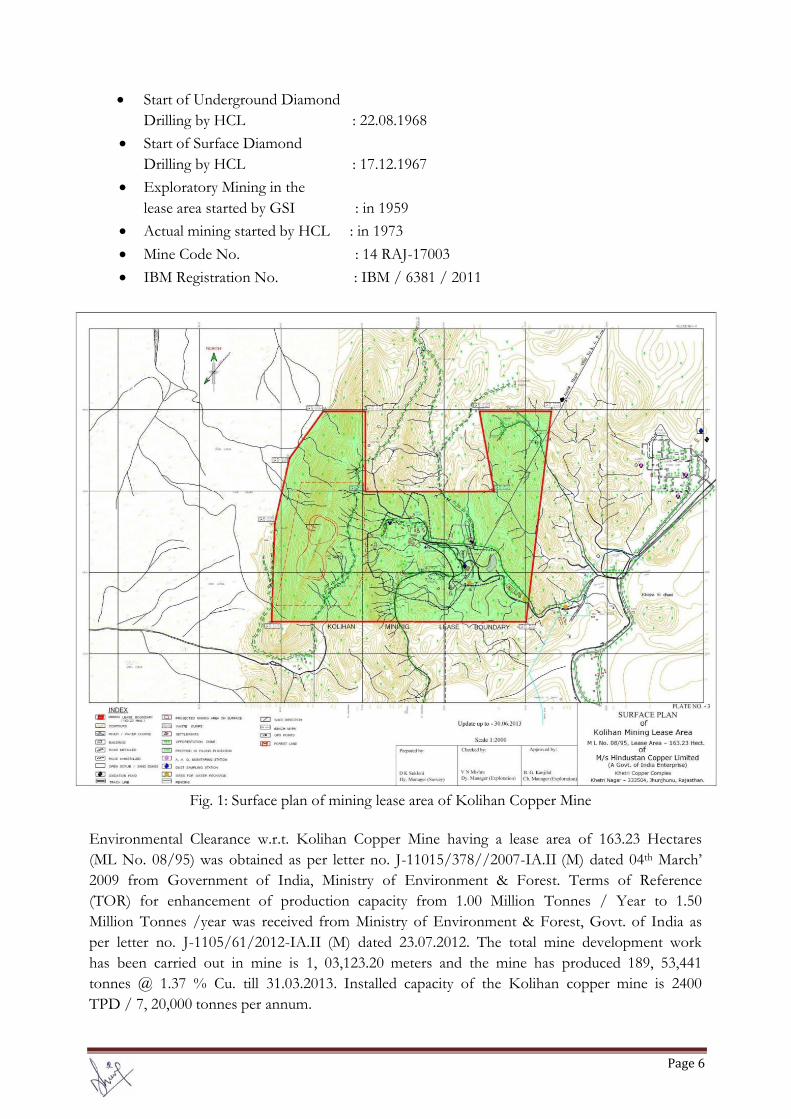
The Khetri Copper Complex has two underground working mines: Khetri Copper Mine & Kolihan Copper Mine. The Kolihan Mining Lease area is situated at the northern tip of the Khetri Copper Belt. It covers an area of 162.23 hectare. The area falls in the Survey of India Topo sheet No. 44 / P16. Main hill ranges in the lease hold area strikes NNE-SSW located at the western side of half of the area. The hill ranges contain the host rock of copper mineralization. The western slope of the hill is steep while the eastern slope is relatively gentle. The lease-hold area is marked on the Survey of India Toposheet no.44P/16 in 1:50000 scale.
Figure 1 shows surface plan of mining lease area of Kolihan Copper Mine. The details of the mine are as given below:
Start of 424m RL Adit : July’1966
Declared as mine : 06.12.1966
Start of 486 m RL Adit : 03.01.1967
Page6
Start of Underground Diamond Drilling by HCL : 22.08.1968
Start of Surface Diamond Drilling by HCL : 17.12.1967
Exploratory Mining in the lease area started by GSI : in 1959
Actual mining started by HCL : in 1973
Mine Code No. : 14 RAJ-17003
IBM Registration No. : IBM / 6381 / 2011
Fig. 1: Surface plan of mining lease area of Kolihan Copper Mine
Environmental Clearance w.r.t. Kolihan Copper Mine having a lease area of 163.23 Hectares (ML No. 08/95) was obtained as per letter no. J-11015/378//2007-IA.II (M) dated 04th March’ 2009 from Government of India, Ministry of Environment & Forest. Terms of Reference (TOR) for enhancement of production capacity from 1.00 Million Tonnes / Year to 1.50 Million Tonnes /year was received from Ministry of Environment & Forest, Govt. of India as per letter no. J-1105/61/2012-IA.II (M) dated 23.07.2012. The total mine development work has been carried out in mine is 1, 03,123.20 meters and the mine has produced 189, 53,441 tonnes @ 1.37 % Cu. till 31.03.2013. Installed capacity of the Kolihan copper mine is 2400 TPD / 7, 20,000 tonnes per annum.

Page7
The present infrastructure facilities of the mine can facilitate the ore production up to “0” mRL only. Now, in 3rd phase, there is plan to extent the infrastructure facilities to produce up to (-) 120 mRL. Accordingly, ore pass & shafts will be sunk (from surface to -220 mRL) along with other related peripheral facilities like crusher, surge bin etc. to cater the production requirement up to (-) 120 mRL. After completion of 3rd p h a s e , the mine will have appropriate hoisting capacity & more nos. of levels to work with and it will produce 1.50 Million Tonnes per year for which necessary infrastructural development are being started from the year 2013-14 onwards though, with gradual increase in production capacity Kolihan Copper Mine will achieve 1.50 Million Tonnes per year production from year 2023-24. 2.1 Location & Accessibility The Kolihan Copper Mine is well connected by metalled road. The nearest railway station is Nizampur on Rewari-Jaipur section (North Western Railway) & another is Chirawa (30 Kms) on Loharu-Jaipur section (North Western Railway). Latitude : N 28 00' 46"- N 28 01' 22" Longitude : E 75 45' 32"- E 75 47' 12" 2.2 Land Use Pattern The land use of 163.23 hectare lease hold area is as given in Table 1. Out of 163.23 ha of mining lease area 161.83 ha is forest land and remaining 1.40 ha is non-forest land. The Ministry of Environment and Forest, GOI, vide letter no 8-5/97-FC, dated 10-2-1996 has accorded approval to Hindustan Copper Limited for diversion of 167.707 ha (161.83 ha within mining lease are and 5.88 ha outside the mining lease) of forest land for non-forest use. The land use of 163.23 ha of lease hold area has been calculated in accordance with the actual use for different purpose. Table 1: The land use pattern of 163.23 hectare (ha) lease hold area of Kolihan Copper Mine
S. No. Land use Area in Hectare (ha)
% of total area
1 Area excavated (excavation for adits, & decline)
0.938 0.57
2 Waste Dump 1.64 1.00 3 Mineral Storage / Stockpile 0.30 0.20 4 Infrastructure / Buildings etc. 4.07 2.49 5 Roads 1.59 1.00 6 Railway (Surface track) 0.11 0.07 7 Subsidence 6.81 4.17 8 Green Belt 2.05 1.30 9 Undisturbed 145.722 89.20
Total 163.23 100 Only 15.458 hectares i.e. 9.47% of total lease hold area has been utilized for mining and related activities. Remaining 147.772 hectares i.e.90.53% area still exists in its natural way. In Kolihan mining lease area, being underground mining operations, excavation of area and top soil removal is nil. Town ship, tailing ponds and concentrator plant are outside the mining lease area and these are managed properly by keeping in view the environmental aspects.

Page8
2.3 Mining Method The Kolihan Copper Mine has been developed over a strike length of 700 metres and has eight levels at vertical interval of 60 metres viz. 424, 364, 306, 246, 184, 124, 64 and 0 meter reduced levels (mRL). The numbers indicate the height of the respective level above Mean Sea Level. The upper four levels viz. 424, 364, 306 and 246 mRL are exhausted and topmost three levels are isolated from rest of the mine. Production is going on in two levels namely 184, 124 mRL and mine development is going on at four levels 184, 124, 64 & 0 mRL. Stope development in strike extension at 306 mRL and 246 mRL is also being planned to increase stope availability.
Kolihan mine was designed to produce 2500 tpd at the commissioning stage and consistently achieved up to 2000 tpd. This mine has the limitation of ore hoisting capacity and waste hoisting capacity. Due to low realization of copper price during in late nineties and poor financial performance of company, mine development was not taken care properly and maximum possible ore has been depleted with minimum mine development, causing decreasing trend in mine output. The ore body at Kolihan Copper Mine is wide and over a strike length of 600 m it has got 5.0 million tonnes of ore reserves per level and in lower levels at both the flanks it is increasing by about 200 m. For increasing the capacity of Kolihan Copper Mine it is proposed for construction of production shaft from surface to (-) 220 mRL and having a capacity to hoist 3000 TPD. The existing shaft will be utilized for hoisting the ore 2000 TPD. The total capacity of hoisting will be 5000 TPD from Kolihan Mine. 3. SUBSIDENCE MONITORING 3.1 Available Control Data The whole work was based on the coordinates of two control points, supplied by the Survey Office of Kolihan Copper Mine as listed in Table 2. Table 2: Coordinates of Control Points used as baseline as supplied by Survey office of
Kolihan Copper Mine. Sl. No. Station ID Description
Northing/Latitude, Y (m)
Easting/ Departure, X (m)
Elevation/ RL, Z (m)
01. T16 Marked on the top of Concrete cast on Hill 1 at Eastern side 3554.126 6224.569 471.26
02. T26 Marked on the top of Concrete cast on Hill 2 at Eastern side 3767.741 5783.804 475.7
The coordinate of T26 and the bearing of baseline T26-T16 were used as initial survey data.
Page9
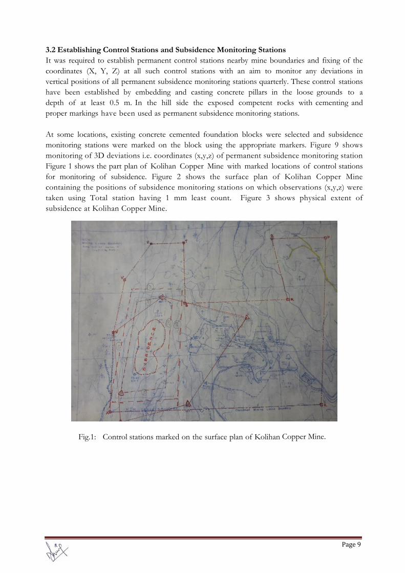
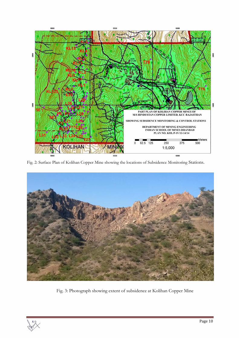
3.2 Establishing Control Stations and Subsidence Monitoring Stations It was required to establish permanent control stations nearby mine boundaries and fixing of the coordinates (X, Y, Z) at all such control stations with an aim to monitor any deviations in vertical positions of all permanent subsidence monitoring stations quarterly. These control stations have been established by embedding and casting concrete pillars in the loose grounds to a depth of at least 0.5 m. In the hill side the exposed competent rocks with cementing and proper markings have been used as permanent subsidence monitoring stations. At some locations, existing concrete cemented foundation blocks were selected and subsidence monitoring stations were marked on the block using the appropriate markers. Figure 9 shows monitoring of 3D deviations i.e. coordinates (x,y,z) of permanent subsidence monitoring station Figure 1 shows the part plan of Kolihan Copper Mine with marked locations of control stations for monitoring of subsidence. Figure 2 shows the surface plan of Kolihan Copper Mine containing the positions of subsidence monitoring stations on which observations (x,y,z) were taken using Total station having 1 mm least count. Figure 3 shows physical extent of subsidence at Kolihan Copper Mine.
Fig.1: Control stations marked on the surface plan of Kolihan Copper Mine.
Page10
Fig. 2: Surface Plan of Kolihan Copper Mine showing the locations of Subsidence Monitoring Stations.
Fig. 3: Photograph showing extent of subsidence at Kolihan Copper Mine

Page11
3.3 Quarterly Monitoring of Subsidence over Established Subsidence Monitoring Stations In order to trace any visible movement of subsidence monitoring stations established during the phase I of the study, the 3D coordinates (X,Y,Z) of all such subsidence monitoring stations were observed using EDM traversing having least count of 1mm. The stations T16 & T26 as mentioned above were considered as base stations lying outside subsidence zone. The coordinates of control stations T16 & T26 were made available by the survey officer of Kolihan Copper Mine. Figure 4 show monitoring of 3D deviations i.e. coordinates (X, Y, Z) of permanent subsidence monitoring station in a grid pattern.
Fig. 4: Monitoring of subsidence over the permanent subsidence monitoring station on hilltop using
Prism monitoring (EDM) keeping total station on control station on Hill in non-mining area 3.4 Procedure adopted
A Precise EDM closed traverse was carried out to join all the control stations for the purpose of monitoring subsidence on all subsidence monitoring stations set in a grid pattern all along the subsidence area of Kolihan Copper mine from control station. The horizontal angles were observed upto 1” least count and distances and coordinates upto 1 mm with Electronic Reflectorless Total Station for establishing X, Y and Z coordinates for all the new control stations and subsidence monitoring stations. During the phase II (Q3), these all subsidence monitoring stations were observed for possible movement using total stations from the known control stations established earlier in non-subsidence zone.
Page12
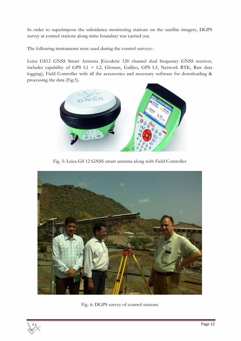
In order to superimpose the subsidence monitoring stations on the satellite imagery, DGPS survey at control stations along mine boundary was carried out. The following instruments were used during the control surveys:- Leica GS12 GNSS Smart Antenna [Geodetic 120 channel dual frequency GNSS receiver, includes capability of GPS L1 + L2, Glonass, Galileo, GPS L5, Network RTK, Raw data logging), Field Controller with all the accessories and necessary software for downloading & processing the data (Fig.5).
Fig. 5: Leica GS 12 GNSS smart antenna along with Field Controller
Fig. 6: DGPS survey of control stations

Page13
Fig. 7: Position of control stations (surveyed with DGPS) shown on satellite imagery
All together 10 boundary points/control stations were surveyed for fixing of DGPS coordinates of these control stations. Table 5 lists the WGS84 coordinates of the some of the control stations used for DGPS survey. Table 5: WGS84 coordinates of the some of the control stations used for DGPS survey.
STN LATITUDE LONGITUDE POSITON QUALITY
BPF 280 00' 41.24651" N 750 46' 28.82549" E 0.0002
MB11 280 04' 48.17539" N 750 49' 20.34717" E 0.0001
P5 280 00' 52.94183" N 750 46' 32.84360" E 0.0005
PB1 280 05' 40.32484" N 750 49' 30.55207" E 0.0003
PB5A 280 05' 15.20756" N 750 48' 54.31244" E 0.0004
PB5C 280 05' 35.51335" N 750 49' 17.67812" E 0.0002
SP1 280 00' 56.07326" N 750 46' 33.03508" E 0.0004
T1 280 04' 18.79635" N 750 48' 40.93726" E 0.0083
TL 280 04' 43.14887" N 750 48' 36.48330" E 0.0003
TS46A 280 00' 47.04175" N 750 46' 36.97357" E 0.0003
These control stations were used to geo-reference the satellite imagery for showing the subsidence monitoring stations. Possibilities of use of DInSAR for subsidence monitoring over a large area under such a difficult terrain is being explored.

Page14
4. RESULT
The computations of the coordinates [X, Y, Z] of control stations and subsidence monitoring stations established through closed EDM polygonic traverse circuit were carried out through computer programmes. The computations of the coordinates [X,Y,Z] of control stations established through closed EDM polygonic traverse circuit is given in Annexure – I. The computations of the coordinates [X, Y, Z] of all the available Subsidence Monitoring Stations which were monitored during phase II (Q3) is given in Annexure – II A plan on a suitable scale showing the positions of control stations and Subsidence Monitoring Stations in a grid system is also submitted with the reports at Annexure – III and Annexure – IV. Annexure V shows subsidence monitoring stations superimposed on the satellite imagery. 5. SUBSIDENCE CONTROL AND PREVENTION The following measures as listed below can be effective in the Ground Surface stability of the Subsidence zone at the Kolihan underground mine.
Selection of appropriate stoping method depending on the specific nature of potential future ore bodies, and management techniques can be used to ensure ground surface stability.
Geotechnical mapping of ore development drives and detailed characterisation of the rockmass prior to stoping operations to ensure stable stoping spans.
Limiting open stope spans in-spite of the rock mass design charts indicating possibility of larger spans.
Reducing stope spans in areas identified with poorer ground conditions to ensure overall stability during the short cycle life of a stope.
Tightly controlling mining spans in the upper levels of the mine such as the use of the Backfilling mining method in the upper section of the mine.
Prompt back-filling of all stope voids in the mining cycle and some development drives where necessary to ensure long-term stability.
Selective cable bolting of discrete structures to improve stope stability where structures may affect stability.
Leaving a sufficiently sized remnant pillar to separate new workings from the ground surface
Sufficient parting will be left between surface and the stoped out area as a measure against subsidence. Besides, parting among lenses will provide natural support to the strata.
Post-mining stabilization techniques include backfilling, grouting, excavation and fill placement, and blasting might be adopted.
Ongoing use of advanced numerical modelling services calibrated with data collected from the monitoring strategy for continued updating of modelling forecasts.
Sterilisation of ore and/or premature cessation of mining if unacceptable levels of ground surface subsidence are forecasted with numerical modelling or measured through the monitoring strategy

Page15
Monitoring the rock mass response to mining activities may take the form of:
Use of instrumentation such as multi-point borehole extensometers, vibrating wire stress meters, and survey traverses underground to measure displacement of the rockmass during mining.
Installation of a micro-seismic monitoring system to measure and monitor ground noise activity and rock mass and structure response to mining.
Periodic use of physical monitoring techniques such as surface network of survey stations to measure displacement above the proposed underground Mine using prism monitoring (EDM), interferometric synthetic aperture radar (InSAR/DInSAR) satellite technology, GPS observations etc. to determine location, magnitude and rate of ground surface settlement or subsidence related to mining activities.
6. CONCLUSIONS
The position of subsidence monitoring stations (as established through control survey during the first phase of traverse survey) with respect to available control stations were also measured during the phase II (Q3) of subsidence survey with precise Total Station.
The variations of R.Ls. are insignificant as reflected from Annexure – II. There are some significant variations in the levels at few stations (more than 5 mm) among first, second and third phases of data measured in between December 2014 – August 2014, which may be attributed to measurement variations/pillar disturbances or subsiding of ground.
The amount of subsidence has been observed as a direct function of time. Even in cases where vein deposit mining methods are employed in competent rock at great depths with low extraction ratios, the surface expression of subsidence is not eliminated, but may not appear for some time.
Regular monitoring of subsidence on the surface over and around the working area and impact on natural drainage pattern, water bodies, vegetation, structures etc. should be continued till movement is ceased completely.
As evident from Figure 3, the entire area under subsidence is on a specific hill region falling under forest area free from forest cover, water bodies, surface structures, and habitants. In order to comply the guidelines of MOEF, GOI, Indian School of Mine, Dhanbad has been doing quarterly monitoring of Subsidence Monitoring Stations (approx. 100-120 stations) in a grid pattern using state-of-the-art EDM (ETS) instruments at Kolihan Copper Mine as per the above-mentioned methodology for two years w.e.f 07.08.2013. The quarterly reports of monitoring are being submitted to HCL at the end of each monitoring for undertaking the measures to control the surface subsidence if any.
RECOMMENDATIONS
o Measurement of ground level constitutes baseline data for subsidence study and hence it is therefore recommended for periodical monitoring of the ground levels at the identified control stations during the operational phase.
o It has been reported that land subsidence can be caused by large scale open stope underground mining and in certain parts of the world, subsidence has actually been

Page16
observed. Of course there can be other causes, natural as well as man-made for land subsidence.
o The stations established during EDM survey carried out by ISM Survey team are very precise which involves the efforts, time and funds; therefore it is recommended these stations should be preserved carefully without causing any ground disturbance at the surroundings.
o Suitable arrangements may be made so that these stations should not be disturbed by someone.
REFERENCES
Bahuguna, P. P. (1995), Subsidence studies in Indian coalfields by a semi empirical Approach, Land Subsidence (Proceedings of the Fifth International Symposium on Land Subsidence, The Hague, October 1995). IAHS Pubi. no. 234, Pp 127-133
Bahuguna, P. P. (1993), Development of mine subsidence prediction model for Indian Coalmines, PhD Thesis, Deptt. of Civil Engg, University of Roorkee, India.
Bahuguna, P. P. (1994), Subsidence Monitoring, Proceedings of 2nd Indian Conference on Coal Mine Surveying, ICCMS-94.
Bahuguna, P.P. and Srivastava, A.M.C., Saxena, N.C.(1991), A Critical Review of Mine Subsidence prediction Methods. Mining Science Technology. Pp.369-382. Vol. 13. No.3. Dec. 1991.
Duk-Won Park (2004), Paper on Subsidence Simulation using Laser
Optical Triangulation Distance Measurement Devices, Presented in 6th North America Rock Mechanics Symposium.
Fulton A (2005-2006), Study on Land subsidence: What is it and why is it an important aspect of groundwater Management, Article No. 3, in the discussion on the topic of ground water and wells in Northern Sacramento Valley.
Mine Subsidence. Singh, Madan M. ed. Society of Mining Engineers, Littleton, CO, 1986. AIME. Pp.73-143.
Mining Environmental Handbook. Marcus, Jerrold J. Imperial College Press, London. 1997.
Prokopovich, N. P. Environmental Geology. Betz, Fredrick Jr. ed. (1 9 7 2), Land
Subsidence and Population Growth. Reprint from 24th Intern. Geol. Congr. Proc., 13, 44-54.
SME Mining Engineering Handbook (1992). Hartman, Howard L. Society of Mining, Metallurgy and Exploration, Inc. Port City Press, Baltimore
Soliman, Mostafa M. et al. (1998), Environmental Hydrogeology. CRC Press LLC, 1998. Pp81-101.
Whittaker, B. N., and Reddish, D.J. (1989), Subsidence—Occurrence, Prediction and Control: Elsevier, 528.