substation #12 instructions for assembly of the ho...
TRANSCRIPT

1
Substation #12Instructions for Assembly of the HO scale kit.v1.1
Kit Contents:33 each .090" Acrylic parts1 each .020" Adhesive backed styrene parts sheets11 each Cast 3D parts2 each .060 x 10" Styrene round rod1 each Paper window shades19 each .060" Clear window glazing2 each Tar paper roofing material sheetInstructions with diagrams
About the Kit
Substations convert high voltage electricity to lower voltage electricity. They can also be used toregulate or distribute electricity on a grid. Our kit is based on a substation found along the C.M. & St.P. Ry., also known as the Milwaukee Road. It provided regulated electrical power tothe catenary lines on the railroad. It can be used for many other applications as well, many largeindustries would require a substation.
Thank you for purchasing this kit. Please read these instructions completely before beginning andtake your time. Allow parts to dry after painting or gluing and do not try to build this in onenight.
Parts are labeled in the instructions inside parentheses. Many parts have engraved details onthem. Be sure that these are facing out when gluing the parts together. It is easy to install thesebackwards by mistake.
Practice gluing the acrylic together if you have never done it before.
If by chance a part is missing or broken, please write us indicating the kit name and part numberand we will send you a replacement.
Please note that parts of the kit have been painted gray in the assembly photos so that new partscan easily be seen and identified. This is only for ease of identifying parts and seeing themclearly in the photos. We recommend gluing all parts together prior to painting unless otherwisenoted. Pre-production models were used in these instructions, your parts may vary slightly.
You will need the following items to assemble your model: Sharp hobby knife, file, small drillbits, pin vice, paint (see “Painting Your Model”), paint brushes, glue (see “Gluing Acrylic”),modeling putty, masking tape.

2
Gluing Acrylic
Always glue acrylic in a well-ventilated area, and read the glue manufacturer’s label forinstructions.
We recommend using Scalecoat brand “Probond”, “Tenax-7R”, Plastruct brand “BondeneSolvent Cement” or “Plastic Weld Cement”. Most hobby shops carry these products. Or theymay be ordered directly from the manufacturer.
Acrylic must be glued together using a solvent that will melt the two edges and literally fusethem together. To do this, place the two pieces to be joined together and run a bead of solventdown the edge. Capillary action will suck the solvent into the joint and after several seconds thepieces will be fused. After only a few minutes the pieces will be strong enough to work with. Thebond will be completely dry within twenty-four hours using the above-mentioned products.Solvent can be dispensed two ways.
Typically the solvent comes in a small bottle with a brush in the lid. The brush allows you todispense a drop or two of solvent at a time.
You may want to use a polyethylene bottle or syringe with a blunt needle dispenser. This allowslarger amounts of solvent to be dispensed quickly and cleanly. Be sure the bottle you are using isapproved for the solvent you are using or you may melt through it. These bottles may bepurchased from CMR.
Super GlueCyanoacrylate (CA) Super Glue
Parts that are not plastic or are painted prior to gluing must be glued together using a non solventbased glue. This means the parts are held together by the glue and not the process of fusing orwelding them together with solvent. For this we recommend using CA where noted in theinstructions.
Craft Glue
Some parts are easier to glue using craft glue such as “Sobo”. We use craft glue to stickpreviously painted parts together when we want a little working time.

3
Note on Tabs
Sometimes it is necessary to sand or file the tabs slightly in order to get them to seat themselvesinto the slots. This is due to slight variations in acrylic thickness. If the tabs are not fitting intothe slots properly, you may need to file them back at an angle to fit properly.
Note on Castings
Castings will need to be cleaned up with fine sand paper or a small jewelers file. Washthoroughly prior to painting.
Preparing Your Model for Painting
We recommend lightly sanding all parts to remove the raised edge created during the lasercutting process. In order to hide the seams we recommend using “hobbyist putty” such as GreenSquadron modeling putty. Do this in a very well-ventilated area. Apply the putty over the seamsand allow to dry overnight. Once the putty has dried, place a sheet of fine sandpaper on a flatsurface and sand smooth. You may need to apply a second coat of putty and sand again.
Painting Your Model
After building each unit we primed our building with Krylon Ruddy Brown spray paint.
For our building paint scheme, we used acrylic hobby paints which are available in most hobbystores.
We painted the building brick color. To create the mortar between the bricks the building unitswere then laid flat with a wall facing up and a concrete wash (water and 15% paint) was appliedand allowed to dry. The unit was then rotated to the next wall and the process was repeated, andso on.
The concrete base was painted a concrete color.
Prior to installing the windows the building was air brushed with a grimy black to create aweathered look.
The window frames were painted flat black with spray paint (do not spray the adhesive backing).
The roof was painted black.
The insulator assemblies were primed, painted black and then detail painted by hand . Theinsulators were painted green and then dry brushed with a lighter green to highlight the edges anddetails.
4
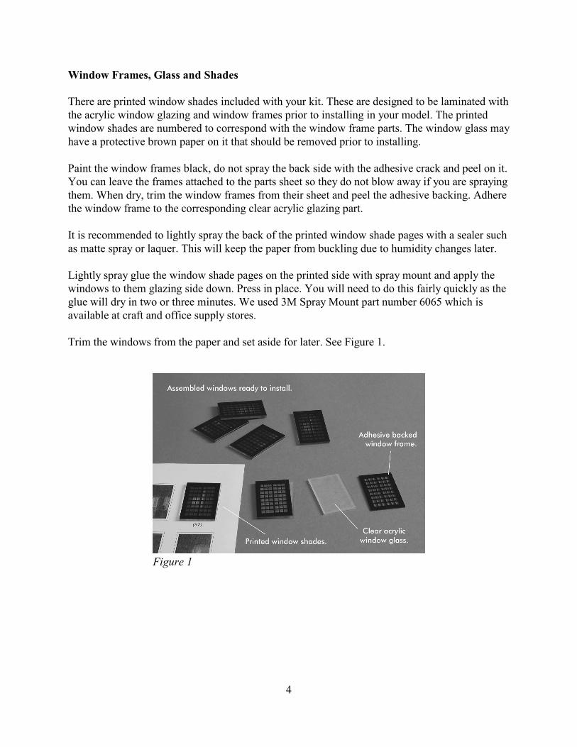
Window Frames, Glass and Shades
There are printed window shades included with your kit. These are designed to be laminated withthe acrylic window glazing and window frames prior to installing in your model. The printedwindow shades are numbered to correspond with the window frame parts. The window glass mayhave a protective brown paper on it that should be removed prior to installing.
Paint the window frames black, do not spray the back side with the adhesive crack and peel on it.You can leave the frames attached to the parts sheet so they do not blow away if you are sprayingthem. When dry, trim the window frames from their sheet and peel the adhesive backing. Adherethe window frame to the corresponding clear acrylic glazing part.
It is recommended to lightly spray the back of the printed window shade pages with a sealer suchas matte spray or laquer. This will keep the paper from buckling due to humidity changes later.
Lightly spray glue the window shade pages on the printed side with spray mount and apply thewindows to them glazing side down. Press in place. You will need to do this fairly quickly as theglue will dry in two or three minutes. We used 3M Spray Mount part number 6065 which isavailable at craft and office supply stores.
Trim the windows from the paper and set aside for later. See Figure 1.
Figure 1

5
Assembly
Begin by taking the base (A) and laying it flat onyour work surface with the engraved part numberfacing up. See Figure 2 for orientation.
Insert the slots of wall (1) onto the tabs on the longside of part (A) and glue in place. Next, insert theslots of wall (2) onto the tabs on the other side ofpart (A) and glue in place. Insert the top (B)between the two walls and glue in place. Makesure the notch in (B) is oriented correctly and thatthe assembly is square. See Figure 3. Next attach the end walls (3) & (4) onto theassembly. Wall (3) will go on the side with thenotch in part (B) which allows for the window tobe installed later. Make sure to glue all the cornerstogether. Check that everything is square before theglue completely sets up. See Figure 4.
The walls should be perfectly flush on either sideat the corners. Once they are dry check that they donot extend beyond the rest of the walls. If they dosand or file them flush.
Glue wall (5) onto wall (1) and wall (6) onto wall(2). The walls should be perfectly flush on eitherside at the corners. Once they are dry check thatthey do not extend beyond the rest of the walls. Ifthey do sand or file them flush.
See Figure 5.
Figure 2
Figure 3
Figure 4
Figure 5

6
Glue wall (7) onto wall (3) and wall (8) onto wall(4). The walls should be perfectly flush on eitherside at the corners. Once they are dry check thatthey do not extend beyond the rest of the walls. Ifthey do sand or file them flush. See Figure 6.
Next build the front part of the building. It tabs intothe main building but should be built separatelyand not glued on at this time.
Lay the base (C) flat on your work surface with theengraved part number facing up. Insert the slots onthe bottom of walls (9) and (10) onto the tabs onpart (B) and glue in place. Glue the top (C)between the walls and then glue the front wall (11)in place.
Insert the tabs along the back sides of parts (9) and(10) into the slots on the main building to be surethey fit and that everything is square. See Figure 7&8.
The walls should be perfectly flush on either side atthe corners. Once they are dry check that they donot extend beyond the rest of the walls. If they dosand or file them flush.
Glue walls (12), (13) and (14) in place. Make surethey are perfectly flush all the way around. Gluethe front assembly to the main building. Set asideto dry. See figure 9 & 10.
Figure 6
Figure 7
Figure 8
Figure 9 Figure 10
7
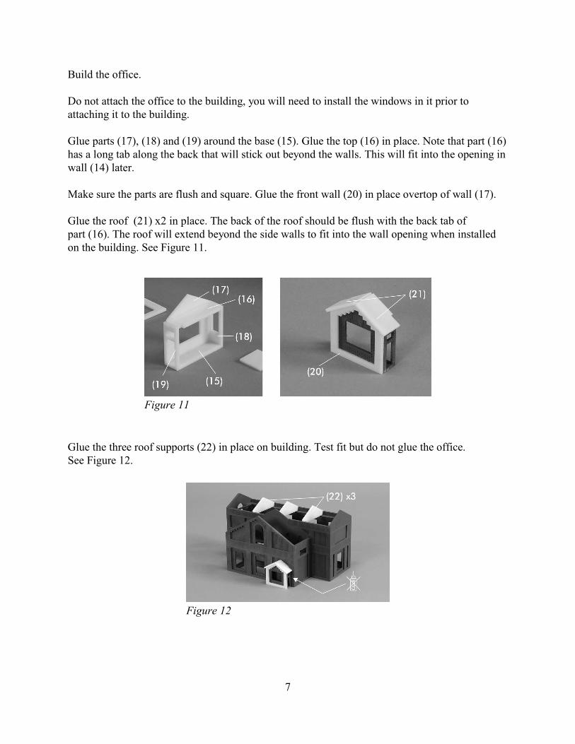
Build the office.
Do not attach the office to the building, you will need to install the windows in it prior toattaching it to the building.
Glue parts (17), (18) and (19) around the base (15). Glue the top (16) in place. Note that part (16)has a long tab along the back that will stick out beyond the walls. This will fit into the opening inwall (14) later.
Make sure the parts are flush and square. Glue the front wall (20) in place overtop of wall (17).
Glue the roof (21) x2 in place. The back of the roof should be flush with the back tab of part (16). The roof will extend beyond the side walls to fit into the wall opening when installedon the building. See Figure 11.
Glue the three roof supports (22) in place on building. Test fit but do not glue the office.See Figure 12.
Figure 11
Figure 12
8
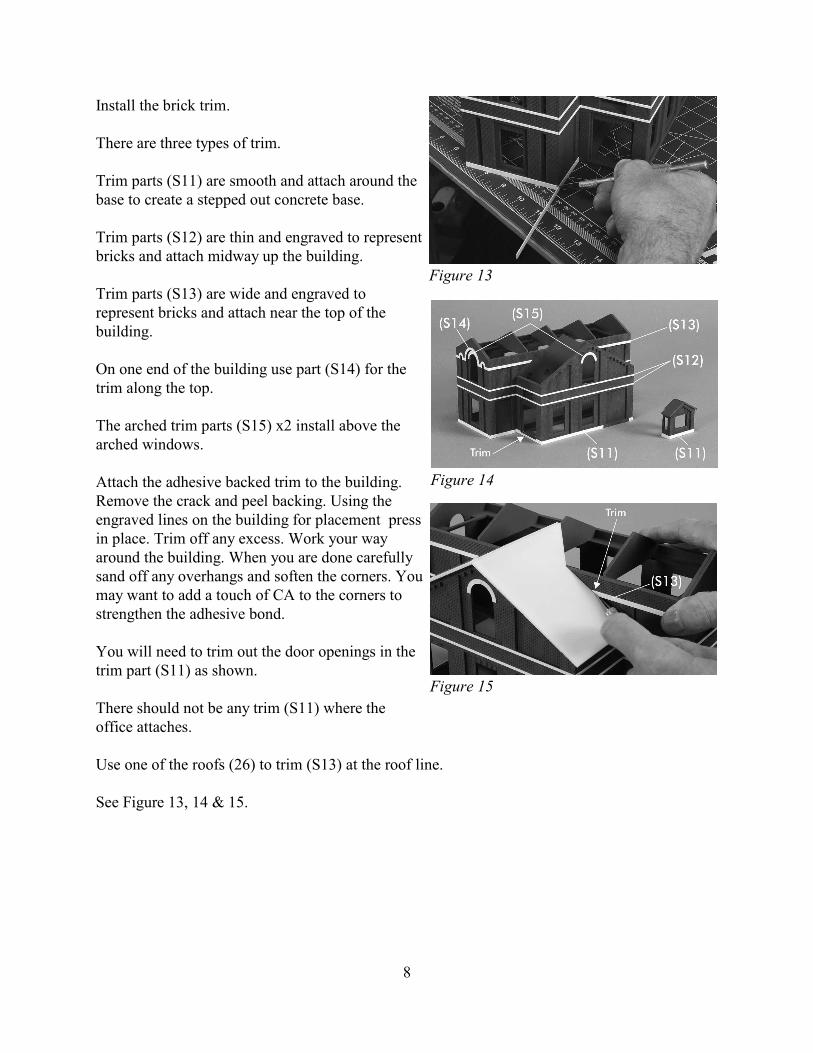
Install the brick trim.
There are three types of trim.
Trim parts (S11) are smooth and attach around thebase to create a stepped out concrete base.
Trim parts (S12) are thin and engraved to representbricks and attach midway up the building.
Trim parts (S13) are wide and engraved torepresent bricks and attach near the top of thebuilding.
On one end of the building use part (S14) for thetrim along the top.
The arched trim parts (S15) x2 install above thearched windows.
Attach the adhesive backed trim to the building. Remove the crack and peel backing. Using theengraved lines on the building for placement pressin place. Trim off any excess. Work your wayaround the building. When you are done carefullysand off any overhangs and soften the corners. Youmay want to add a touch of CA to the corners tostrengthen the adhesive bond.
You will need to trim out the door openings in thetrim part (S11) as shown.
There should not be any trim (S11) where theoffice attaches.
Use one of the roofs (26) to trim (S13) at the roof line.
See Figure 13, 14 & 15.
Figure 13
Figure 14
Figure 15

9
Paint your model.
The building walls are now complete and thestructure should be primed and painted. See theinstruction section “Painting Your Model” on page 3 for details on painting and weathering your building.
You should also paint and assemble all thewindows. See “Window Frames, Glass andShades” on page 4.
Install the window assemblies behind the appropriate wall openings. Use Super Glue (CA) toattach the window frames to the walls. Make sure to dry fit all the windows prior to gluing themin place.
Figure 16 shows you what your model should look like at this point.
Install the roof.
Lay the roof parts flat and tape together usingmasking tape as shown. Trim the tape where theroof parts will sit on the roof supports.
See figure 17.
Glue the two roof parts (26) to the building. Makesure they are up against the wall and that the trimdoes not interfere with the fit.
Next glue the long roof (24) and (25) in place. Itshould fit snug with the other roof.
Use the .060 rod to fill the gaps between the roofparts at the peak. Install rod in the office roof aswell.
See Figure 18.
Sand and clean up any imperfections. You mightwant to fill the ends of the peaks with modelersputty so there are not any gaps.
Figure 16
Figure 17
Figure 18

10
The roof has a tar paper surface. Tar paper materialis included in your kit. It is adhesive backed paper.
Begin by using one of the thin strips with anengraved line down the center. Gently crease italong the center, remove the adhesive backing andrun it down the two roof valleys. Trim it to a cleanedge with a sharp hobby knife. Keep any extramaterial left over, you will need it later for the roofcap. See Figure 19.
Next begin applying the roof sheets. Begin at thebottom of the roof and work your way up. There isan engraved line on the paper. This should be at thetop of the sheet and is used to align the next sheetto. There will be about an 1/8" overlap. If you runshort on a row just continue with a new sheet,seams are okay.
When you get a roof sections covered trim off theoverhanging bits and clean up the cut lines beforemoving on to the next roof. When you have all theroofs done use the thin strips to create a roof cap.See Figure 20.
When the roof is completed it should be sealed with mat spray before painting. If there are anybits sticking up or not adhering properly you can apply a little CA under the tar paper. Press itdown and wipe off any excess glue.
Do the same for the office roof.
When dry paint the roof black.
Figure 19
Figure 20

11
Build the insulators.
Clean up the insulator castings. Youwill need to drill out a small hole inthe top of each large insulator toaccept a piece of wire. See Figure 22.
There are two insulator assembliesthat attach to the main part of thebuilding. Each of these are made upof a insulator hood and three largeinsulators. Glue the insulators to thehood. The small hole in the end ofeach insulator should face the same direction.See Figure 21.
Build the wall insulator assembly.
Glue the three insulator castings to part (22) asshown. See Figure 23.
Prime and paint the insulator assemblies asdescribed in the “Painting Your Model” section ofthe instructions found on page 4.
Figure 21
Figure 22
Figure 23

12
Final assembly of the building.
At this point you have all the components of thebuilding assembled and can put them together tofinish your model. You should have the wallspainted and weathered with the window frames,glazing and shades installed. The office should beassembled in the same manner. The roofs shouldbe installed with the tar paper on them and painted.The insulators should be assembled painted andready to install.
Glue the insulator hood assemblies onto the wallsas shown using craft glue or CA. See Figure 24.
Glue the office in place making sure it is perfectlysquare. Use the brick pattern on the main buildingas a guide. Glue the wall insulator in place abovethe vestibule as shown. See Figure 25.
Paint the name plaque (S10) concrete color andattach over the office. See Figure 25.
Your building is finished and ready to install onyour layout. You may add lights and other details.We thank you for purchasing this kit from CMRand hope that you have enjoyed building it.Be sure to see our other kits at www.cmrtrain.com.
Figure 24
Figure 25

13

14

Substation #12 Parts HO Page 1
(1)
(4)
(5) (6)
(A) (B)
(2)
(8)(3) (7)
B
B
A
A
(10)(11)(9)
(12) (13)(14)
(15)
(20)
(22)
(23) x3
(24)
(25)(26) x2
(21) x2
(16)
(17) (19)(18)
R
L
L R
L
R
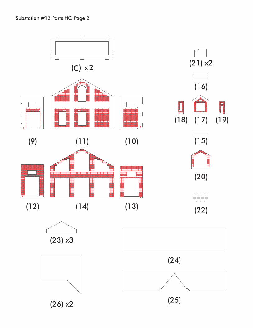
Substation #12 Parts HO Page 2
C( ) x2
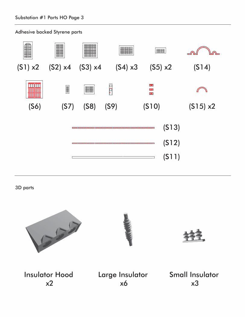
Substation #1 Parts HO Page 3
Adhesive backed Styrene parts
3D parts
(S1) x2 (S2) x4 (S3) x4 (S4) x3 (S5) x2
(S6) (S7) (S8) (S9) (S10)
(S13)
(S12)
(S11)
(S14)
(S15) x2
EAST PORTAL
DREXEL
14
12
Insulator Hood x2
Large Insulator x6
Small Insulator x3