substation automation systems – architecture and functions · substation automation systems –...
TRANSCRIPT

K02 03 20060309
© OMICRON
Substation Automation Substation Automation Systems Systems –– Architecture and Architecture and
FunctionsFunctions
Dr. Alexander ApostolovLos Angeles, CA

© OMICRON
IntroductionIntroduction
• IEC 61850 is an approved international standard
• Hundreds of substations in service• Different levels of implementation• Mostly single vendor systems• Requires answers to many questions
© OMICRON
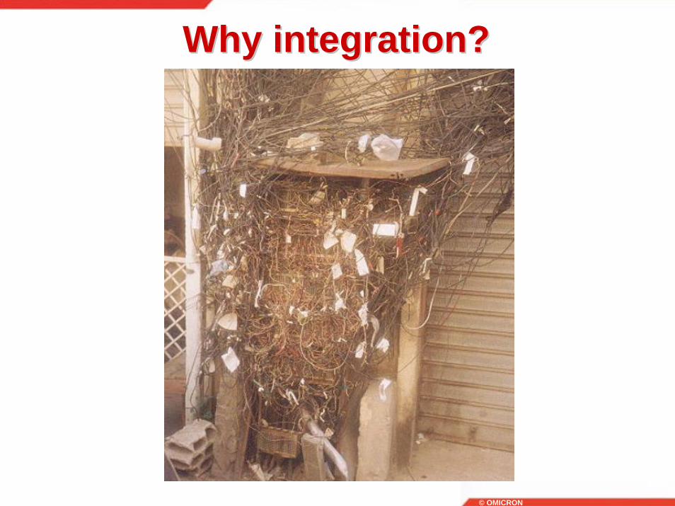
Why integration?Why integration?

© OMICRON
The Integration Process The Integration Process

© OMICRON
The Secret to SuccessThe Secret to Success
© OMICRON
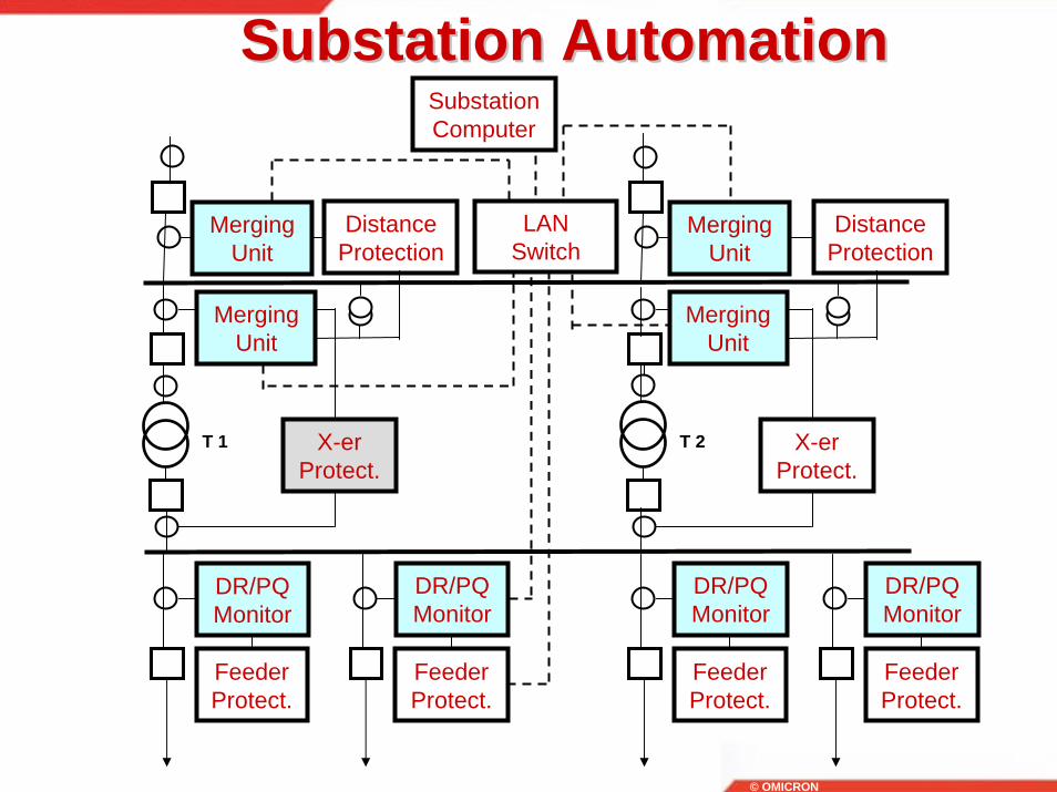
Substation Automation Substation Automation
X-erProtect.
Distance Protection
Merging Unit
X-erProtect.
Merging Unit
Distance Protection
Merging Unit
Feeder Protect.
DR/PQ Monitor
Feeder Protect.
DR/PQ Monitor
Feeder Protect.
DR/PQ Monitor
Feeder Protect.
DR/PQ Monitor
T 1 T 2
Merging Unit
Substation Computer
LAN Switch

© OMICRON
What is SAS?What is SAS?
• Substation automation can mean different things to different electric utilities.
• Adding a supervisory control and data acquisition (SCADA) sys-tem for remote monitoring and control to a traditional substation with mimic panels and an annunciator.
• Replacing the mimic panel and annunciator with a station human machine interface (HMI).

© OMICRON
What is SAS?What is SAS?
• Replacing all interlocks, cutouts and other controls so that all station control is performed and monitored using a combination of microprocessor based relays, substation controllers and HMIs.
• Actual station automation, including such items as automatic voltage control, power fail actions, intelligent load transferring between stations, load tap changer control and other automated routines.
© OMICRON
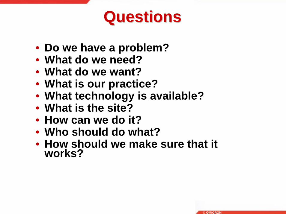
QuestionsQuestions
• Do we have a problem?• What do we need?• What do we want?• What is our practice?• What technology is available?• What is the site?• How can we do it?• Who should do what?• How should we make sure that it
works?

© OMICRON
Communication in SubstationsCommunication in SubstationsSUBSTATION COMMUNICATION
Physical link Protocol
RS485 - copper
RS232 - copper
Ethernet - copper
Ethernet – optic
SPA
Courier
Profibus . . .
MODBUS
DNP3
IEC 60870
Proprietary
Open
© OMICRON
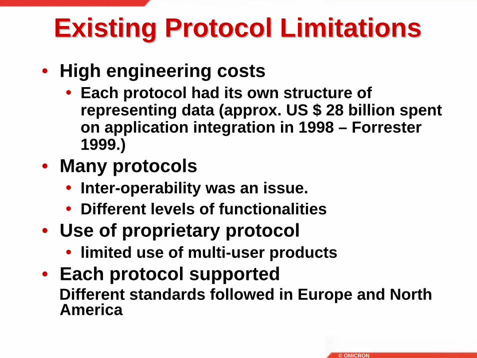
Existing Protocol LimitationsExisting Protocol Limitations• High engineering costs
• Each protocol had its own structure of representing data (approx. US $ 28 billion spent on application integration in 1998 – Forrester 1999.)
• Many protocols • Inter-operability was an issue.• Different levels of functionalities
• Use of proprietary protocol • limited use of multi-user products
• Each protocol supported Different standards followed in Europe and North America

© OMICRON“IEC61850 tutorial, CIGRE Sept 2003.” – Klaus Peter Brand
Market RequirementsMarket Requirements
• Global Market• Needs a global standard• Means a broad range of philosophies
• Mixing of devices, at least with copper cables
• Cost reduction by• Competition• Intelligence (functions)
© OMICRON“IEC61850 tutorial, CIGRE Sept 2003.” – Klaus Peter Brand
Market RequirementsMarket Requirements
• Cost reduction in• Investment• Operation
• Maintenance• Open standard, especially for the future
safe guard of investments

© OMICRON
European historical perspectiveEuropean historical perspective
• TC57 - Power systems management and associated information exchange
• IEC 60870-6 TASE 1 - ELCOM90TASE 2 - ICCP
• IEC 60870-5 101 telecontrol102 metering103 protection and control104 telecontrol over TCP

© OMICRON
European historical perspectiveEuropean historical perspective
• 1994 AHWG created 2 New Work Item Proposals:• Short term solution
• 103 = VDEW + Courier• Longer term solution
• IEC 61850

© OMICRON
American historical perspectiveAmerican historical perspective
• ANSI Market• MODBUS• MODBUS plus• DNP 3.0 level 2
• EPRI UCA 1.0 - TASE.2 (ICCP)2.0 - Substation Initiative

© OMICRON
• Utility functional requirements
• Individual solutions
• Complete solution
• New substations
• Existing substation
• Power System Integration
Substation Automation ProjectSubstation Automation Project

© OMICRON
Substation Automation ProjectSubstation Automation Project
© OMICRON
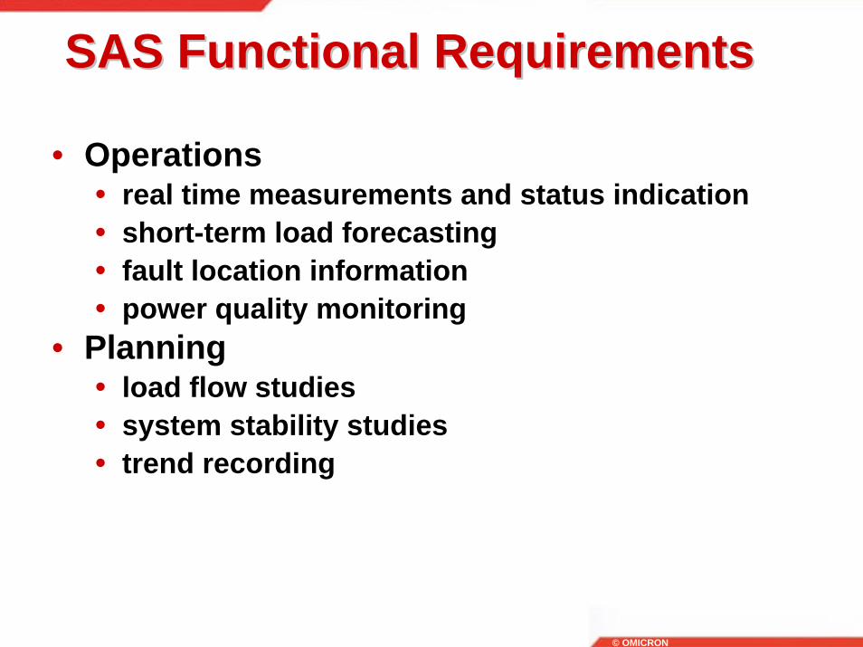
• Operations• real time measurements and status indication• short-term load forecasting• fault location information• power quality monitoring
• Planning• load flow studies• system stability studies • trend recording
SAS Functional RequirementsSAS Functional Requirements

© OMICRON
• Protection• relay settings• relay operations analysis
• Revenue metering• Analysis
• disturbance recording• waveform recording• maintenance analysis• two-ended fault locator
SAS Functional RequirementsSAS Functional Requirements
© OMICRON
IEC 61850 Standard DesignIEC 61850 Standard Design

© OMICRON
☺☺

© OMICRON
Conventional SubstationsConventional Substations

© OMICRON
Distance Protection
V, I, V0, I0,V2, I2
AnalogInputsModule
WaveformRecording
OptoInputsModule
DataBus
DistanceProtectionModule
DistanceProtectionScheme
I
RelayOutputsModule
Distance Protection ExampleDistance Protection Example
© OMICRON
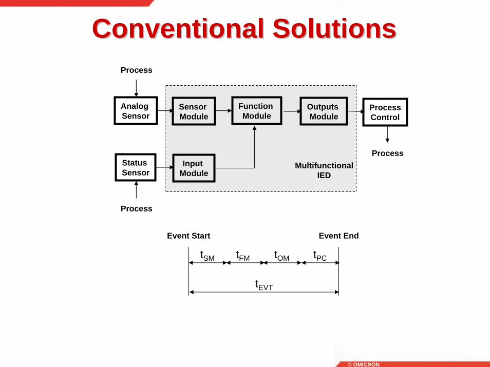
Conventional SolutionsConventional Solutions
Analog Sensor
Sensor Module
Function Module
Outputs Module
Status Sensor
Input Module
Process
Process
ProcessControl
MultifunctionalIED
Process
tSM tFM tOM tPC
tEVT
Event Start Event End

© OMICRON
IEC 61850 SystemsIEC 61850 Systems• Not just integrated devices• Functions• Communications architecture• Tools

© OMICRON
IEC 61850 Systems DevicesIEC 61850 Systems Devices• Merging Units• Binary Interface Units• Integrated Field Units• Intelligent Multifunction Devices• Communication Devices• Computers for Substation Integration• Real Time Computers

© OMICRON
IEC 61850 SystemsIEC 61850 Systems• Existing substations• New hybrid substations• Complete IEC 61850 based substations
© OMICRON
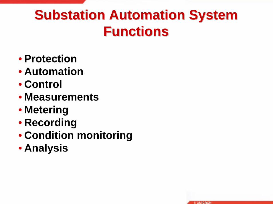
Substation Automation System Substation Automation System FunctionsFunctions
• Protection• Automation• Control• Measurements• Metering• Recording• Condition monitoring• Analysis

© OMICRON
IEC 61850 System ToolsIEC 61850 System Tools• Engineering• Configuration• Integration• Analysis• Condition monitoring• Testing• Time synchronization
© OMICRON
The IEC 61850 DifferenceThe IEC 61850 Difference
Boxes versusFunctions
© OMICRON
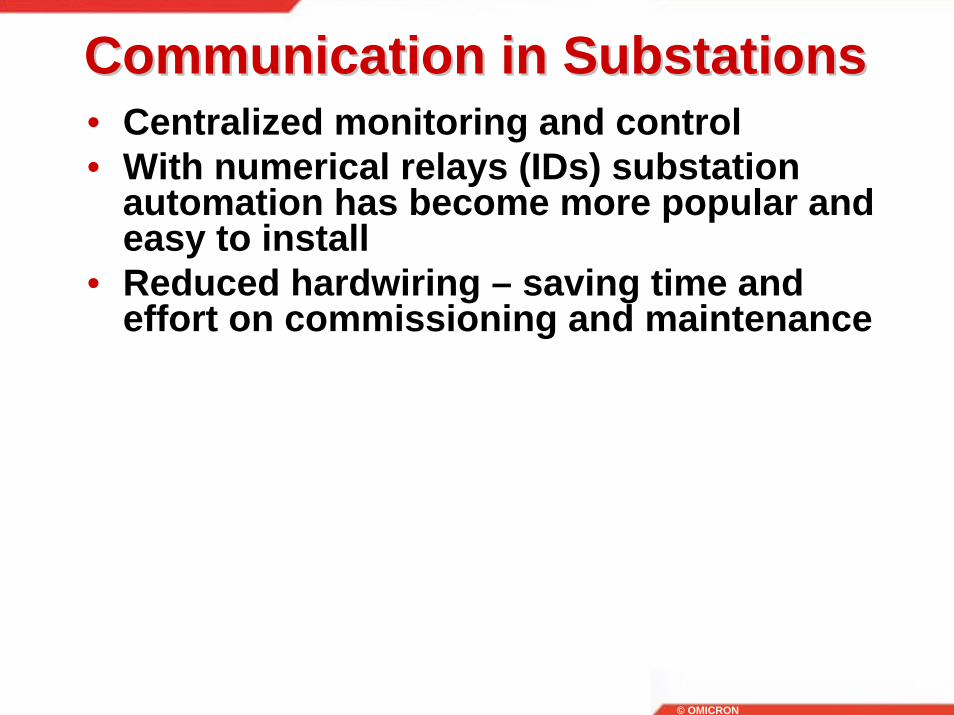
Communication in SubstationsCommunication in Substations• Centralized monitoring and control• With numerical relays (IDs) substation
automation has become more popular and easy to install
• Reduced hardwiring – saving time and effort on commissioning and maintenance

© OMICRON
Communication in SubstationsCommunication in Substations
Communications Architecture
HMI,s
SubstationController (s)
SCADA ProtocolTo IMS/SCADA
ISDISD ISDISD

© OMICRON
IEC 61850 Based ProtectionIEC 61850 Based Protection
Analog Sensor
Sensor Module
Interface Module
LANSwitch
Interface Module
Protection Module
Outputs Module
Status Sensor
Input Module
Interface Module
Process
Process
ProcessControl
Process
Merging Unit
Control Interface Unit
Protection IED
tSM tIM1 tLAN tIM2 tPM tOM tPC
tEVT
Event Start Event End
© OMICRON
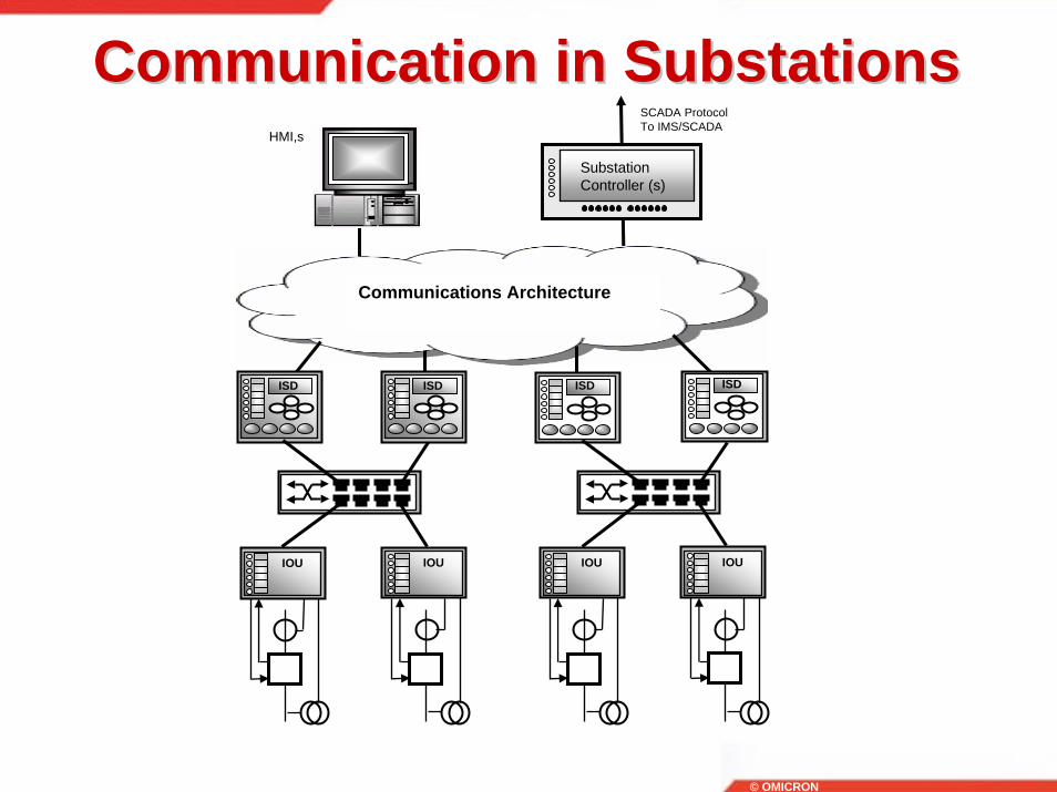
Communication in SubstationsCommunication in Substations
Communications Architecture
HMI,s
SubstationController (s)
SCADA ProtocolTo IMS/SCADA
ISDISD ISDISD
IOU IOU IOU IOU
© OMICRON
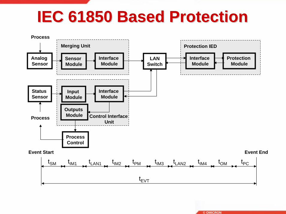
IEC 61850 Based ProtectionIEC 61850 Based Protection
Analog Sensor
Sensor Module
Interface Module
LANSwitch
Interface Module
Protection Module
Outputs Module
Status Sensor
Input Module
Interface Module
Process
Process
ProcessControl
Merging Unit
Control Interface Unit
Protection IED
tSM tIM1 tLAN1 tIM2 tPM tOM tPC
tEVT
Event Start Event End
tIM3 tIM4tLAN2

© OMICRON
System ArchitectureSystem Architecture
Substation Computer
IED IED IED IED
CT VT CT VT
Station Bus
Process Bus
Station Bus Mappings (8-1)Layered Mapping (TCP/IP)GOOSE/GSSE (Link)Time Sync (SNTP)
Process Bus Mappings (9-1,9-2)Sampled Values (Link)GOOSE/GSSE (Link)Time Sync (SNTP)

© OMICRON
Substation Automation ProjectSubstation Automation Project
Make sure you’ve got every ingredient before you start
© OMICRON
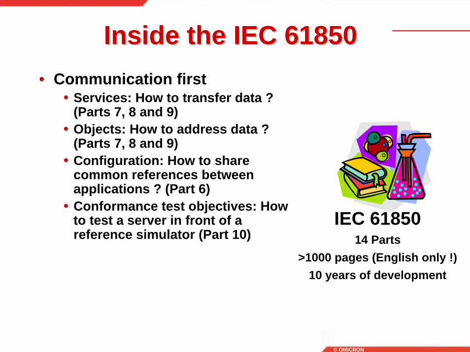
Inside the IEC 61850Inside the IEC 61850• Communication first
• Services: How to transfer data ? (Parts 7, 8 and 9)
• Objects: How to address data ? (Parts 7, 8 and 9)
• Configuration: How to share common references between applications ? (Part 6)
• Conformance test objectives: How to test a server in front of a reference simulator (Part 10)
IEC 6185014 Parts
>1000 pages (English only !)10 years of development

© OMICRON
Inside the IEC 61850Inside the IEC 61850
• Some non communication aspects
• Environmental conditions (Part 3)• Engineering requirements (Part 4)• System lifecycle (Part 4)• Informal function description (Part
5)• Connectivity between primary
devices (Part 6)IEC 61850
14 Parts>1000 pages (English only !)
10 years of development
© OMICRON
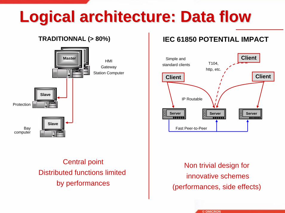
Logical architecture: Data flowLogical architecture: Data flow
Non trivial design forinnovative schemes
(performances, side effects)
TRADITIONNAL (> 80%)
Central pointDistributed functions limited
by performances
HMIGateway
Station Computer
Protection
Bay computer
Master
Slave
Slave
IEC 61850 POTENTIAL IMPACT
Client Client
IP Routable
Simple and standard clients
Fast Peer-to-Peer
ClientT104,
http, etc.
Server Server Server

© OMICRON
Outside the IEC 61850Outside the IEC 61850
• Functional specification• IED content• System architecture• Migration strategy• Non communication
configuration• Configuration & setting
management• Inter-operability tests• Project phases
What you need to add for a real project !

© OMICRON
Functional specificationFunctional specification• IEC 61850 is defining a series of function
names• “Logical Nodes”• Example: “PDIS” = Distance Protection
• Each logical node is associated to a data structure
• Example: “Str” = Start (for a protection)• The content of the data structure can be
remotely accessed• Example: Report “Str” when there is a change
• But the function itself is not defined• Example: distance algorithm is specific to each manufacturer
• The function shall be described by the project specification• Example: tripping time, number of zones, etc.

© OMICRON
Functional specificationFunctional specification
• No change for functions contained in a single IED
• Example: distance protection function• Distributed functions shall be defined
• Example: Station Wide Interlocking
• Some distributed functions are easy to identify• Interlocking, Inter-tripping, Load Shedding, Protection
Acceleration, etc.
Accurately specify distributed functionswhen mixing suppliers

© OMICRON
Functional specificationFunctional specification
• Some distributed functions require more attention
• Redundancy management, alarm management, time synchronization server, etc.
• Just replicating old schemes is likely to restrict the technology benefits
• Need to think “out of the box” to build cost effective solutions: standard clients, standard bays, new automation
Accurately specify distributed functionswhen mixing suppliers
© OMICRON
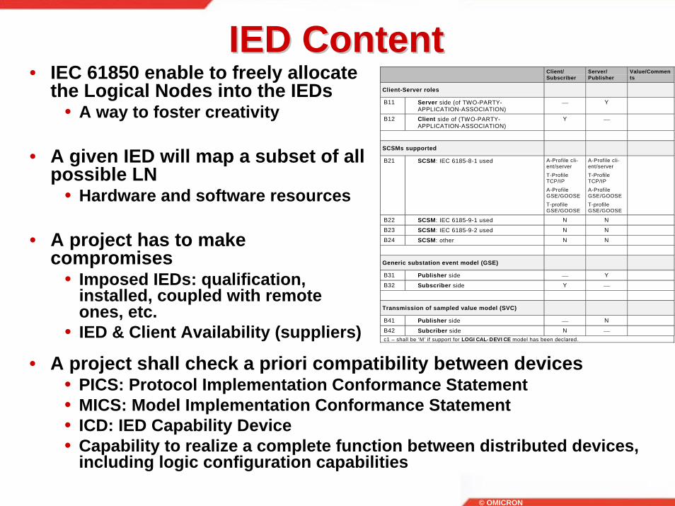
IED ContentIED Content• IEC 61850 enable to freely allocate
the Logical Nodes into the IEDs• A way to foster creativity
• A given IED will map a subset of all possible LN
• Hardware and software resources
• A project has to make compromises
• Imposed IEDs: qualification, installed, coupled with remote ones, etc.
• IED & Client Availability (suppliers)
Client/Subscriber
Server/Publisher
Value/Comments
Client-Server roles
B11 Server side (of TWO-PARTY-APPLICATION-ASSOCIATION)
⎯ Y
B12 Client side of (TWO-PARTY-APPLICATION-ASSOCIATION)
Y ⎯
SCSMs supported
B21 SCSM: IEC 6185-8-1 used A-Profile cli-ent/serverT-ProfileTCP/IPA-ProfileGSE/GOOSET-profileGSE/GOOSE
A-Profile cli-ent/serverT-ProfileTCP/IPA-ProfileGSE/GOOSET-profileGSE/GOOSE
B22 SCSM: IEC 6185-9-1 used N N
B23 SCSM: IEC 6185-9-2 used N N
B24 SCSM: other N N
Generic substation event model (GSE)
B31 Publisher side ⎯ Y
B32 Subscriber side Y ⎯
Transmission of sampled value model (SVC)
B41 Publisher side ⎯ N
B42 Subcriber side N ⎯c1 – shall be ‘M’ if support for LOGICAL-DEVICE model has been declared.
• A project shall check a priori compatibility between devices• PICS: Protocol Implementation Conformance Statement• MICS: Model Implementation Conformance Statement• ICD: IED Capability Device• Capability to realize a complete function between distributed devices,
including logic configuration capabilities

© OMICRON
System architectureSystem architecture• Nothing is defined by the IEC 61850
• Will to enable innovation• Logical architecture shall be defined
• Nominal Data flow: clients/servers and peer-to-peer, short and medium term sizing
• Non Nominal Data Flow: missing device, invalid data, performance during avalanches
• Redundancy management: client and server sides, cold/hot • Performance management: multi-cast filtering, VLAN, Clusters• Security: how to protect from external threats
• Physical architecture shall be defined• Electrical/optical• Single/redundant• Loop/Star• Ethernet Switches
System architect is required as per any Information System

© OMICRON
• Short term• Guarantee the functional consistency of the various devices
working together and the system performances• Make sure that distributed functions are fully defined and have
acceptable side effects in case of degraded situations• Mix legacy devices with new technology and define migration
paths• Manage the increasing system complexity: version, security, etc.• Design with system tests & costs in mind: interoperability,
functional validation, performances• Design and regularly improve internal generic standard
The system architectThe system architect• A (“new”) job essential for innovative
design and/or mix of different suppliers matching evolving business processes
• Both long term view (defining guidelines) and short term perspective (real projects)

© OMICRON
System Architecture vs. System System Architecture vs. System IntegrationIntegration
System Architect System Integration
• Distributed functions detailed specifications (LN mapping, LN detailed logic, report parameters, etc.)
• Migration strategy• Communication architecture• PICS and MICS of the IEDs to be used• IED preliminary choice and supplier
participation negotiation• IED paper inter-operability analysis and
validation• Performances simulations• SSD• Medium/long term evolution• Security policy• Standard packages (bay, schemes, etc.)• Project technical supervision
• Overall specification• Distributed function specification
adjustment• Overall configuration databases
and setting• Plate-form components purchasing
and assembly• Test plan/sheet/results for
nominal/degraded/performance scenario
• IED fault reports/Change report emission and supplier negotiations within the agreed frame
• Architect fault report• Version management for
HW/SW/Database per IED• FAT/SAT/Maintenance

© OMICRON
Non communication configurationNon communication configuration• System configuration aims first at
sharing the same data reference (addresses) between distributed devices
• Single data entry and (implied) consistency
• Need is increasing with the new technology
• More data are likely to be transmitted• More than client-server schemes
• System configuration goes beyond the pure communication
• Automation• Graphic• Physical I/Os
A growing requirement
Wiring
Automation
Communications
HMI

© OMICRON
Non communication configurationNon communication configuration• Most real time value are
shared between the source (IED) and GUI or Gateway
• Electrical topology is typically shared between devices and used for interlocking, voltage regulation of parallel transformers, etc.
• Substation Configuration Language (SCL) is focused on communication
• Sharing data between clients and servers, publisher and subscriber
• <20% of the system configuration
• Need for extensions
Automation description:IEC 1131-3/1499
Graphical description:SVG
CAD tools SCADA
Testing Tools
Communications &Capabilities
IEC
© OMICRON
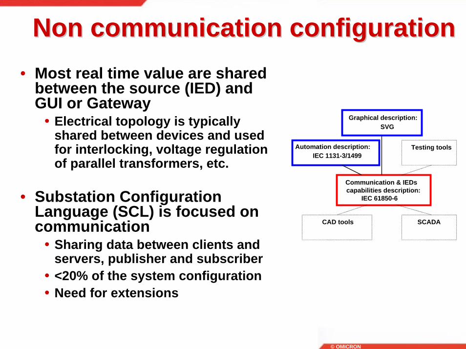
Non communication configurationNon communication configuration• Most real time value are shared
between the source (IED) and GUI or Gateway
• Electrical topology is typically shared between devices and used for interlocking, voltage regulation of parallel transformers, etc.
• Substation Configuration Language (SCL) is focused on communication
• Sharing data between clients and servers, publisher and subscriber
• <20% of the system configuration• Need for extensions
Communication & IEDscapabilities description:
IEC 61850-6
Graphical description:SVG
Automation description:IEC 1131-3/1499
CAD tools SCADA
Testing tools

© OMICRON
Configuration managementConfiguration management• Configuration management
• Capability to distribute configuration databases to the various devices and insure that their versions are consistent between them
• But a also that they are consistent with evolving hardware and software versions
• Inconsistent databases might lead to security issues (example: control the wrong circuit breaker)
• Not defined by IEC, i.e. specific to a supplier or a user
• Solution: manual process or central software client
Fixing bugs
Addingfeatures
Evolving SubstationRequirements(size, functions, etc.)

© OMICRON
Setting managementSetting management• Setting management
• Capability to adjust a device setting, i.e. local data only
• IEC is defining a change of setting group (similar to IEC 60870-5-103) but not the change of individual parameter
• IEC is defining a subset of the setting of a real device (common subset between suppliers) and is not defining how to do it (file transfer, individual setting change, device reboot, etc)
• Solution: encapsulation of the traditional setting messages over TCP/IP, in parallel to pure IEC 61850 exchanges
100 Mbps/sEthernet
IEC 61850
Independent Engineering
Encapsulated Protocols
Web-services, email

© OMICRON
Project phasesProject phases
• Need to structure the work to converge quickly• Requirements• System specification• System Architecture• Database & platform building• Inter-operability tests• Project tests
• Need to clarify the roles• End user• System architect• System integrator• Product suppliers
• A project is much more than a demo• More data will be exchanged with the new technology thus
methodology importance is increasing

© OMICRON
Conclusion: A long term Conclusion: A long term investment investment
Scalable systems
Benefits
Investmentphase
TraditionalTechnology
QUICKHITS
GOOSEStandard Clients
DEEPCHANGES
New applications(local, network)
Network data integration
COPY
Learning curve