suburban dyna-trail furnace operation and troubleshooting · suburban dyna-trail furnace operation...
TRANSCRIPT
SUBURBAN
DYNA-TRAIL FURNACE
OPERATION AND TROUBLESHOOTING
By
John Nicholls
DISCLAIMER
Information presented by GMCES is intended only to
communicate thoughts, ideas, opinions and procedures to and
from GMC owners; there is no attempt to replace or supersede
recommendations from General Motors Corporation or any other
component manufacturer. All opinions expressed are those of
the authors and not GMCES. Mention of any product does not
constitute endorsement by GMCES. Neither the authors nor GMC
Eastern States assume any responsibility for what you choose
to do to your coach.
SUBURBAN
DYNA-TRAIL FURNACE
OPERATION AND TROUBLESHOOTING
INTRODUCTION/Why Me:
The author of this program is not a professional LP gas technician. You are responsible
for making your own determinations as to validity and applicability of the information
presented
My first heating season for a 1976 Birchaven was coming up. I had never checked out
the heating system furnace. Knowing that’s a good idea, I went to the coach pulled the
front metal cover, Slide 2, turned on the LP tank and the LP valve to the furnace and
turned up the thermostat. She fired up just as I had hoped. I looked into the front of the
unit (fire box) and I could see yellow colored light which was not a good omen. At this
point, I was thinking CARBON MONOXIDE AND DEATH. Some previous
owner/repair person had attempted to use a product like JB Weld to close up the rusted
out portions of the fire box.
This discussion deals only with the Suburban furnace. The reference for all schematics
and operations is the Suburban DYNA-TRAIL manual which can be found at
http://www.bdub.net/manuals/SuburbanDynaTrail.pdf. The Sol-Aire furnace is covered
in Section 24G, GMC Motorhome Maintenance Manual X-7524B and the Duo-Therm
unit is covered in Section 24G, Manual X-7725.
OPERATIONAL SCHEME
BASIC DISSASEMBLY
TESTING SETUP
TROUBLE SHOOTING METHODS AND SEQUENCE
EXPANDED DISASSEMBLY
SUMMARY
Remember to do the easy things first. Is there gas in the bottle and the bottle
valve open? Is there a possibility that the LP regulator is faulty? Is the valve at the
furnace open? Is the wall thermostat calling for heat (sending 12v to the furnace)? Is
there 12v at the furnace connection? Answer all of these questions before proceeding to
the trouble shooting outlined on Page 13, Service Hints, Diagnosis and Corrective
Measures.
The author of this program is not a professional LP gas technician. You are responsible
for making your own determinations as to validity and applicability of the information
presented.
List of Figures:
1. Manual Cover Sheet
2. Picture of the installed unit
3. Operating Instructions – Lighting
4. Operating Instructions - To shut down
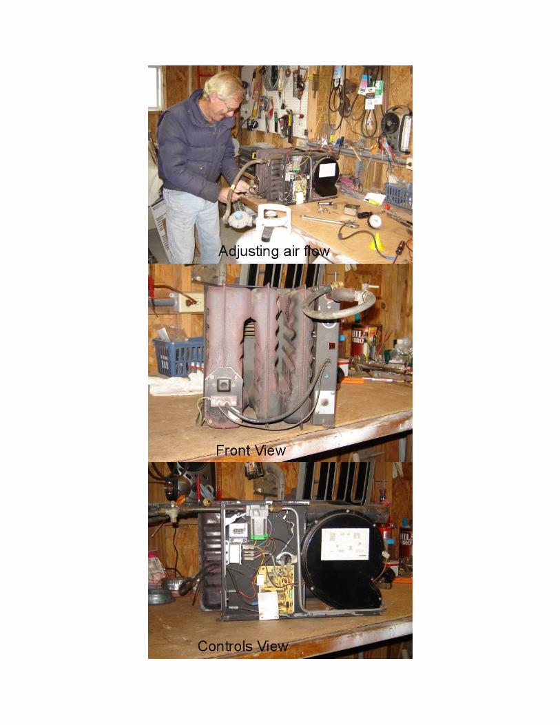
5. Operating Instructions – Burner Adjustment
6. Operating Instructions – Sequence of Normal Operation/Electrical Diagram
7. Component Functions – Fan Switch
8. Component Functions – Limit Switch
9. Component Functions - Microswitch
10. Component Functions – Blower Assembly
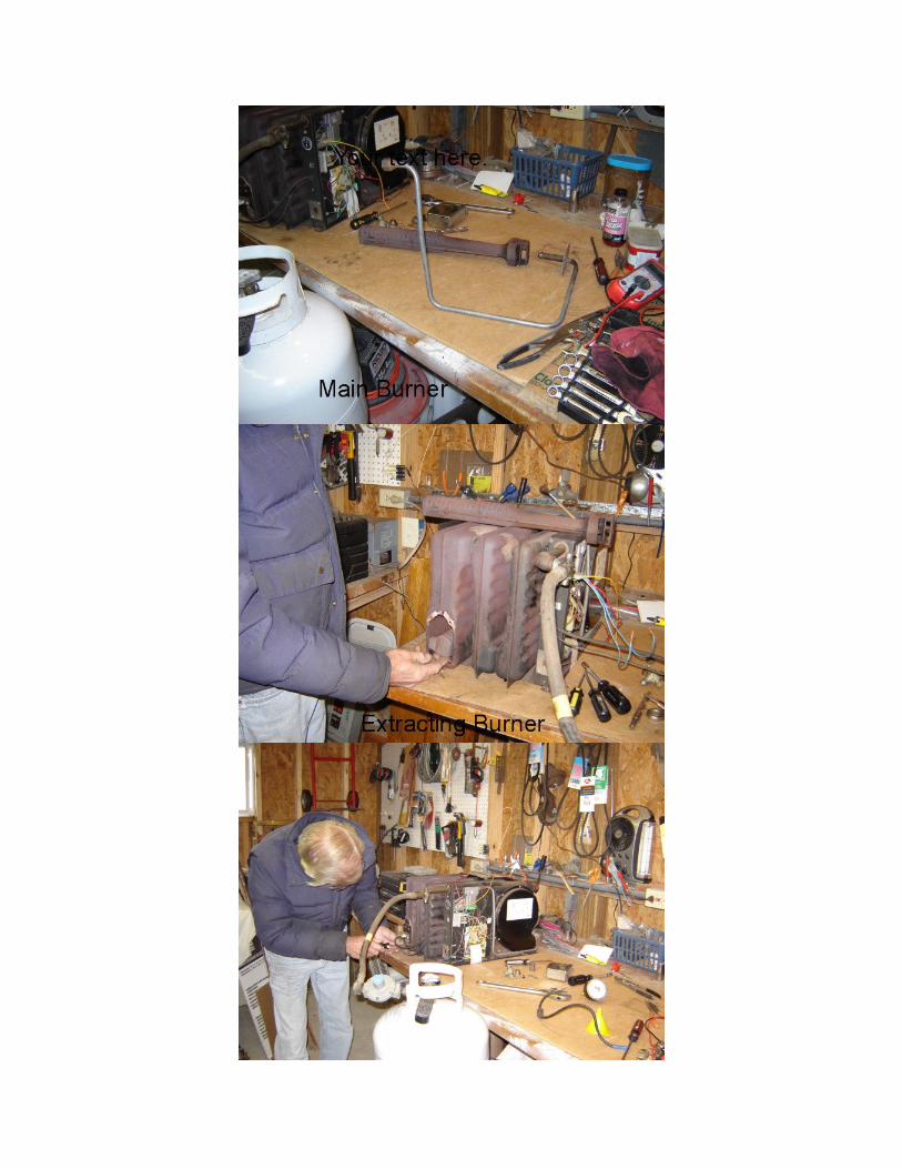
11. Maintenance and Cleaning Instructions
12. Maintenance and Cleaning Instructions – Combustions Chamber Removal
13. Test Setup
14. Hints, Diagnosis, and Corrective Measures Chart
15. Expanded Disassembly
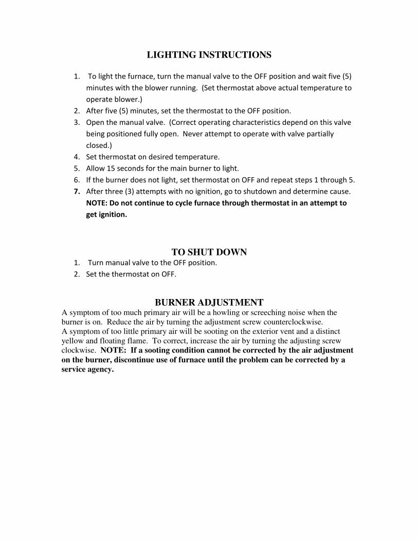
LIGHTING INSTRUCTIONS
1. To light the furnace, turn the manual valve to the OFF position and wait five (5)
minutes with the blower running. (Set thermostat above actual temperature to
operate blower.)
2. After five (5) minutes, set the thermostat to the OFF position.
3. Open the manual valve. (Correct operating characteristics depend on this valve
being positioned fully open. Never attempt to operate with valve partially
closed.)
4. Set thermostat on desired temperature.
5. Allow 15 seconds for the main burner to light.
6. If the burner does not light, set thermostat on OFF and repeat steps 1 through 5.
7. After three (3) attempts with no ignition, go to shutdown and determine cause.
NOTE: Do not continue to cycle furnace through thermostat in an attempt to
get ignition.
TO SHUT DOWN 1. Turn manual valve to the OFF position.
2. Set the thermostat on OFF.
BURNER ADJUSTMENT A symptom of too much primary air will be a howling or screeching noise when the
burner is on. Reduce the air by turning the adjustment screw counterclockwise.
A symptom of too little primary air will be sooting on the exterior vent and a distinct
yellow and floating flame. To correct, increase the air by turning the adjusting screw
clockwise. NOTE: If a sooting condition cannot be corrected by the air adjustment
on the burner, discontinue use of furnace until the problem can be corrected by a
service agency.
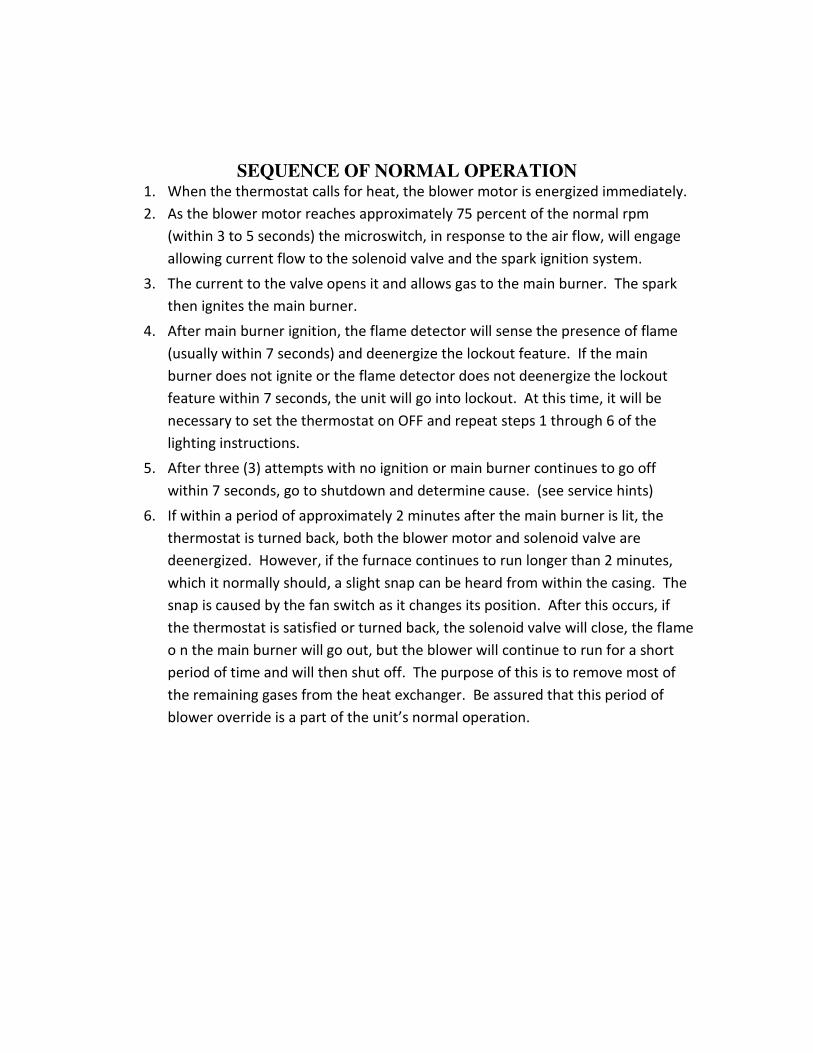
SEQUENCE OF NORMAL OPERATION 1. When the thermostat calls for heat, the blower motor is energized immediately.
2. As the blower motor reaches approximately 75 percent of the normal rpm
(within 3 to 5 seconds) the microswitch, in response to the air flow, will engage
allowing current flow to the solenoid valve and the spark ignition system.
3. The current to the valve opens it and allows gas to the main burner. The spark
then ignites the main burner.
4. After main burner ignition, the flame detector will sense the presence of flame
(usually within 7 seconds) and deenergize the lockout feature. If the main
burner does not ignite or the flame detector does not deenergize the lockout
feature within 7 seconds, the unit will go into lockout. At this time, it will be
necessary to set the thermostat on OFF and repeat steps 1 through 6 of the
lighting instructions.
5. After three (3) attempts with no ignition or main burner continues to go off
within 7 seconds, go to shutdown and determine cause. (see service hints)
6. If within a period of approximately 2 minutes after the main burner is lit, the
thermostat is turned back, both the blower motor and solenoid valve are
deenergized. However, if the furnace continues to run longer than 2 minutes,
which it normally should, a slight snap can be heard from within the casing. The
snap is caused by the fan switch as it changes its position. After this occurs, if
the thermostat is satisfied or turned back, the solenoid valve will close, the flame
o n the main burner will go out, but the blower will continue to run for a short
period of time and will then shut off. The purpose of this is to remove most of
the remaining gases from the heat exchanger. Be assured that this period of
blower override is a part of the unit’s normal operation.
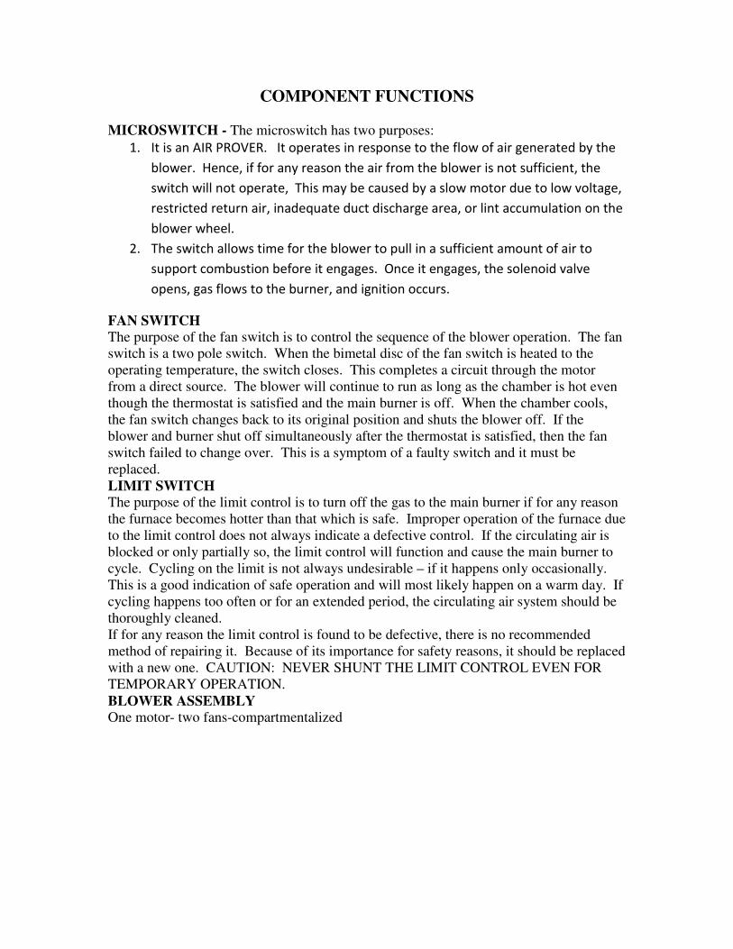
COMPONENT FUNCTIONS
MICROSWITCH - The microswitch has two purposes:
1. It is an AIR PROVER. It operates in response to the flow of air generated by the
blower. Hence, if for any reason the air from the blower is not sufficient, the
switch will not operate, This may be caused by a slow motor due to low voltage,
restricted return air, inadequate duct discharge area, or lint accumulation on the
blower wheel.
2. The switch allows time for the blower to pull in a sufficient amount of air to
support combustion before it engages. Once it engages, the solenoid valve
opens, gas flows to the burner, and ignition occurs.
FAN SWITCH
The purpose of the fan switch is to control the sequence of the blower operation. The fan
switch is a two pole switch. When the bimetal disc of the fan switch is heated to the
operating temperature, the switch closes. This completes a circuit through the motor
from a direct source. The blower will continue to run as long as the chamber is hot even
though the thermostat is satisfied and the main burner is off. When the chamber cools,
the fan switch changes back to its original position and shuts the blower off. If the
blower and burner shut off simultaneously after the thermostat is satisfied, then the fan
switch failed to change over. This is a symptom of a faulty switch and it must be
replaced.
LIMIT SWITCH
The purpose of the limit control is to turn off the gas to the main burner if for any reason
the furnace becomes hotter than that which is safe. Improper operation of the furnace due
to the limit control does not always indicate a defective control. If the circulating air is
blocked or only partially so, the limit control will function and cause the main burner to
cycle. Cycling on the limit is not always undesirable – if it happens only occasionally.
This is a good indication of safe operation and will most likely happen on a warm day. If
cycling happens too often or for an extended period, the circulating air system should be
thoroughly cleaned.
If for any reason the limit control is found to be defective, there is no recommended
method of repairing it. Because of its importance for safety reasons, it should be replaced
with a new one. CAUTION: NEVER SHUNT THE LIMIT CONTROL EVEN FOR
TEMPORARY OPERATION.
BLOWER ASSEMBLY
One motor- two fans-compartmentalized
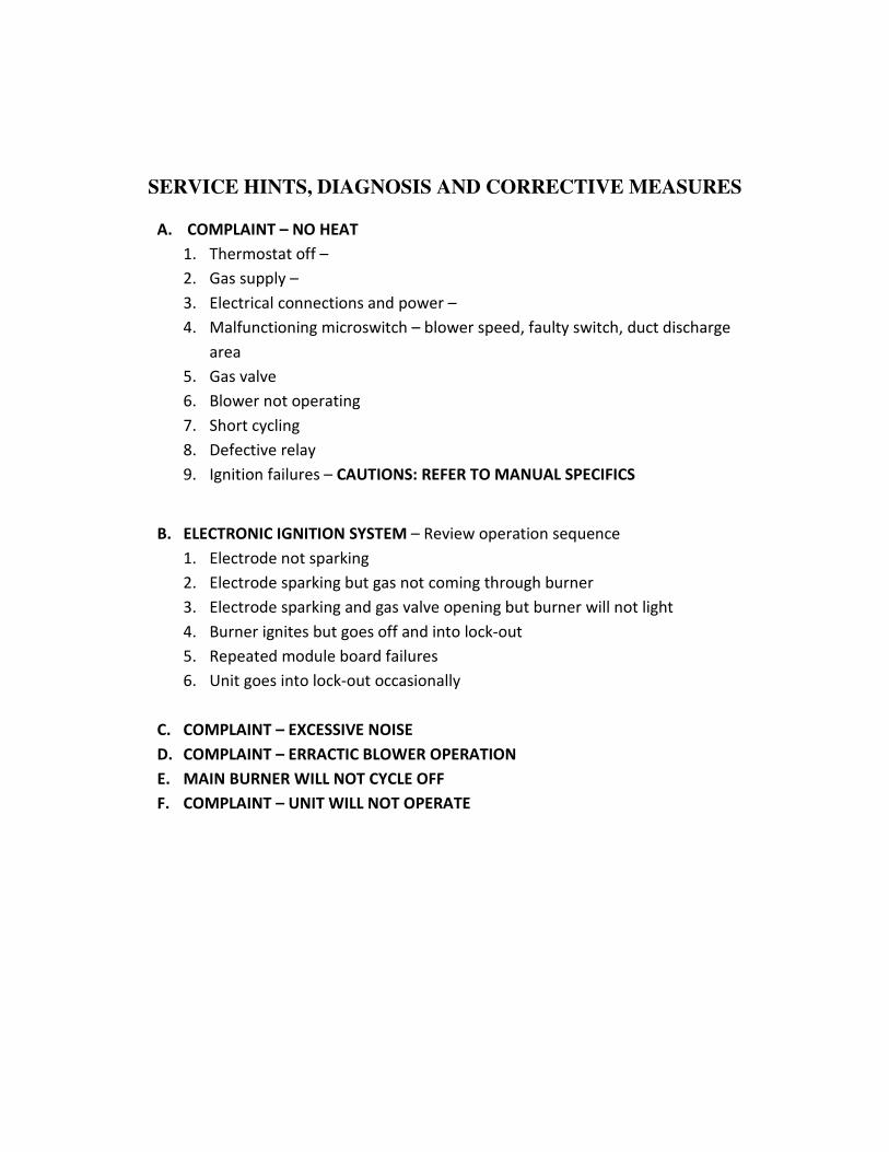
SERVICE HINTS, DIAGNOSIS AND CORRECTIVE MEASURES
A. COMPLAINT – NO HEAT
1. Thermostat off –
2. Gas supply –
3. Electrical connections and power –
4. Malfunctioning microswitch – blower speed, faulty switch, duct discharge
area
5. Gas valve
6. Blower not operating
7. Short cycling
8. Defective relay
9. Ignition failures – CAUTIONS: REFER TO MANUAL SPECIFICS
B. ELECTRONIC IGNITION SYSTEM – Review operation sequence
1. Electrode not sparking
2. Electrode sparking but gas not coming through burner
3. Electrode sparking and gas valve opening but burner will not light
4. Burner ignites but goes off and into lock-out
5. Repeated module board failures
6. Unit goes into lock-out occasionally
C. COMPLAINT – EXCESSIVE NOISE
D. COMPLAINT – ERRACTIC BLOWER OPERATION
E. MAIN BURNER WILL NOT CYCLE OFF
F. COMPLAINT – UNIT WILL NOT OPERATE