successful vision sensing applications in the metal ... vision sensing applications in the metal...
TRANSCRIPT

Dave Fletcher Paper – Session 3: Advances in Smart Cameras & Sensors September 2005
1
Successful Vision Sensing Applications in the Metal Stamping
Industry
Author
David S. Fletcher Area Sales Manager Banner Engineering Minneapolis, Minnesota Abstract
Global market conditions are having an impact on both the supply and demand sides of all businesses. Quality standards continue to rise. Cost pressures continue to be a challenge. Lean processes require you to make the part right, the first time, at the lowest cost and when the customer wants it. Vision sensing is able to address these tough issues and make a difference.
Conference
International Robots & Vision Show Session 3: Advances in Smart Cameras & Sensors September 27-29, 2005 Donald E. Stephens Convention Center Rosemont, Illinois Index Terms Smart vision sensor Metal Stamping Applications with vision sensors Slug-mark detection with vision sensors Vision sensing with 360 o rotation capability Vision sensing with remote-teach capability

Dave Fletcher Paper – Session 3: Advances in Smart Cameras & Sensors September 2005
2
Introduction In this paper we will identify how vision sensing is having an impact on pressroom quality and cost reduction. Vision sensing is a rapidly developing affordable technology that offers the metal stamping industry and other industries global competitiveness. Included in this paper are five example case study applications from the metal stamping industry. Our goal is to help the participant learn how to evaluate and determine the potential of smart vision sensing for their plants and operations. As the trend of globalization continues, many businesses are dealing with economic pressures that are challenging to say the least. The metal stamping industry has seen significant challenges with supply side costs first with steel tariffs and now with a strong Chinese demand for metals. Low cost labor markets are having a significant impact on pricing demands so many metal stamping companies are unable to pass on higher costs. As quality standards have also increased we have moved from 6-sigma to zero-tolerance. Today’s productivity model requires producing quality products the first time with no waste and on a timely basis for the customers’ needs. With the hopes of staying in business, we must achieve this model objective and produce a net profit. Furthermore, next year we must be able to produce the same products at still a lower cost. With the recent advances in smart cameras and vision sensors we have a contributing set of tools to meet these challenges and improve metal stamping productivity. Historical Backdrop The metal forming and metal stamping industry have developed successful models of die-protection and in-die sensing that have been the basis of much of the productivity improvements over the past two-decades. The variety of sensors used to prevent die crashes and downtime have developed from crude wire contact probes to non-contact inductive and photoelectric sensors. Early usage of non-contact sensors relied primarily on the non-contact inductive proximity switch. These robust sensors are well suited for the precision based metal sensing while not being negatively affected by lubricating oils and coolants used in process. Inductive proximity sensors however are limited to very short sensing ranges and small windows of area detection. As needs for sensors with longer detection ranges or having the ability of detection in an area evolved, thus more and more optically based photoelectric sensors were applied. The key to success over the

Dave Fletcher Paper – Session 3: Advances in Smart Cameras & Sensors September 2005
3
Figure 1
past decade has been applying the right technology for the job based on the needs of the process. Optically based photoelectric sensors have become well suited for many of the in-die and on-die applications in today’s modern progressive and transfer presses. Another facet of improving productivity has been to incorporate secondary operations into a die-formed part in the initial process operation. Now by doing in-die tapping, in-die staking, in-die welding etc, we reduce cost by incorporating more value-add to the primary part. As more of these operations are being added, we are adding more quality check sensors to verify these operations. With today’s smart area sensors we can utilize a number of single point sensors or employ an easy to configure smart camera for process verification.
The photoelectric sensor on the left we like to refer to as the rifle and the smart vision sensor on the right we call the smart shotgun. Both have their purpose and place but we are seeing an increase usage in smart shotguns due to the improvements and ease of use just in the past few years.
Smart vision sensors have come down in overall cost dramatically in the past few years such that financial justification is much easier to calculate. Additionally we are rapidly approaching the crossover in the curves that we must apply these products because of competitive cost advantages that they offer.
In 1995 for example, we talked about vision as vision systems and the hardware costs started in the $12,000 - $40,000 cost area. Now in 2005 we talk about vision as smart sensors and the associated hardware costs now start in the $1000 - $2000 area. In 1995 additionally, most systems needed specialty programming skill sets that required the services of a highly trained systems integrator. User plant support training could require an additional one to two weeks. Now in 2005, the usage
Figure 2

Dave Fletcher Paper – Session 3: Advances in Smart Cameras & Sensors September 2005
4
Figure 3
of these newer products is equivalent to the skill sets of a sensor specialist and training is a matter of days. User plant support training can be now also a matter of hours. Applications
In the picture of Figure 3, we have a Pro camera inspecting a reel-to-reel strip to insure the quality of the formed part retained in the carrier strip. In this application the smart vision sensor is mounted 4-inches above the material. A fixture was built by the customer to allow the vision sensor to look at each part as a silhouette to inspect for part quality. A pair of individual plastic fiber optic cables is used to trigger
the vision sensor on each pilot hole on the strip. The backlighting technique used in this application provides an outstanding object contrast to provide quick and efficient part inspection on a real time basis as the press is running.
In the screen image captured from the setup computer, an inspection of each of the formed legs is being provided by the Pro vision sensor. Locate tools have been used to allow for movement within the fixture and still provide for accurate measurement of the part. In this application the customer is measuring both the dimensions of each of the four lead frame spades,
Figure 4

Dave Fletcher Paper – Session 3: Advances in Smart Cameras & Sensors September 2005
5
plus the spacing in between. In this specific frame, the inspection has passed as noted by the Green P box in the Run window software display. With these newer smart sensors today, easy to use intuitive software is used to develop either a single or series of part inspection programs. These multiple part inspection programs are then stored in the smart sensors memory and the computer disconnected. A live video feed resident on these sensors allow for a real time display to be displayed on a line mounted monitor. In this next metal stamping part inspection example, we are looking at 8 different aspects of a reel-to-reel stamped brass part that will be part of an over molded contact assembly. With today’s smart vision sensors, creating intricate inspection programs like this are easy to create and modify. The software used with this product is intuitive and easy to learn. In this application example, each blue block below represents a tool created on a reference image of the part we want to inspect. In a straight forward and easy to follow fashion, a tool is selected by selecting the tool with a mouse click and drawing a line, box, circle or other geometric object on the image. Since parts or in this case the strip may move slightly in the inspection fixture, a locate tool is first applied to find the
Figure 5

Dave Fletcher Paper – Session 3: Advances in Smart Cameras & Sensors September 2005
6
exact part location so that exact fixturing may not be necessary. In this case we are using 7 object tools to verify the presence and correct size and location of the frame support for these delicate parts. We have also applied a couple of edge tools to measure the distance from the large contact pad area to the end of the terminal eyelet. After drawing or laying down these smart vision sensor tools on the reference image, we then create test tools that allow us to apply the level of tolerances needed to assure high quality parts for the customer. The time needed to create this inspection program, took less than 5 minutes. The training needed to be able duplicate this for a non-vision expert would be a couple of hours. As today’s products are becoming both more affordable and easy to use, the return on investment to utilize smart vision sensors provides a very quick payback.
Figure 6

Dave Fletcher Paper – Session 3: Advances in Smart Cameras & Sensors September 2005
7
In Figure 6 we have zoomed in on the length measurement that we have applied to this part to make sure the terminal eyelet lead is not deformed or damaged. Again the point I wish to emphasize is that doing these types of intricate inspections can be very easy to learn and apply for production support workers.
Here is an example of an expanded inspection results window from this application. All of the inspections and tests have passed as verified by the Green Check marks for each tool. The total inspection time for this application is less than 55 ms which allows the press to run at maximum speed. The press speed for this part is around 350 Strokes per Minute and this inspection can keep up with press speeds in excess of 1000 Strokes per Minute. You will also note that a processing time is listed for each specific inspection tool in Figure 7. Today’s smart vision sensors are also very fast so that they can keep up with high speed inspection applications. In some cases it may be necessary to apply more than one vision sensor to the inspection process. With affordability
well below levels of just a few years ago, this does not become cost prohibitive and allows for greater usage flexibility. In the first two application examples we featured vision sensor applications with a lighting technique known as back lighting. This method is one of a number of different lighting techniques that can be successfully applied to part inspection with vision sensors.
Figure 7
Figure 8

Dave Fletcher Paper – Session 3: Advances in Smart Cameras & Sensors September 2005
8
Lighting has always been a critical factor to successful utilization of vision sensors. In very simple terms the goal of lighting is to be able to highlight the difference between good and bad product. As we use our eyes with various lighting or reflection techniques to inspect objects, today’s vision sensors apply many of the same principals. In this next application example we will feature another special lighting technique for an exciting area of quality improvement for the metal stamping industry. In metal stamping processes, pulling slugs has been an ongoing quality issue since the first progressive die set was built. Historically, parts and strips would have to be carefully inspected manually to look for surface cuts and slug marks.
In the image shown in Figure 9, we have again a reel-to-reel strip that has a number of damaged pieces due to pulled slugs marring the surface finish. In the highlighted Blob_2 red box, the
small red plus signs show where two slug marks are present on the right side of this strip. By applying low-angle of incidence LED lighting to this strip, we can create any portion of the strip that has verticality as a hot spot or white pixel. In this specific strip, the circular bull’s-eye is a drawn cup dome with the center dark area an actual electrical contact surface. Since we know that this area has some vertical proportion, we have masked off this area as noted by the light blue circle covering this area of the region of interest. The low-angle of incidence lighting causes slug marks as seen on this strip to bloom as seen by the bright white blob of pixels in an unwanted area. A Blob Tool is a very common vision sensor acronym tool that represents binary large object. It is one of a number of widely used vision sensor tools that is making a difference to improved production quality and reduction of waste.
Figure 9

Dave Fletcher Paper – Session 3: Advances in Smart Cameras & Sensors September 2005
9
In the metal stamping application examples covered previously, these entire smart vision sensor installations have the sensor located outside of the press. In Figure 10, we have an example of a portable smart sensor self-contained
inspection system that can be placed between the press and the take-up reel. In this specific application, courtesy of Wiegel Tool Works of Wood Dale, Illinois, they are inspecting a critical electrical contact spade for deformed legs. When this specific job is running in the press, the smart vision sensor cart is rolled into place and the ability to insure that each part is to specification is assured. When out of tolerance parts are detected, the press is stopped and the deformed parts
sectioned out of the strip, spliced and production is back on line in a matter of minutes. Without some form of vision monitoring and documentation they
were continuously dealing with returned reels requiring re-inspection and manual handling that was very expensive. In Figure 11 we have an example of a deformed portion of the strip that this vision sensor is able to readily detect and
Figure 10
Figure 11
Dave Fletcher Paper – Session 3: Advances in Smart Cameras & Sensors September 2005
10
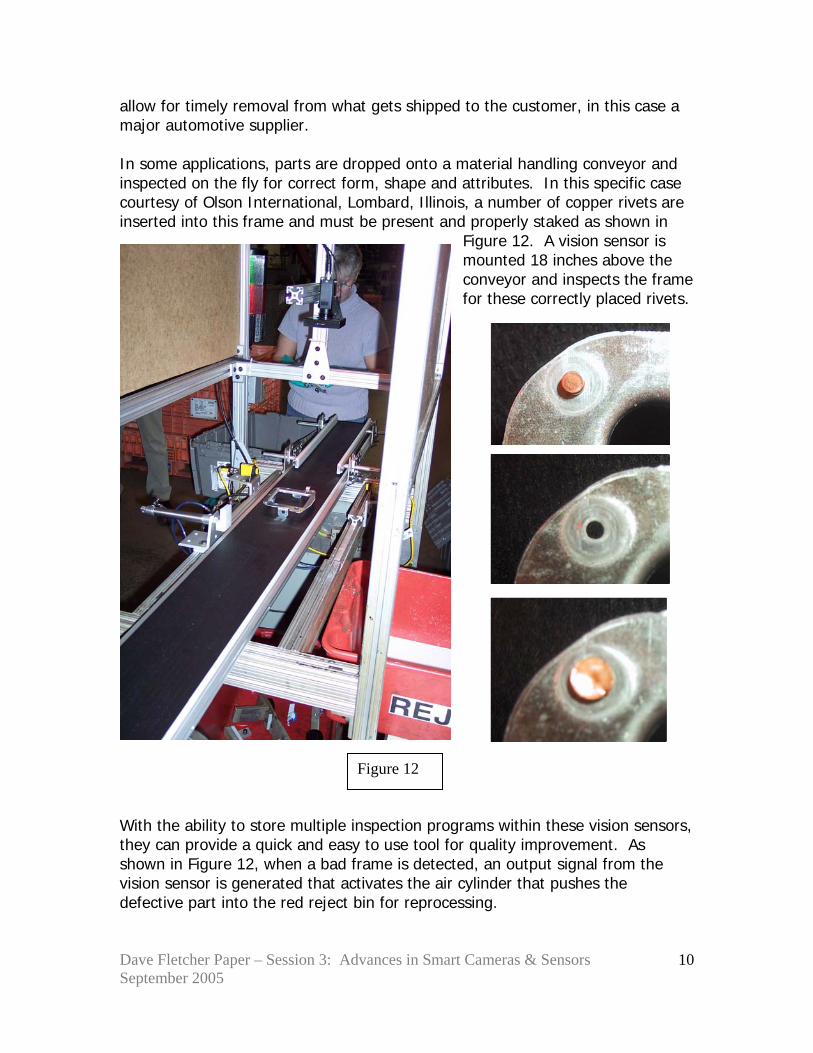
allow for timely removal from what gets shipped to the customer, in this case a major automotive supplier. In some applications, parts are dropped onto a material handling conveyor and inspected on the fly for correct form, shape and attributes. In this specific case courtesy of Olson International, Lombard, Illinois, a number of copper rivets are inserted into this frame and must be present and properly staked as shown in
Figure 12. A vision sensor is mounted 18 inches above the conveyor and inspects the frame for these correctly placed rivets.
With the ability to store multiple inspection programs within these vision sensors, they can provide a quick and easy to use tool for quality improvement. As shown in Figure 12, when a bad frame is detected, an output signal from the vision sensor is generated that activates the air cylinder that pushes the defective part into the red reject bin for reprocessing.
Figure 12

Dave Fletcher Paper – Session 3: Advances in Smart Cameras & Sensors September 2005
11
The development of this technology continues to rapidly expand as smart vision sensors are becoming smarter and faster. In these last application examples, we have selected to feature two widely expanded capabilities of vision sensors. One critical factor of some applications is random orientation. Some of today’s products being offered have a full 360 degree recognition and capability. When products are able to be inspected no matter what the orientation, this simplifies the usage of vision sensors tremendously.
In the example shown in Figure 13, assembly screws are traveling on a conveyor and can be in any orientation. The ability to inspect these parts no matter what orientation dramatically reduces the cost of utilization with this technology.
Another key development has been the ability to utilize a remote-teach ability of smart vision sensors. Now when a product is changed, in lieu of pulling out a computer to make an inspection program change, simply activate a remote teach function at the machine and begin the new inspection. This may not be for every inspection application but it
does offer some new capabilities that recently were simply not available. In the metal stamping and metal forming industry we have seen quite a number of applications that have helped suppliers retain customers by applying vision sensors as a corrective action to a quality problem. Often times we have seen the payback calculations produce a return on investment in simply a matter of a few weeks. Most important in virtually every customer survey has been the ease
Figure 13
Figure 14

Dave Fletcher Paper – Session 3: Advances in Smart Cameras & Sensors September 2005
12
of use and this will continue to become more important as plants and factories are running leaner and leaner. If there are any questions regarding the material in this paper, Dave Fletcher can be reached at Banner Engineering Corporation, Minneapolis, Minnesota. Email address: [email protected] Please include your return email address or telephone number for follow up contact and rely.
Index of Figures:
Fig. 1: Single-point sensor versus Area-based sensor Fig. 2: Cost utilization versus increasing standards curve Fig. 3: Picture of Pro camera inspecting metal strip Fig. 4: Computer monitor image of inspection software running the inspection from Fig. 3 Fig. 5: Program example of detail inspection on electrical contact for all frame carrier legs and properly shaped terminal eyelet Fig. 6: Expanded screen highlighting Measure Tool being applied in a critical dimensional requirement Fig. 7: Expanded results screen window illustrating what today’s vision sensor software can offer in inspection details Fig. 8: Matrix overview of lighting technique options Fig. 9: Metal forming strip with slug marks being detected by vision sensor Fig. 10: Photograph of vision sensor cart located between stamping press and take-up reeler Fig. 11: Photograph of damaged parts from application featured in Fig. 10 Fig. 12: Photograph of conveyor handling and vision sensor inspection for missing or deformed rivets on automotive part Fig. 13: Illustration featuring 360 degree orientation capability Fig. 14: Illustration featuring Remote-Teach capability