suggested analysis and design procedures for combined ... suggested analysis... · tion phenomenon...
TRANSCRIPT
ACI 336.2~~88(Reapproved 1993)
This document has been approved for use by agen-cies of the Department of Defense and for listing inthe DOD Index of Specifications and Standards.
Suggested Analysis and Design Procedures forCombined Footings and Mats
Reported by ACI Committee 336
Edward J. Ulrich Shyam N. Shukla
Chairman Secretary
Clyde N. Baker, Jr.Steven C. BallJoseph E. Bowles
Joseph P. ColacoM. T. Davisson
John A. Focht. Jr.M . Gaynor -John P. GnaedingerFritz Kramrisch
Hugh S. LacyJim LewisJames S. Notch
Ingvar Schousboe
John F. SeidenstickerBruce A. SuprenantJagdish S. SyalJohn J. Zils
This report deals with rhe design of foundations carrying more [hana single column of wall load. These foundarions are called combinedfootings and mats. Although it is primarily concerned with rhe slruc-rural aspecrs of the design, considerations of soil mechanics canno,be eliminated and rhe designer should focus on the important inrer-relalion of the Iwo fields in connection with the design of such srruc-rural elements. This report is limited 10 vertical effecrs of all loadingconditions. The report excludes slabs on grade.
Chapter 4-Combined footings, p. 336.2R74. I-Rectangular-shaped footings4.2-Trapezoidal or irregularly shapPd footings4.3-Overturning calculations
Keywords: ~~ncreles; earth pressure; footings; foundations; loads (forces): mat
loundntions; reinforced concrete: soil mechanics; strews; structural analysis;struclural design.
Chapter 5-Grid foundations and strip footingssupporting more than two columns, p. 336.2R-8
5.1 -General5.2-Footings supporting rigid structures5.3-Column spacing
CONTENTSChapter 1 -General, p. 336.2R.2
5.4-Design procedure for flexible footings5.5-Simplified procedure for flexible footings
1. l-NotationI .2-ScopeI .3-Definitions and loadingsI .4-Loading combinationsI .5-Allowable pressure
1.6-Time-dependent considerat ions
Chapter 6-Mat foundations, p. 336.2R-9
I1.7-Design overview
Chapter P-Soil structure interaction, p. 336.2R.42. I-General2.2-Factors to be considered2.3-Investigation required to evaluate variable factors
Chapter 3-Distribution of soil reactions,p. 336.2R6
3.1 -General
3.2-Straight-line distribution3.3-Distribution of soil pressure governed by modulus of subgrade
reaction
6. I-General6.2-Finite difference method6.3-Finite grid method
6.4-Finite element method6.5-Column loads6.6-Symmetry6.7-Node coupling of soil effects
6.8-Consolidation settlement6.9-Edge springs for mats6. IO-Computer output6. I l-Two-dimensional or three-dimensional analysis6. I2-Mat thickness
6.13-Parametric studies6.14-Mat foundation detailing/construction
Chapter 7-Summary, p. 336.2R.20
ACI Committee Reports, Guides, Standard Practices, and Commentariesare intended for guidance in planning, designing, executing, and inspectingconstruct ion. This document is intended for the use of individuals whoare competent to evaluate the signif icance and l imitations of i ts con-tent and recommendations and who wil l accept responsibil i ty for theapplication of the material i t contains. The American Concrete Institutedisclaims any and all responsibi l i ty for the stated principles. The Insti tuteshall not be liable for any loss or damage arising therefrom.
Reference to this document shall not be made in contract documents. Ifitems found in this document are desired by the Architect/Engineer to bea part of the contract documents, they shall be restated in mandatory lan-guage for incorporation by the Architect/Engineer.
This report supersedes AC1 336.2R-66 (Reapproved 1980).Copyright 0 1993. American Concrete Institute.All rights reserved including rights of reproduction and use m any form or by any
means. including the making of copies by any photo process, or by electronic ormechanical device, printed, wntten. or oral. or recording for sound or visual reproduc-tion or for use in any knowledge or retrieval system or device, unless permIssion inwriting is obtained from the copyright proprietors
336.2k1
226.2R.2 MANUAL OF CONCRETE PRACTICE
Chapter 8--References, p. 338.2R-218.1-Specified and/or recommended references
8.2-Cited references
CHAPTER l-GENERAL1.1 -Notation
The following dimensioning notation is used: F =force; I = length; Q = dimensionless.
A =b =
B =B, =B, =
C =
D =
Q. =D, =
D, =
e =
e, =
E =
E. =E’ =
E. =
F,:, =
G =
h. =H =
H,. =A H =I =
I” =I, =I. =
=; =k, =k. =
k: =
k. =
k., =
K =
K, =L =
L. =
L., =
M’ =
M, =
base area of footing, I:width of pressed edge, Pfoundation width, or width of beam column element. I’mat width. P
plate width. Pdistance from resultant of vertical forces 10 overturning edgeof the base, Pdead load or related internal moments and forces, F
dead load for overturning calculations, Fthe depth D, should bc the depth of soil measured adjacent10 the pressed edge of the combined fooling or mat at thetime the loads being considered are applied
stage dead load consisting of the unfactored dead load of thestructure and foundation at a particular time or stage ofconstruction. Feccentricity of resultant of all vertical forces, Peccentricity of resultant of all vertical forces with respect to
the x- and y-axes (e. and e., respectively), Pvertical effects of earthquake simulating forces or related in-ternal moment or force, F
modulus of elasticity of concrete, F/P‘modulus of elasticity of the materials used in the superstruc-
ture, F/‘/I:soil modulus of elasticity. F/P:vertical effects of lateral loads such as earth pressure, water
pressure, fill pressure, surcharge pressure, or similar lateralloads, F
shear modulus of concrete, F/P’height of any shearwalls in struc1ure. Psettlement of foundation or point. I’consolidation (or recompression) settlement of point i, I’
magnitude of computed foundation settlement. Pplan moment of inertia of footing (or mat) abour any axis
x(0 or YU.). P’
moment of inertia of one unit width of the superstructure. I”moment of inertia per one unit width of the foundation, P’base shape factor depending on foundation shape and flexi-bility, P’vertical displacement of a node, I’torsion constant for finite grid elements, I”
coefficient of subgrade reaction from a plate load test, F/I+‘coefficient of subgride reaction cemribution 10 node i. F/I”revised coefficient of subgrade reaction contriburion to nodei, F/P’, see Section 6.8q/6 = coefficient (or modul.us) of vertical subgrade reac-
tion; generic term dependent on dimensions of loaded area,F/P’basic value of coefficient of vertical subgrade reaction for a
square area with width B = I Cr. F/‘/I”spring constant computed as contributory node area Y k,, F/Irelative stiffness factor for foundation. Qlive load or related internal moments and forces produced bythe load, F
sustained live loads used IO estimate settlemem, f‘. A lypicalvalue would be 50 percent of all live loads.stage service live load consisting of the sum of all unfac-
tored live loads at a particular stage of construction, Fbending moment per unit length, F I’overturning moment about base of foundation caused by anearthquake simulating force. F I’
M, =
hf. =
M. =
M” =
II =
P =
4 =
Q. =4. =
Q.r =
4. =
A, =
R, =
R I _I” =
S =
SR =
1. =w =
x, =
2 =Z’ =
c5 ==
h” =
b =
V =
z =
Y =
overturning moment about base of foundation. caused by F,:.loads, F Poverturning moment about base of foundation. caused bywind loads, blast. or similar lateral loads, F f
largest overturning moment about the pressed edge or cen-troid of the base, F Presultant resisting moment. F Pexponent used 10 relate plate k,. 10 mat k.. Q
any force acting perpendicular 10 base area, Fsoil contact pressure compukd or actual, F/I’!allowable soil contact pressure, F /F :unconfined (undrained) compression strength of a cohesivesoil, F/P:ultimate soil bearing capacity; a computed value (0 allow
computation of ultimate stregth design moments and shearsfor the foundation design, also used in overturning calcula-tions, F/P:actual or computed soil contact pressure ac a node point asfurnished by the mat analysis. The contact pressures are
evaluated by the gcotechnical analysis for compatibility wirhq, and foundation movement, F/F:average increase in soil pressure due to unit surface contactpressure, F/‘/F’
resultant of all given design loads acting perpendicular IO
base area, Fleast resultant of all forces acting perpendicular to base areaunder any condition of loading simultaneous with the over-
turning moment. Fsection modulus of mat plan area abour a specified axis; S.about x-axis; S, about y-axis, I”
stability ratio (formerly safety factor). Qthickness of shearwalls. Ivertical effects of wind loads, blast. or similar lateral loads,F
the maximum deflection of the spring al node i as a linearmodel, Pfoundation base length or length of beam column clement, Pfooling effective length measured from the pressed edge IO
the posi t ion al which the contact pressure is zero, I ’
vertical soil displacement, Ptorsion constant adjustment factor, Qfooting stiffness evaluation factor defined by Eq. (S-3). l/PPoisson’s ratio, Q
distance from the pressed edge 10 R. 1,1 (see Fig. 4-l and 4-2.Psummation symbol, Qunit weight of soil, F/P’
1 .P-ScopeThis report addresses the design of shallow founda-
tions carrying more than a single column or wall load.Although the report focuses on the structural aspects ofthe design, soil mechanics considerations are vital andthe designer should include the soil-structure interac-tion phenomenon in connection with the design ofcombined footings and mats. The report excludes slabs-on-grade.
1.3-Definitions and loadingsSoil contact pressures acting on a combined footing
or mat and the internal stresses produced by themshould be determined from one of the load combina-tions given in Section 1.3.2, whichever produces themaximum value for the element under investigation.Critical maximum moment and shear may not neces-sarily occur with the largest simultaneously applied loadat each column.

ANALYSIS AND DESIGN OF COMBINED FOOTINGS AND MATS 336.2R-3
1.3. I DefinitionsCoefficient of vertical subgrade reaction &,--Ratio be-
tween the vertical pressure against the footing or matand the deflection at a point of the surface of con-tact
k, = q/6
Combined footing-A structural unit or assembly ofunits supporting more than one column load.
Contact pressure q-Pressure acting at and perpendic-ular to the contact area between footing and soil,produced by the weight of the footing and all forcesacting on it.
Continuous footing-A combined footing of prismaticor truncated shape, supporting two or more columnsin a row.
Grid foundation-A combined footing, formed by in-tersecting continuous footings, loaded at the inter-section points and covering much of the total areawithin the outer limits of assembly.
Mat foundation-A continuous footing supporting anarray of columns in several rows in each direction,
having a slablike shape with or without depressionsor openings, covering an area of at least 75 percentof the toal area within the outer limits of the assem-bly.
Mat area-Contact area between mat foundation andsupporting soil.
Mat weight-Weight of mat foundation.Modulus of subgrade reaction-See coefficient of ver-
tical subgrade reaction.Overburden-Weight of soiI or backfill from base of
foundation to ground surface. Overburden should bedetermined by the geotechnical engineer.
Overturning-The horizontal resultant of any combi-nation of forces acting on the structure tending torotate the structure as a whole about a horizontalaxis.
Pressed edge-Edge of footing or mat along which thegreatest soil pressure occurs under the condition ofoverturning.
Soil stress-strain modulus-Modulus of elasticity of soiland may be approximately related (Bowles 1982) tothe coefficient of subgrade reaction by the equation
E, = k&I - $)I,,
Soil pressure-See contact pressure.Spring constant-Soil resistance in load per unit de-
flection obtained as the product of the contributoryarea and k,. See coefficient of vertical subgrade re-action.
Stability ratio (SRI-Formally known as safety factor,it is the ratio of the resisting moment M, to the over-turning moment M,,.
Strip footing: See continuous footing definition.Subgrade reaction: See contact pressure and Chapter 3.Surcharge: Load applied to ground surface above the
foundation.
1.3.2 Loadings-Loadings used for design shouldconform to the considerations and factors in Chapter 9of AC1 318 unless more severe loading conditions arerequired by the governing code, agency, structure, orconditions.
1.3.2.1 Dead loads-Dead load D consisting of thesum of:
a. Weight of superstructure.b. Weight of foundation.c. Weight of surcharge.d. Weight of fill occupying a known volume.
1.3.2.2 Live loads-Live load L consisting of thesum of:
a. Stationary or moving loads, taking into accountallowable reductions for multistory buildings or largefloor areas, as stated by the applicable building code.
b. Static equivalents of occasional impacts.Repetitive impacts at regular intervals, such as those
caused by drop hammers or similar machines, and vi-bratory excitations, are not covered by these designrecommendations and require special treatment.
1.3.2.3 Effects of lateral loads-Vertical effects oflateral loads FVh such as:
a. Earth pressure.b. Water pressure.c. Fill pressure, surcharge pressure, or similar.d. Differential temperature, differential creep and
shrinkage in concrete structures, and differential settle-ment .
Vertical effects of wind loads, blast, or similar lat-eral loads W.
Vertical effects of earthquake simulating forces E.Overturning moment about base of foundation,
caused by earthquake simulating forces MC.Overturning moment about base of foundation,
caused by F,,, loads MF.Overturning moment about foundation base, caused
by wind loads, blast, or similar lateral loads M,.Dead load for overturning calculations D,,, consist-
ing of the dead load of the structure and foundationbut including any buoyancy effects caused by partspresently submerged or parts that may become sub-merged in the future. The influence of unsymmetricalfill loads on the overturning moments M,,, as well as theresultant of all vertical forces R, ,,,,“, shall be investi-gated and used if found to have a reducing effect on thestability ratio SR.
Service live load L,, consisting of the sum of all un-factored live loads, reasonably reduced and averagedover area and time to provide a useful magnitude forthe evaluation of service settlements. Also called SUS-
rained live load.Stage dead load D,,, consisting of the unfactored
Dead Load of the structure and foundation at a partic-ular time or stage of construction.
Stage service live load L,,, consisting of the sum of allunfactored Live Loads up to a particular time or stageof construction, reasonably reduced and averaged overarea and time, to provide a useful magnitude for theevaluation of settlements at a certain stage.

336.2R-4 MANUAL OF CONCRETE PRACTICE
1.4-Loading combinationsIn the absence of conflicting code requirements, the
following conditions shou!d be analyzed in the designof combined footings and mats.
1.4.1 Evaluarion of soil pressure-Select the combi-nations of unfactored (service) loads which will pro-duce the greatest contact pressure on a base area ofgiven shape and size. The allowable soil pressure shouldbe determined by a geotechnical engineer based on ageotechnical investigation.
Loads should be of Types D, L, F ,,,, I+‘, and E as de-scribed in Section 1.3.2, and should include the verticaleffects of moments caused by horizontal components ofthese forces and by eccentrically (eccentric with regardto the centroid of the area) applied vertical loads.
a. Consider buoyancy of submerged parts where thisreduces the stability ratio or increases the contact pres-sures, as in flood conditions.
b. Obtain earthquake forces using the applicablebuilding code, and rational analysis.
1.4.2 Foundation strength design-Although the al-lowable stress design according to the Alternate DesignMethod (ADM) is considered acceptable, it is best todesign footings or mat foundations based on theStrength Design Method of AC1 318. Loading condi-tions applicable to the design of mat foundations aregiven in more detail in Chapter 6.
After the evaluation of soil pressures and settlement,apply the load factors in accordance with Section 9.2 ofAC1 318.
1.4.3 Overturning-Select from the several applica-ble loading combinations the largest overturning mo-ment M,, as the sum of all simultaneously applicableunfactored (service) load moments (M,, MM, and M,)and the least unfactored resistance moment M, result-ing from D,, and F,,, to determine the stability ratio SRagainst overturning in accordance with the provisionsof Chapter 4.
1.4.4 Settlement-Select from the combinations ofunfactored (service) loads, the combination which willproduce the greatest settlement or deformation of thefoundation, occurring either during and immediatelyafter the load application or at a later date, dependingon the type of subsoil. Loadings at various stages ofconstruction such as D. D,,, and L,, should be evalu-ated to determine the initial settlement, long-term set-tlement due to consolidation, and differential settle-ment of the foundation.
1.5-Allowable pressureThe maximum unfactored design contact pressures
should not exceed the allowable soil pressure, 4,. Q,should be determined by a geotechnical engineer.Where wind or earthquake forces form a part of theload combination, the allowable soil pressure may beincreased as allowed by the local code and in consulta-tion with the geotechnical engineer.
1.6-Time-dependent considerationsCombined footings and mats are sensitive to time-
dependent subsurface response. Time-dependent con-
siderations include (1) stage loading where the initialload consists principally of dead load; (2) foundationsettlement with small time dependency such as mats onsand and soft carbonate rock; (3) foundation settle-ment which is time-dependent (usually termed consoli-dation settlements) where the foundation is sited overfine-grained soils of low permeability such as silt andclay or silt-clay mixtures; (4) variations in live loading;and (5) soil shear displacements. These five factors mayproduce time dependent changes in the shears and mo-ments.
1.7-Design overviewMany structural engineers analyze and design mat
foundations by computer using the finite elementmethod. Soil response can be estimated by modelingwith coupled or uncoupled “soil springs.” The springproperties are usually calculated using a modulus ofsubgrade reaction, adjusted for footing size, tributaryarea to the node, effective depth, and change of mod-ulus with depth. The use of uncoupled springs in themodel is a simplified approximation. Section 6.7 con-siders a simple procedure to couple springs within theaccuracy of the determination of subgrade response.The time-dependent characteristics of the soil response,consolidation settlement or partial-consolidation settle-ment, often can significantly influence the subgrade re-action values. Thus, the use of a single constant mod-ulus of subgrade reaction can lead to misleading re-sults.
Ball and Notch (1984). Focht et al. (1978), and Ban-avalkar and Ulrich (1984) address the design of matfoundations using the finite element method and time-dependent subgrade response. A simplified method,using tables and diagrams to calculate moments, shears,and deflections in a mat may be found in Bowles(1982), Hetenyi (1946), and Shukla (1984). .
Caution should be exercised when using finite ele-ment analysis for soils. Without good empirical results,soil springs derived from values of subgrade reactionmay only be a rough approximation of the actual re-sponse of soils. Some designers perform several finiteelement analyses with soil springs calculated from arange of subgrade moduli to obtain an adequate de-sign.
CHAPTER 2-SOIL STRUCTURE INTERACTION2.1 -General
Foundations receive loads from the superstructurethrough columns, walls, or both and act to transmitthese loads into the soil. The response of a footing is acomplex interaction of the footing itself, the super-structure above, and the soil. That interaction maycontinue for a long time until final equilibrium is es-tablished between the superimposed loads and the sup-porting soil reactions. Moments, shears, and deflec-tions can only be computed if these soil reactions canbe determined.
ANALYSIS AND DESIGN OF COMBINED FOOTINGS AND MATS 336.2R.5
2.2-Factors to be consideredNo analytical method has been devised that can eval-
uate all of the various factors involved in the problemof soil-structure interaction and allow the accurate de-termination of the contact pressures and associatedsubgrade response. Simplifying assumptions must bemade for the design of combined footings or mats. Thevalidity of such simplifying assumptions and the accu-racy of any resulting computations must be evaluatedon the basis of the following variables.
2.2.1 Soil type below the footing-Any method ofanalyzing a combined footing should be based on a de-termination of the physical characteristics of the soillocated below the footing. If such information is notavailable at the time the design is prepared, assump-tions must be made and checked before construction todetermine their validity. Consideration must be given tothe increased unit pressures developed along the edgesof rigid footings on nongranular soils and the oppositeeffect for footings on granular soils. The effect ofembedment of the footing on pressure variation mustalso be considered.
2.2.2 Soil type at greater depths-Consideration oflong-term consolidation of deep soil layers should beincluded in the analysis of combined footings and mats.Since soil consolidation may not be complete for anumber of years, it is necessary to evaluate the behav-ior of the foundations immediately after the structureis built, and then calculate and superimpose stressescaused by consolidation.
2.2.3 Size of footing-The effect of the size of thefooting on the magnitude and distribution of the con-tact pressure will vary with the type of soil. This factoris important where the ratio of perimeter to area of afooting affects the magnitude of contact pressures, suchas in the case of the increased edge pressure, Section2.2.1, and the long-term deformation under load, Sec-tion 2.2.2. The size of the footing must also be consid-ered in the determination of the subgrade modulus. SeeSection 3.3.
2.2.4 Shape of fooling--This factor also affects theperimeter-to-area ratio. Generally, simple geometricforms of squares and rectangles are used. Other shapessuch as trapezoids, octagons, and circles are employedto respond to constraints dictated by the superstructureand property lines.
2.2.5 Eccenrricity of loading-Analysis should in-clude consideration of the variation of contact pres-sures from eccentric loading conditions.
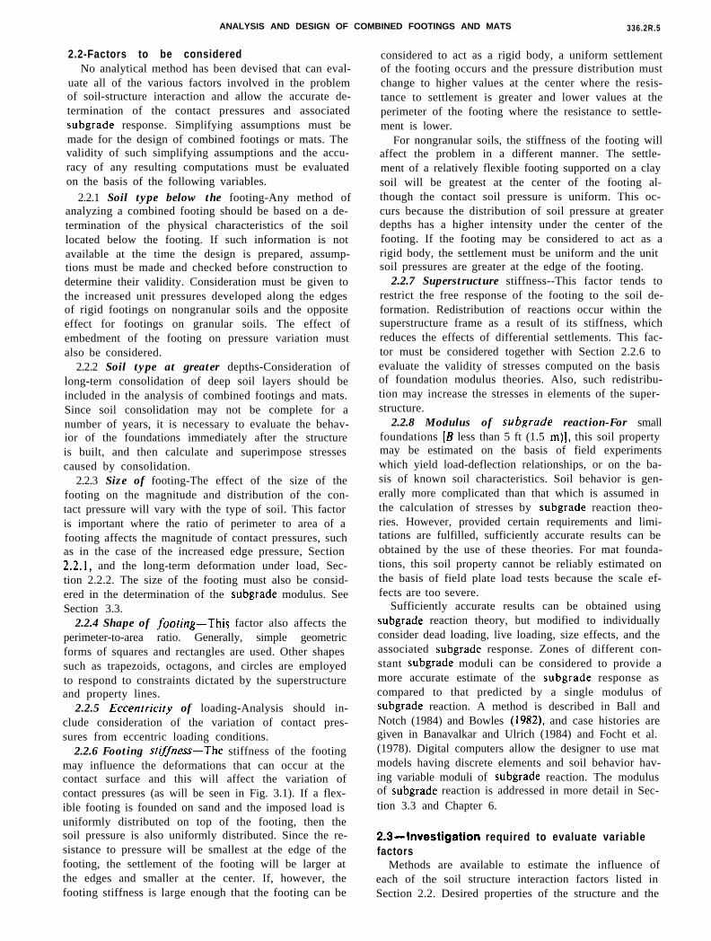
2.2.6 Footing sriffness-The stiffness of the footingmay influence the deformations that can occur at thecontact surface and this will affect the variation ofcontact pressures (as will be seen in Fig. 3.1). If a flex-ible footing is founded on sand and the imposed load isuniformly distributed on top of the footing, then thesoil pressure is also uniformly distributed. Since the re-sistance to pressure will be smallest at the edge of thefooting, the settlement of the footing will be larger atthe edges and smaller at the center. If, however, thefooting stiffness is large enough that the footing can be
considered to act as a rigid body, a uniform settlementof the footing occurs and the pressure distribution mustchange to higher values at the center where the resis-tance to settlement is greater and lower values at theperimeter of the footing where the resistance to settle-ment is lower.
For nongranular soils, the stiffness of the footing willaffect the problem in a different manner. The settle-ment of a relatively flexible footing supported on a claysoil will be greatest at the center of the footing al-though the contact soil pressure is uniform. This oc-curs because the distribution of soil pressure at greaterdepths has a higher intensity under the center of thefooting. If the footing may be considered to act as arigid body, the settlement must be uniform and the unitsoil pressures are greater at the edge of the footing.
2.2.7 Superstructure stiffness--This factor tends torestrict the free response of the footing to the soil de-formation. Redistribution of reactions occur within thesuperstructure frame as a result of its stiffness, whichreduces the effects of differential settlements. This fac-tor must be considered together with Section 2.2.6 toevaluate the validity of stresses computed on the basisof foundation modulus theories. Also, such redistribu-tion may increase the stresses in elements of the super-structure.
2.2.8 Modulus of subgrade reaction-For smallfoundations [B less than 5 ft (1.5 m)], this soil propertymay be estimated on the basis of field experimentswhich yield load-deflection relationships, or on the ba-sis of known soil characteristics. Soil behavior is gen-erally more complicated than that which is assumed inthe calculation of stresses by subgrade reaction theo-ries. However, provided certain requirements and limi-tations are fulfilled, sufficiently accurate results can beobtained by the use of these theories. For mat founda-tions, this soil property cannot be reliably estimated onthe basis of field plate load tests because the scale ef-fects are too severe.
Sufficiently accurate results can be obtained usingsubgrade reaction theory, but modified to individuallyconsider dead loading, live loading, size effects, and theassociated subgrade response. Zones of different con-stant subgrade moduli can be considered to provide amore accurate estimate of the subgrade response ascompared to that predicted by a single modulus ofsubgrade reaction. A method is described in Ball andNotch (1984) and Bowles (1982), and case histories aregiven in Banavalkar and Ulrich (1984) and Focht et al.(1978). Digital computers allow the designer to use matmodels having discrete elements and soil behavior hav-ing variable moduli of subgrade reaction. The modulusof subgrade reaction is addressed in more detail in Sec-tion 3.3 and Chapter 6.
2.3-Investigation required to evaluate variablefactors
Methods are available to estimate the influence ofeach of the soil structure interaction factors listed inSection 2.2. Desired properties of the structure and the

336.2~.6 MANUAL OF CONCRETE PRACTICE
combined footing can be chosen by the design engi-neer. The designer, however, must usually accept thesoil as i: exists at the building site, and can only rely oncareful subsurface exploration and testing, and geo-technical analyses to evaluate the soil properties affect-ing the design of combined footings and mats. In someinstances it may be practical to improve soil properties.Some soil improvement methods include: dynamic con-solidation, vibroflotation, vibroreplacement, surcharg-ing, removal and replacement, and grouting.
CHAPTER 3--DISTRIBUTION OF SOILREACTIONS
3.1 - GeneralExcept for unusual conditions, the contact pressures
at the base of a combined footing may be asumed tofollow either a distribution governed by elastic subgradereaction or a straight-line distribution. At no placeshould the calculated contact pressure exceed the max-imum allowable value, 4..
3.2-Straight-line distribution of soil pressureA linear soil pressure distribution may be assumed
for footings which can be considered to be a rigid bodyto the extent that only very small relative deformationsresult from the loading. This rigid body assumptionmay result from the spacing of the columns on thefooting, from the stiffness of the footing itself, or therigidity of the superstructure. Criteria that must be ful-filled to make this assumption valid are discussed in thesections following.
3.2.1 Contact pressure over total base area--If theresultant of all forces is such that all portions of thefoundation contact area are in compression, the maxi-mum and minimum soil pressure may then be calcu-lated from the following formula, which applies only torectangular base areas and only when e is located alongone of the principal axes
3.2.2 Contact pressure over part of area-The soilpressure distribution should be assumed to be triangu-lar. The resultant of this distribution has the samemagnitude and colinear, but acts in the opposite direc-tion of the resultant of the acting forces.
The maximum and minimum soil pressure under thiscondition can be calculated from the following expres-sions
At the footing edge
4 (3-2)
At distance Z’ from the pressed edge
4 0n,,,, = (3-3)
a. Foundation on saturated clay b. Foundation on cohes~onlerr sorl
Fig. 3.I-Conract pressure on bases of rigid founda-tions
(3-4)
Eq. (3-l) to (3-4) are based on the assumption that notensile (-) stresses exist between footing and soil. Theequations may be applied with the details to be shownin the stability ratio calculation in Chapter 4, Fig. 4.2.Eq. (3-2) through (3-4) apply for cases where the resul-tant force falls out of the middle third of the base.
3.3-Distribution of soil pressure governed bythe modulus of subgrade reaction
The assumption of a linear pressure distribution iscommonly used and is satisfactory in most cases be-cause of conservative load estimates and ample safetyfactors in materials and soil. The acutal contact pres-sure distribution in cohesionless soils is concave; in co-hesive soils, the pressure distribution is convex (Fig.3.1). See Chapter 2 for more discussion of foundationstiff and pressure distributions.
The suggested initial design approach is to size thethickness for shear without using reinforcement. Theflexural steel is then obtained by assuming a linear soilpressure distribution and using simplified procedures inwhich the foundation satisfies statics. The flexural steelmay also be obtained by assuming that the foundationis an elastic member interacting with an elastic soil.Simplified methods are found in some textbooks andreferences: Bowles (1974, 1982); Hetenyi (1946); Kram-risch (1984); and Teng (1962).
3.3.1 Beams on elastic foundations - If a combinedfooting is assumed to be a flexible slab, it may be ana-lyzed as a beam on elastic foundation using the meth-ods found in Bowles (1974, 1982); Hetenyi (1946);Kramrisch and Rogers (1961); or Kramrisch (1984). Thediscrete element method has distinct advantages of al-lowing better modeling of boundary conditions of soil,load, and footing geometry than closed-form solutionsof the Hetenyi type. The finite element method usingbeam elements is superior to other discrete elementmethods.
It is common in discrete element analyses of beams touse uncoupled springs. Special attention should begiven to end springs because studies with large-scalemodels have shown that doubling the end springs wasneeded to give good agreement between the analysis

ANALYSIS AND DESIGN OF COMBINED FOOTINGS AND MATS 336.2R-7
and performance (Bowles 1974). End-spring doublingfor beams will give a minimal spring coupling effect.
3.3.2 Estimating the modulus of subgrade reaction -It is necessary to estimate a value for the modulus ofsubgrade reaction for use in elastic foundation analy-sis.
Several procedures are available for design:a. Estimate a value from published sources (Bowles
1974, 1982, and 1984; Dept. of Navy 1982; Kramrisch1984; Terzaghi 1955).
b. Estimate the value from a plate load test (Ter-zaghi 1955). Since plate load tests are of necessity onsmall plates, great care must be exercised to insure thatresults are properly extrapolated. The procedure (Sow-ers 1977) for converting the k, of a plate k,, to that forthe mat k, may be as in the following
, IU-8)
where n ranges from 0.5 to 0.7 commonly. One mustallow for the depth of compressible strata beneath themat and if it is less than about 4B the designer shoulduse lower values of n.
c. Estimate the value based on laboratory or in situtests to determine the elastic parameters of the foun-dation material (Bowles 1982). This may be done bynumerically integrating the strain over the depth of in-fluence to obtain a settlement AH and back computingk, as
K , = q / A H
Several values of strain should be used in the influencedepth of approximately 4B where B is the largest di-mension of the base. Values of elastic parameters de-termined in the laboratory are heavily dependent onsample disturbance and the quality and type of triaxialtest results.
d. Use one of the preceding methods for estimatingthe modulus of subgrade reaction, but, in addition,consider the time-dependent subgrade response to theloading conditions. This time-dependent soil responsemay be consolidation settlement or partial-elasticmovement. An iterative procedure outlined in Section6.8, and described by Ulrich (1988), Banavalkar andUlrich (1984), and Focht et al. (l978), may be neces-sary to compare the mat deflections with computed soilresponse. The computed soil responses are used in amanner similar to producing the coupling factor toback compute springs at appropraite nodes. Since thesoil response profile is based on contact stresses whichare in turn based on mat loads, flexibility, and modu-lus of subgrade reaction, iterations are necessary untilthe computed mat deflection and soil response con-verge within user-acceptable tolerance.
CHAPTER 4-COMBINED FOOTtNGS4.1 -Rectangular-shaped footings
The length and width of rectangular-shaped footingsshould be established such that the maximum contact
pressure at no place exceeds the allowable soil pressure.All moments should be calculated about the centroid ofthe footing area and the bottom of the footing. Allfooting dimensions should be computed on the as-sumption that the footing acts as a rigid body. Whenthe resultant of the column loads, including considera-tion of the moments from lateral forces, concides withthe centroid of the footing area, the contact pressuremay be assumed to be uniform over the entire area ofthe footing.
When the resultant is eccentric with respect to thecenter of the footing area, the contact pressure may beassumed to follow a linear distribution based on the as-sumption that the footing acts as a rigid body (see Sec-tion 3.2). The contact pressure varies from a maximumat the pressed edge to a minimum either beneath thefooting or at the opposite edge.
Although the effect of horizontal forces are beyondthe scope of this analysis and design procedure, hori-zontal forces can provide a major component to thevertical resultant. Horizontal forces that can generatevertical components to the foundation may originatefrom (but are not limited to) wind, earth pressure, andunbalanced hydrostatic pressure. A careful examina-tion of the free body must be made with the geotech-nical engineer to fully define the force systems actingon the foundation before the structural analyses are at-tempted.
4.2-Trapezoidal or irregularly shaped footingsTo reduce eccentric loading conditions, a trapezoidal
or irregularly shaped footing may be designed. In thiscase the footing can be considered to act as a rigid bodyand the soil pressure determined in a manner similar tothat for a rectangular footing.
4.3-Overturning calculationsFor calculations that involve overturning, use the
combination of loading that produces the greatest ratioof overturning moment to the corresponding verticalload.
For footings resting on rock or very hard soil, over-turning will occur when the eccentricity e of the loadsP falls outside the footing edge. Where the eccentricityis inside the footing edge, the stability ratio SR againstoverturning can be evaluated from
SR = M, / M,, (4-l)
In Eq. (4-l), M,, is the maximum overturning mo-ment and M, is the resisting moment caused by theminimum dead weight of the structure; both are calcu-lated about the pressed edge of the footing. The stabil-ity ratio should generally not be less than 1.5.
Overturning may occur by yielding of the subsoil in-side and along the pressed edge of the footing. In thiscase, rectangular or triangular distributions of the soilpressure along the pressed edge of the footing as shownin Fig. 4.1 and 4.2, respectively, are indicated. In thiscase the stability ratio SR against overturning is calcu-

336.2~.8 MANUAL OF CONCRETE PRACTICE
lated from Eq. (4-l), with
M, = R, min (c - V) (4-a
The calculation of the stability ratio is illustrated inFig. 4.1 and 4.2. Since the actual pressure distributionmay fall between triangular and rectangular, the truestability ratio may be less than that indicated by rect-angular distribution. A stability ratio of at least 1.5 isrecommended for overturning.
CHAPTER 5-GRID FOUNDATIONS AND STRIPFOOTINGS
SUPPORTING MORE THAN TWO COLUMNS5.1 -General
Strip footings are used to support two or more col-umns and other loadings in a line. They are commonlyused where it is desirable to assume a constant soilpressure beneath the foundation; where site and build-ing geometries require a lateral load transfer to exteriorcolumns; or where columns in a line are too close to besupported by individual foundations. Grid foundationsshould be analyzed as independent continuous stripsusing column loads proportioned in direct ratio to thestiffness of the strips acting in each direction. The fol-lowing design principles defined for continuous stripfootings will also apply with modifications for gridfoundations.
5.2-Footings supporting rigid structuresContinuous strip footings supporting structures
which, because of their stiffness, will not allow the in-dividual columns to settle differentially, may be de-signed using the rigid body assumption with a lineardistribution of soil pressure. This distribution can bedetermined based on statics.
To determine the approximate stiffness of the struc-ture, an analysis must be made comparing the com-bined stiffness of the footing, superstructure framingmembers, and shearwalls with the stiffness of the soil.This relative stiffness K, will determine whether thefooting should be considered as flexible or to act as arigid body. The following formulas (Meyerhof 1953)may be used in this analysis
(5-l)
An approximate value of E’I, per unit width of build-ing can be determined by summing the flexural stiff-ness of the footing PI,, the flexural stiffness of eachframed member E’I,,’ and the flexural stiffness of anyshearwalls E’t,..h!/l2 where t,, and h,, are the thicknessand height of the walls, respectively
1 h’,,E’ 1” = E’ I, + ZE’ I,, + E’ “;i- (5-2)
Computations indicate that as the relative stiffness K,increases, the differential settlement decreases rapidly.
For K, = 0, the ratio of differential to total settle-ment is 0.5 for a long footing and 0.35 for a squareone. For K, = 0.5, the ratio of differential to total set-tlement is about 0.1.
IR
v min
SlA61tlTY RATIO: S.R. = K 2 1.50
R” = Tiff,
Fig. 4. I--Stability ratio calculation (rectangular distri-butions of soil pressure along pressed edge of footing)
IR ” ml”
%STAElLITY RATIO: S.R. = K ; 1.50
YtCRl 'R = Rv ml" cc - v)
2Rv min
"=q
Fig. 4.2~Sfability ratio calculation (triangular distri-butions of soil pressure along pressed edge of footing)
ANALYSIS AND DESIGN OF COMBINED FOOTINGS AND MATS 339.2R.9
If the analysis of the relative stiffness of the footingyields a value of 0.5, the footing can be considered rigidand the variation of soil pressure determined on thebasis of simple statics. If the relative stiffness factor isfound to be less than 0.5, the footing should be de-signed as a flexible member using the foundation mod-ulus approach as described under Section 5.4.
5.3-Column spacingThe column spacing on continuous footings is im-
portant in determining the variation in soil pressuredistribution. If the average of two adjacent spans in acontinuous strip having adjacent loads and columnspacings that vary by not more than 20 percent of thegreater value, and is less than 1.75/X, the footing canbe considered rigid and the variation of soil pressuredetermined on the basis of simple statics.
The beam-on-elastic foundation method (see Section2.2.8) should be used if the average of two adjacentspans as limited above is greater than I .75/X.
For general cases falling outside the limitations givenabove, the critical spacing at which the subgrade mod-ulus theory becomes effective should be determined in-dividually.
The factor h is
(5-3)
5.4-Design procedure for flexible footingsA flexible strip footing (either isolated or taken from
a mat) should be analyzed as a beam-on-elastic foun-dation. Thickness is normally established on the basisof allowable wide beam or punching shear without useof shear reinforcement; however, this does not prohibitthe designer’s use of shear reinforcement in specific sit-uations.
Either closed-form solutions (Hetenyi 1946) or com-puter methods can be used in the analysis.
5.5-Simplified procedure for flexible footingsThe evaluation of moments and shears can be sim-
plified from the procedure involved in the classical the-ory of a beam supported by subgrade reactions, if thefooting meets the following basic requirements (Kram-risch and Rogers 1961 and Kramrisch 1984):
a. The minimum number of bays is three.b. The variation in adjacent column loads is not
greater than 20 percent.c. The variation in adjacent spans is not greater than
20 percent.d. The average of adjacent spans is between the lim-
its 1.75/X and 3.50/X.If these limitations are met, the contact pressures can
be assumed to vary linearly, with the maximum valueunder the columns and a minimum value at the centerof each bay. This simplified procedure is described insome detail by Kramrisch and Rogers (1961) andKramrisch (1984).
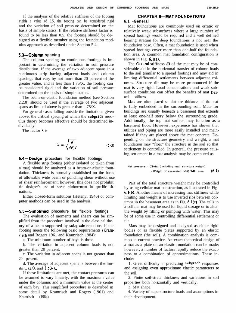
CHAPTER 6-MAT [email protected] -General
Mat foundations are commonly used on erratic orrelatively weak subsurfaces where a large number ofspread footings would be required and a well definedbearing stratum for deep foundations is not near thefoundation base. Often, a mat foundation is used whenspread footings cover more than one-half the founda-tion area. A common mat foundation configuration isshown in Fig. 6.1(a).
The flexural stiffness EI of the mat may be of con-siderable aid in the horizontal transfer of column loadsto the soil (similar to a spread footing) and may aid inlimiting differential settlements between adjacent col-umns. Structure tilt may be more pronounced if themat is very rigid. Load concentrations and weak sub-surface conditions can offset the benefits of mat flex-ural stiffness.
Mats are often placed so that the thickness of the matis fully embedded in the surrounding soil. Mats forbuildings are usually beneath a basement that extendsat least one-half story below the surrounding grade.Additionally, the top mat surface may function as abasement floor. However, experience has shown thatutilities and piping are more easily installed and main-tained if they are placed above the mat concrete. De-pending on the structure geometry and weight, a matfoundation may “float” the structure in the soil so thatsettlement is controlled. In general, the pressure caus-ing settlement in a mat analysis may be computed as
Net pressure = ([Total (including mat) structure weight]
- Weight of excavated soil}/Mat area (6-1)
Part of the total structure weight may be controlledby using cellular mat construction, as illustrated in Fig.6.1(b). Another means of increasing mat stiffness whilelimiting mat weight is to use inverted ribs between col-umns in the basement area as in Fig. 6.1(c). The cells ina cellular mat may be used for liquid storage or to alterthe weight by filling or pumping with water. This maybe of some use in controlling differential settlement ortilt.
Mats may be designed and analyzed as either rigidbodies or as flexible plates supported by an elasticfoundation (the soil). A combination analysis is com-mon in current practice. An exact theoretical design ofa mat as a plate on an elastic foundation can be made;however, a number of factors rapidly reduce the exact-ness to a combination of approximations. These in-clude:
1. Great difficulty in predicting subgrade responsesand assigning even approximate elastic parameters tothe soil.
2. Finite soil-strata thickness and variations in soilproperties both horizontally and vertically.
3. Mat shape.4. Variety of superstructure loads and assumptions in
their development.

226.21*10 MANUAL OF CONCRETE PRACTICE
5. Effect of superstructure stiffness on mat (and viceversa).With these factors in mind, it is necessary to designconservatively to maintain an adequate factor of safety.The designer should work closely with the geotechnicalengineer to form realistic subgrade response predic-tions, and not rely on values from textbooks.
There are a large number of commercially availablecomputer programs that can be used for a mat analy-sis. AC1 Committee 336 makes no individual programrecommendation since the program user is responsiblefor the design. A program should be used that the de-signer is most familiar with or has investigated suffi-ciently to be certain that the analyses and output arecorrect.
6.1.1 Excavation heave-Heave or expansion of thebase soil into the excavation often occurs when exca-vating for a mat foundation. The amount depends onseveral factors:
a. Depth of excavation (amount of lost overburdenpressure).
b. Type of soil (sand or clay)-soil heave is less forsand than clay. The principal heave in sand overlyingclay is usually developed in the clay.
c. Previous stress history of the soil.d. Pore pressures developed in the soil during exca-
vation from construction operations.The amount of heave can range from very little-%
to 2 in. (I2 to 50 mm)-to much larger values. Ulrichand Focht (1982) report values in the Houston, Tex.,area of\as much as 4 in. (102 mm). Some heave is al-
Plan
Elevation
(a) Solid mat of reinforced (b) Mat using cell (c) Ribbed mat used toconcrete; most common construction. Cells control bendingconfiguration. D = depth may be filled with with minimum con-
most immediately recovered when the mat concrete isplaced, since concrete density is from I.5 to 2.5 timesthat of soil.
The influence of heave on subgrade response shouldbe determined by the geotechnical engineer workingclosely with the structural designer. Recovery of theheave remaining after placing the mat must be treatedas either a recompression or as an elastic problem. Ifthe problem is analyzed as a recompression problem,the subsurface response related to recompressionshould be obtained from the geotechnical engineer. Thesubsurface response may be in the form of a re-compression index or deflections computed by the geo-technical engineer based on elastic and consolidationsubsurface behavior. If the recovery is treated as anelastic problem, the modulus of subgrade reactionshould be reduced as outlined in Section 6.8, where theconsolidation settlement used in Eq. (6.8) includes theamount of recompression.
6.1.2 Design procedure-A mat may be designed us-ing either the Strength Design Method (SDM) or work-ing stress design according to the Alternate DesignMethod (ADM) of AC1 318-83, Appendix B. The ADMis an earlier method, and most designers prefer to usethe SDM.
The suggested design procedure is to:I. Proportion the mat plan using unfactored loads
and any overturning moments as
CPqcBZ I*%*%
( z >(6-2)
Elevation Elevation
for shear, moment or stab-ility an$ ranges from about1.5 to 6 ft (0.5 to 2+ III).
water or sand to con-trol settlements or forstability.
crete. Ribs maybe either one ortwo-way.
Fig. 6. I--Mar configurations for various applications: (a) mat ideally suited for finite element or finite grid method;(b) mat that can be modeled either as two parallel plates with the upper plate supported by cell walls modeled assprings, or as a series of plates supported on all edges; and (c) mat ideally suited for analysis using finite grid method,since ribs make direct formulation of element properties difficult

ANALYSIS AND DESIGN OF COMBINED FOOTINGS AND MATS 336.2~.11
The eccentricity e,, e, of the resultant of column loadsC P includes the effect of any column moments and anyoverturning moment due to wind or other effects. Theeccentricities e,, e, are computed using statics, sum-ming moments about two of the adjacent mat edges[say, Lines O-X, O-Y of Fig. 6.1(a)]. The values of de-sign e,, e, will be slightly different if computed usingunfactored or factored design loads.
The actual unfactored loads are used here as thecomparison to the soil pressure furnished by the geo-technical engineer is
9 G 9”
The allowable soil pressure may be furnished as oneor more values depending on long-term loading or in-cluding transient loads such as wind and snow. The soilpressure furnished by the geotechnical engineer is useddirectly in the ADM procedure. For strength design itis necessary to factor this furnished allowable soil pres-sure to a pseudo “ultimate” value, which may be doneas follows
9 9.sum of factored design loads
I,,, =s u m of unfactored design loads
(6-3)
2. Compute the minimum mat thickness based onpunching shear at critical columns (corners, sides, inte-rior, etc.), refer to Fig. 6.1(a), based on column loadand shear perimeter. It is common practice not to useshear reinforcement so that the mat depth is a maxi-mum. This increases the flexural stiffness and increasesthe reliability of using Eq. (6-2).
3. Design the reinforcing steel for bending by treat-ing the mat as a rigid body and considering strips bothways, if the following criteria are met!
a. Column spacing is c 1.75/X, or the mat is verythick.
b. Variation in column loads and spacing is notover 20 percent. For mats not meeting this cri-teria, go immediately to Step 4.
These strips are analyzed as combined footings withmultiple columns loaded with the soil pressure on thestrip, and column reactions equal to the factored (orunfactored) loads obtained from the superstructureanalysis. Since a mat transfers load horizontally, anygiven strip may not satisfy a vertical load summationunless consideration is given to the shear transfer be-tween strips. Bowles (1982) illustrates this problem anda method of analysis so the strips satisfy statics.
4. Perform an approximate analysis (Shukla 1984) ora computer analysis of the mat and revise the rigidbody design as necessary. An approximate analysis canbe made using the method suggested by AC] 336.2R-66to calculate moments, shears, and deflections in a matwith the help of charts. Charts for this procedure aregiven in Shukla (1984) and Hetenyi (1946). A com-pleted example problem is given in the paper to assistthe designer. The geotechnical engineer should furnishthe designer subgrade respdnse values even when a sim-plified design method is used.
Computer analysis for mat foundations is usuallybased on an approximation where the mat is dividedinto a number of discrete (finite) elements using gridlines. There are three general discrete element formula-tions which may be used:
a. Finite difference (FD).b. Finite grid method (FGM).c. Finite element method (FEM).
These latter two methods can be used for mats withcurved boundaries or notches with re-entrant corners asin Fig. 6.2. All three of these methods use the modulusof subgrade reaction k, as the soil contribution to thestructural model. This has been considered in Sections2.3, 3.3, and 5.4, and will be considered in Sections 6.7and 6.8. Computers (micro to mainframe) and avail-able software make the use of any of the discrete ele-ment methods economical and rapid. The finite ele-ment model shown in Fig. 6.2(b) indicates a simplegridding that produces 70 elements, 82 nodes, and 246equations with a band width computed as shown.
6.2-Finite difference methodThe finite difference method is a procedure which
provides quite good results for the approximationsused. This procedure was used extensively in the past,but is sometimes used to verify finite element methods.It is particularly appealing since it does not requiremassive computer resources. Fig. 6.3 shows the finitedifference method with node equation for interior nodegiven.
6.3-Finite grid methodThis method discretizes the mat into a number of
beam-column elements with bending and torsional re-sistance (Fig. 6.4). The torsional resistance is used toincorporate the plate twist using the shear modulus G.In finite element terminology, the FGM produces non-conforming elements, i.e., interelement compatibility isinsured only at the nodes. A theoretical development ofthis method specifically for mats is found in Bowles(1974, 1976, and 1982).
6.4-Finite element methodThis method discretizes the mat into a number of
rectangular and/or triangular elements (Fig. 6.5). Ear-lier programs used displacement functions which pur-ported to produce conforming interelement compatibil-ity (i.e., compatibility both at nodes and along elementboundaries between adjacent elements).,
For bending, the nodal displacement and slopes inthe X- and Y-direction are required. This results in tak-ing partial derivatives of the displacement function:First, however, one must delete one term for the trian-gle or add two nodes and use the fifteen-term displace-ment function. Similarly, for the rectangle one mustdrop three terms or add a node. There are computerprograms which drop terms, combine terms, and addnodes. Any of the programs will give about the samecomputed output so the preferred program is that onemost familiar to the user.

336.2R.12 MANUAL OF CONCRETE PRACTICE
Nodes 1 2 3 4 5 6 7 8
This grid p r o d u c e s 7 0 e l e m e n t s , 8 2 n o d e s . 2.6
equations
Barldwldth oepends o n n o d e numberlng
scheme - 3Clargest e l e m e n t n o d e
difference + 1)iiere, bandvl t h - 3(37 + 25 +I) I 39
b . F,nite elemenr m o d e l f o r m a t “a.*’ Curved
a r e a h a s b e e n r e p l a c e d v>th a series o fsrralght s e g m e n t s , a n d triangles ere urllazed.
Grtddlng s h o w n h e r e 1s to lllusrrate m e t h o d o f
modeling a n d m a y requre refinement I” some
cases.
Fig. 6.2-Mat gridding for either finite grid or finite element method
6.4.1 Iso-parametric elements-An element is of theiso-parametric type if the same function can be used todescribe both shape and displacement. Some computerprograms suitable for mat (or plate) analysis use thismethodology. The method is heavily computation-in-tensive but has a particular advantage over displace-ment functions in that any given element may contain adifferent number of nodes than others as illustrated inFig. 6.5.
Interpolation functions are used together with an ap-proximation for area integration. Good results areclaimed with care in using enough interpolation points.
Some programs using the iso-parametric formulationmay not have the necessary routines to include extranodes on select elements and in these cases there is usu-ally no advantage of the iso-parametric element overthe displacement function approach. Neither of theseapproaches is exact, unless substantial effort is ex-pended.
Cook (1974), Ghali and Neville (1972), and Zien-kiewicz (1977) describe formulation of the finite ele-ment stiffness matrix.
Advantages of the FEM include:a. The solution is particularly mathematically effi-
cient .b. Boundary condition displacements can be mod-
eled.c. The iso-parametric approach can allow use of mid-
side nodes, which produces some mesh refinementwithout the large increase in grid lines of the othermethods.
“BL wB 5
hWBB
For r - 1: 20(vo + ksh*/D) - 8(wT + wB + VR + wL)
+ 2bTL + WTR + WBL + WBR)
+(w +wTT B B + vLL + YRR) - Ph’ID
Fig. 6.3-Finite difference method with node equationfor interior node given. Separate equations are re-quired for corners, sides, and first nodes in from sides
Disadvantages of the FEM include:a. The formulation of the stiffness matrix is compu-
tationally intensive.b. It is very difficult to include a concentrated mo-
ment at the nodes as the methodology uses moment perunit of width.

ANALYSIS AND DESIGN OF COMBINED FOOTINGS AND MATS 336.2R.13
PI, Pz, PI+, PS - moment (Xi = 8,)
typical beam element withtorsion included.
AZ)
Start node coding atleft corner of mat
upper
Fig, 6.4-Element coding for nodes atid elemenr forces for rhe finite grid merhod. Dimensions B and t used bothfor element moment of inertia i and torsion inertia J
The FEM plate element
M: $ M, etc In general
p2
P t Nodesamenodenode
M'Y
- x2 1 -I MY
2-
MXY
P-X coding hasrelationship toforces and dlsp-
lacements as in Fig. 6-4.
Additional nodes are allowed with some programswhere isoparametric elements using shape functionsare programmed.
Fig. 6.5-Typical rectangular finire elemenr using rhe FEM plate formulation.Continuing P,-X, coding counterclockwise around rhe four-node element givestwelve element displacements: four translations and eight rorarions

336.2R.14 MANUAL OF CONCRETE PRACTICE
Gridding through a column centeras comnly done (typically column 1
of Fig. 6-2.
b. Gridding through columnfaces when column is “fixed”with boundary conditionsinput of Bxshown.
= lily = 0 as
Pro-rating a column axial load (ormoment to adjacent nodes when grid
lines are not on column.
Fig. 6.6-Procedures for modeling columns and column loads into one of rhe dis-Crete (finite) element procedures
c. Often a statics summation of nodal moments isonly approximated. This is often the case where thecommon elements include triangles or a mix of trian-gles and rectangles.
d. It requires interpretation of the plate twist mo-ment A4, that is output.
e. It is not directly amenable to increasing the nodaldegree-of-freedom from three to six for pile caps as isthe finite grid method (FGM).
f. The stiffness matrix is the same size as the FGMbut three times the size of the FD method.
The FEM is particularly sensitive to aspect ratios ofrectangular elements and intersection angles of trian-gles. In practical problems, the designer has little con-trol over these factors other than increasing the gridlines (and number of nodes). For example, Elements A,B, and C of Fig. 6.2 may not give reliable computedresults. This deficiency may be overcome for that ex-ample by adding grid lines, but this is at the expense ofincreasing user input and a rapid increase in the size ofthe stiffness matrix since it increases at three times thenumber of nodes.
6.5-Column loadsColumns apply axial loads, shears, and moments to
a mat. Generally the shear is neglected since its effect
would be to slide the foundation laterally. There couldalso be a tendency to compress the mat between twocolumns; however, the AE,/Z term is so large that thismovement is negligible and can be ignored.
There is no practical way to incorporate horizontalloads into the mat, except at the expense of additionalcomputations. For example, the FGM would require sixdegree-of-freedom nodes to allow this. This representsprohibitive effort for the results-except for pile caps,where some (or all) of the horizontal shear force maybe assumed to be carried by the piles.
The mat may be gridded through the column centers(Fig. 6.6) with any of the methods. If column fixity,zero rotation, at the four column nodes of Fig. 6-6(b)is modeled, the grid lines must be taken through thecolumn faces for the FGM or FEM.
If the column lies within the grid spacing, the adja-cent nodes are loaded with a portion of the load. Thesimple beam analogy shown in Fig. 6.6(c) is sufficientlyaccurate and may be used for both axial load and col-umn moments.
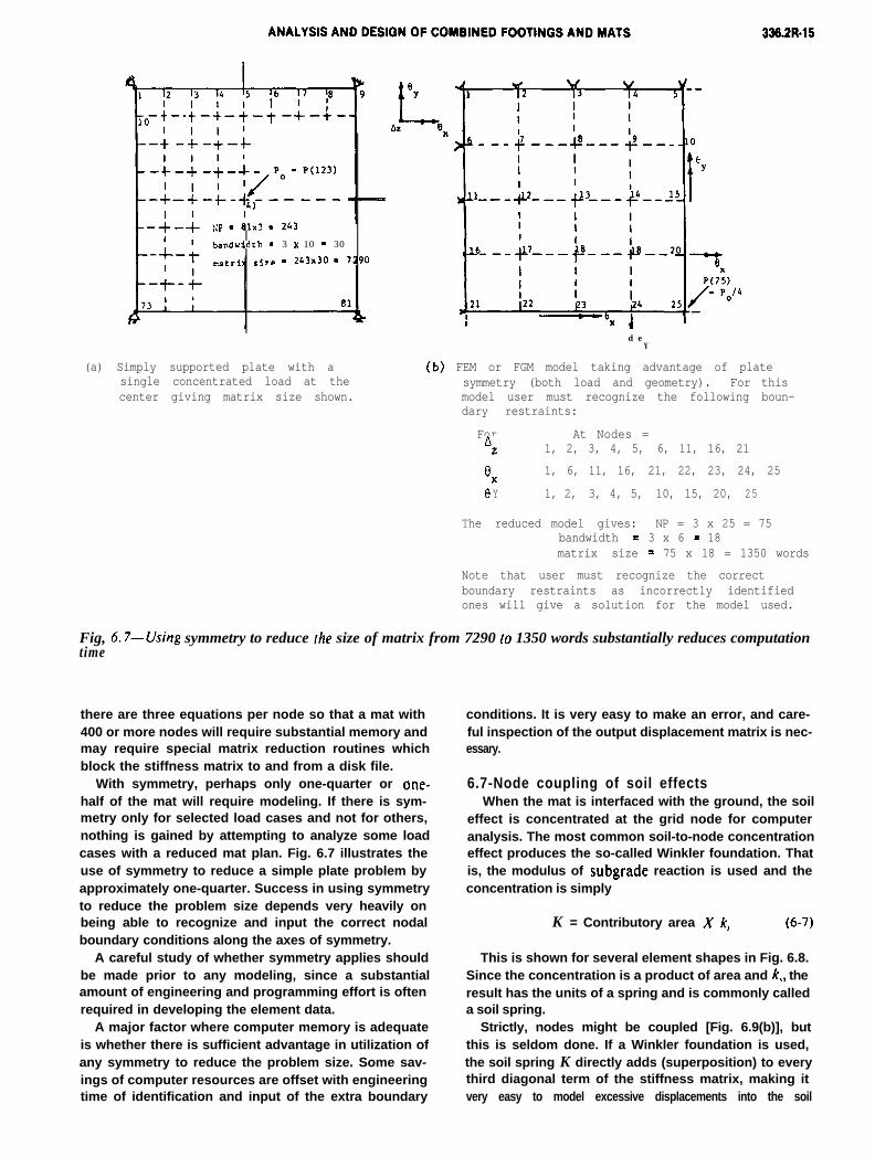
6.6-SymmetryConsideration should be given to any mat symmetry
to reduce the total number of nodes to be analyzed.This is critical in the FGM and FEM in particular since
336.2R-15
- 81x3 = 243
bandwidth - 3 X 10 - 30
- 2&3x30 - 7:90
(a) Simply supported plate with asingle concentrated load at thecenter giving matrix size shown.
d eY
(b) FEM or FGM model taking advantage of platesymmetry (both load and geometry). For thismodel user must recognize the following boun-dary restraints:
ForAz
0
8xY
At Nodes =1, 2, 3, 4, 5, 6, 11, 16, 21
1, 6, 11, 16, 21, 22, 23, 24, 25
1, 2, 3, 4, 5, 10, 15, 20, 25
The reduced model gives: NP = 3 x 25 = 75bandwidth = 3 x 6 = 18matrix size = 75 x 18 = 1350 words
Note that user must recognize the correctboundary restraints as incorrectly identifiedones will give a solution for the model used.
Fig, 6.7-Using symmetry to reduce the size of matrix from 7290 lo 1350 words substantially reduces computationtime
there are three equations per node so that a mat with400 or more nodes will require substantial memory andmay require special matrix reduction routines whichblock the stiffness matrix to and from a disk file.
With symmetry, perhaps only one-quarter or one-half of the mat will require modeling. If there is sym-metry only for selected load cases and not for others,nothing is gained by attempting to analyze some loadcases with a reduced mat plan. Fig. 6.7 illustrates theuse of symmetry to reduce a simple plate problem byapproximately one-quarter. Success in using symmetryto reduce the problem size depends very heavily onbeing able to recognize and input the correct nodalboundary conditions along the axes of symmetry.
A careful study of whether symmetry applies shouldbe made prior to any modeling, since a substantialamount of engineering and programming effort is oftenrequired in developing the element data.
A major factor where computer memory is adequateis whether there is sufficient advantage in utilization ofany symmetry to reduce the problem size. Some sav-ings of computer resources are offset with engineeringtime of identification and input of the extra boundary
conditions. It is very easy to make an error, and care-ful inspection of the output displacement matrix is nec-essary.
6.7-Node coupling of soil effectsWhen the mat is interfaced with the ground, the soil
effect is concentrated at the grid node for computeranalysis. The most common soil-to-node concentrationeffect produces the so-called Winkler foundation. Thatis, the modulus of subgrade reaction is used and theconcentration is simply
K = Contributory area X k, (6-7)
This is shown for several element shapes in Fig. 6.8.Since the concentration is a product of area and k,, theresult has the units of a spring and is commonly calleda soil spring.
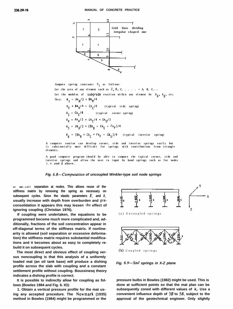
Strictly, nodes might be coupled [Fig. 6.9(b)], butthis is seldom done. If a Winkler foundation is used,the soil spring K directly adds (superposition) to everythird diagonal term of the stiffness matrix, making itvery easy to model excessive displacements into the soil
336.213-16 MANUAL OF CONCRETE PRACTICE
r. Nr(
m f
C c Grid lines dividing
a zirregular shaped mat
N I
B F
(t
Compute spring constants Ki as follows:
Let the area of any element such as A. B. C, . . . . = A, B, C....
Let the modulus of subgrade reaction within any element be kA, kB. etc.
Then: K1 = AkA/3 + BkB/4
K2 = BkB/4 + CkC/4 (typical side spring)
K3 = CkC/4 (typical corner
K4 = AkA/3 + EkE/4 + DkD/3
KB = AkA/3 + (BkB + EkE + FkF)/4
Kb = (BkB + CkC + FkF + GkG)/4
spring)
(typical interior spring)
A computer routine can develop corner, side and interior springs easily butis substantially more difficult for springs with contributions from triangleelements.
A good computer program should be able to compute the typical corner, side andinterior springs and allow the user to input by hand springs such as for nodes1, 4. and 8 above.
Fig. 6.8-Computation of uncoupled Winkler-type soil node springs
or mat-soil separation at nodes. This allows reuse of thestiffness matrix by removing the spring as necessary onsubsequent cycles. Since the elastic parameters E. and k,usually increase with depth from overburden and pre-consolidation it appears this may lessen the effect ofignoring coupling (Christian 1976).
If coupling were undertaken, the equations to beprogrammed become much more complicated and, ad-ditionally, fractions of the soil concentration appear inoff-diagonal terms of the stiffness matrix. If nonline-arity is allowed (soil separation or excessive deforma-tion) the stiffness matrix requires substantial modifica-tions and it becomes about as easy to completely re-build it on subsequent cycles.
The most direct and obvious effect of coupling ver-sus noncoupling is that this analysis of a uniformlyloaded mat (an oil tank base) will produce a dishingprofile across the slab with coupling and a constantsettlement profile without coupling. Boussinesq theoryindicates a dishing profile is correct.
It is possible to indirectly allow for coupling as fol-lows (Bowles 1984 and Fig. 6. IO):
1. Obtain a vertical pressure profile for the mat us-ing any accepted procedure. The Newmark (1935)method in Bowles (1984) might be programmed or the
( a ) U n c o u p l e d s p r i n g s
(b) C o u p l e d s p r i n g s
Fig. 6.9-Soil springs in X-Z plane
pressure bulbs in Bowles (1982) might be used. This isdone at sufficient points so that the mat plan can besubsequently zoned with different values of k,. Use aconvenient influence depth of 3B to 5B, subject to theapproval of the geotechnical engineer. Only slightly
ANALYSIS AND DESIGN OF COMBINED FOOTINGS AND MATS 33&2R-17
e
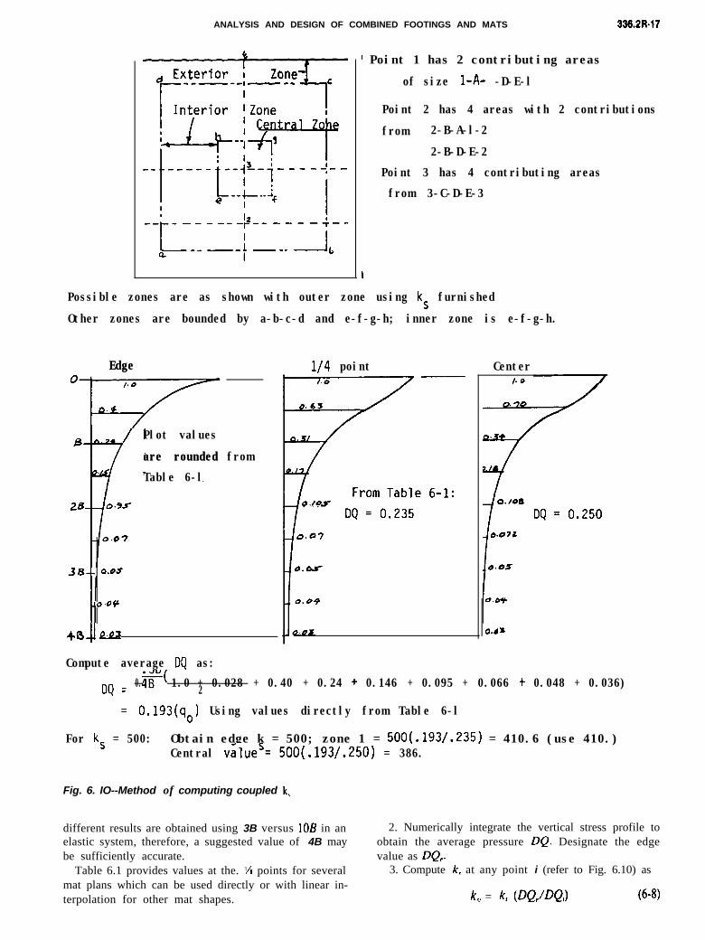
) Point 1 has 2 contributing areas
of size l-A- -D-E-l
Point 2 has 4 areas with 2 contributions
from 2-B-A-l-2
2-B-D-E-2
Point 3 has 4 contributing areas
from 3-C-D-E-3
Possible zones are as shown with outer zone using kS furnished
Other zones are bounded by a-b-c-d and e-f-g-h; inner zone is e-f-g-h.
EdgeEdge
OTG7Plot values
are roundedare rounded
Table 6-l
3/3-- 0.0s
..o .OY
l/4 point
from
Center1. 0
4-B P.0’-lJ 0.0%
Compute average OQ as:
DQ 0.59 4B( 1.0 + 0.028= 2 + 0.40 + 0.24 + 0.146 + 0.095 + 0.066 + 0.048 + 0.036)
= 0.193(qo) Using values directly from Table 6-l
For k, = 500: Obtain edge k = 500; zone 1 = 500(.193/.235) = 410.6 (use 410.)Central values= 500(.193/.250) = 386.
Fig. 6. IO--Method of computing coupled k,
different results are obtained using 3B versus 10B in anelastic system, therefore, a suggested value of 4B maybe sufficiently accurate.
Table 6.1 provides values at the. ‘/s points for severalmat plans which can be used directly or with linear in-terpolation for other mat shapes.
2. Numerically integrate the vertical stress profile toobtain the average pressure DQ. Designate the edgevalue as DQI.
3. Compute k, at any point i (refer to Fig. 6.10) as
k,, = k (DQJDQ,) (6-W

336.2fb18 MANUAL OF CONCRETE PRACTICE
Table 6.1-Vertical pressure profiles by Newmark’s 1935 method (inBowles 1985) for selected points beneath a foundation as shown
B/L = 1
PRESSURE PROFILE FORDY 1
o.OOB 1 .ooo0.50B 0.4001.008 0.2401.508 0.1462.008 0.0952.508 0.0663.00B 0.0483.508 0.0364.008 0.028
POINTS:”
‘ 3 4 51.000 1.000 1.000 1.0000.530 0.628 0.683 0.7010.278 0.309 0.329 0.3360.160 0.170 0.177 0.1790.100 0.105 0.107 0.1080.068 0.070 0.071 0.0720.049 0.050 0.050 0.0510.037 0.037 0.038 0.0380.028 0.029 0.029 0.029
AVERAGE PRESSURE INCREASEDC! = 0.193 0.217
B/L = 2
PRESSURE PROFILE FOR POINTS:DY 1 2
o.OOB 1.000 1.0000.508 0.0408 0.6481.008 0.270 0.3621.508 0.186 0.2292.008 0.135 0.1572.50B 0.101 0.1133.008 0.078 0.0853.50B 0.061 0.0664.00B 0.049 0.052
AVERAGE PRESSURE INCREASEDQ = 0.220 0.273
B/L = 3PRESSURE PROFILE FOR POINTS:DY 1 2
o.OOB 1 .ooo 1.0000.508 0.409 o ,718l.OOB a274 0 ,4081.5OB a195 0.2622.00B a147 0.1852.508 a115 0.1383.008 a092 0.1073.508 a075 0.0854.008 0062 0.069
AVERAGE PRESSURE INCREASEDU = 0.230 0.305
0.235 0.246 0.250
3 4 51.000 1.000 1.0000.757 0.792 t8000.431 0.469 o.4810.263 0.285 0.2930.175 0.186 0.1900.123 0.129 0.1310.090 0.094 0.0950.069 0.071 0.0720.054 0.056 0.056
0.304 0.319 0.324
3 4 51.000 1.000 1.0000.796 0.811 0.8140.486 c.517 O.5250.312 0.340 0.348O.216 0.235 0.2410.157 0.170 0.1740.119 0.127 0.1300.093 0.098 0.100Q075 0.078 0.079
0.340 0.355 0.359
0.5B
tl.OB
The furnished value of k, is taken for the mat perime-ter zone.
4. Assign values of k,, in the interior as practical for
the gridding scheme used for the mat. When doing thistake into account how the nodal springs will be com-puted (refer to Fig. 6.8 and 6.10).
ANALYSIS AND DESIGN OF COMBINED FOOTINGS AND MATS 339.2%19
6.6-Consolidation settlementConsolidation settlement and recompression of heave
can be incorporated into the mat analysis in an approx-imate manner as follows:
In order of increasing difficulty, the suggested pro-cedures are:
1. Compute the estimated consolidation settlementsA H,, at the several points as used for the couplinganalysis. This must also be done for the edge.
1. Using direct area contributions for all springs(common practice but not correct, as stated previ-ously).
2. Make a basic mat analysis (including coupling ifthis is going to be the method used). Inspect output foredge pressures and obtain a best estimate of the edge-pressure average. Also obtain node displacements AH,and estimate node consolidation displacements AH,,.The revised k,: can be computed from the basic defini-tions of k,
2. Doubling the edge springs (not strictly correct, butnot very difficult to program a routine in a mat pro-gram).
3. Using the Boussinesq coupling of Section 6.7. Thisis the most accurate of the approximate procedures, butis also more difficult. Some difficulty can be reducedby programming a routine for most of the mechanicalsteps.
4. Using Methods 2 and 3 in combination.
9, = k,, (AH,) and k:, = q,/(AH, + AH,,)6.10-Computer output
to obtain
k,: = k,, (AH,)/(AH, + AH,,) (6-9)
The computer program for any of the three methods(finite difference [FD], finite grid method [FGM], orfinite element method [FEM] should output:
3. Run the mat analysis with these new zoned valuesof k,;. Output will include effect of consolidation set-tlement. Edge nodes should compute a displacementapproximately equal to the computed consolidationsettlement from Step 2.
I. X and Y bending moment summations at all nodesso that a statics check can be quickly made at pointswhere this summation should be zero.
2. The displacement matrix. This should be routinelychecked for any symmetry and points of known dis-placements (if any).
The problem may be cycled several times since theconsolidation settlement computed depends on the matcontact pressure, which may change as computationsprogress.
3. Nodal soil reactions (forces) computed as
Force = Node spring x Displacement (6-10)
Since the consolidation settlement is time-dependent The node forces should be computed, summed, andit may be appropriate (depending on time for consoli- compared to the sum of the vertical input forces (col-dation) to use a reduced value of E, for the concrete to umn loads and mat weight). Routinely check this toallow for creep effects. within computer roundoff.
4. Nodal soil pressures computed as:6.9-Edge springs for mats
An alternative to using the Boussinesq coupling pro-cedure is to double the exterior edge springs (but notany along edges of symmetry where a part of the mat isanalyzed). This doubling will include some coupling ef-fect and account somewhat for the higher theoreticaledge pressures claimed to develop in cohesive soils be-neath rigid plates. Doubling of springs for a plate witha single column (as a spread footing) tends to givecomputed differences of less than IO percent for mo-ments at the column faces.
9, = k, x Displacement (6-l 1)
The node pressures 9 should not exeed the value rec-ommended by the geotechnical engineer. If the pro-gram considers nonlinear effects, both the node forceand node pressure is limited to some maximum value.Verify that the program uses this by inspecting the dis-placements larger than the limiting value (and any thatindicate soil separation).
Doubling of springs for mats can give differences be-tween computer-generated values as much as 20 per-cent larger with the higher values obtained from dou-bling. A Committee comparison using the FGM and themat given by Shukla (1984) showed that doubling theedge springs produced computed moments about 18 to25 percent higher and that the larger moments gave abetter comparison to the values computed by hand inthat reference.
It should be noted, however, that doubling the edgesprings tends towards the same end result as using theBoussinesq coupling procedure, since the reduction ofthe interior values of k, for a mat is similar to increas-ing the soil resistance at the edge.
If a program is reasonably complete in providing theabove output, the designer can make a rapid check ofthe computations. A check of the mat data (node co-ordinates, etc.) will usually take much longer; however,the check may identify that some input is bad if thecomputed output is grossly in error. Where errorsmight occur, a user should modify the program to print(on demand) the full stiffness matrix (in blocks so thepages can be cut and pasted) to display the matrix forinspection of symmetry. Since the stiffness matrix is al-ways symmetrical and has no zeroes on the diagonal,this provides a good check on the internal program-ming used to develop the stiffness matrix. While thischeck produces a large amount of paper output, thepaper cost is negligible compared to a design error.
336.2~~20 MANUAL OF CONCRETE PRACTICE
6.11 -Two-dimensional or three-dimensionalanalysis
A mat designed as a plate on an elastic foundationusing soil concentrations at the nodes is considered atwo-dimensional analysis (2-D). If the mat is placed onthe soil and the soil is modeled using three-dimensionalsolids, the analysis is termed three-dimensional (3-D).
A 3-D analysis is extremely costly in modeling timeand use of computer resources. At present, computerprograms are not widely available to model the soil asa 3-D continuum and most use has been for nuclearpower plants.
Since any mat analysis is only as good as the soil pa-rameters, it is usually difficult to justify a 5 to IO per-cent computational difference when the soil parametersmay only be estimates or a range of values. This is par-ticularly true if:
a. 3-D analysis cost is four or five times that of a 2-Danalysis.
b. Design personnel are not particularly familiar withthe program or methodology.
The major appeal of a 3-D analysis is for* soil cou-pling. Since coupling can be handled within the preci-sion of the soil response prediction as outlined inSection 6.7, there is little to justify use of a 3-D matanalysis.
6.12-Mat thicknessThe FD and FEM methods imply use of thin plate
theory. While an investigator may question whether a5-ft (1.8 m) mat is a thin plate, a thin plate analysis isgenerally used and is adequate. The FGM methodmakes no assumption on plate thickness but analyzeswhat is given.
A comparison study by Frederick (1957) showed thata plate would have to be quite thick to invalidate the“thin” plate theory model.
6.13-Parametric studiesIt is very difficult for the geotechnical engineer to
provide accurate elastic design parameters for the soil(E,, ~1, and k,). Recognizing this, the structural designerand geotechnical engineer may do a parametric study,varying the value of k, over a range of one-half the fur-nished value to five or ten times the furnished value.
The results of the parametric study should be re-viewed by the geotechnical engineer during the courseof the design. If no satisfactory solution is found, thenadjustments in the development concept may be appro-priate. Adjustments may include: reducing the weightof the structure (change from reinforced concrete tostructural steel), enlarging the mat in plan, or deepen-ing the mat base to reduce the net applied pressure.Such adjustments should be made only with the con-currence of the geotechnical engineer.
6.14-Mat foundation detailing/constructionTo simplify steel placement, it is common practice to
provide a layer of top and bottom reinforcement in
both directions. As localized flexure requirements dic-tate, additional reinforcement is placed in the samelayer, or as additional layers to add strength to the sec-tion. It is essential that the engineer prepare thoroughdrawings documenting all phases of the reinforcementplacement. Splice locations must be shown and lengthsnoted. Specification of placement sequence is very im-portant. To insure structural integrity, short staggeredlap splices should be used instead of long splices occur-ring at one location. On large jobs, No. 14 and No. 18bars may be used to minimize the number of pieces onthe job and to reduce the quantity of bar layers.
CHAPTER 7-SUMMARYThe recommendations given in Chapters 1 through 6
may be used as a guide in analysis and design of com-bined footings (two or more columns in a line) or matfoundations. These recommendations represent thecollective opinion of the Committee members based onboth practice and a survey of published literature. TheCommittee recognizes that it is impossible to cover allfoundation cases likely to be encountered by a designerand no attempt has been made to do this.
The Committee recognizes that the state of the art incomputerized analyses is substantially ahead of theability of engineers to determine soil properties accu-rately. The use of computer methods is recommendedsince they allow parametric studies so that a range ofpossible (or probable) soil responses can be investi-gated.
The Committee concedes that the Winkler founda-tion model can be improved, but the increased compu-tational complexity is not warranted when soil proper-ties are taken into account. For this reason the simplecoupling procedure outlined here which relies on thewidely used Boussinesq theory will generally be ade-quate if some additional computational refinement iswanted.
Computer analyses are generally more efficient thanhand computations - particularly of the beam-on-elastic-foundation type since interpolation of table orcurve values is eliminated. This statement also recog-nizes the current widespread availability of desk-top tomain-frame computer systems.
Finally, the Committee notes that, with the same careand attention to detail, the real advantage of the com-puter approach is the ability to better capture the ef-fects of irregular geometry and foundation flexibility.The keywords are “with the same care.” The analysisand design of a mat foundation is a problem in soil-structure interaction requiring a close working relation-ship between the structural and geotechnical engineer.Although published values of soil response parametersare available, geotechnical engineering analysis andjudgement are needed to make the values meaningful tothe design.

ANALYSIS AND DESIGN OF COMBINED FOOTINGS AND MATS 336.213-21
CHAPTER a--REFERENCES8.1 -Specified and/or recommended referencesAmerican Concrete Institute318-83 Building Code Requirements for(Revised 1986) Reinforced Concrete
8.2 - Cited referencesACI Committee 336, 1966, “Suggested Design Procedures for
Combined Footings and Mats,” Ametican Concrete Institute. De-troit, 13 pp.
Ball, Steven C., and Notch, James S., May 1984, “ComputerAnalysis/Design of Large Mat Foundations,” Journal OJ S~ruc/urul
Engineering, ASCE. V. I 10, No. 5, pp. I I80- I 196.
Banavalkar. P. V., and Ulrich. E. 1.. Jr., 1984. “Republic BankCenter: Structural and Geotechnical Features,” International Con-ference on Tall Buildings, Singapore, OCI.
Bowles, Joseph E.. 1974, Analyrical and Compurer Methods in
Foundufion Engineering, McGraw-Hill Book Co., New York, pp.
154. 155. and 168-170.Bowles. Joseph E.. 1975. “Spread Footings,” Foundurion Engi-
neering Hundbook. Van Nostrand Reinhold Co., New York, Chap-ter IS. pp. 490-491.
Bowles, Joseph E.. 1976, “Mat Foundations” and “Computer
Analysis of Mat Foundations,” Proceedings, Short Course-Seminar
on Analysis and Design of Building Foundations (Lehigh Univer-
sity), Envo Press, Lehigh Valley, pp. 209-232 and 233-256.Bowles, Joseph E.. 1982. Foundation Analysis and Design, 3rd
Edition, McGraw-Hill Book Co., New York, 800 pp.Bowles. Joseph E.. 1983, “Pile Cap Analysis,” Proceedings, 8th
Conference on Electronic Computation (Houston), American Societyof Civil Engineers, New York, pp. 102-I 13.
Bowles, Joseph E.. 1984. Physical and Georechnical Properries oJ
Soil, 2nd Edition, McGraw-Hill Book Co.. New York, 1984. Chap-ter IO.
Christian, J. T., 1976, “Soil-Foundation-Structure Interaction.”Proceedings, Short Course-Seminar on Analysis and Design ofBuilding Foundations (Lehigh University). Envo Press, Lehigh Val-
ley, pp. 149-179.Collatz. L.. 1960, The Numerical Treatmen/ of Dijjerenrial Equu-
lions, 3rd Edition, Springer-Verlag, Berlin.
Cook, R. D.. 1974. Concepts and Applications oJ Finire Elemenr
Anulysis. John Wiley & Sons, New York, 402 pp.Department of the Navy, 1982, “Soil Mechanics.” Design Monuul
NAVFAC DM-7.1, Naval Facilities Engineering Command, Alexan-
dria, pp. 7.1-161 - 7.1-241.Department of the Navy, 1982. “Foundations and Earth Struc-
tures,” Design Manual NAVFAC DM-7.2. Naval Facilities Engi-neering Command, Alexandria, pp. 7.2-129 - 7.2-159.
Focht. John A., Jr.; Khan, Fazlur. R.; and Gemeinhardt. J. Peter,May 1978, “Performance of One Shell Plaza Deep Mat Founda-tion,” Proceedings, ASCE. V. 104. GT5. pp. 593608.
Frederick, Daniel, 1957. “Thick Rectangular Plates on an Elastic
Foundation,” Trunsucrions, ASCE. V. 122, pp. 1069-1085. Also, tee
Discussion, p. 1086. which corrects conclusions presented in paper.
Ghali, A., and Neville, A. M., 1972, Brucrural Analysis: A Uni-
Jied Classicul and Murrix Approach, lntext Educational Publishers
(Now Harper and Row), Chapters 17-20.Haddadin. M. J.. 1971, “Analysis and Design of Foundation Mats
and Combined Footings-Program User’s Manual,” Portland Ce-ment Association, Skokie, 55 pp.
Hetenyi. M.. 1946, Beums on Elastic Foundation, University ofMichigan Press, Ann Arbor, pp. 100-106.
Kramrisch, Fritz, and Rogers, Paul, Oct. l%l, ‘Simplified Design
of Combined Footings,” Proceedings, ASCE, V. 88, SMS, pp. 19-44.Kramrisch. Fritz, 1984, “Footings,” Handbook of Concrefe Engi-
neering, 2nd Edition, Mark Fintel. Editor, Van Nostrand ReinholdCo., New York, pp. 139-168.
Meyerhof, G. G., June 1953, “Some Recent Foundation Researchand its Application IO Design,” The Sfrucfurul Engineer (London), V.31, No. 6.
Newmark. N. M., 1935, “Simplified Computation of Vertical
Pressures in Elastic Foundations,” Experiment Slation Circular No.
24, University of Illinois, Urbana.Schleicher. Ferdinand, 1926, Kreisplarren auf elasrischer Unrer-
loge. Jules Springer, Berlin.Scott, R. F.. 1981, Foundurion Anulysis. Prentice-Hall, Inc.. En-
glewood Cliffs, pp. 150-197.Shukla, Shyam N.. Sept.-Oct. 1984. “A Simplified Method for
Design of Mats on Elastic Foundations,” ACI JOURNAL, froceed-
ings V. 81, No. 5, pp. 469-475.
Sowers, G. F.. 1977, “Foundation Modulus for a Mat on Sand,”Preprinf No. 29371, American Society of Civil Engineers, New York.
Teng. Wayne Chi-Yu. 1962, Foundorion Design, Prentice-Hall,
Inc., Englewood Cliffs, pp. 174-191.Terzaghi, K., Dec. 1955, “Evaluation of Coefficients of Subgrade
Reaction,” Geofechnique (London), V. 5, No. 4, pp. 297-326.Timoshenko, S., and Woinowsky-Krieger, S., 1959, Theory of
f/ores ond She//s, 2nd Edition, McGraw-Hill Book Co., New York,
pp. 259-281.
Ulrich, E.J.. 1988, “Geotechnical Considerations in Mat Founda-tion Design,” Structural and Georechnical Lecrure Series, Illinoissection, ASCE, Chicago.
Ulrich, E. J., and Focht. J. A., 1982. “First City National Bank
IO Texas Commerce Tower: Lessons Learned,” Preprint No. 82-532,
ASCE National Convention (New Orleans), American Society of CivilEngineers, New York.
U.S. Department of the Interior. 1960, “Moments and Reactions
for Reciangular Plates,” Engineering Monogruph No. 27, Bureau ofReclamation, Denver.
Winterkorn, Hans F.. and Fang, Hsai-Yang, 1975. Foundation
Engineering Hundbook. Van Nostrand Reinhold Co., New York, pp.481-555.
Zienkiewicz, 0. C., 1977, The Finite Element Method, 3rd Edi-tion. McGraw-Hill Book Co., New York, 808 pp.
This report was submitted to letter ballot of the committee and was ap-proved according to ACI bal lot ing procedures.

THE FOLLOWING DISCUSSIONS, WHICH WERE PUBLISHED IN THE JANUARY-FEBRUARY 1969 ACIStructural Joununt (PP. ill-116), ARE NOT PART OF THE REPORT ACI 336.2R-66, BUT ARE PROVIDEDAS ADDITIONAL INFORMATION TO THE READER.
Suggested Analysis and Design Procedures for Combined Footings and Mats.Reported by ACI Committee 336
Discussion by Ashraf Habibullah and Edward L. Wilson, John S. Horvath, and Committee
By ASHRAF HABIBULLAH and EDWARD L. WILSONPtvsidcnt. Computers and Structures. Inc.. &rk&y, Caltfomia; Professor ofCivi l Engineering. University of California, Berkeley, California
The committee members deserve high praise andcommendation for producing a report that sets proce-dures for addressing an aspect of structural engineeringthat has always been a source of analytical concern tothe structural engineer.
Practical implementations of the finite elementmethod were originally directed towards applications inthe aircraft industry, therefore the output produced bythe programs was in the form of unit stresses (direct,shear, and principal). Most finite element programs stillretain this form of output, which of course is not in aform that can be directly used by a structural engineerin the design of concrete slabs.
With the advent of personal computers, many of thefinite element formulations have been rewritten andformulated to address specific problems of the struc-tural engineer, e.g., slab analysis and design (Habibul-lah, 1985). The disadvantages of the finite elementmethod that are listed in the subject report are not lim-itations of the method but are problems associated withusing an implementation of the method that is not in-tended to address the analysis and design of slab sys-tems.
With special purpose equation solvers it is now pos-sible to solve 5000 joint, 15,000 equation systems in atime frame of 60 to 90 min.
With special node point forces and moment summa-tion techniques, it is possible to produce design mo-ments and forces that are in complete equilibrium withthe applied loads irrespective of the coarseness of themesh. The static summation of moments and shears al-ways produces exact equilibrium.
The effects of the slab twisting moments can be ef-fectively included by using element joint reactive mo-ments obtained from the stiffness matrixes instead ofthe stress transformation matrixes that produce the in-ternal stresses.
Thick mats may now be modeled with new elementsthat have been developed, which include the effects ofshear deformations.
An important aspect of mat analysis that was notaddressed in the subject report is foundation uplift.Most computer programs address this problem by soilspring disconnection resulting in multiple reductions ofthe stiffness matrix. Such an algorithm is obviouslyslow and allows only one load case to be included. Newtechniques have been implemented whereby it is possi-
ble to negate the uplift effects by iterating on the loadvectors with no modifications of the stiffness matrix,thereby also allowing multiple load cases to be consid-ered simultaneously.
In conclusion, it is important to emphasize that,from an analytical point of view, slab systems are avery special class of structures. A special purpose pro-gram that recognizes these characteristics will not onlyproduce a better solution algorithm but will offer sig-nificant savings over general purpose computer pro-grams in the time associated with the definition of theinput, interpretation of the output, and executionthroughout.
REFERENCEHabibullah, A., “SAFE-Slab Analysis by the Finite Element
Method,” Computers and Structures, Inc., Berkeley. 1985.
By JOHN S. HORVATHMembrr American Concrete Inst i tute , Asspciote Prof+?sor. ManhattanCoFkge, School of Engineer ing, Civi l Engtnuring Lbpartment. Bronx. New
The committee is to be commended for preparing thisupdated summary and guideline of the state of practicein this important segment of foundation engineering.Keeping in mind that this is meant to be a pragmatic,design-oriented document, the writer has comments infour areas.
First, considerable emphasis is placed on the differ-ent contact stresses between coarse- and fine-grainedsoils (Sections 2.2.1, 2.2.6; Fig. 3.1). In the writer’sopinion, these comments can be found in many foun-dation engineering textbooks and can be traced back tomodel and small-scale surface testing that was gener-ally performed 50 or more years ago. Actual founda-tion elements have, with few exceptions, relatively sig-nificant depths of embedment that should preclude thenear-zero stresses in coarse-grained soil. In any event,there is a lack of well-detailed case histories on rela-tively rigid, full-size foundation elements that wouldprovide more meaningful insight on the subject. There-fore, the use of nonrepresentative test results is mis-leading.
Second, in Section 6.4.1, the reported disadvantageof the finite element method (FEM) with respect toconcentrated moments at nodes should be revised alongthe lines of Bowles (1987) and Darwish (1987).

236.2W02 MANUAL OF CONCRETE PRACTICE
Third, the writer concedes that Young’s modulus forsoil is not an easy parameter to determine, as it is afunction of confining stress and stress level as a mini-mum. However, the writer believes that the committeeis unduly pessimistic and discouraging to users of thereport in this regard. Increasing sophistication in in situsoil testing has permitted advances in determining theYoung’s modulus of soil, and even such relatively crudetests as the Standard Penetration Test can be useful. Areview of several methods for determining the coeffi-cient of subgrade reaction for plate-type foundationelements (e.g., mats) (Horvath 1979, 1983b, 1988a,1988~) and beam-type foundation elements (e.g., com-bined and continuous footings) (Horvath 1988b, 1988d)indicated that the most useful and accurate methodsrequire a reasonable estimate of Young’s modulus forthe soil.
Finally, the writer believes that the report shouldemphasize the considerably different sensitivity ofbending moments and settlements to the value of kwhen using Winkler’s hypothesis. The writer agreescompletely with the suggestion in Section 6.13 that adesign be made based on varying k in the analyses.While some relatively modest range in bending mo-ments will result (and can be accommodated easily byconservatively sizing and placing the reinforcing), therange in estimated settlements will be of the same orderof magnitude as the range in k values, e.g., a range of20 to use the example in Section 6.13. In most cases,this would result in an estimated range in settlementsthat would be considered excessive. This only illus-trates a generally forgotten recommendation by Ter-zaghi (1955) that Winkler’s hypothesis be used only forcalculating local bending moments and not settlements.In view of the generally poor accuracy of Winkler’s hy-pothesis as a subgrade model for total analysis of mat-and beam-type foundation element behavior, the writerbelieves that improvements to Winkler’s hypothesis arejustified and, in fact, long overdue. The writer agreesthat 3-D analyses techniques are not warranted, but re-search (Horvath 1979, 1983a) shows that relatively sim-ple but powerful 2-D models (more properly calledboundary element or surface element models [Tomlin-son 1986, p. 3231) are available. The soil-property datarequired are, in fact, no more than that required formost estimates of Winkler’s k value, i.e., a reasonableestimate of Young’s modulus of the soil. While someinvestigation and computer code development for thesemore advanced 2-D models stili remains to be done (butis under development at the present time), the primaryobstacle in the writer’s opinion to their use in routinedesign will be the tremendous inertia of displacingWinkler’s hypothesis.
REFERENCESBowles, Joseph E.. Sept.-Oct. 1987, Author’s Closure to Discus-
sion of “Mat Design” by Joseph E. Bowles, AC/ Structurd Journal,V. 84. No. 5. p. 449.
Darwish. M. Nasser, Sept.-Oct. 1987. Discussion of “Mat De-sign” by Joseph E. Bowles, AC1 Structural Journal, V. 84, NO. 5, p.449.
Horvath, J. S.. 1979, “A Study of Analytical Methods for Deter-mining the Response of Mat Foundations 10 Static Loads,” PhDthesis, Polytechnic Institute of New York, Brooklyn.
Horvath, John S., Dec. 1983a. “New Subgrade Model Applied toMat Foundations,” Journal of Geotechnical Engineering, ASCE. V.109. No. 12, pp. 1567-1587.
Horvath. John S., Dec. 1983b. “Modulus of Subgrade Reaction:New Perspective,” Journal of Geotechnical Engineering, ASCE. V.109. No. 12. pp. 1591-1596.
Horvath. J. S., l988a, “Further Evaluation of the Coefficient, orModulus, of Subgrade Reaction, k. Using an Extension of Reissner’sSimplified Elastic Continuum Concept,” Reseurch Report No. CE/GE-88-2, Manhattan Col lege, Bronx.
Horvath. J. S., 1988b. “Determination of the Coefficient ofSubgrade Reaction, k, for Beams,” Research Report No. CEXE-88-3. Manhattan Col lege, Bronx.
Horvath, J . S . . l988c, “Subgrade Reaction: New Perspective-Part2,” submitted for publication to the ASCE Journal of GeotechnicdEngineering.
Horvath, J. S., l988d, “Winkler’s Hypothesis and Beam-TypeFoundations,” submitted for publication to the ASCE Journd ofGeotechnical Engineering.
Terzaghi, K., 1955, “Evaluation of Coefficients of Subgrade Re-action,” Geotechnique (London), V. 5, No. 4. pp. 297-326.
Tomlinson, Michael J., 1986. Foundution Design and Construc-lion, 5th Edition, Longman Scientific & Technical/John Wiley &Sons, New York.
COMMITTEE CLOSUREThe committee wishes to thank the discussers for
their interest. In responding to the comments, how-ever, we must first be mindful of the document’s ob-jective, scope, and users.
AC1 336.28-88 and its 1966 predecessor are docu-ments that offer guidance primarily to the structuralengineer in the design of both combined footings andmat foundations. The document is not intended to be ahandbook nor design manual, but a document that em-phasizes important features that may or may not be in-cluded in textbooks. An important objective that isachieved is the emphasis that the analysis and design ofcombined footings and mats is a soil-structure interac-tion problem in which significant simplifications andidealizations are needed by two design team memberswho must work together closely: the structural engineerand geotechnical engineer.
Like all contributions made by a committee, theproduct is a compromise formulated by hours of delib-eration by distinguished researchers and practitioners.The members of Committee 336 that prepared AC1336.2R-88 included structural engineers, foundationengineers, and geotechnical engineers who have ago-nized over the design of combined footings and mats inengineering practice related to simple and difficultprojects.
GENERALThe most important parameter in the analysis and
design of combined footings and mats is the subgraderesponse (Banavalkar, 1988). Subgrade response hastraditionally followed the theory of subgrade reaction(Terzaghi, 1955), which was first introduced by Wink-ler in 1867 to improve the analysis of the mat or com-bined footing. In the theory of subgrade reaction, the

ANALYSIS AND DESIGN OF COMBINED FOOTINGS AND MATS 336.2R-D3
subgrade reaction is modeled as linear springs and ad-justments are made to the selected value based onembedment, depth, and geometry (Terzaghi, 1955;Teng, 1%2).
Although the theory of subgrade reaction has beenused successfully and probably will continue to be used,experience (Focht, et al, 1978; Banavalkar and Ulrich,1984 and 1986; Ulrich, 1988) with large, complex matfoundations has shown that use of the theory ofsubgrade reaction in its classical form can give mislead-ing results and really should not be used in the analy-sis. In overconsolidated soil environments, the most se-vere bending moments have shown to come from foun-dation movement under fixed or sustained loadingconditions when the mat is loaded to modest pressures.The subgrade response may be quasi-elastic or elastic-plastic instead of purely elastic. Mat deflections mayoccur during the application of fixed loads or over sev-eral years depending on the load system and subsurfaceconditions.
The theory of subgrade reaction can be extended be-yond the classical form using the Discrete Area Method(Ulrich, 1988) to properly consider the loading condi-tions and associated subgrade response. Still, the mostelusive element of the analysis is the prediction ofsubgrade response partly because of the limitations instructural load prediction and partly due to the limita-tions in predicting subgrade behavior. Theories of elas-ticity, quasi-elasticity, elastic-plastic, and finite ele-ments are appropriate in analyzing subgrade response,and the use of a theory will depend on the geologic en-vironment coupled with the experience of the geotech-nical engineer and the character of the foundation sys-tem.
Probably the most disturbing concept to emerge inthe analysis and design of combined footings and matsis the zeal to model the subgrade by a single parametersuch as Young’s Modulus, K, or a modulus based onexperience or mysticism. The fact remains, however,that the analysis of a combined footing or mat is in-deed complex and that for every pound of structuraltheory there must be an ounce of geologic theory thatis as important as yeast is to making bread. An inti-mate knowledge of construction details and the resultsof extensive construction observations with behaviormeasurements are needed to predict subgrade response.Without this level of effort by the geotechnical engi-neer, the analysis and design of combined footings andmats is at best a guess.
Contact stresses related to soil type - Sections2.2.1 and 2.2.6
The document really does not give considerable em-phasis to the character of contact stresses and the rela-tionship to soil characteristics. The information is pre-sented to emphasize to the structural engineer the sim-plifications made related to contact stresses and theinherent variability related to soil character orimarilyfor combined footings. Depths of foundation embed-ment can be almost negligible, depending on the devel-
opment requirements. Many structural designers do notread foundation engineering textbooks; hence, the in-formation included in the new document should in-clude information that is found in foundation engi-neering texts.
Section 6.4.1 - Disadvantage of the FEM withrespect to concentrated moments at nodes
Professor Horvath correctly notes the misconceptionconcerning the input of node moments into the FEM.Node moments can be directly input into the model.The problem is in later trying to do a rapid statics checksince the element moments output are in units of mo-ment/unit of width. About all one can do after makingproper allowance for M, is to inspect the M,, M, val-ues at common nodes for reasonably close agreement.Adjacent element values at a common node often donot agree very closely. With the FGM it is much easierto make a nodal statics check since the node unbalancefrom the element moments framing into the node isequal to the input node moment (if any or is zero oth-erwise). Also the algebraic sum of all element shearsinto the node plus soil reaction minus vertical inputnode force (if any) equal zero for another sometimesuseful statics check. Finally, the element end shear di-vided by the element width can be used to check if themat is thick enough.
The use of a fairly wide range of constant values ofk, has not been found to produce very large differencesin computed plate bending moments. Also, comparisonof bending moments using “coupled” versus constantk, displays differences seldom over 20 percent and oftenunder 10 percent. These small differences result fromthe mat EI (or stiffness) being several orders of magni-tude larger than the soil (or else why use a mat) so itsrigidity predominates; it also results from the distribu-tion of mat loads. These factors account, at leastpartly, for the popularity of using the subgrade modu-lus model. The committee agrees, as noted in the re-port, that a uniformly loaded plate should deflect morein the center than at the edges and was the reason forsuggesting coupling in the first place. The two couplingmethods suggested are simple to model, easily uncier-stood, and can include the long-term effect of soil con-solidation, if necessary. In any case, the report did notsuggest that it was necessary to use a single value of k,,and it was noted that recycling may be necessary (asalso required if nonlinearity is considered-either mat-soil separation or for excessive deflections).
If the coupling methods given in the report are notdeemed satisfactory, give consideration to the alterna-tive simple procedure outlined in Bowles (1988). whichprovides somewhat softer interior node springs andedge springs close to two times the interior ones. Thisprocedure is based on the settlement equation given inthis report but additionally including the Fox embed-ment depth factor IF. The equation is rewritten as

338.2R-04 MANUAL OF CONCRETE PRACTICE
or since k, = Aq/AH, obtain AH/Aq = B(l - $)1,&/Es. By obtaining AH/Aq at several points beneath themat, we can obtain several zones of a different butconstant KS where in each the modulus of subgrade re-action is
k, = l/(m/Aq)
In Bowles (1988, example lo-2), because of readyavailability we have
Point
Center 1 0.039 (0.037) 1 26 (= l/0.039)
Edge 0.023 (0.022) 43.5 (= l/0.023)
These values are from a computer program which re-fined the factor Ic and carried more digits. Text valuesare in parenthesis. We see that most of the interior partof the mat (of B x L = 45 x 45 ft) has a softer k,, andthe exterior defined by the edge is on the order of 43.V26 = 1.7 times stiffer. This mat also had a limited in-fluence depth H = 89 ft to rock so we probably shouldnot normalize the values to obtain permanent ratios forall cases. This data shows the edge k, (and resultingnode springs) is nearly 1.7 time stiffer than the interior.In a general case (without benefit of a computer pro-gram), this shows there is a reasonable theoretical vali-dation of the concept of doubling the edge springs tomodel coupling with adequate accuracy. For highestaccuracy, one should make a computation such as theprevious one for the given problem conditions. Thecomputed settlements should be as reliable as those ob-tained from the elastic settlement equation since it isbeing used to obtain k,.
For mats with variable loadings it may be necessaryto recycle several times to obtain k, compatible for theloading pattern, since the base contact pressure for thatpoint (or zone) Aq is in the ratio MZ/Aq.
The value of Es used in the previous settlement equa-tion should be obtained as outlined in Bowles (1987).That is, it should be a weighted value that considersstratification and a different Es in each stratum for adepth H = 5B or a depth to the hard stratum if lessthan 5B. Hard was suggested as having an Es on the or-der of 10 times E, of the upper adjacent stratum.
Any of these “coupling” procedures are similar tothat of Horvath (1983) since any coupling has the ef-fect of producing softer interior node soil springs.From the limited methodology given in Horvath (1983),his method did not appear to offer any advantages tothe more simple, direct, and easy-to-modify methodsfinally suggested by the committee. The basics of thiscoupling method had been presented much earlier byBowles (in 2nd edition [1977] of 1988).
It is certainly not unreasonable in mat design to usea width range of likely values of k, to see resulting plateresponse. This allows one to ascertain the relative im-portance of the several design parameters on bothbending and settlements. Again note that the commit-tee did not suggest that the designer must use a singleor a constant value of k,. It is suggested that if one ob-tains k, using the elastic settlement equation and thecontact pressure Aq is correctly defined and allowanceis made for consolidation settlements as outlined in thereport, the computed settlement is probably as good avalue as likely to be estimated in advance of construc-tion by any other procedure.
The committee recognized that the direct applicationof node springs does not always produce a good foun-dation model and for this reason suggested giving con-sideration to some kind of spring coupling. Here is, ofcourse, where immediate conflict occurs since anyonewho has some kind of computer program or analyticalprocedure always has the “best possible” solution-re-gardless of their model limitations or how complexand/or little understood the theory might be to the av-erage practitioner. The committee had to take theseconsiderations into account and also took recognitionof the fact that the Winkler model is widely used andwith apparently successful results-otherwise it wouldhave long ago been abandoned.
Unfortunately, however, there is not a very largeamount of published data that compares computed(either bending or settlements) versus measured perfor-mance. The only case that immediately comes to mindthat both outlines computational methodology andmeasured settlements is that of Landva et al (1988).which observed that simply doubling mat edge springs(and the FGM) gave reasonable results when using a k,value on the order of 3700 kN/m’. This is about whatone would have suggested in this case as a first trialbased on their reported “average” undrained shearstrength s, of 80 to 100 kPa and using the value of k,suggested by Bowles (1988) of
k, = sJO.0254= 80-100/0.0254 = 3100 - 39OOkN/m’
In fps use %? ft instead of 0.0254 m. This equation wasinitially in this report but was taken out during editing.It and several other possibilities are in Bowles (1988).
When considering variable mat node loads, theirplacement, and accuracy of load estimation, the dou-bling of mat edge springs is probably of sufficient ac-curacy.
Finally, it is noted one must estimate either k, or E,(and Poisson’s ratio p). It appears that it might be eas-ier to estimate k, than Es using
k, = CJ~ (form just used)k = Ga

ANALYSIS AND DESIGN OF COMBINED FOOTINGS AND MATS 330.2R-Ds
where
q. = allowable bearing pressure(usually available for any mat project)
C, = SF/l/12 (fps)= SW0.0254 (Sl)
and SF = 2 for sands (usually-but check)= 3 for clays (usually)
If one uses the elastic settlement equation approach,Bowles (1987) showed that fairly good estimates of E,could be obtained using empirical equations (given inthat reference) based on the standard penetration test(SPT) and cone penetration test (CPT).
In any case, from these and other factors, the com-mittee concluded that a reliable foundation design canbe obtained using k, and there was no valid reason todiscontinue its use. User inertia had nothing to do withthis decision; rather, model simplicity was of moreconcern. The foundation model is simple, coupling canbe accounted for, and (at least with the FGM) the dis-crete element formulation is not computationally inten-sive. Further, it is relatively easy to allow for base-soilseparation or adjust the model for large soil displace-ments (into the nonlinear region).
A modest literature survey on mat settlements clearlyshows that the load placement parameter is at least asimportant as soil properties. Next in importance iswhether the soil is clay or sandy since clay seems moreprone to “dishing.” This is probably from a combina-tion of the Boussinesq pressure bulb effect (larger inte-rior pressures and to greater depth) and the resultinglarger consolidation settlement. DeSimone and Gould(197 1) gives two cases on Boston Blue clay-one dishedsomewhat, the other had higher edge settlements. Sim-ilarly, Baker (1982) shows on three cases of mats onNew Orleans clay that dishing occurred in all three butwell off center. Focht et al. (1978) showed dishing un-der the core (largest load zone) part of a tower-sup-ported mat on clay. Kay and Cavagnaro (1983) givethree cases: in two cases edge settlements were largerthan at the center; in one case the mat “dished.”
Comments related to Young’s modulusThe committee is realistic, not unduly pessimistic,
about the determination and use of Young’s modulusfor predicting subgrade response. One must rememberthat the prediction of subgrade response may be basedon a variety of methods selected by the geotechnicalengineer. The methods may be elastic, quasi-elastic,elastic-plastic, or finite elements; and the methods mayinvolve selection of parameters by sophisticated orcrude tests, like the Standard Penetration Resistance.Use of the parameter Young’s modulus, by itself, canprovide misleading results. In all cases, however, expe-rience and judgment will be applied to whatevermethod is used.
Subgrade response and the Winkler SpringSections 1.6 and 1.7 and Chapter 6 call attention to
analyzing combined footings and mats for both totalsustained loading conditions. The analysis of combinedfootings and mats is very complex because of the soil-structure interaction relationship. Use of simple, uni-form spring constants to analyze and design mats maybe misleading. The subgrade response for sustained orfixed loads often can have a more severe affect onbending moments than can be modeled by varying kover a range of perhaps 20. In analyzing a combinedfooting or mat, we must first agree that the objectivesare to design the foundation and predict movement, es-pecially differential movements. In complicated matfoundations, the mat deflections can be larger near theedges instead of at the center near the core, dependingon the structural load distribution to the foundation.
The Winkler Spring is only a parameter that allowsthe combined footing or mat to be analyzed and oftendoes not provide a reasonable estimate of subgrade re-sponse to the loading on a complex mat foundation(Ulrich 1988; Banavalkar 1988) Although a uniformWinkler Spring may be suitable for a small combinedfooting analysis or as a first approximation in a matanalysis, the Winkler Spring. concept, however, can beextended with the Discrete Area Method to provide re-alistic predictions of subgrade response to total or fixedloading conditions in complicafed mat foundations(Ulrich 1988). Conservative design may be ultra con-servative because the engineer may be forced to designfor large tensile stresses at both the top and bottom ofa mat.
We will briefly comment on a few of the several rea-sons why the committee did not include any recom-mendations on computer programs. One was the reportwould lose credibility if we had not recommended theprogram some users were using. Another reason is thereare a number of computer programs that can be usedfor mats but with varying degrees of input effort. Thecommittee could not possible examine them all. Anycommittee recommendation might be construed as animplication that we have checked the program for cor-rectness. Program recommendation might have the ef-fect of stifling further development, which is not desir-able. Since these programs are offered for sale, any thatare recommended would have some competitive edgeover some (that might be equally good-or even better)that the committee did not evaluate, have experiencewith, or for some other reason did not choose to rec-ommend. It is axiomatic that the best computer pro-gram as seen by a user is the one he is most familiarwith (is using) and as seen by the author is one he haswritten.
CONCLUDING COMMENTSThe analysis and design of combined footings and
mats is a soil-structure interaction effort in which thereis no unique method to determine mat deflection. Thedetermination of mat deflection extends far beyond theanalysis of a beam or finite element model to the pre-diction of subgrade response. The prediction of

x3B.2R-m MANUAL OF CONCRETE PRACTICE
subgrade response, though part of the structural anal-ysis of the mat, is more elusive than designers wish toadmit. Experience with extensive measurements of bothfoundation loadings and subgrade response are neededto develop a high degree of confidence in the methodselected. A very close working relationship must existbetween the geotechnical and structural engineers toproperly analyze combined footings and mats.
REFERENCESBaker, Clyde N., 1982, “Settlement Prediction and Perfor-
mance-New Orleans Style,” Preprint No. 82-530, ASCE Conven-tion (New Orleans), American Society of Civil Engineers. New York.
Banavalkar. P. V., 1988. “Mat Foundation and Its InteractionWith the Super Structure,” Soil Struc~un Interuction, Illinois Sec-t ion, ASCE, Chicago.
Banavalkar, P. V., and Ulrich, E. J.. 1986. “Vertical Movement:A Tall Building Design and Construction ChaJJcngc.” lournol 01Structural Engineering Practice.
Bowla. Joseph E., Aug. 1987, “Elastic Foundation Settlements onSand Deposits,” Journal of Geotechnical Engineering. ASCE, V.113, No. 8. pp. 846-860.
Bowla. Joseph E.. 1988. Foundation Analysis and &sign. 4thEdit ion, McGraw-Hil l Book Co., New York, 1004 pp.
DeSimone, S. V., and Gould. J. P.. 1971, “Performance of TwoMat Foundations on Boston Blue Clay,” Preprint No. 1567, ASCEAnnual Meeting (St. Louis), American Society of Civil Engineers,New York, 28 pp.
Kay. J. Neil, and Cavagnaro. Richard L., Nov. 1983. “Settlementof Raft Foundations,” Journal of Geotechnical Engineering, ASCE,V. 109, No. Il. pp. 1367-1382.
Landva. A. 0.; Valsangkar. A.; Alkins, J.; and Charalambous. P.,1988, “Performance of a Raft Foundation Supporting a MultistoryStructure,” Cunudian Geotcrhnical Journal (Ottawa), V. 25, No. I,pp. 138-149.