suggested design projects – 2016-2017 1. multi-product ... · of a toll manufacturing facility...
TRANSCRIPT

1
Suggested Design Projects – 2016-2017
1. Multi-Product Acetates Plant (recommended by Gary Sawyer, Consultant – formerly ARCO, Lyondell-Basell)
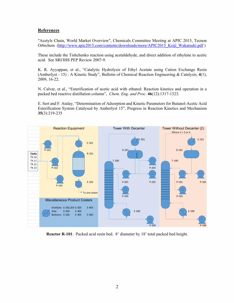
Background Ethyl and butyl acetates are solvents used in surface coatings, inks, flavorings and pharmaceuticals, and other applications. As they are not on EPA’s list of Hazardous Air Pollutants, they have displaced some listed compounds formerly used as solvents. Global demand is roughly 2.5 million metric tons of ethyl acetate and 1.8 million metric tons of butyl acetate[1]. They can be made from non-renewable or bio-sourced materials. Conventional technology to produce acetates is through the esterification of ethanol or butanol with acetic acid, using a heterogeneous or homogenous acid catalyst. The reaction is equilibrium limited, and the resulting acetates create multicomponent azeotropes with water and unreacted alcohols. Other routes to ethyl acetate have been commercialized[2], but conventional technology lends itself to using the same equipment for a variety of ester products. Project Scenario Your company makes commodity and specialty solvents, including ethyl and butyl acetates. They are looking to expand production capacity and are in negotiation to purchase the assets of a toll manufacturing facility believed to be suitable for these products. Strategically, the long term plan is to produce other specialty acetates, but the project needs to be justified on its ability to produce the ethyl and butyl acetates. Based on the equipment list provided by the toll manufacturer, you are asked to determine the production capacity for ethyl acetate and butyl acetate. An upper bound to what your company would pay is the cost to build a new grass roots unit of the same capacity. Also, determine the purchase cost such that the company would get a reasonable return on investment, assuming raw material margins of 5 to 20 cents per pound on making the acetates. (raw material margin = acetate selling price minus cost of contained raw materials) Kinetic information is available for ethyl acetate[3,4] and butyl acetate[5]. Once you determine the instantaneous (hourly) production rate, consider and discuss the campaign strategy to supply both acetates, with a sales ratio of 3:2 ethyl to butyl acetate. The toller advises that a complete turn-around is 18 hours. Shipments are spread evenly through the year plus or minus 20% on a weekly basis, and may be up to 20,000 gallons in a single rail shipment. Monte-Carlo simulations of demand schedules are helpful to determine the likelihood that shipments can be made with a given campaign strategy. Equipment Description Below is a sketch of the available equipment. Piping is quite flexible in that any tower can be fed from just about any point in the process. Available utilities include 75 psig steam, and cooling water is supplied at 90F and returned at 110F. For heat exchangers, you can use shortcut rating techniques with U=120 BTU/hr/ft2-F for reboilers, 100 for condensers, and 80 for coolers or heaters with no process phase change. Not shown is vacuum equipment such that each column can work independently under vacuum if needed. All columns are rated for normal operation up to 60 psig. The reactor is rated for 150 psig. You may not need to use all the available equipment. All equipment is 316L stainless steel.
2
References "Acetyls Chain, World Market Overview", Chemicals Committee Meeting at APIC 2015, Tecnon Orbichem (http://www.apic2015.com/contents/downloads/more/APIC2015_Keiji_Wakatsuki.pdf ) These include the Tishchenko reaction using acetaldehyde, and direct addition of ethylene to acetic acid. See SRI/IHS PEP Review 2007-9. K. R. Ayyappan, et al., “Catalytic Hydrolysis of Ethyl Acetate using Cation Exchange Resin (Amberlyst - 15) : A Kinetic Study”, Bulletin of Chemical Reaction Engineering & Catalysis, 4(1), 2009, 16-22. N. Calvar, et al., “Esterification of acetic acid with ethanol: Reaction kinetics and operation in a packed bed reactive distillation column”, Chem. Eng. and Proc. 46(12):1317-1323. E. Sert and F. Atalay, “Determination of Adsorption and Kinetic Parameters for Butanol-Acetic Acid Esterification System Catalysed by Amberlyst 15”, Progress in Reaction Kinetics and Mechanism 35(3):219-235
Reactor R-101: Packed acid resin bed. 8’ diameter by 18’ total packed bed height.
Where X = 3 or 4
E-201 E-X01E-101
P-101 D-201 D-X01Tanks R-101TK-10TK-11 T-200 T-X00TK-12TK-13 P-102 P-203
E-102 P-201 P-202 P-X01 P-X02P-103
To any towerP-205 P-X05
Distillate: E-202,203 E-303 E-403Side: E-204 E-304 E-200 E-X00Bottoms: E-205 E-305 E-405
P-200 P-X00
Tower Without Decanter (2)Tower With DecanterReaction Equipment
Miscellaneous Product Coolers

3
Column Diameter,
ft Trays Feed
(from top) Side Draw (from top)
T-200 7.5 45 Koch Flexitrays, 24” spacing, 2-pass
16, 20, 26, 30
5, 9
T-300 2.5 30 Kock Flexitrays, 24” spacing, single pass
10, 16, 20
5
T-400 6.0 30 Kock Flexitrays, 24” spacing, single pass
10, 14, 20
3
Reboiler Condenser Preheater Cooler ft2 ft2 ft2 ft2 R-100 E-101 500 E-102 700 T-200 E-200 5000 E-201 6500 E-202 1000
E-203 1000 E-204 800 E-205 700
T-300 E-300 800 E-301 1500 E-303 200 E-304 200 E-305 200
E-400 1500 E-401 2200 E-403 400 E-404 400 E-405 400
Pump Name Number gpm TDH,
ft Name Number gpm TDH,
ft Reactor Feed P-101
P-102 P-103
75 250
T-200 Bottoms P-200 75 200 T-200 Reflux P-201 300 100 Decanter Heavy Phase
P-202 250 150 Decanter Light Phase
P-203 250 150
T-200 Side P-205 75 150 T-300 Bottoms P-300 60 200 T-400 Bottoms P-400 50 200 T-300 Reflux P-301 25 150 T-400 Reflux P-401 250 150 T-300 Distillate P-302 30 200 T-400 Distillate P-402 200 200 T-300 Side P-305 30 200 T-400 Side P-405 30 200
Vessel Name Number Dia, ft Length,
ft Orientation Note
T-200 Decanter D-201 8 20 Horizontal T-300 Reflux Drum
D-301 3 8 Horizontal
T-400 Reflux Drum
D-401 6 16 Horizontal
Feed Tanks TK-10,11,12,13 40 40 Vertical Atmospheric

4
Test Tanks TK-20, 21 20 20 Vertical AtmosphericProduct Tanks TK-30, 31, 32,
33 65 40 Vertical Atmospheric
IBL Storage D-100, 101 12 36 Vertical 30 psig
5
2. Omega-3 Fatty Acids (recommended by Rick Bockrath, Consultant – formerly DuPont)
You work for a biotechnology company that has developed a heterotrophic microalgae capable of producing significant omega-3 fatty acid within the cell. Your company is interested in scaling this technology up to a commercial process for producing omega-3 fatty acids for dietary supplements. You are part of a team tasked to develop a plant design and economic estimates for a 400 metric tonne-per-year DHA facility based on patents and other technical literature. The DHA has two potential markets, nutritional supplement for infant formula and as fish larvae food in aqua farming.
Background
In the past 20 years, there has been an emergence of overwhelming evidence on the dietary significance of very long chain, polyunsaturated fatty acids (VL-PUFAs). In particular the omega-3 fatty acids, EPA (eicosapentaenoic acid, C20:5) and DHA (docosahexaenoic acid, C22:6), have wide-ranging benefits for improving heart health, immune function, mental health, and infant cognitive development.
Microorganisms, including microalgae, lower fungi, and marine bacteria are the primary producers of EPA and DHA. Fish usually obtain these VL-PUFAs via bioaccumulation in the food chain. Marine fish oil is presently the main source for the VL-PUFAs currently used for its commercial production. However, the recovery and purification of DHA and EPA from fish oils are expensive, and they typically have a "fishy" odor and after-taste. In addition, there are important concerns regarding contamination of fish oil with pesticides and heavy metals.
Annual EPA demand is about 125 tonnes in Japan alone. In 2000, the market price of EPA ethyl ester (95% pure) in bulk quantities was about $650/Kg. Sales from conventionally harvested fish products in 2012 were $ 1,500/tonne fish oil and $1,800/tonne for fishmeal. DuPont commercialized a fermentation-based route to EPA at that time. They developed yeast, Yarrowia lipolidica that could accumulate a large amount of EPA at high yield. Their product, New HarvestTM EPA went on sale in GNC stores in 2010. Similar products currently sell into the vegan nutritional supplement market at attractive prices. The FDA has rendered the opinion that DHA is a GRAS (generally regarded as safe) ingredient on its use as a supplement for infant formula. The value-in-use for infant formula nutritional supplements commands a premium price. Nevertheless, the process you design must compete favorably with the existing fish oil sourced and the DuPont product to compete in the fish larvae food market. It has been estimated that the market price in 2012 for high-purity bulk DHA is about $800/kg.
Fermentation for Lipid Accumulation
You have learned from your R&D team that significant lipid accumulation does not occur during active growth of the microbe as long as all nutrients are available in the fermentation broth. Once a nutrient other than the carbon source is depleted, usually the nitrogen source, the cell metabolism changes to accumulating lipid. Therefore, your fermentation process will progress in two stages. The first stage is the active growth phase during which the lipid content is modest, about 20% w/w dry cell mass. The second stage starts once the N-source is depleted and the C-source continues to be fed to the fermenter. The supplied C is converted into stored lipid within the microbe cell, rich in

6
DHA. Cell lipid at the end of this stage can constitute a large fraction of the total dry cell weight. To recover the DHA for purification you will need to design a process that can separate the lipid from the cells and purify it for your final product form.
Fermentation Operational Considerations
Sterility in the fermentation area will be a significant concern. Suitable measures must be taken to ensure that no adventitious organisms enter the process. This would introduce competition to your proprietary microbe, which would consume feedstock and generate undesired by-products. Everything entering the fermenter must be sterile, except of course for the inoculum.
Your proprietary organism is a genetically engineered microbe. Physical containment and control technology must, at a minimum, comply with the Toxic Substances Control Act (TSCA) Part 725.422. Facilities must be designed to physically contain the live organism. It is unlikely that the highly engineered organism could survive in the wild. Nevertheless, prior to removal from any containment, the organism must be deactivated or killed. Likewise, operating vents and spills that could contain live organism are to be contained and treated. The operating vent could be treated with a scrubber using a low concentration of bleach. Spills could be sent to a tank and processed if not contaminated with materials that could impact your downstream process.
Between fermentation batches, the fermenter is cleaned and sterilized to begin another batch. Your design may include multiple fermenters. You also need to provide laboratory facilities to grow the organism, inoculating each seed batch with a 1 mL vial in the lab containing 10 mg of live organism.
A common characteristic of all nutraceutical ingredients manufacture is that the products must be made to a high degree of purity and under very high sanitary conditions. Production equipment must be dedicated to nutraceutical ingredients and cannot be used for other industrial production. Plants producing nutraceuticals are subject to periodic inspection by the FDA.
Downstream Processing Alternatives
There are several methods to disrupt cells and extract the valuable lipid content. There may be trade-offs on which would work best for your processing situation. Once extracted, the DHA oil needs to be purified and refined like any other edible oil - using processes well known in the industry. Recall you will have two product forms, purified DHA for infant formula and disrupted biomass for fish feed. You will need to design downstream processing that can accommodate both product forms. You will also need to decide what product split optimizes the value for your business. An important consideration on process selection is the temperature and oxygen sensitive nature of LC-PUFAs. The unsaturation makes these compounds prone to autoxidation. It is important to keep temperatures low and the process vessels oxygen-free to avoid DHA degradation. Antioxidants, like tocopherols, are typically added to extend product shelf life. Your business director needs to know what combination purification technologies is economically preferred. You will need to develop a preliminary level flowsheet, investment estimate, cost of manufacture, and NPV for the alternatives to demonstrate which combination of isolation and purification technologies is preferred.
The plant design should be as environmentally friendly as possible. Recover and recycle process materials to the maximum economic extent. Also, energy consumption should be minimized, to the extent economically justified. The plant design must also be controllable and safe to operate.

7
Remember that you will be there for the start-up and will have to live with whatever design decisions you have made.
References
U.S. Patent 6,812,009 B2, Bladue et al., Nov. 2, 2004, “DHA-containing nutritional compositions and methods for their production”
U. S. Patent 9,249,434 B2, Behrens et al., Feb. 2, 2016, “Production of DHA in Microalgae in low pH medium”
Cohen, Z., Ratledge, C. (2010). Single Cell Oils - Microbial and Algal Oils, 2nd Ed. AOCS Press.
Xie, D., Jackson, E. N., Zhu, Q., Sustainable source of omega-3 eicosapentaenoic acid from metabolically engineered Yarrowia lipolytica: from fundamental research to commercial production, Appl. Microbiol Biotech. (2015) 99:1,599–1,610.
Bailey’s Industrial Oil and Fat Products, Sixth Edition, Six Volume Set. Edited by Fereidoon Shahidi. Copyright 2005, John Wiley & Sons, Inc.
Global Market Insights, "EPA/DHA (Omega 3) Ingredients Market Size By Application (Dietary Supplements, Pharmaceuticals, Functional Foods, Pet & Animal Feed, Infant Formulas), By Source (Anchovy/Sardine, High Concentrates, Medium Concentrates, Low Concentrates, Algae Oil, Tuna Oil, Cod Liver Oil, Salmon Oil, Krill Oil, Menhaden Oil), Industry Analysis Report, Regional Analysis, Application Potential, Price Trend, Competitive Market Share & Forecast, 2,015-2,022", March 2014

8
3. Direct Route to Phenol From Benzene (recommended by Bruce M. Vrana, DuPont) Phenol is a major chemical intermediate used in a variety of other products. Phenolic resins are used in a wide range of products, including printed circuit boards. Phenol is a raw material to make polycarbonate, used in CD, DVD and Blu-ray discs. Phenol can be converted to caprolactam and ultimately nylon-6, or to adipic acid and ultimately nylon-6,6, both used for fibers and engineering polymers. There are a wide variety of other applications for this versatile intermediate. Phenol is conventionally made from cumene using the following chemistry:
This route has several drawbacks. Growth in demand for propylene has exceeded the growth in supply, driving propylene prices higher. Also, one mole of acetone is made per mole of phenol. The acetone must be sold at a reasonable price in order to have favorable economics on making the phenol. Although acetone has numerous uses, phenol producers often have difficulty selling the byproduct at an attractive price. Effectively, this process converts high value propylene into low value acetone. In fact, although you could sell more phenol, your company has decided to not expand phenol capacity if it produces acetone as a coproduct. A team of scientists at the Council of Scientific and Industrial Research (CSIR) in New Delhi has recently patented a direct process from benzene to phenol. Their vapor-phase process uses air to oxidize benzene directly over a supported copper-chromium catalyst with about 95% yield at 28% conversion of benzene. Your company is considering licensing this technology. Your team has been assembled to determine whether the process will be economical before engaging in any discussions with CSIR. Because these negotiations can be sensitive, your management has forbidden any form of contact with anyone at CSIR during your design. You may use only information that you can find in the public domain, in the patent, on the Internet, etc. The objective is to obtain a license at the lowest possible price, so you do not want to tip off your company’s interest in the process until your engineering analysis is complete. Based on data in the patent, design the optimum process to make 500MM lb/yr of phenol from benzene at your plant complex on the U.S. Gulf Coast. You will need to focus on the process to make phenol, not the process to make the catalyst, which you can assume will be produced for you by a catalyst vendor. Benzene is available on site for $1,100/tonne. Phenol is worth $2,000/tonne to your company. All prices are forecasts by your marketing organization for long term average prices, expressed in 2017 dollars.
+ CH3 CH2
CH3 CH3
O OH
CH3 CH3
H+O2
OH
+
O
CH3 CH3
Cumene CHP (cumene
hydroperoxide)

9
You will need to make many assumptions to complete your design, since the data you have is far from complete. State them explicitly in your report, so that management may understand the uncertainty in your design and economic projections before approaching CSIR to discuss a license. Test your economics to reasonable ranges of your assumptions. If there are any possible “show-stoppers” (i.e., possible fatal flaws, if one assumption is incorrect that would make the design either technically infeasible or uneconomical), these need to be clearly communicated and understood before proceeding. The plant design should be as environmentally friendly as possible, at a minimum meeting Federal and state emissions regulations. Recover and recycle process materials to the maximum economic extent. Also, energy consumption should be minimized, to the extent economically justified. The plant design must also be controllable and safe to operate. Remember that if the negotiations are successful, you will be there for the plant start-up and will have to live with whatever design decisions you have made. Reference U. S. Patent 8,772,552, July 8, 2014, assigned to Council of Scientific and Industrial Research.
10
4. New Sorbent-Based CO2 Capture Method (recommended by Dr. Matthew Targett, LP Amina)
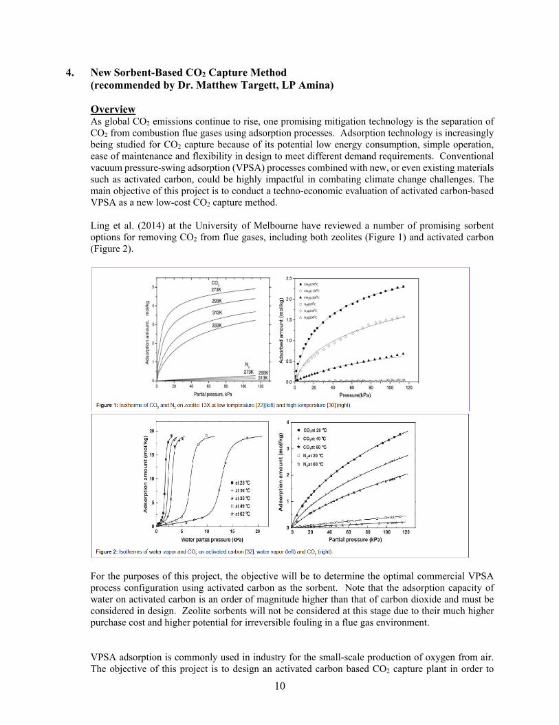
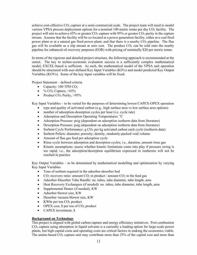
Overview As global CO2 emissions continue to rise, one promising mitigation technology is the separation of CO2 from combustion flue gases using adsorption processes. Adsorption technology is increasingly being studied for CO2 capture because of its potential low energy consumption, simple operation, ease of maintenance and flexibility in design to meet different demand requirements. Conventional vacuum pressure-swing adsorption (VPSA) processes combined with new, or even existing materials such as activated carbon, could be highly impactful in combating climate change challenges. The main objective of this project is to conduct a techno-economic evaluation of activated carbon-based VPSA as a new low-cost CO2 capture method. Ling et al. (2014) at the University of Melbourne have reviewed a number of promising sorbent options for removing CO2 from flue gases, including both zeolites (Figure 1) and activated carbon (Figure 2).
For the purposes of this project, the objective will be to determine the optimal commercial VPSA process configuration using activated carbon as the sorbent. Note that the adsorption capacity of water on activated carbon is an order of magnitude higher than that of carbon dioxide and must be considered in design. Zeolite sorbents will not be considered at this stage due to their much higher purchase cost and higher potential for irreversible fouling in a flue gas environment. VPSA adsorption is commonly used in industry for the small-scale production of oxygen from air. The objective of this project is to design an activated carbon based CO2 capture plant in order to
11
achieve cost-effective CO2 capture at a semi-commercial scale. The project team will need to model various VPSA process deployment options for a nominal 100 metric tonne per day CO2 facility. The project will aim to achieve 65% or greater CO2 capture with 95% or greater CO2 purity in the capture stream. Assume that the facility will be co-located at a power generation facility, either at a coal fired power plant or at a natural gas fired power plant; and that there is a nearby CO2 pipeline. The flue gas will be available as a slip stream at zero cost. The product CO2 can be sold onto the nearby pipeline for enhanced oil recovery purposes (EOR) with pricing of nominally $20 per metric tonne. In terms of the rigorous and detailed project structure, the following approach is recommended at the outset. The key to techno-economic evaluation success is a sufficiently complex mathematical model, EXCEL-based is sufficient. As such, the mathematical model of the VPSA unit operation should be structured with user-defined Key Input Variables (KIVs) and model predicted Key Output Variables (KOVs). Some of the key input variables will be fixed. Project Statement – defined criteria
Capacity: 100 TPD CO2 % CO2 Capture, >65% Product CO2 Purity, >95%
Key Input Variables – to be varied for the purposes of determining lowest CAPEX-OPEX operation
type and quality of activated carbon (e.g., high surface area vs low surface area options) number of adsorption-desorption cycles per hour (i.e. cycle rate) Adsorption and Desorption Operating Temperatures: oC Adsorption Pressure: psig (dependent on adsorption isotherm data from literature) Desorption Pressure: psig (dependent on adsorption isotherm data from literature) Sorbent Cycle Performance: g CO2 per kg activated carbon each cycle (isotherm data) Sorbent Pellets: diameter; porosity; density, randomly-packed void volume Amount of flue gas feed per adsorption cycle Rinse cycle between adsorption and desorption cycles; i.e., duration, amount rinse gas Kinetic assumptions: assess whether kinetic limitations come into play if pressure swing is
too rapid; i.e., the adsorption/desorption equilibrium expressed in isotherms will not be reached in practice
Key Output Variables – to be determined by mathematical modelling and optimization by varying Key Input Variables
Tons of sorbent required in the adsorber-desorber bed CO2 recovery ratio: amount CO2 in product / amount CO2 in the feed gas Adsorber-Desorber Tube Bundle: no. tubes, tube diameter, tube length, area Heat Recovery Exchangers (if needed): no. tubes, tube diameter, tube length, area Supplemental Heater (if needed), KW Adsorber blower size, KW Desorber vacuum blower size, KW KWhr per ton CO2 product OPEX cost, $ per ton of CO2 product CAPEX investment, $
Background on Technology This project is aligned with global carbon capture and energy efficiency initiatives. Post combustion CO2 capture using absorption in liquid solvents is a currently a leading option for large-scale power plants, but high capital costs and operating costs are critical factors in making the economics viable. The amine-based CO2 capture unit may contribute more than 25% of the capital cost and more than

12
50% of the power consumption of the host power plant. A more efficient, inexpensive means of carbon dioxide such as with activated carbon sorbents is desirable. Focus Areas for Commercialization Portion In your engineering assessments as well as economic and facility costs predictions, some aspects you will need to include are: Design:
- A notional design for sorbent reactors appropriate for 100 TPD production target, with particular attention in the design to preventing excessive heat buildup due to the highly exothermic adsorption process.
- The role of water in flue gas and its effect on CO2 adsorption-desorption; and the NEED to consider a two-stage process; i.e., water removal followed by CO2 removal
- Consideration of activated carbon sorbent degradation - Auxiliary equipment requirements for your plant - A brief exploration of the integration of the 100 ton/day facility into a coal fired or natural gas fired
plant. Costing:
- Location of facility is next to power generation unit and a CO2 pipeline - Price projections for electricity to power your adsorber-desorber-rinse blowers - Fixed and variable costs (e.g., CAPEX, OPEX) - Return on investment in the form of expected Investor’s Rate of Return (IRR) for the given CO2 sale
price and quantity, assuming price increases at the same rate per year as inflation (assume yearly inflation level appropriate for plant location)
- Carbon credits/taxes and potential impact on project economics In judging the competitiveness of your plant design in a given location, you should take into account the political and economic landscape of the energy industry and the impact of climate change regulations. Also, take into account the changing nature of energy policy, such as incentives for construction of low-carbon power plants and other regulations that may give you an upper hand (carbon credits, cap and trade, etc.).
Note: The creator of this project is not based in Philadelphia. Many or all interactions will be through SKYPE, phone, and/or email.
References Ling, JH; Ntiamoah, A; Xiao, P; Xu, D; Webley, PA; Zhai, YC; Overview of CO2 Capture from Flue Gas Streams by Vacuum Pressure Swing Adsorption Technology. Austin Chem. Eng. 2014; 1(2): 1009. Zhang, J; Webley, PA; Cycle Development and Design for CO2 Capture from Flue Gas by Vacuum Swing Adsorption. Environ. Sci. Technol. 2008; 42: 563-569. Zhang, J; Xiao, P; Li, G; Webley, PA; Effect of Flue Gas Impurities on CO2 Capture Performance from Flue Gas at Coal-fired Power Stations by Vacuum Swing Adsorption. Energy Procedia. 2009; 1: 1115-1122. Ruiz, E; Sanchez, JM; Marono, M; Otero, J; CO2 capture from PCC power plants using solid sorbents: Bench scale study on synthetic gas. Fuel. 2013; 114: 143-152.

13
Li, G; Xiao, P; Zhang, J; Webley, PA; Xu, D; The role of water on post combustion CO2 capture by vacuum swing adsorption: Bed layering and purge to feed ratio. AIChE J. 2014; 60: 673-689. Xu, D; Xiao, P; Li, G; Zhang, J; Webley, PA; Zhai, Y; CO2 Capture by Vacuum Swing Adsorption Using F200 and Sorbead WS as Protective Pre-layers. Chin. J Chem. Eng. 2012; 20: 849-855. Xu, D; Guo, H; Liu, HQ; Zhang, J; Xiao, P; CO2 and H2O Capture from High Humidity Flue Gas by Single Multi-Layer Vacuum Swing Adsorption Unit. Adv. Mater. Res. 2012; 529: 402-407. Agarwal, A; Biegler, LT; Zitney, SE; A superstructure-based optimal synthesis of PSA cycles for post-combustion CO2 capture. AIChE J. 2010; 56: 1813-1828. Liu, Z; Wang, L; Kong, X; Li, P; Yu, J; Rodrigues, AE; Onsite CO2 Capture from Flue Gas by an Adsorption Process in a Coal-Fired Power Plant. Ind. Eng. Chem. Res. 2012; 51: 7355-7363. Shen, C; Liu, Z; Li, P; Yu, J; Two-Stage VPSA Process for CO2 Capture from Flue Gas Using Activated Carbon Beads. Ind. Eng. Chem. Res. 2012; 51: 5011-5021. Smith, OJ; Westerberg, AW; Carnegie Mellon Univ. Eng. Des. Res. Cen.; and AIChE Meeting: Chicago, Ill, "The optimal design of pressure swing adsorption systems" (1990). Dept. Chem. Eng. Paper 173. Waldron, WE, Sircar, S. (2000). Parametric Study of a Pressure Swing Adsorption Process. Adsorption, 6, 179-188. Knaebel, KS. (n.d.). "How To" Guide for Adsorber Design. Dublin, OH: Adsorption Research, Inc. Warren, ML, Julian, SC, Peter, H. (2005). Chapter 25. Adsorption and Fixed-Bed Separations: Vol. 836-880. Unit Oper. Chem. Eng. (7th ed.). Boston, MA: McGraw-Hill.

14
5. Sodium and Specialty Cyanides Production Facility (recommended by Stephen M. Tieri, DuPont) Sodium cyanide and specialty cyanides are commercially valuable materials used in wide variety of applications and industries; including electroplating, mining and metal processing, and organic chemicals production. Sodium cyanide is used throughout the world and is instrumental in the extraction of gold, silver, and other precious metals naturally occurring in low concentrations in ore. As a chemical intermediate, it provides a supply of hydrogen cyanide in regions where a local supply is not available, since sodium cyanide can be transported and stored. Driven by the current and forecasted growth in precious metals, consumer electronics, and electronics materials, the global sodium cyanide demand is expected to grow by 4-percent annually, with a forecasted global demand of 1.1 million tonnes in 2018. While there have been initiatives to substitute sodium cyanide in gold recovery because of potential environmental danger if not handled responsibly, it remains the most environment-friendly of the possible substitutes. For this project, your company’s business team identified and is negotiating an agreement for a manufacturing site in Rochester, Nevada. This partner site location is a currently undeveloped section of an existing manufacturing site, with access to natural gas and electricity, but with limited aqueous waste treatment. The site host company is a medium sized gold/silver ore mining and recovery company, interested in an on-site partner for future capacity expansion. Sodium cyanide is typically produced by the neutralization of hydrocyanic acid with aqueous sodium hydroxide. Water is evaporated from the aqueous solution to generate solid product. HCN + NaOH NaCN + H2O (1)
Dry NaCN solids are then compacted into briquettes prior to loading into their final shipping container. Specialty cyanides (KCN, LiCN, etc.) are produced using similar chemistry, but with their respective cation caustic solutions in place of NaOH. There are several options for commercial production of hydrogen cyanide (HCN). However, for this location and capacity requirement, HCN is expected to be generated on-site, produced directly by either the Andrussow or Degussa process. While both react ammonia and methane over a precious metal catalyst, oxygen is present in the Andrussow process reaction (2) and excluded in the Degussa process reaction (3). Additionally, there are different impurity profiles generated by the two processes.
CH4 + NH3 + 1.5 O2 HCN + 3 H2O (2) CH4 + NH3 HCN + 3 H2 (3)
Your project team has been assembled to design this new cyanides production facility using the best commercially demonstrated, sustainable, and economically viable technology. The business objective is to deliver a commercial scale facility with the capacity to produce 60 K Tonnes/yr (60,000 MT/yr, 60 MM Kg/yr) of sodium cyanide (NaCN) and 2 K Tonnes/yr (2,000 MT/yr, 2 MM Kg/yr) of total specialty cyanides (KCN, LiCN, CaCN). Your team is also responsible for identifying and minimizing the required investment and operating costs, and identifying any critical economic sensitivities to raw materials, product, utility, or equipment pricing, use quantity, and quality. The product quality and purity should meet or exceed current industry expectations, 98% ±1% product as solid briquettes or as a 10-25 wt% solution of NaCN in water. All solution product must

15
be used/consumed onsite, with a maximum of 15% total solution sales (dry cyanide basis). Sodium cyanide product price is expected to in the range of $1.80-$2.00, and fluctuate with demand and gold pricing. Natural gas is available onsite at market price and at average US composition. The team is expected to identify whether additional purification of the natural gas feed is necessary prior to use, depending on the resulting product quality, investment, and cost impacts. Ammonia, NaOH, and other alkali metal hydroxides are available at market prices. The facility should have the capability to ship briquettes in rail cars, ISO containers, hopper trailers, and 1 tonne bags/supersacks. Any unconverted ammonia is expected to be thermally treated, recovered, or converted to a co-product to minimize air emissions. While sodium and specialty cyanides provide meaningful benefits to society, they have the potential for harm if not managed properly. Cyanide is acutely toxic to humans. Liquid or gaseous hydrogen cyanide and alkali salts of cyanide can enter the body through inhalation, ingestion or absorption through the eyes and skin. The toxicity of these materials represent a potential environmental or health hazard if the product is not used, transported, and handled correctly. The process, systems, and equipment will need to minimize the potential for material contact with personnel and the environment, including safety systems with extensive alarm and monitoring systems designed to detect, mitigate, and contain an HCN release. The plant design should be as environmentally friendly as possible, and as state and federal emissions legislation require. It is expected that the facility will include emission control equipment as a part of the process design and operation. Recover and recycle process materials to the maximum economic extent. Also, energy consumption should be minimized, to the extent economically justified. The plant design must also be controllable and safe to operate. As the process technology integration and design team, you will be there for the start-up and will have to live with whatever design decisions you have made. Undoubtedly, you will need additional data beyond that given here and obtained from the references below. Cite any literature data used. If required, make reasonable assumptions, state them, and identify whether your design or economics are sensitive to the assumptions you have made.
References 1. Int’l. Cyanide Management Code For the Manufacture, Transport, and Use of Cyanide In the
Production of Gold, www.cyanidecode.org 2. Assuring Process Safety in the Transfer of Hydrogen Cyanide Manufacturing Technology;
Maxwell, G. R. et al.; J. Hazard. Mat’ls., 142, 3, 11 April 2007, 677–684. 3. US Patent 2006981, Andrussow, L.; “Production of hydrocyanic acid” to IG Farbenindustrie;
Sep. 02, 1935. 4. US Patent 2105831, Andrussow, L.; “Production of hydrocyanic acid” to IG Farbenindustrie;
Jan. 18, 1938. 5. US Patent 2011171101, Schaefer, T., et al.; “Reactor for preparing hydrogen cyanide by the
Andrussow process” to Evonik Roehm GmbH; July 14, 2011. 6. US Patent 4961914, Witzel, M.. et al.; “Method of preparing hydrogen cyanide” to Degussa;
Oct 09, 1990. 7. www.ams.usda.gov 8. http://www.eia.gov/forecasts/steo/ 9. Conceptual Design of Chemical Processes; Douglas, J.M.; McGraw-Hill; 1988 10. Flow of Fluids Through Valves, Fittings, and Pipe – Technical Paper No. 410; Crane Co.; 1988. 11. ECN Phyllis Database for Biomass and Waste - https://www.ecn.nl/phyllis2/ 12. Pirie, J. M., “The manufacture of hydrocyanic acid by the Andrussow process,” Plat. Metals
Rev., 2, 1, 7-11; 1958.

16
6. Coffee to Biofuels (recommended by Stephen M. Tieri, DuPont) Millions across the world enjoy a cup of coffee to start the day, as an energy boost to keep going, and/or as an after dinner refreshment. As a consumable product, it maintains a unique position and importance in global cuisine, culture, trade, sustainability, social ethics, and economics. It is the second most traded commodity in the world (first is oil), with health benefits including a 10% increase in metabolism and a 65% reduction in potential to develop Alzheimer’s disease. Coffee beverages can be produced using dozens of different techniques that stem from every corner of the globe. Most all require the mixing of ground coffee with hot water, followed by a removal of the coffee grinds prior to drinking. But what is the ultimate fate of the spent coffee grinds – into the trash, then on to the landfill? – possibly saved and added to the compost pile? Can this coffee waste power cars, buses, buildings, and cities? A new startup company has developed process technology that converts waste coffee grinds into advanced biofuels and potentially biochemicals. Their new technology recycles the coffee grinds into carbon-neutral advanced biofuels, biodiesel and biomass pellets; has already won several environmental and “green” awards; and has captivated the marketing teams from numerous large international companies. By reinvesting the financial portions of the prizes, the startup is currently demonstrating the integrated process and technology at a pilot-scale facility. For the small-scale demonstration, the plant is supplied with waste coffee grinds collected locally from the London area. Following this success, the startup is looking to partner with existing industry to expand internationally in both Europe and the United States. Additionally, coffee waste as a biofuel feed stock has a number of advantages over typical biofuel feed materials. As a waste material, it doesn’t compete with food crops, which is a typical issue for first-generation biofuels made from corn or palm oil. From a process standpoint, feedstock filtration is not required, as it is for the used/waste cooking oils used as biofuel feed materials. Overall, the startup company’s technology integrates previously independent oil extraction, biodiesel conversion, and biomass solid fuel production technologies. More specifically, oils from the coffee grinds are extracted for conversion to biodiesel, with the remaining solids from coffee grind waste converted into burnable pellets for boilers and stoves. Currently marketing information from the startup company describes the process as having the capability to convert 1 tonne (1,000 Kg) waste coffee grinds into 200 liters of fuel; based on waste coffee grinds with an estimated oil content of 15-20 wt% oil. The remaining 80-85 wt% is advertised as available for conversion into bio-mass pellets. Additionally, the process as currently practiced by the startup includes an initial drying step for the feed coffee grinds prior to the extraction steps. However, your company’s business and technology directors recognize that there are several factors having significant influence on overall conversion values, among them raw material moisture and any other pre-extraction/front-end processing steps, extractant use and recycle, and associated process equipment and unit-operation efficiencies. Your company is interested in partnering with this startup to design, construct, and operate the first generation of commercial coffee-to-fuel facilities. The joint business teams are planning an aggressive expansion to quickly capture public interest and market value. The growth-based objectives are focused on construction and operation of four facilities, each with the capability to process 200 K tonnes/yr (200,000 MT/yr, 200 MMKg/yr) of waste coffee grind and produce a minimum of 40 MM L/yr of biodiesel. The plans begins with a new a new larger London facility in the first year, with international expansion to Rome, Milan, and New York City in the second year.
Your team has been assembled to provide an independent evaluation of the technology and estimates of the potential investment and expected operating costs. The investment and manufacturing cost

17
estimates are key to validating the initial economic profit estimates and as input into final negotiations with the startup company partner. For the first generation of Waste Coffee to Energy facilities the desired products are liquid and solid advanced biofuels; specifically biodiesel, biomass pellets, and/or biomass briquettes. Current market pricing is to be expected for all raw materials, utilities, and biodiesel, and solid-fuel products, at each specified production location. Annual revenue and profitability must be evaluated both with and without Renewable Energy Credits. While the directors have no specific restrictions for facility location, the locations should be within 50 miles of the target cities, to be reasonably close to minimize collection and transportation costs. It is expected that waste coffee grounds would be supplied by truck, collected from the target cities themselves and the surrounding suburbs. Waste coffee grind collection is a necessary step in the overall business plan, but outside of the technology and engineering scope for facility design. Your company plans to partner with existing third-party, waste-collection providers to source the waste coffee grinds, which eliminates the need for collection vehicles and labor and potential competition issues with waste contractors. Include reasonable collection costs (and revenue if possible) in the overall economic analysis (including a shared/allocated portion of labor, fuel, vehicle investment and maintenance) and identify the impact on and sensitivity on the financial viability and sustainability of this new advanced biofuel technology. However, from a process engineering design and technology standpoint, the process boundaries are from collected grounds delivered by truck to the manufacturing facility gate through conversion to liquid and solid fuel products (including to short-term, on-site storage). As the facilities potential products are intended as transportation and residential fuels, it is essential that the process be as energy efficient as possible. Your team is expected to identify potential process upgrades and include them in the design to the extent they are economically attractive. While the technology and business directors are concerned about the investment and cost associated with drying the feed grinds, there are downstream steps and unit operations with the potential for significant impact on energy use and utility costs. This technology has potential use worldwide, including regions where water for industrial use is an extremely limited resource, which is a concern for any potential plant site. Therefore, the plant and process design will need to use the minimum amount of water necessary for the technology, and with the goal of being a zero-discharge plant, meaning that all process water is recycled within the plant. A biofuel benchmark for total water use is a fuel ethanol plant, typically using about 3 gal water/gal of product, which the design should strive to meet or exceed. The plant design should be as environmentally friendly as possible, and as required by state and federal emissions legislation. It is expected that the facility will include emission control equipment as a part of the process design and operation. Recover and recycle process materials to the maximum economic extent. Also, energy consumption should be minimized, to the extent economically justified. The plant design must also be controllable and safe to operate. As the process technology integration and design team, you will be there for the start-up and will have to live with whatever design decisions you have made. You will need additional data beyond that given here and listed in the references below. Cite any literature data used. If required, make reasonable assumptions, state them, and identify whether your design or economics are sensitive to the assumptions you have made.

18
References 1. http://www.cnn.com/2016/07/08/world/coffee-recycling-bio-bean/ 2. Bio-Bean - http://www.bio-bean.com/ 3. Methods, systems, and apparatus for obtaining biofuel from coffee and fuels produced therefrom;
Misra et al., US Patent 8591605 B2 http://www.google.com/patents/US8591605 4. Wake Up and Smell the Coffee Biodiesel, S. R. Schill, Biodiesel Magazine, February 10, 2009
- http://biodieselmagazine.com/articles/3238/wake-up-and-smell-the-coffee-biodiesel/ 5. A Renewable Fuel Using Coffee Grounds and Method for Manufacturing Thereof; K. Y. Se -
KR20100112802 (A) ― 2010-10-20 6. Pellets and Briquettes from Compacted Biomass; Myers et al.; US Patent Application
20150128487, May 14, 2015. 7. Oil extracted from spent coffee grounds as a renewable source for fatty-acid methyl-ester
manufacturing, Al-Hamamre et al.; Fuel, 96, June 2012, 70–76 – 8. http://www.sciencedirect.com/science/article/pii/S0016236112000464 9. Spent Coffee Grounds as a Versatile Source of Green Energy; Kondamudi et al.; J.Agricult. and
Food Chem., 2008, 56, 11757–11760. 10. Valorization of Coffee Grounds for Biodiesel Production; Caetano et al.; Chem. Eng. Trans.,
AIDIC; 26, 2012 - www.aidic.it/cet/12/26/045.pdf 11. http://www.eia.gov/forecasts/steo/ 12. Conceptual Design of Chemical Processes; Douglas, J.M.; McGraw-Hill; 1988 13. Flow of Fluids Through Valves, Fittings, and Pipe – Technical Paper No. 410; Crane Co.; 1988 14. ECN Phyllis Database for Biomass and Waste - https://www.ecn.nl/phyllis2/ 15. www.ams.usda.gov 16. National Coffee Association USA - http://www.ncausa.org/ 17. International Coffee Organization - http://www.ico.org/ 18. Assuring Process Safety in the Transfer of Hydrogen Cyanide Manufacturing Technology; Maxwell, G.
R., et al.; J. Hazard. Mat’ls.; 142, 3, 11 April 2007, 677–684. 19. Simultaneous coffee hydrolysis and oil extraction; Gottesman, M.; US Patent 4544567; October 1, 1985

19
7. Bioprocessing with Brewer’s Spent Grain (recommended by Scott L. Diamond, UPenn)
With the increase of microbreweries in urban areas, brewer’s spent grain (BSG) has the opportunity to be a low cost feed stream for bioprocessing. When produced in rural areas, wet BSG can be fed to farm animals. However, transportation costs and scalability issues may limit the use of urban BSG as animal feed. Assuming annual collection of freely available BSG from 10 microbreweries producing 15,000 barrels per year, 3 breweries producing 40,000 barrels, and 1 brewery producing 150,000 barrels, calculate minimal transportation costs within a 50-mile radius. Establish a fermentation schedule to produce two products: (1) a high purity bioproduct (xylitol or polylactic acid), and (2) a high quality biofuel (ethanol), ideally by continuous processing, using BSG as the major feedstock. Determine prevailing market conditions that dictate the bioproduct/biofuel ratio of production in a given year. Evaluate the sensitivity of the overall economic viability to the prevailing price of oil (ranging from $50 to 150/barrel). References Many publications on BSG and bioprocessing to ethanol, xylitol and polylactic acid available. Note: Good chance to use batch data to design a continuous process.
20
8. Polyether Synthesis (recommended by P. C. Gopalratnam, Consultant – formerly DuPont, Invista)
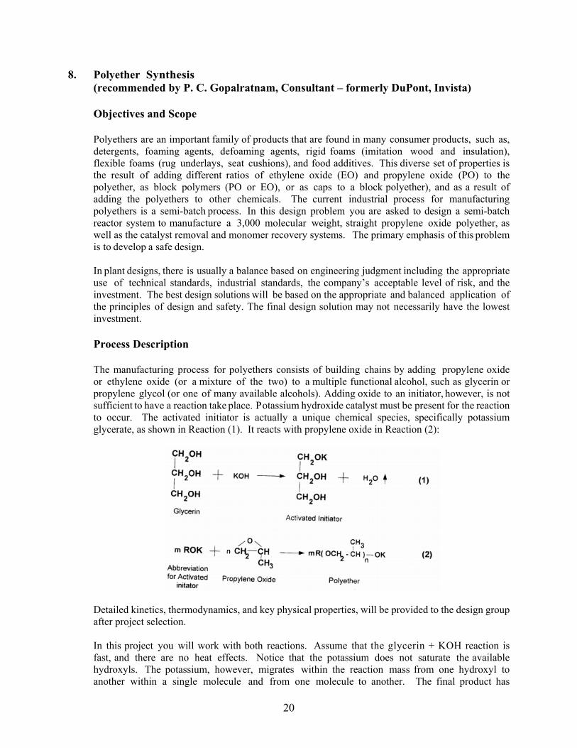
Objectives and Scope Polyethers are an important family of products that are found in many consumer products, such as, detergents, foaming agents, defoaming agents, rigid foams (imitation wood and insulation), flexible foams (rug underlays, seat cushions), and food additives. This diverse set of properties is the result of adding different ratios of ethylene oxide (EO) and propylene oxide (PO) to the polyether, as block polymers (PO or EO), or as caps to a block polyether), and as a result of adding the polyethers to other chemicals. The current industrial process for manufacturing polyethers is a semi-batch process. In this design problem you are asked to design a semi-batch reactor system to manufacture a 3,000 molecular weight, straight propylene oxide polyether, as well as the catalyst removal and monomer recovery systems. The primary emphasis of this problem is to develop a safe design. In plant designs, there is usually a balance based on engineering judgment including the appropriate use of technical standards, industrial standards, the company’s acceptable level of risk, and the investment. The best design solutions will be based on the appropriate and balanced application of the principles of design and safety. The final design solution may not necessarily have the lowest investment. Process Description The manufacturing process for polyethers consists of building chains by adding propylene oxide or ethylene oxide (or a mixture of the two) to a multiple functional alcohol, such as glycerin or propylene glycol (or one of many available alcohols). Adding oxide to an initiator, however, is not sufficient to have a reaction take place. Potassium hydroxide catalyst must be present for the reaction to occur. The activated initiator is actually a unique chemical species, specifically potassium glycerate, as shown in Reaction (1). It reacts with propylene oxide in Reaction (2):
Detailed kinetics, thermodynamics, and key physical properties, will be provided to the design group after project selection. In this project you will work with both reactions. Assume that the glycerin + KOH reaction is fast, and there are no heat effects. Notice that the potassium does not saturate the available hydroxyls. The potassium, however, migrates within the reaction mass from one hydroxyl to another within a single molecule and from one molecule to another. The final product has

21
approximately equal length chains on each molecule. The molecular weight of a typical polyether may range from a few hundred to thousands. The reactor of this project will manufacture a 3,000 molecular weight polyether. Your design should facilitate a six-step reaction process: 1) add glycerin to the reactor and then add the potassium hydroxide catalyst (3 wt% KOH or 0.03 × [lb glycerin + lb KOH]) to the reactor, 2) heat the mass to the reaction temperature, 3) remove the water down to 0.5 wt% water by vacuum stripping to form the activated initiator (the water is removed in accordance with the vapor pressure of water over the mass; assume the partial pressure is equal to the weight fraction times the vapor pressure), 4) add the propylene oxide, remove the heat of the exothermic reaction to control the temperature, and continue the addition to form the 3,000 molec. wt. product, 5) at the end of the addition period, react the free oxide down to 1%, and 6) transfer the hot product to the next process step for catalyst removal and the addition of an oxygen inhibitor package. Downstream of the reactor, you will need to add an antioxidant to prevent further polymerization. You also need to remove the catalyst to meet product purity specs. Any residual unconverted feedstock in the product needs to be removed in a stripping column. The impure feedstock can be recycled back to the PO/EO plant for purification. Design Project Specifications Capacity: Manufacture 100 million pounds per year of a 3,000 molec. wt. polyether that is made with glycerin, a potassium hydroxide catalyst (3 wt% potassium hydroxide) and propylene oxide. Chemistry: Start with glycerin, catalyst, and propylene oxide. All of the KOH reacts with the glycerol, which is highly exothermic. As a design basis, the KOH is limited to 3 wt% because it may precipitate as a solid when the concentration exceeds approximately this 3 wt% limit. Reactor Configuration: You will need to design heating and cooling systems to heat the reaction mass up to temperature, evaporate the water and remove the heat of reaction. Keep in mind that the heating and cooling capacity may impact the cycle time of the reactor and thus impact the plant capacity. Assume the oxide comes from an existing storage vessel. In your design, you will need to provide a pump and the controls to appropriately add the oxide into the reactor, and to control the temperature. Your design may have more than one reactor. Utilities: Assume that the following utilities are available at any capacity; i.e., water at 75°F, steam at 125 psig, electrical power, instrument air at 85 psig and nitrogen at 85 psig. Process Conditions and Constraints: Control the maximum temperature of the reaction at or below 260°F (it is known that the product degrades at or above this temperature). If the temperature is too low (say lower than 212F) then the reaction rate is very low, and the free oxide will increase to prohibitively high concentrations. Use stainless steel to prevent contamination. Transfer the product to the catalyst removal station at the reaction temperature after you react the free oxide down to 1 wt%. Basis for Investments: Determine the total investment based on the cost of the major equipment, including: vessels, heat exchangers, controls (or control loops), pumps, vacuum system, relief valves, and catch tanks.
22
Specific Deliverables of this Design Project 1. Determine the best design for this reactor system: a) determine the capital investment for
a semi-batch polyether reactor system, and b) include and emphasize the appropriate use of design and safety features.
2. Size the safety relief valves for the reactor or reactors and only for the runaway reaction scenario.
3. Consider the options of using recycle glycerol or purchasing virgin supply in your design. Provide economic justifications for these alternatives. Remember recycle streams will have to be “cleaned up” to remove impurities and unwanted components.
4. Include details for catalyst removal from the system and the subsequent disposal options with corresponding costs.
5. Include a simple addition system for the inhibitor to the final product with technical specifications.
6. Include a stripping column to remove residual propylene and ethylene oxide. 7. Since forecasting customer demand is an imprecise art, provide options to make a range
of molec. wt. of this product with corresponding sizing of pumps and other equipment. Determine if there is any impact on plant capacity.
8. Conduct and document a safety review that contains two parts: a) Hazards: a clear description of the major hazards of this process and what design features are incorporated to circumvent these hazards, and b) Inherent Safety highlights of one or more of the following inherent safety concepts: i) design features for easier and effective maintain-ability, and ii) design features using inherent safety concepts that circumvent accidents even when instruments fail or operators make mistakes.
9. Develop recommendations for the best design and state your reasons for these recommendations.
10. Provide a list of all equipment used in the process, including type, description, function, materials of construction, size, operating conditions, purchase and installed costs, and all important specifications
Appendices A1 A detailed investment analysis appears in the body of your design report. This appendix
includes spreadsheet calculations showing formulas, sample calculations, and sources of the methods used.
A2 Safety Review- Enclose the MSDSs to this Appendix A2. A3 Computer Process Simulators and Other Programs - Use generally available process
simulators (ASPEN PLUS®, etc.) together with spreadsheets and student-developed computer programs. Include a description of when and where each simulation package was used, and the important input and output sheets. Relate this information (using the appropriate labels) to the PFD or the P&ID.
A4 Back-up/Support Data and Calculations - Provide documentation for the calculations made by hand at least on a sample basis, but preferably include all hand calculations made for the design. Include flow charts where possible. All special-purpose computer programs must be documented by including a brief description, input, and output files. This means that cell formulas must be included for your spreadsheet calculations.

23
References
1. Seider, W. D., et al.; Product and Process Design Principles: Synthesis, Analysis and
Evaluation, 4th Edition 2. Fauske, H. K., “Generalized Vent Sizing Monogram for Runaway Reactions,” Plant
Operations Prog., 3, 4, 1984. 3. Grassel, S. S., “Design and Sizing of Knockout Drums/Catchtanks for Reactor Emergency
Relief Systems,” Plant Operations Prog., July 1986.

24
9. Low-cost production of a Hepatitis-C drug: the nucleotide analog Sovaldi (Sofosbuvir) (Recommended by John C. Crocker, UPenn)
Roughly 2-3% of the global population is chronically infected with the Hepatitis-C virus (HCV), and roughly 350,000 people die every year due to HCV-related illnesses, notably liver cirrhosis and cancer [1]. In 2013, biotech startup Gilead Sciences announced a new therapy that could cure 99% of patients suffering from the most common strain of HCV with a simple 12 week course of oral-administered drugs, with low incidence of side effects [2]. The therapy consists of a combination of two compounds Harvoni (Ledipasvir) and Sovaldi (Sofosbuvir), both of which work by inhibiting the reverse transcription enzyme NS5B required for the retrovirus HCV to replicate [3]. The excitement around this announcement was tempered by the cost of the cure [4], roughly $100,000 per patient; (i.e. treating the ~200 million people with HCV would cost $20 trillion). Of the two compounds, the second (Sofosbuvir) is the more complex to synthesize and purify due to its containing a chiral quaternary center with F/Me. Subsequent studies have shown that the first compound (Ledipasvir) is not required: Sofosbuvir in combination with an existing generic anti-retroviral compound Ribavirin [5] is also highly effective against HCV [6,7]. While its patent does not expire until 2029, in 2015 Gilead extended a low-cost license to pharmaceutical manufacturer Mylan NV to produce low-cost Sofosbuvir in India [8]. Sofosbuvir is a fluorinated analog of uridine monophosphate nucleotide, UMP, Figure 1. The compound is an inactive prodrug, which is intracellularly phosphorylated to the triphosphate active antiviral agent (analogous to uridine triphosphate UTP). The active agent is believed to act as a defective substrate for DNA reverse polymerization: after incorporation into the growing chain, the 2’ methyl group prevents the binding of the incoming nucleotide NTP, terminating chain growth. The favorable potency of the Sofosbuvir compound is due to its monophosphate and leaving groups, similar compounds without them have shown the first phosphorylation step to be both slow and rate limiting, resulting in low levels of the active antiviral in the cytosol [3]. This project is to design a production facility that will produce the compound Sofosbuvir generically, in a quantity sufficient to treat 10M patients per year, at a minimal cost per dose. Existing minimal production cost estimates for Sofosbuvir come in at ~$3/g or $100 for a 12 week, 35g course of therapy [9], establishing a benchmark for the team to attain. The team is expected to thoroughly review the process patent literature [10-13] for this compound to determine the different synthetic approaches currently in use, and will then proceed to design a plant around one of these processes that they deem likely to be least costly. Estimates for other processes (straw designs) may be evaluated to verify the cost effectiveness of the approach. Students are welcome to devise their own innovative approaches to process steps to minimize cost. Production is expected to be batch or semi-batch, and sized to produce the full annual output in 6 calendar months of production, while concentrating labor in a single 5 weekday, 40 hr/wk shift. Specialized equipment will have to be sourced, quoted and factored into the compound cost, as well as the cost of labor. Standard equipment, waste disposal, utilities and the workspace itself will be assumed to be available in a generic production facility at a small, estimated marginal costs. Licensing fees to Gilead or other patent holders will not be considered here; production will be assumed to be overseas with a zero-cost license, in a low or middle income country, analogous to the Mylan NV license. A financial model will be developed to determine a treatment price (above cost) to generate a positive or neutral NPV
Figure 1: Structure of Sofosbuvir, a fluorinated analog of uridine monophosphate (UMP) nucleotide.

25
after 5 or 10 years of production with a suitable discount rate and estimated costs of compound formulation, packaging, inventory, Ribavirin, etc. References 1. Clin Infect Dis. 2012 Jul;55 Suppl 1:S10-5. doi: 10.1093/cid/cis361 2. http://www.natap.org/2013/CROI/croi_07.htm 3. https://en.wikipedia.org/wiki/Sofosbuvir 4. http://www.nejm.org/doi/full/10.1056/NEJMe1401508 5. https://en.wikipedia.org/wiki/Ribavirin 6. http://pag.ias2013.org/abstracts.aspx?aid=3142 7. http://www.who.int/phi/implementation/ip_trade/sofosbuvir_report_updated.pdf 8. http://www.xraymachines.info/article/804153469/sofosbuvir-new-patent-wo-2015097605-
mylan/ 9. http://pag.ias2013.org/EPosterHandler.axd?aid=3142 10. https://www.google.com/patents/WO2011123668A2?cl=en 11. https://www.google.com/patents/WO2011123645A2?cl=en 12. https://www.google.com/patents/WO2012012465A1?cl=en 13. https://www.google.com/patents/WO2015097605A1?cl=en

26
10. Efficient Cooking Stove for Developing Countries – Product Design (Recommended by Adam A. Brostow, LNG Process Technology, Air Products and Chemicals, Inc.) Background I’m a member of Engineers Without Borders, Philadelphia Professional Chapter. I co-lead a clean water project in Las Delicias, El Salvador, a village of 3,000. Most of the village has no electricity. For cooking they use wood, charcoal, and propane. 50% of households use gas only, 20% wood/charcoal and gas (stove stacking), and 30% wood only. They have to pay for all three. For example, a bunch of wood, 30’’x40’’x7’ costs $30 (GRP per capita is $3,800, largely earned by the educated elite).
Figure 1
Figure 1 shows a typical kitchen in Las Delicias and people carrying wood.
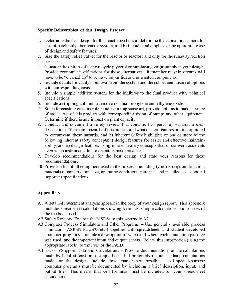
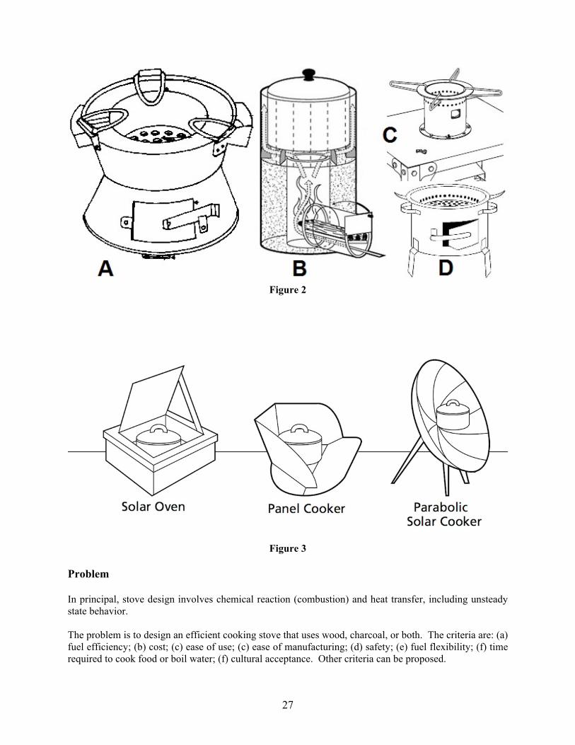
There are multiple issues with using wood/charcoal. The houses are filled with smoke that makes children sick. Gathering/carrying wood is a burden, especially for women. Using wood for fuel causes deforestation which, in turn, triggers floods during the rainy season. Finally, cost of all fuels is significant. Drinking water gets contaminated in storage. Boiling water for consumption is one way to kill all pathogens. Figure 2 shows example efficient stoves. A is a Kenya Ceramic Jiko stove. It burns charcoal and reduces fuel consumption by 20–50%. B is a Rocket Stove. It reduces fuel consumption by up to 50%. C is a Turbococina, Salvadoran patented design funded by NASA. It’s very efficient, but it requires electricity to fan the air to aid combustion. D is a so-called Recho Mirak, manufactured locally in Haiti. It mostly uses charcoal. Other types include Baker, Lorena, and Chulha stoves, and a Korean Ondol stove. Figure 3 shows solar cookers, a competing technology. Obviously, they use zero fuel. However, there are other issues associated with their use, including intermittent nature.
27
Figure 2
Figure 3
Problem In principal, stove design involves chemical reaction (combustion) and heat transfer, including unsteady state behavior. The problem is to design an efficient cooking stove that uses wood, charcoal, or both. The criteria are: (a) fuel efficiency; (b) cost; (c) ease of use; (c) ease of manufacturing; (d) safety; (e) fuel flexibility; (f) time required to cook food or boil water; (f) cultural acceptance. Other criteria can be proposed.

28
There is a concept of appropriate technology. Particular technology may be the cheapest or the most efficient, but not appropriate for a particular location or culture. For example, people may not want to use a solar cooker because it takes longer to prepare food, they may not want to stay in the sun to tend it, and gathering wood may be a way to socialize. In Las Delicias, women may want to prepare tortillas the way they used to for generations. In some cultures, people cook standing, in others squatting. The design may incorporate elements of existing designs while hybridizing the best features and introducing improvements. For example, what if one introduces some kind of hand-cranked bellows to a Turbococina design to eliminate the electric fan? A chimney? Can the design be manufactured locally, from easily available materials? This would provide employment to a village with a high unemployment rate. There is a skilled welder in the village. What if there was no welder? Can the stove burn both wood and charcoal? Charcoal is made locally. More demand will provide additional employment opportunities. It is important in the world where technological advances actually increase unemployment, especially among young people who may turn to crime. Can one design, with minor modifications, be deployed in various countries? Can one combine the use of a solar cooker (for preheating) and a stove using fuel? In order to introduce improvements, it will be helpful if not necessary to summarize pros and cons of the existing technology, including solar ovens. The home run would be to build the prototype. The design may actually be deployed. References US Patent 6,651,645 (Turboconina) US Patent Application 2013/0112187 US Patent Application 2011/114074 US Patent Application 2010/0258104 Field Guide to Appropriate Technology, Barrett et al., available on Amazon Following papers can be found online: Charcoal Stoves Review, Bentson et al. Future of Cook Stoves, Review and Recommendations, Hude at al. Clean Cookstoves and Fuels, 2nd Edition Turbococina, Manual de Uso (Spanish) RECHO MIRAK, une alternative d atténuation du déboisement en Haïti (French) Oregon State University School of Chemical, Biological, and Environmental Engineering design projects:

29
Solar Powered Coffee Maker Solar Water Sterilization Solar Powered Steam Generator
Become an Inventor: Idea-Generating and Problem-Solving Techniques with Element of TRIZ, SIT, SCAMPER, and More by Adam A. Brostow, available on Amazon. The above book talks, among other things, about principles such as Division (modularity), Universality, Putting to Different Use, and reusing solutions from other domains. It gives examples from EWB and old senior design projects.

30
11. Food Waste to Bioproducts (recommended by Miriam Wattenbarger and Wen K. Shieh, UPenn) The conversion of waste to chemicals and biofuels is an attractive means to make organic products without fossil fuels. Collection, transportation and disposal of waste from cities is costly, and organic waste in landfills can decompose and emit greenhouse gases. San Francisco, Seattle, Cincinnati and New York City are a few of the cities pursuing public-private partnerships to convert food waste into biofuels. Some of these projects convert the waste on an industrial campus or food processing facility to biofuel, and the biofuel heats the buildings or provides fuel for vehicles on the campus. These renewable energy projects may be beneficial in dense urban environments since they can decrease the cost of waste management for the city and provide fuel. Similar projects are possible in rural areas by converting farm animal and agricultural waste to biofuels. Philadelphia currently has a campaign to encourage residents to use food disposers to prevent food waste from being sent to landfills. The Philadelphia wastewater treatment plant has an anaerobic digester to convert organic waste in the waste stream to biofuel. The goal of this project is to design a process to collect food waste from restaurants and institutional dining services in Center City, West Philadelphia or from both neighborhoods for conversion to useful products. Philadelphia has many restaurants in Center City as well as a number of universities and hospitals with dining services that can contribute food waste for an anaerobic digestion program. If complete anaerobic digestion is achieved, gas is the final product, but intermediate conversion of the waste will yield acetic acid and alcohols. The ability to produce intermediate products such as acetic acid or alcohols as well as biogas should be considered to increase the flexibility of the process. The flexibility may be advantageous when the variation in the type of food waste collected in different seasons may also affect the selection of the most economically favorable final product for the process. The particular microorganism selected for the process may be optimized for various products also. The project may include visiting a waste to biofuel plant in the tri-state region and an anaerobic digester in Philadelphia to learn about the process. Information may be collected from local restaurants and institutions on their seasonal food waste generation and current disposal processes. Data on the cost of waste disposal for the city and institutions may be gathered also. The anaerobic digester will be modeled to design operating conditions for complete conversion to biogas or conversion to intermediate products such as acetic acid and alcohols. The team should consider the location of the digester, the amount of food waste for an economical process, the most economical products for the digestion, the optimal microorganisms for the process, the effect of seasonal variations in the available food waste, and the cost savings due to the reduced waste management costs for the city. A public-private partnership may be considered for the implementation of the project. Research on partnerships in other cities may be helpful planning in determining the benefit of public-private cooperation for the project. References Fava, F., et al. Biowaste Biorefinery in Europe: Opportunities and Research & Development Needs. New Biotechnology, 2015; 32(1):101-108. DiBenedetto, B. Kroger Converts Food Waste into Renewable Energy. Triple Pundit. August 15, 2013. http://www.triplepundit.com/2013/08/kroger-converts-food-waste-renewable-energy/, Accessed September 9, 2016. Emerson and City of Philadelphia Complete Groundbreaking Pilot to Help Lessen Environmental Impact of Food Waste and Create Renewable Energy. Emerson Electric. March 10, 2016. http://www.emerson.com/en-us/News/Pages/Philadelphia-Pilot.aspx. Accessed September 9, 2016.

31
12. Optimization of Oleosin Production in a Bioreactor (recommended by Miriam Wattenbarger and Daniel A. Hammer, UPenn)
Recombinant amphiphilic proteins are used to make self-assembling structures such as bilayer vesicles or micelles for drug delivery or imaging of patients or for surfactant use in the chemical and food industries. Oleosin, a natural protein found in plants, is a natural surfactant with a tri- block arrangement of amino acids with a hydrophilic N-terminus, a central hydrophobic block, and hydrophilic C-terminus. The Hammer lab has produced recombinant oleosin in E. coli, isolated and purified oleosin, and made self-assembled structures with oleosin. The oleosin vesicles produced are more stable than phospholipid vesicles. With the ability to modify the oleosin gene before insertion into E. coli, the oleosin sequence can be modified to optimize the structure and allow targeting for drug delivery and contrast agents for medical imaging. Dr. Hammer has recently established a company, Oleocor, to pursue commercialization of his recombinant oleosin products which will require the design of a larger scale facility to make oleosin. An oleosin 3 0 G manufacturing facility wa s d e s i g n ed i n sp r i n g 2 01 6 based on the research lab protocols for recombinant oleosin developed in Dr. Dan Hammer’s lab. The product was an oleosin ultrasound imaging agent for echocardiograms. The next phase of this project will be to optimize the production of oleosin in a 4 liter bioreactor. The current protocol grows 500 liters of culture in a two liter flask to make about 7 g/L of oleosin. The cell growth kinetics and oleosin production rate in the bioreactor should be investigated and modeled. A model to describe the cell growth before and after induction and the production rate of oleosin after induction should be developed or chosen from the literature. Recommendations for the bioreactor optimization should include the optimal temperature, pH, stirring rate, glucose concentration and dissolved oxygen concentration in the bioreactor. The optical density of the cell culture at the time of IPTG induction and the length of oleosin production time should be investigated. Possible modifications to optimize the oleosin production rate should be considered. Literature on scale up from flasks to bioreactors should be consulted. Modification of the lab bioreactor necessary for control of the operating parameters or optimization of the cell line in R&D should be presented. The economic analysis should evaluate the bioreactor production cost of oleosin. The team may begin with the cost estimates from the 2016 project, and evaluate more closely the cost of oleosin production in the bioreactor.
References Heyland, J., et al. “Quantification of metabolic limitations during recombinant protein production in escherichia coli.” J.Biotech.. 2011. 155:178-184. Kensy, F., et al. “Scale-up from microplate to laboratory fermentor.” Microbial Cell Factories. 2009: 8(68). Vargo, K. B., et al. Spherical micelles assembled from variants of recombinant oleosin. Langmuir. 2014. 30: 11,292. Vargo, K. B., et al. Self-assembly of tunable protein superstructures from recombinant oleosin. PNAS 2012. 109:11,657.