sulfate impurities from deicing salt and durability of
TRANSCRIPT

16 TRANSPORTATION RESEARCH RECORD 1110
Sulfate Impurities from Deicing Salt and Durability of Portland Cement Mortar
JOHN M. PITT, MYRON c. SCHLUTER, DAH-YINN LEE, AND WENDELL DUBBERKE
Research on the topic of calcium sulfate impurities in deicing salts adversely affecting the durability of portland cement mortar ls covered in this paper. Natural rock salt may contain as much as 4.0 percent calcium sulfate. When combined with chloride solutions the solubility of calcium sulfate increases by as much as 3.5 times; hence, the calcium sulfate impurities contained in rock salt brine become highly detrimental, causing attack on cement mortar samples. These impurities can collect in pavement joints and cracks, reaching high concentrations through evaporation and the repeated use of deicing salts. Such a destructive mechanism may account for premature field failure of pavements that passed durability tests in the laboratory. Durability studies using brines containing differing amounts of gypsum in proportion to the sulfates occurring in natural rock salts have been conducted. To model field conditions, samples were concurrently subjected to brines and rapid freeze-thaw testing. Deterioration proved so rapid that testing was stopped at 88 cycles. Tensile tests showed strength losses up to 40 percent for samples subjected to brine solutions containing gypsum impurities. Mercury intrusion porosimetry showed significant losses in pore volume for the treated samples as compared to samples frozen and thawed in water only. X-ray diffraction tests discovered Increased amounts of ettringite and Friedel's salt, a tricalcium aluminate chloride hydrate.
Naturally occurring rock salt is vital to ice removal procedures in the northern states. In 1980, 6.4 million tons of rock salt were used by federal, state, and local agencies for ice and snow control. This is approximately 40 percent of the rock salt mined (1).
There are many sources for deicing salts. Rock salt purchased by the Iowa Department of Transportation comes from mines in Kansas, Louisiana, and Michigan. The current specification for deicing salts (ASTM D632) addresses only particle size gradation and sets a limit of sodium chloride content to a minimum of 95 percent by weight. This allows up to 5 percent impurities, the most significant of which is calcium sulfate (see Table 1).
Reported in this paper is research on the effects of calcium sulfate in rock salt on portland cement mortar durability. Much has been published about sulfate ions causing expansive reactions in portland cement concrete (2, 3), on scaling caused by sodium chloride (4, 5), and the participation of magnesium sulfate in seawater attack (2). However, little work has been reported on the influence of sodium chloride and calcium sulfate solution. Such solutions could result when certain rock salts are applied to pavements as deicers. Durability studies
J. M. Pitt and M. C. Schluter, Spangler Geotechnical Research Laboratory, Iowa State University, Ames, Iowa. Soon. D-Y. Lee, 476 Town Engineering Building, Iowa State University, Ames, Iowa Soon. W. Dubberke, Iowa Department of Transportation, Ames, Iowa SOOlO.
TABLE 1 CHEMICAL ANALYSIS OF ROCK SALT [from Kaufmann (6)]
Source
Chemical Michigan Louisiana Kansas
Calcium Sulfate, CaS04 0.881° 0.21S 3.S96 Magnesium Sulfate,
b MgS04 - 0.088 Calcium Chloride, CaC1 2 0.049 0.006 Magnesium Chloride,
MgC12 0.047 0.004 0.199 Sodium Chloride, NaCl 96.398 98.987 9S.71S Others 2.625 0.788 0.402
Total 100.000 100.000 100.000
aPcrcent by weight. ~o appredat>le amount.
were conducted with sodium chloride brines containing different amounts of gypsum as an impurity. Damage mechanisms, reaction products, and pore structure changes were evaluated.
BACKGROUND
Sulphate-bearing rock salt deposits are evaporites thought to have originated in shallow, shelf seas that were connected to the oceans by deep feeder channels. These channels supplied the necessary minerals to facilitate sodium chloride and gypsum precipitation. As solute concentrations increase, gypsum is first to precipitate, followed by concurrent precipitation of gypsum and halite; at high brine concentrations, pure halite will precipitate. The resulting deposits are predominately halite with alternating layers of gypsum. The amount of gypsum varies, but averages from 2.0 to 4.0 percent (6, 7). Gypsum converts to anhydrite as overburden pressure builds from overlying evaporites or other sediments. Compounds of magnesium cations present in seawater are nearly nonexistent in many rock salt deposits because of high solubility.
Calcium sulfate solubility increases in solution with sodium chloride. According to Madgin and Swales (8), the solubility of calcium sulfate combined with sodium chloride increases to 3.5 times the ordinary solubility (see Figure 1). A saturated brine from this rock salt could contain as much as 4,000 ppm sulfate, more than enough to support sulfate attack in concrete (9).
Mechanisms for sulfate attack have conventionally been considered a three-step process. The first involves sulfate ion diffusion, where diffusion rate is dependent on permeability and ion concentration. A second step, which may not exist if the sulfate source is gypsum, involves reactions between calcium hydroxide and sulfate ions to form gypsum. The third and

Pitt el al.
l.O
0.9
a.a o-0-a
L / -0............_ • 0.7 .. /D D~ D
~ .. o.s D 0'11 0 I Ill 0 D D 0.5 .. ' Ill D
E 0.4
I l I a. O.J )o 0
0.2 I Tempe,rature: D
0.1 25° c. I D
0.0 I
0 ID 20 JO 40
Naa g/ I 001J ol latw FIGURE 1 Solubility of gyp'~um In NaCl brine.
most damaging step is sulfoaluminate corrosion, where sulfate from gypsum reacts with sulfate-starved calcium-aluminum hydrates to form ettringite. Ettringite is a stable product occupying greater volume than its constituents.
The presence of sodium chloride may alter conventional sulfate attack mechanisms. For example, calcium hydroxide from the cement mortar has been found to be more soluble in chloride solutions, thus enhancing gypsum corrosion and increased porosity (5). Also, sulfoaluminate corrosion may be more complex in the presence of chlorides. In addition, sulfate damage has been reported to be worse at lower temperatures, which coincides with deicing salt application (10).
It is reasoned that sulfate contamination of pavements can occur from deicing salts melting ice and snow and collecting in joints and cracks. These joints and cracks may act as reservoirs that can, with time and replenishment, allow sulfate deposition and concentration through similar mechanisms by which rock salts are deposited in nature. Gypsum, the least soluble compound in the system, is precipitated first and should be purged or flushed last.
Deicing salt impurities may explain early pavement failure previously attributed to aggregate-related D-cracking. Concrete from aggregates capable of withstanding laboratory durability testing has displayed premature joint failure in the field. It seems possible that sulfate attack proceeding from sulfatecontaminated joints could appear similar to classic D-cracking.
EXPERIMENTAL DESIGN
Materials
To test the hypothesis that sulfates from rock salt can be significant to concrete deterioration, experiments were
17
designed to observe physical properties and mortar chemical composition of portland cement mortar subjected to various deicing brines and freeze-thaw action. Ottawa sand, a cement purchased as being fype I portland cement, and water were proportioned at a 0.45 water-cement ratio to represent the mortar fraction of a typical paving concrete, Iowa Department of Transportation C-3 mix (11). Table 2 lists the chemical composition of the portland cement where it can be seen that the cement is actually a moderate sulfate-resistant fype II. Coarse aggregate was not included in the mix to eliminate influences of aggregate-controlled freeze-thaw deterioration. A commercial vinsol resin was used as an air-entraining agent to produce 9 percent air in mortar, an equivalency to 6 percent in concrete. Samples were cast as 2-in. diam by 4-in. long cylinders.
TABLE 2 CHEMICAL COMPOSITTON OF PORTLAND CEMENT
Element Percent Compound Composition (or oxide) by Weight [ASTM C150]
Cao 63.9 c;s 61.7 Si02 21.1 C2S 13.9 Alz03 4.35 C3A 7.7 Fez03 2.25 C4AF 6.8 S03 1.96 MgO 2.91 K20 0.49 TI02 0.22 NazO 0.25 Pz05 0.03 Loss on
ignition 2.07 Insoluble
residue 0.47 Total 100.00
Procedure
Test groups, consisting of 9 specimens, were assembled by randomly selecting one cylinder for each group from 9 different mix batches. Specimens were cured for 24 hr in a humid room at 70°F, and cured for 13 days in a lime-water bath. Rapid freeze-thaw tests were conducted according to ASTM C-666 procedure A, Rapid Freezing and Thawing In Water. Freezing and thawing were terminated at 88 cycles due to rapid deterioratioµ. About 3 percent were so deteriorated that tests could not be performed.
Field conditions were modeled with saturated brines containing a range of calcium sulfate concentrations, some of which are in proportion to relative sodium chloride-calcium sulfate concentrations in natural halites, Table 3. Brine was applied concurrently with freeze-thaw testing by sealing specimens in plastic bags; enough brine to cover the lower half of the specimens was used. The bags were sealed to prevent evaporation.
Pulse velocity was used as a non-destructive test method to evaluate sample durability during freeze-thaw testing. Samples were evaluated every 15 cycles by measuring ultrasonic pulse velocity (ASTM C597) with a James Electronics C-4902 V-meter. Consistent transducer coupling was achieved with
18
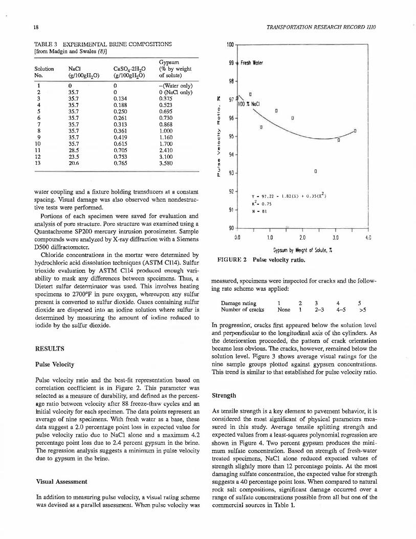
TABLE 3 EXPERIMENTAL BRINE COMPOSITIONS [from Madgin and Swales (8)]
Gypsum Solution NaCl CaS04.2H20 (%by weight No. (g/100gH20) (g/IOOgH20) of solute)
1 0 0 -(Water only) 2 35.7 0 0 (NaCl only) 3 35.7 0.134 0.375 4 35.7 0.188 0.523 5 35.7 0.250 0.695 6 35.7 0.261 0.730 7 35.7 0.313 0.868 8 35.7 0.361 1.000 9 35.7 0.419 1.160
10 35.7 0.615 1.700 11 28.5 0.705 2.410 12 23.5 0.753 3.100 13 20.6 0.765 3.580
water coupling and a fixture holding transducers at a constant spacing. Visual damage was also observed when nondestructive tests were performed.
Portions of each specimen were saved for evaluation and analysis of pore structure. Pore structure was examined using a Quantachrome SP200 mercury intrusion porosimeter. Sample compounds were analyzed by X-ray diffraction with a Siemens DSOO diffractometer.
Chloride concentrations in the mortar were determined by hydrochloric acid dissolution techniques (ASTM C114). Sulfur trioxide evaluation by ASTM Cll4 produced enough variability to mask any differences between specimens. Thus, a Dietert sulfur determinator was used. This involves heating specimens to 2700°F in pure oxygen, whereupon any sulfur present is converted to sulfur dioxide. Gases containing sulfur dioxide are dispersed into an iodine solution where sulfur is determined by measuring the amount of iodine reduced to iodide by the sulfur dioxide.
RESULTS
Pulse Velocity
Pulse velocity ratio and the best-fit representation based on correlation coefficient is in Figure 2. This parameter was selected as a measure of durability, and defined as the percentage ratio between velocity after 88 freeze-thaw cycles and an mitial velocity for each specimen. The data points represent an average of nine specimens. With fresh water as a base, these data suggest a 2.0 percentage point loss in expected value for pulse velocity ratio due to NaCl alone and a maximum 4.2 percentage point loss due to 2.4 percent gypsum in the brine. The regression analysis suggests a minimum in pulse velocity due to gypsum in the brine.
Visual Assessment
In addition to measuring pulse velocity, a visual rating scheme was devised as a parallel assessment. When pulse velocity was
TRANSPORTATION RESEARCH RECORD lllO
""' IW
99
98
I( 97
0 :;; 0 96 II:
>. ~ 95 u 0 ii > 94 G n J 93 Q.
92
91
Fresh Water
" 0
100 r. NaCl a
0
0
Y • 97.22 - l . 82(X) + U.J5(X2
)
R2•0.75
N c 81
a
90 ~.~----.~~,..-~-;-~~~~~~~~~----1
0.0 1.0 2.0 10 4.0
Gypsum by Weight of Solute, r. FIGURE 2 Pulse velocity ratio.
measured, specimens were inspected for cracks and the following rate scheme was applied:
Damage rating Number of cracks
2 None 1
3 2-3
4 4-5
5 >5
Jn progression, cracks first appeared below the solution level and perpendicular to the longitudinal axis of the cylinders. As the deterioration proceeded, the pattern of crack orientation became less obvious. The cracks, however, remained below the solution level. Figure 3 shows average visual ratings for the nine sample groups plotted against gypsum concentrations. This trend is similar to that established for pulse velocity ratio.
Strength
As tensile strength is a key element to pavement behavior, it is considered the most significant of physical parameters measured in this study. Average tensile splitting strength and expected values from a least-squares polynomial regression are shown in Figure 4. Two percent gypsum produces the minimum sulfate concentration. Based on strength of fresh-water treated specimens, NaCl alone reduced expected values of strength slightly more than 12 percentage points. At the most damaging sulfate concentration, the expected value for strength suggests a 40 percentage point loss. When compared to natural rock salt compositions, significant damage occurred over a range of sulfate concentrations possible from all but one of the commercial sources in Table 1.

Pitt el al.
1.0 Fresh Water
100 X NaCl 1.5
2.0
QI 2.5 0
[
;; a D II'. a • 3.0 QI D a E
a
D a 3.5
··4.0
0
4.5 a
-5.0 ---,--l-"Tl--,--,-"T,--..---1---.1--..---1--t
0.0 1.0 2.0 3.0
Gypsum by Weight of Solute, %
FIGURE 3 Visual damage rating.
4.0
Although the statistical regression results in Figure 4 suggest the existence of a relation between strength after freezing and thawing and sulfate concentration in a brine; validity or lack of validity of experimental results can be assessed through analysis of variance and significance tests. Average values for strength as a percentage of fresh water treatment strength and their standard deviations for data in Figure 4 are presented in Table 4. A significance test can be formulated with the null hypothesis being: calcium sulfate in a NaCl brine does not
19
reduce strength. The alternate hypothesis may be stated as: calcium sulfate in the brine reduces strength. This formulation places the burden of proof on the proposed phenomena.
Test statistics computed from experimental data and Student's I-distribution parameters and their appropriate confidence level are also shown in Table 4. A test statistic larger than the I-distribution parameter means that at a particular level of confidence there is evidence that the null hypothesis, or the presumption that calcium sulfate does not reduce strength, is untrue. Additionally, the alternate hypothesis may be accepted. In Table 4 it can be seen that in all but one case the null hypothesis is rejected at a 99 percent or higher confidence level. The one deviation suggests a 97.5 percent confidence level. Thus, sulfates in this experimental environment produce significant reductions in strength.
Pore Structure
For better understanding of mechanisms associated with sulfates in deicing brines, samples from beneath the solution level of specimens subjected to freeze-thaw were evaluated using mercury intrusion to pressures up to 60,000 psi, thus filling pores to 18 angstroms. Shown in Figure 5 is the cumulative volume of mercury intruded as pore volume plotted against pore radius for fresh water, NaCl, and three gypsum percentages. A significant difference in intruded volume occurs between fresh water and brine-treated specimens. More _pores are present in the fresh water mortar. A less dramatic but noticeable difference is also evident between two treatment pairs: (NaCl and 0.73 percent gypsum) and (1.7 and 2.4 percent gypsum). This pore-filling pattern correlates to strength. Sodium chloride and a 0.73 percent gypsum produced an intermediate strength reduction when compared to that for higher sulfate concentrations.
In Figure 5, it is observed that most differences in pore structure occurred in the 100 to 500 angstrom range. By one classification (9) these are small- to medium-sized capillary pores and are known to influence mechanisms for frost action.
TABLE 4 ANALYSIS OF TENSILE STRENGTH DATA
S1rength
Standard Number of Confidence Gypsum Mean Deviation Observations Testa Level (%) CY) (s) (N) Statistic t-parameter (%)
0.0 87.9 16.7 27 0.375 72.7 16.7 27 3.34 2.40 99.0 0.523 67.8 14.4 9 3.22 2.44 99.0 0.695 73.8 20.2 9 2.08 2.44 97.5 0.730 67.9 16.3 18 3.99 2.42 99.0 0.868 65.1 15.5 9 3.61 2.44 99.0 1.000 61.2 12.2 9 5.56 2.44 99.0 1.200 58.2 24.9 18 3.80 2.42 99.0 1.700 66.3 21.6 18 2.98 2.42 99.0 2.400 58.9 13.6 18 4.83 2.42 99.0 3.ioo 60.9 16.5 18 4.22 2.42 99.0 3.600 73.2 14.2 18 2.42 2.42 99.0
aFrom methods outlined in reference 14. bGypsum in saturated. NaCl brine.

20
.r. .. II' c • I. .. Ill I. • .. 0 3 .r. I I L II. .. 0
~
.r. .. II' c I I. .. Ill
90
80
70
60
50
40
Fresh Water
0.0
100 1. NaCl
0 0
'>D 0
0
a a
i Y • 81 . bO - 22 . 64(X) + 5.52(X )
R2'• 0.86
N • 198
1.0 2.0 J.O
Gypsum by Weight of Solute, 1.
FIGURE 4 Tensile strength.
Sample Composition
0
4.0
X-ray diffraction charts for samples from specimens subjected to freezing and thawing in water, in NaCl brine, and in NaCl with 2.4 percent gypsum are presented in Figures 6 through 8. These results are similar and are as anticipated for a mortar
0.1
0 .09
o.oe
,..., 0.07 Ill ....
" ~ 0 .06 E :3 0 ....
0.05 > 0
" u .:!: u g ..... 0.0-4 3
...... u
E ~ 0.03 :3
u
0.02
0.01
TRANSPORTATION RESEARCH RECORD 1110
hydrate in that the specimens are highly a..-norphous but do exhibit peaks for crystalline compounds: calcium hydroxide, quartz, ettringite, and calcium carbonate. The latter compound is attributed to atmospheric carbonation. Differences attributed to the treatments can be seen in intensity of ettringite peaks and the occurrence of a new compound identified as Friedel 's salt, a tricalcium aluminate hydrate involving chlorides (12). Friedel's salt was identified from diffraction peaks at 7.87, 4.70 and 3.81 angstroms. Diffraction peaks at 9.73, 5.61, and 3.88 angstroms identified ettringite .
The following table summarizes diffraction data in relative compound qtJ.antities estimated from peak intensities .
Trealmenl
Water NaCl NaCl+Gypsum
Maximum lnlensity Counls for 100 Percenl Peak
Ettringite
216 260 304
Friedel's Salt
Not present 479 496
These data suggest that ettringite formation is enhanced by NaCl alone and, as might be expected, further enhanced by gypsum. Friedel's salt, not present from fresh water treatment, is promoted by NaCl and further enhanced by gypswn (13). Compounds formed as a result of NaCl and gypsum are thought to be responsible for void filling measured by mercury porosimetry.
Chemical Composition
Averages for chloride and sulfur trioxide measurements and regression results for mortar specimens subjected to different brine treatments are shown in Figure 9. As expected, brine treatments caused a substantial increase in chloride concentra-
533 356 267 213 107 71 53 42 36 31 27 24 21
Pore Radius (onCiJs.)
19 18
FIGURES -Mercury intrusion poroslmetry.

0 -*
E
8
Ettringite - E Calcium Hydroxide - CH Calcium Carbonate - CC Silicia - S
E
~9?~.-o-o~~~-4~.o-o~~~-e~.-o-o~~~-8~. o-o~~~-1....-.0-o~~~-1~.-o-0~~~1~4-.o-0~~~~1 .oo
2044.138 22.07t 14.718 11.042 8.838 7.389 8.321 5.535 S~ TWO - THETA d SPACING LI~~~~~~~~~~~~~~~~~~~~~~~~~~~~ ....... ~~~~~~~~~ -
CH
1 .00 4.924
s
~ .00 2 .00 4.438 4.037 TWO - THETA
FIGURE 6 Diffraction, fresh water sample.
0
~
0 ~ Ill ......
0 -* 0 0
~9?.oo 4.00 B.00 8 . 00 Z 044.138 22.071 14.718 11. 042 =>o TWO - THETA 0. u:il -
CH
0 0 in ......
s
0 ~ 01 .00 1 .00 ~0 . 00 2 .00
5.535 4.924 4.438 4.037 TWO - THETA
FIGURE 7 Diffraction, saturated NaCl brine.
E
s
24.00 2 .00 3.705 3.424
2 .00 3.184
d SPACING
Ettringite - E
F Friedel's Salt - F Calcium Hydroxide - CH Calcium Carbonate - CC Silicia - S
10.00 1 .00 14 .00 8.838 7.389 8.321
d SPACING
s cc
CH
24.00 2 .00 2 .00 3.705 3.424 3.184
d SPACING
cc
E
.
30.00 2.978
1 .00 15.535
30.00 2.978
22
2.0
1.9
1.8
1.7 1.6
L 1.5 D
t'. 1.4 0 ~ 1.3 .. 0 1.2 .. .[ 1.1 DI .. 1.0 ~ 0.9 )\ JI 0.8 .. 0.7 c • 0.6 0 L • 0.5 IL
0.4
0.3 0.2 0.1
0.0
0 ...... *
0
0 0
IC! .....
0 0
F
TRANSPORTATION RESEARCH RECORD 1110
Ettringite - E Friedel' s Salt - F Calcium Hydroxide - CH Calcium Carbonate - CC S1lic1a - S
E
~~~.-o-o~~~-4~.-oo~~~~s~.o-0~~~~0~.o-0~~~~1~.-o-o~~~-1~.-o-o~~~,14-.-00~~~--116.00
:Z:0
44.138 22.071 14.718 11.042 8.838 7.389 8.321 5.535 5~ TWO - THETA d SPACING uo IC!~~~~~~~~-..-~~~~---~~-.-~~~~~~~~~~-..-~~~~~~~-..-...---. ....
0 0
IC! .....
CH
1 .00 4.924
s E
20.00 22.00 4.436 4.037 TWO - THETA
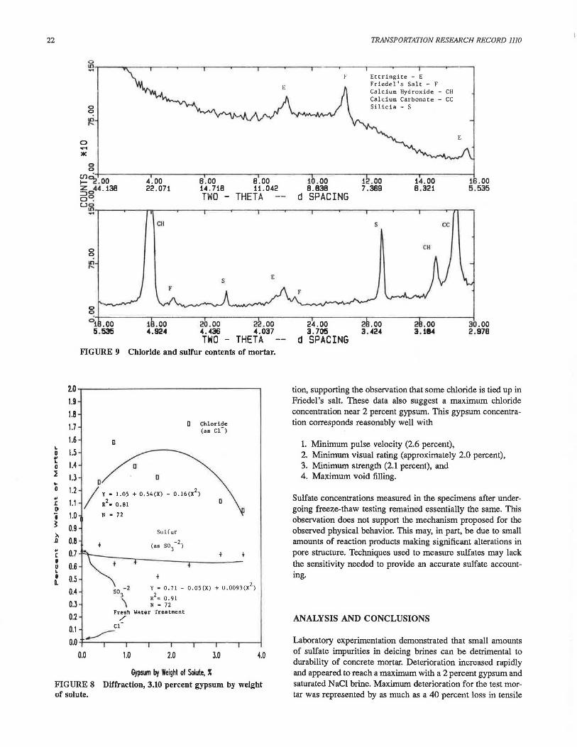
FIGURE 9 Chloride and sulfur contents of mortar.
D Chloride (as Cl-)
D
a a I\• 1.05 + 0.54(X) - 0.16(X2
) R • 0.81
N • 72
Sul( ur
+ -2 (as so
3 )
f
f
Y • 0.71 - O.OS(X) + 0.0093(X2) so - 2 3 R2 ~ 0.91 \ N • 72
Fresh Water Treatment / -Cl __.,,-
0.0 1.0 2.0 3.0 4.0
lljpsum boj Weight of Solute, X
24.00 3.705
d SPACING
s
CH
.00 3.114
cc
30.00 2.978
tion, supporting the observation that some chloride is tied up in Friedel's salt. These data also suggest a maximum chloride concentration near 2 percent gypsum. This gypsum concentration corresponds reasonably well with
1. Minimum pulse velocity (2.6 percent), 2. Minimum visual rating (approximately 2.0 percent), 3. Minimum strength (2.1 percent), and 4. Maximum void filling.
Sulfate concentrations measured in the specimens after undergoing freeze-thaw testing remained essentially the same. This observation does not support the mechanism proposed for the observed physical behavior. This may, in part, be due to small amounts of reaction products making significant alterations in pore structure. Techniques used to measure sulfates may lack the sensitivity needed to provide an accurate sulfate accounting .
ANALYSIS AND CONCLUSIONS
FIGURE 8 Diffraction, 3.10 percent gypsum by weight of solute.
Laboratory experimentation demonstrated that small amounts of sulfate impurities in deicing brines can be detrimental to durability of concrete mortar. Deterioration increased rapidly and appeared to reach a maximum with a 2 percent gypsum and saturated NaCl brine. Maximum deterioration for the test mortar was represented by as much as a 40 percent loss in tensile

Pitt et al.
strength. Similar patterns were observed with pulse velocity measurements and visual damage assessments.
Mechanisms for sulfate-enhanced chloride deterioration are thought to be void filling from formation of Friedel 's salt and additional ettringite. Freidel 's salt formation also appears to be enhanced by the presence of gypsum. This void filling makes mortar more vulnerable to mechanical frost action and premature deterioration.
ACKNOWLEDGMENTS
This research was conducted through the Engineering Research Institute of Iowa State University and sponsored by the Iowa Highway Research Board of the Iowa Department of Transportation and by the Iowa State Mining and Mineral Resources Research Institute under a U.S. Bureau of Mines allotment grant. The opinions, findings, and conclusions of this report are those of the authors and not necessarily those of the Highway Division of the Iowa State Department of Transportation.
REFERENCES
1. S. J. Lefond and C. H. Jacoby. Salt. Industrial Minerals and Rocks. Vol II, 5th ed., American Institute of Mining, Metallurgical, and Petroleum Engineers, Inc., Port City Press, Baltimore, Md., 1983, pp. 1119-1149.
23
2. F. M. Lea. The Chemistry of Cement and Concrete. 3rd ed., Chemical Publishing Co., New York, 1971.
3. Symposium on Sulfate Resistance of Cement. (P. Klieger, ed.). SP-77, American Concrete Institute, De1roit, Mich., 1982.
4. I. Biczok. Concrete Co"osion and Concrete Protection. 8th ed., Chemical Publishing Co., New York, 1972.
5. A. M. Neville. Properties of Concrete. 3rd ed., Pitman Publishing Inc., Marshfield, Mass., 1981.
6. D. W. Kaufmann. Sodium Chloride. Reinhold Publishing Corp., New York, 1960. pp. 365-371.
7. S. Lefond. Handbook of World Salt Resources. Monographs in Geosoience. Plenum Press, New York, 1969, pp. 25-31.
8. W. M. Madgin and D. A. Swales. Solubilities in the System CaSO -NaCl-H 0 at 25 and 35 Degrees. Journal of Applied Chemistry, No. 6, Nov. 1956, pp. 482-487.
9. S. Mindness and J. F. Young. Concrete. Prentice-Hall, Inc., Englewood Cliffs, N.J., 1981.
10. R. E. Oberbolster, J. H. Van Aardt, and M. P. Brandt. Durability of Cementitious Systems. Structure and Performance of Cements. Applied Science Publishers, New York, 1983, pp. 397-410.
11. Standard Specifications for Highway and Bridge Construction, Series of 1977. Issued by State Tran.sportation Commission of Iowa, Ames.
12. Special Report 127: Guide to Compounds of Interest in Cement and Concrete Research. HRB, National Research Council, Washington, D.C., 1972.
13. D. W. Hoffman. Changes in Stru.cture and Chemistry of Cement Mortars Stressed by a Sodium Chloride Solution. Cement and Concrete Research, Vol. 14, 1984, pp. 49-56.
14. C. Chatfield. Statistics for Technology. Halsted Press, John Wiley & Sons, New York, 1978.
Publication of this paper sponsored by Commillee on Performance of Concrete.