summary of international high heat flux component workshop...
TRANSCRIPT

March 16, 2009/ARR 1
Summary of International High Heat FluxComponent Workshop, San Diego, December
2008
A. René RaffrayUniversity of California, San Diego
Co-Organizers: Richard Nygren (SNL) and Dennis Whyte (MIT)
Japan/US Workshop on Power Plant Studies and AdvancedTechnologies with Participation of ChinaUniversity of Tokyo in Kashiwa, Japan
March 16-18, 2009

March 16, 2009/ARR 2
ARIES Town Meetings and Workshops
• The ARIES program organizes town meetings/workshops to provide a forum for discussions between scientists from R&D programs and power plant studies:- To help guide experimental programs towards solutions that lead to an
attractive fusion power plant- To help design studies develop concepts that are consistent with the
understanding of scientists developing those technologies.
• Consistent with ARIES mission statement:- Perform advanced integrated design studies of the long-term fusion
energy embodiments to identify key R&D directions and provide visions for the program.

March 16, 2009/ARR 3
Past ARIES Town Meetings Have Proven Very ValuableMar. 2-3, 1995 ANL Workshop on Liquid Target Divertors
May 10, 1995 ANL Starlite Town Meeting on Structural Materials
Jan. 31, 1996 UCSD Starlite Town Meeting on Low Aspect RatioSpherical Tokamaks
June 19, 1997 UW ARIES Town Meeting on Designing with Brittle Materials
May 6-7, 1998 UCSD ARIES Town Meeting on ST Physics
Jan. 18-19, 2000 ORNL International Town Meeting on SiC/SiCDesign & Material Issues for Fusion Systems
Mar. 6-7, 2001 Livermore ARIES Tritium Town Meeting
May 5-6, 2003 Livermore ARIES Town Meeting on Liquid Wall ChamberDynamics
Sept. 15-16, 2005 PPPL ARIES Compact Stellarator Physics Town Meeting
Starlite
ARIES-RS
ARIES-ST
ARIES-AT
ARIES-IFE
ARIES-CS

March 16, 2009/ARR 4
Background and Goals of Workshop• A topic of high current interest is the apparent disconnect or gap between near term
and long term concepts for high heat flux components (HHFC, and in particulardivertors).
• This is the focus of this workshop aimed at:- better characterizing the international status of current HHFC design concepts for power
plants
- comparing it to the present stage of development and experimental information for near term concepts (ITER-like);
- better understanding how to evaluate where we are with respect to the end goal (power plant HHFC concepts) and what needs to be done to get there.
• The question carries also of course an important physics aspect in realisticallydetermining the expected physics regime of operation in a power plant and thecorresponding heat and particle fluxes on the divertor, and an important materialaspect in designing the HHFC's for accommodation of the threats from the fusionenvironment.
• This topic is also now of particular interest in the USA as it relates to the work beingdone as part of the ReNeW effort.- The objective of the ReNeW project is to help OFES develop a plan for US fusion research
during the ITER era, roughly the next two decades.- It is hoped that the outcome of the workshop will provide some useful information

March 16, 2009/ARR 5
33 Registered Participants(including 8 from EU and 1 from Japan)
1 Abdel-Khalik, Said Georgia Tech. [email protected]
2 Doerner, Russ UCSD [email protected]
3 Escourbiac, Frédéric CEA [email protected]
4 Evans, Todd GA [email protected]
5 Goldston, Rob PPPL [email protected]
6 Harris, Jeff (remotely) PPPL [email protected]
7 Hoelzer, David ORNL [email protected]
8 Konishi, Satoshi Kyoto University [email protected]
9 Lasnier, Charles LLNL [email protected]
10 Leonard, Anthony GA [email protected]
11 Lorenzetto, Patrick F4E [email protected]
12 Malang, Siegfried UCSD Consultant [email protected]
13 Meier, Wayne LLNL [email protected]
14 Merola, Mario ITER IO [email protected]
15 Morley, Neil UCLA [email protected]
16 Neu, Rudolf IPP Garching [email protected]
17 Norajitra, Prachai FZ Karlsruhe [email protected]
18 Nygren, Richard SNL [email protected]
19 Pitts, Richard (remotely) ITER IO [email protected]
20 Raffray, René UCSD [email protected]
21 Rieth, Michael FZ Karlsruhe [email protected]
22 Roedig, Manfred FZ Juelich [email protected]
23 Rognlien, Tom LLNL [email protected]
24 Snead, Lance ORNL [email protected]
25 Stangeby Peter GA [email protected]
26 Tillack, Mark UCSD [email protected]
27 Turnbull, Alan GA [email protected]
28 Tynan, George UCSD [email protected]
29 Uckan, Nermin ORNL [email protected]
30 Wang, Xueren UCSD [email protected]
31 West, Phil GA [email protected]
32 Whyte, Dennis MIT [email protected]
33 Wong, Clement GA [email protected]

March 16, 2009/ARR 6
Agenda

March 16, 2009/ARR 7
• Time does not allow a detailed summary of each presentation
• Example results from different presentations shown to illustrate some of the key observations
• More details will be provided in workshop report/publication
Observations from the Workshop

March 16, 2009/ARR 8
PFC GAP BETWEEN ITER AND POWER PLANT:
1. Divertor materials and conditions
2. Level of R&D effort to-date
3. Steady state and transient loads
4. Plasma/Material Interaction conditions
5. Technology Readiness Level
Major Observations from IHHFC Workshop Include:
March 16, 2009/ARR 9
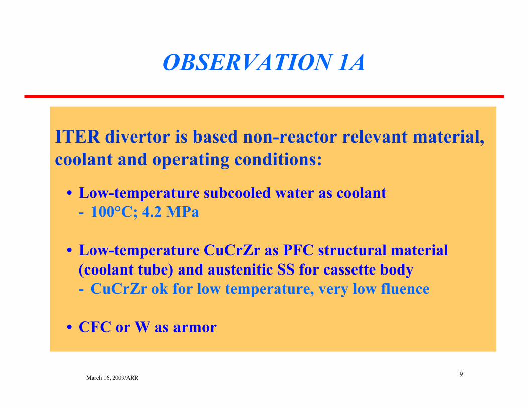
ITER divertor is based non-reactor relevant material,coolant and operating conditions:
• Low-temperature subcooled water as coolant- 100°C; 4.2 MPa
• Low-temperature CuCrZr as PFC structural material (coolant tube) and austenitic SS for cassette body- CuCrZr ok for low temperature, very low fluence
• CFC or W as armor
OBSERVATION 1A

March 16, 2009/ARR 10
ITER Plasma Facing Components (from S. Konishi/S. Suzuki’s presentation)
• 54 Cassettes• Procurement shared among EU, Japan
and RF
Plasma
Troi
dal c
oil
Divertor
First wall/Blanket
6.2m
Test Blanket Module(TBM)
Cross sectional view of Cross sectional view of ITERITER
Outer vertical target (JA)Outer vertical target (JA)
Inner vertical target (EU)Inner vertical target (EU)
Dome(RF)Dome(RF)
CassetteCassettebody (EU)body (EU)
ITER divertor cassette

March 16, 2009/ARR 11
ITER Divertor Tube Configuration (from M. Merola’s presentation)
W monoblock
5 MW/m2
10 MW/m2
W monoblock
Copper Interlayer
CuCrZr Heat SinkSmooth Tube
Plasma-Facing Components
316L(N)-IG CFC monoblock
20 MW/m2 over 10 secCFC monoblockFor first divertor set
Copper Interlayer
CuCrZr Heat SinkSubcooled water flowthrough twisted tape: Toincrease the marginsagainst the Critical HeatFlux
Vertical Targets
XM-19
XM-19

March 16, 2009/ARR 12
Typical tokamak power-plant (DEMO) divertor (atleast in EU and US) based on operating conditions andmaterials very different from ITER:
• He-cooled, W-alloy concepts to accommodate ~10 MW/m2
- He coolant: ~10MPa; ~600-700°C- W-alloy ~700-1300°C- W armor ~1500-1800°C- W-alloy joined to ODS FS
• Also advanced design with Pb-17Li + SiCf/SiC but limited capability to accommodate high heat flux
OBSERVATION 1B

March 16, 2009/ARR 13
He-cooled modular divertor with jet cooling (HEMJ)(from P. Norajitra’s presentation)

March 16, 2009/ARR 14
ARIES T-Tube Divertor Design(from A. R. Raffray’s presentation)
• Design for a max. q’’ of at least 10 MW/m2
• Mid-size configuration with credible manufacturing and assembly procedures (for CS or Tokamak application).
• Cooling with discrete or continuous jets through thin slots (~0.4 mm)
• 10 MPa, ~600-700°C He coolant
• ~600/700°C to1300°C W-alloy
• A number of such T-tubes can beconnected to a common manifold to form desired divertor target plate area.
• He-cooled W-alloy T-tube

March 16, 2009/ARR 15
ITER divertor just went though its final design reviewto evaluate readiness for procurement:
• Mature and optimized component design and technology
• Extensive R&D and testing over last 15 years +
OBSERVATION 2A

March 16, 2009/ARR 16
• The material choice for ITER was performed based on industrially available materials while taking into account their physical and mechanical properties, maintainability, reliability, corrosion performance and safety requirements at the ITER operational conditions.
• Experience from current tokamaks has been taken into account,(plasma facing, diagnostics materials, etc.).
• Knowledge from fission neutron irradiation programs was used.
Strategy for Material Selection(from P. Lorenzetto’s presentation)

March 16, 2009/ARR 17
• Extensive R&D (small to large scale): manufacturing, testing and qualificationeffort (15+ years).
Example of Extensive R&D Program for ITER Divertor(performed in the EU) (from P. Lorenzetto’s presentation)

March 16, 2009/ARR 18
He-cooled W-alloy power plant divertor at theconceptual design stage
• Promising designs, but not optimized, not mature
• Relatively little R&D so far
• Extensive material development, R&D and testing needed
OBSERVATION 2B
March 16, 2009/ARR 1919 | M. Rieth, A. Hoffmann | HHFC, San Diego | December 10, 2008
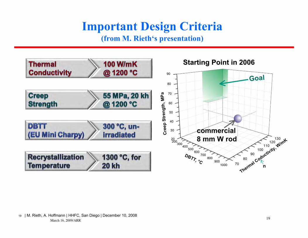
Important Design Criteria(from M. Rieth‘s presentation)
Starting Point in 2006Starting Point in 2006
Goal
commercial8 mm W rod
n

March 16, 2009/ARR 20
Conclusions on W(from M. Rieth‘s presentation)
Microstructure Microstructure significantly defines transition temperatures significantly defines transition temperatures (rod (rod texturetexturemore favorable than that more favorable than that of of platesplates))
Oxide particles (and also potassium doping) promote delamination (but Oxide particles (and also potassium doping) promote delamination (but they are necessary for stabilizing GB they are necessary for stabilizing GB suppr. re-crystallization) suppr. re-crystallization)
Tungsten materials have a DBTT limit of Tungsten materials have a DBTT limit of ≥≥400°C (when produced by400°C (when produced bysintering & deformation, tested according to DIN EN ISO 148-1, sintering & deformation, tested according to DIN EN ISO 148-1, ……))
Notches/edges have Notches/edges have to to be avoided be avoided in in structural partsstructural parts
Optimum Optimum fabrication probably only by aligning grains along the contour fabrication probably only by aligning grains along the contour of of the according part the according part deep drawingdeep drawing, , twistingtwisting, , pressingpressing, , ……
20 | M. Rieth, A. Hoffmann | HHFC, San Diego | December 10, 2008
Long-term creep strength Long-term creep strength and and recrystallization behaviorrecrystallization behaviorhave have still to still to be examinedbe examined
• Also effect of irradiation on embrittlement• Still a lot to do to develop W-alloy material with operating temperature window of ~700/800 to 1300°C and ODS-FS at 700/800°C for joining

March 16, 2009/ARR 21
Example of initial small-scale HHF tests for He-Cooled Wfinger unit
(from P. Norajitra‘s presentation)

March 16, 2009/ARR 22
Initial Work on Validating CFD Code for Divertor Analysis byComparison to Scaled Experimental Results Successful
(from S. Abdel-Khalik‘s presentation)
•• Mock-up to simulate flow geometry of different Mock-up to simulate flow geometry of different divertor divertor conceptsconcepts
•• Good agreement between experimental and numerical resultsGood agreement between experimental and numerical results
•• Validated CFD Codes can be used with confidence to predict performance ofValidated CFD Codes can be used with confidence to predict performance of gas-cooledgas-cooled components with complex geometriescomponents with complex geometries
0.0
50.0
100.0
150.0
200.0
250.0
-10 -5 0 5 10
x (mm)
Te
mp
era
ture
(C
)
Experimental Holes-2
Std. k-eps./ Std. WF
Std. k-eps./ Non-Equil.
WF
RNG k-eps./Non-Equil.
WF
Spalart-Allmaras 0.0
50.0
100.0
150.0
200.0
250.0
-10 -5 0 5 10
x (mm)
Te
mp
era
ture
(C
)
Experimental Holes-5
Std. k-eps./ Std. WF
Std. k-eps./ Non-Equil.
WF
Spalart-Allmaras
FLUENT vs. ExperimentalLow Flow/ Low Power Medium Flow/ Medium Power

March 16, 2009/ARR 23
ITER divertor and PFC’s designed for demandingquasi steady-state and off-normal events
• Low-temperature provides better accommodation margin
• Divertor design load- Steady state: 10 MW/m2
- Slow transient: 20 MW/m2 for <10s
• Off-normal or transient events include:- Disruptions- VDE’s- ELM’s
OBSERVATION 3A

March 16, 2009/ARR 24
• Disruptions- Parallel energy density for thermal quench = 28-45 MJ/m2 near X-point- Deposition time ~ 1-3 ms- Perpendicular energy deposition will be lower, depending on incidence angle - Parallel energy deposition for current quench = 2.5 MJ/m2
- No. of Type I/Type II disruptions = 1000/100
• VDE’s (Type I/Type II):- Energy deposition = 30/60 MJ/m2
- Deposition time ~ 0.05-0.1/0.1-0.2 s- Number of VDE’s = 50/NA
• ELMS:- Parallel energy density for thermal quench (controlled/uncontrolled) ~ 0.77/3.8 MJ/m2
- Deposition time ~ 0.4 ms- Frequency (controlled/uncontrolled) = 4/1 Hz
Transient Loads from ITER Project Integration and LoadSpecification Documents and presentations at 2007 ITER
WG8 Design Review Meeting

March 16, 2009/ARR 25
Wall Loads on PFC’s in ITER(from M. Roedig’s presentation)
• Large initial armor thickness to help accommodate phase change erosion

March 16, 2009/ARR 26
ELM Induced Erosion of CFC and W(from M. Roedig’s presentation)
• Tungsten and CFC surfaces experience significant melting/erosion and cracking above 0.5 MJ/m2
• ELM mitigation/suppression required (RMP ELM Suppression from DIII-D results)

March 16, 2009/ARR 27
Power plant divertor design load much more limited:
• Higher operating temperature, higher fluence reduce accommodation margin
• Steady state divertor design load ~ 10 MW/m2
(very little margin on this design load)
• Very few off-normal events allowed
OBSERVATION 3B

March 16, 2009/ARR 28
Parametric Study of Maximum Phase Change Thickness of a W FWTemperature for Different Disruption Scenarios
(from A. R. Raffray’s presentation)
• 1 mm armor (W) on 4-mm FS FW cooled by He at 483°C with h=5.2 kW/m2-K• Up to ~0.1 mm melt layer and ~0.01 mm evaporation loss per event• Only a few events allowable based on erosion lifetime depending on energy density
4-mm FS1-mm W
Heh = 5 kW/m2-KT = 480°C
EnergyDeposition

March 16, 2009/ARR 29
Summary of Assessment of Off-Normal Energy Depositionon FW
(from A. R. Raffray’s presentation)
• Focus on thermal effects
• EM effects will also be important for FS FW
• Only a few disruptions can be accommodated (depending on the energydensity)
• VDEs cannot be accommodated
• Only limited number of uncontrolled ELM cases can be accommodated
• Controlled ELMs would drastically limit the lifetime of FS armor (a few days)but might be acceptable for W armor
• Avoidance or mitigations of disruptions (and off-normal events) is a keyrequirement for power plant applications

March 16, 2009/ARR 30
ITER PMI Conditions
• 3 materials: Be, W and C
• Low temperature (~200°C)
OBSERVATION 4A

March 16, 2009/ARR 31
Armour materialsCompromise: Plasma Performance Materials Lifetime T retention
~ 680m2 Be first wall low Z compatibility with wide operating range and
low T retention Large experience from JET operation
~ 50 m2 CFC Divertor Target (before Tritium phase) Good resistance under transients (ELMs and
Disruptions) Low Z compatibility with wide range of plasma
regimes (Te,div ~ 1 – 100 eV) Large T retention (co-deposition)
~ 100m2 Tungsten Baffle/Dome Low Erosion, long Lifetime and low T retention Less experience
ITER PFM’s(from P. Lorenzetto’s presentation)

March 16, 2009/ARR 32
Power Plant (DEMO) Conditions
• W armor (or ideally bare FS wall)
• High temperature (~700°C)
• Need fusion testing under these conditions prior to DEMO
OBSERVATION 4B

March 16, 2009/ARR 33
It is Hard to Overstate the Importance of Ambient Temperature forFuel Control and Tritium Retention
(from D. Whyte’s presentation)
• Every major (and minor) modification to the wall surfaces had profound effects on core performance.- E.g. lithium layers (TFTR, NSTX), He discharge cleaning (TFTR, DIII-D, etc), boronizations (DIII-D, C-Mod,
etc), ad infinitum• Can we be so naïve that ~10 orders of magnitude modifications to boundary condition of wall will
not have profound effects on the core?

March 16, 2009/ARR 34
• Material loss rates impact reactor operation– Impurity content in core– Lifetime of wall– Changing thickness will alter thermal gradients in armor which
will in turn effect tritium inventory in the armor– Material mixing
• Increases in material loss rates will provide morematerial available for co-deposition with fuel
• Very little PMI data at elevated (DEMO relevant) walltemperature is available
PMI at elevated temperature can influencesurface material loss rate(from R. Doerner’s presentation)

March 16, 2009/ARR 35
ITER PFC well ahead on development scale
• TRL 8-9 for specific PFC design
OBSERVATION 5A
March 16, 2009/ARR 36
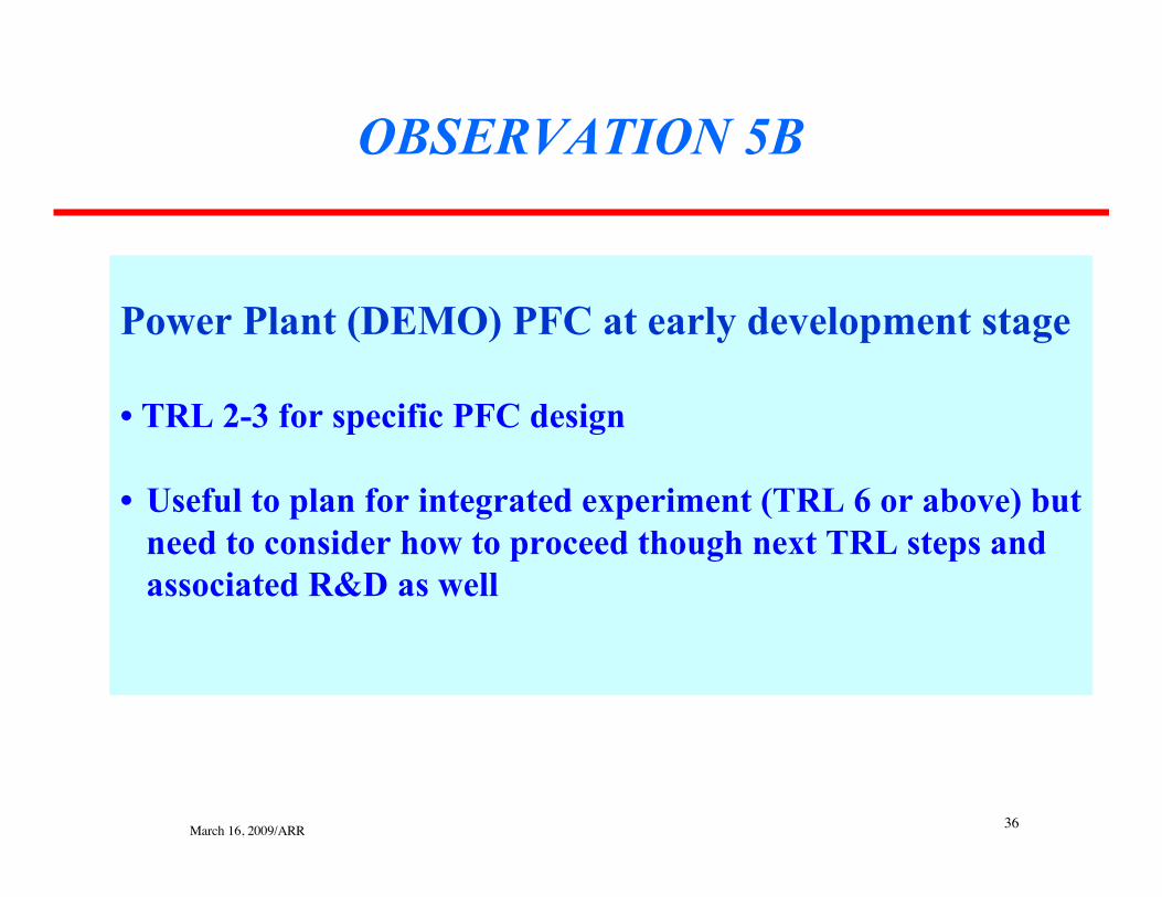
Power Plant (DEMO) PFC at early development stage
• TRL 2-3 for specific PFC design
• Useful to plan for integrated experiment (TRL 6 or above) butneed to consider how to proceed though next TRL steps and associated R&D as well
OBSERVATION 5B

March 16, 2009/ARR 37
TRL’s Applied to PFC’s (from M. Tillack’s presentation)
Issue-Specific Description Program Elements
1 System studies to define parameters, tradeoffs and requirements onheat & particle flux level, effects on PFC’s. Design studies, basic research
2 PFC concepts including armor and cooling configuration explored.Critical parameters characterized. PMI and edge plasma modeling. Code development, applied research
3Data from coupon-scale heat and particle flux experiments; modelingof governing heat and mass transfer processes as demonstration offunction of PFC concept.
Small-scale facilities:e.g., e-beam and plasma simulators
4Bench-scale validation through submodule testing in lab environmentsimulating heat or particle fluxes at prototypical levels over long times,mockups under representative neutron irradiation level/duration.
Larger-scale facilities for submoduletesting, high-temperature + all expected
conditions. Neutron irradiation (fission).
5Integrated module testing of PFC concept in an environmentsimulating the integration of heat, particle, neutron fluxes atprototypical levels over long times. Coupon irradiation testing of PFCarmor and structural material to end-of-life fluence.
Integrated large facility: Prototypicalplasma particle + heat flux (e.g. anupgraded DIII-D/JET?) IFMIF?
6Integrated testing of the PFC concept subsystem in an environmentsimulating the integration of heat & particle fluxes and neutronirradiation at prototypical levels over long times.
Integrated large test facility withprototypical plasma particle & heat flux,
neutron irradiation.
7 Prototypic PFC system demonstration in a fusion machine. Fusion machine, e.g. ITER (w/ prototypicdivertor), CTF
8 Actual PFC system demonstration and qualification in a fusion energydevice over long operating times. CTF
9 Actual PFC system operation to end-of-life in a fusion reactor withprototypical conditions and all interfacing subsystems. DEMO (1st of a kind power plant)
Power plant relevant high-temperature gas-cooled PFC’s
Low-temperature water-cooled PFC’s for ITER

March 16, 2009/ARR 38
1. Divertor materials and conditionsA. ITER: 100°C subcooled water, CuCrZr, W/CFC, austenitic SSB. Power plant (Demo): 600-700°C He, W-alloy, ODS FS
2. Level of R&D effortA. Extensive R&D for ITER divertor (15 years +): at the edge of procurementB. R&D in early stages for power plant divertor material and configuration (must be
realistic about time and effort required)
3. Steady state and transient loadsA. ITER divertor designed for demanding steady-state and off-normal conditionsB. Power plant q’’ on divertor limited to ~10 MW/m2; no VDE’s; very few
disruptions per year.
4. Plasma/Material Interaction ConditionsA. ITER PMI: 3 materials (Be, C, W), low wall temperature (~200°C)B. Power plant PMI: W (bare wall?), high wall temperature (~700°C) (need testing
under these conditions)
5.Technology Readiness LevelA. ITER PFC toward the end of TRL scaleB. Power plant PFC at early TRL’s (providing a guide as to what is needed next)
Major Observations from IHHFC Workshop Include:

March 16, 2009/ARR 39
Please Consult the IHHFC WorkshopWebsite for More Information
http://aries.ucsd.edu/IHHFC/index.html