summary of models of fuse-links for semiconductor …
TRANSCRIPT
Varius
F3
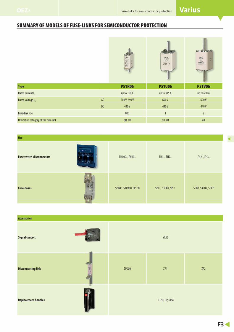
SUMMARY OF MODELS OF FUSE-LINKS FOR SEMICONDUCTOR PROTECTION
Type P51R06 P51U06 P51V06Rated current In up to 160 A up to 315 A up to 630 A
Rated voltage Un AC 500 V, 690 V 690 V 690 V
DC 440 V 440 V 440 V
Fuse-link size 000 1 2
Utilization category of the fuse-link gR, aR gR, aR aR
Use
Fuse switch-disconnectors FH000.., FH00.. FH1.., FH2.. FH2.., FH3..
Fuse-bases SPB00. S3PB00. SPF00 SPB1, S3PB1, SPF1 SPB2, S3PB2, SPF2
Accessories
Signal contact VL50
Disconnecting link ZP000 ZP1 ZP2
Replacement handles D1PH, DP, DPM
Fuse-links for semiconductor protection
Varius
F13
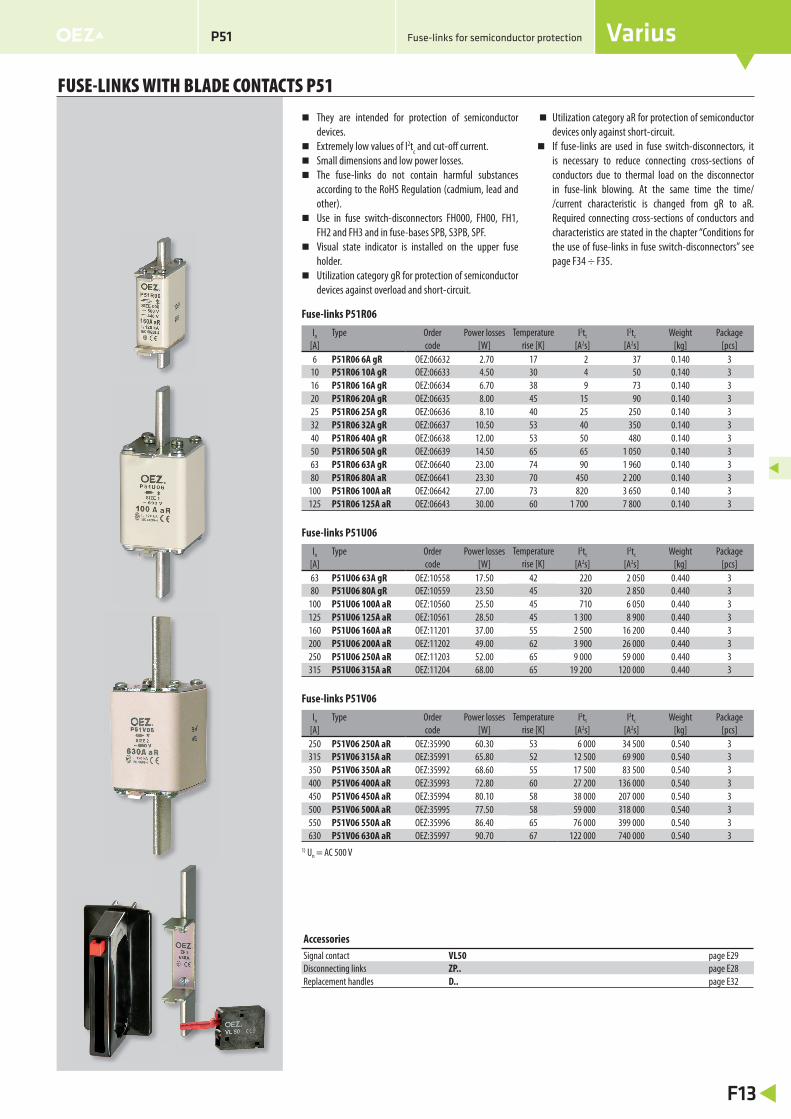
FUSE-LINKS WITH BLADE CONTACTS P51
They are intended for protection of semiconductor
devices.
Extremely low values of I2tc and cut-off current.
Small dimensions and low power losses.
The fuse-links do not contain harmful substances
according to the RoHS Regulation (cadmium, lead and
other).
Use in fuse switch-disconnectors FH000, FH00, FH1,
FH2 and FH3 and in fuse-bases SPB, S3PB, SPF.
Visual state indicator is installed on the upper fuse
holder.
Utilization category gR for protection of semiconductor
devices against overload and short-circuit.
Utilization category aR for protection of semiconductor
devices only against short-circuit.
If fuse-links are used in fuse switch-disconnectors, it
is necessary to reduce connecting cross-sections of
conductors due to thermal load on the disconnector
in fuse-link blowing. At the same time the time/
/current characteristic is changed from gR to aR.
Required connecting cross-sections of conductors and
characteristics are stated in the chapter “Conditions for
the use of fuse-links in fuse switch-disconnectors” see
page F34 ÷ F35.
Fuse-links for semiconductor protectionP51
Accessories
Signal contact VL50 page E29
Disconnecting links ZP.. page E28
Replacement handles D.. page E32
Fuse-links P51R06
In Type Order Power losses Temperature
rise [K]
I2tt I2tc Weight Package
[A] code [W] [A2s] [A2s] [kg] [pcs]
6 P51R06 6A gR OEZ:06632 2.70 17 2 37 0.140 3
10 P51R06 10A gR OEZ:06633 4.50 30 4 50 0.140 3
16 P51R06 16A gR OEZ:06634 6.70 38 9 73 0.140 3
20 P51R06 20A gR OEZ:06635 8.00 45 15 90 0.140 3
25 P51R06 25A gR OEZ:06636 8.10 40 25 250 0.140 3
32 P51R06 32A gR OEZ:06637 10.50 53 40 350 0.140 3
40 P51R06 40A gR OEZ:06638 12.00 53 50 480 0.140 3
50 P51R06 50A gR OEZ:06639 14.50 65 65 1 050 0.140 3
63 P51R06 63A gR OEZ:06640 23.00 74 90 1 960 0.140 3
80 P51R06 80A aR OEZ:06641 23.30 70 450 2 200 0.140 3
100 P51R06 100A aR OEZ:06642 27.00 73 820 3 650 0.140 3
125 P51R06 125A aR OEZ:06643 30.00 60 1 700 7 800 0.140 3
Fuse-links P51U06
In Type Order Power losses Temperature
rise [K]
I2tt I2tc Weight Package
[A] code [W] [A2s] [A2s] [kg] [pcs]
63 P51U06 63A gR OEZ:10558 17.50 42 220 2 050 0.440 3
80 P51U06 80A gR OEZ:10559 23.50 45 320 2 850 0.440 3
100 P51U06 100A aR OEZ:10560 25.50 45 710 6 050 0.440 3
125 P51U06 125A aR OEZ:10561 28.50 45 1 300 8 900 0.440 3
160 P51U06 160A aR OEZ:11201 37.00 55 2 500 16 200 0.440 3
200 P51U06 200A aR OEZ:11202 49.00 62 3 900 26 000 0.440 3
250 P51U06 250A aR OEZ:11203 52.00 65 9 000 59 000 0.440 3
315 P51U06 315A aR OEZ:11204 68.00 65 19 200 120 000 0.440 3
Fuse-links P51V06
In Type Order Power losses Temperature
rise [K]
I2tt I2tc Weight Package
[A] code [W] [A2s] [A2s] [kg] [pcs]
250 P51V06 250A aR OEZ:35990 60.30 53 6 000 34 500 0.540 3
315 P51V06 315A aR OEZ:35991 65.80 52 12 500 69 900 0.540 3
350 P51V06 350A aR OEZ:35992 68.60 55 17 500 83 500 0.540 3
400 P51V06 400A aR OEZ:35993 72.80 60 27 200 136 000 0.540 3
450 P51V06 450A aR OEZ:35994 80.10 58 38 000 207 000 0.540 3
500 P51V06 500A aR OEZ:35995 77.50 58 59 000 318 000 0.540 3
550 P51V06 550A aR OEZ:35996 86.40 65 76 000 399 000 0.540 3
630 P51V06 630A aR OEZ:35997 90.70 67 122 000 740 000 0.540 3
1) Un = AC 500 V

Varius
F14
P51
FUSE-LINKS WITH BLADE CONTACTS P51
Fuse-links for semiconductor protection
Type P51R06 P51U06 P51V06
Standards IEC 60269-1, -2, -4; IEC 60269-1, -2, -4; IEC 60269-1, -2, -4;
EN 60269-1, -4 EN 60269-1, -4 EN 60269-1, -4
EN 60269 EN 60269 EN 60269
Approval marks
Rated operating voltage Un AC 500 V, 690 V 690 V 690 V
DC 440 V 440 V 440 V
Rated operating current In 6 ÷ 160 A 63 ÷ 315 A 250 ÷ 630 A
Rated frequency fn 50 Hz 50 Hz 50 Hz
Rated breaking capacity I1 AC 120 kA 120 kA 120 kA
(RMS) DC 50 kA 50 kA 50 kA
Utilization category gR, aR gR, aR aR
Size 000 1 2
Signalizace VL50 VL50 VL50
Specifi cations
Dimensions
TypeA B D H J K L M
[mm]
P51R06 53.0 21 51.5 15 43 6 78.5 35
P51U06 62.5 44 70.5 20 53 6 135.0 40
P51V06 68±1.3 50±1.3 70.5±2 25 61 6 150±2 48±0.8

Cut-off characteristic
P51U06 gR, aR
I [A]n
2502001601251008063
I [A
]c
1
2
3
4
5
6
10
10
5
5
10
5
10
10
5
5
10
I [A]p
10 5 10 5 10 5 10 1052 3 4 5 6
315
Un = AC 690 V
Cut-off characteristic
P51R06 gR, aR
Prearcing time/current characteristic
P51R06 gR, aR
Varius
F15
FUSE-LINKS WITH BLADE CONTACTS P51
Fuse-links for semiconductor protectionP51
Characteristics
1010 510 5510
5
5
5
5
5
5
5
5
10
10
10
10
10
10
10
10
10
I [A]
vt [
s]
p
1 2 3 4
-4
-3
-2
-1
0
1
2
3
4
80 100 125In [A] 1606 10 16 20 25 32 40 50 63
1 s
1 hr
1 ms
401 min
3020
2
4
20
64
2
10
100
10
10
Un = AC 500/690 V
10
10
10
10
10
10
5
5
5
5
5
10 5 510 10 5 10 5 101 2 3 4 5
0
1
2
3
4
5
nI[A]
6101620253240506380100125160
I [A]p
cI [
A]
Un = AC 500/690 V
Prearcing time/current characteristic
P51U06 gR, aR
315250
1 s
1 hr
1010 510 55I [A]
vt [
s]
1 ms
401 min
30
p
6380
100In [A] 125
10
5
5
5
5
5
5
5
10
10
10
10
10
10
10
10
10
160200
4
3
2
1
0
-1
-2
-3
-4
1 432
20
2
4
20
64
2
10
100
10
10
Un = AC 690 V

t [s
]v
4
-4
-3
-2
-1
0
2
1
3
10
10
5
5
5
10
10
10
5
5
10
5
10
10
5
5
10
250315
350400 500
450 550630nI [A]
I [A]p
2 3 45 105 10 5 10
1 ms
1 s
1 min40
1 hr
30
10
100
2
20
2
20
10
46
10
4
Un = AC 690 V
630
500
400350315250
550
450
nI [A]
I [A
]c
2
3
4
5
6
10
5
10
5
10
10
5
5
10
I [A]p
10 5 10 5 10 5 102 3 4 5
Un = AC 690 V
Prearcing time/current characteristic
P51V06 aR
Cut-off characteristic
P51V06 aR
Varius
F16
P51
FUSE-LINKS WITH BLADE CONTACTS P51
Fuse-links for semiconductor protection
Characteristics
Correction factor „k“ of I2tc dependence on operating voltage U
(I2tc)f(U) = k x I2tc
P51R06
Overvoltage dependence on operating voltage
P51R06
0
0,4
0,6
0,8
1,0
1,2
0 200 400 600 800
0,2
k
U [V]
8006004002000
200
1 200
1 000
800
600
400
0
1 600
1 800
1 400
U [V]
U
[V]
m

Varius
F17
FUSE-LINKS WITH BLADE CONTACTS P51
Fuse-links for semiconductor protectionP51
Characteristics
Overvoltage dependence on operating voltage
P51U06, P51V06
Correction factor „k“ of I2tc dependence on operating voltage U
(I2tc)f(U) = k x I2tc
P51U06, P51V06
0 200 400 600 8000
0,4
0,6
0,8
1,0
1,2
0,2
1,3
k
U [V]
8006004002000
200
1 200
1 000
800
600
400
0
1 600
1 800
1 400
U [V]
U
[V]
m

Type „S“ is mainly used on fuse-links over AC 690 V,
which are not equipped with visual state indicator or
remote signalling
State signalling is ensured by means of signalling device
S41, S42 or S43, which is part of the fuse-links of type
P40U10S, P50U10S, P50V10 or P50V16S.
Type „T“ is mainly used on fuse-links up to AC 690 V,
which are standardly equipped on the upper fuse holder
by a mount for installation of the signal contact VL50.
The signal contact VL50 is ordered separately.
For fuse-links P50O06 and P52U06 it is possible to use
both „T“ signalling and „S“ signalling by means of the
state signalling set S-P50U06.
Possibility of addition of fuse-link state signalling
device on fuse-links of type P40V10, P50U10, P50V10
and P50V16 - signalling device S41, S42, S43 signalling
device holders. Consultation with the manufacturer is
necessary.
Signal contact VL41F must be ordered separately. VL41F
Connection is performed by means of sleeves on fl at
connector wide 2.8 mm.
Remote signalling of fuse state
Varius
F30
ACCESSORIES FOR FUSE-LINKS FOR SEMICONDUCTOR PROTECTION
Fuse-links for semiconductor protection
Signal contact for remote signalling of state of fuse-links for semiconductor protection
Type Order Weight Package
code [kg] [pcs]
VL41F OEZ:18620 0.020 1
VL50 OEZ:06528 0.015 1
For other technical parameters of VL50 see page E29
Signalling sets of P50U06 and P52U06 fuses-links state
Type Order Rated voltage Lenght Weight Package
code Un [AC/V] [mm] [kg] [pcs]
S-P50U06 OEZ:11890 690 61.5 0.002 1
The set contains: signalling device S41 + lower and upper holder
Signalling device of state of fuse-links for semiconductor protection
Type Order Rated voltage Lenght Weight Package
code of fuse-links Un [AC/V] [mm] [kg] [pcs]
S41 OEZ:06522 690 61.5 0.006 1
S42 OEZ:06578 1 000 93.0 0.008 1
S43 OEZ:10450 1 800 150.5 0.011 1
Holders for signalling device S41, S42 a S43
Type Order Description Weight Package
code [kg] [pcs]
586506Z00 OEZ:06527 horní držák k S4. 0.011 1
586523Z00 OEZ:06526 dolní držák k S4. 0.011 1
Type VL41F
Standards IEC 60269-1, -2, -4
EN 60269-1, -4
EN 60269
Approval marks
Rated current In for AC 250 V 5 A
for DC 250 V 0.2 A
Rated insulation voltage Ui 4 KV
Electrical endurance operating cycles 2 000
Specifi cations
Types of state signalling of fuses for semiconductor protection
P50
K06
P50
N06
P50
R06
P51
R06
P50
T06
P50
U06
P52
U06
P51
U06
P51
V06
P40
U10
P50
U10
P50
V10
P50
V16
Signalling type
- - T T T T, S 1) T, S 1) T T S S S S
- - VL50 VL50 VL50 VL50, S41 VL50, S41 VL50 VL50 S42 S42 S42 S431) The set S-P50U06 can be bought as accessories

Varius
F31
ACCESSORIES FOR FUSE-LINKS FOR SEMICONDUCTOR PROTECTION
Fuse-links for semiconductor protection
Fuse for semiconductor protection with signalling of type T
State of contacts with installed signal contact VL41F
on the signalling device:
fuse not blown – contacts P – 2 closed.
Návěstní kontakt VL50
8 3514
C NO NC
C NO NC
State of contacts with installed signal contact VL50 on
the fuse-link:
fuse not blown – contacts C – NC closed.
Fuse for semiconductor protection with signalling of type S
see page D16
Signal contact VL50
Návěstní kontakt VL41F
Návěstní zařízení S4.
VL41F2A
AC 250 V
Signal contact VL41F
Signalling device S4.
Varius
F32
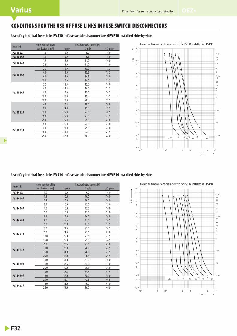
CONDITIONS FOR THE USE OF FUSE-LINKS IN FUSE SWITCH-DISCONNECTORS
Fuse-links for semiconductor protection
Use of cylindrical fuse-links PV510 in fuse switch-disconnectors OPVP10 installed side-by-side
Use of cylindrical fuse-links PV514 in fuse switch-disconnectors OPVP14 installed side-by-side
Fuse-linkCross-section of Cu
conductor [mm2]
Reduced rated current [A]
1-pole 3-pole ≥ 7-pole
PV510 6A 1.0 6.0 6.0 6.0
PV510 10A 1.5 10.0 9.5 9.0
PV510 12A1.5 12.0 11.0 10.0
2.5 12.0 11.0 11.0
PV510 16A
2.5 16.0 13.0 12.5
4.0 16.0 13.5 12.5
6.0 16.0 14.5 14.0
10.0 16.0 16.0 15.5
PV510 20A
2.5 18.5 15.0 14.0
4.0 19.5 16.0 15.5
6.0 20.0 17.0 16.5
10.0 20.0 19.0 17.5
16.0 20.0 20.0 19.5
PV510 25A
4.0 22.5 18.5 18.0
6.0 24.0 19.5 19.5
10.0 25.0 22.5 20.5
16.0 25.0 23.5 22.5
25.0 25.0 25.0 25.0
PV510 32A
6.0 26.0 22.5 22.0
10.0 28.0 25.0 23.0
16.0 31.0 27.0 25.5
25.0 32.0 30.0 28.0
Fuse-linkCross-section of Cu
conductor [mm2]
Reduced rated current [A]
1-pole 3-pole ≥ 7-pole
PV514 6A 1.0 6.0 6.0 6.0
PV514 10A1.5 10.0 10.0 10.0
2.5 10.0 10.0 10.0
PV514 16A
2.5 16.0 13.0 12.0
4.0 16.0 15.0 14.0
6.0 16.0 15.5 15.0
PV514 20A
2.5 17.5 16.5 16.0
4.0 19.5 17.5 16.5
6.0 20.0 17.5 17.5
PV514 25A
4.0 23.5 21.0 20.5
6.0 24.5 21.5 21.0
10.0 25.0 23.5 23.5
16.0 25.0 25.0 24.5
PV514 32A
6.0 26.5 23.5 22.0
10.0 28.0 26.0 24.5
16.0 31.0 28.0 27.5
25.0 32.0 30.5 29.5
PV514 40A
10.0 34.0 31.0 30.0
16.0 37.5 34.0 33.0
25.0 40.0 36.5 36.0
PV514 50A
10.0 38.5 34.5 33.5
16.0 42.0 38.0 36.0
25.0 46.5 42.5 40.5
PV514 63A16.0 51.0 46.0 44.0
25.0 56.0 50.0 49.0
Prearcing time/current characteristic for PV510 installed in OPVP10
1010 510 5510
5
5
5
5
5
5
5
5
10
10
10
10
10
10
10
10
100 1 2 3
-4
-3
-2
-1
0
1
2
3
4
I [A]n 3212 20106 16 25
1 s
1 hr
1 ms
401 min
3020
2
4
20
64
2
10
100
10
10
vt [
s]
I [A]p
nI [A]503220
63402516106
4
3
2
1
0
-1
-2
-3
-4
321010
10
10
10
10
10
10
10
10
5
5
5
5
5
5
5
5
10 5 510 510 10
30
1 min40
1 ms
1 hr
1 s
10
10
100
10
2
46
20
4
2
20
I [A]p
vt [
s]
Prearcing time/current characteristic for PV514 installed in OPVP14

Varius
F33
CONDITIONS FOR THE USE OF FUSE-LINKS IN FUSE SWITCH-DISCONNECTORS
Fuse-links for semiconductor protection
Use of cylindrical fuse-links PV510 in fuse switch-disconnectors OPVP10 installed side-by-side
Prearcing time/current characteristic for PV52 installed in OPVP22Fuse-link
Cross-section of Cu
conductor [mm2]
Reduced rated current [A]
1-pole 3-pole 5-pole 7-pole 10-pole
PV522 25A
4 25.0 23.0 21.5 21.5 21.0
6 25.0 23.0 23.0 23.0 22.5
10 25.0 25.0 24.5 24.5 24.5
PV522 32A
6 30.5 27.0 26.5 26.5 26.0
10 32.0 29.0 28.5 28.0 28.0
16 32.0 31.5 30.5 30.0 30.0
25 32.0 32.0 32.0 32.0 32.0
PV522 40A
10 36.5 32.5 32.0 31.5 31.5
16 39.5 36.0 35.5 34.5 34.5
25 40.0 38.0 36.5 36.5 36.5
PV522 50A
10 41.0 37.5 36.0
16 44.0 39.5 38.5 38.0 38.0
25 48.0 42.5 42.0 41.5 41.5
35 50.0 46.0 46.0 45.0 44.0
PV522 63A
16 51.5 46.0 44.5 44.5 44.0
25 56.0 50.0 49.5 49.0 48.5
35 60.0 54.5 53.5 53.0 52.5
50 63.0 58.5 57.5 56.0 55.0
PV522 80A
25 67.0 59.0 58.5 57.0 57.0
35 69.0 64.0 62.5 62.0 61.0
50 72.0 67.0 65.0 65.0 64.0
PV522 100A35 81.0 75.0 74.0 73.0 71.0
50 85.0 80.0 79.0 79.0 78.0
PV522 125A 50 102.0 95.0 93.0 92.0 91.0
20
2
4
20
64
2
10
100
10
10
1 s
1 hr
1010 3 4510 5510
5
5
5
5
5
5
5
5
10
10
10
10
10
10
10
10
10
1 ms
401 min
30
1 2
-4
-3
-2
-1
0
1
2
3
4
25 40 63 10032 50 80 125I [A]n
vt [
s]
I [A]p

Varius
F34
CONDITIONS FOR THE USE OF FUSE-LINKS IN FUSE SWITCH-DISCONNECTORS
Fuse-links for semiconductor protection
P51R06 P51R06
Use of fuse-links with blade contacts in fuse switch-disconnectors
FH000 FH00Fuse-link Cross-section of Cu
conductor [mm2]Reduced rated current [A] Reduced rated current [A]
P51R06 6A
1 6 6
1.5 6 6
2.5 6 6
4 6 6
P51R06 10A
1 10 10
1.5 10 10
2.5 10 10
4 10 10
6 10 10
P51R06 16A
1.5 16 16
2.5 16 16
4 16 16
6 16 16
10 16 16
P51R06 20A
1.5 20 20
2.5 20 20
4 20 20
6 20 20
10 20 20
P51R06 25A
1.5 25 25
2.5 25 25
4 25 25
6 25 25
10 25 25
16 25 25
P51R06 32A
2.5 28 28
4 28 28
6 30 30
10 30 30
16 32 32
25 32 32
P51R06 40A
2.5 28 28
4 28 28
6 30 30
10 30 30
16 32 32
25 32 32
P51R06 50A
6 40 40
10 40 40
16 42 42
25 47 47
35 50 50
50 50 50
FH000 FH00Fuse-link Cross-section of Cu
conductor [mm2]Reduced rated current [A] Reduced rated current [A]
P51R06 63A
6 45 45
10 45 45
16 47 47
25 50 50
35 50 50
50 53 53
70 60 60
P51R06 80A
6 55 55
10 58 58
16 60 60
25 64 64
35 64 64
50 68 68
70 75 75
95 79 79
P51R06 100A
16 68 68
25 72 72
35 72 72
50 77 77
70 85 85
95 90 90
P51R06 125A
16 80 80
25 85 85
35 87 87
50 90 90
70 100 100
95 105 105
P51R06 160A
16 97 97
25 ÷ 35 100 100
50 110 110
70 120 120
95 125 125
Varius
F35
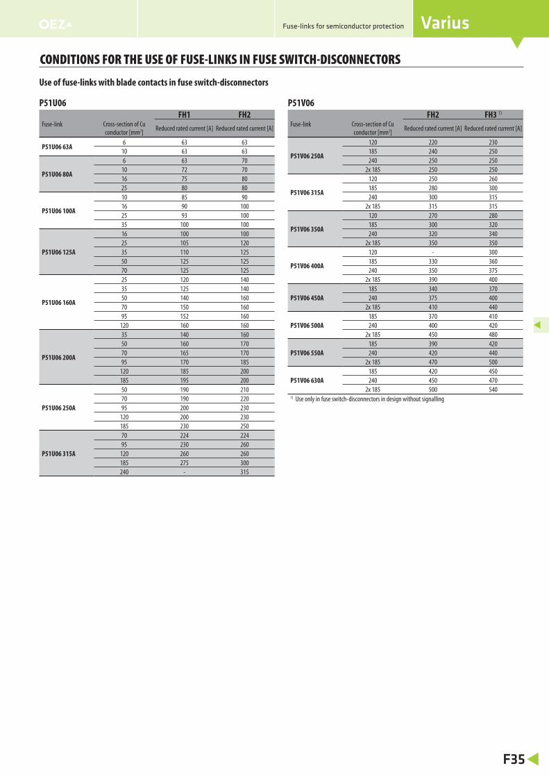
CONDITIONS FOR THE USE OF FUSE-LINKS IN FUSE SWITCH-DISCONNECTORS
Fuse-links for semiconductor protection
P51V06
Use of fuse-links with blade contacts in fuse switch-disconnectors
FH2 FH3 1)
Fuse-link Cross-section of Cu
conductor [mm2]Reduced rated current [A] Reduced rated current [A]
P51V06 250A
120 220 230
185 240 250
240 250 250
2x 185 250 250
P51V06 315A
120 250 260
185 280 300
240 300 315
2x 185 315 315
P51V06 350A
120 270 280
185 300 320
240 320 340
2x 185 350 350
P51V06 400A
120 - 300
185 330 360
240 350 375
2x 185 390 400
P51V06 450A
185 340 370
240 375 400
2x 185 410 440
P51V06 500A
185 370 410
240 400 420
2x 185 450 480
P51V06 550A
185 390 420
240 420 440
2x 185 470 500
P51V06 630A
185 420 450
240 450 470
2x 185 500 5401) Use only in fuse switch-disconnectors in design without signalling
P51U06
FH1 FH2Fuse-link Cross-section of Cu
conductor [mm2]Reduced rated current [A] Reduced rated current [A]
P51U06 63A6 63 63
10 63 63
P51U06 80A
6 63 70
10 72 70
16 75 80
25 80 80
P51U06 100A
10 85 90
16 90 100
25 93 100
35 100 100
P51U06 125A
16 100 100
25 105 120
35 110 125
50 125 125
70 125 125
P51U06 160A
25 120 140
35 125 140
50 140 160
70 150 160
95 152 160
120 160 160
P51U06 200A
35 140 160
50 160 170
70 165 170
95 170 185
120 185 200
185 195 200
P51U06 250A
50 190 210
70 190 220
95 200 230
120 200 230
185 230 250
P51U06 315A
70 224 224
95 230 260
120 260 260
185 275 300
240 - 315