summary of recent inducer testing at msfc and future plans
TRANSCRIPT

Summary of Recent Inducer Testing at MSFC and Future Plans
2003 Thermal and Fluids Analysis WorkshopAugust 18-22
Stephen SkelleyFluid Physics and Dynamics Group
NASA/Marshall Space Flight Center

Agenda
• Water Flow Test History• Water Test Facility• Recent
– Inducer Hydrodynamic Forces– RS-83 Main Lox Inducer Performance
• Current and Future– RS-84 Main Lox Inducer Performance and Blade Loads– Pump Dynamic Transfer Functions: Mass Flow Gain and
Cavitation Compliance• Test Team

Water Flow Test History1987 to 1988: SSME Fuel Pump Inlet Tests, Passive and Active1990: SSME Lox Pump Radial Sideloads1992: Inducer Test Loop (ITL) Operational1992: SSME High-Pressure Lox Inducer Synchronous Vibration1995: Pump Test Equipment (PTE) Operational1995 to 1998: Alternate SSME Fuel Pump Impeller (6 Designs)1995: SSME High-Pressure Lox Inducer Blade Loads1996: SSME High-Pressure Lox Inducer Tip Clearance Effects1997 to 1998: 2nd Source Lox Inducer and Modified Inlet Vane
SSME High-Pressure Fuel Pump Inlet
SSME High-Pressure Lox Inducer
SSME Lox Pump Radial Sideloads
Instrumented SSME High-Pressure Lox Inducer

Water Flow Test History1999: Fastrac/MC-1 Lox Pump 2000: Simplex Lox Pump Inducer2000 to 2001: Baseline Unshrouded Impeller Tip Clearance Effects2001: Advanced Unshrouded Impeller Tip Clearance Effects2001: Cavitation-Induced Hydrodynamic Forces2002: Inducer Test Loop Upgraded2002: RS-83 Main Lox Pump Inducer2003: COBRA Low Pressure Lox Pump2003: RS-84 Main Lox Pump Inducer2004: RS-84 Main Lox Inducer Blade Loads
SSME High-Pressure Lox Inducer
Simplex Inducer
Fastrac/MC-1 Lox Pump

Water Test Facility

Water Test Facility
FLOW
Slave Pump Flow Control Valve
Reservoir
Test Article Inlet
Test Article Exit
Drive Motor Stand
Facility Operating Conditions
Shaft Speed: up to 6000 rpm
Shaft Torque: up to 100 ft-lbf
Flow Rate: up to 2900 gpm
Inlet Pressure: 3 to 50 psia
Discharge Pressure: up to 375 psia
Water Temperature: 60 to 120 deg F

Water Test Facility
FLOW
6-inch Turbine Flow MeterTest Article Discharge
Test Article Inlet
FLOW
50 hp Boost Pump

Water Test Facility

• 6-component force and moment measurement device (“Rotating Balance”) validated in water at engine-equivalent operating conditions with the SSME high-pressure Lox inducer.
Inducer Hydrodynamic Forces

Inducer Hydrodynamic Forces
Inlet guide vane assembly used to simulate volute exit condition (proper radial velocity gradient and incidence) in axial configuration.
Inducer Diameter = 5.160 inch (Full Scale)

• Sensitivity confirmed by directly measuring imbalance in air and buoyancy in water.
Inducer Hydrodynamic Forces
Clean Assembly
With Added Mass
Wet
Dry
Difference = Buoyancy
NF
SF
YM
PM
Computed Maximum Imbalance*
Measured Imbalance
Measured Imbalance = 0.058 ± 0.015 oz-inDifference (Added Mass - Clean) = 0.596 ± 0.023 oz-inExpected Difference = 0.596 ± 0.022 oz-in
*Includes piece-part allowable imbalance, assembly misalignment, etc.
Measured buoyancy = 1.12 ± 0.26 lbfComputed buoyancy = 1.27 lbf

• Inducer steady and unsteady performance consistent with previous experimental tests.
• Observed cavitation modes for the 4-bladed inducer: symmetric tip vortex, alternate blade, and indications of “higher-order” cavitation.
Inducer Hydrodynamic Forces
Slight difference on onset of alternate blade cavitation and slope attributed to inlet condition -guide vane simulator versus “baby pants” inlet volute.

• Cavitation modes captured on strobed SVHS and high-speed video tape.
Inducer Hydrodynamic Forces
FLOW
Direction of Rotation
Frame Rate = 30 fpsSpeed = 4200 rpm

• Radial force magnitude and angle relative to inducer sensitive to cavitation mode.
• Radial force magnitude comparable to similar experimental investigations of 3 and 4-bladed inducers.
• Shifting pitch and yaw moment consistent with leading edges “unloading” and center of pressure moving axially with increasing cavitation intensity.
Inducer Hydrodynamic Forces
Force Normalized by πρΩ2RTip3 L
Moment Normalized by πρΩ2RTip3 L2

Inducer Hydrodynamic Forces
4 x Blade Pass (4N) in Stationary Frame
“Symmetric Tip Vortex Cavitation”
Structural Bending Mode “Split” withForward and Backward Propagation
“Alternate Blade Cavitation”
Simultaneous Single-Cell Rotating Disturbances at 8.7N and 10.2N Moving in Opposing Directions“Higher-Order Cavitation”
Leading Edge Pressure Normal Force
7 x Blade Pass (7N) in Rotating Frame

RS-83 Main Lox Inducer

RS-83 Main Lox Inducer• Objectives: Measure Head Rise, Exit Swirl, Hydraulic
Efficiency, Suction Capability, and Unsteady Environment versus Flow Coefficient.
Hub separation with strong radial velocity gradient.
Rotating cavitation appeared as a 5% drop in inducer steady-state head rise.

RS-83 Main Lox Inducer• Small measured deviation with exit flow closely following
blade at and near design flow coefficient.
At Inducer Exit:
Decreasing Flow Rate
Approaching hub separation with decreasing flow rate.
Decreasing Flow Rate

RS-83 Main Lox Inducer• Suction capability trend consistent with predicted although
peak performance shifted to lower flow coefficient.• Measured efficiency relatively uniform with flow coefficient
and equal to predicted at design point.
Peak suction capability at approximately 80% - 85% of design flow coefficient.
NPSH margin = 23% at design flow coefficient
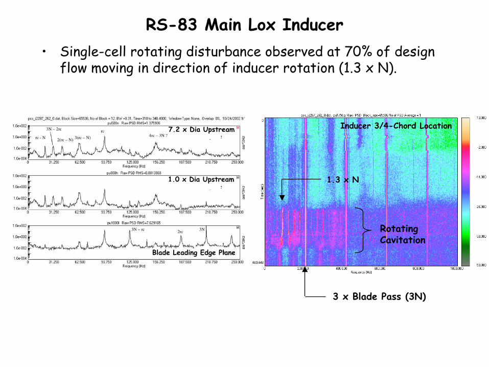
• Single-cell rotating disturbance observed at 70% of design flow moving in direction of inducer rotation (1.3 x N).
RS-83 Main Lox Inducer
3 x Blade Pass (3N)
Rotating Cavitation
Blade Leading Edge Plane
1.0 x Dia Upstream
7.2 x Dia Upstream Inducer 3/4-Chord Location
1.3 x N

• Inlet backflow and swirl captured on high-speed digital video.
RS-83 Main Lox Inducer
~ 1.8 x Dia Upstream of Leading Edge
FLOW
~ 4.1 x Dia Upstream of Leading Edge
Tufts on near pipe wall aligned with swirling backflow.
Frame Rate = 7000 fpsSpeed = 4200 rpm

• Objective: Directly measure inducer blade loads by miniature pressure transducers embedded in blades.
• Technology demonstrated in air turbine applications.• Water demonstration partially successful - performance
matched reference device but life limited by sealant failure.
Future
Turbine Blades with Embedded Transducers
Water Test Article with Transducers Embedded in Rotating Disk

• Objective: Revive Cal Tech’s dynamic pump test facility, replicate data, and establish institutional capability to measure pump dynamics - mass flow gain and cavitation compliance.
Future
Video courtesy of Dr. Christopher Brennen, California Institute of Technology

Test Team Members• Unsteady Data Analysis: Thomas Zoladz, Andrew Mulder• Facility Operation: James Aaron, Bo Jones, Doug McBride• Data Acquisition System Development: Joey Kirkpatrick,
Richard Norman, David Goodwin• Test Article Design: Dwight Goodman, John Forbes, Phyllis
Rabun, John Farrow