summary of the enerineerine geology .^ of the v^-j ... · summary of the engineering geology of the...
TRANSCRIPT
Summary of the Enerineerine.^ V^-J; %" '
Geology of theHarold D, Roberts Tunnel,Colorado
GEOLOGICAL SURVEY PROFESSIONAL PAPER 831-E

Summary of the EngineeringGeology of theHarold D. Roberts Tunnel,ColoradoBy ERNEST E. WAHLSTROM
ENGINEERING GEOLOGY OF THE HAROLD D. ROBERTS TUNNEL, COLORADO
GEOLOGICAL SURVEY PROFESSIONAL PAPER 831~E
A critical review and analysis of the application of geology during planning and construction of a major water tunnel in the Rocky Mountain West
UNITED STATES GOVERNMENT PRINTING OFFICE, WASHINGTON : 1981


PREFACE
This report is based on geologic investigations of the Harold D. Roberts Tunnel that were principally under the direction of Ernest E. Wahlstrom while consultant to the Denver Board of Water Commissioners. The scope of these investigations was probably the most extensive ever conducted on a major tunnel in the United States, and through the cooperation of Wahlstrom and Lawrence A. Warner and the Denver Board of Water Commissioners with the U.S. Geological Survey it has been possible to make the results of these investigations available to the general public. It is hoped that the results of these investigations and scientific research will aid others in investigations for construction of tunnels in the future.
The report was published as five separate chapters. Chapter A describes the history of the geologic investigations, the engineering design, and the construction methods. Chapter B describes the general geology of the tunnel site. Chapter C describes the engineering geology of the western part of the tunnel by geologic provinces from the West Portal through the Tertiary Montezuma Quartz Monzonite stock. Chapter D describes the engineering geology of the eastern part of the tunnel in the Precambrian rocks. Chapter E, this chapter, is the conclusion and gives a summary of the engineering geology in relation to the progress of driving the tunnel.

UNITED STATES DEPARTMENT OF THE INTERIOR
JAMES G. WATT, Secretary
GEOLOGICAL SURVEY
Doyle G. Frederick, Acting Director
Library of Congress Cataloging in Publication DataWahlstrom, Ernest Eugene, 1909-Summary of the engineering geology of the Harold D. Roberts Tunnel, Colorado.(Engineering geology of the Harold D. Roberts Tunnel, Colorado)(Geological Survey Professional Paper 831-E)Bibliography: p. 15Supt. of Docs.: I 19.16:831-E1. Harold D. Roberts Tunnel, Colo. 2. Engineering geology-Colorado-Summit Co. 3. Engineering geology-Colorado-
Park Co. I. Title II. Series. III. Series: United States Geological Survey Professional Paper 831-E. TA820.C6W35 624'.192*0978845 78-20808
For sale by the Superintendent of Documents, U.S. Government Printing Office Washington, D.C. 20402

CONTENTS
Page
Introduction ...................................................................... ElCritical review of preliminary geological investigations of the Roberts Tunnel ...... 2Correlation of surface geology with tunnel geology ................................. 3Correlation of supports, ground water, and feeler holes with tunnel geology ........ 5Relationship between geology and progress of construction ........................ 6Construction costs related to tunnel geology ....................................... gPrediction of tunnel geology from surface investigations ........................... 12
Reconnaissance investigations ................................................ 13Detailed investigations ........................................................ 14
References cited ................................................................... 15
ILLUSTRATIONS
[Plates are in pocket]
PagePLATE 1. Exposure map of surface over Harold D. Roberts Tunnel.
2. Section showing correlation of construction progress and gross geologic features, Harold D. Roberts Tunnel
FIGURE 1-6. Graphs showing progress:1. West Portal heading, January 1, 1957, through June 30, 1958 E82. West Portal heading, July 1, 1958, through December 31, 1959 93. Dillon heading, July 1, 1958, through January 2, 1960 ........ 104. Grant heading, July 1, 1958, through December 31, 1959 ...... 125. East Portal heading, February 19, 1957, through June 30, 1958 136. East Portal heading, July 1, 1958 through December 31, 1959 14
TABLES
Page
TABLE 1. Bedrock exposures and fracture correlations ............................2. Supported sections ............................ ... 3. Water-saturated sections that required grouting ........................4. Sections tested by feeler holes ......................... . 5. Summary of payment amounts from final estimate ....................6. Summary of some principal construction quantities .....................

ENGINEERING GEOLOGY OF THE HAROLD D. ROBERTS TUNNEL, COLORADO
SUMMARY OF THE ENGINEERING GEOLOGY OF THE HAROLD D. ROBERTS TUNNEL, COLORADO
By ERNEST E. WAHLSTROM
INTRODUCTION
Engineering geology is not an exact science, al though it employs many techniques that yield exact results. Geologic investigations prior to construction indisputably serve a valuable purpose, but there is widespread misunderstanding and even lack of know ledge of the objectives and methods of investigation, by both geologists and engineers. Ideally, an investi gation of a construction site should yield precise, three-dimensional locations of rock and soil units, locations and extent of fractures, quantitative ap praisals of the physical and chemical properties of the rock and soil units, and appraisal of the materi als in and near fractures or other rock or soil discontinuities. Estimates should be made of a- mounts and distribution of ground water or noxious gases, of rock or ground-water temperatures, and of the possibilities of seismic activity. Such data will permit adequate, economical engineering planning and design and will be of great practical value during construction. In actual practice, exact prediction of all the geologic conditions that will be encounted during construction almost never is realized, and the geologist should be given the opportunity to study and interpret for the engineer the geologic features revealed during construction and not anticipated in kind or degree during the site investigation.
Inadequate preliminary investigations may lead to geologic prognostication that is grossly in error, and that, under many circumstances, will result in poor engineering design and planning, and, in ex treme examples, in catastrophic failure of a struc ture. Inadequate preliminary investigations com monly result in construction costs far in excess of original estimates and in construction time sche dules that may be impossible to realize.
Optimum results from geological investigation of construction sites are obtained where the area to be occupied by a structure is small and accessible and
where the cost of the structure is high. In this situation, the cost and effort of a very detailed investigation is warranted by the nature of the project. Examples are damsites, foundations for bridge abutments, foundations for heavy buildings, shafts, or any kind of underground excavation of relatively small size. Less satisfactory results can be expected from investigations of engineering projects involving construction of features of great areal or linear extent, such as long canals or long tunnels that cross or penetrate a variety of geologic features of more or less complexity. Especially difficult is the prediction of detailed geologic conditions in tunnels in mountainous areas of high reliefer in long tunnels in unconsolidated glacial or fluvial materials in areas of low relief.
A characteristic limitation of tunnel investiga tions is that the expenditure of time and money that would be required to make a geological analysis as detailed as that for a small high-cost structure, such as a dam, is unreasonable, and the geologist and the engineer must accept the fact that many predictions and appraisals of the tunnel geology are based on long-range extrapolation or interpolation and the highly subjective interpretation of more or less in complete geologic data.
The Roberts Tunnel provides a case history of a major tunneling project where surface studies and detailed underground mapping provide data that give some indication of the extent to which prelimin ary geological investigations can be used to predict tunnel geology so as to permit adequate engineering design and cost estimates. This chapter reviews the history and validity of the geologic work in Roberts Tunnel and analyzes the general problems facing the engineering geologist assigned to a tunnel site investigation.
El

E2 ENGINEERING GEOLOGY OF THE HAROLD D. ROBERTS TUNNEL, COLORADO
CRITICAL REVIEW OFPRELIMINARY GEOLOGICAL INVESTIGATIONS
OF THE ROBERTS TUNNEL
The investigation of the dogleg route, along which the Roberts Tunnel eventually was constructed, was made in the summers of 1943 and 1944 to provide a general appraisal of the route in comparison with other possible or already proposed locations. Prior to 1943, investigations had advanced to the point where one tentative location had been rejected as unsatis factory after field study by T. S. Levering and E. B. Eckel. At the time of the 1943-44 investigation there was no assurance that the dogleg route would be adopted, and the geological study was regarded only as a reconnaissance survey to locate and broadly appraise the gross regional geological features. Five exploratory diamond drill holes in sections of known geological complexity and easy accessibility near the west end of the tunnel location and examination of several mine workings provided the only detailed information on actual subsurface conditions.
The Denver Board of Water Commissioners started excavation of the tunnel from the East Portal on a limited scale in 1946, but the final location of the tunnel was not determined with certainly until 1956, when funds for tunnel construction became avail able, and the responsibility for the final location and design of the tunnel was assigned to Tipton and Kalmbach, Inc. Four additional exploratory holes were drilled, and a detailed geologic map was made of the nearly 2 miles of tunnel already completed from the East Portal by the Board of Water Com missioners before the dogleg route was adopted. Because of the pressure of time and the great length of the tunnel, consideration could not be given to making a time-consuming detailed investigation along the entire route of the then-established tunnel line.
Estimates of the difficulty of tunneling, except for the west section of the tunnel, were of necessity based on the 1943-44 reconnaissance geological surveys over rugged topography in the vicinity of the Contin ental Divide and on the experience in the already completed portion of the tunnel. Cost extimates based on the available geological information proved to be somewhat unrealistic. The contract bid price, based on the contract specifications and estimates of quantities, exclusive of costs of engineering super vision, was $38,885,976.40. Actual construction costs (from 1956-60), exclusive of costs of engineering supervision and exclusive of costs prior to July 1956, were approximately $45,700,000, the difference being largely attributable to adverse unanticipated geo logic conditions encountered in the tunnel.
The Roberts Tunnel passes beneath a rugged, mountainous terrain of extreme geological complex ity. Extensive surface cover, relative inaccessibility of much of the tunnel area, and inclement weather for most of the year made detailed geologic mapping of surface geology arduous and time consuming. Elevations at the surface range from approximately 8,000 feet to more than 13,000 feet. Topographic features include shallow to deep valleys and canyons in a complicated drainage pattern cut into rocks of varying degrees of resistance to erosion. At higher elevations the valleys and canyons have been ex tensively scoured by alpine glaciers and at lower elevations they have been modified by deposition of erratically distributed glacial and fluvioglacial de posits and by accelerated erosion by flooding glacial melt waters. Bedrock includes a variety of Mesozoic sedimentary rocks, Precambrian and Tertiary meta- morphic rocks, and Precambrian and Tertiary intru sive rocks. Fractures are numerous and form compli cated intersecting patterns, and in the vicinity of the Colorado Front Range mineral belt are mineralized and accompanied by extensive hydrothermal alter ation. Ground water and noxious gases locally are concentrated in the fractures. There is no evidence of recent volcanic or seismic activity.
Curved or planar discontinuities of one kind or another in the rocks were the direct causes of most of the high costs of tunneling. Fissility in sedimentary rocks near the West Portal and, to a minor extent, layering in sedimentary rocks near the West Portal and layering in metamorphic rocks in the southeast leg of the tunnel influenced the amount of overbreak and the need for tunnel supports. Far more impor tant in impeding tunneling progress, however, were fractures that intersected the layered or unlayered rocks and that, in many sections of the tunnel, localized heavy, altered and (or) water-saturated ground. In retrospect, it is apparent that surface mapping of geologic units and projection to tunnel level was of less engineering significance than the attempt to estimate the numbers and distribution of faults and joints at depth, the amounts and distribution of ground water localized by the frac tures, and the intensities and kinds of rock altera tion associated with the fractures. The projec tion of rock units to tunnel level proved to be useful in fissile sedimentary rocks and to a limited extent in other rocks where there is a correlation between the brittleness and competency and the abundance of fractures and water content of the fractures. For example, quartzites in the Cretaceous Dakota Group were much more closely jointed and contained much more ground water than did shales and mudstones
SUMMARY E3
above and below the quartzites. Open, water-bearing fractures were more numerous in biotite-poor quartzo- feldspathic gneisses than in conspicuously foliated, mica-rich metamorphic rock.
Projection of rock units from the surface to tunnel level in the sedimentary rocks between the West Portal and station 165+00 proved to be generally successful, partly because of the presence of hogback exposures of layers resistant to weathering and erosion, and partly because of the shallow depth of the tunnel. For other sections of the tunnel where the tunnel intersected igneous and metamorphic rocks at considerable depths below the surface, projection of rock units from the surface to tunnel leVel was considerably less accurate. Fairly accurate pro jection of the Williams Range fault to tunnel level was possible because of information obtained from exploratory diamond drill holes and careful examin ation of the surface expression of the fault. For most of the tunnel, however, prediction of the nature and intensity of fracturing at tunnel level was based on examination of limited surface exposures, a few diamond drill holes, and purely subjective reasoning based on interpretation of the geological evolution of the general area.
It is almost axiomatic in geology that rocks that are inherently soft or rocks that have been exten sively fractured and (or) altered into soft or relatively incoherent masses are least likely to be exposed at the Earth's surface, so that prognostication of sub surface geology generally must be based on examin ation of exposures of relatively resistant rocks, inter pretation of topography, and appraisal of data from bore holes and geophysical surveys, if such data are available. That is, the features at the surf ace that are of maximum interest to the engineering geologist generally are the ones that are least visible, or they are completely buried by surface cover of one kind or another.
In the following pages the geology mapped at the surface is correlated with the tunnel geology, and an effort is made to appraise the various factors that should be considered in making geological projec tion from surface exposures to depth. From the West Portal to station 343+00, approximately, original investigations were sufficiently detailed to enable reasonably accurate prediction of the gross features of the geology at tunnel level (Wahlstrom, Robinson, and Hornback,1981). From station 343+00 to the East Portal (sta. 1238+58) original geological investiga tions were of a reconnaissance nature and were entirely inadequate (Warner and Robinson, 1981). Because of the interest created by the driving of the tunnel, additional mapping of the surface geology
above the tunnel was undertaken under the sponsor ship of the U.S. Geological Survey and the Univer sity of Colorado, and data of the kind that would have been obtained during an adequate original program of geological investigations are now avail able (Robinson, Warner, and Wahlstrom, 1974). Dis cussion of the correlation of surface and under ground features between station 343+00 and the East Portal is based on the assumption that the detailed surface mapping had been completed before the tunnel was designed instead of after its completion. This method of analysis permits a balanced presen tation that assumes careful preliminary geological investigation over the entire length of the tunnel. Surface geologic features from approximately sta tion 343+00 to station 468+50 were taken from maps prepared by George E. Ulrich (1963) of the University of Colorado and from station 468+50 to the East Portal from maps prepared by Charles S. Robinson of the U.S. Geological Survey (Robinson, Warner, and Wahlstrom, 1974).
Geophysical investigations over the tunnel line were considered at several stages in the preliminary investigations, but the complexity of the geologic structure and, for portions of the tunnel, the great depth below the surface led to the conclusion that the kinds of information that would be of value in interpreting details of tunnel geology could not be obtained by any known methods of geophysical exploration.
CORRELATION OF SURFACE GEOLOGY WITH TUNNEL GEOLOGY
As has been pointed out in previous sections, fractures of various kinds and magnitudes, especial ly where they are accompanied by wallrock alter ation, ground water, or gas, produced the most difficult tunneling conditions in the Roberts Tunnel. Original structures in the rock and the composition of the rock were of less consequence. In an area such as the one in the vicinity, of the Roberts Tunnel, surface geologic mapping of and attempted pro jection to the tunnel level of fault and joint systems, and estimation of the extent to which the fractures have localized ground water concentrations and are attended by undesirable kinds of wallrock alteration, all have considerably more engineering value than projection to tunnel level of the various rock units exposed at the surface. Accordingly, in the following analysis, emphasis is placed on the correlation of the numbers of and kinds of fractures observed at the surface with the fractures noted during underground mapping of the tunnel.

E4 ENGINEERING GEOLOGY OF THE HAROLD D. ROBERTS TUNNEL, COLORADO
Plate 1 shows the areas of numerous bedrock exposures that were located during the mapping of the surface geology above the Roberts Tunnel. Each of the areas contains enough exposed bedrock to permit a fairly accurate appraisal of its composition and structure. Areas where bedrock is not exposed are covered by soil, stream alluvium, glacial de posits, landslides, talus, thick vegetation, or moun- taintop debris. In areas that are not covered by transported overburden, the composition of bedrock and the location of approximate contacts between different kinds of rock generally could be determined by mapping the distribution of material derived from weathering of the bedrock, but direct examination of fractures, folds, or original structures in the rocks generally was not possible. For each of the areas of numerous bedrock exposures, an estimate was made of the percent of actual bedrock exposed, an estimate that is highly subjective and that may be consider ably in error.
Joints presented a special problem during geological mapping of the surface over the Roberts Tunnel. As would be expected, the most closely jointed rocks in the tunnel generally were covered at the surface, and so examination of surf ace exposures generally gave an indication of the nature of only the least jointed rocks. Many joints at the surface were formed by or were emphasized by surficial processes associated with weathering, mass wasting, and glaciation and were distinguished with difficulty from persistent joints formed by movements or volume changes in the rocks at depth. In the tunnel many rocks containing joints with rough surfaces presented no difficulty in the tunneling operation. Other rocks in which the joints were smooth or contained clay minerals easily caved into the tunnel. However, examination of joints at the surface generally gave no significant clues as to the probably nature of the joint surfaces at depth.
Because of the scale of the surface maps and time limitations, counting and mapping of all prominent joints at the surface was impractical. As a general procedure, sets of joints were indicated by a few joint symbols on the maps, and notebook notations were made of the spacing and attitudes of the joints. In brittle rocks, such as the quartzite in the Dakota and the baked shale in the Pierre west of the Montezuma stock, joints are so numerous and of such diverse origins and attitudes that individual attitudes re corded on the maps were of little significance. Gen erally, brittle rocks that are closely jointed in surface exposures also are closely jointed at tunnel level.
Table 1 contains a numerical summary of pertin ent data extracted from plate 1 and from geologic maps of the tunnel. Areas were determined by plani-
metric measurements. Exposures on steep slopes actually provided more area for field examination than is measured by the planimeter, but no attempt was made to make slope corrections because the accuracy of projection of surface geology to tunnel level in areas of rugged topography or great distance above tunnel level is not appreciably increased by taking into consideration the total area exposed on slopes at the surface.
Plate 1 and table 1 indicate the difficulty of predicting fracture spacing at tunnel level by means of surface investigations in extensively covered areas. Evaluation of the data shows that the prediction of the spacing and magnitudes of faults and estimation of the numbers and attitudes of joints are of necessity largely subjective and would have to be based, to a considerable extent, on interpretation of the geologi cal evolution of the area and interpretation of the genesis and significance of surface topographic fea tures. Table 1 does not include any consideration of the kind and intensity of rock alteration associated with the fractures or any evaluation of groundwater conditions. Nine exploratory drill holes between stations 192+40 and 459+35 yielded some information as to the nature but not the extent of rock alteration for a limited portion of the tunnel. Elsewhere, the great depth of the tunnel below the surface made exploratory drilling impractical, and prediction of alteration at tunnel level was based on scattered bedrock exposures at the surface and examination of mine dumps and underground workings.
In retrospect, the accuracy with which gross geo logical conditions in the Roberts Tunnel were pre dicted was good considering the fragmentary nature of data collected at the surface during original investigations. Detailed mapping at the surface over the east leg of the tunnel after the tunnel was completed revealed many features that were over looked or not recorded in the original reconnaissance investigations. If detailed mapping of the surface geology had preceded tunnel construction, predic tion of gross features of tunnel geology could have been made with more assurance of accuracy. But because of the depth of the tunnel and the complexity of the geologic structure, it is unlikely that the accuracy of prediction of small details of under ground structure could have been appreciably im proved. In table 1 the ratios of the numbers of faults mapped at the surface to faults 1 foot or more in width in the tunnel are particularly revealing. Pre sumably, most prominent faults at the surface would be observable in areas of numerous bedrock ex posures or where topographic expression is distinc tive, and, because they are prominent faults, projec tion for considerable distances laterally or vertically

SUMMARY
TABLE I. Bedrock exposures and fracture correlations in the Roberts Tunnel
E5
Stations
9+46 (West Portal)to 180+00
180+00 to 291+60
291+60 to 343+00
343+00 to 689+50
689+50 to 977+00
977+00 to 1238+58(East Portal)
9+46 to 1238+58
A
1,0900
1,020550
690550
4,290540
4,4501,250
2,3600
4,450
B
3.84
2.12
0.82
10.54
10.69
8.68
36.69
C
10.9
3.3
16.7
17.6
14.4
8.6
13.1
D
6.7
1.9
8.6
6.4
5.7
2.4
5.1
E
13
4
13
85
30
11
156
F
62
41
15
111
32
39
300
G
688
1,037
189
1,420
376
196
3,906
H
24.8
10.7
27.2
24.4
76.5
133.5
31.47
I
1,292
None
312
2,372
908
421
5,305
J
13.2
16.5
14.6
31.7
62.1
21.1
K
12
None
2
13
15
8
50
L
0.19
0
.13
.12
.47
.20
.17
M
0.02
0
.01
.09
.04
.04
.01
N
6.9
2.3
21.2
7.4
8.8
1.4
6.5
Remarks
Sedimentary rocks below Williams Rangethrust fault.
Highly fractured rocksabove WilliamsRange thrust fault.
Baked shale belowWilliams Rangethrust fault and westof Montezuma stock.
Montezuma stock at tunnel level.
Precambrian gneiss andgranite.
Precambrian gneiss,migmatite, andgranite.
A. Maximum and minimum depth of tunnel below surface along tunnel line, in feet. I.B. Total area mapped at surface, in square miles. J.C. Percent of mapped area containing numerous bedrock exposures. K.D. Estimated percent of mapped area containing actual bedrock exposures.E. Number of faults and veins mapped at surface. L.F. Number of prominent faults and veins, 1 foot or more in width, mapped at tunnel
level. M. G. Total number of faults and veins mapped at tunnel level. H. Average spacing of faults (and veins) in tunnel, in feet. N.
Number of prominent joints mapped at tunnel level.Average spacing of strong joints in tunnel, in feet.Number of faults (and veins) observed to intersect or projected to intersection with
tunnel line at surface. Ratio (K/F) of mapped or projected faults (and veins) at surface above tunnel to
strong faults (and veins) mapped at tunnel level. Ratio (K/G) of mapped or projected faults (and veins) at surface above tunnel to
all faults (and veins) mapped at tunnel level. Estimated percent of bedrock exposed at surface along a line directly above
tunnel.
should have some validity. Because of extensive cover of one kind or another over the Roberts Tunnel, however, a very small number of the prominent faults were noted in bedrock at the surface as compared with the large number of prominent faults observed in the tunnel.
CORRELATION OF SUPPORTS,GROUND WATER, AND FEELER HOLES
WITH TUNNEL GEOLOGY
Table 2 correlates the percent of steel and timber support with rock types in various geologic units in the Roberts Tunnel. The data show that fractures, locally accompanied by alteration and ground water, were the primary factors in determining the need for support except in the fissile shaly sedimentary rocks between stations 43+14 and 180+00. With the ex ception of the shaly rocks, all the rock types in the Roberts Tunnel, in the absence of fractures of one kind or another, and (or) the alteration and ground water associated with the fractures, would have been sufficiently competent to stand in the tunnel without
support. A possible exception is popping rock locally encountered in the East Portal heading, but even here the stresses in the rock probably are related to structural inhomogeneities in the rocks resulting from fault dislocations and local accumulations of unbalanced stresses.
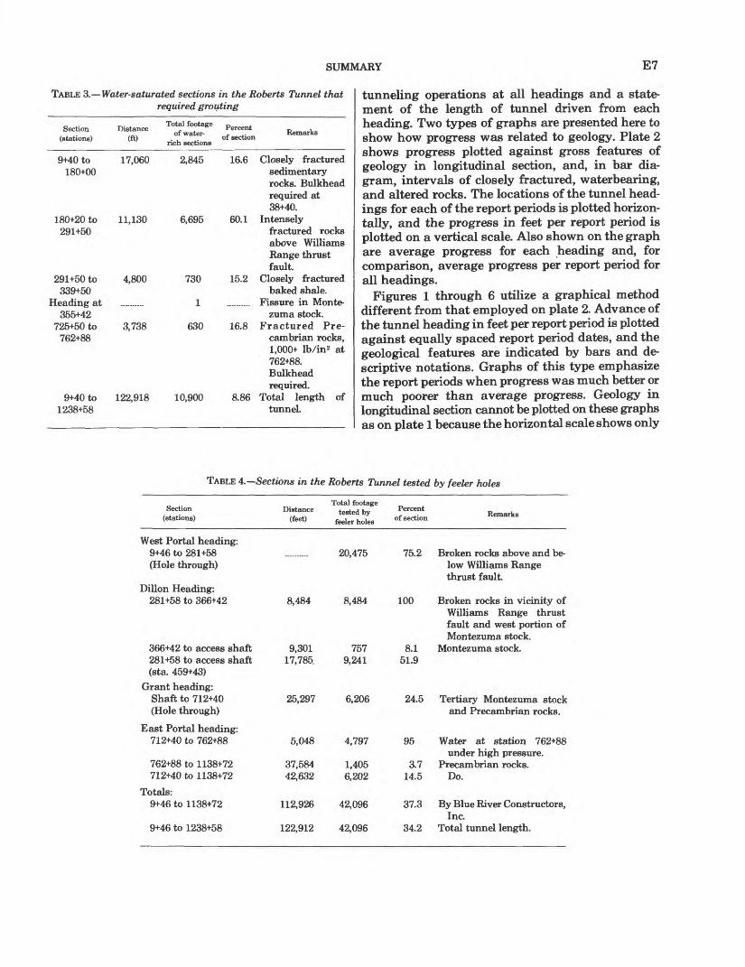
Table 3 summarizes the relationship between rock types and ground water. Maximum amounts of ground water occurred in shallow, highly fractured rocks with the exception of high-pressure water flows associated with fractures in the interval between stations 725+50.and 762+88, where the tunnel is 2,200-4,400 feet below the surface. There is no defin ite correlation between rock type and amount of water, except in the brittle quartzite of the Dakota Group, which retains open fractures, and in the shaly sedimentary rocks, where open fractures tend to close by plastic flow of the rocks under load. Elsewhere, argillic alteration and gouge tended to prevent ground water penetration along fractures. Table 4 summarizes feeler hole operations and indi cates the percent of the tunnel explored by drill holes in the headings for various portions of the tunnel.

E6 ENGINEERING GEOLOGY OF THE HAROLD D. ROBERTS TUNNEL, COLORADO
TABLE 2. Supported sections in the Roberts Tunnel
Section (stations)
9+46 (West Portal)to 43+14
43+14 to 180+20
180+20 to 291+50
291+50 to 339+75
339+75 to 347+50
347+50 to 625+00
625+00 to 636+85
636+85 to 686+50
686+50 to 886+20
886+20 to 977+00
977+00 to 1084+00
1084+00 to 1187+50
1187+50 to 1238+58 (East Portal)
1138+72 to 1238+58
Supported (percent)
Remarks
75.5 Unsupported sections in quartzite of theDakota Group only. Rocks closely fractured.
100 Sedimentary rocks below Williams Rangethrust fault. Mostly shales, limy shales, andsandy shales. Locally fractured.
100 Intensely fractured schist, gneiss, migmatite,pegmatite, and aplite in plate above WilliamsRange thrust fault.
100 Closely fractured baked shale below WilliamsRange-thrust fault and west of Montezumastock.
60.9 Jointed, mixed quartz monzonite and bakedshale in border zone of Montezuma stock.
88 Closely fractured and locally altered quartzmonzonite in Montezuma stock.
58.6 Roof pendant of gneiss in Montezuma stock.Locally jointed.
72.4 Fractured and locally altered quartz monzonitein Montezuma stock.
69.9 Locally fractured schist, gneiss, and quartzitewith minor aplite, pegmatite, and granite.
52.3 Boulder Creek Granite (granodiorite) withinclusions of metamorphic rocks. Locallyfractured.
48.9 Schist and gneiss with minor aplite, pegma tite, and granite. Locally fractured.
24 Silver Plume Granite with numerous inclu sions of schist, gneiss, and quartzite. Minorfractures.
7.3 Schist, gneiss, quartzite, and lime-silicaterocks injected by granite and pegmatite.Minor fractures.
16.7 Denver Water Board section. Gneiss, schist,migmatite, and lime-silicate rocks. Minorfractures.
Feeler holes were drilled where experience in the tunnel indicated the probability of adverse con ditions, especially ground water, beyond the tunnel heading. The feeler holes were also used to grout off waterflows.
RELATIONSHIP BETWEEN GEOLOGY AND PROGRESS OF CONSTRUCTION
An informative method of appraising the effects of adverse geological conditions in tunneling costs is the graphical correlation on charts of progress of the tunneling operation with the geologic conditions encountered in the tunnel. Slow progress because of adverse geological conditions is directly proportion al to high costs per foot of tunnel. If it had been possible to quantitatively appraise the geology for
the entire length of the tunnel during preliminary investigations, progress and anticipated costs of driving the tunnel in various geologically different sections of the tunnel could have been plotted on prediction charts that would have closely resembled the charts plotted after completion of the tunnel and would represent the ultimate in attainment of the purposes of the geological investigation. The dif ferences between predicted progress and cost charts and the charts prepared after completion of the tunnel represent the magnitude of the uncertainties that attend geological investigations over the sur face of tunnel, especially in a region of rugged topography and extensive surface cover.
Progress in the Roberts Tunnel was summarized in "Progress Report" prepared on the 15th and last day of each month. The reports included a summary of
SUMMARY E7
TABLE 3. Water-saturated sections in the Roberts Tunnel that required grouting
Section Distance (stations) (ft)
Total footageof water-
rich sections
Percent of section
Remarks
9+40 to 180+00
180+20 to 291+50
291+50 to339+50
Heading at355+42
725+50 to 762+88
9+40 to 1238+58
17,060
11,130
4,800
3,738
2,845
6,695
730
1
630
122,918 10,900
16.6 Closely fractured sedimentary rocks. Bulkhead required at 38+40.
60.1 Intenselyfractured rocks above Williams Range thrust fault
15.2 Closely fracturedbaked shale.
.......... Fissure in Monte-zuma stock.
16.8 Fractured Pre- cambrian rocks, 1,000+ lb/in2 at 762+88. Bulkhead required.
8.86 Total length of tunnel.
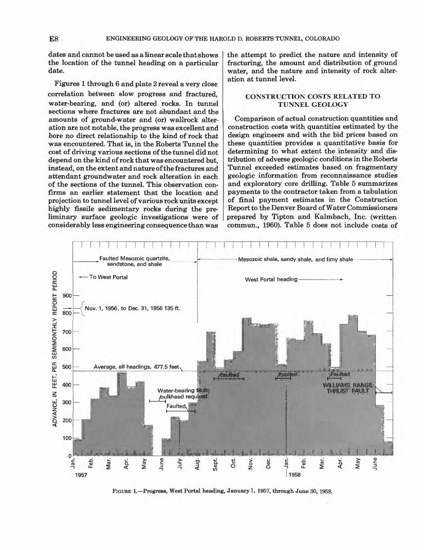
tunneling operations at all headings and a state ment of the length of tunnel driven from each heading. Two types of graphs are presented here to show how progress was related to geology. Plate 2 shows progress plotted against gross features of geology in longitudinal section, and, in bar dia gram, intervals of closely fractured, waterbearing, and altered rocks. The locations of the tunnel head ings for each of the report periods is plotted horizon tally, and the progress in feet per report period is plotted on a vertical scale. Also shown on the graph are average progress for each heading and, for comparison, average progress per report period for all headings.
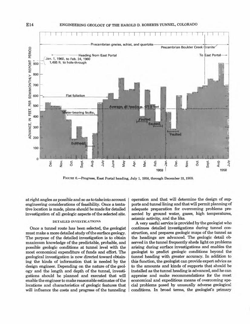
Figures 1 through 6 utilize a graphical method different from that employed on plate 2. Advance of the tunnel heading in feet per report period is plotted against equally spaced report period dates, and the geological features are indicated by bars and de scriptive notations. Graphs of this type emphasize the report periods when progress was much better or much poorer than average progress. Geology in longitudinal section cannot be plotted on these graphs as on plate 1 because the horizontal scale shows only
TABLE 4. Sections in the Roberts Tunnel tested by feeler holes
Section (stations)
Distance (feet)
Total footagetested by
feeler holes
Percent of section Remarks
West Portal heading: 9+46 to 281+58 .......... 20,475(Hole through)
Dillon Heading: 281+58 to 366+42 8,484 8,484
9,301 75717,785, 9,241
25,297 6,206
366+42 to access shaft 281+58 to access shaft (sta. 459+43)
Grant heading: Shaft to 712+40 (Hole through)
East Portal heading: 712+40 to 762+88 5,048 4,797
762+88 to 1138+72 37,584 1,405 712+40 to 1138+72 42,632 6,202
Totals: 9+46 to 1138+72 112,926 42,096
9+46 to 1238+58 122,912 42,096
75.2
100
8.1 51.9
24.5
95
Broken rocks above and be low Williams Range thrust fault.
Broken rocks in vicinity of Williams Range thrust fault and west portion of Montezuma stock.
Montezuma stock.
Tertiary Montezuma stock and Precambrian rocks.
Water at station 762+88under high pressure.
3.7 Precambrian rocks. 14.5 Do.
37.3 By Blue River Constructors,Inc.
34.2 Total tunnel length.
E8 ENGINEERING GEOLOGY OF THE HAROLD D. ROBERTS TUNNEL, COLORADO
dates and cannot be used as a linear scale that shows the location of the tunnel heading on a particular date.
Figures 1 through 6 and plate 2 reveal a very close correlation between slow progress and fractured, water-bearing, and (or) altered rocks. In tunnel sections where fractures are not abundant and the amounts of ground-water and (or) wallrock alter ation are not notable, the progress was excellent and bore no direct relationship to the kind of rock that was encountered. That is, in the Roberts Tunnel the cost of driving various sections of the tunnel did not depend on the kind of rock that was encountered but, instead, on the extent and nature of the fractures and attendant groundwater and rock alteration in each of the sections of the tunnel. This observation con firms an earlier statement that the location and projection to tunnel level of various rock units except highly fissile sedimentary rocks during the pre liminary surface geologic investigations were of considerably less engineering consequence than was
the attempt to predict the nature and intensity of fracturing, the amount and distribution of ground water, and the nature and intensity of rock alter ation at tunnel level.
CONSTRUCTION COSTS RELATED TO TUNNEL GEOLOGY
Comparison of actual construction quantities and construction costs with quantities estimated by the design engineers and with the bid prices based on these quantities provides a quantitative basis for determining to what extent the intensity and dis tribution of adverse geologic conditions in the Roberts Tunnel exceeded estimates based on fragmentary geologic information from reconnaissance studies and exploratory core drilling. Table 5 summarizes payments to the contractor taken from a tabulation of final payment estimates in the Construction Report to the Denver Board of Water Commissioners prepared by Tipton and Kalmbach, Inc. (written commun., 1960). Table 5 does not include costs of
1957 1958
FIGURE 1. Progress, West Portal heading, January 1, 1957, through June 30, 1958.
SUMMARY E9
planning and investigation, design, engineering supervision, or other costs.
Table 6 summarizes some of the principal con struction quantities and costs. Items were selected for tabulation that most significantly indicate the manner in which quantities and costs exceeded the original estimates and bid prices because of adverse geologic conditions. Increased tunnel excavation was required to provide room for installation of tunnel supports. In Schedule I adverse geological conditions were expected, but an increase of 64.59 percent for steel supports and of 65.23 percent for timber supports reflects the need for far more support than was anticipated for the portion of the tunnel in the Montezuma stock. In Schedule II extrapolation of the conditions existing in the tunnel driven by the Denver Water Board and lack of adequate infor mation based on surface geology resulted in an estimate of quantities that was far too low. In Schedule II the overrun on steel supports was 147.39 percent and on timber supports 247.05 percent, and, again, is attributed to the presence of several inter
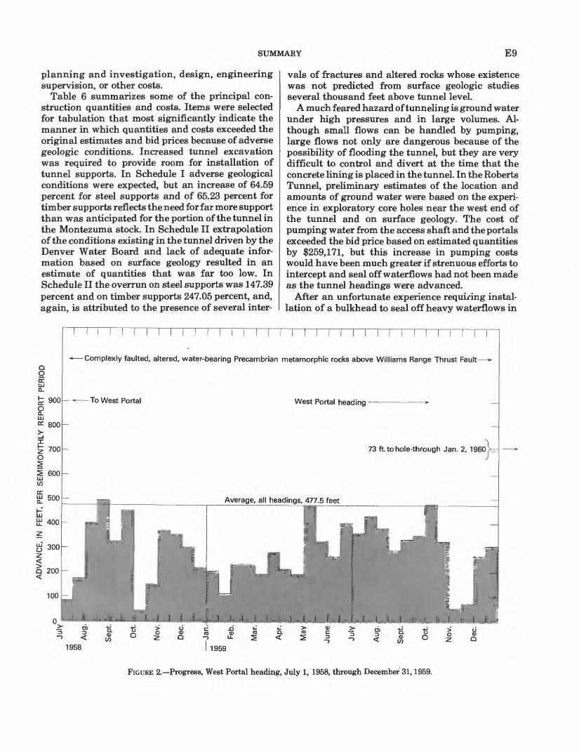
vals of fractures and altered rocks whose existence was not predicted from surface geologic studies several thousand feet above tunnel level.
A much feared hazard of tunneling is ground water under high pressures and in large volumes. Al though small flows can be handled by pumping, large flows not only are dangerous because of the possibility of flooding the tunnel, but they are very difficult to control and divert at the time that the concrete lining is placed in the tunnel. In the Roberts Tunnel, preliminary estimates of the location and amounts of ground water were based on the experi ence in exploratory core holes near the west end of the tunnel and on surface geology. The cost of pumping water from the access shaft and the portals exceeded the bid price based on estimated quantities by $259,171, but this increase in pumping costs would have been much greater if strenuous efforts to intercept and seal off waterflows had not been made as the tunnel headings were advanced.
After an unfortunate experience requiring instal lation of a bulkhead to seal off heavy waterflows in
CO1958 1959
FIGURE 2. Progress, West Portal heading, July 1, 1958, through December 31,1959.
E10 ENGINEERING GEOLOGY OF THE HAROLD D. ROBERTS TUNNEL, COLORADO
TABLE 5. Summary of payment amounts from final estimate, Roberts Tunnel
Schedule I (West Portal to station 740+00)Contract items ........ .................... $31,526,463.09Less contract deduction percent ............ 1,176,882.87Net earned for contract items ............ 30,349,580.22Change orders, total ....................... 94,124.76
Total earned .......................... 30,443,704.98Original bid price ..... .................... 26,905,380.00
Schedule II (station 740+00 to East Portal) Contract items ........Less contract deduction of 3.733 percent
Net earned for contract items .........Change orders, total ... .................
Total earned ......................Original bid price ......................
15,553,684.79580,619.05
14,973,065.74291,306.09
15,264,371.8313,488,500.00
Total contract payment estimate . Total original bid ..... ...........
45,708,076.8140,393,880.00
the quartzite of the Dakota Group near the West Portal, many more feeler holes were drilled than were envisioned in the plans and specifications. The engineer's esti mate anticipated that 33,000 lineal feet of feeler holes might be drilled in all headings, but upon completion of the tunnel a total of 417,064 feet had been drilled in an effort to locate undesirable conditions beyond the tunnel headings. In a fairly successful attempt to seal off waterflows encountered in the feeler holes, a total of 6,143.23 cubic yards of grout costing $1,222,647 was pumped at high pressure into water-bearing rocks beyond the tunnel headings. The bid price for grouting, on the basis of the engineer's estimates, was $220,000.
Quantities and costs of placing concrete lining in the tunnel exceeded original estimates because of the necessity of excavating a larger tunnel cross section where steel supports were installed. Concrete placed outside of paylines at the contractor's expense totaled 74,339 cubic yards, and indicates an average overbreak for the entire tunnel of 28.25 percent. If the
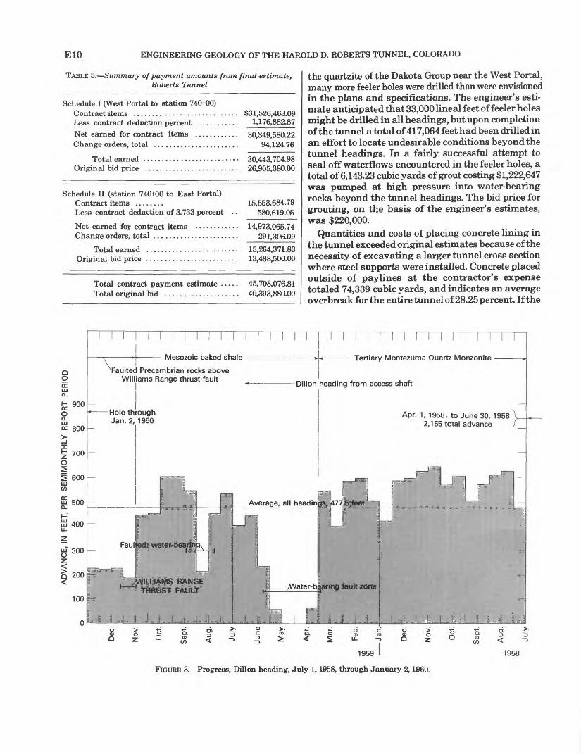
Mesozoic baked shale
o O ccLJJ Q_
fe 900
2LJJcc 800
_i
^ 700 O
I 600LJJ
£ 500D_
a 400U_
uj 300
0 200
100
^Faulted Precambrian rocks above Williams Range thrust fault
Hole-through Jan. 2, 1960
Tertiary Montezuma Quartz Monzonite
Dillon heading from access shaft
Apr. 1, 1958, to June 30, 1958 2,155 total advance
1959 1958
FIGURE 3. Progress, Dillon heading, July 1,1958, through January 2,1960.

SUMMARY
TABLE 6. Summary of some principal construction quantities, Roberts Tunnel
Ell
Item Engineer's estimate Actual Percent increase Unit bid price Total bid price Payment amount (final estimate)
Excavation (within pay lines)1
Excavation unclassi fied in tunnel (in
Steel tunnel supports
Timber tunnel sup ports (in millions of board feet measure)
Pumping water through shafts and portals (in million's of gallons) .......
Drilling feeler holes and high-pressure grout holes (in
Grouting through high-pressure grout holes (in cubic
2373,000 yds3 3 190,000 yds3
27,200,000 Ibs 31,350,000 Ibs
21,600 M bm 3 300 M bm
1,900 M gal (access shaft)
1,400 M gal (West Portal)
200 M gal (East Portal)
233,00aiinft 33,000 lin ft
2900 yds3 3200 yds3
391,700.77 yd3 203,968.29 yd3
11,850,630 Ibs 3,339,741 Ibs
2,643 M bm 1,041 M bm
Water dispoe
1,395.437 Mgal
2,324.213 Mgal
501.746 M gal
199,028.5 lin ft 18,035.5 lin ft
6,032.69yd 3 110.545yd3
5.01 7.35
64.59 147.39
65.23 249.05
$38.38 43.85
.22
.24
500.00 500.00
$14,315,740 8,331,500
1,584,000 324,000
800,000 150,000
$15,033,475 8,944,009
2,607,138 801,537
1,321,855 520,578
ial, feeler holes, and grouting4
-26.55
+66.01
+150.87
+503.11 +501.18
+570.30 -44.72
$150.00
110.00
110.00
4.00 4.00
200.00 200.00
$285,000
154,000
22,000
132,000 12,000
180,000 40,000
$209,315
255,663
55,192
796,114 72,142
1,206,53# 22,109
Concrete lining in tunnel5
Tunnel excavated bycontractor (in cubicyards) ............ 2 150,000 yds3 161,284 yds3 7.52
Tunnel excavated byDenver WaterBoard (in cubicyards) ............ 319,200 yds3 22,337 yds3 16.34
Tunnel excavated bycontractor (in cubicyards) ............ 368,000yds3 79,500yds3 16.17
$35.00
30-00
35.00
$5,250,000
576,000
2,380,000
$5,644,945
670,117
2,782,523
'All quantities exclusive of 9,992 ft of existing tunnel. Change order for resetting tunnel supports and trimming tights in existing excavated tunnel cost $274,714. Resetting supports and trimming tights more than 50 ft behind heading not covered in contract specifications, and resulted mainly from slow swelling and squeezing of altered rock in the Montezuma stock.
"Schedule I: Construction from West Portal and access shaft to station 740+00."Schedule II: Construction from station 740+00 to East Portal
'26,620 linear feet of tile drains and 851 cubic yards of gravel drains installed below invert to divert water not sealed off by grouting.
'Total of 440,539 barrels of Portland cement used in all concrete structures. Concrete placed outside of paylines in tunnel was 74,339 cubic yards, corresponding to a concrete overbreak of 28.25 percent. Total concrete placed in tunnel inside paylines was 263,122 cubic yards.
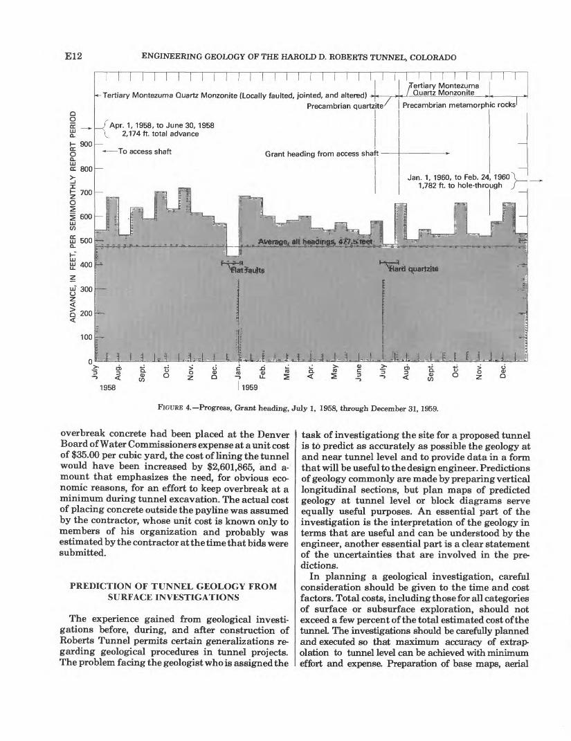
E12 ENGINEERING GEOLOGY OF THE HAROLD D. ROBERTS TUNNEL, COLORADO
Tertiary Montezuma Quartz Monzonite (Locally faulted, jointed, and altered) *
ccLUa.
900
800
700
600
500
400
300
200
100
0
/Apr. 1, 1958, to June 30, 1958 V_ 2,174 ft. total advance
To access shaft
Precambrian quartzite
Grant heading from access shaft
/Tertiary Montezuma Quartz Monzonite
Precambrian metamorphic rocks 1
Jan. 1, 1960, to Feb. 24, 1960 1,782 ft. to hole-through
Li JL J J J..Q. 0)c/i
.00) Q.
<
o><
1958
Q. 0)c/i
1959
FIGURE 4. Progress, Grant heading, July 1, 1958, through December 31, 1959.
overbreak concrete had been placed at the Denver Board of Water Commissioners expense at a unit cost of $35.00 per cubic yard, the cost of lining the tunnel would have been increased by $2,601,865, and a- mount that emphasizes the need, for obvious eco nomic reasons, for an effort to keep overbreak at a minimum during tunnel excavation. The actual cost of placing concrete outside the payline was assumed by the contractor, whose unit cost is known only to members of his organization and probably was estimated by the contractor at the time that bids were submitted.
PREDICTION OF TUNNEL GEOLOGY FROM SURFACE INVESTIGATIONS
The experience gained from geological investi gations before, during, and after construction of Roberts Tunnel permits certain generalizations re garding geological procedures in tunnel projects. The problem facing the geologist who is assigned the
task of investigationg the site for a proposed tunnel is to predict as accurately as possible the geology at and near tunnel level and to provide data in a form that will be useful to the design engineer. Predictions of geology commonly are made by preparing vertical longitudinal sections, but plan maps of predicted geology at tunnel level or block diagrams serve equally useful purposes. An essential part of the investigation is the interpretation of the geology in terms that are useful and can be understood by the engineer, another essential part is a clear statement of the uncertainties that are involved in the pre dictions.
In planning a geological investigation, careful consideration should be given to the time and cost factors. Total costs, including those for all categories of surface or subsurface exploration, should not exceed a few percent of the total estimated cost of the tunnel. The investigations should be carefully planned and executed so that maximum accuracy of extrap olation to tunnel level can be achieved with minimum effort and expense. Preparation of base maps, aerial

SUMMARY E13
Lrecambrian Boulder Creek Granite
Precambrian gneiss, schist, and migmatite /containing small granite bodies___
/Precambrian Silver Plume Granite containing quartzite inclusions
1958
FIGURE 5. Progress, East Portal heading, February 19,1957, through June 30,1958.
1957
photographs, triangulation controls, surveyed lines, control points, and the like should be regarded as engineering functions and should not be included in costs of geological investigations. In contrast, per formance or supervision of geological mapping, geo physical work, soil and rock testing, petrographic work, chemical analysis, diamond drilling, or sinking of exploratory shafts or driving of exploratory tunnels legitimately are the geologists' responsibilities.
RECONNAISSANCE INVESTIGATIONS
In the initial stages of planning a project, including construction of one or more tunnels, the geologist may be asked to compare the merits of several alternate locations by making reconnaissance studies of the geology of the general area of interest. Such studies are based on existing geologic maps or, in the absence of these, on expeditious determination of the gross aspects of the geology. Efforts are made to locate and to evaluate features, such as unconsolidated surficial deposits, faults with large displacement, crush zones,
deeply weathered rock, mineralized or otherwise altered rocks of uncertain behavior, soft squeezing or swelling ground, and to estimate the amounts and distribution of ground water or noxious gases in the rocks. Interpre tation of bedrock and surficial geology may of necessity be based largely on studies of the characteristics of geomorphic features recognized in the field or in aerial photographs or topographic maps. In areas of exten sive surface cover, long, straight valleys or canyons may indicate buried planar zones of weakness. Aerial photographs may reveal a systematic pattern of frac tures that is not evident on the ground. Other topo graphic features may indicate the composition and origin of bedrock and can be checked by field examin ation. In any event, the geologist after such a study should be prepared to recommend one or more particu lar locations where the tunnel or tunnels will intersect the least number of potentially adverse underground conditions. If, as is generally the case, undesirable geologic conditions cannot be entirely avoided in any tunnel location, tunnel lines should be chosen so as to cross features, such as faults and crush zones, as nearly
E14 ENGINEERING GEOLOGY OF THE HAROLD D. ROBERTS TUNNEL, COLORADO
Precambrian Boulder Creek GraniteQgccLLJ 0.
cc O0.LU CC
Precambrian gneiss, schist, and quartzite
900
/Jan. 1, 1960, to Feb. 24, 1960 Z\ 1,485 ft. to hole-through
Heading from East Portal
1959 1958
FIGURE 6. Progress, East Portal heading, July 1, 1958, through December 31,1959.
at right angles as possible and so as to take into account engineering considerations of feasibility. Once a tenta tive location is made, plans should be made for detailed investigation of all geologic aspects of the selected site.
DETAILED INVESTIGATIONS
Once a tunnel route has been selected, the geologist must make a more detailed study of the surface geology. The purpose of the detailed investigation is to obtain maximum knowledge of the predictable, probable, and possible geologic conditions at tunnel level with the most economical expenditure of funds and effort. The geological investigation is now directed toward obtain ing the kinds of information that is needed by the design engineer. Depending on the nature of the geol ogy and the length and depth of the tunnel, investi gations should be planned and executed that will enable the engineer to make reasonable estimates of the locations and characteristics of geologic features that will influence the costs and progress of the tunneling
operation and that will determine the design of sup ports and tunnel lining and that will permit planning of adequate preparation for overcoming problems pre sented by ground water, gases, high temperatures, seismic activity, and the like.
A very useful service is provided by the geologist who continues detailed investigations during tunnel con struction, and prepares geologic maps of the tunnel as the headings are advanced. The geologic detail ob served in the tunnel frequently sheds light on problems arising during surface investigations and enables the geologist to predict geologic conditions beyond the tunnel heading with greater accuracy. In addition to this function, the geologist can provide expert advice as to the amounts and kinds of supports that should be installed as the tunnel heading is advanced, and he can appraise and make recommendations for the most economical and expeditious means of overcoming spe cial problems posed by unusually adverse geological conditions. In broad terms, the geologist's primary
SUMMARY E15
purpose is to insure the day-to-day and the long range safe and economical advance of the tunnel heading by careful consideration of the details of tunnel geology and correlation with aspects of the geology determined during preliminary investigations.
Geological records of tunneling operations should be compiled, appraised, and placed where they can be reviewed by interested persons. Accumulated experi ence in a variety of tunneling projects is needed, and continued reappraisal of the problems of tunnel geology based on growing accumulations of data will permit increasingly objective planning and engineering of tunneling projects.
REFERENCES CITED
Robinson, C. S., Warner, L. A., and Wahlstrom, E. E.,1974, General Geology of the Harold D. Roberts Tunnel, Colorado: U.S. Geol. Survey Prof. Paper 831-B, 48 p.
Ulrich, G. E., 1963, Petrology and structure of the Porcupine Mountain area, Summit County, Colorado: Boulder, Colorado Univ. unpub. Ph. D. thesis, 205 p.
Wahlstrom, E. E., Robinson, C. S., and Hornback, V. Q., 1981, Geology of the western part of the Harold D. Roberts Tunnel, Colorado (stations 0+00 to 690+00): U.S. Geol. Survey Prof. Paper 831-C, 58 p.
Warner, L.A., and Robinson, C. S., 1981, Geology of the eastern part of the Harold D. Roberts Tunnel, Colorado (stations 690+00 to 1230+58): U.S. Geol. Survey Prof. Paper 831-D, 31 p.
U S GOVERNMENT f

Engineering Geologyof theHarold D. Roberts Tunnel,Colorado
GEOLOGICAL SURVEY PROFESSIONAL PAPER 831
This volume was published as separate chapters A-E


CONTENTS
[Letters designate the chapters]
(A) History of geologic investigations, engineering design, and construction methods of the Harold D. Roberts Tunnel, Colorado, by Ernest E. Wahlstrom.
(B) General geology of the Harold D. Roberts Tunnel, Colorado, by Charles 8. Robinson, Lawrence A. Warner, and Ernest E. Wahlstrom.
(C) Geology of the western part of the Harold D. Roberts Tunnel, Colorado (stations 0+00 to 690+00), by Ernest E. Wahlstrom, Charles S. Robinson, and V. Quentin Hornback.
(D) Geology of the eastern part of the Harold D. Roberts Tunnel, Colorado (stations 690+00 to 1238+58), by Lawrence A. Warner and Charles S. Robinson.
(E) Summary of the engineering geology of the Harold D. Roberts Tunnel, Colorado, by Ernest E. Wahlstrom.