summary - plu
TRANSCRIPT

SECTION 01001
SUMMARY
PART 1 – GENERAL 1.01 WORK COVERED BY CONTRACT DOCUMENTS
A. Project Identification:
B. Since the Conditions of the Contract of the General Requirements (Division 1) of these Specifications apply to the activities required under each Section hereof, the Contractor shall instruct each subcontractor to become fully familiar with them.
C. See “Environmental Goals for the Project” below. Most of the project will be
registered with the United States Green Building Council (USGBC) for Leadership in Environmental Design (LEED) certification (see www.usgbc.org). If this project is registered with USGBC the following paragraphs pertain.
1. Designate an on-site party (or parties) (the Construction Superintendent,
unless otherwise stated) responsible for instructing workers and overseeing the Environmental Goals for the Project, and for administering required data necessary to support the USGBC LEED certification process.
2. Provide required documentation verifying construction materials and methods, and verifying disposal of construction waste, in a format consistent with the requirements of the USGBC, and endorsed with original signatures.
3. Communications concerning this Project with USGBC shall be through the Architect.
4. Contractor shall distribute the Sustainable Building Requirements to each
subcontractor.
1.02 CONTRACT
A. “N.I.C.” is defined to mean “Not in Contract”, referring to products that will be furnished and installed under another contract; requirements are indicated on these Contract Documents for coordination.
B. “Or Equal.” Do not use phrases like “or equal,” “equivalent to.” Specify the acceptable manufacturers.
C. “Contractor.” There is only one “Contractor” for the project. There is no Heating Contractor or Electrical Contractor; only “The Contractor” should be directed. Each project will have one contractor, who will be directly responsible to Pacific Lutheran University.
D. Utility Data. The designer shall provide energy consumption data and peak demand. This information should be estimated at the end of schematic design and again when the big is set complete.
E. Washington State Energy Code Compliance: 1. The architect is required to design the building in accordance with the latest
version of the Washington State Energy Code. The design shall meet or exceed this requirement and provide the lowest long term cost to own and operate to the University.
2. The architect shall keep written records of his justification of the new design’s energy consumption. Modeling shall be adequate to satisfy the code. The owner shall review those records at the completion of the design development phase and the records shall be available for inspection by the building commissioner’s office.
3. Data included on the Utility Data Sheets shall be from the model developed to satisfy the code.
F. Operation and Maintenance Data. Operation and maintenance data is required for all equipment installed on the project and shall be specifically for the project. Three copies of all data shall be submitted to the Owner neatly bound in loose leaf notebooks. Include the following information: 1. Control diagrams and sequence of operations. 2. General operating instructions.
3. Preventive maintenance requirements. 4. Data sheets defining dimensions, capacities and utility requirements for
all equipment. 5. A complete parts list for each piece of equipment including assembly
drawings and recommended spare parts.

6. A complete valve and damper schedule. 7. Fan and pump curves for the specific equipment on the project.
G. System Design Data. The drawings shall include descriptive and operating data for the project including: 1. Riser diagrams illustrating flows and relationships of all air and hydronic
systems. Note flows on diagrams.
2. Zone maps to illustrate areas served by the various mechanical systems.
H. Operation of Equipment During Construction: 1. If the Contractor operates the HVAC equipment during construction, it
shall be in accordance with Pacific Lutheran University standards: a) All filters shall be in place in the air handling units.
b) The temperature control system must be sufficiently operational
to assure safe operation.
c) Pump strainers shall be in place.
d) Lubrication must be maintained in accordance with manufacturer’s instructions.
e) Before acceptance by the Owner install new filters in air handling units and clean all hydronic strainers.
I. Standard Drawings. Copies of drawings from the List of Standard Drawings are available on request.
J. Consultants Documents. 1. The Construction Specifications Institute sixteen division format shall be
followed in the preparation of specifications. 2. Drawings should be on a standard sheet size of 15” x 22” or 24” x 36” or
34” x 44” maximum. 3. Working drawing floor and roof plans shall be at a minimum of 1/8”
scale. As all working drawings will be electronically archived, they shall be clearly drawn with legible lettering in conformance with the American

National Standards Institute (ANSI) Y 14.2 “Line Conventions and Lettering.”
4. The cover sheet or first sheet should contain:
a) List of all drawings by name and number. b) A miniature key plan of each floor indicating gross square footage.
c) To facilitate the review by appropriate authorities and the
building department issuing the building permit, provide a box listing: occupancy, construction classification, number of stories, and other basis of design such as fire areas, live and dead loads and, when applicable, the statement that the work is in conformance with the Washington State Energy Code.
d) Drawing numbers should be prefaced as follows:
C – Civil A – Architectural K – Kitchen S – Structural P – Plumbing F – Fire Protection M – Mechanical E – Electrical
5. Structural drawings and documents shall clearly indicate design live load
data for all roofs, mezzanines, stairs, structural floors and slabs on grade for all new construction, conversions, alterations and additions. If structural material, i.e., concrete, is used as a means of fire rating structural elements such as fire rating and depth of protection on structural elements, i.e., steel etc.
6. The Consultant shall in the normal course of a project submit appropriate documents as required, at the various phases of the project. Submission shall be based on a schedule acceptable to the University. The preliminary submission shall contain drawings of all disciplines, outline specifications, area summary, proposed “R” values, structural life and dead loads and energy consumption calculations.
K. Record Drawings. The consultant shall prepare as part of his basic services, record (as-built) drawings. The consultant shall check, compile and prepare three accurate sets of record documents on a CD, one set 15” x 22” and one set 34” x

44”, clearly showing all changes in the work based on marked up prints, addenda, field orders, change orders, supplementary drawings and other data.
L. Start-Up Assistance. For new projects or major rehabilitations Pacific Lutheran University may contract with the consultant to provide assistance in the utilization of equipment or system such as testing, adjusting, balancing, preparation of operation manuals, training personnel for operating and maintenance and consultation during operation.
M. Electronic Media. On new projects of major rehabilitations, Pacific Lutheran University may contract with the consultant to provide records documents in a machine readable digital format compatible with the owner’s requirements.
N. Warranties. The consultant shall include in his specifications warranties by the contractor for the following items for the terms stated:
Roofing: See Sections 07511 and 07551 Membrane Waterproofing: Five (5) years Sealants: Two (2) years Window installation: Two (2) years Glazing: Two (2) years Hardware: Two (2) years Trees, shrubs, ground covers: See Section 02480 Lawns and grasses: See Section 02480
1.03 WORK UNDER OTHER CONTRACTS
A. Separate Contract: Owner can award a separate contract for performance of certain construction operations at Project site.
B. Cooperate fully with separate contractors so work on those contracts may be carried out smoothly, without interfering with or delaying work under this Contract.
1.04 OWNER-FURNISHED PRODUCTS
A. Owner may furnish Owner-furnished products. The Work includes providing support systems to receive Owner’s equipment and plumbing, mechanical, and electrical products.
1. Owner will arrange for and deliver Shop Drawings, Product Data, and
Samples to Contractor.
2. Owner will arrange and pay for delivery of Owner-furnished items according to Contractor’s Construction Schedule.

3. After delivery, Owner will inspect delivered items for damage. Contractor shall be present for and assist in Owner’s inspection.
4. If Owner-furnished items are damaged, defective, or missing, Owner will arrange for replacement.
5. Owner will arrange for manufacturer’s field services and for delivery of manufacturer’s warranties to Contractor.
6. Owner will furnish Contractor the earliest possible delivery date for Owner-furnished products. Using Owner-furnished earliest possible delivery dates, Contractor shall designate delivery dates of Owner-furnished items in Contractor’s Construction Schedule.
7. Contractor shall review Shop Drawings, Product Data, and Samples and return them to Architect noting discrepancies or anticipated problems in use of product.
8. Contractor is responsible for receiving, unloading, and handling Owner-furnished items at Project site.
9. Contractor is responsible for protecting Owner-furnished items from damage during storage and handling, including damage from exposure to the elements.
10. If Owner-furnished items are damaged as a result of Contractor’s operations, Contractor shall repair or replace them.
1.05 DELEGATED DESIGN 1.06 SPECIFICATION FORMATS AND CONVENTIONS
A. Specification Format: The Specifications are organized into Divisions and Sections using the 16-division format and CSI/CSC’s “MasterFormat” numbering system.
1. Section Identification: The Specifications use section numbers and titles
to help cross-referencing in the Contract Documents. Sections in the Project Manual are in numeric sequence; however, the sequence is incomplete. Consult the table of contents at the beginning of the Project Manual to determine numbers and names of sections in the Contract Documents.

B. Specification Content: The Specifications use certain conventions for the style of language and the intended meaning of certain terms, works, and phrases when used in particular situations. These conventions are as follow:
1. Abbreviated Language: Language used in the Specifications and other
Contract Documents is abbreviated. Works and meanings shall be interpreted as appropriate. Words implied, but not stated, shall be inferred as the sense requires. Singular words shall be interpreted as plural, and plural words shall be interpreted as singular where applicable as the context of the Contract Documents indicates.
2. Imperative mood and streamlined language are generally used in the Specifications. Requirements expressed in the imperative mood are to be performed by Contractor. Occasionally, the indicative or subjunctive mood may be used in the Section Text for clarity to describe responsibilities that must be fulfilled indirectly by Contractor or by others when so noted.
a. The words “shall,” “shall be,” or “shall comply with,” depending
on the context, are implied where a colon (:) is used within a sentence or phrase.
1.07 ENVIRONMENTAL GOALS FOR THE PROJECT
A. The Owner, Pacific Lutheran University, has established the following environmental goals for the Project. These goals are general in nature; specific requirements are contained in Section 01101 LEED Program Requirements, and the various specification sections in Divisions 2 through 16. Notify the Architect if conflicts seem to arise between performance of the work and environmental goals. The requirements below are not intended to limit alternative means of achieving these goals. Suggestions and input from the contractor for implementing these goals are encouraged. A team approach is expected.
1. Use resources efficiently:
A. Reuse existing buildings and materials.
B. Select materials that use resources efficiently.
C. Use construction practices that achieve the most efficient use of resources and materials.
D. Recycle or reuse job-site waste.
E. Select recycle-content materials.
F. Select materials that can be recycled.
2. Avoid scarce, irreplaceable, or endangered resources:
A. Select materials from abundant, well-managed resources.
B. Select materials that are replaceable, renewable, or can be replenished.
C. Select materials that minimize damage to natural habitats.
3. Use durable materials:
A. Select materials with the longest usable life.
B. Select materials that can be reused.
C. Select materials with the least burdensome maintenance requirements.
4. Create spaces that are healthy for occupants:
A. Select low-toxic products and materials.
B. Select materials without toxic maintenance requirements.
C. Specify mechanical equipment that will provide fresh air and will
not trap water or pollutants.
5. Use energy efficiently:
5.i – Summary A. This section outlines Pacific Lutheran University’s energy
philosophy as it relates to building design. Specific design or system data is contained in the appropriate section of these standards, e.g., insulation, lighting, etc. Reference those sections as necessary.
1. In September 2008, the University Administration pledged
to strive to achieve significantly lower carbon dioxide

emissions due to energy use or energy production on campus. This pledge included a campus Kyoto Protocol compliance goal, which requires all designers to pursue the highest level of energy and lighting accountability. It is expected that new designs will work toward this goal by significantly bettering existing similar Pacific Lutheran University facilities, and, where appropriate, setting new standards for all to follow.
2. Pacific Lutheran University designs most major structures
for a 60 to 75 year life. However, many structures are in excess of 100 years old.
3. Pacific Lutheran University as the owner and operator of
those structures bears the full operating costs, which, in present value terms, is many times the cost of the building.
4. In general, the policy is to make sound capital investments
during the design and construction of a structure so as to reduce the operating cost. The present value of the reduction in operating cost should exceed the amount of the construction cost increase, minimizing the life-cycle operating cost. In addition, the design life of components or systems should never be less than the financing period.
5. Because of the uncertainty of energy prices, and the
lifetime of typical components, life cycle costing for energy purposes should be done over a 20-year period, not 60-years. Contact construction management for the current discount rates and the acceptable Rate of Interest (ROI).
6. Simple payback can be used with flat energy costs to
provide a quick check on applicability of energy saving measures. In general, Pacific Lutheran University groups measures and requires a minimum simple payback as follows:

Category Examples Minimum Simple Payback in Years
Passive Insulation, windows, lighting technology, passive solar, radiant floor
10 to 15
Active Heat recovery, efficiency upgrades, lower pressure drop devices
7 to 10
Active, higher maintenance
Fume hood digital controls/occupancy sensors, daylight dimming, demand ventilation control
5 to 7
Risky, easily user affected/ overridden
Lighting occupancy sensors
3 to 5
7. The Architect and Engineer are expected to optimize the
design for the lowest life-cycle cost before the design reaches completion of the construction document phase.
8. The Engineer and Architect must work together to
minimize life cycle costs due to energy use, and this effort shall be demonstrated in final reports at the end of each design phase. This includes the optimization of the building orientation, building envelope and fenestration systems to minimize losses/gains, use of natural light and window overhangs, passive solar design features to control and utilize solar gain, attention to materials selection, construction inspection, and commissioning.
9. Pacific Lutheran University’s overall requirement is to
designate LEED Silver with the greater expectations for LEED Gold certification.
B. All buildings shall be designed to meet the following energy
codes: 1. Washington State Energy Conservation Construction Code.

2. Washington State Uniform Fire Prevention and Building Code.
3. Energy Conservation in New Building Design, ASHRAE 90 or
current version. 4. Ventilation for Acceptable Indoor Air Quality, ASHRAE 62
or current version. (Should a new ventilation standard be accepted, design to it.)
5. International building code as adopted through Pierce
County.
C. In areas where the codes contradict, use the more energy conserving code.
D. Demonstration of energy code compliance is required to obtain a
building permit. Pacific Lutheran University requires that a computer model (of the building) be created and updated at each phase from schematic through construction documents. The output of this model shall be approved by Construction Management prior to submittal to the building department. The final model shall be delivered to the Owner during the construction phase using as-built information.
5.ii – Schematic Design Phase. The engineer shall model all HVAC designs for life-cycle costs as follows: A. All life cycles shall be presented as Net Present Values. The
values shall be negative, showing a net cost to own and operate lighting, electrical (plug loads and support systems), and HVAC systems.
B. The economic conditions shall be defines in consultation with the
Planning, Design and Construction Department. The data should include economic lifetimes, discount rates, and energy escalations.
C. Capital costs, energy costs, and maintenance costs shall be
included. D. Carrier and Trane programs are preferred. Pacific Lutheran
University shall review with the Engineer all assumptions used to develop the simulation. During the review, Pacific Lutheran

University may elect to reduce the size or complexity of the model, as best meets the programming needs. 1. The model shall determine peak load (i.e. BTU/hr, kW) for
steam, chilled water and electricity, and establish the time of year these peaks occur.
2. The model shall determine annual total consumption for lighting, connected equipment, heat and cooling BTUs, and electric energy.
E. The engineer shall, as a minimum, model the following system
concept as appropriate to the project:
A. Unoccupied schedules. B. Constant or Variable Volume Reheat (w/heat recovery,
either air-to-air or glycol runaround.) C. VAV (no heat recovery). D Individual Room Temperature control, allowing night
setbacks. E. Lighting Systems (daylight harvesting, lamp technology
selection, controllers, and occupancy sensors). F. Variable volume heating and chilled water systems.
F. The Engineer shall model the following options as appropriate for
the program:
1. Digitally controlled VAV hoods vs. glycol runaround heat recovery (reference 15010, Part 1.01)
2. Two (2) speed hoods. 3. Fan powered series VAV terminal boxes. 4. Energy efficient building skin components (higher than
code insulation and glazing, etc.) 5. Heat recovery from food storage refrigeration systems
(domestic hot water de-superheater coils on condensing units, provide floating head pressure controls).

6. Demand controlled ventilation for large air handling
systems (greater than 20,000 CFM) based on carbon dioxide or other sensor technology.
7. Natural daylight sensing controllers and scheduling
controllers for lighting with interface to the building controls system.
G. The simulation results for energy consumption shall be
transferred to an Excel spreadsheet to allow the calculation of life-cycle costs.
H. The model outputs and the life cycle cost spreadsheet shall be
included in the schematic design report with a written interpretation of the results and a recommendation.
I. Form F.1, “Utility Data Sheet” detailing expected annual peak and
average utility use, should be completed at the end of the schematic phase and clearly labeled as “schematic.”
5.iii – Final Design Phase A. The engineer shall prepare a report for submission to the local
code compliance officers showing the design meets the Washington State Construction Code.
1. Pacific Lutheran University requires annual cost data even
though code compliance may not require this information. 2. Demonstration of code compliance may be done using any
of the methods allowed by the code for complex structures (component level analysis, subsystem level analysis, or computer modeling.)
3. Computer modeling is required to derive annual
consumption data, Part III is suggested for showing code compliance.
B. From the output of the model, the engineer shall complete a final
version of Form F. 1 “Utility Data Sheet,” which requests the peak and annual consumption data for each major utility. Such information is required by Pacific Lutheran University to assist in

the budgeting of the operating cost and in guiding long range planning of the utility systems.
5.iv – Construction, Commissioning, and Warranty Phases A. Construction
1. Energy conservation features should not be “value engineered” out of a project in order to reduce first cost and meet budget constraints.
2. The Owner’s representative, the design team, and the
contractor should work together to pursue any advances in energy efficiency that occur due to advances in technology during the sometimes long period of time from final design to submittal review.
B. Commissioning
1. A commissioning report shall be prepared by the
Architect/Engineer or third party at the end of this phase to document the process used and its results.
C. Warranty
1. In order to verify the performance of the building systems,
the Architect/Engineer shall analyze the annual energy use of the building at the end of one year. The analysis shall include all forms of energy use and compare the building’s actual performance to that expected during design. Any deviations from the expected performance should be documented, and should the building be using more energy than expected, recommendations should be made to correct the problems.
5.v – Systems Should be Designed in Accordance with the Following Guidelines: A. Mechanical Systems
1. In all cases, an occupied/unoccupied mode selection shall
be provided. This feature shall also be remotely controllable from the central EMCS through an override command. Occupancy sensors shall be used wherever possible to further automate the occupancy mode.

2. All thermostats shall provide for night setback/unoccupied mode with a user override pushbutton for an adjustable time period.
3. Variable air volume systems shall always be the minimum design without special approval. Non-laboratory systems shall be fully variable, and laboratory spaces shall, as minimum, include a step change to unoccupied mode for the hood and the laboratory. Provide static pressure reset based on percent open of VAV boxes.
4. All general use spaces (large common office spaces, atria,
gyms, teaching rooms, lobbies, halls, etc.) shall have demand controlled ventilation. These spaces shall also have a user override momentary pushbutton to turn on air systems for a two-hour period, with thermostat high and low temperature override to cycle fans during extreme conditions.
5. Equipment rooms shall not be cooled using chilled water
without written approval from Construction Management. In addition, transformer rooms shall always be cooled with convection flow of outside air.
6. All building chilled water pumps, central station air
handlers, and return fans shall be equipped with variable frequency A.C. drives.
7. All building hydronic heating pumps over 3 hp shall be
equipped with variable frequency A.C. drives, regulating loop ΔP.
8. Three-way control valves shall not be used on either
heating or cooling loops. 9. Four pipe fan coils will have control valves that are
interlocked to prevent simultaneous heating and cooling. The interlock will result in a loss of temperature control, indicating a maintenance condition and forcing its correction. Fan coil unit fan switches shall always close the control valves when in the “off” position.
10. Unit heaters shall be equipped with automatic control
valves to shut off the water/steam side during the summer. Control shall be via OAT (Outside Air

Temperature) sensing. Reference Sections 15500 and 15900.
11. Systems requiring 50˚F or less wet bulb are a special
energy concern. Consult Construction Management for advice and approval.
12. All air-handling systems shall include economizer outside
air cooling cycles. 100% outside air systems and return air systems over 10,000 CFM shall include air flow monitoring (supply, return, and outside air) and outside air flow control logic. In addition, provide an outside air dew point sensor to minimize the use of cooling and reheat on 100% outside air systems.
13. Use of reheat shall be minimized and, wherever possible,
designs shall allow for reheat systems to shut off in the summer.
14. Reheat, radiation, and preheat systems must be separate
for all but the smallest systems. 15. Refrigeration systems for growth chambers, food storage,
and cold storage must be remote air cooled with condensing units located in machine rooms utilizing louvers and propeller fans for outside air supply/exhaust.
16. Refrigeration systems for direct expansion systems shall
utilize floating head pressure design and variable speed motor drives.
17. Laboratory space occupancy and hood proximity sensors
shall be used to put laboratory spaces and hoods into unoccupied modes. All sensors shall be spaced as appropriate to provide adequate coverage. Failure modes and alarm of sensor failure shall be provided for in the design.
18. 410A coolant is to be used.
B. Electrical Systems
1. Transformers shall be sized so as not to require fan cooling
under normal load.

2. Transformer rooms shall always be cooled with convection flow of outside air. Cooling using chilled water is not permissible unless geothermal heating and cooling is used.
3. Lighting design shall include all electronic ballasts and T8
lamps, multi-level switching, occupancy sensors in public and general spaces to go to an unoccupied safety level, or off.
4. Lighting designers shall evaluate and work to include the
use of diffuse day lighting controlled by manual or motorized shades, or light harvesting skylight and light tubes. Where possible, this should be augmented with light level controllers on electrical lighting systems.
5. Residence hall lighting systems should include ceiling
mounted fluorescent fixtures where possible to minimize the need for student supplied (typically incandescent) fixtures. In all cases, halogen lighting is prohibited from residence halls, and a goal for the designers is to provide adequate low energy use lighting in the rooms so students will not need to bring in extra lighting.
6. Use water efficiently:
A. Use construction practices that achieve the most efficient use of water.
B. Select water-conserving appliances and equipment.
C. Landscape for water conservation.
D. Capture and utilize rainwater, if possible.
7. Select materials that generate the least amount of pollution. Consider pollution and toxins generated during harvesting, mining, manufacturing, transport, installation, use, and disposal.
8. Protect/restore natural habitats.

9. Environmental Health
A. Pacific Lutheran University is very concerned about the health and safety of workers employed to perform construction, the campus population, and protecting the surrounding environment. When specifying certain products for a project, consider the long and short range implications. Short range would include use, storage, and disposal of the item on site. Long range would include project stability and potential health issues.
B. Material Safety Data Sheets (MSDS) should be available for all chemicals used on the job site. The MSDS should be kept in the job office at the site and kept on file with the Construction Management Office. For example, MSDSs should be available for: adhesive glues, paints, sealers, solvents, roofing materials, etc. MSDS are provided by the manufacturer of the product in use.
C. Chemical compounds used at the job site should be stored and used where they will not leak or spill to the ground, do not cause a fire hazard, and do not obstruct passageways. The manufacturer's directions for use should be followed for all applications. This includes disposal of containers at the end of use and cleaning of any application tools. Drain disposal of any compounds is forbidden without permission. The Office of Environmental Health and Safety should be contacted before any drain disposal is considered.
D. Asbestos 1. Asbestos materials are very common on the campus,
especially in utility areas. Also, some buildings have ceilings containing asbestos. Asbestos is a proven carcinogen and must be handles or removed only by State licensed contractors and certified workers, and coordinate with Construction Management in most cases. An asbestos survey has been done by Pacific Lutheran University and asbestos materials are labeled in most utility areas. Designers should consider that asbestos is present in existing campus buildings until demonstrated otherwise.
2. The Office of Environmental Health and Safety has information regarding the location of asbestos in most buildings on campus.

E. A confined area is any place that is not normally occupied by anyone; it would include manholes, steam or electric vaults, inner mechanical rooms, tanks, pipes, etc. Confined areas can accumulate poisonous or flammable gases and/or not have enough oxygen to support life. The University has a policy in effect that pertains to its employees and contractors. The key of safe entry for confined areas is using a gas meter to first check the air. Contact Environmental Health and Safety for assistance.
B. Distribution: Post a copy of these Environmental Goals in a conspicuous place at
the Site, and distribute copies to the Job-Site Foreman, each Subcontractor, and the Architect.
1.08 SUSTAINABLE BUILDING REQUIREMENTS
See Section 01011 for sustainable building requirements affecting the work of this Section.
PART 2 – PRODUCTS Not Used PART 3 – EXECUTION Not Used
END OF SECTION

SECTION 01006
CUSTODIAL REQUIREMENTS
PART 1 – GENERAL 1.01 MAIN STORAGE AREA A room with minimum dimensions of 12’ x 16’ is needed to store the bulk of custodial supplies such as paper goods, detergents, lights, mechanized floor equipment, and other supplies. The room should be equipped with a utility floor sink (20” x 32”, with a depth of at least 6”), and standard electrical outlets (for charging batteries). It should be located near a loading dock and an elevator. 1.02 CUSTODIAL ROOMS Each floor should be equipped with at least one centrally located custodial room, which should contain a utility floor sink (20" x 32" with a depth of at least 6"), and be large enough to accommodate a custodial cart (26" x 46") and other frequently used equipment. Multiple shelving units should be installed with 3-4 mop caddies attached. Recommended room size is 8' x 12'. These rooms should have adequate ventilation, and should open directly into a hallway. 1.03 TRASH DISPOSAL AREA
Should be provided for the collection of trash and broken glass. Should be in an easily accessible location and on a concrete pad for placement of a dumpster.
1.04 EXTERIOR FROST-FREE WATER FAUCETS
Should be installed at strategic locations around the perimeter of the building to facilitate window washing. An adequate number of faucets should be installed, no more than 100' apart.
1.05 LIGHT FIXTURES
Standardization of light fixtures such as exit lights, office, labs, and classroom lights is highly recommended to lessen the variety of bulbs used in the building.
1.06 ELECTRICAL OUTLETS
Should be liberally supplied throughout the building including hallways, entranceways, stairwells, and corridors. Outlets should not be spaced any further than 25' (twenty-five

feet) apart. Electrical outlets are critically necessary in both the main storage area, and all custodial rooms as well as in mechanical equipment rooms.
1.07 ELEVATOR(S)
Should be large enough to accommodate equipment cart (26" x 46") and trash cans, and still have room for passengers.
1.08 MAIN HALLWAY WALLS
Should be painted with a high quality washable paint, preferably an eggshell finish, neutral color (as specified).
1.09 STAIRWAYS Properly sealed concrete steps are preferred on interior fire stairs. 1.10 CARPET
A. Carpet shall be used only where appropriate after considering all criteria including maintenance. Carpet is strongly discouraged in main corridors, entries, labs, and lunchrooms. B. Carpet should be of commercial quality, low pile, and installed wall to wall. (See Carpet standard for acceptable minimum quality of carpet; meet or exceed specified material.)
1.11 SHADES/DRAPERIES
Venetian blinds are recommended. When blinds are to be installed, they should be horizontal instead of vertical blinds.
1.12 ELECTRIC WATER COOLERS
Electric water coolers are to be wall mounted with glass fill capability. 1.13 MAIN ENTRANCES
Walk off mats of sufficient length should be provided at all entrances.
END OF SECTION

SECTION 01007
UTILITY INTERRUPTIONS AND CONNECTIONS
PART 1 – GENERAL 1.01 SUMMARY Construction Management will assist the architect, engineer, and project manager in identifying the necessary valves or switching required to accommodate the tie-in of new utility systems for renovation for new construction projects. 1.02 SCHEDULING AND COORDINATING INTERRUPTIONS
A. Shutdown requirements shall be included in the bid documents by the architect or engineer. This information is required for scheduling, integrity, and re-routing of services during construction. It shall be reviewed with Construction Management during the design development stage of the project. B. Chilled water and steam shutdowns can be scheduled only during off-peak seasons. C. Location of the switches and valves, bypasses, and temporary services shall be a coordinated effort between Construction Management, Utilities, the engineer, and the architect who are responsible for the final description and documentation for the contractor. D. The project manager shall coordinate the shutdown details required for the project with the Construction Management and with the contractor. A minimum of four (4) weeks notice to Construction Management is required for shutdown scheduling and proper notice to those affected. E. Construction Management, with the help of Facilities Management, will contact those being effected and determine the proper time for the shutdown. F. In general, all Pacific Lutheran University utilities within buildings and coordination for their interruption are the responsibility of Construction Management with assistance from Facilities Management as required. Pacific Lutheran University utilities outside buildings and coordination for their interruption are the responsibility of Construction Management.

G. Non-Pacific Lutheran University utilities shall be coordinated directly with the respective utility owner by the project manager, who will also notify Pacific Lutheran University Construction Management of all new connections.
1.03 COSTS AND AUTHORITY
A. All costs incurred for the shutdown, interconnecting of temporary utilities, valving, switching, or connection of temporary cooling lines shall be paid for by the project. B. Only Pacific Lutheran University personnel will do switching of electric circuits. C. Water and steam valves will be operated only by Pacific Lutheran University personnel or by approved contractors under the supervision of Pacific Lutheran University Utilities staff.
1.04 PERMANENT RECORDS New lines, valves, and switches installed as part of the project are to be included on updates of Construction Management record drawings. Thus, the architect or engineer shall include these details on the as-builts to be delivered at the conclusion of the project.
END OF SECTION

SECTION 01010
DIRECT BURIED NONCONDUCTIVE UTILITIES
PART 1 – GENERAL 1.01 TRACER WIRE
#12 HMW-PE yellow jacket, 45 mil solid copper shall be installed to enable electronic locating of the utility.
1.02 WARNING TAPE
A. Colored plastic or metalized, installed 12 to 18 inches above all Utilities, but no less than 6 inches below grade.
B. Where required, use warning tape: (Per AIA MasterSpec) Acid- and alkali-
resistant Polyethylene film warning tape manufactured for marking and identifying underground utilities, 6 inches wide and 4 mils thick, continuously inscribed with a description of the utility.
Tape Colors: Provide tape colors to utilities as follows: Red: Electric Yellow: Gas, oil, steam, and dangerous materials Orange: Telephone and other communications Blue: Water systems Green: Sewer systems
PART 2 – NONCONDUCTIVE – PLASTIC GAS PIPES 2.01 NATURAL GAS PIPES
A tracer wire shall be installed in the trench with all direct buried plastic gas pipes. The wire shall be placed adjacent to, but not touching, the pipe, and in no case shall it be wrapped around the pipe. A maximum distance from the pipe to the wire is one (1) foot.
2.02 DIRECT BURIED SERVICE
Tracing wire is to be brought to the surface (above ground) at the riser. This wire shall also be connected to tracer wire at the gas main by means of a split bolt or compression type connector to insure continuity of the tracer system.

2.03 WARNING TAPE
In addition to the tracer wire, all gas pipes must have a Yellow warning tape. (See Para. 1.02.)
PART 3 – NONCONDUCTIVE UTILITIES (EXCEPT GAS) 3.01 NATURAL GAS PIPES
A tracer wire shall be taped to the top center of all direct buried nonconductive utilities. This type of utility shall include, but not be limited to, all plastic or FRP Pipes or conduits. This Specification also applies to storm drain and sanitary sewer pipes that do not run a straight line and/or both ends are not visible from the surface.
3.02 TRACER WIRE TERMINATION
The tracer wire shall be terminated at a readily accessible location, reachable from above ground, and shall not be beyond reach in a confined area.
3.03 WARNING TAPE
In addition to the tracer wire all direct buried utilities must have plastic warning tape. (See Para. 1.02.)
END OF SECTION

SECTION 01011
SUSTAINABLE BUILDING REQUIREMENTS
PART 1 – GENERAL 1.01 SUMMARY
A. Selection includes:
1. A summary of the sustainable building requirements for the project. The Owner intends to certify the project through the LEED Green Building Rating System. Contractor shall comply with related performance and administrative requirements and assist the Owner with documentation for LEED certification.
B. Sustainable Building Requirements
1. The work shall integrate sustainable building materials and methods such
that the resulting project shall meet requirements for LEED Version 2.2 certification or newer from the US Green Building Council. To achieve LEED certification, the project must satisfy all the prerequisites and the credit points defined USGBC. Significant contractor participation is required to complete the LEED certification application. The contractor shall comply with documentation requirements for LEED certification. See 1.4, Submittals, for contractor-required LEED documentation.
2. The contractor is responsible to meet LEED requirements
C. Drawings, general provisions of the Contract, and Division 1 Specification
Sections apply to this section.
D. Substitutions: Substitutions will be considered only upon formal submittal to the owner.
1.02 REFERENCES
A. LEED Rating System is available free of charge from the LEED web site at www.usgbc.org.
B. LEED Reference Guide. This document is an essential supplement to the Rating
System. It provides a further discussion of green building issues, design

approaches, calculation methodologies, references, definitions, and case studies. The document is available for a fee from the above web site.
C. Build It LEED Toolkit: A General Contractors Toolkit for LEED implementation.
This toolkit provides guidance and customizable tools for a contractor to use in completing the contractor LEED requirements. This document is available from the Cascadia Chapter of the US Green Building Council at www.usgbc.org/Chapters/cascadia/.
D. LEED Letter Templates: LEED On-Line with calculators and templates is available
to team members at www.usgbc.org. 1.03 GENERAL REQUIREMENTS
A. Contractor shall designate a LEED Representative. This person shall be responsible for the implementation, coordination, and documentation of LEED requirements specified herein. This person shall attend all LEED meetings as required during construction and shall be present on site at all times when work is in progress.
B. All LEED submittal information shall be in electronic format, including digital
photographs. Hard copies are to be brought to LEED review meetings. Final submittals for inclusion in the certification application to be sent to USGBC will be in electronic format.
C. Contractor shall be required to have a copy of the LEED hand book on site based
on the being performed.
D. Contractor shall schedule and conduct LEED review meetings at least every other month. A schedule of LEED Review Meetings shall be submitted to the owner for review within 14 calendar days of Notice to Proceed. At the owner’s discretion, the LEED Certification meetings may be combined with other Project meetings.
1.04 SUBMITTALS
A. The materials submittals described here are required for LEED documentation. The technical specifications have been designed to achieve the LEED credits.
B. Preliminary Submittals: The contractor is responsible to confirm compliance
with the LEED credits at the start of the project by submitting preliminary submittals within 120 days of start of construction. Preliminary submittals shall incorporate best estimates based on final materials lists and costs.

C. Progress Report Submittals: The Contractor is responsible to confirm compliance with the LEED credits every two months by submitting one progress report which includes all updated submittals. This report shall be submitted with request for payment. Progress Report submittals shall incorporate actual cost data for materials purchased to date and shall contain best estimates based on final materials lists and costs.
D. Final Submittals: Submit final submittals within 30 days of completion. For all
listed products, include complete product and supplier contact information.
E. Material costs shall exclude labor and equipment and all mechanical, electrical, and plumbing materials.
F. Submit the following in accordance with Section 01300 – Submittals. The
electronic LEED letter templates are available through LEED On-Line at www.usgbc.org. When you log in, the templates assigned to you will be provided.
1. Within fourteen (14) days after receipt of Notice of Award and prior to
any waste removal by the Contractor from the Project, the Contractor shall develop and submit to the Owner for review a:
a. Construction Waste Management Plan (See Section (01505).)
Prepare a waste management plan at the beginning of the project describing the materials that will be generated on the job-site and the recycling requirement will be met.
b. Construction IAQ Management Plan (See Section (01507).) Provide a Construction IAQ Management Plan at the beginning of the project that shows how the five Design Approaches of SMACNA IAQ Guideline for Occupied Buildings under Construction will be met.
2. SS Prerequisite 1: Construction Activity Pollution Prevention.
a. Submittal Requirements: Provide photos of in-place erosion and
sediment control mechanisms used to limit site disturbance, if applicable.
3. MR Credit 2.2: Construction Waste Management, Divert 75% From
Landfill
a. Submittal Requirements: Complete the LEED Letter Template for MR 2 declaring that credit requirements have been met. Include

tabulation of total waste material, quantities diverted, and the means (how and where) by which diverted. Data can be based on either weight (tons) or volume (cu. yds.), but must be consistent throughout.
b. To support the calculations in the LEED Letter Template, provide the final Construction Waste Management plan, documentation of recovery rate (if co-mingled), and waste hauling certificates or receipts. Include a brief narrative explaining how and to where each waste type is diverted if no already included in the LEED Letter Template. (Final submittal only).
4. MR Credit 4.1 and 4.2: Recycled Content Materials, (10%) 20% post
consumer + ½ pre consumer
a. Submittal Requirements: Complete the LEED Letter Template for MR 4 declaring that credit requirements have been met and listing the recycled content products used. Include details demonstrating that the project incorporates the required percentage of recycled content materials and products and showing their cost and percentage(s) of post consumer and/or pre-consumer content, and the total costs of all materials for the project.
b. To support the calculations in the LEED Letter Template, provide a product cut sheet, product literature, or letter from the manufacturer that clearly indicates whether each material contains post-consumer or post-industrial recycled material or both, and their respective percentages by weight (Final submittal only).
c. If calculations are based on actual costs of materials (in lieu of LEED’s default 45% of total construction cost), provide documentation for this number (for example, table showing total cost by CSI for CSI’s 2 through 10) (Final submittal only).
5. MR Credit 5.1: Regional Materials, 10% extracted, processed, and
manufactured regionally (within 500 miles).
a. Submittal Requirements: Complete the LEED Letter Template for MR 5 declaring that credit requirements have been met. Include calculations demonstrating that the project incorporates the required percentage of regional materials/products and showing their cost, percentage by weight of regional components, distance

from project to manufacturer, and the total coast of all materials for the project.
b. To support the calculations in the LEED Letter Template, provide a product cut sheet, product literature, or letter from the manufacturer indicating the location of extraction/recover/harvest, processing, and manufacture and cost/value for each material.
c. If calculations are based on actual total cost of materials (in lieu of LEED’s default 45% of total construction cost), provide documentation for this number (for example, table showing total cost by CSI for CSI’s 2 through 10) (Final submittal only).
6. MR Credit 6: Rapidly Renewable, 2.5% (tentative)
a. Submittal Requirements: Complete the LEED Letter Template for
MR 6 declaring that credit requirements have been met. Include details identifying the product types and costs and the total cost of all material for the project.
b. To support the calculations in the LEED Letter Template, provide a product cut sheet, product literature, or letter from the manufacturer that clearly indicates whether each material contains rapidly renewable material, and for components, their percentage by weight. (Final submittal only).
c. If calculations are based on actual total cost of materials (in lieu of LEED’s default 45% of total construction cost), provide documentation for this number (for example, table showing total cost by CSI for CSI’s 2 through 10) (Final submittal only).
7. MR Credit 7: Certified Wood, 50% of wood based material
a. Submittal Requirements: Provide the LEED Letter Template for
MR 7 declaring that the credit requirements have been met and listing the FSC certified materials and products used. Include calculations demonstrating that the project incorporates the required percentage of FSC-certified materials/products by cost based on the total cost of permanently installed wood products. These components include, but are not limited to, structural framing and general dimensional framing, flooring, sub-flooring, wood doors and finishes.

b. Provide copies of vendor invoices for each certified wood product, demonstrating that the requirements of the credit are met. Also, please provide FSC chain-of-custody certificates for each applicable product with chain of custody number indicated. Please also provide documentation of the products’/materials’ cost/value. (Final submittal only).
8. EQ Credit 3.1: Construction IAQ Management Plan: During Construction
a. Submittal Requirements: Complete the LEED Letter Template for
EQ 3.1 declaring that credit requirements have been met.
b. Provide the IAQ Management Plan.
c. Provide EITHER (1) six (6) photographs at three (3) different occasions during construction (18 total) along with a brief description of the SMACNA approach employed, documenting implementation of the IAQ management measures (such as protection of ducts and on-site stored or installed absorptive materials) – OR – (2) Declare the five Design Approaches of SMACNA’s IAQ Guideline for Occupied Buildings under Construction, 1995, Chapter 3, which were used during building construction. Include a brief description of some of the important design approaches employed.
9. EQ Credit 3.2: Construction IAQ Management Plan: After
Construction/Before Occupancy
a. Submittal Requirements: Complete the LEED Letter Template for EQ 3.2 declaring that credit requirements have been met and a letter confirming which approach was taken.
b. Provide EITHER (1) narrative describing the building flush-out procedures and dates – OR – (2) narrative describing IAQ testing procedures and dates, a copy of testing results.
10. EQ Credit 4.1: Low-Emitting Materials, Adhesives & Sealants
a. Submittal Requirements: Provide letter declaring that credit
requirements have been met.
b. For each adhesive and sealant product used in the building, provide cut sheets, MSDS’s, or letters from product manufacturers clearly indicating VOC levels for each product.

Include a summary table comparing credit requirements and actual VOC levels for each product (Final submittal only).
c. Includes all products within the weather proofing envelope, including spaces above ceilings and anything applied on site.
11. EQ Credit 4.2: Low-Emitting Materials, Paints and Coatings
a. Submittal Requirements: Provide letter declaring that credit
requirements have been met.
b. Provide list of the paints and coatings used in the building.
c. For each paint and coating product used in the building, provide product cut sheets, MSDS sheets, signed attestations or other official literature from the manufacturer as required to provide clear information regarding the VOC content. (Final submittal only).
d. Provide a summary table comparing credit requirements and actual VOC levels for each product (Final submittal only).
e. Includes all products within the weather proofing envelope, including spaces above ceilings and anything applied on site.
12. EQ Credit 4.3: Low-Emitting Materials, Carpet
a. Submittal Requirements: Provide letter declaring that credit
requirements have been met.
b. For each carpet system used in the interior of the core and shell (including walk-off mats), provide cut sheets or letters from product manufacturers clearly indicating that all carpet products meet the CRI Green Label IAQ Test Program requirements (Final submittal only).
13. EQ 4.4: Low-Emitting Materials, Composite Wood
a. Submittal Requirements: Provide letter declaring that credit
requirements have been met. Provide list of all composite wood products used in the building.

b. For each composite wood/agrifiber product used in the building, provide cut sheets clearly indicating the bonding agents for each composite wood and agrifiber product used in the project and demonstrating that no added urea formaldehyde resins are used in these products (Final submittal only).
1.05 DEFINITIONS
A. Sustainable Building, Building materials and methods that promote environmental quality, economic vitality, and social benefit through the sustainable construction of the build environment. Sometimes called “green” building or “environmentally-friendly” construction.
B. LEED (Leadership in Energy and Environmental Design) is a green building rating
system of the US Green Building Council. LEED is a self-assessing system, evaluating environmental performance from a “whole building” perspective over a building’s life cycle. LEED NC (New Construction) rates new and existing commercial, institutional, and high-rise residential buildings. Four levels of certification are possible – Certified, Silver, Gold, or Platinum – innovation/design process category. The LEED categories are:
Sustainable Sites 14 points] Water Efficiency 5 points Energy and Atmosphere 17 points Materials and Resources 13 points Indoor Environmental Quality 15 points Total Core LEED Rating System 64 points Innovation and Design Process 5 points additional points possible
C. Owner’s LEED Advocate. Person(s) designated by the Owner to provide
oversight of LEED related work.
D. Certified Wood. Wood that has been harvested from forests managed in accordance with Forest Stewardship Council (FSC) Guidelines. FSC Guidelines require practice of managing biodiversity of forested landscapes. The primary goal is to restore, enhance, and sustain a full range of forest values, both economic and ecological.
E. Certificates of Chain-of-Custody. Certificates signed by manufacturers certifying
that wood used to make products was obtained from forests certified by an FSC-accredited certification body to comply with FSC 1.2, “Principles and Criteria.” Certificates shall include evidence that mill is certified for chain-of-custody by an FSC-accredited certification body.

F. Post-Consumer Recycled Content. The percentage of waste material by weight available from consumer use incorporated into a building material.
G. Pre-Consumer Recycled Content. The percentage of waste material by weight
available from industrial use incorporated in to a building material. Post-Industrial recyclable materials are different from industrial crap, a by-product of industrial processes than can be easily reused as a feedstock.
H. Regionally Manufactured Materials. Materials that are manufactured within 500
miles from the Project location. Manufacturing refers to the final assembly of components into the building product that is installed at the Project site.
I. Regionally Extracted, Harvested, or Recovered Materials. Materials that are
extracted, harvested, or recovered within 500 miles from the Project site.
J. LEED Letter Template. On-line PDF-based certification forms, to be provided via LEED On-line in preparing the submittals required in Section 1.04.
K. For definitions of other terms related to individual LEED-NC v2.2 Reference
Guide. 1.06 COORDINATION
A. Air Quality Management Coordination. Coordinate indoor air quality protection as required to conform to the IAQ Management Plan of Section 01507.
1.07 SUSTAINABLE BUILDING REQUIREMENTS
See Section 01011 for sustainable building requirements affecting the work of this Section.
PART 2 – PRODUCTS 2.01 REFLECTIVE ROOFING
A. Credit SS 7.2: Use roofing with Solar Reflective Index (SRI) of 78 for a minimum of 75% of the roof surface.
2.02 EXTERIOR LUMINAIRES FOR LIGHT POLLUTION REDUCTION
A. Credit SS 8: All exterior luminaries with more than 1000 initial lamp lumens shall be shielded and all luminaries with more than 3500 initial lamp lumens shall

meet the Full Cutoff IESNA Classification. Exterior luminaries are identified in Section 16500.
2.03 RECYCLED CONTENT MATERIALS
A. Credit MR 4: Use materials with recycled content such that the post-consumer recycled content comprises at least 10 percent of the total value of the material in the project OR the combined post-consumer and ½ post-industrial recycled content comprises at least 20 percent.
2.04 REGIONAL MATERIALS
A. Credit MR 5: Provide 10 percent of building materials (by cost) that ate regionally extracted, harvested, or recovered and processed and manufactured as calculated using the LEED Letter Template for regional materials. Regionally extracted, processed, and manufactured building materials are identified in the technical sections.
2.05 RAPIDLY RENEWABLE MATERIALS (tentative)
A. Credit MR 6: Use rapidly renewable building materials and products (made from plants that are typically harvested within a ten-year cycle or shorter) for 2.5% of the total value of all building materials and products used in the project, based on cost.
2.06 CERTIFIED WOOD
A. Credit MR 7: Provide a minimum of 50 percent (by cost) of wood-based materials that are produced from wood obtained from forests certified by an FSC-accredited certification body to comply with FSC 1.2, “Principles and Criteria.” Certified wood products are identified in the technical sections.
B. Applicable wood components include structural framing and general
dimensional framing, flooring, sub-flooring, wood doors and finishes. Only include materials permanently installed in the project.
2.07 ADHESIVES AND SEALANTS (INTERIOR USE ONLY)
A. Credit EQ 4.1: All field applied adhesives and sealants used on the interior of the building (defined as inside of the weatherproofing system and applied on-site) shall comply with the requirements of the following reference standards: Low-emitting adhesives and sealants are materials/products that meet LEED requirements.
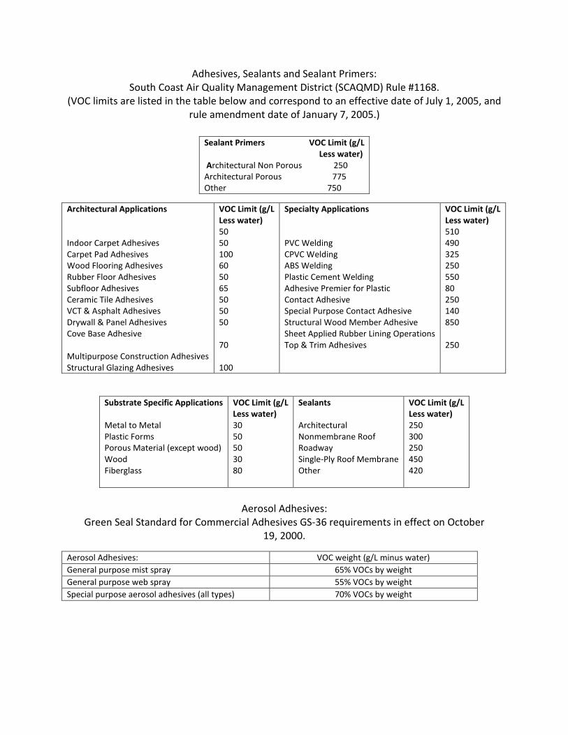
Adhesives, Sealants and Sealant Primers: South Coast Air Quality Management District (SCAQMD) Rule #1168.
(VOC limits are listed in the table below and correspond to an effective date of July 1, 2005, and rule amendment date of January 7, 2005.)
Architectural Applications Indoor Carpet Adhesives Carpet Pad Adhesives Wood Flooring Adhesives Rubber Floor Adhesives Subfloor Adhesives Ceramic Tile Adhesives VCT & Asphalt Adhesives Drywall & Panel Adhesives Cove Base Adhesive Multipurpose Construction Adhesives Structural Glazing Adhesives
VOC Limit (g/L Less water) 50 50 100 60 50 65 50 50 50 70 100
Specialty Applications PVC Welding CPVC Welding ABS Welding Plastic Cement Welding Adhesive Premier for Plastic Contact Adhesive Special Purpose Contact Adhesive Structural Wood Member Adhesive Sheet Applied Rubber Lining Operations Top & Trim Adhesives
VOC Limit (g/L Less water) 510 490 325 250 550 80 250 140 850 250
Substrate Specific Applications Metal to Metal Plastic Forms Porous Material (except wood) Wood Fiberglass
VOC Limit (g/L Less water) 30 50 50 30 80
Sealants Architectural Nonmembrane Roof Roadway Single-Ply Roof Membrane Other
VOC Limit (g/L Less water) 250 300 250 450 420
Aerosol Adhesives:
Green Seal Standard for Commercial Adhesives GS-36 requirements in effect on October 19, 2000.
Sealant Primers VOC Limit (g/L Less water) Architectural Non Porous 250 Architectural Porous 775 Other 750
Aerosol Adhesives: VOC weight (g/L minus water) General purpose mist spray 65% VOCs by weight General purpose web spray 55% VOCs by weight Special purpose aerosol adhesives (all types) 70% VOCs by weight

2.08 PAINTS AND COATINS (INTERIOR ONLY)
A. EQ 4.2: Field applied paints and coatings used on the interior of the building (defined as inside of the weatherproofing system and applied on-site) shall comply with the following criteria: Low-emitting paints and coatings are identified in Section 09900. The contractor is responsible for selecting materials/products that meet LEED requirements.
1. Architectural paints, coatings and primers applied to interior walls and
ceiling: Do not exceed the VOC content limits established in Green Seal Standard GS-11, Paints, First Edition, May 20, 1993.
a. Flats: 50 g/L
b. Non-Flats: 150 g/L
2. Anti-corrosive and anti-rust paints applied to interior ferrous metal
substrates: Do not exceed the VOC content limit of 250 g/L established in Green Seal Standard GC-03, Anti-Corrosive Paints, Second Edition, January 7, 1997.
3. Clear wood finished, floor coatings, stains, and shellacs, applied to
interior elements: Do not exceed the VOC content limits established in South Coast Air Quality Management District (SCAQMD) Rule 1113, Architectural Coatings, rules in effect on January 1, 2004.
a. Clear wood finishes: varnish 350 g/L; lacquer 550 g/L
b. Floor coatings: 100 g/L
c. Sealers: waterproofing sealers 250 g/L; sanding sealers 275 g/L; all
other sealers 200 g/L
d. Shellacs: Clear 730 g/L; pigmented 550 g/L
e. Stains: 250 g/L 2.09 CARPET AND CARPET CUSHION
A. EQ 4.3: All carpet installed in the building interior shall meet the testing and product requirements of the Carpet and Rug Institute’s Green Label Plus program.

B. All carpet cushion installed in the building interior shall meet the requirements of the Carpet and Rug Institute’s Green Label program.
C. All carpet adhesive shall meet the requirements of EQ Credit 4.1: VOC limit of 50
g/L 2.10 COMPOSITE WOOD PRODUCTS
A. Credit EQ 4.4: Composite wood and agrifiber products used on the interior of the building (defined as inside of the weatherproofing system) shall contain no added urea-formaldehyde resins. Laminating adhesives used to fabricate on-site and shop-applied composite wood and agrifiber assemblies shall contain no added urea-formaldehyde resins.
B. Composite wood and agrifiber products are defined as: particleboard, medium
density fiberboard (MDF), plywood, wheatboard, strawboard, panel substrates and door cores. Materials considered fit-out, furniture, and equipment (FF&E) are not considered base building elements and are not included.
PART 3 – EXECUTION
3.01 LEED COMPLIANCE, GENERAL
A. To achieve LEED certification, the project must meet all LEED prerequisites and
the credits designated in the “Y” column of Figure 1. The Contractor is responsible for compliance with the specific prerequisites and credits listed in this Section only. The Contractor is also responsible to provide documents for credits listed in the “?” column. These credits are optional but may be used if “Y” credits cannot be achieved.
B. Prior to start of work, determine that conditions of construction are acceptable to comply with LEED credit and prerequisite requirements. Do not proceed with work until unsatisfactory conditions have been corrected in a manner acceptable to Owner’s LEED advocate, Owner and Architect.
C. Correction of work that does not conform to specification requirements shall be performed at Contractor’s expense. Contractor shall provide the necessary documentation to show compliance of corrected work. Owner’s LEED advocate will be the sole judge in determining compliance with LEED credit requirements.

3.02 EROSION & SEDIMENTATION CONTROL
A. SS Prerequisite 1: Comply with sedimentation and erosion control plan, reference Civil drawings, and Division 2. The Plan is designed to meet the following objectives: 1. Prevent loss of soil during construction by stormwater run-off and/or
wind erosion, including protections of topsoil by stockpiling for reuse.
2. Prevent sedimentation of storm sewer or receiving streams and/or air pollution with dust and particulate matter.
3.03 IAQ MANAGEMENT DURING CONSTRUCTION
A. Credit EQ 3: Comply with Section (01354) – Construction Indoor Air Quality Management.
3.04 COMMISSIONING
A. EA Prerequisite 1 and Credit EA 3: Comply with the Commissioning Plan as designated by the Commissioning Authority.
3.05 CONSTRUCTION WASTE MANAGEMENT
A. Credit MR 2.1 and 2.2: Achieve a minimum of 75% diversion of construction waste from the landfill through recycling or salvage efforts.
(Insert Preliminary LEED Checklist)
Figure 1. Preliminary LEED Checklist
END OF SECTION

SECTION 01015
HANDICAPPED ACCESSIBILITY
PART 1 – HANDICAPPED ACCESSIBILITY 1.01 GENERAL A. The designer is reminded that Pacific Lutheran University is committed to making its facilities accessible and usable to the mobility impaired, the visually impaired, and the hearing impaired. As such, new facilities or those being modified, especially educational facilities, will be designed and constructed for access by all. B. Designs will comply with the Uniform Federal Access Standards (UFAS), and Americans with Disabilities Act of 1990 Accessibilities Guidelines (ADAAG). Caution shall be exercised such that all requirements are met for each of these regulations. Compliance for one DOES NOT necessarily ensure compliance with the aspects of all the applicable provisions. As such, details, dimensions, and construction specifications shall comply with all requirements set forth in ANSI A 117.1-1986, UFAS, and ADAAG publications for the following:
Space allowances and reach range Accessible route Walks-maximum slope shall not exceed 1 in 20 (5 percent gradient) Ramps-maximum slope shall not exceed 1 in 12 (8.3 percent gradient) Protruding objects Ground and floor surfaces Parking and passenger loading zones Curb ramps Ramps Stairs Elevators Platform lifts Doors Entrances Drinking fountains and water coolers Water closets Urinals Lavatories and mirrors Bathtubs Shower stalls Toilet Rooms

Bathrooms, bathing facilities and shower rooms Sinks Storage Handrails, grab bars, tub and shower seats Controls and operating mechanisms Alarms Tactile warnings Signage Telephones Seating tables and work surfaces Assembly areas Dwelling units
Note that the following are of special concern since they have, in some instances, been inadequately addressed in recent designs or are of highest priority for compliance and correction under current regulation:
Accessible route Entrances (50% accessible) Protruding objects Toilet rooms (all aspects) Drinking fountains and water coolers Ramps (slope and surface) Alarms (visual) Tactile warning Signage (tactile) Telephone
END OF SECTION

SECTION 01140
WORK RESTRICTIONS
PART 1 – GENERAL 1.01 USE OF PREMISES
A. Use of Site: Limit use of premises to work in areas indicated. Do not disturb portions of Site beyond areas in which the Work is indicated.
1. Limits: Confine construction operations to areas indicated by
Construction Documents. Confine storage of materials and support facilities to designated area adjacent to the building
2. Disposal of Waste Materials: Unless otherwise indicated, comply with
requirements in Division 1 Section “Execution Requirements” for disposal of waste material from the construction process.
a. Disposal of excess earth removed for excavation and inorganic
waste such as masonry and disposal of other organic waste material (such as wood and paper) from the construction process (on the site) will not be permitted.
1.02 SUSTAINABLE BUILDING REQUIREMENTS
See Section 01011 for sustainable building requirements affecting the work of this Section.
PART 2 – PRODUCT Not Used PART 3 – EXECUTION Not Used
END OF SECTION

SECTION 01230
ALTERNATES
PART 1 – GENERAL 1.01 SUBMISSTION REQUIREMENTS
A. Alternatives quoted on Bid Forms will be reviewed and accepted or rejected at the Owner’s option. Accepted alternative will be identified in the Owner-Contractor Agreement.
B. Alternates not incorporated into the Contract may be reinstated into the
Contract, at the Owner’s option, provided that the Owner so notifies the Contractor within thirty (30) calendar days after the notice to proceed.
C. Coordinate related work and modify surrounding work to integrate the Work of
each accepted alternate.
D. Coordination: Coordinate related work and modify or adjust adjacent work as necessary to ensure that work affected by each accepted alternate is complete and fully integrated into the project.
E. Alternate Proposals: Include all costs for labor, material, and equipment
necessary for a complete working system, assembly, or component as applicable to alternate specified, including costs to modify adjacent materials and/or assemblies affected by the alternate.
1. All costs for Performance Bond and Labor and Material Payment Bond
and Insurance shall be included in each Alternate Proposal.
2. Include as part of each alternate, miscellaneous devices, appurtenances, and similar items incidental to or required for a complete installation, whether or not mentioned as part of the alternate.
1.02 SUSTAINABLE BUILDING REQUIREMENTS
See Section 01011 for sustainable building requirements affecting the work of this Section.
PART 2 – PRODUCTS Not Used PART 3 – EXECUTION Not Used
END OF SECTION

SECTION 01250
CONTRACT MODIFICATION PROCEDURES
PART 1 – GENERAL 1.01 SUMMARY
A. This Section specifies administrative and procedural requirements for handling and processing Contract modifications.
1.02 MINOR CHANGES IN THE WORK
A. Architect will issue supplemental instruction authorizing Minor Changes in the Work, not involving adjustment to the Contract Sum or the Contract Time, on AIA Document G710, “Architect’s Supplemental Instructions.”
1.03 PROPOSAL REQUESTS
A. Owner-Initiated Proposal Requests: Architect will issue a detailed description of proposed changes in the Work that may require adjustment to the Contract Sum or the Contract Time. If necessary, the description will include supplemental or revised Drawings and Specifications.
1. Proposal Requests issued by Architect are for information only. Do not
consider them instruction either to stop work in progress or to execute the proposed change.
2. Within 10 days after receipt of Proposal Request, submit a quotation
estimating cost adjustments to the Contract Sum and the Contract Time necessary to execute the change.
a. Include a list of quantities of products required or eliminated and
unit costs, with total amount of purchases and credits to be made. If requested, furnish survey data to substantiate quantities.
b. Indicate applicable taxes, deliver charges, equipment rental, and amounts of trade discounts.
c. Include an updated Contractor’s Construction Schedule that indicates the effect of the change, including but not limited to, changes in activity duration, start and finish times, and activity

relationship. Use available total float before requesting an extension of the Contract Time.
B. Contractor-Initiated Proposals: If latent or unforeseen conditions require
modifications to the Contract, Contractor may propose changes by submitting a request for a change.
1. Include a statement outlining reasons for the change and the effect of
the change on the Work. Provide a complete description of the proposed change. Indicate the effect of the proposed change on the Contract Sum and the Contract Time.
2. Include a list of quantities of products required or eliminated and unit
costs, with total amount of purchases and credits to be made. If requested, furnish survey data to substantiate quantities.
3. Indicate applicable taxes, delivery charges, equipment rental, and
amounts of trade discounts.
4. Include an updated Contractor’s Construction Schedule that indicates the effect of the change, including, but not limited to, changes in activity duration, start and finish times, and activity relationship. Use available total float before requesting an extension of the Contract Time.
5. Comply with requirements in Division 1 Section “Product Requirements”
if the proposed change requires substitution of one product or system for product or system specified.
C. Proposal Request Form: Use AIA Document G709 for Proposal Request.
1.04 ALLOWANCES
A. Allowance Adjustment: To adjust allowance amounts, base each Change Order proposal on the difference between purchase amount and the allowance, multiplied by final measurement of work-in-place. If applicable, include reasonable allowances for cutting losses, tolerances, mixing wastes, normal product imperfections, and similar margins.
1. Include installation costs in purchase amount only where indicated as
part of the allowance.
2. If requested, prepare explanation and documentation to substantiate distribution of overhead costs and other margins claimed.

3. Submit substantiation of a change in scope of work, if any, claimed in Change Orders related to unit-cost allowances.
4. Owner reserves the right to establish the quantity of work-in-place by
independent quantity survey, measure, or count.
B. Submit claims for increased costs because of a change in scope or nature of the allowance described in the Contract Documents, whether for the Purchase Order amount or Contractor’s handling, labor, installation, overhead, and profit. Submit claims within 21 days of receipt of the Change Order or Construction Change Directive authorizing work to proceed. Owner will reject claims submitted later than 21 days after such authorization.
1.05 CHANGE ORDER PROCEDURES
A. On Owner’s approval of a Proposal Request, Contractor will issue a Change Order for signatures of Owner, Architect and Contractor on (AIA Document G701).
1.06 CONSTRUCTION CHANGE DIRECTIVE
A. Construction Change Directive: Architect may issue a Construction Change Directive on AIA Document G714. Construction Change Directive instructs Contractor to proceed with a change in the Work, for subsequent inclusion in a Change Order.
1. Construction Change Directive contains a complete description of change
in the Work. It also designates method to be followed to determine change in the Contract Sum of the Contract Time.
B. Documentation: Maintain detailed records on a time and material basis of work
required by the Construction Change Directive.
1. After completion of change, submit an itemized account and supporting data necessary to substantiate cost and time adjustments to the Contract.
1.07 SUSTAINABLE BUILDING REQUIREMENTS
See Section 01011 for sustainable building requirements affecting the work of this Section.

PART 2 – PRODUCTS Not Used PART 3 – EXECUTION Not Used
END OF SECTION

SECTION 01290
PAYMENT PROCEDURES
PART 1 – GENERAL 1.01 SUMMARY
A. This Section specifies administrative and procedural requirements necessary to prepare and process Applications for Payment.
1.02 SCHEDULE OF VALUES
A. Coordination: Coordinate preparation of the Schedule of Values with preparation of Contractor’s Construction Schedule.
1. Correlate line items in the Schedule of Values with other required
administrative forms and schedules, including the following:
a. Application for Payment forms with Continuation Sheets.
b. Submittals Schedule.
2. Submit the Schedule of Values to Owner at earliest possible date but no later than seven (7) days before the date scheduled for submittal of initial Applications for Payment.
B. Format and Content: Use the Project Manual table of contents as a guide to
establish line items for the Schedule of Values. Provide at least one line item for each Specification Section.
1. Identification: Include the following Project identification on the
Schedule of Values:
a. Project name and location.
b. Name of Architect.
c. Contractor’s name and address.
d. Date of submittal.

2. Arrange the Schedule of Values in tabular form with separate columns to indicate the following for each item listed:
a. Related Specification Section or Division.
b. Description of the Work.
c. Name of subcontractor.
d. Change Orders (numbers) that affect value.
e. Dollar value.
1) Percentage of the Contract Sum to nearest one-hundredth
percent, adjusted to total 100 percent.
3. Provide a breakdown of the Contract Sum in enough detail to facilitate continued evaluation of Applications for Payment and progress reports. Coordinate with the Project Manual table of contents. Provide several line items for principal subcontract amounts, where appropriate.
4. Round amounts to nearest whole dollar; total shall equal the Contract
Sum.
5. Provide a separate line item in the Schedule of Values for each part of the Work where Applications for Payment may include materials or equipment purchased or fabricated and stored, but not yet installed.
a. Differentiate between items stored on-site and items stored off-
site. Include evidence of insurance or bonded warehousing if required.
6. Provide separate line items in the Schedule of Values for initial cost of
materials, for each subsequent stage of completion, and for total installed value of that part of the Work.
7. Each item in the Schedule of Values and Applications for Payment shall be
complete. Include total cost and proportionate share of general overhead and profit for each item.
a. Temporary facilities and other major cost items that are not direct
cost of actual work-in-place may be shown either as separate line items in the Schedule of Values or distributed as general overhead expense, at Contractor’s option.

8. Schedule Updating: Update and resubmit the Schedule of Values before the next Applications for Payment when Change Orders or Construction Change Directives result in a change in the Contract Sum.
1.03 APPLICATIONS FOR PAYMENT
A. Each Application for Payment shall be consistent with previous applications and payments as certified by Architect and paid for by Owner.
1. Initial Application for Payment, Application for Payment at time of
Substantial Completion, and final Application for Payment involve addition requirements.
B. Payment Application Times: The date for each progress payment is indicated in
the Agreement between Owner and Contractor. The period of construction Work covered by each Application for Payment is the period indicated in the Agreement.
C. Payment Application Forms: Use AIA Document G702 and AIA Document G703
Continuation Sheets as form for Applications for Payment.
D. Application Preparation: Complete every entry on form. Notarize and execute by a person authorized to sign legal documents on behalf of Contractor. Architect will return incomplete applications without action.
1. Entries shall match data on the Schedule of Values and Contractor’s
Construction Schedule. Use updated schedules if revisions were made.
2. Include amount of Change Orders and Construction Change Directives issued before last day of construction period covered by Application.
E. Transmittal: Submit three (3) signed and notarized original copies of each
Application for Payment to Owner by a method ensuring receipt. One (1) copy shall include waivers of lien and similar attachments if required.
1. Transmit each copy with a transmittal form listing attachments and
recoding appropriate information about Application.
F. Waivers of Mechanic’s Lien: With each Application for Payment, submit waivers of mechanic’s liens from subcontractors, sub-subcontractors, and suppliers for construction period covered by the previous Application.
1. Submit partial waivers on each item for amount requested, before
deduction for retainage, on each item.

2. When an application show completion of an item, submit final for full waivers.
3. Owner reserves the right to designate which entities involved in the Work
must submit waivers.
4. Waiver Delays: Submit each Application for Payment with Contractor’s waiver of mechanic’s lien for construction period covered by the application.
a. Submit final Application for Payment with or preceded by final
waivers from every entity involved with performance of the Work covered by the application that is lawfully entitled to a lien.
5. Waiver Forms: Submit waivers of lien of forms, executed in a manner
acceptable to Owner.
G. Initial Application for Payment: Administrative actions and submittals that must precede or coincide with submittal of first Application for Payment include the following:
1. Schedule of Values.
2. Contractor’s Construction Schedule (preliminary if not final).
3. Submittals Schedule (preliminary if not final).
4. Certificates of insurance and insurance policies.
5. Performance and payment bonds.
6. Data needed to acquire Owner’s insurance.
H. Application for Payment at Substantial Completion: After issuing the Certificate
of Substantial Completion, submit an Application for Payment showing 100 percent completion for portion of the Work claimed as substantially complete.
1. Include documentation supporting claim that the Work is substantially
complete and a statement showing an accounting of changes to the Contract Sum.
2. This application shall reflect Certificates of Partial Substantial Completion issued previously for Owner occupancy of designated portions of the Work.

I. Final Payment Application: Submit final Application for Payment with releases and supporting documentation not previously submitted and accepted, including, but not limited to, the following:
1. Evidence of completion of the Project closeout requirements.
2. Insurance certificates for products and completed operations where
required and proof that taxes, fees, and similar obligations were paid.
3. Updated final statement, accounting for final changes to the Contract Sum.
4. AIA Document G706, “Contractor’s Affidavit of Payment of Debts and
Claims.”
5. AIA Document G706A, “Contractor’s Affidavit of Release of Liens.”
6. AIA Document G707, “Consent of Surety to Final Payment.” 1.04 SUSTAINABLE BUILDING REQUIREMENTS
See Section 01011 for sustainable building requirements affecting the work of this Section.
PART 2 – PRODUCTS Not Used PART 3 - EXECUTION Not Used
END OF SECTION

SECTION 01310
PROJECT MANAGEMENT AND COORDINATION
PART 1 – GENERAL 1.01 SUMMARY
A. This Section includes administrative provisions for coordinating construction operations on Project including, but not limited to, the following:
1. General project coordination procedures.
2. Conservation.
3. Coordination Drawings.
4. Administrative and supervisory personnel.
5. Project meetings.
B. Minutes: Contractor will record significant discussions and agreements
achieved. Prepare and distribute the meeting minutes to everyone concerned, including Owner and Architect.
1.02 COORDINATION
A. Coordination: Coordinate construction operations included in various Sections of the Specifications to ensure efficient and orderly installation of each part of the Work. Coordinate construction operations, included in different Sections, which depend on each other for proper installation, connection, and operation.
1. Schedule construction operations in sequence required to obtain the best
results where installation of one part of the Work depends on installation of other components, before or after its own installation.
2. Coordinate installation of different components with other contractors to
ensure maximum accessibility for required maintenance, service, and repair.
3. Make adequate provisions to accommodate items scheduled for later
installation.

B. If necessary, prepare memoranda for distribution to each party involved, outlining special procedures required for coordination. Include such items as required notices, reports, and list of attendees at meetings.
1. Prepare similar memoranda for Owner and separate contractors if
coordination of their Work is required.
C. Administrative Procedures: Coordinate scheduling and timing of required administrative procedures with other construction activities and activities of other contractors to avoid conflicts and to ensure orderly progress of the Work. Such administrative include, but are not limited to, the following:
1. Preparation of Contractor’s Construction Schedule.
2. Preparation of the Schedule of Values.
3. Installation and removal of temporary facilities and controls.
4. Delivery and processing of submittals.
5. Progress meetings
6. Pre-installation conferences.
7. Project closeout activities.
D. Conservation: Coordinate construction activities to ensure that operations are
carried out with consideration given to conservation of energy, water, and materials.
1. Salvage materials and equipment involved in performance of, but not
actually incorporated into, the Work. 1.03 SUBMITTALS
A. Coordination Drawings: Prepare Coordination Drawings if limited space availability necessitates maximum utilization of space for efficient installation of different components or if coordination is required for installation of products and materials fabricated by separate entities.
1. Indicate relationship of components shown on separate Shop Drawings.
2. Indicate required installation sequences.

3. Refer to Division 15 Section “Basic Mechanical Materials and Methods” and Division 16 Section “Basic Electrical Materials and Methods” for specific Coordination Drawing requirements for mechanical and electrical installations.
B. Staff Names: Within fifteen (15) days of starting construction operations, submit
a list of principal staff assignments, including superintendent and other personnel in attendance at Project site. Identify individuals and their duties and responsibilities; list addresses and telephone numbers of individuals assigned as standbys in the absence of individuals assigned to Project.
1. Post copies of list in Project meeting room, in temporary field office, and
by each temporary telephone. 1.04 EXTERIOR WALL MOCK-UP (ALTERNATE)
A. If required for project, provide freestanding 10’ X 10’ wall mock-up illustrating wall framing, water protection, CMU veneer, metal siding, flashings, downspout, sealant, storefront, glazing, etc. See attached drawings for evaluation of mock-up.
Mock-up will be constructed on-site and reviewed and approved prior to start of the construction of the building envelope. Mock-up will remain intact through substantial completion, at which time it will be removed by the general contractor.
1.05 ADMINISTRATIVE AND SUPERVISORY PERSONNEL
A. General: In addition to Project Superintendent, provide other administrative and supervisory personnel as required for proper performance of the Work.
1.06 PROJECT MEETINGS
A. General: Schedule and conduct meetings and conferences at Project site, unless otherwise indicated.
1. Attendees: Inform participants and others involved, and individuals
whose presence is required, of date and time of each meeting. Notify Owner and Architect of scheduled meeting dates and times.
2. Agenda: Prepare the meeting agenda. Distribute the agenda to all
invited attendees.

B. Preconstruction Conference: Schedule a preconstruction conference before starting construction, at a time convenient to Owner and Architect, but no later than fifteen (15) days after execution of the Agreement. Hold the conference at Project site or another convenient location. Conduct the meeting to review responsibilities and personnel assignments.
1. Attendees: Authorized representatives of Owner, Architect, and their
consultants; Contractor and its superintendent; major subcontractors; manufacturers; suppliers; and other concerned parties shall attend the conference. All participants at the conference shall be familiar with Project and authorized to conclude matters relating to the Work.
2. Agenda: Discuss items of significance that could affect progress,
including the following:
a. Tentative construction schedule.
b. Phasing.
c. Critical work sequencing.
d. Designation of responsible personnel.
e. Procedures for processing field decisions and Change Orders.
f. Procedures for processing Applications for Payment.
g. Distribution of the Contract Documents.
h. Submittal procedures.
i. Preparation of Record Documents.
j. Use of the premises.
k. Responsibility for temporary facilities and controls.
l. Parking availability.
m. Office, work, and storage areas.
n. Equipment deliveries and priorities.
o. First aid.

p. Security.
q. Progress cleaning.
r. Working hours.
s. LEED documentation and environmental procedures.
C. Pre-installation Conferences: Conduct a pre-installation conference at Project site before each construction activity that requires coordination with other construction.
1. Attendees: Installer and representatives of manufacturers and
fabricators involved in or affected by the installation and its coordination or integration with other materials and installations that have preceded or will follow, shall attend the meeting. Advise Architect of scheduled meeting dates.
2. Agenda: Review progress of other construction activities and
preparations for the particular activity under consideration, including requirements for the following:
a. Contract Documents.
b. Options.
c. Related Change Orders.
d. Purchases.
e. Deliveries.
f. Submittals.
g. Review of mock-ups.
h. Possible conflicts.
i. Compatibility problems.
j. Time schedules.
k. Weather limitations.

l. Manufacturer’s written recommendations.
m. Warranty requirements.
n. Compatibility of materials.
o. Acceptability of substrates.
p. Temporary facilities and controls.
q. Space and access limitations.
r. Regulations of authorities having jurisdiction.
s. Testing and inspecting requirements.
t. Required performance results.
u. Protection of construction and personnel.
v. LEED documentation and environmental procedures.
3. Record significant conference discussions, agreements, and disagreements.
4. Do not proceed with installation if the conference cannot be successfully
concluded. Initiate whatever actions are necessary to resolve impediments to performance of the Work and reconvene the conference at earliest feasible date.
D. Progress Meetings: Conduct progress meetings at weekly intervals. Coordinate
dates of meetings with preparation of payment requests.
1. Attendees: In addition to representatives of Owner and Architect, each contractor, subcontractor, supplier, and other entity concerned with current progress or involved in planning, coordination, or performance of future activities shall be represented at these meetings. All participants at the conference shall be familiar with Project and authorized to conclude matters relating to the Work.
2. Agenda: Review and correct or approve minutes of previous progress
meeting. Review other items of significance that could affect progress. Include topics for discussion as appropriate to status of Project.

a. Contractor’s Construction Schedule: Review progress since the last meeting. Determine whether each activity is on time, ahead of schedule, or behind schedule, in relation to Contractor’s Construction Schedule. Determine how construction behind schedule will be expedited; secure commitments from parties involved to do so. Discuss whether schedule revisions are required to ensure that current and subsequent activities will be completed within the Contract Time.
b. Review present and future needs of each entity present, including the following:
1) Interface requirements.
2) Sequence of operations.
3) Status of submittals.
4) Deliveries.
5) Off-site fabrication.
6) Access.
7) Site utilization.
8) Temporary facilities and controls.
9) Work hours.
10) Hazards and risks.
11) Progress cleaning.
12) Quality and work standards.
13) Change Orders.
14) Documentation of information for payment requests.
15) Waste management.
16) LEED documentation and environmental procedures.

3. Reporting: Distribute minutes of the meeting to each party present and to parties who should have been present. Include a brief summary, in narrative form, of progress since the previous meeting and report.
a. Schedule Updating: Revise Contractor’s Construction Schedule
after each progress meeting where revisions to the schedule have been made or recognized. Issue revised schedule concurrently with the report of each meeting.
E. Other Meetings at which Architect is not present: Provide meeting notes to
Architect upon request. 1.07 CONSTRUCTION WASTE MANAGEMENT MEETINGS
A. Either conduct separate construction waste management meetings or discuss waste management goals and issues as part of the following regular meetings:
1. Pre-construction meeting.
2. Pre-installation conference.
3. Regular job-site meetings.
4. Job safety meetings.
B. Pre-Construction Meeting: Include discussions on waste management
requirements per Section 01505 - Construction Waste Management in the pre-construction meeting.
C. Pre-Installation Conference: Include discussions on waste management goals
and requirements per Section 01505 – Construction Waste Management in all pre-fabrication meetings conducted with subcontractors or fabricators.
D. Progress Meetings: Include discussions on waste management requirements per
Section 01505 – Construction Waste Management in the regular job meetings conducted during the course of the Project.
E. Job Safety Meetings: Include discussions on waste management requirements
per Section 01505 – Construction Waste Management in the job safety meetings.

1.08 SUSTAINABLE BUILDING REQUIREMENTS
See Section 01011 for sustainable building requirements affecting the work of this Section.
PART 2 – PRODUCTS Not Used PART 3 – EXECUTION Not Used
END OF SECTION

SECTION 01320
CONSTRUCTION PROGRESS DOCUMENTATION
PART 1 – GENERAL 1.01 SUMMARY
A. This Section includes administrative and procedural requirements for documenting the progress of construction during performance of the Work, including the following:
1. Preliminary Construction Schedule.
2. Contractor’s Construction Schedule.
3. Submittals Schedule.
4. Special reports.
5. Construction photographs.
B. Related Sections include the following:
1. Division 1 Section “Payment Procedures” for submitting the Schedule of
Values.
2. Division 1 Section “Project Management and Coordination” for submitting and distributing meeting and conference minutes.
3. Division 1 Section “Submittal Procedures” for submitting schedules and
reports.
4. Division 1 Section “Quality Requirements” for submitting a schedule of tests and inspections.
5. Division 1 Section “Closeout Procedures” for submitting photographic
negatives as Project Record Documents and Project closeout. 1.02 SUBMITTALS
A. Qualification Data: For firms and persons specified in “Quality Assurance” Article to demonstrate their capabilities and experience. Include lists of completed

projects with project names and addresses, names and addresses of architects and owners, and other information specified.
B. Submittals Schedule: Submit three (3) copies of schedule. Arrange the following
information in a tabular format:
1. Scheduled date for first submittal.
2. Specification Section number and title.
3. Submittal category (action or informational).
4. Name of subcontractor.
5. Description of the Work covered.
6. Scheduled date for Architect’s final release or approval.
C. Preliminary Construction Schedule: Submit pdf format via e-mail.
D. Contractor’s Construction Schedule: Submit three (1) printed copies of initial schedule, on black-line print, large enough to show entire schedule for entire construction period and in pdf format via e-mail.
E. Construction Photographs: Submit digital files of each photographic view within
seven (7) days of taking photographs. Identify date photos were taken on images.
F. Special Reports: Submit two (2) copies at time of unusual event.
1.03 QUALITY ASSURANCE
A. Coordinate Qualifications: An individual of established reputation who has been regularly engaged as a professional photographer for not less than three (3) years.
1.04 COORDINATION
A. Coordinate preparation and processing of schedules and reports with performance of construction activities and with scheduling and reporting of separate contractors.

B. Coordinate Contractor’s Construction Schedule with the Schedule of Values, list of subcontracts, Submittals Schedule, progress reports, payment requests, and other required schedules and reports.
1. Secure time commitments for performing critical elements of the Work
from parties involved.
2. Coordinate each construction activity in the network with other activities and schedule them in proper sequence.
C. Auxiliary Services: Cooperate with photographer and provide auxiliary services
requested, including access to Project site and use of temporary facilities including temporary lighting.
1.05 SUSTAINABLE BUILDING REQUIREMENTS
See Section 01011 for sustainable building requirements affecting the work of this Section.
PART 2 – PRODUCTS 2.01 SUBMITTALS SCHEDULE
A. Preparation: Submit a schedule of submittals, arranged in chronological order by dates required by construction schedule. Include time required for review, re-submittal, ordering, manufacturing, fabrication, and delivery when establishing dates.
1. Coordinate Submittals Schedule with list of subcontracts, the Schedule of
Values, and Contractor’s Construction Schedule.
2. Initial Submittal: Submit concurrently with preliminary bar-chart schedule. Include submittals required during the first sixty (60) days of construction. List those required to maintain orderly progress of the Work and those required early because of long lead time for manufacture or fabrication.
a. At Contractor’s option, show submittals on the Preliminary
Construction Schedule, instead of tabulating them separately.
3. Final Submittal: Submit concurrently with the first complete submittal of Contractor’s Construction Schedule.

2.02 CONTRACTOR’S CONSTRUCTION SCHEDULE, GENERAL
A. Procedures: Comply with procedures contained in AGC’s “Construction Planning & Scheduling.”
B. Time Frame: Extend schedule from date established for the Notice of Award to
date of Final Completion.
1. Contract completion date shall not be changed by submission of a schedule that shows an early completion date, unless specifically authorized by Change Order.
C. Activities: Treat each story or separate area as a separate numbered activity for
each principal element of the Work. Comply with the following:
1. Activity Duration: Define activities so no activity is longer than twenty (20) days, unless specifically allowed by Architect.
2. Procurement Activities: Include procurement process activities for long
lead items and major items, requiring a cycle of more than sixty (60) days, as separate activities in schedule. Procurement cycle activities include, but are not limited to, submittals, approvals, purchasing, fabrication, and delivery.
a. Elevator, steel, and steel stairs, curtain wall and window systems.
3. Submittal Review Time: Include review and re-submittal times indicated
in Division 1 Section “Submittal Procedures” in schedule. Coordinate submittal review times in Contractor’s Construction Schedule with Submittals Schedule.
4. Commissioning: Include commissioning, punchlist, and closeout activities
on the Project Schedule.
5. Start-up and Testing Time: Include not less than sixty (60) days prior to substantial completion for start-up and testing.
6. Substantial Completion: Indicate completion in advance of date
established for Substantial Completion, and allow time for Architect’s administrative procedures necessary for certification of Substantial Completion.

D. Constraints: Include constraints and work restrictions indicated in the Contract Documents and as follows in schedule, and show how the sequence of the Work is affected.
1. Work under More Than One Contract: Include a separate activity for
each contract.
2. Products Ordered in Advance: Include a separate activity for each product. Include delivery date indicated in Division 1 Section “Summary.” Delivery dates indicated stipulate the earliest possible delivery date.
3. Work Restrictions: Show the effect of the following items on the
schedule:
a. Uninterruptible services.
b. Use of premises restrictions.
c. Seasonal variations.
d. Environmental control.
4. Work Stages: Indicate important stages of construction for each major portion of the Work, including, but not limited to, the following:
a. Subcontract awards.
b. Submittals.
c. Mock-ups.
d. Fabrication.
e. Sample testing.
f. Installation.
g. Tests and inspections.
h. Adjusting.
E. Milestones: Include milestones indicated in the Contract Documents in
schedule, including, but not limited to, the Notice to Proceed, Substantial Completion, and Final Completion.

F. Cost Correlation: At the head of schedule, provide a cost correlation line, indicating planned and actual costs. One the line, show dollar volume of the Work performed as of dates used for preparation of payment requests.
1. Refer to Division 1 Section “Payment Procedures” for cost reporting and
payment procedures.
G. Contract Modifications: For each proposed contract modification and concurrent with its submission, prepare a time-impact analysis using fragments to demonstrate the effect of the proposed change on the overall project schedule.
2.03 PRELIMINARY CONSTRUCTION SCHEDULE
A. Bar-Chart Schedule: Submit preliminary horizontal bar-chart-type construction schedule within seven (7) days of date established for the Notice to Proceed.
B. Preparation: Indicate each significant construction activity separately. Identify
first workday of each week with a continuous vertical line. Outline significant construction activities for first sixty (60) days of construction. Include skeleton diagram for the remainder of the Work and a cash requirement prediction based on indicated activities.
2.04 CONTRACTOR’S CONSTRUCTION SCHEDULE (CPM SCHEDULE)
A. General: prepare network diagrams using AON (activity-on-node) format.
B. CPM Schedule: Prepare Contractor’s Construction Schedule using a CPM network analysis diagram.
1. Develop network diagram in sufficient time to submit CPM schedule so it
can be accepted for use no later than thirty (30) days after date established for the Notice to Proceed.
2. Conduct educational workshops to train and inform key Project
personnel, including subcontractors’ personnel, in proper methods of providing data and using CPM schedule information.
3. Establish procedures for monitoring and updating CPM schedule and for
reporting progress. Coordinate procedures with progress meeting and payment request dates.
4. Use “one workday” as the unit of time.

C. CPM Schedule Preparation: Prepare a list of all activities required to complete the Work. Using the preliminary network diagram, prepare a skeleton network to identify probable critical paths.
1. Activities: Indicate the estimated time duration, sequence requirements,
and relationship of each activity in relation to other activities. Include estimated time frames for the following activities:
a. Preparation and processing of submittals.
b. Fabrication.
c. Installation.
2. Processing: Process data to product output data or a computer-drawn,
time-scaled network. Revise data, reorganize activity sequences, and reproduce as often as necessary to produce the CPM schedule within the limitations of the Contract Time.
3. Format: Mark the critical path. Locate the critical path near center of
network; locate paths with most float near the edges.
a. Sub-networks on separate sheets are permissible for activities clearly off the critical path.
D. Initial Issue of Schedule: Prepare initial network diagram from a list of straight
“early start-total float” sort. Identify critical activities. Prepare tabulated reports showing the following:
1. Contractor or subcontractor and the Work or activity.
2. Description of activity.
3. Principal events of activity.
4. Immediate preceding and succeeding activities.
5. Early and late start dates.
6. Activity duration in workdays.
7. Total float or slack time.
8. Average size of workforce.

9. Dollar value of activity (coordinated with the Schedule of Values).
E. Schedule Updating: Concurrent with making revisions to schedule, prepare tabulated reports showing the following:
1. Identification of activities that have changes.
2. Changes in early and late start dates.
3. Changes in early and late finish dates.
4. Changes in activity durations in workdays.
5. Changes in the critical path.
6. Changes in total float or slack time.
7. Changes in the Contract Time.
F. Value Summaries: Prepare two (2) cumulative value lists, sorted by finish dates.
1. In first list, tabulate activity number, early finish date, dollar value, and
cumulative dollar value.
2. In second list, tabulate activity number, late finish date, dollar value, and cumulative dollar value.
3. In subsequent issues of both lists, substitute actual finish dates for
activities completed as of list date.
4. Prepare list for ease of comparison with payment request; coordinate timing with progress meetings.
a. In both value summary lists, tabulate “actual percent complete”
and “cumulative value completed” with total at bottom.
b. Submit value summary printouts one (1) week before each regularly scheduled progress meeting.
2.05 SPECIAL REPORTS
A. General: Submit special reports directly to Owner within one (1) day of an occurrence. Distribute copies of report to parties affected by the occurrence.

B. Reporting Unusual Events: When an event of an unusual and significant nature occurs at Project site, whether or not related directly to the Work, prepare and submit a special report. List chain of events, persons participating, response by Contractor’s personnel, evaluation of results or effects, and similar pertinent information. Advise Owner in advance when these events are known or predictable.
PART 3 – EXECUTION 3.01 CONTRACTOR’S CONSTRUCTION SCHEDULE
A. Contractor’s Construction Schedule Updating: At monthly intervals, update schedule to reflect actual construction progress and activities. Issue schedule one (1) week before each regularly scheduled progress meeting.
1. Revise schedule immediately after each meeting or other activity where
revisions have been recognized or made. Issue updated schedule concurrently with the report of each such meeting.
2. Include a report with updated schedule that indicates every change,
including, but not limited to, changes in logic, durations, actual starts and finishes and activity durations.
3. As the Work progresses, indicate Actual Completion percentage for each
activity.
B. Distribution: Distribute copies of approved schedule to Architect/Owner, separate contractors, testing and inspecting agencies, and other parties identified by Contractor with a need-to-know schedule responsibility.
1. Post copies in Project meeting rooms and temporary field offices.
2. When revisions are made, distribute updated schedules to the same
parties and post in the same locations. Delete parties from distribution when they have completed their assigned portion of the Work and are no longer involved in performance of construction activities.
3.02 CONSTRUCTION PHOTOGRAPHS
A. Photographer: Engage a qualified commercial photographer to take construction photographs.
B. Provide digital files of photographic images.

C. Date Stamp: Unless otherwise indicated, date and time stamp each photograph as it is being taken so stamp is integral to photograph.
D. Periodic Construction Photographs: Take four (4) digital color photographs
monthly, coinciding with cutoff dates associated with each Application for Payment. Photographer shall select vantage points to best show status of construction and progress since last photographs were taken.
1. Field Office Prints: Retain one (1) set of prints of periodic photographs in
field office at Project site, available at all times for reference. Identify photographs the same as for those submitted to Architect.
END OF SECTION

SECTION 01330
SUBMITTAL PROCEDURES
PART 1 – GENERAL 1.01 SUMMARY
A. This Section includes administrative and procedural requirements for submitting Shop Drawings, Product Data, Samples, and other miscellaneous submittals.
B. Related Sections include the following:
1. Division 1 Section “Payment Procedures” for submitting Applications for
Payment.
2. Division 1 Section “Project Management and Coordination” for submitting Coordination Drawings.
3. Division 1 Section “Construction Progress Documentation” for submitting
schedules and reports, including Contractor’s Construction Schedule and the Submittals Schedule.
4. Division 1 Section “Quality Requirements” for submitting test and
inspection reports and Delegated-Design Submittals and for erecting mock-ups.
5. Division 1 Section “Closeout Procedures” for submitting warranties
operation and maintenance manuals.
6. Division 1 Section “Project Record Documents” for submitting Record Drawings, Record Specifications, and Records Product Data.
7. Division 1 Section “Operation and Maintenance Data” for operation and
maintenance manual requirements. 1.02 DEFINITIONS
A. Action Submittals: Written and graphic information that requires Architect’s responsive action.
B. Informational Submittals: Written information that does not require Architect’s
approval. Submittals may be rejected for not complying with requirements.

1.03 SUBMITTAL PROCEDURES
A. General: Electronic copies of CAD Drawings of the floor plans (only) will be provided by Architect for Contractor’s use in preparing submittals, contingent on provisions of Division 1, 00800, paragraph 3.12.11.
B. Coordination: Coordinate preparation and processing of submittals with
performance of construction activities.
1. Coordinate each submittal with fabrication, purchasing, testing, deliver, other submittals, and related activities that require sequential activity.
2. Coordinate transmittal of different types of submittals for related parts of
the Work so processing will not be delayed because of need to review submittals concurrently for coordination.
a. Architect reserves the right to withhold action on a submittal
requiring coordination with other submittals until related submittal are received.
C. Submittals Schedule: Comply with requirements in Division 1 Section
“Construction Progress Documentation” for list of submittals and time requirements for scheduled performance of related construction activities.
D. Processing Time: Allow enough time for submittal review, including time for re-
submittals, as follows. Time for review shall commence on Architect’s receipt of submittal.
1. Initial Review: Allow fifteen (15) days for initial review of each submittal.
Allow additional time if processing must be delayed to permit coordination with subsequent submittals. Architect will advise Contractor when a submittal being processed must be delayed for coordination.
2. Concurrent Review: Where concurrent review of submittals by
Architect’s consultants, Owner, or other parties is required, allow twenty-on (21) days for initial review of each submittal.
3. Direct Transmittal to Consultant: Where the Contract Documents
indicate that submittals may be transmitted directly to Architect’s consultants, provide duplicate copy of transmittal to Architect. Submittal will be returned to Architect before being returned to Contractor.

4. If intermediate submittal is necessary, process it in same manner as initial submittal.
5. Allow fifteen (15) days for processing each re-submittal.
6. No extension of the Contract Time will be authorized because of failure
to transmit submittals enough in advance of the Work to permit processing.
E. Identification: Place a permanent label or title block on each submittal for
identification.
1. Indicate name of firm or entity that prepared each submittal on label or title block.
2. Provide a space approximately 4 by 5 inches on label or beside title block
to record Contractor’s review and approval markings and action taken by Architect.
3. Include the following information on label for processing and recording
action taken:
a. Project name.
b. Date.
c. Name and address of Architect.
d. Name and address of Contractor.
e. Name and address of subcontractor.
f. Name and address of supplier.
g. Name of manufacturer.
h. Unique identifier, including revision number.
i. Number and title of appropriate Specification Section.
j. Drawing number and detail references, as appropriate.
k. Other necessary identification.

F. Deviations: Highlight, encircle, or otherwise identify deviations from the Contract Documents on submittals.
G. Additional Copies: Unless additional copies are required for final submittal, and
unless Architect observes non-compliance with provisions of the Contract Documents, initial submittal may serve as final submittal.
1. Submit one (1) copy of submittal to concurrent review in addition to
specified number of copies to Architect.
2. Additional copies submitted for maintenance manuals will not be marked with action taken and will be returned.
H. Transmittal: Package each submittal individually and appropriately for
transmittal and handling. Transmit each submittal using a transmittal form. Architect will return submittals, without review, received from sources other than Contractor.
1. On an attached separate sheet, prepared on Contractor’s letterhead,
record relevant information, requests for data, revisions other than those requested by Architect on previous submittals, and deviations from requirements of the Contract Documents, including minor variations and limitations. Include the same label information as the related submittal.
2. Include Contractor’s stamp, signed legibly, essentially as follows:
a. The undersigned, acting on behalf of the Contractor, certifies that
this submittal has been reviewed and is approved; products have been verified as being as specified, field measurements and field construction criteria have been or will be coordinated , and the submittal is in compliance with Contract Documents.
3. Transmittal Form: Provide locations on form for the following
information:
a. Project name.
b. Date.
c. Destination (To:)
d. Source (From:)
e. Names of subcontractor, manufacturer and supplier.

f. Category and type of submittal.
g. Submittal purpose and description.
h. Submittal and transmittal distribution record.
i. Remarks.
j. Signature of transmitter.
I. Distribution: Furnish copies of final submittals to manufacturers, subcontractors, suppliers, fabricators, installers, authorities having jurisdiction, and others as necessary for performance of construction activities. Show distribution on transmittal forms.
J. Use of Construction: Use only final submittals with mark indicating action taken
by Architect in connection with construction. 1.04 SUSTAINABLE BUILDING REQUIREMENTS
See Section 01011 for sustainable building requirements affecting the work of this Section.
PART 2 – PRODUCTS 2.01 ACTION SUBMITTALS
A. General: Prepare and submit Action Submittals required by individual Specification Sections.
1. Number of Copies: Submit three (3) copies of each submittal, unless
otherwise indicated. Architect will return two (2) copies. Mark up and retain one (1) returned copy as a Project Record Document.
a. Provide additional copies when review by additional parties are
required, as in Section 15050 and 16050.
B. Product Data: Collect information into a single submittal for each element of construction and type of product or equipment.
1. If information must be specially prepared for submittal because standard
printed data are not suitable for use, submit as Shop Drawings, not as Product Data.

2. Mark each copy of each submittal to show which products and options are applicable.
3. Include the following information, as applicable:
a. Manufacturer’s written recommendations.
b. Manufacturer’s product specifications.
c. Manufacturer’s installation instructions.
d. Standard color charts.
e. Manufacturer’s catalog cuts.
f. Wiring diagrams showing factory-installed wiring.
g. Printed performance curves.
h. Operational range diagrams.
i. Mill reports.
j. Standard product operating and maintenance manuals.
k. Compliance with recognized trade association standards.
l. Compliance with recognized testing agency standards.
m. Application of testing agency labels and seals.
n. Notation of coordination requirements.
C. Shop Drawings: Prepare Project-specific information, drawn accurately to scale.
Do not base Shop Drawings on reproductions of the Contract Documents or standard printed data.
1. Preparation: Include the following information, as applicable:
a. Dimensions.
b. Identification of products.
c. Fabrication and installation drawings.

d. Roughing-in and setting diagrams.
e. Wiring diagrams showing field-installed wiring, including power, signal, and control wiring.
f. Shopwork manufacturing instructions.
g. Templates and patterns.
h. Schedules.
i. Design calculations.
j. Compliance with specified standards.
k. Notation of coordination requirements.
l. Notation of dimensions established by field measurement.
2. Wiring Diagrams: Differentiate between manufacturer-installed and field-installed wiring.
3. Sheet Size: Except for templates, patterns, and similar full-size drawings,
submit Shop Drawings on sheets at least 8 – ½ by 11 inches (215 by 280 mm) but no larger than 30 by 40 inches (750 by 1000 mm).
4. Number of Copies: Submit three (3) black-line prints of each submittal,
unless prints are required for operation and maintenance manuals. Submit five (5) prints where prints are required for operation and maintenance manuals. Architect will retain two (2) prints; remainder will be returned. Mark up and retain one (1) returned print as a Project Record Drawing.
D. Coordination Drawings: Comply with requirements in Division 1 Section “Project
Management and Coordination.”
E. Samples: Prepare physical units of materials or products, including the following:
1. Comply with requirements Division 1 Section “Quality Requirement” for
mock-ups.

2. Samples for Initial Section: Submit manufacturer’s color charts consisting of units or sections of units showing the full range of colors, textures, and patterns available.
3. Samples for Verification: Submit full-size units or Samples of size
indicated, prepared from the same material to be used for the Work, cured and finished in manner specified, and physically identical with the product proposed for use, and that show full range of color and texture variations expected. Samples include, but are not limited to, the following: partial sections of manufactured or fabricated components; small cuts or containers of materials; complete units of repetitively used materials; swatches showing color, texture, a pattern; color range sets; and components used for independent testing and inspection.
4. Preparation: Mount, display, or package Samples in manner specified to facilitate review of qualities indicated. Prepare Samples to match Architect’s sample where so indicated. Attach label on unexposed side that includes the following:
a. Generic description of Sample.
b. Product name or name of manufacturer.
c. Sample source.
5. Additional Information: On an attached separate sheet, prepared on
Contractor’s letterhead, provide the following:
a. Size limitations.
b. Compliance with recognized standards.
c. Availability.
d. Delivery time.
6. Submit Samples for review of kind, color, pattern, and texture for a final check of these characteristics with other elements and for a comparison of these characteristics between final submittal and actual component as delivered and installed.
a. If variation in color, pattern, texture, or other characteristic in
inherent in the product represented by a Sample, submit at least

three (3) sets of paired units that show approximate limits of the variations.
b. Refer to individual Specification Sections for requirements for Samples that illustrate workmanship, fabrication techniques, details of assembly, connections, operation, and similar construction characteristics.
7. Number of Samples for Initial Selection: Submit one (1) full set of
available choices where color, pattern, texture, or similar characteristics are required to be selected from manufacturer’s product line. Architect will return submittal with options selected.
8. Number of Sample for Verification: Submit three (3) sets of Samples.
Architect will retain two (2) Sample sets; remainder will be returned. Mark up and retain one (1) returned Sample set as a Project Record Sample.
a. Submit a single Sample where assembly details, workmanship,
fabrication techniques, connections, operation, and other similar characteristics are to be demonstrated.
9. Disposition: Maintain sets of approved Samples at Project site, available
for quality-control comparisons throughout the course of construction activity. Sample sets may be used to determine final acceptance of construction associated with each set.
a. Samples that may be incorporated into the Work are indicated in
individual Specification Sections. Such Samples must be in an undamaged condition at time of use.
b. Samples not incorporated into the Work, or otherwise designated as Owner’s property, are the property of Contractor.
F. Product Schedule of List: Prepare a written summary indicating types of
products required for the Work and their intended location. Include the following information in tabular form:
1. Type of product. Include unique identifier for each product.
2. Number and name of room or space.
3. Location within room or space.

G. Delegated-Design Submittal: Comply with requirements in Division 1 Section “Quality Requirements.”
H. Submittals Schedule: Comply with requirements in Division 1 Section
“Construction Progress Documentation.”
I. Application for Payment: Comply with requirements in Division 1 Section “Payment Procedures.”
J. Schedule of Values: Comply with requirements in Division 1 Section “Payment
Procedures.”
K. Subcontract List: Prepare a written summary identifying individuals or firms proposed for each portion of the Work, including those who are to furnish products or equipment fabricated to a special design. Include the following information in tabular form:
1. Name, address, and telephone number of entity performing subcontract
or supplying products.
2. Number and title of related Specification Section(s) covered by subcontract.
3. Drawing number and detail references, as appropriate, covered by
subcontract.
L. Maintenance Schedules: Prepare a written summary identifying maintenance schedules or procedures for each portion of the Work, including surface finishes, products or equipment fabricated to a special design.
2.02 INFORMATIONAL SUBMITTALS
A. General: Prepare and submit informational Submittals required by other Specification Sections.
1. Number of Copies: Submit two (2) copies of each submittal, unless
otherwise indicated. Architect will not return copies.
2. Certificates and Certifications: Provide a notarized statement that includes signature of entity responsible for preparing certification. Certificates and certifications shall be signed by an officer or other individual authorized to sign documents on behalf of that entity.

3. Test and Inspection Reports: Comply with requirements in Division 1 Section “Quality Requirements.”
4. LEED Compliance Submittals: Comply with Section 01101.
B. Contractor’s Construction Schedule: Comply with requirements in Division 1
Section “Construction Progress Documentation.”
C. Qualification Data: Prepare written information that demonstrates capabilities and experience of firm or person. Include lists of completed projects with project names and addresses, names and addresses of architects and owners, and other information specified.
D. Product Certificates: Prepare written statements on manufacturer’s letterhead
certifying that product complies with requirements.
E. Welding Certificates: Prepare written certification that welding procedures and personnel comply with requirements. Submit record of Welding Procedure Specification (WPS) and Procedure Qualification Record (PQR) on AWS forms. Include names of firms and personnel certified.
F. Installer Certificates: Prepare written statements on manufacturer’s letterhead
certifying that Installer complies with requirements and, where required, is authorized for this specific Project.
G. Manufacturer Certificates: Prepare written statements on manufacturer’s
letterhead certifying that manufacturer complies with requirements. Include evidence of manufacturing experience where required.
H. Material Certificates: Prepare written statements on manufacturer’s letterhead
certifying that material complies with requirements.
I. Material Test Reports: Prepare reports written by a qualified testing agency, on testing agency’s standard form, indicating and interpreting test results of material for compliance with requirements.
J. Preconstruction Test Reports: Prepare reports written by a qualified testing
agency, on testing agency’s standard form, indicating and interpreting results of tests performed before installation of product, for compliance with performance requirements.
K. Compatibility Test Reports: Prepare reports written by a qualified testing
agency, on testing agency’s standard form, indicating and interpreting results of

compatibility tests performed before installation of product. Include written recommendations for primers and substrate preparation needed for adhesion.
L. Field Test Reports: Prepare reports written by a qualified testing agency, on
testing agency’s standard form, indicating and interpreting results of field tests performed either during installation of product or after product is installed in its final location, for compliance with requirements.
M. Product Test Reports: Prepare written reports indicating current product
produced by manufacturer complies with requirements. Base reports on evaluation of tests performed by manufacturer and witnessed by a qualified testing agency, or on comprehensive tests performed by a qualified testing agency.
N. Research/Evaluation Reports: Prepare written evidence, from a model code
organization acceptable to authorities having jurisdiction, that product complies with building code in effect for Project. Include the following information:
1. Name of evaluation organization.
2. Date of evaluation.
3. Time period when report is in effect.
4. Product and manufacturer’s names.
5. Description of product.
6. Test procedures and results.
7. Limitations of use.
O. Maintenance Data: Prepare written and graphic instructions and procedures for
operation and normal maintenance of products and equipment. Comply with requirements in Division 1 Section “Operation and Maintenance Data.”
P. Design Data: Prepare written and graphic information, including but not limited
to, performance and design criteria, list of applicable codes and regulations, and calculations. Include list of assumptions and other performance and design criteria and a summary of loads. Include load diagrams if applicable. Provide name and version of software, if any, used for calculations. Include page numbers.

Q. Manufacturer’s Instructions: Prepare written or published information that documents manufacturer’s recommendations, guidelines, and procedures for installing or operating a product or equipment. Include name of product and name, address, and telephone number of manufacturer. Include the following as applicable:
1. Preparations of substrates.
2. Required substrate tolerances.
3. Sequence of installation or erection.
4. Required installation tolerances.
5. Required adjustments.
6. Recommendations for cleaning and protection.
R. Manufacturer’s Field Reports: Prepare written information documenting
factory-authorized service representative’s tests and inspections. Include the following, as applicable:
1. Name, address, and telephone number of factory-authorized service
representative making report.
2. Statement on condition of substrates and their acceptability for installation of product.
3. Statement that products at Project site comply with requirements.
4. Summary of installation procedures being followed, whether they comply
with requirements and, if not, what corrective action was taken.
5. Results of operational and other tests and a statement of whether observed performance complies with requirements.
6. Statement whether conditions, products, and installation will affect
warranty.
7. Other required items indicated in individual Specification Sections.
S. Insurance Certificates and Bonds: Prepare written information indicating current status of insurance or bonding coverage. Include name of entity covered by

insurance or bond, limits of coverage, amounts of deductibles, if any, and term of the coverage.
T. Construction Photographs: Comply with requirements in Division 1 Section
“Construction Progress Documentation.”
U. Material Safety Data Sheets: Submit information directly to Owner. If submitted to Architect, Architect will not review this information but will return it with no action taken.
PART 3 – EXECUTION 3.01 CONTRACTOR’S REVIEW
A. Review each submittal and check for compliance with the Contract Documents. Note corrections and field dimensions. Mark with approval stamp before submitting to Architect.
B. Approval Stamp: Stamp each submittal with a uniform, approval stamp. Include
Project name and location, submittal number, Specification Section title and number, name of reviewer, date of Contractor’s approval, and statement certifying that submittal has been reviewed, checked, and approved for compliance with the Contract Documents.
3.02 ARCHITECT’S ACTION
A. General: Architect will not review submittals that do not bear Contractor’s approval stamp and will return them without action.
B. Action Submittals: Architect will review each submittal, make marks to indicate
corrections or modifications required, and return it. Architect will stamp each submittal with an action stamp and will mark stamp appropriately to indicate action taken, as follows:
1. Review of submittals is only for general conformance with the design
concept of the Project and general compliance with the information given in the Contract Documents. The review does not affect the Contractor’s responsibility to perform all Contract requirements with no change in Contract price or time. Any actions shown by the Architect are subject to the requirements of the plans, specifications and other Contract Documents. The Contractor is responsible to confirm and correlate dimensions at the site for information that pertains to the fabrication processes, for the means, methods, techniques, procedures, sequences

and quantities necessary to complete the Contract and for coordination of the work of all trades and satisfactory performance of its work. The review by the Architect is undertaken solely to satisfy Architect’s obligations, if any, to the Owner and shall not give rise to any claim by the Contractor or other parties against the Architect or Owner.
C. Informational Submittals: Architect will review each submittal and will not
return it, or will reject and return it if it does not comply with requirements. Architect will forward each submittal to appropriate party.
D. Submittals not required by the Contract Documents will not be reviewed and
may be discarded.
END OF SECTION

SECTION 01354
CONSTRUCTION INDOOR AIR QUALITY MANAGEMENT
PART 1 – GENERAL 1.01 SUMMARY
A. Section includes:
1. Description of the Construction Indoor Air Quality (IAQ) Management Plan
2. IAQ Construction Requirements
B. Construction Indoor Air quality Requirements:
1. The Owner has set indoor air quality goals for job site operations on
project, within the limits of the construction schedule, contract sum, and available materials, equipment, products and services. These goals include:
a. Protect workers on the site from undue health risks during
construction.
b. Install low-VOC materials as specified in Part 2 – Product.
c. Prevent residual problems with indoor air quality in the completed building.
C. Drawings, the provisions of the Agreement, the General Conditions, and Division
1 specification sections apply to work of this Section.
D. Substitutions: Substitutions will be considered only under the terms and conditions of Section 006325.
1.02 REFERENCES
A. Sheet Metal and Air Conditioning National Contractors Association (SMACNA) IAQ Guideline for Occupied Buildings Under Construction, 1995.
B. “Construction IAQ Management: Job-site Strategies for Ensuring a Healthy
Building,” Environmental Building News, Vol. 11, No. 5, May 2002. Good

discussion of strategies for controlling airborne pollutants and moisture during construction. Provides checklist based on SMACNA guideline referenced above.
C. Construction IAQ Management Plan as per LEED NC v2.2 Reference Guide.
D. Indoor Chemical & Pollutant Source Control as per LEED NC v2.2 Reference
Guide. 1.03 SUBMITTALS
A. Submit the following in accordance with Section 013300 – Submittal Procedures.
B. Within fourteen (14) days after receipt of Notice of Award and prior to beginning any work on the site, the Contractor shall develop and submit to the Owner for review a construction indoor air quality management plan.
C. The IAQ management plan shall comply with the five (5) requirements of
SMACNA IAQ Guideline for Occupied Buildings under Construction, 1995, Chapter 3: HVAC protection, source control, pathway interruption, housekeeping, and scheduling and shall include:
1. List of IAQ protective measures to be instituted on the site:
a. HVAC system protection during construction.
b. Source control through specification and installation of low-toxic
or non-toxic materials.
c. Pathway interruption to isolate work areas where emitting materials are being installed.
d. Housekeeping to protect materials that are stored before installation and to avoid spreading contamination through the Project.
e. Sequencing installation of materials to avoid contaminating absorptive materials during construction.
2. Schedule for inspection and maintenance of IAQ measures.
E. LEED Documentation: Provide documentation indicating that the requirements
of LEED-NC Credit EQ 3 have been met.
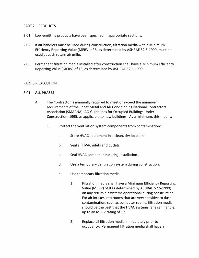
PART 2 – PRODUCTS 2.01 Low-emitting products have been specified in appropriate sections. 2.02 If air handlers must be used during construction, filtration media with a Minimum
Efficiency Reporting Value (MERV) of 8, as determined by ASHRAE 52.5-1999, must be used at each return air grille.
2.03 Permanent filtration media installed after construction shall have a Minimum Efficiency
Reporting Value (MERV) of 13, as determined by ASHRAE 52.5-1999. PART 3 – EXECUTION 3.01 ALL PHASES
A. The Contractor is minimally required to meet or exceed the minimum requirements of the Sheet Metal and Air Conditioning National Contractors Association (SMACNA) IAQ Guidelines for Occupied Buildings Under Construction, 1995, as applicable to new buildings. As a minimum, this means:
1. Protect the ventilation system components from contamination:
a. Store HVAC equipment in a clean, dry location.
b. Seal all HVAC inlets and outlets.
c. Seal HVAC components during installation.
d. Use a temporary ventilation system during construction.
e. Use temporary filtration media.
1) Filtration media shall have a Minimum Efficiency Reporting
Value (MERV) of 8 as determined by ASHRAE 52.5-1999) on any return air systems operational during construction. For air intakes into rooms that are very sensitive to dust contamination, such as computer rooms, filtration media should be the best that the HVAC systems fans can handle, up to an MERV rating of 17.
2) Replace all filtration media immediately prior to
occupancy. Permanent filtration media shall have a

Minimum Efficiency Reporting Value (MERV) of 13, as determined by ASHRAE 52.5-1999.
f. Clean air plenums before closing them in.
g. Inspect filters regularly.
2. Provide pollution source control:
a. Protect on-site stored and installed absorptive materials (such as
insulation, drywall, and wood) from moisture damage and from contamination by construction duet, debris, and fumes during all phases of construction, both before and after installation.
b. Do not install moisture-damaged materials.
c. Ensure that construction detailing will not result in moisture intrusion.
d. Use low-emitting products (specified in appropriate sections).
e. Provide strategies to avoid tracking pollutants into the work areas.
f. Allow high-VOC materials to off-gas prior to installation. For example, all dry furnishing and materials (such as carpet, floor tile, acoustical tile, textiles, office furniture, wood shelving, etc.) shall be allowed to “air-out” in clean environments prior to installation in a building.
g. Use the least amount of “wet” materials (such as adhesives, sealants, glazes, caulks, paints, etc.) during construction and product applications while still maintaining installation protocol required to meeting for manufacturer’s warrantee requirements.
3. Provide interruption of pollutant pathways:
a. Use an air barrier or pressure differential to isolate areas at
different stages of completion.
4. Practice healthy housekeeping.
a. Minimize accumulation of dust and other contaminants.

b. Confine dust-generating activities.
c. Suppress dust.
1) Use wet sanding for gypsum board assemblies. Exception: Dry sanding allowed subject to Owner approval of the following measures:
a) Full isolation of space under finishing
b) Plastic protection sheeting is installed to provide
air sealing during the sanding
c) Closure of all air system devices and ductwork
d) Sequencing of construction precludes the possibility of contamination of other spaces with gypsum dust
e) Worker protection is provided
d. Clean up dust.
e. Clean up spills.
f. Keep work area dry.
g. Seal containers of volatile liquids.
5. Schedule construction activities to reduce exposure to VOCs.
a. Install porous materials only after closing in the building.
b. Account for curing time and off-gassing when scheduling
construction activities.
c. Allow wet-spray cellulose to dry before covering.
d. Install carpeting, acoustical panels, and furnishings after interior finishes have been allowed time to cure/dry in accordance with other good building practices.
e. Provide adequate ventilation during curing period.

1) Provide supplemental (spot) ventilation for at least 72 hours after work is completed. Preferred HVAC system operation uses supply air fans and ducts only; exhaust provided through windows. Use exhaust fans to pull exhaust air from deep interior locations. Stair towers and other paths to exterior can be useful during this process.
B. Use safety meetings, signage, and subcontractor agreements to communicate
the goals of the construction indoor air quality management construction plan.
C. Conduct regular inspection and maintenance of indoor air quality measures including ventilation system protection, and ventilation rate.
D. Require VOC-safe masks for interior and exterior workers installing VOC-emitting
products (products that contain 150 g/L or more VOCs).
E. Use low-toxic cleaning supplies for surfaces, equipment, and worker’s personal use. Options include several soybean-based solvents and cleaning options and citrus-based cleaners. (SoySolv provides several soy-based solvents and cleaning options. Phone 1-800-231-4274 or www.soysolv.com.)
F. Smoking is prohibited on the construction site.
G. Perform “Building Flush-Out” in accordance with the requirements of LEED EQ
3.2.
END OF SECTION

SECTION 01400
QUALITY REQUIREMENTS
PART 1 – GENERAL 1.01 SUMMARY
A. This Section includes administrative and procedural requirements for quality assurance and quality control.
B. Testing and inspecting services are required to verify compliance with
requirements specified or indicated. These services do not relieve Contractor of responsibility for compliance with the Contract Document requirements.
1. Specific quality-control requirements for individual construction activities
are specified in the Sections that specify those activities. Requirements in those Sections may also cover production of standard products.
2. Specified test, inspections, and related actions do not limit Contractor’s
quality-control procedures that facilitate compliance with the Contract Document requirements.
3. Requirements for Contractor to provide quality-control services required
by Architect, Owner, or authorities having jurisdiction are not limited by provisions of this Section.
C. Related Sections include the following:
1. Division 1 Section “Allowances” for testing and inspecting allowances.
2. Division 1 Section “Cutting and Patching” for repair and restoration of
construction distributed by testing and inspecting activities.
3. Divisions 2 through 16 Section for specific test and inspection requirements.
1.02 DEFINITIONS
A. Quality-Assurance Services: Activities, actions, and procedures performed before and during execution of the Work to guard against defects and deficiencies and ensure that proposed construction complies with requirements.
B. Quality-Control Services: Tests, inspections, procedures, and related actions during and after execution of the Work to evaluate that completed construction complies with requirements. Services do not include contract enforcement activities performed by Architect.
C. Mock-ups: Full-size, physical example assemblies to illustrate finishes and
materials. Mock-ups are used to verify selections made under Sample submittals, to demonstrate aesthetic effects and, where indicated, qualities of materials and execution, and to review construction, coordination, testing, or operation; they are not Samples. Mock-ups establish the standard by which the Work will be judged.
D. Testing Agency: An entity engaged to perform specific tests, inspections, or
both. Testing laboratory shall mean the same as testing agency. 1.03 DELEGATED DESIGN
A. Performance and Design Criteria: Where professional design services or certifications by a design professional are specifically required of Contractor by the Contract Documents, provide products and systems complying with specific performance and design criteria indicated.
1. If criteria indicated are not sufficient to perform services or certifications
required, submit a written request for additional information to Architect.
1.04 SUBMITTALS
A. Delegated-Design Submittal: In addition to Shop Drawings, Product Data, and other required submittals, submit a statement, signed and sealed by the responsible design professional, for each product and system specifically assigned to Contractor to be designed or certified by a design professional, indicating that the products and systems are in compliance with performance and design criteria indicated. Include list of codes, loads, and other factors used in performing these services.
B. Reports: Prepare and submit certified written reports that include the following:
1. Date of issue.
2. Project title and number.
3. Name, address, and telephone number of testing agency.

4. Dates and locations of samples and tests or inspections.
5. Names of individuals making tests and inspections.
6. Description of the Work and test and inspection method.
7. Identification of product and Specification Section.
8. Complete test or inspection data.
9. Test and inspection results and an interpretation of test results.
10. Ambient conditions at time of sample taking and testing and inspecting.
11. Comments or professional opinion on whether tested or inspected Work complies with the Contract Document requirements.
12. Name and signature of laboratory inspector.
13. Recommendations on retesting and re-inspecting.
1.05 QUALITY ASSURANCE
A. Fabricator Qualifications: A firm experienced in producing products similar to those indicated for this Project and with a record of successful in-service performance, as well as sufficient production capacity to produce required units.
B. Factory-Authorized Service Representative Qualifications: An authorized
representative of manufacturer who is trained and approved by manufacturer to inspect installation of manufacturer’s products that are similar in material, design, and extent to those indicated for this Project.
C. Installer Qualifications: A firm or individual experienced in installing, erecting, or
assembling work similar in material, design, and extent to that indicated for this Project, whose work has resulted in construction with a record of successful in-service performance.
D. Manufacturer Qualifications: A firm experienced in manufacturing products or
systems similar to those indicated for this Project and with a record of successful in-service performance.
E. Professional Engineer Qualifications: A professional engineer is who is legally
qualified to practice in jurisdiction where Project is located and who is experienced in providing engineering services of the kind indicated. Engineering

services are defined as those performed for installations of the system, assembly, or products that are similar to those indicated for this Project in material, design, and extent.
F. Specialists: Certain sections of the Specifications require that specific
construction activities shall be performed by entities who are recognized experts in those operations. Specialists shall satisfy qualification requirements indicated and shall be engaged for the activities indicated.
1. Requirement for specialists shall not supersede building codes and similar
regulations governing the Work, nor interfere with local trade-union jurisdictional settlements and similar conventions.
G. Testing Agency Qualifications: An agency with the experience and capability to
conduct testing and inspecting indicated, as documented by ASTM E 548, and that specializes in types of tests and inspections to be performed.
H. Preconstruction Testing: Testing agency shall perform preconstruction testing
for compliance with specified requirements for performance and test methods.
1. Contractor responsibilities include the following:
a. Provide test specimens and assemblies representative of proposed materials and construction. Provide sizes and configurations of assemblies to adequately demonstrate capability of product to comply with performance requirements.
b. Submit specimens in a timely manner with sufficient time for testing and analyzing results to prevent delaying the Work.
c. Fabricate and install test assemblies using installer who will perform the same tasks for Project.
d. When testing is complete, remove assemblies; do not reuse materials on Project.
2. Testing Agency Responsibilities: Submit a certified written report of each
test, inspection, and similar quality-assurance service to Architect, with copy to Contractor. Interpret tests and inspections and state in each report whether tested and inspected work complies with or deviates from the Contract Documents.

I. Mock-ups: Before installing portions of the Work requiring mockups, build mockups for each form of construction and finish required to comply with the following requirements, using materials indicated for the completed Work:
1. Build mockups in location and of size indicated or, if not indicated as
directed by Architect.
2. Notify Architect & Owner seven (7) days in advance of dates and times when mockups will be constructed.
3. Demonstrate the proposed range of aesthetic effects and workmanship.
4. Obtain Architect’s approval of mockups before stating work, fabrication,
or construction.
5. Maintain mockups during construction in an undisturbed as a standard for judging the completed Work.
1.06 QUALITY CONTROL
A. Owner Responsibilities: Where quality-control services are indicated as Owner’s responsibility, Owner will engage a qualified testing agency to perform these services.
1. Owner will furnish Contractor with names, addresses, and telephone
numbers of testing agencies engaged and a description of the types of testing and inspecting they are engaged to perform.
2. Costs for retesting and re-inspecting construction that replaces or is
necessitated by work that failed to comply with the Contract Documents will be charged to Contractor.
B. Contractor Responsibilities: Unless otherwise indicated, provide quality-control
services specified and required by authorities having jurisdiction.
1. Where services are indicated as Contractor’s responsibility, engage a qualified testing agency to perform these quality-control services.
a. Contractor shall not employ the same entity engaged by Owner,
unless agreed to in writing by Owner.
2. Notify testing agencies at least 24 hours in advance of time when Work that requires testing or inspecting will be performed.

3. Where quality-control services are indicated as Contractor’s responsibility, submit a certified written report, in duplicate, or each quality-control service.
4. Testing and inspecting requested by Contractor and not required by the
Contract Documents are Contractor’s responsibility.
5. Submit additional copies of each written report directly to authorities having jurisdiction, when they so direct.
C. Special Tests and Inspections: Owner will engage a testing agency to conduct
special tests and inspections required by authorities having jurisdiction as the responsibility of Owner.
1. Testing agency will notify Architect and Contractor promptly of
irregularities and deficiencies observed in the Work during performance of its services.
2. Testing agency will submit a certified written report of each test,
inspection, and similar quality-control service to Architect & or Owner with copy to Contractor and to authorities having jurisdiction.
3. Testing agency will submit a final report of special tests and inspections
at Substantial Completion, which includes a list of unresolved deficiencies.
4. Testing agency will interpret tests and inspections and state in each
report whether tested and inspected work complies with or deviates from the Contract Documents.
5. Testing agency will retest and re-inspect corrected work.
D. Manufacturer’s Field Services: Where indicated, engage a factory-authorized
service representative to inspect field-assembled components and equipment installation, including service connections. Report results in writing.
E. Retesting/Re-Inspecting: Regardless of whether original tests or inspections
were Contractor’s responsibility, provide quality-control services, including retesting and re-inspecting, for construction that revised or replaced Work that failed to comply with requirements established by the Contract Documents.
F. Testing Agency Responsibilities: Cooperate with Architect and Contractor in
performance of duties. Provide qualified personnel to perform required tests and inspections.

1. Notify Architect and Contractor promptly of irregularities or deficiencies observed in the Work during performance of its services.
2. Interpret tests and inspections and state in each report whether tested
and inspected work complies with or deviates from requirements.
3. Submit a certified written report, in duplicate, of each test, inspection, and similar quality-control service through Contractor.
4. Do not release, revoke, alter, or increase requirements of the Contract
Documents or approve or accept any portion of the Work.
5. Do not perform any duties of Contractor.
G. Associated Services: Cooperate with agencies performing required tests, inspections, and similar quality-control services, and provide reasonable auxiliary services as requested. Notify agency sufficiently in advance of operations to permit assignment of personnel. Provide the following:
1. Access to the Work.
2. Incidental labor and facilities necessary to facilitate tests and inspections.
3. Adequate quantities of representative sample of materials that require
testing and inspecting. Assist agency in obtaining samples.
4. Facilities for storage and filed-curing of test samples.
5. Delivery of samples to testing agencies.
6. Preliminary design mix proposed for use for material mixes that require control by testing agency.
7. Security and protection for samples and for testing and inspecting
equipment at Project site.
H. Coordination: Coordinate sequence of activities to accommodate required quality-assurance and quality-control services with a minimum of delay and to avoid necessity of removing and replacing construction to accommodate testing and inspecting.
1. Schedule times for tests, inspections, obtaining samples, and similar
activities.

1.07 SUSTAINABLE BUILDING REQUIREMENTS
See Section 01011 for sustainable building requirements affecting the work of this Section.
PART 2 – PRODUCTS Not Used PART 3 – EXECUTION 3.01 REPAIR AND PROTECTION
A. General: On completion of testing, inspecting, sample taking and similar services, repair damaged construction and restore substrates and finishes.
1. Provide materials and comply with installation requirements specified in
other Sections of these Specifications. Restore patched areas and extend restoration into adjoining areas in a manner that eliminates evidence of patching.
2. Comply with the Contract Document requirements for Division 1 Section
“Cutting and Patching.”
B. Protect construction exposed by or for quality-control service activities.
C. Repair and protection are Contractor’s responsibility, regardless of the assignment of responsibility for quality-control services.
END OF SECTION

SECTION 01420
REFERENCES
PART 1 – GENERAL 1.01 DEFINITIONS
A. General: Basic Contract definitions are included in the Conditions of the Contract.
B. “Approved”: When used to convey Architect’s action on Contractor’s submittals,
applications, and requests, “approved” is limited to Architect’s duties and responsibilities as stated in the Conditions of the Contract.
C. “Directed”: A command or instruction by Architect. Other terms including
“requested,” “authorized,” “selected,” “approved,” “required,” and “permitted” have the same meaning as “directed.”
D. “Indicated”: Requirements expressed by graphic representations or in written
form on Drawings, in Specifications, and in other Contract Documents. Other terms including “shown,” “noted,” “scheduled,” and “specified” have the same meaning as “indicated.”
E. “Regulations”: Laws, ordinances, statutes, and lawful orders issued by
authorities having jurisdiction, and rules, conventions, and agreements within the construction industry that control performance of the Work.
F. “Furnish”: Supply and deliver to Project site, ready for unloading, unpacking,
assembly, installation, and similar operations.
G. “Install”: Operations at Project site including unloading, temporarily storing, unpacking, assembling, erecting, placing, anchoring, applying, working to dimension, finishing, curing protecting, cleaning, and similar operations.
H. “Provide”: Furnish and install, complete and ready for the intended use.
I. “Installer”: Contractor or another entity engaged by Contractor as an employee,
Subcontractor, or Sub-subcontractor, to perform a particular construction operation, including installation, erection, application, and similar operations.
1. Using a term such as “carpentry” does not imply that certain construction
activities must be performed by accredited or unionized individuals of a

corresponding generic name, such as “carpenter.” It also does not imply that requirements specified apply exclusively to trades people of the corresponding generic name.
J. “Experienced”: When used with and entity, “experienced” means having
successfully completed a minimum of five (5) previous projects similar in size and scope to this Project; being familiar with special requirements indicated; and having complied with requirements of authorities having jurisdiction.
K. “Project Site”: Space available for performing construction activities. The extent
of Project site is shown on Drawings and may or may not be identical with the description of the land on which Project is to be built.
1.02 INDUSTRY STANDARDS
A. Applicability of Standards: Unless the Contract Documents include more stringent requirements, applicable construction industry standards have the same force and effect as if bound or copied directly into the Contract Documents to the extent referenced. Such standards are made a part of the Contract Documents by reference.
B. Publication Dates: Comply with standards in effect as of date of the Contract
Documents, unless otherwise indicated.
C. Conflicting Requirements: If compliance with two (2) or more standards is specified and the standards establish different or conflicting requirements for minimum quantities or quality levels, comply with the most stringent requirement. Refer uncertainties and requirements that are different, but apparently equal, to Architect for a decision before proceeding.
1. Minimum quantity or Quality Levels: The quantity or quality level shown
or specified shall be the minimum provided or performed. The actual installation may comply exactly with the minimum quantity or quality specified, or it may exceed the minimum within reasonable limits. To comply with these requirements, indicated numeric values are minimum or maximum, as appropriate, for the context of requirements. Refer uncertainties to Architect for a decision before proceeding.
D. Copies of Standards: Each entity engaged in construction on Project must be
familiar with industry standards applicable to its construction activity. Copies of applicable standards are not bound with the Contract Documents.

1. Where copies of standards are needed to perform a required construction activity, obtain copies directly from publication source and make them available on request.
E. Abbreviations and Acronyms for Standards and Regulations:
ADAAG American with Disabilities Act (ADA) Accessibility Guidelines for Buildings and Facilities Available from Access Board (800) 872-2253 www.access-board.gov (202) 272-5434 CFR Code of Federal Regulations Available from Government Printing Office (888) 293-6498 www.access.gpo.gov/nara/cfr (202) 512-1530 CRD Handbook for Concrete and Cement Available from Army Corps of Engineers Waterways Experiment Station www.wes.army./mil (601) 634-2355 DOD Department of Defense Specifications and Standards Available from Defense Automated Printing Service www.astimage.daps.dla.mil/online (215) 697-6257 FED-STD Federal Standard (See FS) FS Federal Specification Available from Defense Automated Printing Service www.astimage.daps.dla.mil/online (215) 697-6257 Available from General Services Administration www.fss.gsa.gov/pub/fed-specs.cfm (202) 619-8925 Available from National Institute of Building Sciences www.nibs.org (202) 289-7800 FTMS Federal Test Method Standard (See FS) MILSPEC Military Specification and Standards Available from Defense Automated Printing Service www.astimage.daps.dla.mil/online (215) 697-6257

UFAS Uniform Federal Accessibility Standards Available from Access Board (800) 872-2253 www.access-board.gov (202) 272-5434
1.03 ABBREVIATIONS AND ACRONYMS
A. Industry Organizations: Where abbreviations and acronyms are used in Specifications or other Contract Documents, they shall mean the recognized name of the entities in the following list. Names, telephone numbers, and Web-site addresses are subject to change and are believed to be accurate and up-to-date as the date of the Contract Documents.
AA Aluminum Association, Inc. (The) www.aluminum.org (202) 862-5100 AAADM American Association of Automatic Door Manufacturers www.aaadm.com (216) 241-7333 AABC Associated Air Balance Council www.aabchq.com (202) 737-0202 AAMA American Architectural Manufacturers Association www.aamanet.org (847) 303-5664 AAN American Association of Nurserymen (See ANLA) AASHTO American Association of State Highway and Transportation Officials www.aashto.org (202) 624-5800 AATCC American Association of Textile Chemist and Colorists (The) www.aatcc.org (919) 549-8141 ABMA American Bearing Manufacturers Association www.abma-dc.org (202) 367-1155 ACI American Concrete Institute/ACI International www.aci-int.org (248) 848-3700 ACPA American Concrete Pipe Association www.concrete-pipe.org (972) 506-7216

AEIC Association of Edison Illuminating Companies, Inc. (The) www.aeic.org (205) 257-2530 AFPA American Forest & Paper Association (See AF&PA) AF&PA American Forest & Paper Association (800) 878-8878 www.afandpa.org (202) 463-2700 AGA American Gas Association www.aga.org (202) 824-7000 AGC Association General Contractors of America (The) www.agc.org (703) 548-3118 AHA American Hardboard Association www.hardboard.org (847) 934-8800 AHAM Association of Home Appliance Manufacturers www.aham.org (202) 872-5955 AI Asphalt Institute www.asphaltinstitute.org (859) 288-4960 AIA American Institute of Architects (The) (800) 242-3837 www.aia.org (202) 626-7300 AISC American Institute of Steel Construction (800) 242-3837 www.aisc.org (312) 670-2400 AISI American Iron and Steel Institute www.steel.org (202) 452-7100 AITC American Institute of Timber Construction www.aitc-glulam.org (303) 792-9559 ALCA Associated Landscape Contractors of America www.alca.org (800) 395-2522 (703) 736-9666 ALSC American Lumber Standard Committee (301) 972-1700 AMCA Air Movement and Control Association International, Inc. www.amca.org (847) 394-0150

ANLA American Nursery & Landscape Association (Formerly: AAN – American Assoc. of Nurserymen) www.anla.org (202) 789-2900 ANSI American National Standards Institute www.ansi.org (202) 293-8020 AOSA Association of Official Seed Analysts www.aosaseed.com (505) 522-1437 APA APA – The Engineered Wood Association www.apawood.org (253) 565-6600 APA Architectural Precast Association www.archprecast.org (941) 454-6989 API American Petroleum Institute www.api.org (202) 682-8000 ARI Air-Conditioning & Refrigeration Institute www.ari.org (703) 524-8800 ASCA Architectural Spray Coaters Association www.ascassoc.com (609) 848-6120 ASCE American Society of Civil Engineers (800) 548-2723 www.asce.org (703) 295-6300 ASHRAE American Society of Heating, Refrigerating and Air-Conditioning Engineers www.ashrae.org (800) 527-4723 ASME ASME International(The American Society of Mechanical Engineers International) (800) 843-2763 www.asme.org (212) 591-7722 ASSE American Society of Sanitary Engineering www.asse-plumbing.org (440) 835-3040 ASTM ASTM International (American Society for Testing and Materials International) www.astm.org (610) 832-9585

AWCI AWCI International (Association of the Wall and Ceiling Industries International) www.awci.org (703) 534-8300 AWCMA American Window Covering Manufacturers Association (See WCMA) AWI Architectural Woodwork Institute (800) 449-8811 www.awinet.org (703) 733-0600 AWPA American Wood-Preserver’s Association www.awpa.com (817) 326-6300 AWS American Welding Society (800) 443-9353 www.aws.org (305) 443-9353 AWWA American Water Works Association (800) 926-7337 www.awwa.org (303) 794-7711 BHMA Builders Hardware Manufacturers Association www.bulidershardware.com (212) 297-2122 BIA Brick Industry Association (The) www.bia.org (703) 620-0010 BIFMA BIFMA International (Business and Institutional Furniture Manufacturer’s Association International) www.bifma.com (616) 285-3963 CCC Carpet Cushion Council www.carpetcushion.org (203) 637-1312 CCFSS Center for Cold-Formed Steel Structures www.umr.edu/~ccfss (573) 341-4471 CDA Copper Development Association Inc. (800) 232-3282 www.copper.org (212) 251-7200 CEA Canadian Electricity Association www.canelect.ca (613) 230-9263 CFFA Chemical Fabrics & Film Association, Inc. www.chemicalfabricsandfilm.com (216) 241-7333

CGA Compressed Gas Association www.cganet.com (703) 788-2700 CGSB Canadian General Standards Board www.pwgsc.gc.ca/cgsb (819) 956-0425 CIMA Cellulose Insulation Manufacturers Association www.cellulose.org (888) 881-2462 (937) 222-2462 CISCA Ceilings & Interior Systems Construction Association www.cisca.org (630) 584-1919 CISPI Cast Iron Soil Pipe Institute www.cispi.org (423) 892-0137 CLFMI Chain Link Fence Manufacturers Institute www.chainlinkinfo.org (301) 596-2583 CPPA Corrugated Polyethylene Pipe Association (800) 510-2772 www.cppa-info.org (202) 462-9607 CRI Carpet & Rug Institute (The) (800) 882-8846 www.carpet-rug.com (706) 278-3176 CRSI Concrete Reinforcing Steel Institute www.crsi.org (847) 517-1200 CSA CSA International(Formerly: IAS – International Approval Services) www.csa-international.org (416) 747-4000 CSI Construction Specifications Institute (The) (800) 689-2900 www.csinet.org (703) 684-0300 CSSB Cedar Shake & Shingle Bureau www.cedarbureau.org (604) 820-7700 CTI Cooling Technology Institute(Formerly: Cooling & Tower Institute) www.cti.org (281) 583-4087 DHI Door and Hardware Institute www.dhi.org (703) 222-2010

EIA Electronic Industries Alliance www.eia.org (703) 907-7500 EIMA EIFS Industry Members Association (800) 294-3462 www.eifsfacts.com (770) 968-7945 EJMA Expansion Joint Manufacturers Assoc., Inc. www.ejma.org (914) 332-0040 FCI Fluid Controls Institute www.fluidcontrolsinstitute.org (216) 241-7333 FGMA Flat Glass Marketing Association (See GANA) FM Factory Mutual System (See FMG) FMG FM Global (Formerly: FM – Factory Mutual System) www.fmglobal.com (401) 275-3000 FSC Forest Stewardship Council www.fscoax.org 52 951 5146905 GA Gypsum Association www.gypsum.org (202) 289-5440 GANA Glass Association of North America (Formerly: FGMA – Flat Glass Marketing Association) www.glasswebsite.com/gana (785) 271-0208 GRI Geosynthetic Research Institute www.drexel.edu/gri (215) 895-2343 GTA Glass Tempering Division of Glass Association of North America (See GANA) (215) 895-2343 HI Hydraulic Institute (888) 786-7744 www.pumps.org (973) 267-9700 HI Hydronics Institute www.gamanet.org (908) 464-8200

HMMA Hollow Metal Manufacturers Association (See NAAMM) HPVA Hardwood Plywood & Veneer Association www.hpva.org (703) 435-2900 HPW H.P. White Laboratory, Inc. www.hpwhite.com (410) 838-6550 IAS International Approval Services (See CSA) ICEA Insulated Cable Engineers Association, Inc. www.icea.net (770) 830-0369 ICRI International Concrete Repair Institute, Inc. www.icri.org (847) 827-0830 IEC International Electrotechnical Commission www.iec.ch 41 22 919 02 11 IEEE Institute of Electrical and Electronics Engineers, Inc. (The)
www.ieee.org (212) 419-7900 IESNA Illuminating Engineering Society of North America www.iesna.org (212) 248-5000 IGCC Insulating Glass Certification Council www.igcc.org (315) 646-2234 IGMA Insulating Glass Manufacturers Alliance (The) www.igmaonline.org (613) 233-1510 ILI Indiana Limestone Institute of America, Inc. www.iliai.com (812) 275-4426 ISSFA International Solid Surface Fabricators Assoc. (702) 567-8150 I3A International Imaging Industry Association (Formerly: PIMA –
Photographic & Imaging Manufacturers Association) www.pima.net (914) 698-7603

ITS Intertek Testing Services (800) 345-3851 www.itsglobal.com (607) 753-6711 IWS Insect Screening Weavers Association (Now defunct) KCMA Kitchen Cabinet Manufacturers Association www.kcma.org (703) 264-1690 LEED Leadership in Energy and Environmental Design www.usgbc.org LMA Laminating Materials Association (Formerly: ALA – American
Laminators Assoc.) www.lma.org (201) 664-2700 LPI Lightning Protection Institute (800) 488-6864 www.lightning.org (847) 577-7200 LSGA Laminated Safety Glass Association (See GANA) MBMA Metal Building Manufacturers Association www.mbma.com (216) 241-7333 MFMA Maple Flooring Manufacturers Association www.maplefloor.org (847) 480-9138 MFMA Metal Framing Manufacturers Association www.metalframingmfg.org (312) 644-6610 MHIA Material Handling Industry of America (800) 345-1815 www.mhia.org (704) 676-1190
MIA Marble Institute of America www.marble-institute.com (614) 228-6194 ML/SFA Metal Lath/Steel Framing Association (See SSMA) MPI Master Painters Institute www.paintinfo.com (888) 674-8937
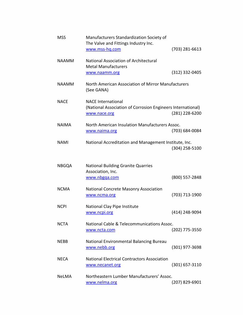
MSS Manufacturers Standardization Society of The Valve and Fittings Industry Inc. www.mss-hq.com (703) 281-6613 NAAMM National Association of Architectural Metal Manufacturers www.naamm.org (312) 332-0405 NAAMM North American Association of Mirror Manufacturers (See GANA) NACE NACE International (National Association of Corrosion Engineers International) www.nace.org (281) 228-6200 NAIMA North American Insulation Manufacturers Assoc. www.naima.org (703) 684-0084 NAMI National Accreditation and Management Institute, Inc. (304) 258-5100 NBGQA National Building Granite Quarries Association, Inc. www.nbgqa.com (800) 557-2848 NCMA National Concrete Masonry Association www.ncma.org (703) 713-1900 NCPI National Clay Pipe Institute www.ncpi.org (414) 248-9094 NCTA National Cable & Telecommunications Assoc. www.ncta.com (202) 775-3550 NEBB National Environmental Balancing Bureau www.nebb.org (301) 977-3698 NECA National Electrical Contractors Association www.necanet.org (301) 657-3110 NeLMA Northeastern Lumber Manufacturers’ Assoc. www.nelma.org (207) 829-6901

NEMA National Electrical Manufacturers Association www.nema.org (703) 841-3200 NETA InterNational Electrical Manufacturers Assoc. www.netaworld.org (303) 697-8441 NFPA National Fire Protection Association (800) 344-3555 www.nfpa.org (617) 770-3000 NFRC National Fenestration Rating Council www.nfrc.org (301) 589-6372 NGA National Glass Association www.glass.org (703) 442-4890 NHLA National Hardwood Lumber Association (800) 933-0318 www.natharwood.org (901) 377-1818 NLGA National Lumber Grades Authority www.nlga.org (604) 524-2393 NOFMA National Oak Flooring Manufacturers Assoc. www.nofma.org (901) 526-5016 NRCA National Roofing Contractors Association (800) 323-9545 www.nrca.net (847) 299-9070 NRMCA National Ready Mixed Concrete Association (888) 846-7622 www.nrmca.org (301) 587-1400 NSA National Stone Association (See NSSGA) NSF NSF International (National Sanitation Foundation International) www.nsf.org (800) 673-6275 (734) 769-8010 NSSGA National Stone, Sand & Gravel Association (Formerly: NSA – National Stone Assoc.) (800) 342-1415 www.nssga.org (703) 525-8788

NTMA National Terrazzo and Mosaic Association, Inc. www.ntma.com (800) 323-9736 (703) 779-1022 NWWDA National Wood Window and Door Association (See WDMA) PCI Precast/Prestressed Concrete Institute www.pci.org (312) 786-0300 PDCA Painting and Decorating Contractors of America www.pdca.com (800) 332-7322 (703) 359-0826 PDI Plumbing & Drainage Institute (800) 589-8956 www.pdionline.org (508) 230-3516 PGI PVC Geomembrane Institute pgi-tp.ce.uiuc.edu (217)333-3929 RCSC Research Council on Structural Connections (800) 644-2400 www.boltcouncil.org (312) 670-2400 RFCI Resilient Floor Covering Institute Contact by mail only www.rfci.com RIS Redwood Inspection Service (888) 225-7339 www.calredwood.org (415) 382-0662 SAE SAE International www.sae.org (724) 776-4841 SDI Steel Deck Institute www.sdi.org (847) 462-1930 SDI Steel Door Institute www.steeldoor.org (440) 899-0010 SEFA Scientific Equipment and Furniture Assoc. www.sefalabfurn.com (516) 294-5424 SGCC Safety Glazing Certification Council www.sgcc.org (315) 646-2234

SIGMA Sealed Insulating Glass Manufacturers Assoc. (See IGMA) SJI Steel Joist Institute www.steeljoist.org (843) 626-1995 SMA Screen Manufacturers Association www.screenmfgassociation.org (561) 533-0991 SMACNA Sheet Metal and Air Conditioning Contractors’ National Association www.smacna.org (703) 803-2980 SPFA Spray Polyurethane Foam Alliance (Formerly: SPI/SPFD – The
Society of the Plastics Industry, Inc.; Spray Polyurethane Foam Division)
www.sprayfoam.org (800) 523-6154 SPIB Southern Pine Inspection Bureau (The) www.spib.org (850) 434-2611 SPI/SPFD Society of the Plastics Industry (The) Spray Polyurethane Foam
Division (See SPFA) SPRI SPRI (Single Ply Roofing Institute) www.spri.org (781) 444-0242 SSINA Specialty Steel Industry of North America (800) 982-0355 www.ssina.com (202) 342-8630 SSMA Steel Stud Manufacturers Association (Formerly: ML/SFA – Metal Lath/Steel Framing Association) www.ssma.com (312) 456-5590 SSPC SSPC: The Society for Protective Coatings (877) 281-7772 www.sspc.org (412) 281-2331 STI Steel Tank Institute www.steeltank.com (847) 438-8265

SWI Steel Window Institute www.steeltank.com (216) 241-7333 SWRI Sealant, Waterproofing, and Restoration Institute www.swrionline.org (816) 472-7974 TCA Tile Council of America, Inc. www.tileuse.com (864) 646-8453 TIA/EIA Telecommunications Industry Association/ Electronic Industries Alliance www.tiaonline.org (703) 907-7700 TPI Truss Plate Institute (608) 833-5900 TPI Turfgrass Producers International (800) 405-8873 www.turfgrasssod.org (847) 705-9898 UL Underwriters Laboratories Inc. (800) 704-4050 www.ul.com (847) 272-8800 UNI Uni-Bell PV Pipe Association www.uni-bell.org (972) 243-3902 USGBC United States Green Building Council www.usgbc.org (800) 795-1747 USITT United States Institute for Theatre Technology, Inc. (800) 938-7488 www.culturenet.ca/usitt (315) 463-6463 WASTEC Waste Equipment Technology Association (800) 424-2869 www.watec.org (202) 244-4700 CE Army Corps of Engineers www.usace.army.mil CPSC Consumer Product Safety Commission (800) 638-2772 www.cpsc.gov (301) 504-0990 DOC Department of Commerce www.doc.gov (202) 482-2000

EPA Environmental Protection Agency www.epa.gov (202) 260-2090 FAA Federal Aviation Administration www.faa.gov (202) 366-4000 FDA Food and Drug Administration www.fda.gov (888) 463-6332 GSA General Services Administration www.gsa.gov (202) 708-5082 HUD Department of Housing and Urban Development www.hud.gov (202) 708-1112 LBL Lawrence Berkeley Laboratory
(See LBNL) LBNL Lawrence Berkeley National Laboratory www.lbl.gov (510) 486-5605 NCHRP National Cooperative Highway Research Program (See TRB) NIST National Institute of Standards and Technology www.nist.gov (301) 975-6478 OSHA Occupational Safety & Health Administration www.osha.gov (800) 321-6742 PBS Public Building Service (See GSA) RUS Rural Utilities Service (See USDA) (202) 720-9540 TRB Transportation Research Board www.nas.edu/trb (202) 334-2934 USDA Department of Agriculture www.usda.gov (202) 720-2791

USPS Postal Service www.usps.com (202) 268-2000
D. State Government Agencies: Where abbreviations and acronyms are used in
Specifications or other Contract Documents, they shall mean the recognized name of the entities in the following list. Names, telephone numbers, and Web-site addresses are subject to change and are believed to be accurate and up-to-date as of the date of the Contract Documents.
CAPUC (See CPUC) CBHF State of California, Department of Consumer Affairs Bureau of Home Furnishings and Thermal Insulation (800) 952-5210 www.daca.ca.gov/bhfti (916) 574-2041 CPUC California Public Utilities Commission www.cpuc.ca.gov (415) 703-2782 TFS Texas Forest Service Forest Products Laboratory //txforestservice.tamu.edu (936) 639-8180
PART 2 – PRODUCTS (Not Used) PART 3 – EXECUTION (Not Used)
END OF SECTION

SECTION 01500
TEMPORARY FACILITIES AND CONTROLS
PART 1 – GENERAL 1.01 SUMMARY
A. This Section includes requirements for temporary facilities and controls, including temporary utilities, support facilities, and security and protection facilities.
B. See Division 1 Section “Execution Requirements” for progress cleaning
requirements.
C. See Division 2 Section “Tree Protection and Trimming” for tree and plant protection.
D. As agreed to with Owner, and prior to demolition, Lewis House on-site may be
available for General Contractor’s use as a job office. 1.02 DEFINITIONS
A. Permanent Enclosure: As determined by Architect, permanent or temporary roofing is complete, insulted, and weathertight; exterior walls are insulated and weathertight; and all openings are closed with permanent construction or substantial temporary closures.
1.03 SUBMITTALS
A. Temporary Utility Reports: Submit reports of tests, inspections, meter readings, and similar procedures performed on temporary utilities.
1.04 QUALITY ASSURANCE
A. Standards: Comply with ANSI A10.6, NECA’s “Temporary Electrical Facilities,” and NFPA 241.
1. Electric Service: Comply with NECA, NEMA, and UL standards and
regulations for temporary electric service. Install service to comply with NFPA 70.

B. Tests and Inspections: Arrange for authorities having jurisdiction to test and inspect each temporary utility before use. Obtain required certifications and permits.
1.05 PROJECT CONDITIONS
A. Temporary Utilities: At earliest feasible time, when acceptable to Owner, change over from use of temporary service to use of permanent service.
1. Temporary Use of Permanent Facilities: Installer of each permanent
service shall assume responsibility for operation, maintenance, and protection of each permanent service during its use as a construction facility before Owner’s acceptance, regardless of previously assigned responsibilities.
B. Conditions of Use: The following conditions apply to use of temporary services and facilities by all parties engaged in the Work:
2. Keep temporary services and facilities clean and neat.
3. Relocate temporary services and facilities as required by progress of the
Work. 1.06 SUSTAINABLE BUILDING REQUIREMENTS
See Section 01011 for sustainable building requirements affecting the work of this Section.
PART 2 – PRODUCTS 2.01 MATERIALS
A. General: Provide new materials. Undamaged, previously used materials in serviceable condition may be used if approved by Architect. Provide materials suitable for use intended.
B. Pavement: Comply with Division 2 pavement Sections.
C. Portable Chain-Link Fencing: Minimum 2-inch 9-gage, galvanized steel, chain-link
fabric fencing; minimum 6 feet high with galvanized steel pipe posts; minimum 2-3/8 inch OD line posts and 2-7/8 inch OD corner and pull posts, with 1-5/8 inch OD top and bottom rails. Provide concrete or galvanized steel bases for supporting posts.

D. Lumber and Plywood: Comply with requirements in Division 6 Section “Miscellaneous Carpentry.”
E. Gypsum Board: ASTM C 36, minimum ½ inch thick by 48 inches wide by
maximum available lengths; regular-type panels with tapered edges.
F. Insulation: Unfaced mineral-fiber blanket, manufactured from glass, with maximum flame-spread and smoke-developed indices of 25 and 50 respectively.
G. Tarpaulins: Fire-resistive labeled with flame-spread rating of 15 or less.
H. Water: Potable.
2.02 EQUIPMENT
A. Field Offices: Prefabricated, mobile units, or job-built construction with lockable entrances, operable windows, and serviceable finishes; heated and air conditioned; on foundations adequate for normal loading.
B. Fire Extinguishers: Hand carried, portable, UL rated. Provide class and
extinguishing agent as indicated or a combination or extinguishers of NFPA-recommended classes for exposures.
1. Comply with NFPA 10 and NFPA 241 for classification, extinguishing
agent, and size required by location and class of fire exposure.
C. Self-Contained Toilet Units: Single-occupant units of chemical, vented; fully enclosed with a glass-fiber-reinforced polyester shell or similar non-absorbent material.
D. Drinking-Water Fixtures: Drinking-water fountains or containerized, tap-
dispenser, bottled-water, drinking-water units, including paper cup supply.
1. Where power is accessible, provide electric water coolers to maintain dispensed water temperature at 45 to 55 deg F.
E. Heating Equipment: Unless Owner authorizes use of permanent heating system,
provide vented, self-contained, liquid-propane-gas or fuel-oil heaters with individual space thermostatic control.
1. Use of gasoline-burning space heaters, open-flame heaters, or
salamander-type heating units is prohibited.

2. Heating Units: Listed and labeled, by a testing agency acceptable to authorities having jurisdiction, and marked for intended use for type of fuel being consumed.
F. Electrical Outlets: Properly configured, NEMA-polarized outlets to prevent
insertion of 110-to 120-V plugs into higher-voltage outlets; equipped with ground-fault circuit interrupters, reset button, and pilot light.
G. Power Distribution System Circuits: Where permitted and overhead and
exposed for surveillance, wiring circuits, not exceeding 125-V ac, 20-A rating, and lighting circuits may be non-metallic sheathed cable.
PART 3 – EXECUTION 3.01 INSTALLATION, GENERAL
A. Locate facilities where they will serve Project adequately and result in minimum interference with performance of the Work. Relocate and modify facilities as required.
B. Provide each facility ready for use when needed to avoid delay. Maintain and
modify as required. Do no remove until facilities are no longer needed or are replaced by authorized use of completed permanent facilities.
3.02 TEMPORARY UTILITY INSTALLATION
A. General: Engage appropriate local utility company to install temporary service or connect to existing service. Where utility company provides only part of the service, provide the remainder with matching, compatible materials and equipment. Comply with utility company recommendations.
1. Arrange with utility company, Owner, and exiting users for time when
service can be interrupted, if necessary, to make connections for temporary services.
2. Provide adequate capacity at each stage of construction. Before
temporary utility is available, provide trucked-in services.
3. Obtain easements to bring temporary utilities to Project site where Owner’s easements cannot be used for that purpose.

B. Sewers and Drainage: If sewers are available, provide temporary connections to remove effluent that can be discharged lawfully. If sewers are not available or cannot be used, provide drainage ditched, dry wells, stabilization ponds, and similar facilities. If neither sewers nor drainage facilities can be lawfully used for discharge of effluent, provide containers to remove and dispose of effluent off-site in a lawful manner.
1. Filter out excessive soil, construction debris, chemicals, oils, and similar
contaminants that might clog sewers or pollute waterways before discharge.
2. Connect temporary sewers to municipal system as directed by sewer
department officials.
3. Maintain temporary sewers and drainage facilities in a clean, sanitary condition. After heavy use, restore normal conditions promptly.
4. Provide temporary filter beds, settlement tanks, separators, and similar
devices to purify effluent to levels acceptable to authorities having jurisdiction.
C. Sanitary Facilities: Provide temporary toilets, wash facilities, and drinking-water
fixtures. Comply with regulations and health codes for type, number, location, operation, and maintenance of fixtures and facilities.
1. Disposable Supplies: Provide toilet tissue, paper towels, paper cups, and
similar disposable materials for each facility. Maintain adequate supply. Provide covered waste containers for disposal of used material.
2. Toilets: install self-contained toilet units. Shield toilets to ensure privacy.
3. Wash Facilities: Install wash facilities supplied with potable water at
convenient locations for personnel who handle materials that require wash up. Dispose of drainage properly. Supply cleaning compounds appropriate for each type of material handled.
D. Heating and Cooling: Provide temporary heating and cooling required by
construction activities for curing or drying of completed installations or for protecting installed construction from adverse effects of low temperatures or high humidity. Select equipment from that specified that will not have a harmful effect on completed installations or elements being installed.

1. Maintain a minimum temperature of 50 deg F in permanently enclosed portions of building for normal construction activities, and 65 deg F for finishing activities and areas where finished Work has been installed.
E. Ventilation and Humidity Control: Provide temporary ventilation required by
construction activities for curing or drying of completed installations or for protecting installed construction from adverse effects of high humidity. Select equipment from that specified that will not have a harmful effect on completed installations or elements being installed. Coordinate ventilation requirements to produce ambient condition required and minimize energy consumption.
F. Electric Distribution: Provide receptacle outlets adequate for connection of
power tools and equipment.
1. Provide waterproof connectors to connect separate lengths of electrical power cords if single lengths will not reach areas where construction activities are in progress. Do not exceed safe length-voltage ratio.
G. Lighting: Provide temporary lighting with local switching that provides adequate
illumination for construction operations and traffic conditions.
1. Install and operate temporary lighting that fulfills security and protection requirements without operating entire system.
H. Telephone Service: Provide temporary telephone service throughout
construction period for common-use facilities used by all personnel engaged in construction activities. Install separate telephone line for each field office and first-aid station.
1. Provide additional telephone lines for the following:
2. At each telephone, post a list of important telephone numbers, including
police and fire departments, ambulance service, Contractor’s home office, Architect’s office, Engineer’s offices, Owner’s office, and principal subcontractors’ field and home offices.
3.03 SUPPORT FACILITIES INSTALLATION
A. General: Comply with the following:
1. Locate field office, storage sheds, sanitary facilities, and other temporary construction and support facilities for easy access.
2. Comply with NFPA 241.

3. Maintain support facilities until near Substantial Completion. Remove before Substantial Completion. Personnel remaining after Substantial Completion will be permitted to use permanent facilities, under conditions acceptable to Owner.
B. Temporary Roads and Paved Areas: Construct and maintain temporary roads
and paved areas adequate to support loads and to withstand exposure to traffic during construction period.
1. Provide dust-control treatment that is non-polluting and non-tracking.
Reapply treatment as required to minimize dust.
C. Dewatering Facilities and Drains: Comply with requirements in applicable Division 2 Sections for temporary drainage and dewatering facilities and operations not directly associated with construction activities included in individual Sections. Where feasible, use same facilities. Maintain Project site, excavations, and construction free of water.
D. Project Identification and Temporary Signs: Prepare Project identification and
other signs as directed. Install signs to inform public and persons seeking entrance to Project. Do not permit installation of unauthorized signs.
1. Engage an experienced sign company for Project identification signs.
2. Prepare temporary signs to provide directional information to
construction personnel and visitors.
E. Waste Disposal Facilities: Provide waste-collection containers in sizes adequate to handle waste from construction operations. Containerize and clearly label hazardous, dangerous, or unsanitary waste materials separately from other waste. Comply with Division 1 Section “Execution Requirements” for progress cleaning requirements.
1. If required by authorities having jurisdiction, provide separate containers,
clearly labeled, for each type of waste material to be deposited.
2. Develop a waste management plan for Work performed on Project. Indicate types of waste materials Project will produce and estimate quantities of each type. Provide detailed information for on-site waste storage and separation of recyclable materials. Provide information on destination of each type of waste material and means to be used to dispose of all waste materials.

F. Lifts and Hoists: Provide facilities for hoisting materials and personnel. Truck cranes and similar devices used for hoisting materials are considered “tools and equipment” and not temporary facilities.
G. Temporary Stairs: Until permanent stairs are available, provide temporary stairs where ladders are not adequate. Cover finished, permanent stairs with protective covering of plywood or similar material so finishes will be undamaged at time of acceptance.
3.04 SECURITY AND PROTECTION FACILITIES INSTALLATION
A. Environmental Protection: Provide protection, operate temporary facilities, and conduct construction in ways and by methods that comply with environmental regulations and that minimize possible air, waterway, and subsoil contamination or pollution or other undesirable effects. Avoid using tools and equipment that produce harmful noise. Restrict use of noisemaking tools and equipment to hours that will minimize disruption of campus activities.
B. Stormwater Control: Provide earthen embankments and similar barriers in and
around excavations and subgrade construction, sufficient to prevent flooding by runoff of stormwater from heavy rains.
C. Pest Control: Before deep foundation work has been completed, retain a local
exterminator or pest-control company to recommend practices to minimize attraction and harboring of rodents, roaches, and other pests. Engage this pest-control service to perform extermination and control procedures at regular intervals so Project will be free of pests and their residues at Substantial Completion. Obtain extended warranty for Owner. Perform control operations lawfully, using environmentally safe materials.
D. Tree and Plant Protection: See Division 2 Section “Tree Protection and
Trimming.”
E. Site Enclosure Fence: Before construction operations begin, install enclosure fence with lockable entrance gates. Locate where indicated, or enclose entire Project site or portion determined sufficient to accommodate construction operations. Install in a manner that will prevent people, dogs, and other animals from easily entering site except by entrance gates.
1. Set portable chain-link fence posts in concrete bases.
2. Provide gates in sizes and at location necessary to accommodate delivery
vehicles and other construction operations.

3. Maintain security by limiting number of keys and restricting distribution to authorized personnel. Provide Owner with one (1) set of keys.
F. Security Enclosure and Lockup: Install substantial temporary enclosure around
partially completed areas of construction. Provide lockable entrances to prevent unauthorized entrance, vandalism, theft, and similar violations of security.
G. Barricades, Warning Signs, and Lights: Comply with standards and code
requirements for erecting structurally adequate barricades. Paint with appropriate colors, graphics, and warning signs to inform personnel and public of possible hazard. Where appropriate and needed, provide lighting, including flashing red or amber lights.
H. Temporary Enclosures: Provide temporary enclosures for protection of
construction, in progress and completed, from exposure, foul weather, other construction operations, and similar activities. Provide temporary weathertight enclosure for building exterior.
1. Where heating and cooling is needed and permanent enclosure is not
complete, provide insulated temporary enclosures. Coordinate enclosure with ventilating and material drying or curing requirements to avoid dangerous conditions and effects.
2. Vertical Openings: Close openings of 25 sq. ft. or less with plywood or
similar materials.
3. Horizontal Openings: Close openings in floor or roof decks and horizontal surfaces with load-bearing, wood-framed construction.
4. Install tarpaulins securely using fire-retardant-treated wood framing and
other materials.
I. Temporary Fire Protection: Until fire-protection needs are supplied by permanent facilities, install and maintain temporary fire-protection facilities of types needed to protect against reasonably predictable and controllable fire losses. Comply with NFPA 241.
1. Provide fire extinguishers, installed on walls on mounting brackets, visible
and accessible from space being served, with sign mounted above.
a. Locate fire extinguishers where convenient and effective for their intended purpose; provide not less than one (1) extinguisher on each floor at or near each usable stairwell.

2. Store combustible materials in containers in fire-safe locations.
3. Maintain unobstructed access to fire extinguishers, fire hydrants, temporary fire-protection facilities, stairways, and other access routes for firefighting. Prohibit smoking in hazardous fire-exposure areas.
4. Supervise welding operations, combustion-type temporary heating units,
and similar sources of fire ignition.
5. Permanent Fire Protection: At earliest feasible date in each area of Project, complete installation of equipment fire-protection facility, including connected services, and place into operation and use. Instruct key personnel on use of facilities.
6. Develop and supervise an overall fire-prevention and first-aid fire-
protection program for personnel at Project site. Review needs with local fire department and establish procedures to be followed. Instruct personnel in methods and procedures. Post warnings and information.
7. Provide hoses for fire protection of sufficient length to reach construction
areas. Hang hoses with a warning sign stating that hoses are for fire-protection purposes only and are not to be removed. Match hose size with outlet size and equip with suitable nozzles.
3.05 OPERATION, TERMINATION, AND REMOVAL
A. Supervision: Enforce strict discipline in use of temporary facilities. To minimize waste and abuse, limit availability of temporary facilities to essential and intended uses.
B. Maintenance: Maintain facilities in good operating condition until removal.
Protect from damage caused by freezing temperatures and similar elements.
1. Maintain operation of temporary enclosures, heating, cooling, humidity control, ventilation, and similar facilities on a 24-hour basis where required to achieve indicated results and to avoid possibility of damage.
2. Prevent water-filled piping from freezing. Maintain markers for
underground lines. Protect from damage during excavation operations.
C. Temporary Facility Changeover: Except for using permanent fire protection as soon as available, does not change over from using temporary security and protection facilities to permanent facilities until Substantial Completion.

D. Termination and Removal: Remove each temporary facility when need for its service has ended, when it has been replaced by authorized use of a permanent facility, or no later than Substantial Completion. Complete or, if necessary, restore permanent construction that may have been delayed because of interference with temporary facility. Repair damaged Work, clean exposed surfaces, and replace construction that cannot be satisfactorily repaired.
1. Materials and facilities that constitute temporary facilities are the
property of Contractor. Owner reserves right to take possession of Project identification signs.
2. At Substantial Completion, clean and renovate permanent facilities used
during construction period. Comply with final cleaning requirements in Division 1 Section “Closeout Procedures.”
END OF SECTION

SECTION 01505
CONSTRUCTION WASTE MANAGEMENT PART 1 – GENERAL 1.01 SUMMARY
A. The Owner has established that this Project generate the least amount of waste possible and that processes that ensure the generation of as little waste as possible due to over packaging, improper storage, error, poor planning, breakage, mishandling, contamination, or other factors shall be employed.
B. Of the inevitable waste that is generated, as many of the waste materials as
economically feasible shall be reused, salvages, or recycled utilizing available programs and facilities in the immediate region. Waste disposal in landfills shall be minimized.
C. The Contractor shall develop, for the Architect’s review, a Waste Management
Plan for this Project.
D. The goal has been established to meet USGBC LEED certification criteria to limit waste generation, and to divert a minimum of 75% of total project waste from landfill.
1.02 WASTE MANAGEMENT PLAN
A. Draft Waste Management Plan: Within ten (10) calendar days after receipt of Notice of Award of Contract, or prior to any waste removal, whichever occurs sooner, the Contractor shall submit to the Owner and Architect a Draft Waste Management Plan. The Draft Plan shall contain the following:
1. Analysis of the proposed job site waste to be generated, including types
and quantities.
2. Landfill options: The name of the landfill(s) where trash will be disposed of, the applicable landfill tipping fee(s), and the projected cost of disposing of all Project waste in the landfill(s).
3. Alternatives to Landfilling: Prepare a list of each material proposed to be
salvaged, reused, or recycled during the course of the Project, the proposed local market for each material (consult local integrated waste management programs), and the estimated net cost savings or additional

costs resulting from separating and recycling (versus land filling) each material. “Net” means that the following have been subtracted from the cost of separating and recycling:
a. Revenue from the sale of recycled or salvaged materials listed
by type and weights in tons.
b. Landfill tipping fees saved due to diversion of materials from the landfill.
4. List of materials to be recycled, reused or returned to manufacturer shall
include, but not be limited to, the following materials:
a. Cardboard, paper, packaging
b. Clean dimensional wood, wood pallets
c. Plywood, OSB, and particleboard
d. Concrete Masonry Units (CMU) (concrete block)
e. Brick
f. Concrete
g. Asphalt
h. Metals from banding, stud trim, ductwork, piping, rebar, roofing, other trim, steel, iron, galvanized sheet steel, stainless steel, aluminum, copper, zinc, lead, brass and bronze.
i. Gypsum Drywall
j. Carpet and pad
k. Paint
l. Rigid Foam
m. Glass
n. Plastics
o. Land clearing debris

p. Acoustical ceiling materials.
B. Waste Management Plan (Final): Once the Owner has determined which of the recycling options addressed in the draft Waste Management Plan are acceptable, the Contractor shall submit, within ten (10) calendar days, a Waste Management Plan. The Waste Management Plan shall contain the following:
1. Analysis of the proposed job site waste to be generated, including types,
quantities, and when during the job each type will be generated.
2. Alternatives to Landfilling: A list of the waste materials from the Project that will be separated for reuse, salvage, or recycling.
a. Report revenue from the sale of recycled or salvaged materials
listed by type, and weight in tons.
3. Landfill options: The name of the landfill(s) where trash will be disposed of, the applicable landfill tipping fee(s), and the projected cost of disposing of all Project waste in the landfill(s).
4. Materials Handling Procedures: A description of the means by which any
waste materials identified in Subparagraph 2 (“Alternatives to Landfilling”) above will be protected from contamination, and a description of the means to be employed in recycling the above materials consistent with requirements for acceptance by designated facilities.
5. Transportation: A description of the means of transportation of the
recyclable materials (whether materials will be site-separated and self-hauled to designated centers, or whether mixed materials will be collected by waste hauler and removed from the site) and destination of materials. Provide an estimate of how often bins will need to be emptied.
6. Suppliers: A description of the means by which materials and equipment
will be delivered to the site. Provide an estimate of packaging materials generated and whether suppliers will eliminate or take back packaging.
C. Waste Management Plan Implementation:
1. Manager: The Construction Superintendent (See Section 01100
Summary, Subparagraph 1.1, C, 2).

2. Distribution: Post a copy of this Waste Management Plan in a conspicuous place at the Site, and distribute copies to the Job-Site Foreman, each Subcontractor, and the Architect.
3. Instruction: Provide on-site instruction of appropriate separation,
handling, and recycling, salvage, reuse, and return methods to be used by all parties at the appropriate stages of the Project.
4. Meetings: Conduct Construction Waste Management meetings.
Meetings shall include subcontractors affected by the Waste Management Plan. At a minimum, waste management goals and issues shall be discussed at the following meetings:
a. Pre-bid meeting.
b. Pre-construction meeting.
c. Regular job-site meetings.
5. Separation facilities: Lay-out and label a specific area to facilitate
separation of materials for potential recycling, salvage, reuse, and return. Recycling and waste bin areas shall be kept neat and clean and clearly marked in order to avoid contamination of materials.
6. Hazardous wastes: Hazardous wastes shall be separated, stored, and
disposed of according to local regulations.
7. Applications for Progress Payments: Submit with each Application for Progress Payment, a Summary of Waste Generated and Recycled by the Project. Failure to submit this information shall render the Application for Payment incomplete and shall delay Progress Payment. The Summary shall contain the following information:
a. The amount in tons of material landfilled from the Project, the
identity of the landfill, the total amount of tipping fees paid at the landfill, and the total disposal cost. Include manifests, weight tickets, receipts and invoices.
b. For each material recycled, reused, or salvaged from the Project,
include the amount in tons, the date removed from the job site, the receiving party, the transportation cost, the amount of any money paid or received for the recycled or salvaged material, and the net total cost or savings of salvage or recycling each

material. Attach manifests, weight tickets, receipts, and or invoices.
1.03 SUBMITTALS
A. Make submittals in accordance with Section 01330.
B. Within fourteen (14) days after receipt of Notice of Award and prior to any waste removal by the Contractor from the Project, the Contractor shall develop and submit to the Owner for review a draft Construction Waste Management Plan.
1. The Waste Management Plan shall include:
a. Types and estimated quantities (where reasonably available) of
salvageable materials that are expected to be generated during demolition. Calculations may be based on dry weight or volume, but must be consistent throughout.
b. The method to be used to recycle these materials. Methods
shall include one or more of the following options: contracting with a demolition specialist to salvage all or most of materials generated, selective salvage as part of demolitions contractor’s work, or reuse of materials on site or in new construction. Use the recycling rates and list of material accepted provided King County Solid Waste Division Report of Co-mingled Recycling Facilities to determine which waste materials on this project will be source-separated or co-mingles in each construction phase. See Section 1.2.B.1 for where to view the report online.
c. Types and estimated quantities (where reasonably available) of
recyclable materials expected to be generated during construction in significant amounts including but not limited to wood, concrete, metals, cardboard, and drywall. Calculations may be based on weight or volume, but must be consistent throughout.
d. The method to be used to recycle these materials. Methods
shall include one (1) or more of the following options: requiring subcontractors to take materials back for recycling at a permitted facility, contracting with a full service recycling service to recycle all or most materials at a permitted facility, or processing or reusing materials on-site. Use the recycling rates and list of material accepted provided King County Solid Waste Division Report of Co-mingled Recycling Facilities to determine
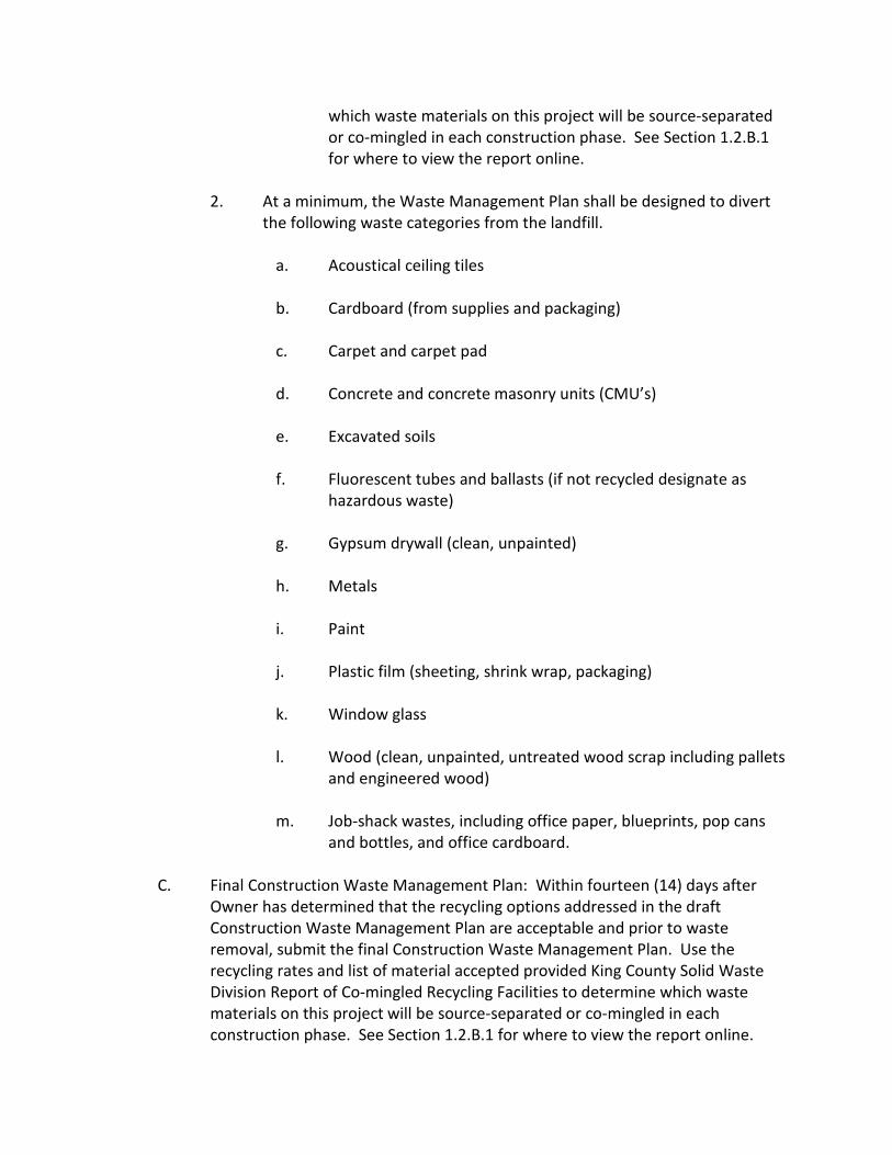
which waste materials on this project will be source-separated or co-mingled in each construction phase. See Section 1.2.B.1 for where to view the report online.
2. At a minimum, the Waste Management Plan shall be designed to divert
the following waste categories from the landfill.
a. Acoustical ceiling tiles
b. Cardboard (from supplies and packaging)
c. Carpet and carpet pad
d. Concrete and concrete masonry units (CMU’s)
e. Excavated soils
f. Fluorescent tubes and ballasts (if not recycled designate as hazardous waste)
g. Gypsum drywall (clean, unpainted)
h. Metals
i. Paint
j. Plastic film (sheeting, shrink wrap, packaging)
k. Window glass
l. Wood (clean, unpainted, untreated wood scrap including pallets
and engineered wood)
m. Job-shack wastes, including office paper, blueprints, pop cans and bottles, and office cardboard.
C. Final Construction Waste Management Plan: Within fourteen (14) days after
Owner has determined that the recycling options addressed in the draft Construction Waste Management Plan are acceptable and prior to waste removal, submit the final Construction Waste Management Plan. Use the recycling rates and list of material accepted provided King County Solid Waste Division Report of Co-mingled Recycling Facilities to determine which waste materials on this project will be source-separated or co-mingled in each construction phase. See Section 1.2.B.1 for where to view the report online.

D. Progress Reports: Submit with each Application for Payment a summary of construction waste generated. Include the following:
1. For each material recycled, reused, or salvaged from the Project, the
amount (in tons) or cubic yards, the receiving party, and the net total costs or savings of salvage or recycling the material. Attached manifests, weight tickets receipts or invoices. For co-mingled materials, the Contractor shall include the co-mingled CDL recycling rate of the receiving facility.
2. The amount (in tons or cubic yards) of material disposed of as garbage
from the Project, the location of the Receiving Facility, and the total disposal cost. Include manifests, weight tickets, receipt, and invoices.
3. The Contractor shall be responsible for providing such information
whether directly involved in recycling the materials or not (whether the Contractor performs recycling tasks or hires or requires others to do so, such as subcontractors to haul their own drywall or metal).
E. Final Report: The Contractor shall submit within fourteen (14) calendar days of
completing the project a final waste management report of waste generated at the Project. The final report shall be submitted on a form acceptable to the Owner’s Project Manager and shall contain the following information:
1. For each material recycled, reused, or salvaged from the Project, the total
amount (in tons or cubic yards), the receiving party, and the net total cost or savings of salvage or recycling the material. Attached manifests, weight tickets receipts or invoices. For co-mingled materials, the Contractor shall include the co-mingled CDL recycling rate of the receiving facility.
2. The total amount (in tons or cubic yard of material) of material disposed
of as garbage from the Project, the location of the Receiving Facility, and the total disposal cost. Include manifests, weight tickets, receipt, and invoices.
3. The Contractor shall be responsible for providing such information
whether directly involved in recycling the materials or not (whether the Contractor performs recycling tasks or hires or requires other to do so, such as subcontractors to haul their own drywall or metal).
F. LEED Documentation: Provide documentation that the requirements of LEED
Credit MR 2.2 have been met.

1.04 SUSTAINABLE BUILDING REQUIREMENTS
See Section 01011 for sustainable building requirements affecting the work of this Section.
END OF SECTION

SECTION 01600
PRODUCT REQUIREMENTS
PART 1 – GENERAL 1.01 RELATED DOCUMENTS
A. Drawings and general provisions of the Contract, including General and Supplementary Conditions and other Division 1 Specification Sections, apply to this Section.
1.02 SUMMARY
A. This Section includes the following administrative and procedural requirements: selection of products for use in Project; product delivery, storage, and handling; manufacturers’ standard warranties on products; special warranties; product substitutions; and comparable products.
B. Related Sections include the following:
1. Division 1 Section “Alternates” for products selected under an alternate.
2. Division 1 Section “References” for applicable industry standards for
products specified.
3. Division 1 Section “Closeout Procedures” for submitting warranties for contract closeout.
4. Divisions 2 through 16 Sections for specific requirements for warranties
on products and installations specified to be warranted. 1.03 DEFINITIONS
A. Products: Items purchased for incorporating into the Work, whether purchased for Project or taken from previously purchased stock. The term “product” includes the terms “material,” “equipment,” “system,” and terms of similar intent.
1. Named Products: Items identified by manufacturer’s product name,
including make or model number or other designation, shown or listed in

manufacturer’s published product literature that is current as of date of the Contract Documents.
2. New Products: Items that have not previously been incorporated into
another project or facility. Products salvaged or recycled from other projects are not considered new products.
3. Comparable Product: Product that is demonstrated and approved
through submittal process, or where indicated as a product substitution, to have the indicated qualities related to type, function, dimension, in-service performance, physical properties, appearance, and other characteristics that equal or exceed those of specified product.
B. Substitutions: Changes in products, materials, equipment, and methods of
construction from those required by the Contract Documents and proposed by Contractor.
C. Basis-of-Design Product Specification: Where a specific manufacturer’s product
is named and accompanied by the words “basis-of-design,” including make or model number or other designation, to establish the significant qualities related to type, function, dimension, in-service performance, physical properties, appearance, and other characteristics for purposes of evaluating comparable products of other named manufacturers.
D. Manufacturer’s Warranty: Preprinted written warranty published by individual
manufacturer for a particular product and specifically endorsed by manufacturer to Owner.
E. Special Warranty: Written warranty required by or incorporated into the
Contract Documents, either to extend time limit provided by manufacturer’s warranty or to provide more rights for Owner.
1.04 SUBMITTALS
A. Substitution Requests: Submit three (3) copies of each request for consideration. Identify product or fabrication or installation method to be replaced. Include Specification Section number and title and Drawing numbers and titles.
1. Substitution Request Form: Use form provided at end of Section.

2. Documentation: Show compliance with requirements for substitutions and the following, as applicable:
a. Statement indicating why specified material or product cannot
be provided.
b. Coordination information, including a list of changes or modifications needed to other parts of the Work and to construction performed by Owner and separate contractors that will be necessary to accommodate proposed substitution.
c. Product Data, including drawings and descriptions of products
and fabrication and installation procedures.
d. Samples, where applicable or requested.
e. List of similar installation for completed projects with project names and addresses and names and addresses of architects and owners.
f. Research/evaluation reports evidencing compliance with
building code in effect for Project, from a model code organization acceptable to authorities having jurisdiction.
g. Detailed comparison of Contractor’s Construction Schedule
using proposed substitution with products specified for the Work, including effect on the overall Contract Time. If specified product of method or construction cannot be provided within the Contract Time, include letter from manufacturer, on manufacturer’s letterhead, stating lack of availability or delays in deliver.
h. Cost information, including a proposal of change, if any, in the
Contract Sum.
i. Contractor’s certification that proposed substitution complies with requirements in the Contract Documents and is appropriate for applications indicated.
j. Contractor’s waiver of rights to additional payment or time that
may subsequently become necessary because of failure of proposed substitution to produce indicated results.

3. Architect’s Action: If necessary, Architect will request additional information or documentation for evaluation within one (1) week of receipt of a request for substitution. Architect will notify Contractor an acceptance or rejection of proposed substitution within fifteen (15) days of receipt of request, or seven (7) days of receipt of additional information or documentation, whichever is later.
a. Form of Acceptance: Change Order.
b. Use product specified if Architect cannot make a decision on use
of a proposed substitution within time allocated.
B. Basis-of-Design Product Specification Submittal: Comply with requirements in Division 1 Section “Submittal Procedures.” Show compliance with requirements.
1.05 QUALITY ASSURANCE
A. Compatibility of Options: If Contractor is given option of selecting between two or more products for use on Project, product selected shall be compatible with products previously selected, even if previously selected products were also options.
1.06 PRODUCT DELIVER, STORAGE, AND HANDLING
A. Deliver, store, and handle products using means and methods that will prevent damage, deterioration, and loss, including theft. Comply with manufacturer’s written instructions.
1. Schedule delivery to minimize long-term storage at Project site and to
prevent overcrowding of the construction site. 2. Coordinate delivery with installation time to ensure minimum holding
time for items that are flammable, hazardous, easily damage, or sensitive to deterioration, theft, and other losses.
3. Deliver products to Project site in an undamaged condition in
manufacturer’s original sealed container or other packaging system, complete with labels and instruction for handling, storing, unpacking, protecting, and installing.
4. Inspect products on delivery to ensure compliance with the Contract
Documents and to ensure that products are undamaged and property protected.

5. Store products to allow for inspection and measurement of quantity or counting of units.
6. Store materials in manner that will not endanger Project structure.
7. Store products that are subject to damage by the elements, under cover
in a weathertight enclosure above ground, with ventilation adequate to prevent condensation.
8. Comply with product manufacturer’s written instructions for
temperature, humidity, ventilation, and weather-protection requirements for storage.
9. Protect stored products from damage.
B. Storage: Provide a secure location and enclosure at Project site for storage of
materials and equipment by Owner’s construction forces. Coordinate location with Owner.
1.07 PRODUCT WARRANTIES
A. Warranties specified in other Sections shall be in addition to, and run concurrent wit, other warranties required by the Contract Documents. Manufacturer’s disclaimers and limitations on product warranties do not relieve Contractor of obligations under requirements of the Contract Documents.
B. Special Warranties: Prepare a written document that contains appropriate
terms and identification, ready for execution. Submit a draft for approval before final execution.
1. Manufacturer’s Standard Form: Modified to include Project-specific
information and properly executed.
2. Refer to Divisions 2 through 16 Sections for specific content requirements and particular requirements for submitting special warranties.
C. Submittal Time: Comply with requirements in Division 1 Section “Closeout
Procedures.” 1.08 SUSTAINABLE BUILDING REQUIREMENTS
See Section 01011 for sustainable building requirements affecting the work of this Section.

PART 2 – PRODUCTS 2.01 PRODUCT OPTIONS
A. General Product Requirements: Provide products that comply with the Contract Documents, that are undamaged, and unless otherwise indicated, that are new at time of installation.
1. Provide products complete with accessories, trim, finish, fasteners, and
other items needed for a complete installation and indicated use and effect.
2. Standard Products: If available, and unless custom products or
nonstandard options are specified, provide standard products of types that have been produced and used successfully in similar situations on other projects.
3. Owner reserves the right to limit selection to products with warranties
not in conflict with requirements of the Contract Documents.
4. Where products are accompanied by the term “as selected,” Architect will make selection.
5. Where products are accompanied by the term “match sample,” sample
to be matched is Architect’s.
6. Descriptive, performance, and reference standard requirements in the Specifications establish “salient characteristics” of products.
B. Product Selection Procedures: Procedures for product selection include the
following:
1. Product: Where Specification paragraphs or subparagraphs titled “Product” name a single product and manufacturer, to provide the product named.
a. Substitutions may be considered, unless otherwise indicated.
2. Manufacturer/Source: Where Specification paragraphs or subparagraphs
titled “Manufacturer” or “Source” name single manufacturers or sources, provide a product by the manufacturer or from the source named that complies with requirements.
a. Substitutions may be considered, unless otherwise indicated.

3. Products: Where Specification paragraphs or subparagraphs titled “Products” introduce a list of names of both products and manufacturers, provide one (1) of the products listed that comply with requirements.
a. Substitutions may be considered, unless otherwise indicated.
4. Manufacturers: Where Specification paragraphs or subparagraphs titled
“Manufacturers” introduce a list of manufacturers’ manes, provide a product by one (1) of the manufacturers listed that complies with requirements.
a. Substitutions may be considered, unless otherwise indicated.
5. Available Products: Where Specification paragraphs or subparagraphs titled
“Available Products” introduce a list of names of both products and manufacturers, provide one of the products listed or another product that complies with requirements. Comply with provisions in “Comparable Products” Article to obtain approval for use of an unnamed product.
6. Available Manufacturers: Where Specification paragraphs or subparagraphs
titled “Available Manufacturers” introduce a list of manufacturers’ manes, provide a product by one of the manufacturers listed or another manufacturer that complies with requirements. Comply with provisions in “Comparable Products” Article to obtain approval for use of an unnamed product.
7. Product Options: Where Specification paragraphs titled “Product Options”
indicated that size, profiles, and dimensional requirements on Drawings are based on a specific product or system, provide either the specific product or system indicated or a comparable product or system by another manufacturer. Comply with provisions in “Product Substitutions” Article.
8. Basis-of-Design Products: Where Specification paragraphs or subparagraphs
titled “Basis-of-Design Products(s)” are included and also introduce or refer to a list of manufacturers’ names, provide wither the specified product or a comparable product by one of the other named manufacturers. Drawings and Specifications indicate sizes, profiles, dimensions, and other characteristics that are based on the product named. Comply with provisions in “Comparable Products” Article to obtain approval for use of an unnamed product.
a. Substitutions may be considered.

2.02 PRODUCT SUBSTITUTIONS
A. Timing: Architect will consider requests for substitution if received ten (10) days before the bid date. Requests received after that time may be considered or rejected at discretion of Architect.
B. Conditions: Architect shall coordinate with Owner prior to any approval of
substitutions. Architect will consider Contractor’s request for substitution when the following conditions are satisfied. If the following conditions are not satisfied, Architect will return requests without action, except to record non-compliance with these requirements:
1. Requested substitution offers Owner a substantial advantage in cost,
time, energy conservation, or other considerations, after deducting additional responsibilities Owner must assume. Owner’s additional responsibilities may include compensation to Architect for redesign and evaluation services, increased cost of other construction by Owner, and similar considerations.
2. Requested substitution does not require extensive revisions to the
Contract Documents.
3. Requested substitution is consistent with the Contract Documents and will produce indicated results.
4. Substitution request is fully documented and properly submitted.
5. Requested substitution will not adversely affect Contractor’s
Construction Schedule.
6. Requested substitution is compatible with other portions of the Work.
7. Requested substitution has been coordinated with other portions of the Work.
8. Requested substitution provides specified warranty.
2.03 COMPARABLE PRODUCTS
A. Where products or manufacturers are specified by name, submit the following, in addition to other required submittals, to obtain approval of an unnamed product:

1. Evidence that the proposed product does not require extensive revisions to the Contract Documents that it is consistent with the Contract Documents and will produce the indicated results, and that it is compatible with other portions of the Work.
2. Detailed comparison of significant qualities of proposed product with
those named in the Specifications. Significant qualities include attributes such as performance, weight, size, durability, visual effect, and specific features and requirements indicated.
3. Evidence that proposed product provides specified warranty.
4. List of similar installations for completed projects with project names and
addresses of Architects and Owners, if requested.
5. Samples, if requested. PART 3 – EXECUTION Not Used
END OF SECTION

SECTION 01632
VALUE ENGINEERING PRODUCT SUBSTITUTIONS
PART 1 – GENERAL 1.01 DESCRIPTION
A. This Section specifies administrative and procedural requirements for handling Requests for Substitutions made after award of the Contract.
B. Standards: Refer to Section “Definitions and Standards” for applicability of
industry standards to products specified.
C. Procedural requirements governing the Contractor’s selection of products and product options are included under Section “Material and Equipment”.
1.02 DEFINITIONS
A. Definitions used in this Article are not intended to change or modify the meaning of other terms used in the Contract Documents.
B. Substitutions: Requests for changes in products, materials, equipment, and
methods of construction required by Contract Documents proposed by the Contractor after award of the Contract are considered requests for “value engineering substitutions”. The following are not considered substitutions.
1. Revisions to Contract Documents requested by the Owner or Architect.
2. Specified options of products and construction methods included in
Contract Documents.
3. The Contractor’s determination of and compliance with governing regulations and order issued by governing authorities.
1.03 SUBMITTALS
A. Requests for value engineering substitution will be considered for review if received within thirty (30) days after commencement of the Work. Requests received after thirty (30) days may be considered or rejected at the discretion of the Architect.

B. Submit three (3) copies to the Architect and one (1) to the Owner of each Request for Substitution on the attached form and in accordance with procedures for Change Order proposals.
C. Identify the product or installation method to be replaced in each Request.
Include related specification sections and drawing numbers. Document compliance with requirements for substitutions, and the following information, as appropriate:
1. Product data, including drawings and descriptions of products,
fabrication and installation procedures.
2. Samples, where applicable or requested.
3. A comparison of significant qualities of the proposed substitution with those specified.
4. A list of changes or modifications needed to other parts of the Work and
to construction performed by the Owner and separate Contractors that will be necessary to accommodate the proposed substitution.
5. A statement indicating the substitution’s effect on the Construction
Schedule compared the Schedule without approval of the substitution. Indicate the effect of the proposed substitution on overall Contract Time.
6. Cost information, including a proposal of the net change, if any in the
Contract Sum.
7. Certification that the substitution is equal to or better in every respect to that required by Contract Documents, and that it will perform adequately in application indicated. Include Contractor’s waiver of rights to additional payment or time that may be necessary because of the substitution’s failure to perform adequately.
D. All Requests for Substitution must be made by the General or Prime Contractor.
1.04 CRITERIA FOR ACCEPTANCE FOR REVIEW
A. Value Engineering Substitutions will be accepted for review under the following conditions.
1. A substantial advantage is offered the Owner, in terms of cost, time,
energy conservation or other consideration of merit.

2. Extensive revisions to Contract Documents are not required.
3. Proposed changes are in keeping with the general intent of Contract Documents.
4. The request is timely, within specified consideration period, fully
documented and properly submitted.
B. Value Engineering Substitutions will be reviewed/considered by Architect and Owner for a lump-sum payment of $500.00.
1. This cost is exclusive of any subsequent costs for redesign, which may be
required as a result of change to the Contract Documents due to the proposed change. Additional costs shall be borne by the Contractor.
2. Payment shall be made to the Owner for reimbursement to the Architect.
1.05 ARCHITECT’S ACTION
A. Within one (1) week of receipt of the Request for Substitution, the Architect may request additional information necessary for evaluation. Within two (2) weeks of receipt of the request, or one (1) week of receipt of additional information, whichever is later, the Architect will notify the Contractor of acceptance of rejection. If a decision on use of a substitute cannot be made within the time allocated, use the product specified. Acceptance will be in for the form of a Change Order.
1.06 WAIVER OF REVIEW FEE
A. Waiver of the review fee for value engineering substitution request may be considered by the Architect an Owner when one or more of the following conditions are satisfied, as determined by the Architect.
1. The specified product or method of construction cannot be provided
within the Contract Time. The request will not be considered if the product or method cannot be provided as a result of failure to pursue the work promptly or coordinate activities properly.
2. The specified product or method of construction cannot receive
necessary approval by a governing authority, and the requested substitution can be approved.
3. The specified product or method of construction cannot be provided in a
manner that is compatible or cannot be coordinated with other

materials, and where the Contractor certifies that the substitution will overcome the condition.
4. The specified product or method of construction cannot provide a
warranty required by the Contract Documents and where the Contractor certified that the proposed substitution provides the required warranty.
B. In no event will substitution proposals, including those indicated in this article,
be accepted from the Contractor without payment. 1.07 SUBSTITUTIONS VIA SUBMITTALS
A. The Contractor’s submittal and Architect’s acceptance of shop drawings, product data, or samples that relate to construction activities not complying with Contract Documents does not constitute an acceptable or valid request for substitution, nor does it constitute approval. Work that is not in compliance with Contract Documents may be rejected, even if in accordance with reviewed submittals, without an approved substitution request.
1.08 SUSTAINABLE BUILDING REQUIREMENT
See Section 01011 for sustainable building requirements affecting the work of this Section.
PART 2 – PRODUCTS Not Used PART 3 – EXECUTION Not Used
END OF SECTION

SECTION 01700
EXECUTION REQUIREMENTS
PART 1 – GENERAL 1.01 SUMMARY
A. This Section includes general procedural requirements governing execution of the Work including, but not limited to, the following:
1. Construction layout.
2. Field engineering and surveying.
3. General installation of products.
4. Coordination of Owner-installed products.
5. Progress cleaning.
6. Starting and adjusting.
7. Protection of installed construction.
8. Correction of the Work.
B. Related Sections include the following:
1. Division 1 Section “Submittal Procedures” for submitting surveys.
2. Division 1 Section “Selective Demolition” for procedural requirements for
removal of existing construction necessary for the installation or performance of other components of the Work.
3. Division 1 Section “Closeout Procedures” for final cleaning.
1.02 QUALITY ASSURANCE
A. Land Surveyor Qualifications: A professional land surveyor who is legally qualified to practice in jurisdiction where Project is located and who is experienced in providing land-surveying services of the kind indicated.

1.03 SUSTAINABLE BUILDING REQUIREMENTS
See Section 01011 for sustainable building requirements affecting the work of this Section.
PART 2 – PRODUCTS Not Used PART 3 – EXECUTION 3.01 EXAMINATION
A. Existing Conditions: The existence and location of site improvements, utilities, and other construction indicated as existing are not guaranteed. Before beginning work, investigate and verify the existence and location of mechanical and electrical systems and other construction affecting the Work.
1. Before construction, verify the location and points of connection of utility
services.
B. Existing Utilities: The existence and location of underground and other utilities and construction indicated as existing are not guaranteed. Before beginning sitework, investigate and verify the existence and location of underground utilities and other construction affecting services.
1. Before construction, verify the location and invert elevation at points of
connection of sanitary sewer, storm sewer, and water-service piping; and underground electrical services.
2. Furnish location data for work related to Project that must be performed
by public utilities serving Project site.
C. Acceptance of Conditions: Examine substrates, areas, and conditions, with Installer or Applicator present where indicated, for compliance with requirements for installation tolerances and other conditions affecting performance. Record observations.
1. Verify compatibility with and suitability of substrates, including
compatibility with existing finishes or primers.
2. Examine roughing-in for mechanical and electrical systems to verify actual locations of connections before equipment and fixture installation.

3. Examine walls, floors, and roofs for suitable conditions where products and systems are to be installed.
4. Proceed with installation only after unsatisfactory conditions have been
corrected. Proceeding with the Work indicates acceptance of surfaces and conditions.
3.02 PREPARATION
A. Existing Utility Information: Furnish information to Owner that is necessary t o adjust, move, or relocate existing utility structures, utility poles, lines, services, or other utility appurtenances located in or affected by construction. Coordinate with authorities having jurisdiction.
B. Existing Utility Interruptions: Do not interrupt utilities serving facilities occupied
by Owner or other unless permitted under the following conditions and then only after arranging to provide temporary utility services according to requirements indicated:
1. Notify Owner not less than fourteen (14) days in advance of proposed
utility interruptions.
2. Do not proceed with utility interruptions without Owner’s written permission.
C. Field Measurements: Take field measurements as required to fit the Work
properly. Recheck measurements before installing each product. Where portions of the Work are indicated to fit to other construction, verify dimensions or other construction by field measurements before fabrication. Coordinate fabrication schedule with construction progress to avoid delaying the Work.
D. Space Requirements: Verify space requirements and dimensions of items shown
diagrammatically on Drawings.
E. Review of Contract Documents and Field Conditions: Immediately on discovery of the need for clarification of the Contract Documents, submit a request for information to Architect. Include a detailed description of problem encountered, together with recommendations for changing the Contract Documents.
3.03 CONSTRUCTION LAYOUT
A. Verification: Before proceeding to lay out the Work, verify layout information shown on Drawings, in relation to the property survey and existing benchmarks. If discrepancies are discovered, notify Architect promptly.

B. General: Engage a land surveyor to lay out the Work using accepted surveying practices.
1. Establish benchmarks and control points to set lines and levels at each
story of construction and elsewhere as needed to locate each element of Project.
2. Establish dimensions within tolerances indicated. Do not scale Drawings
to obtain required dimensions.
3. Inform installers of lines and levels to which they must comply.
4. Check the location, level and plumb, of every major element as the Work progresses.
5. Notify Architect when deviations from required lines and levels exceed
allowable tolerances.
6. Close site surveys with an error of closure equal to or less than the standard established by authorities having jurisdiction.
C. Site Improvements: Locate and lay out site improvements, including pavements,
grading fill and topsoil placement, utility slopes, and invert elevations.
D. Building Lines and Levels: Locate and lay out control lines and levels for structures, building foundations, column grids, and floor levels, including those required for mechanical and electrical work. Transfer survey markings and elevations for use with control lines and levels. Level foundations and piers from two (2) or more locations.
E. Record Log: Maintain a log of layout control work. Record deviations from
required lines and levels. Include beginning and ending dates and times of surveys, weather conditions, name and duty of each survey party member, and types of instruments and tapes used. Make the log available for reference by Architect.
3.04 FIELD ENGINEERING
A. Identification: Owner will identify existing benchmarks, control points, and property corners.
B. Reference Points: Locate existing permanent benchmarks, control points, and
similar reference points before beginning the Work. Preserve and protect permanent benchmarks and control points during construction operations.

1. Do not change or relocate existing benchmarks or control points without prior written approval of Architect. Report lost or destroyed permanent benchmarks or control points promptly. Report the need to relocate permanent benchmarks or control points to Architect before proceeding.
2. Replace lost or destroyed permanent benchmarks and control points
promptly. Base replacements on the original survey control points.
C. Benchmarks: Establish and maintain a minimum of two (2) permanent benchmarks on Project site, referenced to data established by survey control points. Comply with authorities having jurisdiction for type and size of benchmark.
1. Record benchmark locations, with horizontal and vertical data, on Project
Record Documents.
2. Where the actual location or elevation of layout points cannot be marked, provide temporary reference points sufficient to locate the Work.
3. Remove temporary reference points when no longer needed. Restore
marked construction to its original condition. 3.05 INSTALLATION
A. General: Locate the Work and components of the Work accurately, in correct alignment and elevation, as indicated.
1. Make vertical work plumb and make horizontal work level.
2. Where space is limited, install components to maximize space available
for maintenance and ease of removal for replacement.
3. Conceal pipes, ducts, and wiring in finished areas, unless otherwise indicated.
B. Comply with manufacturer’s written instructions and recommendations for
installing products in applications indicated. C. Install products at the time and under conditions that will ensure the best
possible results. Maintain conditions required for product performance until Substantial Completion.

D. Conduct construction operation so no part of the Work is subjected to damaging operations or loading in excess of that expected during normal conditions of occupancy.
E. Tools and Equipment: do not use tools or equipment that produce harmful noise
levels.
F. Anchors and Fasteners: Provide anchors and fasteners as required to anchor each component securely in place, accurately located and aligned with other portions of the Work.
1. Mounting Heights: Where mounting heights are not indicated, mount
components at heights directed by Architect.
2. Allow for building movement, including thermal expansion and contraction.
G. Joints: Make joints of uniform width. Where joint locations I n exposed work
are not indicated, arrange joints for the best visual effect. Fit exposed connections together to form hairline joints.
H. Hazardous Materials: Use products, cleaners, and installation materials that are
not considered hazardous. 3.06 PROGRESS CLEANING
A. General: Clean Project site and work areas daily, including common areas. Coordinate progress cleaning for joint use areas where more than one (1) installer has worked. Enforce requirements strictly. Dispose of materials lawfully.
1. Comply with requirements in NFPA 241 for removal of combustible waste
materials and debris.
2. Do not hold materials more than seven (7) days during normal weather or three (3) days if the temperature is expected to rise above 80 degrees F.
3. Containerize hazardous and unsanitary waste materials separately from
other waste. Mark containers appropriately and dispose of legally, according to regulations.
B. Site: Maintain Project site free of waste materials and debris.

C. Work Areas: Clear areas where work is in progress to the level of cleanliness necessary for proper execution of the Work.
1. Remove liquid spills promptly.
2. Where dust would impair proper execution of the Work, broom-clean or
vacuum the entire work area, as appropriate.
D. Installed Work: Keep installed work clean. Clean installed surfaces according to written instructions of manufacturer or fabricator of product installed, using only cleaning materials specifically recommended. If specific cleaning materials are not recommended, use cleaning materials that are not hazardous to health or property and that will not damage exposes surfaces.
E. Concealed Spaces: Remove debris from concealed spaces before enclosing the
space.
F. Exposed Surfaces: Clean exposed surfaces and protect as necessary to ensure freedom from damage and deterioration at time of Substantial Completion.
G. Cutting and Patching: Clean areas and spaces where cutting and patching are
performed. Completely remove paint, mortar, oils, putty, and similar materials.
1. Thoroughly clean piping, conduit, and similar features before applying paint or other finishing materials. Restore damaged pipe covering to its original condition.
H. Waste Disposal: Burying or burning waste materials on-site will not be
permitted. Washing waste materials down sewers or into waterways will not be permitted.
I. During handling and installation, clean and protect construction in progress and
adjoining materials already in place. Apply protective covering where required to ensure protection from damage or deterioration at Substantial Completion.
J. Clean and provide maintenance on completed construction as frequently as
necessary through the remainder of the construction period. Adjust and lubricate operable components to ensure operability without damaging effects.
K. Limiting Exposures: Supervise construction operations to assure that no part of
the construction completed or in progress, is subject to harmful, dangerous, damaging, or otherwise deleterious exposure during the construction period.

3.07 STARTING AND ADJUSTING
A. Start equipment and operating components to confirm proper operation. Remove malfunctioning units, replace with new units, and retest.
B. Adjust operating components for proper operation without binding. Adjust
equipment for proper operation.
C. Test each piece of equipment to verify proper operation. Test and adjust controls and safeties. Replace damaged and malfunctioning controls and equipment.
D. Manufacturer’s Field Service: If a factory-authorized service representative is
required to inspect field-assembled components and equipment installation, comply with qualification requirements in Division 1 Section “Quality Requirements.”
3.08 PROTECTION OF INSTALLED CONSTRUCTION
A. Provide final protection and maintain conditions that ensure installed Work is without damage or deterioration at time of Substantial Completion.
B. Comply with manufacturer’s written instructions for temperature and relative
humidity. 3.09 CORRECTION OF THE WORK
A. Repair or remove and replace defective construction. Restore damaged substrates and finishes. Comply with requirements in Division 1 Section “Cutting and Patching.”
1. Repairing includes replacing defective parts, refinishing damaged
surfaces, touching up with matching materials, and properly adjusting operating equipment.
B. Restore permanent facilities used during construction to their specified
condition.
C. Remove and replace damaged surfaces that are exposed to view if surfaces cannot be repaired without visible evidence of repair.
D. Repair components that do not operate properly. Remove and replace
operating components that cannot be repaired.

E. Remove and replace chipped, scratched, and broken glass or reflective surfaces.
END OF SECTION

SECTION 01732
SITE DEMOLITION
PART 1 – GENERAL 1.01 SUMMARY
A. This Section includes the following:
1. Demolition and removal of selected elements.
2. Hazardous Material Abatement
3. Repair procedures for selective demolition operations.
B. Related Sections include the following:
1. Division 1 Section “Summary” for use of the premises and phasing requirements.
2. Division 1 Section “Work Restrictions” for restrictions on use of the
premises due to Owner occupancy.
3. Division 1 Section “Temporary Facilities and Controls” for temporary construction and environmental-protection measures for selective demolition operations.
4. Division 1 Section “Site Clearing” for site clearing and removal of above
and below grade improvements.
5. Division 15 Sections for demolishing, cutting patching, or relocating mechanical items.
6. Division 16 Sections for demolishing, cutting, patching, or relocating
electrical items. 1.02 DEFINITIONS
A. Remove: Detach items from existing construction and legally dispose of them off-site, unless indicated to be removed and salvaged or removed and reinstalled.

B. Remove and Salvage: Detach items from existing construction and deliver them to Owner ready for reuse.
C. Remove and Reinstall: Detach items from existing construction, prepare them
for reuse, and reinstall them where indicated.
D. Existing to Remain: Existing items of construction that are not to be removed and that are not otherwise indicated to be removed, removed and salvaged, or removed and reinstalled.
1.03 MATERIALS OWNERSHIP
A. Except for items or materials indicated to be reused, salvaged, reinstalled, or otherwise indicated to remain Owner’s property, demolished materials shall become Contractor’s property and shall be removed from Project site.
1.04 SUBMITTALS
A. Qualification Data: For firms and persons specified in “Quality Assurance” Article to demonstrate their capabilities and experience. Include lists of completed projects with project names and addresses, names and addresses of architects and owners, and other information specified.
B. Proposed Dust-Control and Noise-Control Measures: Submit statement or
drawing that indicates the measures proposed for use, proposed locations, and proposed time frame for their operation. Identify options if proposed measure is later determined to be inadequate.
1.05 QUALITY ASSURANCE
A. Demolition Firm Qualifications: An experienced firm that has specialized in demolition work similar in material and extent to that indicated for this Project.
B. Professional Engineer Qualifications: Comply with Division 1 Section “Quality
Requirements.” C. Regulatory Requirements: Comply with governing EPA notification regulations
before beginning selective demolition. Comply with hauling and disposal regulations of authorities having jurisdiction.
D. Standards: Comply with ANSI A10.6 and NFPA 241.

E. Pre-demolition Conference: Conduct conference at Project site to comply with requirements in Division 1 Section “Project Management and Coordination.” Review methods and procedures related to selective demolition including, but not limited to, the following:
1. Inspect and discuss condition of construction to be selectively
demolished.
2. Review structural load limitations of existing structure.
3. Verify availability of materials, demolition personnel, equipment, and facilities needed to make progress and avoid delays. Review proposed schedule for selective demolition. Discuss:
a. Detailed sequence of selective demolition and removal work, with
starting and ending dates for each activity. Ensure Owner’s on-site operations are uninterrupted.
b. Interruption of utility services.
c. Coordination for shut-off, capping and continuation of utility
services.
d. Use of elevator and stairs.
e. Locations of temporary partitions and means of egress.
f. Coordination of Owner’s continuing occupancy of portions of existing building and of Owner’s continuing occupancy of portions of existing building and of Owner’s partial occupancy of completed Work.
4. Review requirements of work performed by other trades that rely on
substrates exposed by selective demolition operations. 1.06 PROJECT CONDITIONS
A. Hazardous Materials: Hazardous materials could be encountered in the Work.
1. Contact Owner before start of the Work to ascertain the extent of any known hazardous materials.

2. If materials suspected of containing hazardous materials are encountered, do not disturb; immediately notify Architect and Owner. Suspected hazardous materials will be tested and a decision made by the Owner to remove the hazardous materials under a separate contract or by change order to Contractor’s contract.
B. Utility Service: Maintain existing utilities indicated to remain in service and
protect them against damage during selective demolition operations. 1.07 HAZARDOUS MATERIALS ABATEMENT
A. If at any time contractors suspect that there could be additional ACM that
was not found and sampled during a survey, they are to stop work in the area
and report it to the General Contractor for guidance on testing the suspected
ACM.
B. The material must be evaluated to determine if it is ACM.
C. In order to prove materials are not ACM, samples must be collected by an
AHERA accredited inspector in accordance with federal, state and local
requirements. (US EPA 40 CFR 763.86)
D. Materials homogeneous to previously identified as ACM in a survey should
be presumed as asbestos containing material and abated in accordance with
all applicable regulations.
E. Washington State Department of Labor and Industries (L&I) and Puget Sound
Clean Air Agency (PSCAA) regulations require that all regulated asbestos
containing materials be removed before any activities that may disturb
them.
F. Removal of asbestos containing materials from buildings must be performed
by an asbestos contractor certified by Labor and Industries
G. Removal must be performed in accordance with the requirements of L&I
asbestos regulations in WAC 296-62-077 and WAC 296-65, and PSCAA
Regulation III Article 4.
H. L&I regulations require that an asbestos survey be provided to all
contractors bidding on renovation or demolition work, at the time of bid.

I. PSCAA regulations require that a copy of the asbestos survey or a summary
of the survey results must be maintained at the job site until all work is
completed.
1.08 ASBESTOS REGULATIONS
A. The asbestos regulations separate ACM into three groups: surfacing
materials, thermal system insulation, and miscellaneous materials.
B. Surfacing materials are materials sprayed, troweled or otherwise applied to
surfaces. Examples are popcorn ceilings, acoustic treatments, plaster,
textures, stucco, fireproofing, or similar materials.
C. Thermal system insulation (TSI) is material insulating mechanical systems
controlling heat loss or gain in a building. Examples include pipe, boiler, and
duct or tank insulation.
D. Washington State Department of Labor and Industries (L&I) and Puget Sound
Clean Air Agency (PSCAA) regulations require identification of ACM before
renovation or demolition. ACM are materials containing more than one
percent (>1%) asbestos as determined by the polarized light microscopy
(PLM) method.
E. If suspect ACM is found, at least one sample of each miscellaneous material,
three samples of each TSI and three to seven samples of each surfacing
material must be collected to prove they are not ACM.
F. Both agencies normally require removal of ACM prior to demolition.
G. Labor and Industries separates ACM removal into classes.
1. Removal of surfacing ACM and TSI ACM is Class I work. Class I
materials can contain high concentrates of asbestos and may be
friable (can be crumbled, pulverized or reduced to powder by hand
pressure).

2. Removal of materials other than surfacing ACM and TSI ACM is
considered Class II work. L&I requires that all Class I and most Class II
asbestos abatement projects (removal of all friable and most non-
friable ACM) be performed by an asbestos contractor licensed in
Washington State.
1.09 SUSTAINABLE BUILDING REQUIREMENTS
See Section 01011 for sustainable building requirements affecting the work in this Section.
PART 2 – PRODUCTS 2.01 REPAIR MATERIALS
A. Use repair material identical to existing materials.
1. If identical materials are unavailable or cannot be used for exposed surfaces, use materials that visually match existing adjacent surfaces to the fullest extent possible.
2. Use materials whose installed performance equal or surpasses that of
existing materials.
B. Comply with material and installation requirements specified in individual Specification Sections.
PART 3 – EXECUTION 3.01 EXAMINATION
A. Verify that utilities have been disconnected and capped.
B. Survey existing conditions and correlate with requirements indicated to determine extent of selective demolition required.
C. Inventory and record the condition of items to be removed and reinstalled and
items to be removed and salvaged.

D. When unanticipated mechanical, electrical, or structural elements that conflict with intended function or design are encountered, investigate and measure the nature and extent of conflict. Promptly submit a written report to Architect.
3.02 UTILITY SERVICES
A. Existing Utilities: Maintain services indicated to remain and protect them against damage during selective demolition operations.
B. Do not interrupt existing utilities servicing occupied or operating facilities unless
authorized in writing by Owner and authorities having jurisdiction. Provide temporary services during interruptions to existing utilities, as acceptable to Owner and to authorities having jurisdiction.
1. Provide at least five (5) days’ notice to Owner if shut down of service is
required during changeover.
C. Utility Requirements: Refer to Division 15 and 16 Sections for shutting off, disconnecting, removing, and sealing or capping utilities. Do not start selective demolition work until utility disconnecting and sealing have been completed and verified in writing.
3.03 PREPARATION
A. Site Access and Temporary Controls: Conduct selective demolition and debris-removal operations to ensure minimum interference with roads, streets, walks, walkways, and other adjacent occupied and used facilities.
1. Do not close or obstruct streets, walks, walkways, or other adjacent
occupied or used facilities without permission from Owner and authorities having jurisdiction. Provide alternate routes around closed or obstructed traffic ways if required by governing regulations.
2. Erect temporary protection, such as walks, fences, railings, canopies,
and covered passageways, where required by authorities having jurisdiction.
3. Protect existing site improvements, appurtenances, and landscaping
to remain.
4. Erect a plainly visible fence around drip line of individual trees or around perimeter drip line of groups of trees to remain.

B. Temporary Facilities: Provide temporary barricades and other protection
required to prevent injury to people and damage to adjacent buildings and facilities to remain.
1. Provide protection to ensure safe passage of people around selective
demolition area and to and from occupied portions of building.
2. Provide temporary weather protection, during interval between selective demolition of existing construction on exterior surfaces and new construction, to prevent water leakage and damage to structure and interior areas.
3. Protect walls, ceilings, floors, and other existing finish work that are to
remain or that are exposed during selective demolition operations.
4. Cover and protect furniture, furnishings, and equipment that have not been removed.
C. Temporary Enclosures: Provide temporary enclosures for protection of existing
building and construction, in progress and completed, from exposure, foul weather, other construction operations, and similar activities. Provide temporary weather tight enclosure for building exterior.
1. Where heating or cooling is needed and permanent enclosure is not
complete, provide insulated temporary enclosures. Coordinate enclosure with ventilating and material drying or curing requirements to avoid dangerous conditions and effects.
D. Temporary Partitions: Erect and maintain dustproof partitions and temporary
enclosures to limit dust and dirt migration and to separate areas from fumes and noise.
E. Temporary Shoring: Provide and maintain interior and exterior shoring, bracing,
or structural support to preserve stability and prevent movement, settlement, or collapse of construction to remain, and to prevent unexpected or uncontrolled movement or collapse of construction being demolished.
1. Strengthen or add new supports when required during progress of
selective demolition.

3.04 POLLUTION CONTROLS
A. Dust Control: Use water mist, temporary enclosures, and other suitable methods to limit spread of dust and dirt. Comply with governing environmental-protection regulations.
1. Do not use water when it may damage existing construction or create
hazardous or objectionable conditions, such as ice, flooding, and pollution.
2. Wet mop floors to eliminate trackable dirt and wipe down walls and
doors of demolition enclosure. Vacuum carpeted areas.
B. Disposal: Remove and transport debris in a manner that will prevent spillage on adjacent surfaces and areas.
1. Remove debris from elevated portions of building by chute, hoist, or
other device that will convey debris to grade level in a controlled descent.
C. Cleaning: Clean adjacent structures and improvements of dust, dirt, and debris caused by selective demolition operations. Return adjacent areas to condition existing before selective demolition operations began.
3.05 SELECTIVE DEMOLITION
A. General: Demolish and remove existing construction only to the extent required by new construction and as indicated. Use methods required to complete tot Work within limitations of governing regulations and as follows:
1. Proceed with selective demolition systematically, from higher to lower
level. Complete selective demolition operations above each floor or tier before disturbing supporting members on the next lower level.
2. Neatly cut openings and holes plumb, square, and true to dimensions
required. Use cutting methods least likely to damage construction to remain or adjoining construction. Use hand tools or small power tools designed for sawing for grinding, not hammering and chopping, to minimize disturbance of adjacent surfaces. Temporarily cover openings to remain.
3. Cut or drill from the exposed of finished side into concealed surfaces to
avoid marring existing finished surfaces.

4. Do not use cutting torches until work area is cleared of flammable materials. At concealed spaces, such as duct and pipe interiors, verify condition and contents of hidden space before starting flame-cutting operations. Maintain fire watch and portable fire-suppression devices during flame-cutting operations.
5. Maintain adequate ventilation when using cutting torches.
6. Remove decayed, vermin-infested, or otherwise dangerous or unsuitable
materials and promptly dispose of off-site.
7. Remove structural framing members and lower to ground by method suitable to avoid free fall and to prevent ground impact of dust generation.
8. Locate selective demolition equipment and remove debris and materials
so as not to impose excessive loads on supporting walls, floors, or framing.
9. Dispose of demolished items and materials promptly.
10. Return elements of construction and surfaces that are to remain to
condition existing before selective demolition operations began.
B. Existing Facilities: Comply with building manager’s requirements for using and protecting elevators, stairs, walkways, loading docks, building entries and other building facilities during selective demolition operations.
C. Removed and Salvaged Items: Comply with the following:
1. Clean salvaged items.
2. Pack or crate items after cleaning. Identify contents of containers.
3. Store items in a secure area until delivery to Owner.
4. Transport items to Owner’s storage area off-site storage area designated
by Owner.
5. Protect items from damage during transport and storage.

D. Removed and Reinstalled Items: Comply with the following:
1. Clean and repair items to functional condition adequate for intended reuse. Paint equipment to match new equipment.
2. Pack or crate items after cleaning and repairing. Identify contents of
containers.
3. Protect items from damage during transport and storage.
4. Reinstall items in locations indicated. Comply with installation requirements for new materials and equipment. Provide connections, supports, and miscellaneous materials necessary to make item functional for use indicated.
E. Existing Items to Remain: Protect construction indicated to remain against
damage and soiling during selective demolition. When permitted by Architect, items may be removed to a suitable, protected storage location during selective demolition and cleaned and reinstalled in their original locations after selective demolition operations are complete.
F. Concrete: Demolish in small section. Cut concrete to a depth of at least ¾ inch
at junctures with construction to remain, using power-driven saw. Dislodge concrete from reinforcements at perimeter of areas being demolished, cut reinforcement, and then remove remainder of concrete indicted for selective demolition. Neatly trim openings to dimensions indicated.
G. Concrete: Demolish in sections. Cut concrete full depth at junctures with
construction to remain and at regular intervals, using power-driven saw, then remove concrete between saw cuts.
H. Masonry: Demolish in small sections. Cut masonry at junctures with
construction to remain, using power-driven saw, and then remove masonry between saw cuts.
I. Concrete Slabs-on-Grade: Saw-cut perimeter of area to be demolished, then
break up and remove.
J. Resilient Floor Coverings: Remove floor coverings and adhesive according to recommendations in RFCI-WP and its Addendum.
K. Remove residual adhesive and prepare substrate for new floor coverings by one
of the methods recommended by RFCI.

L. Roofing: Remove no more existing roofing than can be covered in one (1) day by new roofing. Refer to applicable Division 7 Section for new roofing requirements.
M. Air-Conditioning Equipment: Remove equipment without releasing refrigerants.
3.06 PATCHING AND REPAIRS
A. General: Promptly repair damage to adjacent construction caused by selective demolition operations.
B. Patching: Comply with Division 1 Section “Cutting and Patching.” 3.07 DISPOSAL OF DEMOLISHED MATERIALS
A. General: Promptly dispose of demolished materials. Do not allow demolished materials to accumulate on-site.
B. Burning: Do not burn demolished materials.
C. Disposal: Transport demolished materials off Owner’s property and legally
recycle or dispose of them.
END OF SECTION

SECTION 01770
CLOSEOUT PROCEDURES
PART 1 – GENERAL 1.01 SUMMARY
A. This Section includes administrative and procedural requirements for contract closeout, including, but not limited to , the following:
1. Inspection procedures.
2. Operation and maintenance manuals.
3. Warranties.
4. Final cleaning.
B. Related Sections include the following:
1. Division 1 Section “Execution Requirements” for progress cleaning of
Project site.
2. Division 1 Section “Project Record Documents” for submitting Record Drawings, Record Specifications, and Record Product Data.
3. Divisions 2 through 16 Sections for specific closeout and special cleaning
requirements for products of those Sections. 1.02 SUBSTANTIAL COMPLETION
A. Preliminary Procedures: Before requesting inspection for determining date of Substantial Completion, complete the following. List items below that are incomplete in request.
1. Prepare a list of items to be completed and corrected (punch list).
2. Submit specific warranties, workmanship bonds, maintenance service
agreements, final certifications, and similar documents.

3. Prepare and submit Project Record Documents, operation and maintenance manuals, damage or settlement surveys, property surveys, and similar final record information.
4. Deliver tools, spare parts, extra materials, and similar items to location
designated by Owner. Label with manufacturer’s name and model number where applicable.
5. Complete startup testing of systems.
6. Submit test/adjust/balance records.
7. Terminate and remove temporary facilities from Project site, along with
mockups, construction tools, and similar elements.
8. Advise Owner of changeover in heat and other utilities.
9. Submit changeover information related to Owner’s occupancy, use, operation, and maintenance.
10. Complete final cleaning requirements, including touchup painting.
11. Touch up and otherwise repair and restore marred exposed finished to
eliminate visual defects.
B. Inspection: Submit a written request for inspection for Substantial Completion. On receipt of request, Architect will either proceed with inspection or notify Contractor of unfulfilled requirements. Architect will prepare the Certificate of Substantial Completion after inspection or will notify Contractor of items, either on Contractor’s list or additional items identified by Architect, that must be completed or corrected before certificate will be issued.
1. Re-inspection: Request re-inspection when the Work identified in
previous inspections as incomplete is completed or corrected.
2. Results of completed inspection will form the basis of requirements for Final Completion.
1.03 FINAL COMPLETION
A. Preliminary Procedures: Before requesting final inspection for determining date of Final Completion, complete the following:

1. Submit certified copy of Architect’s Substantial Completion inspection list of items to be completed or corrected (punch list), endorsed and dated by Architect. The certified copy of the list shall state that each item has been completed or otherwise resolved for acceptance.
2. Instruct Owner’s personnel in operation, adjustment, and maintenance of
products, equipment, and systems. Submit demonstration and training videotapes.
B. Inspection: Submit a written request for final inspection for acceptance. On
receipt of request, Architect will either proceed with inspection or notify Contractor of unfulfilled requirements. Architect will prepare a final Certificate for Payment after inspection or will notify Contractor of construction that must be completed or corrected before certificate will be issued.
1. Re-inspection: Request re-inspection when the Work identified previous
inspections as incomplete is completed or corrected. 1.04 LIST OF INCOMPLETE ITEM (PUNCH LIST)
A. Preparation: Submit three (3) copies of list. Include name and identification of each space and area affected by construction operations for incomplete items and items needing correction including, if necessary, areas disturbed by Contractor that are outside the limits of construction.
1. Organize list of spaces in sequential order, starting with exterior areas
first.
2. Organize items applying to each space by major element, including categories for ceiling, individual walls, floors, equipment, and building systems.
3. Include the following information at the top of each page:
a. Project name.
b. Date.
c. Name of Architect.
d. Name of Contractor.
e. Page number.

1.05 OPERATION AND MAINTENANCE MANUALS
A. Assemble a complete set of operation and maintenance data indicating the operation and maintenance of each system, subsystem, and piece of equipment not part of a system. Include operation and maintenance data required in individual Specification Sections and as follows:
1. Operation Data:
a. Emergency instructions and procedures.
b. System, subsystem, and equipment descriptions, including
operating standards.
c. Operating procedures, including start-up, shut-down, seasonal, and weekend operations.
d. Description of controls and sequence of operations.
e. Piping diagrams.
2. Maintenance Data:
a. Manufacturer’s information, including list of spare parts.
b. Name, address, and telephone number of installer or supplier.
c. Maintenance procedures.
d. Maintenance and service schedules for preventive and routine maintenance.
e. Maintenance record forms.
f. Sources of spare parts and maintenance materials.
g. Copies of maintenance service agreements.
h. Copies of warranties and bonds.
B. Organize operation and maintenance manuals into suitable sets of manageable size. Bind and index data in heavy-duty, 3-ring, vinyl-covered, loose-leaf binders, in thickness necessary to accommodate contents, with pocket inside the covers to receive folded oversized sheets. Identify each binder on front and spine with

the printed title “OPERATION AND MAINTENANCE MANUAL,” “Project name, and subject matter of contents.
1.06 WARRANTIES
A. Submittal Time: Submit written warranties on request of Architect for designated portions of the Work where commencement of warranties other than date of Substantial Completion is indicated.
B. Partial Occupancy: Submit properly executed warranties within fourteen (14)
days of completion of designated portions of the Work that are completed and occupied or sued by Owner during construction period by separate agreement with Contractor.
C. Organize warranty documents into an orderly sequence based on the time they
expire, and list in the table of contents of the Project Manual.
1. Bind warranties and bonds in heavy-duty, 3-ring, vinyl-covered, loose-leaf binders, thickness as necessary to accommodate contents, and sized to receive 8-1/2 by 11 inch paper.
2. Provide heavy paper dividers with plastic-covered tabs for each separate
warranty. Mark tab to identify the product or installation. Provide a typed description of the product or installation, including the name of the product and the name, address, and telephone number of Installer.
3. Identify each binder on the front and spine with the typed or printed title
“WARRANTIES,” Project name, and name of Contractor.
C. Provide additional copies of each warranty to include in operation and maintenance manuals.
1.07 SUSTAINABLE BUILDING REQUIREMENTS
See Section 01011 for sustainable building requirements affecting the work of this Section.
PART 2 – PRODUCTS 2.01 MATERIALS
A. Cleaning Agents: Use cleaning materials and agents recommended by manufacturer or fabricator of the surface to be cleaned. Do not use cleaning

agents that are potentially hazardous to health or property or that might damage finished surfaces.
PART 3 – EXECUTION 3.01 FINAL CLEANING
A. General: Provide final cleaning. Conduct cleaning and waste-removal operations to comply with local laws and ordinances and Federal and local environmental and antipollution regulations utilizing “Green Seal” cleaning products.
B. Cleaning: Employ experienced workers or professional cleaners for final
cleaning. Clean each surface or unit to condition expected in an average commercial building cleaning and maintenance program. Comply with manufacturer’s written instructions.
1. Complete the following cleaning operations before requesting inspection
for certification of Substantial Completion for entire Project or for a portion of Project:
a. Clean Project site, yard, and grounds, in areas disturbed by
construction activities, including landscape development areas, of rubbish, waste material, litter, and other foreign substances.
b. Sweep paved areas broom clean. Remove petrochemical spills, stains, and other foreign deposits.
c. Remove tools, construction equipment, machinery, and surplus material from Project site.
d. Clean exposed exterior and interior hard-surfaced finishes to a dirt-free condition, free of stains, films, and similar foreign substances. Avoid disturbing natural weathering of exterior surfaces. Restore reflective surfaces to their original condition.
e. Remove debris and surface dust from limited access spaces, including roofs, plenums, shafts, trenches, equipment vaults, manholes, attics, and similar spaces.
f. Sweep concrete floors broom clean in unoccupied spaces.
g. Vacuum carpet and similar soft surfaces, removing debris and excess nap; shampoo if visible soil or stains remain.

h. Clean transparent materials, including mirrors and glass in doors and windows. Remove glazing compounds and other noticeable, vision-obscuring materials. Replace chipped or broken glass and other damaged transparent materials. Polish mirrors and glass, taking care not to scratch surfaces.
i. Remove labels that are not permanent.
j. Touch up and otherwise repair and restore marred, exposed finished and surfaces. Replace finishes and surfaces that cannot be satisfactorily repaired or restored or that already show evidence of repair or restoration. 1. Do not paint over “UL” and similar labels, including
mechanical and electrical nameplates.
k. Wipe surfaces of mechanical and electrical equipment, elevator equipment, and similar equipment. Remove excess lubrication, paint and mortar dropping, and other foreign substances.
l. Clean plumbing fixtures to a sanitary condition, free of stains, including stains resulting from water exposure.
m. Replace disposable air filters and clean permanent air filters. Clean exposed surfaces of diffusers, registers, and grills.
n. Clean ducts, blowers, and coils if units were operated without filters during construction.
o. Clean light fixtures, lamps, globes, and reflectors to function with full efficiency. Replace burned-out bulbs, and those noticeably dimmed by hours of use, and defective and noisy starters in fluorescent and mercury vapor fixtures to comply with requirements for new fixtures.
p. Leave Project clean and ready for occupancy.
D. Comply with safety standards for cleaning. Do not burn waste materials. Do not bury debris or excess materials on Owner’s property. Do not discharge volatile, harmful, or dangerous materials into drainage systems. Remove waste materials from Project site and dispose of lawfully.
END OF SECTION

SECTION 01781
PROJECT RECORD DOCUMENTS
PART 1 – GENERAL 1.01 SUMMARY
A. This Section includes administrative and procedural requirements for Project Record Documents, including the following:
1. Record Drawings.
2. Record Specifications.
3. Record Product Data.
B. Related Sections include the following:
1. Division 1 Section “Closeout Procedures” for general closeout procedures
and maintenance manual requirements.
2. Divisions 2 through 16 Sections for specific requirements for Project Record Documents of products in those Sections.
1.02 SUBMITTALS
A. Record Drawings: Comply with the following:
1. Number of Copies: Submit one (1) set of marked-up Record Prints.
B. Record Specifications: Submit one (1) copy of marked-up Project’s Specifications, including addenda and contract modifications.
C. Record Product Data: Submit one (1) copy of each Product Data submittal.
1. Where Record Product Data is required as part of operation and
maintenance manuals, submit marked-up Product Data as an insert in the manual instead of submittal as Record Product Data.

1.03 SUSTAINABLE BUILDING REQUIREMENTS
See Section 01011 for sustainable building requirements affecting the work of this Section.
PART 2 – PRODUCTS 2.01 RECORD DRAWINGS
A. Record Prints: Maintain one (1) set of black-line white prints of the Contract Drawings and Shop Drawings.
1. Preparation: Mark Record Prints to show the actual installation where
installation varies from that shown originally. Require individual or entity who obtained record data, whether individual or entity is Installer, subcontractor, or similar entity, to prepare the marked-up Record Prints.
a. Give particular attention to information on concealed elements
that would be difficult to identify or measure and record later.
b. Accurately record information in an understandable drawing technique.
c. Record data as soon as possible after obtaining it. Record and check the markup before enclosing concealed installations.
2. Content: Types of items requiring marking include, but are not limited to,
the following:
a. Dimensional changes to Drawings. b. Revisions to details shown on Drawings. c. Depths of foundations below first floor. d. Locations and depths of underground utilities. e. Revisions to routing of piping and conduits. f. Revisions to electrical circuitry. g. Actual equipment locations.

h. Duct size and routing. i. Locations of concealed internal utilities. j. Changes made by Change Order or Construction Change Directive. k. Change made following Architect’s written orders. l. Details not on the original Contract Drawings. m. Field records for variable and concealed conditions. n. Record information on the Work that is shown only schematically.
3. Mark the Contract Drawings or Shop Drawings, whichever is most
capable of showing actual physical conditions, completely and accurately. If Shop Drawings are marked, show cross-reference on the Contract Drawings.
4. Mark record sets with erasable, red-colored pencil. Use other colors to
distinguish between changes for different categories of the Work at the same location.
5. Mark important additional information that was either shown
schematically or omitted from original Drawings.
6. Note Construction Change Directive numbers, alternate numbers, Change Order numbers, and similar identification, where applicable.
B. Record CDs: Immediately before inspection for Certificate of Substantial
Completion, review marked-up Record Prints with Architect. When authorized, prepare a full set of corrected PRINTS and three (3) full set CDs of the Contract Drawings and Shop Drawings.
1. Incorporate changes and additional information previously marked on
Record Prints. Erase, redraw, and add details and notations where applicable.
2. Refer instances of uncertainty to Architect for resolution.
3. Print the Contract Drawings and Shop Drawings for use as Record
Drawings. Architect will make the Contract Drawings available to Contractor’s print shop.

C. Newly Prepared Record Drawings: Prepare new Drawings instead of marking Record Drawings where Architect determines that neither the original Contract Drawings nor Shop Drawings are suitable to show actual installation.
1. New Drawings may be required when a Change Order is issued as a result
of accepting an alternate, substitution, or other modification.
2. Consult with Architect for proper scale and scope of detailing and notations required to record the actual physical installation and its relation to other construction. Integrate newly prepared Record Drawings into Record Drawing sets; comply with procedures for formatting, organizing, copying, binding and submitting.
D. Format: Identify and date each Record Drawing; include the designation
“PROJECT RECORD DRAWING” in a prominent location.
1. Record Prints: Organize Record Prints and newly prepared Record Drawings into manageable sets. Bind each set with durable paper cover sheets. Include identification on cover sheets.
2. Record Transparencies: Organize into unbound sets matching Record
Prints. Place transparencies in durable tube-type drawing containers with end caps. Mark end cap of each container with identification. If container does not include a complete set, identify Drawings included.
3. Identification: As follows:
a. Project name.
b. Date.
c. Designation “PROJECT RECORD DRAWINGS.”
d. Name of Architect.
e. Name of Contractor.
2.02 RECORD SPECIFICATIONS
A. Preparation: Mark Specifications to indicate the actual product installation where installation varies from that indicated in Specifications, addenda, and contract modifications.

1. Give particular attention to information on concealed products and installations that cannot be readily identified and recorded later.
2. Mark copy with the proprietary name and model number of products,
materials, and equipment furnished, including substitutions and product options selected.
3. Record the name of the manufacturer, supplier, Installer, and other
information necessary to provide a record of selections made.
4. For each principal product, indicate whether Record Product Data has been submitted in operation and maintenance manuals instead of submitted as Record Product Data.
5. Note related Change Orders, Record Drawings, and Product Data where
applicable. 2.03 RECORD PRODUCT DATA
A. Preparation: Mark Product Data to indicate the actual product installation where installation varies substantially from that indicated in Product Data submittal.
1. Give particular attention to information on concealed products and
installations that cannot be readily identified and recorded later.
2. Include significant changes in the product delivered to Project site and changes in manufacturer’s written instructions for installation.
3. Note related Change Orders, Record Drawings, and Product Data where
applicable. 2.04 MISCELLANEIOUS RECORD SUBMITTALS.
A. Assemble miscellaneous records required by other Specification Sections for miscellaneous record keeping and submittal in connection with actual performance of the Work. Bind or file miscellaneous records and identify each, ready for continued use and reference.

PART 3 – EXECUTION 3.01 RECORDING AND MAINTENANCE
A. Recording: Maintain one (1) copy of each submittal during the construction period for Project Record Document purposes. Post changes and modifications to Project Record Documents as they occur; do not wait until the end of the Project.
B. Maintenance of Record Documents and Samples: Store Record Documents and
Samples in the field office apart from the Contract Documents used for construction. Do not use Project Record Documents for construction purposes. Maintain Record Documents in good order and in a clean, dry, legible condition, protected from deterioration and loss. Provide access to Project Record Documents for Architect’s reference during normal working hours.
END OF SECTION

SECTION 01782
OPERATION AND MAINTENANCE DATA PART 1 – GENERAL 1.01 SUMMARY
A. This Section includes administrative and procedural requirements for preparing operation and maintenance manuals, including the following:
1. Operation and maintenance documentation directory.
2. Emergency manuals.
3. Operation manuals for systems, subsystems, and equipment.
4. Maintenance manuals for the care and maintenance of products,
materials, and finishes, and systems and equipment.
B. Related Sections include the following:
1. Division 1 Section “Submittal Procedures” for submitting operation and maintenance manuals
2. Division 1 Section “Closeout Procedures” for submitting operation and
maintenance manuals.
3. Division 1 Section “Project Record Documents” for preparing Record Drawings for operation and maintenance manuals.
4. Divisions 2 through 16 Sections for specific operation and maintenance
manual requirements for products in those Sections. 1.02 DEFINITIONS
A. System: An organized collection of parts, equipment, or subsystems united by regular interaction.
B. Subsystem: A portion of a system with characteristics similar to a system.

1.03 SUBMITTALS
A. Initial Submittal: Submit three (3) copies of each manual at least fifteen (15) days before requesting inspection for Substantial Completion. Include a complete operation and maintenance directory. Architect will return one (1) copy of draft and mark whether general scope and content of manual are acceptable.
B. Final Submittal: Submit one (1) copy of each manual in final form at least fifteen
(15) days before final inspection. Architect will return copy with comments within fifteen (15) days after final inspection.
1. Correct or modify each manual to comply with Architect’s comments.
Submit three (3) copies of each corrected manual within fifteen (15) days of receipt of Architect’s comments to Owner.
1.04 COORDINATION
A. Where operation and maintenance documentation includes information on installations by more than one (1) factory-authorized service representative, assemble and coordinate information furnished by representatives and prepare manuals.
1.05 SUSTAINABLE BUILDING REUIREMENTS
See Section 01011 for sustainable building requirements affecting the work of this Section.
PART 2 – PRODUCTS 2.01 OPERATION AND MAINTENANCE DOCUMENTATION DIRECTORY
A. Organization: Include a section in the directory for each of the following:
1. List of documents.
2. List of systems.
3. List of equipment.
4. Table of contents.

B. List of Systems and Subsystems: List systems alphabetically. Include references to operation and maintenance manuals that contain information about each system.
C. List of Equipment: List equipment for each system, organized alphabetically by
system. For pieces of equipment not part of system, list alphabetically in separate list.
D. Table of Contents: Include a table of contents for each emergency, operation,
and maintenance manual.
E. Identification: In the documentation directory and in each operation and maintenance manual, identify each system, subsystem, and piece of equipment with the same designation used in the Contract Documents. If no designation exists, assign a designation according to ASHRAE Guideline 4, “Preparation of Operating and Maintenance Documentation for Building Systems.”
2.02 MANUALS, GENERAL
A. Organization: Unless otherwise indicated, organize each manual into a separate section for each system and subsystem, and a separate section for each piece of equipment not part of a system. Each manual shall contain the following materials, in the order listed:
1. Title page.
2. Table of contents.
3. Manual contents.
B. Title Page: Enclose title page in transparent plastic sleeve. Include the following
information:
1. Subject matter included in manual.
2. Name and address of Project.
3. Name and address of Owner.
4. Date of submittal.
5. Name, address, and telephone number of Contractor.
6. Name and address of Architect.

7. Cross-reference to related systems in other operation and maintenance
manuals.
C. Table of Contents: List each product included in manual, identified by product name, indexed to the content of the volume, and cross-referenced to Specification Section number in Project Manual.
1. If operation or maintenance documentation requires more than one (1)
volume to accommodate data, include comprehensive table of contents for all volumes in each volume of the set.
D. Manual Contents: Organize into sets of manageable size. Arrange contents
alphabetically by system, subsystem, and equipment. If possible, assemble instruction for subsystems, equipment, and components of one (1) system into a single binder.
1. Binders: Heavy-duty, 3-ring, vinyl-covered, loose-leaf binders, in
thickness necessary to accommodate contents, sized to hold 8-1/2 by 11 inch paper; with clear plastic sleeve on spine to hold label describing contents and with pockets inside covers to hold folded oversize sheets.
a. If two (2) or more binders are necessary to accommodate data of
a system, organize data in each binder into grouping by subsystem and related components. Cross-reference other binders if necessary to provide essential information for proper operation or maintenance of equipment of system.
b. Identify each binder on front and spine, with printed title “OPERATION AND MAINTENANCE MANUAL,” Project title or name, and subject matter of contents. Indicate volume number for multiple-volume sets.
2. Dividers: Heavy-paper dividers with plastic-covered tabs for each section.
Mark each tab to indicated contents. Include typed list of products and major components of equipment included in the section on each divider, cross-referenced to Specification Section number and titled of Project Manual.
3. Protective Plastic Sleeves: Transparent plastic sleeves designed to
enclose diagnostic software diskettes for computerized electronic equipment.

4. Supplementary Text: Prepared on 8-1/2 by 11 inch, 20-lb/sq. ft. white bond paper, on recycled paper stock with no less than 30% recycled paper content.
5. Drawings: Attach reinforced, punched binder tabs on drawings and bind
with text.
a. If oversize drawings are necessary, fold drawings to same size as text pages and use as foldouts.
b. If drawings are too large to be used as foldouts, fold and place drawings in labeled envelopes and bind envelopes in rear of manual. At appropriate locations in manual, insert typewritten pages indicated drawing titles, descriptions of contents, and drawing locations.
2.03 EMERGENCY MANUALS
A. Content: Organize manual into a separate section for each of the following:
1. Type of emergency.
2. Emergency instructions.
3. Emergency procedures.
B. Type of Emergency: Where applicable for each type of emergency indicated below, include instructions and procedures for each system, subsystem, piece of equipment, and component:
1. Fire.
2. Gas leak.
3. Water leak.
4. Power failure.
5. Water outage.
6. System, subsystem, equipment failure.
7. Chemical release or spill.

C. Emergency Instructions: Describe and explain warnings, trouble indications, error messages, and similar codes and signals. Include responsibilities of Owner’s operating personnel for notification on Installer, supplier, and manufacturer to maintain warranties.
D. Emergency Procedures: Include the following, as applicable:
1. Instructions on stopping.
2. Shutdown instruction for each type of emergency.
3. Operating instructions for conditions outside normal operating limits.
4. Required sequences for electric or electronic systems.
5. Special operating instructions and procedures.
2.04 OPERATION MANUALS
A. Content: In addition to requirements in the Section, include operation data required in individual Specification Sections and the following information:
1. System, subsystem, and equipment descriptions.
2. Performance and design criteria if Contractor is delegated design
responsibility.
3. Operating standards.
4. Operating procedures.
5. Operating logs.
6. Wiring diagrams.
7. Control diagrams.
8. Piped system diagrams.
9. Precautions against improper use.
10. License requirements including inspection and renewal dates.

B. Descriptions: Include the following:
1. Product name and model number.
2. Manufacturer’s name.
3. Equipment identification with serial number of each component.
4. Equipment function.
5. Operating characteristics.
6. Limiting conditions.
7. Performance curves.
8. Engineering data and tests.
9. Complete nomenclature and number or replacement parts.
C. Operating Procedures: Include the following, as applicable:
1. Start-up procedures.
2. Equipment or system break-in procedures.
3. Routine and normal operating instructions.
4. Regulation and control procedures.
5. Instructions on stopping.
6. Normal shutdown instructions.
7. Seasonal and weekend operating instructions.
8. Required sequences for electric or electronic systems.
9. Special operating instruction and procedures.
D. Systems and Equipment Controls: Describe the sequence of operation, and diagram controls as installed.

E. Piped Systems: Diagram piping as installed, and identify color-coding where required for identification.
2.05 PRODUCT MAINTENANCE MANUAL
A. Content: Organize manual into a separate section for each product, material, and finish. Include source information, product information, maintenance procedures, repair materials and sources, and warranties and bonds, as described below.
B. Source Information: List each product included in manual identified by product
name and arranges to match manual’s table of contents. For each product, list name, address, and telephone number of Installer or supplier and maintenance service agent, and cross-referenced Specification Section number and title in Project Manual.
C. Product Information: Include the following, as applicable:
1. Product name and model number.
2. Manufacturer’s name.
3. Color, pattern, and texture.
4. Material and chemical composition.
5. Reordering information for specially manufactured products.
D. Maintenance Procedures: Include manufacturer’s written recommendations and
the following:
1. Inspection procedures.
2. Types of cleaning agents to be used and methods of cleaning.
3. List of cleaning agents and methods of cleaning detrimental to product.
4. Schedule for routine cleaning and maintenance.
5. Repair instructions.
E. Repair Materials and Sources: Include lists of materials and local sources of materials and related services.

F. Warranties and Bonds: Include copies of warranties and bonds and lists of circumstances and conditions that would affect validity of warranties or bonds.
1. Include procedures to follow and required notifications for warranty
claims. 2.06 SYSTEMS AND EQUIPMENT MAINTENANCE MANUAL
A. Content: For each system, subsystem, and piece of equipment not part of a system, include source information, manufacturers’ maintenance documentation, maintenance procedures, maintenance and service schedules, spare parts list and source information, maintenance service contracts, and warranty and bond information, as described below.
B. Source Information: List each system, subsystem, and piece of equipment
included in the manual identified by product name and arranged by date of warranty expiration, to match manuals, table of contents. For each product, list name, address, and telephone number of Installer or supplier and maintenance service agent, and cross-reference Specification Section number and title in Project Manual.
C. Manufacturers’ Maintenance Documentation: Manufacturers’ maintenance
documentation including the following information for each component part or piece of equipment:
1. Standard printed maintenance instructions and bulletins.
2. Drawings, diagrams, and instructions required for maintenance, including
disassembly and component removal, replacements, and assembly.
3. Identification and nomenclature of parts and components.
4. List of items recommended to be stocked as spare parts.
D. Maintenance Procedures: Include the following information and items that detail essential maintenance procedures:
1. Test and inspection instructions. 2. Troubleshooting guide.
3. Precautions against improper maintenance.

4. Disassembly; component removal, repair, and replacement; and reassembly instructions.
5. Aligning, adjusting, and checking instructions.
6. Demonstration and training videotape, if available.
E. Maintenance and Service Schedules: Include service and lubrication
requirements, list of required lubricants for equipment, and separate schedules for preventive and routing maintenance and service with standard time allotment.
1. Scheduled Maintenance and Service: Tabulate actions for daily, weekly,
monthly, quarterly, semi-annual, and annual frequencies.
2. Maintenance and Service Record: Include manufacturers’ forms for recording maintenance.
F. Spare Parts List and Source Information: Include lists of replacement and repair
parts, with parts identified and cross-referenced to manufacturers’ maintenance documentation and local sources of maintenance materials and related services.
G. Maintenance Service Contracts: Include copies of maintenance agreements with
name and telephone number of service agent.
H. Warranties and Bonds: Include copies of warranties of bonds and lists of circumstances and conditions that would affect validity of warranties of bonds.
1. Include procedures to follow and required notifications for warranty
claims. PART 3 – EXECUTION 3.01 MANUAL PREPARATION
A. Operation and Maintenance Documentation Directory: Prepare a separate manual that provides an organized reference to emergency, operation, and maintenance manuals.
B. Emergency manual: Assemble a complete set of emergency information
indicating procedures for use by emergency personnel and by Owner’s operating personnel for types of emergencies indicated.

C. Product Maintenance Manual: Assemble a complete set of maintenance data indicating care and maintenance of each product, material, and finish incorporated into the Work.
D. Operation and Maintenance Manuals: Assemble a complete set of operation
and maintenance data indicating operation and maintenance of each system, subsystem, and piece of equipment not part of a system.
1. Engage a factory-authorized service representative to assemble and
prepare information for each system, subsystem, and piece of equipment not part of a system.
2. Prepare a separate manual for each system and subsystem, in the form of
an instructional manual for use by Owner’s operating personnel.
E. Manufacturers’ Data: Where manuals contain manufacturers’ standard printed data, include only sheets pertinent to product or component installed. Mark each sheet to identify each product or component incorporated into the Work. If data include more than one item in a tabular format, identify each item using appropriate references from the Contract Documents. Identify data applicable to the Work and delete references to information not applicable.
1. Prepare supplementary text if manufacturers’ standard printed data are
not available and where the information is necessary for proper operation and maintenance of equipment or systems.
F. Drawings: Prepare drawings supplementing manufacturers’ printed data to
illustrate the relationship of component parts of equipment and systems and to illustrate control sequence and flow diagrams. Coordinate these drawings with information contained in Record Drawings to ensure correct illustration of completed installation.
1. Do not use original Project Record Documents as part of operation and
maintenance manuals.
2. Comply with requirements of newly prepared Record Drawings in Division 1 Section “Project Record Documents.”
G. Comply with Division 1 Section “Closeout Procedures” for the schedule for
submitting operation and maintenance documentation.
END OF SECTION

SECTION 01810
COMMISSIONING: GENERAL REQUIREMENTS
PART 1 – GENERAL 1.01 SUMMARY
A. Section Includes:
1. Description of Work
2. Payment Requirements and Commissioning Schedule of Values
3. Commissioning Coordination and Meetings
4. Scheduling Commissioning Activities
5. Submittals
6. Definitions of terms
7. Duties of Commissioning Authority
8. Duties of Contractor’s Commissioning Coordinator
9. Duties of Others
10. Back Charging
11. Seasonal Testing
12. Near Warranty End Review
B. Related Sections:
1. General Requirements
01011 Sustainable Building Requirements 01320 Construction Progress Documentation 01330 Submittal Procedures 01400 Quality Requirements

01770 Closeout Procedures 01782 Operation and Maintenance Data 01820 Demonstration and Training
2. The following sections specify the commissioning activities for this
project:
15995 Commissioning: Mechanical Systems 16995 Commissioning: Electrical Systems
3. Selected systems in the following sections are included in the
commissioning scope and these sections contain start-up, testing and/or commissioning related activities:
DIVISION 15 – MECHANICAL 15010 Mechanical, General 15015 Mechanical Operation and Maintenance Manuals 15050 Excavation, Trenching and Backfill for Mechanical
Underground Utilities 15060 Pipe and Pipe Fittings 15080 Piping Specialties 15090 Hangers and Supports 15140 Pumps 15200 Vibration and Seismic Control 15250 Insulation 15410 Domestic Water Piping System 15745 Hydronic Heat Pump Water Piping System 15755 Hydronic Heat Pump Ground Coupled Piping System 15760 Electric Heaters 15815 Hydronic Heat Pumps 15820 Fans 15830 Air Conditioning and Refrigeration System 15840 Ductwork 15860 Duct Accessories 15870 Air Outlets and Inlets 15880 Air Filtering Equipment 15900 Controls 15955 Air and Hydronic Balancing 15960 Indoor Air Quality Assurance DIVISION 16 – ELECTRICAL 16010 Electrical General Requirements 16050 Sensors 16148 Occupancy Voltage Switching

16149 Low Basic Material & Methods 16622 Packaged Engine Generator System
1.02 DESCRIPTION OF WORK
A. Work includes the completion of formal commissioning procedures on selected equipment and systems as outlined in the sections listed under 1.1 B. Commissioning is defined as the process of verifying and documenting that the installation and performance of selected building systems meet the specified design criteria and therefore satisfies the design intent and the Owner’s operational needs. The Contractor shall be responsible for participation in the commissioning process as outlined herein, and in subsequent sectional references and attachments throughout the Contract Documents. Commissioning procedures will be designed and conducted under the direction of a Commissioning Authority (CA) hired by the Owner. The Commissioning Authority on this project shall be _______________
B. This section (01810) contains the general requirements for commissioning and a
description of the commissioning process to be applied across all commissioned systems.
1.03 PAYMENT
A. Equipment and systems shall not be accepted by the Owner, and final payment shall not be made by the Owner, until commissioning activities identified in the specifications are complete, commissioning issues are resolved to the Owner’s satisfaction and the performance period standards have been met including seasonal testing as outlined in 1.13.
B. Payment is subject to the conditions of the Actual Damages clause of the General
Conditions. 1.04 COMMISSSIONING COORDINATION AND MEETINGS
A. A representative for the Contractor, each commissioned system sub-contractor and the Commissioning Coordinator shall attend regularly scheduled commissioning meetings.
1.05 SCHEDULE
A. The Contractor is responsible for coordination and scheduling of commissioning activities into the master schedule. The schedule shall contain the following activities and detail as a minimum.

1. Contractor review and comment on preliminary commissioning plan
documents
2. Start-up Plan Development
3. Start-up Activities by Equipment and Systems
4. Installation Verification Activities by Equipment and Systems
5. Functional Testing Activities by Equipment and Systems
6. Training
7. O & M
8. Seasonal Testing
B. The CC shall develop and maintain a 2-week look-ahead schedule of commissioning activities including, but not limited to: meetings, start-up, installation verification, functional testing and FTP demonstration. The schedule shall be updated and distributed weekly, or if any currently scheduled activities in the 2-week period change.
C. The Owner and the CA will allocate their time based on the 2-week look-ahead
schedule. If the Owner or CA is not available for the scheduled activity then the Contractor may proceed as scheduled. If a scheduled activity does not take place due to lack of Contractor participation or inaccurate scheduling, the Contractor is subject to back-chagrining per 1.12.
1.06 ACCESS TO EQUIPMENT AND SYSTEMS
A. The Contractor shall provide access to all equipment and systems to be commissioned both during construction and after occupancy as necessary. The Contractor shall coordinate, schedule and sequence the project in such a way that access to commissioned equipment is available to the CA and sub-contractors at the proper times and with sufficient duration.
B. The Contractor shall provide all ladders, lifts, scaffolding, access doors, removal/installation of ceiling tiles and any other materials or activities as necessary to allow the CA to easily access equipment and systems.

C. During the commissioning process, the Contractor shall coordinate the installation of ceiling tiles and other finishes to allow all trades and the CA to perform their work without having to remove or reinstall ceiling tiles or other finished work. Note that above-ceiling access is required to perform Installation Verification and Functional Performance Testing of systems. Ceiling tiles typically must be in place during Testing and Balancing activities. Since Testing and Balancing may occur between Installation Verification and Functional Performance Testing, some ceiling tiles may require multiple removal/reinstallation cycles.
D. In the event that systems commissioning is not fully completed after occupancy,
the Contractor shall be responsible for coordinating with the Owner for the access to the equipment or system for testing, back-checking and other commissioning activities. This requirement shall include providing access to equipment as indicated above.
1.07 SUBMITTALS
A. Commissioning Documentation: Provide one (1) copy of submittals in addition to those quantities specified elsewhere. Include the manufacturer’s recommended installation and start-up procedures with associated checklists for each unique piece of equipment under a separate tab titled “Installation/Start-up”. These procedures and forms shall be for the specific piece of equipment to be provided.
B. The Contractor shall provide the CA with copies of approved submittals,
manufacturer’s recommended installation/start-up documents, proposed testing formats, training plans, as-built documentation, O&M Manuals and other commissioning related materials. The CA will review and approve this material for commissioning related activities.
C. The CC is responsible for managing the submittal process with the CA. A tracking
document for selected submittals is included in the schedules at the end of each section on commissioned systems. These schedules outline specific activities that will require specific submittal information by the contractor. Responsible contractors and due dates will be determined at the initial commissioning coordination meeting.
D. O&M Manuals for each piece of commissioned equipment are to be submitted
with the proposed installation, testing and start-up documents. E. The Contractor is responsible for providing the CA with copies of the following
information for inclusion in the Systems Manual. The CA will review this material for compliance with Project Documents and will note and report issues for

resolution by the responsible party. The CA will compile the final Systems Manual based on the submitted documentation.
1. As-build documents
2. Description of systems, including capabilities and limitations
3. Operating procedures for all normal, abnormal, and emergency modes of
operation
4. Sequence of operation as actually implemented, with control system data including all set points, calibration data, etc.
5. Location of all control sensors and test ports.
6. Seasonal start-up and shut down procedures.
7. Control schematics and computer graphics.
8. Complete terminal interface procedures and capabilities for DDC
systems.
9. A list of recommended operational recordkeeping procedures including sample forms, trend logs, or others, and a rationale for each,
10. Maintenance procedures.
1.08 DEFINITION FOR TERMS
A. Commissioning: A systematic and documented process of ensuring that specific building systems perform interactively according to the design intent and the Owner’s operational needs.
B. Commissioning Authority (CA): The CA’s roles include approving selection of the
CC, co-producing the commissioning plan with the CC, reviewing Contract Documents and witnessing contractor performed commissioning activities. The CA’s roles are further defined in 1.9. The CA will be ___________________
C. Commissioning Coordinator (CC): An employee of the Contractor. Responsible
for the coordination, management and execution of the Contractor’s commissioning activities. The CC’s roles are further defined in 1.10.
D. Initial Commissioning Coordination Meeting: This meeting is intended to present the Commissioning Plan to the Contractor and is typically scheduled to occur after bid award and prior to installation of commissioned system. The meeting

includes the CA, CC, Owner’s representative(s), Architect, Engineer, Project Manager, Contractor’s Superintendent or representative and lead person from all trade groups having commissioning responsibilities.
E. Commissioning Plan: The Commissioning Plan is a detailed document prepared
by the CA that defines the entire commissioning process. The Commissioning Plan includes, but is not limited to, the following:
1. Project overview.
2. Commissioning Authority scope of work.
3. Commissioning Coordinator scope or work.
4. Roles and responsibilities of commissioning participants.
5. A schedule with sequential description of commissioning activities.
6. A complete list and description of equipment and systems to be
commissioned.
7. System Readiness Checklists.
8. Equipment manufacturer’s start-up and project document required testing procedures and checklists.
9. Installation verification data forms for systems and equipment to be
commissioned.
10. Functional performance test criteria, test forms and data forms for systems and equipment designated to be functionally tested including trending needed for the performance period.
11. Sample commissioning issues list.
F. Preliminary Commissioning Plan: The commissioning plan is a “living” document
that will be continually updated throughout the project. The preliminary version has the same elements as the commissioning plan above, but containing preliminary or sample versions of the various required documents.
G. Start-up Plan: This plan is assembled by the CA based on contractor submittals
and the start-up requirements of the contract documents. It details the procedures and forms for individual pieces of equipment and systems that have start-up and testing requirements. It shall be a 3-ring binder indexed by system

or equipment. The binder shall be populated with procedures and blank forms and used to file the completed forms as the procedures are completed by the Contractor. The Start-up Plan shall include, but is not limited to, the following:
1. Commissioning document tracking forms. 2. Master list of equipment/systems for installation and start-up.
3. Start-up/testing schedule.
4. Manufacturer and Project Document required installation, start-up and
testing procedures.
5. Blank copies of start-up and testing forms for each type of equipment/system.
H. Manufacturer’s Start-up Checklists: These checklists are provided by the
equipment manufacturer and include installation and start-up procedures and documentation to be completed by the Contractor prior to the functional testing process. These procedures and checklists are to be submitted as part of the equipment submittal process prior to construction.
I. Site Observations: The CA shall perform on-site observations during the
construction process. The purpose of these observations will be to evaluate compliance to contractual obligations such as cleanliness, capping ductwork, access to equipment, maintainability and so forth to identify concerns before they are repeated throughout the project. A Site Observation Report (SOR) will be provided to the Owner and Contractor. The Contractor shall review the SOR and take appropriate action as necessary to correct issues identified.
J. System Installation and Start-up: Installation and Start-up activities include
procedures outlined by the equipment manufacturer and required by the Contract Documents, including static testing, calibration and cleaning activities. The CA shall provide the Contractor with a start-up plan based on Contractor submitted procedures and checklists. The Contractor shall execute the start-up plan, complete all forms and submit them to the CA for approval. Witnessing by the CA of certain start-ups is required, the CC shall schedule and coordinate start-up activities and inform the CA in advance of the activities.
K. System Readiness Checklists (SRC): These checklists. The Contractor shall
execute the start-up and static testing activities required by the Contract Documents and are included in the start-up plan. The Contractor is responsible for verifying and documenting that the activities on these checklists have been completed. The SRC is used as a cover form for the individual equipment

manufacturer’s recommended start-up forms for each system. The completed SRC is the Contractor’s certification that they have completed all required installation and start-up activities and the system is ready for installation verification by the CA and subsequent functional performance testing.
L. Installation Verification (IV) Process: This process includes the on-site review of
related system components for conformance to the Project Documents. The CA will conduct this review using CA provided checklists and verify system readiness for functional testing procedures prior to the start of functional testing. The CA will document discrepancies identified using the commissioning issues list and assign them to the appropriate party for resolution.
M. Functional Performance Testing (FPT) Process: This process includes the
documented testing of system parameters, under actual or simulated operating conditions. Final performance testing of systems will begin only after the Contractor certifies that systems are 100% complete and ready for functional testing, by providing completed and signed-off copies of the System Readiness Checklists, Manufacturer’s Start-up Checklists and the CA has completed the subsequent Installation Verification process for the systems to be tested. Contractors will be required to schedule, coordinate and participate in functional test methods to be used in the Commissioning Plan and related Contractor responsibilities are included in Schedule – B (located at the end of each section on commissioned systems). Testing procedures and forms which the Contractor is required to provide must be provided by the CC to the CA at least one (1) month prior to start of installation of the equipment and as needed to complete the commissioning plan. O&M manuals and manufacturer’s testing procedures for each commissioned system and piece of equipment shall be submitted to the CA, by the CC, for review and approval of the required tests by the CA. These tests shall be included in the Start-up & Testing Plan.
N. Commissioning Issues List: This list, generated and maintained by the CA,
includes the description of concerns discovered as a result of the commissioning process. The list also includes the current status of issues, assignment to the responsible party and the date of final resolution as confirmed by the CA. Items listed may include issues where design, products, execution or performance does not appear to satisfy the Contract Documents and the design intent. The resolution of issues identified on this list may or may not be the responsibility of the Contractor.
O. Back-Checking: Back-checking is the process of verifying commissioning related
issues have been resolved according to the responsible party. The back-checking process takes place once the commissioning issues list has been returned by the Contractor with signatures indicating that commissioning issues assigned to the

Contractor have been resolved. Excessive back-checking by the CA is subject to back-charges to the Contractor per 1.12.
P. Performance Period: The performance period is a set length of time designated
to demonstrate proper facility operation prior to acceptance. The performance period commences after successful completion of all functional testing. Parameters evaluated for heating and ventilation systems typically include zone temperature stability, optimum start/stop, warm-up period and other related functions. As part of this process the contractor will be required to set up and provide trends of control system parameters per the direction of the CA. The specific trending needed will be outlined in the commissioning plan; a preliminary indication of the trending activities is included in the schedules at the end of each section on commissioned systems.
Q. Off-Season Testing: This testing is completed during seasonal temperature
conditions opposite of those when initial functional testing took place. The tests are a limited sub-set of the original tests and are designed to evaluate capacity and interrelationships of systems. The level of off-season testing is dependent on the seasonal conditions encountered during testing and other factors. Contractor and subcontractors shall participate in this process as needed to complete the tests.
R. Final Commissioning Report: This report includes the overall final
commissioning document, prepared by the Commissioning Authority, using documents provided by the CC and Contractor, which details the actual commissioning procedures performed, inspection and testing results. The report will also include the final version of the Commissioning Issues List, indicating that issues discovered through the commissioning process have been verified as resolved or otherwise accounted for to the satisfaction of the Owner.
S. Contract Documents: These documents include specifications, drawings,
addenda and related material as provided by the design team for the purposes of bidding the project.
T. O&M Review: Operations and maintenance manual review. The Ca will review
the O&M manuals for conformance to Contract Documents and for usefulness as a maintenance tool. Preliminary O&M’s must be made available by the Contractor prior to system start-up.
U. Training Plan: The CC will develop the training plan with input from the
Contractor and subcontractors. The plan is to include schedule, duration, agendas, subject matter, and instructor qualifications for each subject.

V. Project Closeout: Closeout activities include review of as-built documents, O&M manuals and training.
W. Near-Warranty-End Review: Near the end of the warranty of commissioned
systems a review of the facility by the CA with the Owner is done to identify any building operation and outstanding issues. The Contractor shall participate in meetings, inspection, testing and investigation to identify and resolve any warranty issues prior to the end of the warranty period. The design team may need to participate to resolve issues as well. A near-warranty-end issues list will be developed for tracking the issues. The CA will provide a report of the review process.
1.09 COMMISSIONING AUTHORITY (CA)
A. The information provided herein regarding the Commissioning Authority’s (CA) responsibilities is provided to the Contractor for information only and is not a part of the work scope. The CA is hired under direct contract with the Owner.
B. Responsibilities: The CA responsibilities include, but are not limited to the
following:
1. Participate in initial on-site commissioning coordination meeting and subsequent commission meetings.
2. Conduct site observations and provide site observation reports.
3. Develop the commissioning plan, review and approve start-up plan and
commissioning schedule as developed by the CC and the Contractor.
4. Develop the preliminary installation verification documents for inclusion in the commissioning plan.
5. Develop selected functional test procedures for inclusion in the
commissioning plan.
6. Review and approve various Contractor completed documents including system readiness checklists, start-up documents, data sheets, and TAB report as they are completed.
7. Witness, spot check or otherwise verify successful completion of selected
functional testing by Contractor.
8. Review the TAB report. Witness or spot check a sample of the systems to verify conformance to design and the report.

9. Review the Owner training agenda. Witness training to verify conformance to the specifications.
10. Verify Owner training and delivery of spare parts.
11. Conduct a review of the operation and maintenance manuals and as-built
drawings as they are related to the commissioning.
12. Prepare and submit final commissioning report with recommendation for system acceptance to the Owner. Report is developed with material provided by CC and Contractor.
1.10 CONTRACTOR’S COMMISSIONING COORDINATOR
A. Commissioning Coordinator (CC) Qualifications
1. The CC shall be a regular employee of the Contractor assigned to the project. The CC shall be responsible for coordination of commissioned system subcontractors regardless of the subcontractors they represent.
2. The individual designated as the CC shall be available on site from the
beginning of construction to final acceptance.
3. The individual designated as the CC may have other construction or project related assignments, but only to the extent that they will be able to fulfill the CC responsibilities outlined herein.
4. The individual designated as the CC shall be identified by the Contractor
during the submittal process.
5. Submit the following for the proposed CC
a. Name
b. Company
c. Contact information: Address, telephone, FAX, cell phone and e-mail
d. Other duties on project

B. Commissioning Coordinator Responsibilities
1. Overall management and coordination of the commissioning work performed by the Contractor and subcontractors including responsibilities identified as the CC’s responsibility in each section on commissioned systems.
2. Coordinate Owner and CA participation in scheduled commissioning
activities. Notify Owner and CA a minimum of five (5) working days in advance of commissioning activities.
3. Collect from subcontractors, review and submit commissioning material
and documentation to the CA for approval prior to proceeding with commissioning activities including, but not limited to, the following:
a. Manufacturer’s O&M Manuals for commissioned systems.
b. Proposed Manufacturer’s installation and star-up documents.
c. Proposed cleaning, flushing, testing, disinfection forms.
d. Proposed Static tests and calibration forms.
e. Start-up plan.
f. Proposed functional performance test forms.
g. Completed Manufacturer’s installation and start-up documents.
h. Completed cleaning, flushing, pressure testing, disinfection forms.
i. Completed static tests and calibration forms.
j. Completed System Readiness Checklists.
k. Completed functional performance test forms.
l. TAB agenda.
m. TAB preliminary and final report.
n. Signed off issues lists.
o. Proposed O&M Manuals.

p. Training plans and agenda.
q. Final O&M Manuals.
r. Contractor Closeout Checklists.
4. Review and comment on preliminary functional tests provided by CA. The review shall include subcontractor responsible for system to be commissioned.
5. Develop, manage and update commissioning schedule. Integrate
commissioning activities into master schedule. Provide a 2-week look-ahead schedule of commissioning activities, updated weekly or as scheduled commissioning activities change during 2-week period.
6. Distribute issues lists to sub-contractors.
7. Assemble, manage and update and start-up plan.
8. Attend regularly scheduled construction and Owner’s meetings and
review commissioning activities with sub-contractors and design team. Include commissioning activity items in construction meeting minutes.
9. Participate in commissioning meetings. Meetings once every two weeks
during initial construction of commissioned systems, weekly during installation verification and functional test phases.
10. Provide material for, participate in the development of, and review the
final report.
11. Coordinate and participate in seasonal testing. 1.11 DUTIES AND RESPONSIBILITIES OF OTHERS FOR COMMISSIONING
A. The commissioning process may require the active participation of persons qualified to represent the following interests: Owner, Project Manager, Architect, Mechanical Engineer, Electrical Engineer, General Contractor, Equipment Manufacturer’s Representative, Mechanical Contractor, HVAC Contractor, Controls Contractor, TAB Contractor, Electrical Contractor, and other specific Sub-Contractors, as deemed appropriate.
B. The General Contractor will support the commissioning process by integrating it
into the construction process and schedule.

C. The General Contractor will assure the participation and co-operation of Sub-contractors under their jurisdiction, as required to complete the commissioning process as outlined in each section on commissioned systems.
1.12 BACK-CHARGING
A. The Contractor and CC are responsible to schedule and coordinate installation, start-up and testing activities with theca as specified herein and in each section on commissioned systems. Scheduled installation, start-up or testing activities that are not executed because of lack of preparation or coordination by the Contractor that result in unnecessary trips by the CA are subject to back-charges to the Contractor.
B. Functional testing stall be performed on the systems that are fully complete as
reported by the Contractor. Systems that are reprogrammed or have had a software upload that can be shown to invalidate completed functional testing shall be retested to demonstrate proper operation. Tests re-conducted by the Contractor shall be performed at no additional cost to the contract. Tests re-conducted by the CA shall result in a back-charge to the Contractor.
C. The Contractor shall reimburse the Owner for costs associated with any
additional efforts required to witness installation, start-ups, testing activities or for excessive back-checking as indicated above. These costs shall include salary, travel costs and per diem lodging costs (where applicable) for the Commissioning Authority. Rates to be used are listed below:
Travel Time: $.00/Hour Salary: $.00/Hour
1.13 SEASONAL TESTING
A. Seasonal testing is required to demonstrate the systems ability to meet design (full load) conditions associated with seasonal extremes, typically peak heating and peak cooling conditions. Seasonal testing activities are outlined in each section on commissioned systems.
B. Seasonal testing is required to demonstrate the performance for a fully occupied
building or portion of the building as well as for systems that are occupancy sensitive. Seasonal testing activities are outlined in each section on commissioned systems.
C. Seasonal testing may also be required when ambient conditions will not support
the operation of specific equipment at the time of the rest of the commissioning.

D. The Contractor shall provide labor and material for seasonal testing and make corrections to any Contractor related issues discovered.
1.14 NEAR-WARRANTY-END REVIEW
A. Within two (2) months prior to the end of warranty on commissioned systems, the Contractor shall participate in a review of the commissioned systems with the Owner, design team and the CA to identify any operational and outstanding issues. Issues identified in this review will remain warranty items until satisfactory completion, even if the warranty period expires during the review and correction period.
PART 2 – PRODUCTS 2.01 DOCUMENTATION
A. Schedule-A (located at the end of each section on commissioned systems) contains preliminary versions of the Contractor System Readiness Checks (SRC) to be used for the systems to be commissioned.
B. Schedule-B (located at the end of each section on commissioned systems)
contains a Functional Performance Test Summary Table that outlines each functional test to be conducted for the systems to be commissioned. Part 4 of each section on commissioned systems contain sample versions of functional performance test procedures and data sheets. These do not represent all functional tests that will be required and are intended only to demonstrate the rigor of functional testing required.
C. Schedule-C (located at the end of each section on commissioned systems)
contains preliminary versions of the Contractor Closeout Checklists to be used for the systems to be commissioned.
2.02 INSTALLATION VERIFICATION
A. The CA shall conduct independent Installation Verification using checklists based on the System Readiness Checklists provided in Schedule-A, located at the end of each section on commissioned systems.
2.03 START-UP FORMS
A. Any installation and start-up checklists that re provided by the manufacturer shall be used in the equipment start-up process. Non-manufacturer developed forms must be approved by the CA prior to use. Start-up forms must be

submitted to the CC for inclusion in the Start-up plan at least one (1) month prior to system start-up to allow for review and approval by the CA. Documentation for static testing, cleaning, flushing, calibration and other activities required by project documents are considered start-up forms. Schedule-A (located at the end of each section on commissioned systems) outlines the required documents to be submitted by the Contractor.
2.04 FUNCTIONAL PERFORMANCE TEST FORMS
A. The functional performance test procedures and data sheets shall be developed as outlined in Schedule B, with input from the CC and Contractor as required.
B. The Contractor has specific responsibilities for developing, performing and
documenting functional test procedures as directed by the CA. See Schedule-B (located at the end of each section on commissioned systems) for minimum testing and documentation requirements.
C. In addition to the testing outlined in Schedule-B, wherever the Project
Documents require testing, test reports, checklists, verifying operation, demonstrating proper operation or other similar language with respect to the systems to be commissioned, written testing procedures and documentation of tests will be required from the Contractor, whether specified or not in the commissioning sections.
D. A tracking document for these submittals is included in Schedule-B which
outlines which of these activities will require submittal information by the Contractor. Responsible contractors and due dates will be determined at the initial commissioning coordination meeting.
2.05 COMMISSIONING ISSUES LIST
A. The CA shall maintain the Commissioning Issues List. At any time an issue is discovered where the installation or performance of the commissioned system does not meet contract documents requirements, an individual issue shall be generated. As issues are resolved and verified by additional inspections or test, the issues list shall be updated. The issues list shall be a running history of the status of the issue.
2.06 TEST EQUIPMENT
A. Where required, the Contractor shall provide test equipment, whether specified or not, to execute the functional performance tests.

B. The test equipment shall be provided in sufficient quantities to execute functional testing in an expedient fashion.
C. The test equipment shall be of industrial quality and suitable for testing and
calibration with accuracy within the tolerances necessary to demonstrate system performance.
D. Equipment shall be certified to an accuracy of 10% of the smallest tolerance to
be measured. For example, if a temperature gage is required to be + 2 degrees F, the calibration device must have an accuracy of +0.2 degrees F.
E. The test equipment shall have calibration certification per equipment
manufacturer’s interval level or within one (1) year if not specified. PART 3 – EXECUTION 3.01 DOCUMENTATION
A. Checklists, start-up documentation, test forms and other commissioning related documentation required by contract shall be neatly and legibly completed and provided to the CA via the CC in a clear and easily readable condition.
B. Required checklists, start-up documentation, test forms and other
commissioning related documentation shall be provided to the CA via the CC in a timely fashion and according to the commissioning and construction schedule.
C. In every case where the Contractor is unable to comply with any items as listed
on the checklist or form, the Contractor shall immediately notify the CA in writing as to the reasons for non-compliance.
3.02 ACCESS TO EQUIPMENT AND SYSTEMS
A. The Contractor shall provide access to all equipment and systems to be commissioned both during construction and after occupancy as necessary. The Contractor shall coordinate with other trades to assure that access to commissioned equipment is available to the CA and other trades at the proper times and with sufficient duration.
B. The Contractor shall provide all ladders, lifts, scaffolding, access doors,
removal/installation of ceiling tiles and any other materials or activities as necessary to allow the CA to easily access equipment and systems.

C. During the commissioning process, the Contractor shall coordinate the installation of ceiling tiles and other finishes to allow all trades and the CA to perform their work without having to remove or reinstall ceiling tiles or other finished work. Note that above-ceiling access is required to perform Installation Verification and Functional Performance Testing of systems. Ceiling tiles typically must be in place during Testing and Balancing activities. Since Testing and Balancing may occur between Installation Verification and Functional Performance Testing, come ceiling tiles may require multiple removal/reinstallation cycles.
D. In the event that system commissioning is not fully completed after occupancy,
the Contractor shall be responsible for coordinating with the Owner for access to the equipment or system for testing, back-checking and other commissioning activities. The requirement shall include providing access to equipment as indicated above.
3.03 PRE-STARTUP ACTIVITIES
A. The CA shall develop the preliminary commissioning plan with input from the contractors via the CC.
B. As soon as possible after the bid award, approval of submittals and development
of the preliminary commissioning plan, the CA will conduct an initial commissioning coordination meeting with the CA, CC, Contractors, Owner’s Representative and the A/E Team. The CA will explain the commissioning process in detail, and identify specific commissioning related responsibilities. The preliminary commissioning plan shall be provided to the contractors at this time. Due dates will be set at that meeting for the proposed contractor start-up and testing forms and procedures, preliminary O&M manuals and other approved submittals needed to complete the plan. The final plan will be developed by the CA.
C. The Contractor shall be responsible for the liability and safety of conducting
tests. The CC and Contractor shall review the Functional Performance Test (FPT) documents provided by the CA prior to including them in the final commissioning plan. The Contractor is to review preliminary and final test procedures to verify that they:
1. Will not pose a risk of injury to any personnel.
2. Will not pose a risk of damage to equipment, structure or any physical
element of the building.
3. Will not negate any equipment or system warranties.

4. Are executable with the personnel and equipment available to the
Contractor.
D. The Contractor shall submit to the CA via the CC preliminary O&M manuals prior to developing that start-up and testing plan.
E. The Contractor shall submit to the CC the proposed start-up and contractor
required testing documentation for assembly into the start-up & testing plan by the CA.
F. The CA shall develop the final commissioning plan.
G. Commissioning status meetings shall be scheduled to occur during the
construction and closeout phase to monitor progress and to help facilitate the commissioning process. Contractor representatives for commissioned system shall be required to attend these meetings. Meetings will generally be scheduled to occur with scheduled construction or management meetings. The CC shall schedule and coordinate the meetings. The CA shall lead the meetings and distribute minutes for the meetings.
H. Commissioning shall be included in the general construction and Owner’s
meetings. The CC will attend these meetings and discuss commissioning related topics there. Commissioning information and issues shall be documented in the meeting minutes.
I. The Ca shall perform periodic site visits during construction to monitor
commissioning activities. Any issues identified will be noted on a site observation report. The Contractor shall review these site reports and make corrections during construction to resolve issues as needed and deemed appropriate in consultation with the Owner, CA, and A/E team.
J. The CA shall witness selected equipment start-up and testing performed during
construction. The CC shall keep the CA informed of commissioning activities with regular status reports and updates to the commissioning plan, start-up plan and schedules.
3.04 EQUIPMENT INSTALLATION AND START-UP
A. With the assistance of the Commissioning Authority, the Contractor shall develop and equipment installation and start-up plan to include sample start-up procedures for each equipment type. The plan is to be formatted as follows:
1. 3-ring Binder with transparent slip cover

2. Binder cover sheet inside slip identifying project and commissioning team members
3. Index sheet identifying each type of equipment with status of document
submittal, the start-up schedule, start-ups requiring witness by the CA and start-up status.
4. Labeled tabs for each equipment section.
The Commissioning Authority shall provide the binder, index and tabs. The Contractor shall provide the installation and start-up procedures and forms. The binder shall be maintained by the Contractor’s Commissioning Coordinator. The Contractor is responsible for maintaining the start-up book in good order and to turn the completed document over to the Commissioning Authority at the conclusion of start-up. If the start-up binder is lost or stolen, it shall be the responsibility of the Contractor to recreate the binder and its contents, including re-conducting start-up activities if necessary.
B. The Contractor shall perform equipment start-up per the approved start-up plan and
start-up forms. The Contractor shall notify the CA of start-up activities so that they may be witnesses as outlined in the start-up plan. The Contractor shall correct issues as they are discovered. The Contractor shall complete the installation and start-up forms in the binder. Once the start-up activities are complete for a given system, the associated System Readiness Checklists shall be complete and placed in the appropriate tab section of the binder. Once the start-up binder to the CA via the CC.
3.05 SYSTEM READINESS CHECKLIST (SRC)
A. The Contractor shall verify the installation and start-up of each system by completing the verification procedures outlined on the System Readiness Checklists. The Contractor shall correct issues as they are discovered and submit the successfully completed documentation to the CA via the CC.
B. The CC shall review and sign off on the SRC’s prior to submittal to the CA. C. The CA shall review the SRC’s and supporting documentation from installation
and start-up activities. The Contractor must have approval from the CA to proceed with testing.
3.06 INSTALLATION VERIFICATION (IV)
A. After the system readiness checklists and start-up documents are received from the Contractor, the CA shall conduct independent installation verification on

selected systems. Discrepancies discovered will be reported on the Commissioning Issues List by the CA. A copy of the issues list will be transmitted to the Contractor via the CC with a copy to the Owner and Design Team.
B. The Contractor shall correct any issues discovered and note the action taken on
the issues log and return it to the CA via the CC.
C. The CA shall back-check and verify that the issues are resolved prior to proceeding with FPT.
3.07 FUNCTIONAL PERFORMANCE TESTS (FPT)
A. Functional performance testing of commissioned systems shall begin after all critical issues discovered during the start-up and installation verification process have been corrected. The CA and Contractor shall conduct functional performance tests on selected systems to verify functional performance criteria as outlined in Schedule-B (located at the end of each section on commissioned systems) and as required in the Project Documents and approved by the CA in the Commissioning Plan. Discrepancies discovered will be reported on the Commissioning Issues List by the CA. A copy of the issues list will be transmitted to the Contractor via the CC.
B. Functional tests that have excess failure rates or are aborted due to lack of
contractor participation or scheduling are subject to the back-charging provisions of section 01810.
C. The control contractor shall make available to the Ca a method of interfacing
with the control system at the building site. This interface shall be made available regardless of whether or not a permanent local work station is specified in the Contract Documents. The on-site interface shall be made available form the time of completion of start-up activities until all commissioned systems are accepted by the Owner. The control contractor shall also make available to the CA a method of remote access to the control system beginning at the time of completion of start-up activities and extending for one (1) year after system acceptance. Remote and local access shall include all software, licensing, software keys and anything else required to facilitate full access to the system. The local and remote interfaces shall include all contract required interfaces including, but not limited to, all graphics, trends and alarms. The CA shall be given an account with full security access privileges to the system.

3.08 ISSUE CORRECTION
A. Once issues have been identified and assigned to a Contractor on the Commissioning Issues List, the Contractor shall be required to investigate and resolve these issues in a timely manner. After correcting issues noted on the Commissioning Issues List, the Contractor shall sign off on each issue and return the list to the CA via the CC for initiation of back-checking by the CA.
B. The CA shall back-check and verify that the issues are resolved. Excessive back-
checking due to issues not actually being resolved are subject to the back-charging provisions of section 01810.
3.09 PERFORMANCE PERIOD
A. The CA shall prepare a performance period test plan including measured variables and success criteria based on performance characteristics described in the Project Documents. The CA will provide the control contractor with a list of trend log definitions based on the performance period test plan included in the Commissioning Plan.
B. The Contractor will review the performance period will review the performance
period test plan and set up the trend log definitions. The trending shall be provided by the Contractor in both a text and graphic format with related system parameters grouped together for easy comparison. If DDC system resident memory is limited or there are other issues with the trending requirements, the Contractor will work with the CA to define the test plan.
C. The performance period will commence within one (1) week of the final
functional tests and run for a minimum of fourteen (14) days. A similar performance period may be required for seasonal testing. If failures are encountered, the performance period shall be aborted. After corrections are made, the performance period shall be re-started at day one.
3.10 PROJECT CLOSEOUT
A. Post construction Contractor responsibilities include completion and submission of the Project Closeout Checklist for each commissioned system to the CA for verification of completing contracted obligations for the Owner. Project closeout requirements, tracking sheet and checklists are included in Schedule-C (located at the end of the of this section).
B. Training on related systems and equipment operation and maintenance shall
only be scheduled to commence after functional testing is satisfactorily completed, O&M manuals have been delivered and approved, the Systems

Manual is complete and systems are verified to be 100% complete and functional. Each Contractor is responsible to provide a topical outline of the subjects to be covered in the training session(s), the expected length of time for the training sessions, and a brief resume listing the qualifications of the proposed training presenters. The CCC is responsible for developing the training plan with input from the Contractor and directing any video taping efforts. The CCC is responsible for coordinating training with the Owner and CA and to verify execution of the training plan.
C. The Contractor is responsible for providing the CA with O&M manuals and
material required for the Systems Manual. The CA will review this material for compliance with Project Documents and will note and report issues for resolution by the responsible party.
D. Upon completion of commissioning activities the CA will prepare and submit to
the Owner the Final Commissioning Report detailing the commissioning plan and commissioning activities and recommending acceptance to the Owner. The CC will support this effort by coordinating the Contractor provided documentation.
3.11 OFF-SEASON TESTING
A. Seasonal testing is required to demonstrate the systems ability to meet design conditions associated with seasonal extremes, typically peak heating and peak cooling conditions. Seasonal testing activities are outlined in Schedule – B located at the end of this section.
B. Seasonal testing may also be required when ambient conditions will not support
the operation of specific equipment.
C. Seasonal testing is required to demonstrate the performance for a fully occupied building or portion of the building as well as for systems that are occupancy sensitive.
D. The Contractor shall provide labor and material for seasonal testing and make
corrections to any Contractor related issues discovered. 3.12 NEAR-WARRANTY-END REVIEW
A. Within two (2) months prior to the end of warranty on commissioned systems, the Contractor shall participate in a review of the commissioned systems with the Owner, design team and the CA to identify any operational and outstanding issues.

B. The review shall consist of a meeting on-site with the Contractor and appropriate sub-contractors with follow-up testing and verification by the Contractor.
C. A list of issues will be developed by the Owner and CA. Once issues have been
identified, the Contractor shall investigate, test and inspect systems to identify and resolve warranty issues in a timely manner. After correcting warranty issues noted on the Near-Warranty-End Issues List, the Contractor shall sign off on each issue and return the list to the CA for back-checking by the CA prior to the end of warranty.
D. The Contractor shall ensure the cooperation of appropriate sub-contractors in
any follow-up meetings, testing, inspections and investigation regarding warranty issues and in resolving, prior to the end of the warranty, any warranty issues discovered.
E. Issues identified in this review will remain warranty items until satisfactory
completion, even if the warranty period expires during the review and correction period.
END OF SECTION

SECTION 01820
DEMONSTRATION AND TRAINING PART 1 – GENERAL 1.01 SUMMARY
A. This Section includes administrative and procedural requirements for instructing Owner’s personnel, including the following:
1. Demonstration of operation of systems, subsystems, and equipment.
2. Training in operation and maintenance of systems, subsystems, and
equipment.
B. Related Sections include the following:
1. Division 1 Section “Allowances” for administrative and procedural requirements for demonstration and training allowances.
2. Division 1 Section “Project Management and Coordination” for
requirements for pre-instruction conferences. 1.02 SUBMITTALS
A. Instruction Program: Submit two (2) copies of outline of instructional program for demonstration and training, including a schedule of proposed dates, times, length of instruction time, and instructors’ names for each training module. Include learning objective and outline for each training module.
1. At completion of training, submit two (2) complete training manuals for
Owner’s use.
B. Qualification Data: For firms and persons specified in “Quality Assurance” Article to demonstrate their capabilities and experience. Include lists of completed projects with project names and addresses, names and addresses of architects and owners, and other information specified.
C. Attendance Record: for each training module, submit list of participants and
length of instruction time.

D. Evaluations: For each participant and for each training module, submit results and documentation of performance-based test.
E. Demonstration and Training DVD’s: Submit two (2) copies at end of each
training module. 1.03 QUALITY ASSURANCE
A. Facilitator Qualifications: A firm or individual experienced in training or educating maintenance personnel in a training program similar in content and extent to that indicated for this Project, and whose work has resulted in training or education with a record of successful leaning performance.
B. Instructor Qualifications: A factory-authorized service representative, complying
with requirements in Division 1 Section “Quality Requirements,” experienced in operation and maintenance procedures and training.
C. Pre-Instruction Conference: Conduct conference at Project site to comply with
requirements in Division 1 Section “Project Management and Coordination.” Review methods and procedures related to demonstration and training including, but not limited to, the following:
1. Inspect and discuss locations and other facilities required for instruction.
2. Review and finalize instruction schedule and verify availability of
educational materials, instructors’ personnel, audiovisual equipment, and facilities needed to avoid delays.
3. Review required content of instruction.
4. For instruction that must occur outside, review weather and forecasted
weather conditions and procedures to follow if conditions are unfavorable.
1.04 COORDINATION
A. Coordinate instruction schedule with Owner’s operations. Adjust schedule as required to minimize disrupting Owner’s operations.
B. Coordinate instructors, including providing notification of dates, times, length of
instruction time, at course content.

C. Coordinate content of training modules with content of approved emergency, operation, and maintenance manuals. Do not submit instruction program until operation and maintenance data has been reviewed and approved by Architect.
1.05 SUSTAINABLE BUILDING REQUIREMENTS
See Section 01011 for sustainable building requirements affecting the work of this Section.
PART 2 – PRODUCTS 2.01 INSTRUCTION PROGRAM
A. Program Structure: Develop an instruction program that includes individual training modules for each system and equipment not part of a system, as required by individual Specification Sections, and as follows:
1. Motorized doors, including overhead coiling doors and automatic
entrance doors.
2. Equipment, including food-service equipment.
3. Fire-protection systems, including fire alarm and fire-extinguishing systems.
4. Conveying systems, including elevators.
5. Heat generation, including pumps, water distribution piping, and ground
source loop pump.
6. HVAC systems, including air distribution systems and exhaust systems.
7. HVAC instrumentation and controls.
8. Electrical service and distribution, including (transformers) (switchboards) (panelboards) (uninterruptible power supplies) (and) (motor controls).
9. Packaged engine generators, including transfer switches.
10. Lighting equipment and controls.

11. Communication systems, including intercommunication, and voice, data and television equipment.
B. Training Modules: Develop a leaning objective and teaching outline for each
module. Include a description of specific skills and knowledge that participant is expected to master. For each module, include instruction for the following:
1. Basis of System Design, Operational Requirements, and Criteria: Include
the following:
a. System, subsystem, and equipment descriptions.
b. Performance and design criteria if Contractor is delegated design responsibility.
c. Operating standards.
d. Regulatory requirements.
e. Equipment function.
f. Operating characteristics.
g. Limiting conditions.
h. Performance curves.
2. Documentation: Review the following items in detail:
a. Emergency manuals.
b. Operations manuals.
c. Maintenance manuals.
d. Project Record Documents.
e. Identification systems.
f. Warranties and bonds.
g. Maintenance service agreements and similar continuing commitments.

3. Emergencies: Include the following, as applicable:
a. Instructions on meaning of warnings, trouble indications, and error messages.
b. Instructions on stopping.
c. Shutdown instruction for each type of emergency.
d. Operating instructions for conditions outside of normal operating limits.
e. Sequences for electric or electronic systems.
f. Special operating instructions and procedures.
4. Operations: Include the following, as applicable:
a. Start-up procedures.
b. Equipment or system break-in procedures.
c. Routine and normal operating instructions.
d. Regulation and control procedures.
e. Control sequences.
f. Safety procedures.
g. Instructions on stopping.
h. Normal shutdown instructions.
i. Operating procedures for emergencies.
j. Operating procedures for system, subsystem, or equipment failure.
k. Seasonal and weekend operating instructions.
l. Required sequences for electric or electronic systems.
m. Special operating instructions and procedures.

5. Adjustments: Include the following:
a. Alignments.
b. Checking adjustments.
c. Noise and vibration adjustments.
d. Economy and efficiency adjustments.
6. Troubleshooting: Include the following:
a. Diagnostic instructions.
b. Test and inspection procedures.
7. Maintenance: Include the following:
a. Inspection procedures.
b. Types of cleaning agents to be used and methods of cleaning.
c. List of cleaning agents and methods of cleaning detrimental to product.
d. Procedures for routine cleaning.
e. Procedures for preventive maintenance.
f. Procedures for routine maintenance.
g. Instruction on use of special tools.
8. Repairs: Include the following:
a. Diagnosis instructions.
b. Repair instructions.
c. Disassembly; component removal, repair, and replacement; and reassembly instructions.
d. Instructions for identifying parts and components.

e. Review of spare parts needed for operation and maintenance. PART 3- EXECUTION 3.01 PREPARATION
A. Assemble educational materials necessary for instruction, including documentation and training module. Assemble training modules into a combined training manual.
B. Set-up instructional equipment at instruction location.
3.02 INSTRUCTION
A. Engage qualified instructors to instruct Owner’s personnel to adjust, operate, and maintain systems, subsystems, and equipment not part of a system.
1. Owner will furnish Contractor with names and positions of participants.
B. Scheduling: Provide instruction at mutually agreed on times. For equipment
that requires seasonal operation, provide similar instruction at start of each season.
1. Schedule training with Owner with at least seven (7) days’ advance
notice.
C. Demonstration and Training Videotape: Record each training module separately. Include classroom instructions and demonstrations, board diagrams, and other visual aids, but not student practice.
1. Comply with requirements in Division 1 Section “Photographic
Documentation.”
2. At beginning of each training module, record each chart containing learning objective and lesson outline.
D. Clean-up: Collect used and leftover educational materials and give to Owner.
Remove instructional equipment. Restore systems and equipment to condition existing before initial training use.
END OF SECTION