summary report on helicopter ditching and crashworthiness research
DESCRIPTION
This report summarises the results of research activities undertaken over a period of abouttwelve years, aimed at improving the safety of offshore helicopter operations, and initiated bythe UK Civil Aviation Authority (CAA) in response to recommendations made in the 1984 HARP and 1995 RHOSS reports.TRANSCRIPT
CAA PAPER 2005/06
Summary Report on Helicopter Ditching and
Crashworthiness Research
Part A General
www.caa.co.uk
Safety Regulation Group
CAA PAPER 2005/06
Summary Report on Helicopter Ditching and
Crashworthiness Research
Safety Regulation Group
December 2005

CAA Paper 2005/06 Summary Report on Helicopter Ditching and Crashworthiness Research
© Civil Aviation Authority 2005
All rights reserved. Copies of this publication may be reproduced for personal use, or for use within acompany or organisation, but may not otherwise be reproduced for publication.
To use or reference CAA publications for any other purpose, for example within training material forstudents, please contact the CAA at the address below for formal agreement.
ISBN 0 11790 420 1
Enquiries regarding the content of this publication should be addressed to:Research & Strategic Analysis, Safety Regulation Group, Civil Aviation Authority, Aviation House,Gatwick Airport South, West Sussex, RH6 0YR.
The latest version of this document is available in electronic format at www.caa.co.uk, where you mayalso register for e-mail notification of amendments.
Published by TSO (The Stationery Office) on behalf of the UK Civil Aviation Authority.
Printed copy available from: TSO, PO Box 29, Norwich NR3 1GN www.tso.co.uk/bookshopTelephone orders/General enquiries: 0870 600 5522 E-mail: [email protected] orders: 0870 600 5533 Textphone: 0870 240 3701
CAA Paper 2005/06 Summary Report on Helicopter Ditching and Crashworthiness Research
Part Annex Page Date Part Annex Page Date
List of Effective Pages
iii December 2005
iv December 2005
v December 2005
vi December 2005
vii December 2005
viii December 2005
Report 1 December 2005
Report 2 December 2005
Report 3 December 2005
Report 4 December 2005
Report 5 December 2005
Report 6 December 2005
Report 7 December 2005
Report 8 December 2005
Report 9 December 2005
Report 10 December 2005
Report 11 December 2005
Report 12 December 2005
Report 13 December 2005
Report 14 December 2005
Report 15 December 2005
Report 16 December 2005
Report 17 December 2005
Report 18 December 2005
Report 19 December 2005
Report 20 December 2005
Report 21 December 2005
Report 22 December 2005
Report 23 December 2005
Report 24 December 2005
Report 25 December 2005
Report 26 December 2005
Report 27 December 2005
Report 28 December 2005
Report 29 December 2005
Report 30 December 2005
Report 31 December 2005
Report 32 December 2005
Report 33 December 2005
Report 34 December 2005
Report 35 December 2005
Report 36 December 2005
Report 37 December 2005
Report 38 December 2005
Report 39 December 2005
Report 40 December 2005
Report 41 December 2005
Report 42 December 2005
Report 43 December 2005
Appendix A 1 December 2005
Appendix A 2 December 2005
Appendix A 3 December 2005
Appendix A 4 December 2005
Appendix A 5 December 2005
Appendix A 6 December 2005
Appendix A 7 December 2005
Appendix A 8 December 2005
Appendix A 9 December 2005
Appendix A 10 December 2005
Appendix A 11 December 2005
Appendix A 12 December 2005
Appendix A 13 December 2005
Appendix A 14 December 2005
Appendix A 15 December 2005
Appendix A 16 December 2005
Appendix A 17 December 2005
Appendix A 18 December 2005
Appendix A 19 December 2005
Appendix A 20 December 2005
Appendix A 21 December 2005
Appendix A 22 December 2005
Appendix A 23 December 2005
Appendix A 24 December 2005
Appendix A 25 December 2005
Appendix A 26 December 2005
Appendix A 27 December 2005
Appendix A 28 December 2005
Appendix A 29 December 2005
Appendix A 30 December 2005
Appendix A Annex A 1 December 2005
Appendix A Annex A 2 December 2005
Appendix A Annex B 1 December 2005
Appendix A Annex B 2 December 2005
Appendix A Annex B 3 December 2005
Appendix A Annex C 1 December 2005
Appendix A Annex C 2 December 2005
Appendix A Annex C 3 December 2005
Appendix A Annex C 4 December 2005
Appendix A Annex D 1 December 2005
Appendix B1 1 December 2005
Appendix B1 2 December 2005
Appendix B1 3 December 2005
Appendix B1 4 December 2005
Appendix B1 5 December 2005
Page iiiDecember 2005
CAA Paper 2005/06 Summary Report on Helicopter Ditching and Crashworthiness Research
Part Annex Page Date Part Annex Page Date
Appendix B1 6 December 2005
Appendix B1 7 December 2005
Appendix B1 8 December 2005
Appendix B1 9 December 2005
Appendix B1 Annex A 1 December 2005
Appendix B1 Annex A 2 December 2005
Appendix B1 Annex A 3 December 2005
Appendix B1 Annex A 4 December 2005
Appendix B2 1 December 2005
Appendix B2 2 December 2005
Appendix B2 3 December 2005
Appendix B2 4 December 2005
Appendix B2 5 December 2005
Appendix B2 6 December 2005
Appendix B2 7 December 2005
Appendix B2 8 December 2005
Appendix B2 Annex A 1 December 2005
Appendix B2 Annex A 2 December 2005
Appendix B2 Annex A 3 December 2005
Appendix B2 Annex A 4 December 2005
Appendix B2 Annex A 5 December 2005
Appendix B2 Annex A 6 December 2005
Appendix B2 Annex A 7 December 2005
Appendix B2 Annex A 8 December 2005
Appendix C 1 December 2005
Appendix C 2 December 2005
Appendix C 3 December 2005
Appendix C 4 December 2005
Appendix C 5 December 2005
Appendix C 6 December 2005
Appendix C 7 December 2005
Appendix C 8 December 2005
Appendix C 9 December 2005
Appendix C 10 December 2005
Appendix C 11 December 2005
Appendix C 12 December 2005
Appendix C 13 December 2005
Appendix C 14 December 2005
Appendix C 15 December 2005
Appendix D 1 December 2005
Appendix D 2 December 2005
Appendix D 3 December 2005
Appendix D 4 December 2005
Appendix D 5 December 2005
Appendix D 6 December 2005
Appendix D 7 December 2005
Appendix D 8 December 2005
Appendix D 9 December 2005
Appendix D 10 December 2005
Appendix D 11 December 2005
Appendix D 12 December 2005
Appendix D 13 December 2005
Appendix D Annex A 1 December 2005
Appendix D Annex A 2 December 2005
Appendix D Annex B 1 December 2005
Appendix D Annex C 1 December 2005
Appendix D Annex C 2 December 2005
Appendix D Annex C 3 December 2005
Appendix D Annex C 4 December 2005
Appendix E1 1 December 2005
Appendix E1 2 December 2005
Appendix E1 3 December 2005
Appendix E1 4 December 2005
Appendix E1 5 December 2005
Appendix E1 6 December 2005
Appendix E1 7 December 2005
Appendix E1 8 December 2005
Appendix E1 9 December 2005
Appendix E1 10 December 2005
Appendix E1 11 December 2005
Appendix E1 12 December 2005
Appendix E2 1 December 2005
Appendix E2 2 December 2005
Appendix E2 3 December 2005
Appendix E2 4 December 2005
Appendix E2 5 December 2005
Appendix E2 6 December 2005
Appendix E2 7 December 2005
Appendix F 1 December 2005
Appendix F 2 December 2005
Appendix F 3 December 2005
Appendix F 4 December 2005
Appendix F 5 December 2005
Appendix F 6 December 2005
Appendix F 7 December 2005
Appendix F 8 December 2005
Appendix F 9 December 2005
Appendix F 10 December 2005
Appendix F Annex A 1 December 2005
Appendix F Annex A 2 December 2005
Appendix G 1 December 2005
Appendix G 2 December 2005
Appendix G 3 December 2005
Appendix G 4 December 2005
Appendix G 5 December 2005
Appendix G 6 December 2005
Page ivDecember 2005
CAA Paper 2005/06 Summary Report on Helicopter Ditching and Crashworthiness Research
Contents
List of Effective Pages iii
Report Summary Report on Helicopter Ditching and
Crashworthiness Research
Executive Summary 1
Introduction 3
Ditching Performance and Requirements 6
Helicopter Ditching and Capsize Research 15
Water Impact Crashworthiness Research (1993-2001) 28
Emergency Breathing Systems (2003) 35
Future Regulatory and Research Activities 37
Conclusions 39
Abbreviations 41
References 42
Appendix A Review of Helicopter Ditching Performance
Executive Summary 1
Introduction 2
Conclusions and Recommendations 2
Model Tests 6
Mathematical Models 18
The Ocean Environment 21
Helicopter Ditching - Survival Aspects - CAA Sept. 1989 22
The Mechanism of Helicopter Capsize 24
Discussion 28
References 30
Annex A Summary of Contents of BHC Report X/0/3282 (Nov 1985)
Annex B Summary of Contents of BHC Report X/O/3257 (April 1986)
Page vDecember 2005
CAA Paper 2005/06 Summary Report on Helicopter Ditching and Crashworthiness Research
Annex C Model Tests in Regular and Irregular Waves
Introduction 1
Model Construction 1
Wave Conditions 2
Annex D Helicopter Ditching Occurrences Summary
Appendix B1 Review of Helicopter Ditching Certification
Requirements
Executive Summary 1
Introduction 2
Conclusions and Recommendations 3
BCAR Paper G779 4
Proposed Improvements to the Certification Requirements 7
Discussion 8
References 9
Annex A BCAR Paper G779
Appendix B2 Helicopter Ditching JAR Certification Requirements
Executive Summary 1
Introduction 2
Conclusions 2
The JAR Ditching Requirement 4
References 8
Annex A The JAR Documents
Appendix C Review of Helicopter Ditching:
A Potential Probabilistic Methodology
Executive Summary 1
Introduction 2
Conclusions and Recommendations 3
Helicopter Ditching Performance - Current Understanding 5
Current Certification Requirements 7
A Probabilistic Methodology 9
Page viDecember 2005
CAA Paper 2005/06 Summary Report on Helicopter Ditching and Crashworthiness Research
Discussion and Concluding Remarks 14
References 14
Appendix D Helicopter Ditching Certification Requirements:
Alternative Model Testing Cost Estimates
Executive Summary 1
Introduction 2
BCAR and JAR Model Testing Requirements 3
A Conventional Programme of Model Tests to Meet Current Certification Requirements 4
An Alternative Programme of Testing Based on Irregular Waves 7
Comparative Costs 11
Conclusions 12
References 13
Annex A Specification for a Conventional Programme of Model Tests
Annex B Specification for an Alternative Programme of Model Tests
Annex C Model Testing Considerations
Introduction 1
Model Construction 1
Wave Conditions 2
Further References 4
Appendix E1 Wave Height Probabilities on Helicopter Routes
Executive Summary 1
Introduction 2
Definitions 2
Results 5
Discussion of Results 9
Summary and Conclusions 10
References 12
Appendix E2 The Ditching of G-TIGK - 19/1/95
Introduction 1
Scope of Work 1
Page viiDecember 2005
CAA Paper 2005/06 Summary Report on Helicopter Ditching and Crashworthiness Research
Results 1
Conclusions 3
References 3
Appendix F HOSS Paper on Helicopter Safety and Occupant
Survivability
Aim 1
Discussion 2
Conclusions 9
Recommendations 9
References 10
Annex A Summary of Over-Water Accidents
Appendix G Water Impact, Ditching Design and Crashworthiness
Working Group Recommendations
Water Impact/Ditching – Working Group 1
Water Impact. 1
Ditching 3
Post Ditching Egress/Survivability 5
Definitions 6
Page viiiDecember 2005
CAA Paper 2005/06 Summary Report on Helicopter Ditching and Crashworthiness Research
Report Summary Report on Helicopter
Ditching and Crashworthiness
Research
Executive Summary
This report summarises the results of research activities undertaken over a period of abouttwelve years, aimed at improving the safety of offshore helicopter operations, and initiated bythe UK Civil Aviation Authority (CAA) in response to recommendations made in the 1984 HARPand 1995 RHOSS reports. A number of associated but hitherto unpublished papers andresearch reports are attached as appendices to this report.
Review studies found ambiguities in the requirements for helicopter ditching, and raisedquestions about how the sea states specified in the requirements should be interpreted, andwhether model tests should be performed in regular or irregular waves. There was evidencethat helicopters capsize in breaking waves only, and that the occurrence of breaking waves inregular wave tests depends mainly on the characteristics of the test tank. Tests in irregularwaves are considered to be more realistic and meaningful, and are to be preferred.
These review studies also questioned whether more stringent ditching criteria might beappropriate in sea areas where conditions are more severe. There are substantial differencesin capsize risk between helicopters designed to sea state 4 and sea state 6 ditching criteria,between helicopter operations in the Northern and Southern North Sea, and between summerand winter operations.
An early experimental study had shown the benefits of float scoops for preventing helicoptercapsize after ditching. An improvement in sea-keeping performance of one sea state wasconsistently obtained for a very modest increase in cost and weight.
In recognition of the mismatch between the practical upper limit of helicopter sea-keepingperformance and prevailing wave climates, additional emergency flotation systems weresubsequently devised to prevent total inversion following capsize. The aim of this scheme isto mitigate the consequences of capsize by ensuring that an air pocket is retained within thecabin, reducing the time pressure to escape, and that some of the escape routes remain abovethe water level facilitating egress. Three such systems were model-tested in a wave tank. Themost effective device proved to be buoyant engine cowling panels, and the second mosteffective was cabin wall floats. Having a cabin wall float on one side of the helicopter provedto be almost as effective as units on both sides, and prevented the occurrence of a doublerotation after capsize. Both devices (buoyant engine cowling panels and cabin wall floats) wereconsidered worthy of further development. Passenger egress trials using a helicopterunderwater escape trainer confirmed the benefits of side-flotation for improving chances ofescape and survival after capsize.
Investigations were also undertaken into possible ways to improve the crashworthiness ofemergency flotation systems (EFS). Three survivable water impacts were studied using finiteelement modelling techniques to establish the nature of the loads experienced. A number ofEFS modifications were recommended to improve performance following a severe impact.These modifications were considered to be cost-effective, and some are already incorporatedinto modern EFS design. Automatic arming and activation of emergency flotation systemswere judged to be the most cost effective.
Report Page 1December 2005
CAA Paper 2005/06 Summary Report on Helicopter Ditching and Crashworthiness Research
An associated study considered variability in water impact loads on typical flotationcomponents over a wide range of possible survivable crash scenarios and sea conditions. Themost important outcome from this study was in highlighting the major benefits of flotationredundancy, particularly having additional flotation units installed at a location less vulnerableto water impact, high on the cabin walls. Similar floats had been proposed to prevent totalhelicopter inversion following capsize.
A study on emergency breathing systems (EBS) showed that such systems could help toovercome cold shock and extend underwater survival times. At the end of this study, however,CAA reviewed its policy on EBS and concluded that there was no compelling case to eithermandate or ban the use of EBS.
Follow-up reports by a JAA and a JAA/ FAA working group supported the above findings, andrecommended changes to the sea conditions to be used in EFS and ditching equipmentcertification, adoption of an irregular wave model testing standard, no change to existingstructural ditching requirements, automatic activation and arming of flotation systems,guidance on the benefits of fitting scoops, adoption of best current practice in EFS design forcrashworthiness, and further studies on the merits of EBS. The working groups supportedfurther development of the side-floating helicopter concept, for which the next step is ahelicopter type-specific design study.
Report Page 2December 2005
CAA Paper 2005/06 Summary Report on Helicopter Ditching and Crashworthiness Research
1 Introduction
This report summarises and consolidates the results from a number of researchactivities, initiated by the UK Civil Aviation Authority (CAA) over a period of abouttwelve years in response to recommendations made in the 1984 HARP [1]1 and 1995RHOSS [2] Reports. The objective of this research was to improve the safety ofoffshore helicopter operations and, in particular, to improve survival and escapeprospects for those on board a helicopter that ditches or crashes onto water. Theseresearch activities included investigations into means of improving the sea-keepingperformance of ditched helicopters, mitigating the consequences of capsize, andmeans of improving the crashworthiness of emergency flotation systems.
A secondary purpose of this report is to provide a vehicle for the publication of anumber of related minor studies and other unpublished work, setting them in theproper context.
1.1 Background
Helicopters are an essential part of offshore oil and gas industry operations. A recentreview [3, 4] noted that 90,000 hours and about 200,000 sectors are flown each yearon the UK Continental Shelf (UKCS). Since 1976 there have been 12 fatal helicopteraccidents associated with UKCS offshore operations, which have claimed a total of118 lives. The UKCS offshore helicopter fleet experienced no accidents in the lastyear (2003) for which statistics were available, and the last fatal accident occurred in2002 resulting in 11 fatalities. Previously [3] there had not been a fatal offshoreaccident since 1992. In 2003 the five-year moving average total accident rate was1.77 per 100,000 flying hours, and the fatal accident rate was 0.25 per 100,000 flyinghours. In view of the fact that these operations are performed over long distances andin an often-hostile environment, this is considered to be a good safety record.
1.2 The HARP Report
A major review of helicopter certification standards was commissioned in 1982 at therequest of the Chairman of the CAA, to consider whether current technology couldbe employed to design helicopters to meet enhanced standards of airworthiness. Ajoint CAA/ Industry group, known as the Helicopter Airworthiness Review Panel(HARP), was given the following primary terms of reference:
1 “To review the existing airworthiness requirements for public transporthelicopters, taking into account associated operational practice.”
2 “To recommend in principle such changes as are considered necessary andpracticable to ensure that the safety standards of these aircraft match moreclosely those of comparable fixed wing aircraft.”
The HARP findings were published by the CAA in 1984 in what is commonly referredto as the HARP Report [1]. Of the fifteen recommendations contained in the report,two related to crashworthiness and two related to ditching. The Panel'srecommendations on ditching and crashworthiness led directly to the programme ofresearch described in this report.
1. The reference list may be found in Section 9 on page 42.
Report Page 3December 2005
CAA Paper 2005/06 Summary Report on Helicopter Ditching and Crashworthiness Research
The HARP Report stated that ditching was of particular concern to the Britishhelicopter industry because of the long distances flown over water, andrecommended that resolution of the stability problems of ditched helicopters shouldbe urgently addressed. Moreover, the Report stated that:
“The frequency of forced landings (and hence in over-water operations ofditchings) is such that a high probability of survival of all occupants isessential. To achieve this, the helicopter must have adequate buoyancy,stability, practicable means of escape and effective life-raft equipment.
Buoyancy needs to be assured in order to provide the pilot with ditchingas an acceptable option, and there are strong arguments in favour ofdeployment of flotation bags before contact with the water. … The needfor stability is emphasised by the very limited practicability of escape froma capsized helicopter. The conditions on which the stability of thehelicopter should be demonstrated must take account of realistic windspeeds accompanying severe sea states. Special consideration needs tobe given to conditions in the very inhospitable areas such as the NorthernNorth Sea.”
1.3 The RHOSS Report
A Review of Helicopter Offshore Safety and Survival (RHOSS) was commissioned bythe CAA in response to recommendations made by the accident investigators after afatal helicopter accident near the Cormorant Alpha platform in the North Sea in March1992. The joint CAA/ Industry group reported its findings in the so-called RHOSSReport, published in 1995 [2].
The RHOSS Report distinguished between a 'ditching', described as a controlleddescent (with some measure of warning) into a 'non-hostile' sea, and a 'crash', whichencompassed all uncontrolled or inadvertent impacts with the water, controlleddescents into a hostile sea, and a helicopter falling off a helideck. Accident statisticsindicated that there was no significant difference between the rate of occurrence ofsurvivable impacts on water and ditchings. It would not be reasonable, therefore, tooptimise safety measures entirely in favour of one at the expense of the other. Thereport noted that important safety requirements, such as flotation equipment and life-raft activation, had been framed around the ditching scenario, but more needed to bedone to improve the prospects of survival after a crash.
The RHOSS Report supported the then ongoing research into helicoptercrashworthiness, flotation and stability, and the automation of emergency flotationequipment activation. It stressed the need to improve provision for flotation after asevere water impact, including the possibility of installing extra flotation devicesspecifically to cater for a crash. Improved flotation would make a major contributionto prospects for safe escape. The report noted that the CAA would only be justifiedin requiring additional safety measures, however, when these are expected toproduce overall benefits at a reasonable cost.
The RHOSS Report dismissed as impractical the prohibition of offshore flights inweather unsuitable for ditching. The report nonetheless stressed that it would not bedefensible to allow flights to proceed in conditions such that, if an accident were tooccur, survivors did not have a realistic expectation of being rescued. It was thereforenecessary to develop a procedure by which offshore managers could assess therelationship between the time required to rescue survivors of a crash and the timethat they could be expected to survive in the sea in the prevailing conditions. TheRHOSS Report concluded by noting that, following the Cormorant Alpha experience,a more realistic attitude now prevailed concerning use of helicopters for other thanessential purposes in marginal weather conditions.
Report Page 4December 2005
CAA Paper 2005/06 Summary Report on Helicopter Ditching and Crashworthiness Research
1.4 Scope and Structure of This Report
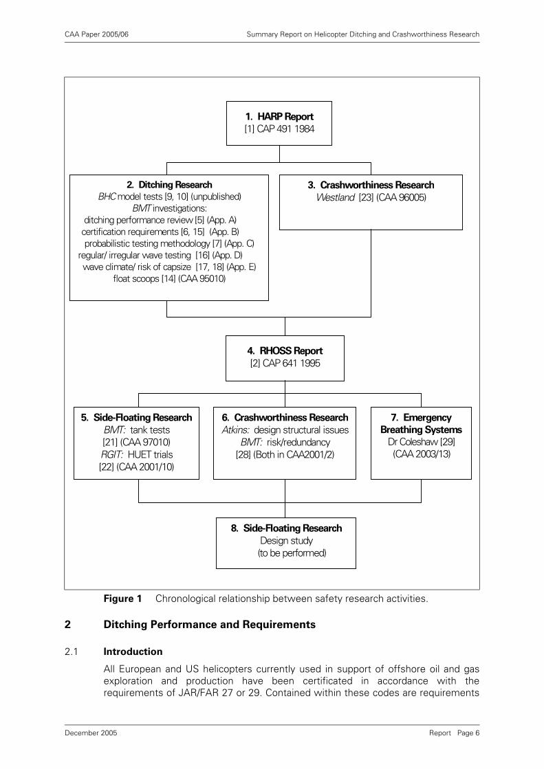
The CAA's on-going research activities in helicopter ditching and water impactfollowed directly from the recommendations of the HARP and RHOSS Reports, andform the basis for the present report. Figure 1 illustrates the chronological relationshipbetween these research activities and the HARP (box 1) and RHOSS (box 4) reports,and refers to CAA papers in which results from this research are presented, togetherwith a number of hitherto unpublished papers and reports, which are included asAppendices to this report.
The research detailed in Figure 1 is covered in the report as follows:
• Box 2 – Sections 2 and 3.2 (float scoops).
• Box 3 – Section 4.
• Box 5 – Section 3.3
• Box 6 – Section 4.
• Box 7 – Section 5.
• Box 8 – Section 6.2.
All of the CAA's ditching and water impact research has been presented to, andreviewed by, two international regulatory bodies: the JAA HOSS and the FAA/JAAWIDDCWG. These activities are covered in Section 6.1.
Overall top-level conclusions of all the research performed are presented in Section 7of this report, and lists of abbreviations and references are given in Sections 8 and 9respectively.
Report Page 5December 2005
CAA Paper 2005/06 Summary Report on Helicopter Ditching and Crashworthiness Research
2 Ditching Performance and Requirements
2.1 Introduction
All European and US helicopters currently used in support of offshore oil and gasexploration and production have been certificated in accordance with therequirements of JAR/FAR 27 or 29. Contained within these codes are requirements
Figure 1 Chronological relationship between safety research activities.
1. HARP Report
[1] CAP 491 1984
2. Ditching Research
BHC model tests [9, 10] (unpublished) BMT investigations:
ditching performance review [5] (App. A) certification requirements [6, 15] (App. B)probabilistic testing methodology [7] (App. C)
regular/ irregular wave testing [16] (App. D)wave climate/ risk of capsize [17, 18] (App. E)
float scoops [14] (CAA 95010)
3. Crashworthiness Research
Westland [23] (CAA 96005)
4. RHOSS Report
[2] CAP 641 1995
7. Emergency
Breathing Systems
Dr Coleshaw [29](CAA 2003/13)
5. Side-Floating Research
BMT: tank tests [21] (CAA 97010) RGIT: HUET trials [22] (CAA 2001/10)
6. Crashworthiness Research
Atkins: design structural issuesBMT: risk/redundancy
[28] (Both in CAA2001/2)
8. Side-Floating Research
Design study (to be performed)
Report Page 6December 2005
CAA Paper 2005/06 Summary Report on Helicopter Ditching and Crashworthiness Research
27/29.801 pertaining to 'ditching', which is defined to be an emergency landing onwater, deliberately executed, with the intent of abandoning the helicopter as soon aspractical. The helicopter is assumed to be intact prior to water entry, with all controlsand essential systems, except engines, functioning properly.
Whilst compliance with requirement 27 or 29.801 is optional for the manufacturer,operational rules prescribe a number of requirements applicable when the helicopteris being operated over water. These rules specify equipment intended to enhanceoccupant survivability in the event of a forced landing on the surface of the water.Those helicopters being operated under FAR Part 135 are required to be equippedwith floats when operating over water. Those helicopters operating under JAR OPS3 are required to be similarly equipped, except those operating in Performance Class1 (Category A engine failure accountability), which are permitted to operate up to 10minutes flying time from land without floats. Such equipment is intended to keep thehelicopter upright on the surface long enough for the occupants to escape. The FARand JAR also require life-rafts, life-jackets and survival equipment to be carried inorder to enhance survivability until rescue arrives.
2.2 Helicopter Ditching Review
In 1992 the CAA commissioned BMT to review a number of documents relating tohelicopter ditching, including the then-current UK Emergency Alighting on Waterhelicopter design requirements specified in British Civil Airworthiness Requirements(BCAR) Paper no. G779, dated 7 October 1985. The objectives of these reviewstudies, reported in [5, 6, 7], were:
• To carry out a critical review of certain documents relating to ditching performanceand requirements, to draw conclusions and prepare an overview documentsuitable for publication by the CAA.
• To perform a critical review of BCAR Paper no. G779 relating to helicopter ditching,to recommend how the BCAR requirements might be improved and whether therewere better ways to assess a helicopter's water-borne stability.
• To review helicopter ditching performance over the previous 20 years, and toassess the practicality of imposing a new probability-based methodology for NorthSea helicopter operations.
2.2.1 Helicopter Ditching Performance Review (1993)
The first of these BMT reports [5] was prepared in 1993 to meet the first of the aboveobjectives, and is reproduced in Appendix A.
An earlier internal CAA report [8] had stated that the objective of ditching certificationis to ensure that the helicopter remains upright for sufficient time for the occupantsto escape (5 minutes). This means that there should be an acceptably low probabilityof meeting a wave that is large enough or steep enough to capsize the helicopter inthis short time interval. BMT's report [5] noted that the probability of experiencing acapsize depends on two key factors:
• The height and period (or slope) of the wave required to capsize the helicopter.
• The probability of experiencing such a wave, or larger, during the exposure period.
The report went on to review the current understanding of these two factors asevidenced by five reports [8, 9, 10, 11, 12], then drew attention to gaps in currentunderstanding and made recommendations about the direction of future research.The report concluded that there were more important gaps in current understandingof the first factor than of the second.
Report Page 7December 2005
CAA Paper 2005/06 Summary Report on Helicopter Ditching and Crashworthiness Research
Results from model tests performed by the British Hovercraft Corporation (BHC) ona range of different helicopter types were examined. These tests had been performedin both regular and irregular waves. The results showed that the helicopter typestested generally had little difficulty in complying with the (then-current) BCAR regularwave steepness criterion, but all had capsized in irregular waves less severe than theimplied BCAR sea state 6 limit.
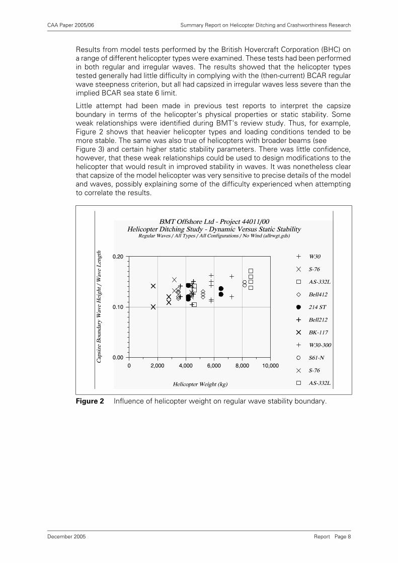
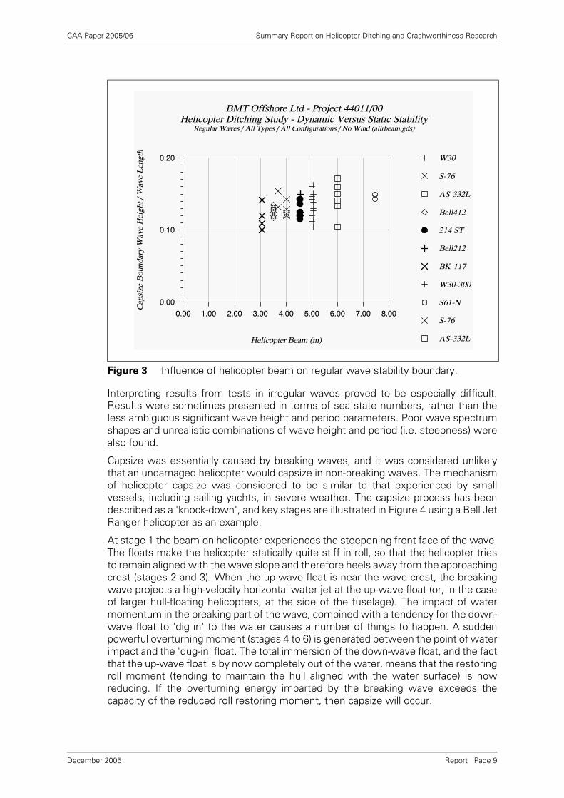
Little attempt had been made in previous test reports to interpret the capsizeboundary in terms of the helicopter's physical properties or static stability. Someweak relationships were identified during BMT's review study. Thus, for example,Figure 2 shows that heavier helicopter types and loading conditions tended to bemore stable. The same was also true of helicopters with broader beams (see Figure 3) and certain higher static stability parameters. There was little confidence,however, that these weak relationships could be used to design modifications to thehelicopter that would result in improved stability in waves. It was nonetheless clearthat capsize of the model helicopter was very sensitive to precise details of the modeland waves, possibly explaining some of the difficulty experienced when attemptingto correlate the results.
Figure 2 Influence of helicopter weight on regular wave stability boundary.
Report Page 8December 2005
CAA Paper 2005/06 Summary Report on Helicopter Ditching and Crashworthiness Research
Interpreting results from tests in irregular waves proved to be especially difficult.Results were sometimes presented in terms of sea state numbers, rather than theless ambiguous significant wave height and period parameters. Poor wave spectrumshapes and unrealistic combinations of wave height and period (i.e. steepness) werealso found.
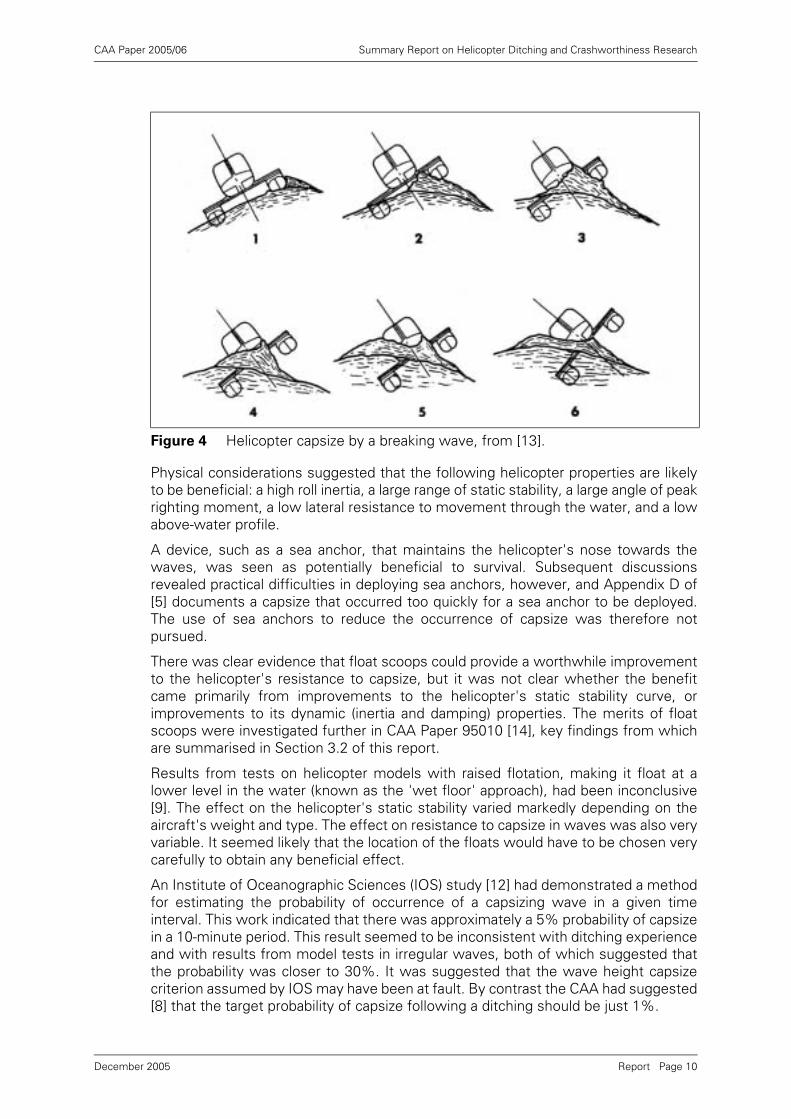
Capsize was essentially caused by breaking waves, and it was considered unlikelythat an undamaged helicopter would capsize in non-breaking waves. The mechanismof helicopter capsize was considered to be similar to that experienced by smallvessels, including sailing yachts, in severe weather. The capsize process has beendescribed as a 'knock-down', and key stages are illustrated in Figure 4 using a Bell JetRanger helicopter as an example.
At stage 1 the beam-on helicopter experiences the steepening front face of the wave.The floats make the helicopter statically quite stiff in roll, so that the helicopter triesto remain aligned with the wave slope and therefore heels away from the approachingcrest (stages 2 and 3). When the up-wave float is near the wave crest, the breakingwave projects a high-velocity horizontal water jet at the up-wave float (or, in the caseof larger hull-floating helicopters, at the side of the fuselage). The impact of watermomentum in the breaking part of the wave, combined with a tendency for the down-wave float to 'dig in' to the water causes a number of things to happen. A suddenpowerful overturning moment (stages 4 to 6) is generated between the point of waterimpact and the 'dug-in' float. The total immersion of the down-wave float, and the factthat the up-wave float is by now completely out of the water, means that the restoringroll moment (tending to maintain the hull aligned with the water surface) is nowreducing. If the overturning energy imparted by the breaking wave exceeds thecapacity of the reduced roll restoring moment, then capsize will occur.
Figure 3 Influence of helicopter beam on regular wave stability boundary.
Report Page 9December 2005
CAA Paper 2005/06 Summary Report on Helicopter Ditching and Crashworthiness Research
Physical considerations suggested that the following helicopter properties are likelyto be beneficial: a high roll inertia, a large range of static stability, a large angle of peakrighting moment, a low lateral resistance to movement through the water, and a lowabove-water profile.
A device, such as a sea anchor, that maintains the helicopter's nose towards thewaves, was seen as potentially beneficial to survival. Subsequent discussionsrevealed practical difficulties in deploying sea anchors, however, and Appendix D of[5] documents a capsize that occurred too quickly for a sea anchor to be deployed.The use of sea anchors to reduce the occurrence of capsize was therefore notpursued.
There was clear evidence that float scoops could provide a worthwhile improvementto the helicopter's resistance to capsize, but it was not clear whether the benefitcame primarily from improvements to the helicopter's static stability curve, orimprovements to its dynamic (inertia and damping) properties. The merits of floatscoops were investigated further in CAA Paper 95010 [14], key findings from whichare summarised in Section 3.2 of this report.
Results from tests on helicopter models with raised flotation, making it float at alower level in the water (known as the 'wet floor' approach), had been inconclusive[9]. The effect on the helicopter's static stability varied markedly depending on theaircraft's weight and type. The effect on resistance to capsize in waves was also veryvariable. It seemed likely that the location of the floats would have to be chosen verycarefully to obtain any beneficial effect.
An Institute of Oceanographic Sciences (IOS) study [12] had demonstrated a methodfor estimating the probability of occurrence of a capsizing wave in a given timeinterval. This work indicated that there was approximately a 5% probability of capsizein a 10-minute period. This result seemed to be inconsistent with ditching experienceand with results from model tests in irregular waves, both of which suggested thatthe probability was closer to 30%. It was suggested that the wave height capsizecriterion assumed by IOS may have been at fault. By contrast the CAA had suggested[8] that the target probability of capsize following a ditching should be just 1%.
Figure 4 Helicopter capsize by a breaking wave, from [13].
Report Page 10December 2005
CAA Paper 2005/06 Summary Report on Helicopter Ditching and Crashworthiness Research
It was noted that the attachment of floats to the engine cowlings could preventpermanent total inversion of the helicopter, and permit it to float in a stable side-floating attitude following capsize. The concept of using additional flotation units toprevent total inversion was investigated in a subsequent study, described in CAAPaper 97010 [21] (see Section 3.3).
The report made a number of specific recommendations, many of which werefollowed up in subsequent CAA work. These recommendations included:
• Future model tests on helicopters in waves should concentrate on behaviour inlong sequences of irregular waves, so that the probability of capsize can beproperly estimated.
• Means should be sought to reduce the risk of capsize which, ditching evidence andmodel tests suggest, is considerably higher than the CAA target.
• Computer simulation models should be developed further to represent floatinghelicopters subjected to regular, irregular and breaking waves, and access toexisting model test data should be sought in order to validate theoreticalpredictions.
• The float scoop concept appeared to provide significant benefit, and should bedeveloped further.
• Lowering the level of the helicopter in the water (the 'wet floor' concept) requiredfurther detailed investigation before determining whether (and how) floats shouldbe raised on any individual helicopter type.
• Attention should be given to measures (such as engine cowling mounted floats)that would prevent permanent inversion following capsize.
• Consideration should be given to extending the IOS probabilistic analysis, andcapsize probability analyses should be performed using long-term, good-qualityNorth Sea data sets.
2.2.2 Helicopter Ditching Requirements Review (1993-1995)
Report [6] reviewed the UK Emergency Alighting on Water helicopter designrequirements specified in British Civil Airworthiness Requirements (BCAR) Paper no.G779, dated 7 October 1985. The main objectives of this study were to recommendhow the requirements might be improved, and whether there were better ways toassess a helicopter's water-borne stability. This report was prepared in 1993 at a timewhen all helicopters operating in the UK North Sea were certificated according toBCAR. This report is reproduced in Appendix B1.
The BCAR requirements were superseded by JAR/FAR airworthiness requirements27 and 29, and BMT undertook a further review [15] in 1995 of the differencesbetween the BCAR and JAR requirements for ditching certification. This report isreproduced in Appendix B2. Both review studies reached similar conclusions, and aretherefore discussed together.
Both the BCAR and JAR requirements contained ambiguities in terms of theperformance expected in regular and irregular wave model tests. These requirementsappeared to have been interpreted in the past to mean that the helicopter may complywith one or other criterion, but not necessarily with both. Both sets of requirementsalso contained ambiguities in their definitions of wave steepness.
All of the existing helicopter types considered in the earlier BMT review [5] seemedto comply with the regular wave steepness criterion, but none seemed to complywith the BCAR implied irregular wave, sea state 6 criterion. Many capsized in seastate 4, and the remainder in sea state 5. It was deduced that the regular wave
Report Page 11December 2005
CAA Paper 2005/06 Summary Report on Helicopter Ditching and Crashworthiness Research
steepness criterion was being applied in isolation, and that results from any irregularwave tests were being ignored.
It was noted, however, that JAR requirements referred to 'reasonably probable waterconditions', which seemed to be interpreted as 'not less than sea state 4'. The BCARrequirement therefore seemed to be more onerous, and invited the possibility thatmore severe conditions than sea state 6 should be considered in particulargeographical areas. These ambiguities were considered to be undesirable, andclarification of the requirements was recommended.
Results from helicopter model capsize tests in regular waves were considered likelyto be misleading, and should be discouraged. An undamaged helicopter will normallyonly capsize in breaking waves. The steepness at which regular waves break in awave test basin depends primarily on the purity of the wavemaker motion, thedistance travelled by the waves, and the presence of spurious waves in the basin.Results from model tests in breaking 'regular' waves are therefore likely to dependmore on the wave basin's properties than on characteristics of the helicopter. Anirregular wave criterion was considered to offer a more realistic measure of the likelyactual performance of a helicopter ditched in the sea.
The first report [6] also discussed the merits of defining a maximum probability ofcapsize in a given operational area as an alternative to defining capsize performancein specified sea states. This possibility was investigated in a follow-up CAA study [7](see Section 2.2.3). Various deficiencies and differences between the BCAR and JARrequirements were also noted in [15].
The two review reports [6, 15] recommended that:
• Current practice, of defining wave conditions using sea state numbers, should bedropped in favour of a more precise definition in terms of significant wave height,wave period and spectrum shape.
• The designer should be required to select a sea state with an appropriately lowprobability of exceedance in the intended area of operation.
• Sea state steepness 1 should be more rigorously defined, possibly linking thisrequirement to one based on actual wave conditions in the area of operation usingprobabilities of exceedance.
• The criteria should focus on irregular wave model testing, defined in terms ofsignificant wave height, wave period and spectrum shape, together with adefinition of the way in which the severity of test conditions should be selected,and a minimum standard for model testing.
• Use of regular wave model tests, based on a specific wave steepness criterion,should be discouraged because capsize normally occurs only in breaking waves,and the results from regular wave tests are likely to depend primarily on the wavebasin's properties rather than those of the helicopter.
• If damage to the flotation system is considered to be a reasonably probableoccurrence, it will be necessary to define sea state requirements for evaluatinghelicopter stability with damaged flotation. There are various possible ways inwhich to do this. The sea states used to evaluate damaged flotation might be thesame as are used when the flotation is intact, or the same as when the hull andairframe are damaged.
1. The steepness of an irregular sea state is often defined in terms of its significant steepness, ,
where g is the acceleration due to gravity, Hs is the significant wave height and Tz is the mean zero up-crossing wave period.
2/2 zss gTHS π=
Report Page 12December 2005
CAA Paper 2005/06 Summary Report on Helicopter Ditching and Crashworthiness Research
2.2.3 Ditching Performance and Probabilistic Methodology (1993)
Report [7] was prepared in 1993 as a result of the recommendations of [6]. Itsummarised the findings from the two earlier BMT reports [5, 6], and assessed thepracticality of imposing a new probability-based methodology for helicopter ditchingcertification. This report is reproduced in Appendix C of this report.
Report [7] considered that the CAA helicopter certification requirements (BCAR)relating to ditching were ambiguous and deficient in certain respects, most notably inthe way in which limiting wave conditions were defined. It proposed that therequirements could be improved by requiring capsize performance to be demonstratedin irregular waves rather than regular waves. Irregular wave tests, whilst presentingsome significant model testing difficulties, offer a more realistic approach than usingregular waves which can potentially produce misleading results. The report alsorecommended that consideration should be given to the development of a modeltesting standard.
A simple analysis of civil and military helicopter ditching occurrences had indicatedthat the risk to the individual offshore worker of suffering a fatality due to helicoptercapsize following a controlled ditching was probably less than 3×10⁻⁵ per year (orabout once every 30,000 man years). However, the report recommended that meansshould be sought to reduce the risk of capsize following ditching because this riskseemed to be significantly higher than the CAA's stated target of 1% [8].
The report suggested a move away from a prescriptive wave condition requirement.'Risk of capsize' targets might be defined instead. The designer would be required todemonstrate that these targets are achieved by the helicopter within a defined areaof operation. Existing probabilistic work on capsize should be extended to cope withvarying probabilities of capsize with wave height, and then used in conjunction withlong-term North Sea wave data sets to derive probabilities of capsize.
2.3 Regular and Irregular Wave Testing (1996)
Earlier reviews [6, 15] had noted ambiguities in the then-current BCAR and JARcertification requirements for model tests to assess helicopter stability after ditching,especially in the performance expected in regular and irregular waves. None of theexisting helicopters considered in the earlier reviews seemed to have passed theBCAR irregular sea state criterion, but all seemed to have passed the regular wavesteepness criterion. It was also noted that the JAR irregular sea state criterion wasless stringent (sea state 4) than the BCAR criterion (sea state 6).
BMT subsequently [16] compared the costs of performing two alternative series ofmodel tests. One test programme was considered to be typical of that required tocertificate a helicopter according to existing regular wave requirements, and thesecond to meet modified irregular wave requirements. This report is reproduced inAppendix D.
Two scopes of work were presented and costs were summarised. The advantagesand disadvantages of each approach were discussed, together with data analysisrequirements. Both test programmes included tests to define and demonstrate staticstability characteristics.
The conventional test programme included a number of irregular wave tests as wellas a systematic series of regular wave tests. This test programme was regarded astypical of those currently performed for certification. The irregular wave testprogramme consisted entirely of irregular wave tests (no role was seen for regularwave tests), and was based on demonstrating an 80% probability of remainingupright in sea state 4. The model would be tested in four conditions: fully and lightlyloaded, with the centre of gravity well forward and aft.
Report Page 13December 2005
CAA Paper 2005/06 Summary Report on Helicopter Ditching and Crashworthiness Research
Similar costs were found in both cases, although it was noted that costs woulddepend on the particular capabilities of, and procedures followed by, a given wavetest basin. Of considerable greater significance was the relative reliability andstatistical significance of the results obtained by the two methods. On these groundsthe irregular-wave procedure was considered to be far superior, providing a far morerealistic measure of the actual performance of a helicopter ditched in the sea.
2.4 Helicopter Capsize Risks in UK Sea Areas (1997)
Earlier review studies [5, 6, 7] questioned whether more stringent criteria might beappropriate in particular geographical areas where sea conditions are more severe,and the risks of capsize correspondingly higher. A further BMT study [17] thereforeinvestigated the occurrence of different sea states on six different routes in the NorthSea and West of Shetland, together with the associated helicopter capsize risks. Itwas shown that, on average in the North Sea, a helicopter making a controlled landingon the water and fitted with an emergency flotation system compliant with theguidance might expect to be capsized by waves on about 30% of occasions. A furtherreport [18] investigated sea conditions in which a helicopter had ditched, but notcapsized, near the Brae Alpha platform in January 1995. These two reports arereproduced together in Appendix E.
2.4.1 Wave Climate Study
The first of these two reports [17] noted that research studies performed for the CAAhad considered sea states in which capsize of a ditched helicopter might occur, andin the ability of helicopter emergency flotation systems to survive an impact with thesea and thus keep the damaged helicopter afloat. The risks associated with theseoccurrences would clearly depend on the severity of the sea state at the time of theincident, and the likelihood of any given sea state would depend in turn on the natureof the local wave climate. This wave climate varies considerably between differentsea areas.
Six typical helicopter routes used to serve the oil and gas industry in the southern,central and northern areas of the North Sea and West of Shetland were selected forthe wave climate study. The data was interpreted in terms of the probability ofexceeding particular sea states specified in the helicopter airworthiness certificationrequirements. As noted in review reports [6, 15], these requirements were defined interms of survival in sea states varying between 4 and 6.
The report drew attention to the large difference in capsize risk between helicopterscapable of withstanding sea states 4 and 6. Averaged over a whole year, sea state 4is exceeded for 36% of the time in the northern North Sea, and so a helicoptercertified to sea state 4 ditching requirements may be considered to haveapproximately 1 in 3 probability of capsize in this sea area. If, however, the helicopteris capable of meeting the more onerous sea state 6 ditching requirement, there wouldbe only a 2% (or 1 in 50) probability of capsize. This result dramatically demonstratesthe large difference in risk implied by different certification requirements. In this samesea area the probability of exceeding sea state 4 varied from 65% in winter to only7% in summer, again implying a large difference in risk. As expected, the risk alsovaried substantially between different sea areas, sea state 4 being exceeded for only14% of the time in the southern North Sea.
The study did not compare risks of capsize for individual helicopter types. It wasnoted, however, that the data could be used in further studies on particular helicoptertypes to assess the risk of capsize following a ditching, and to assess the severity ofwave impacts resulting from helicopter crashes onto the sea.
Report Page 14December 2005
CAA Paper 2005/06 Summary Report on Helicopter Ditching and Crashworthiness Research
2.4.2 G-TIGK Ditching
The second report [18] investigated circumstances in which a Super Puma helicopter(G-TIGK) had ditched in the North Sea near the Brae Alpha platform on 19th January1995. Sea conditions at the time of ditching were rough (sea state 5), but theemergency flotation system worked well, and the helicopter did not capsize. Thecrew and passengers were able to escape to the life-rafts without injury. Thehelicopter eventually sank a few hours later when the flotation was damaged as avessel attempted to get alongside for salvage purposes.
Information on weather conditions at the time of ditching was gathered to help setthe apparently good performance of the emergency flotation system into contextwith research work on helicopter ditching. Although detailed measurements were notavailable, data from the UK Meteorological Office's wave forecast model wereexamined, and significant wave steepness values1 were estimated over the period ofthe incident. All the available evidence indicated that wave conditions were not moresevere than sea state 5 at any time between ditching and sinking. Conditions werenonetheless deteriorating, and were nearer the top end of sea state 5 by the time thehelicopter sank.
Although small spilling breakers ('whitecaps') could be seen in a photograph taken atthe time, and the significant wave steepness increased from 1/21 to 1/17 towards theend of the period of the incident, these sea states were considered to be notparticularly steep. Breaking waves were therefore considered to be of insufficientmagnitude to cause capsize. The photograph also appeared to show the helicopterheading into the wind and waves. If this was true throughout, then this would alsohave been a major factor reducing the likelihood of capsize.
3 Helicopter Ditching and Capsize Research
3.1 Introduction
Emergency flotation systems (EFS) have been mandated on UK offshore helicopterssince the 1970s for extended flights over water. It is difficult if not impossible,however, to design practical flotation systems that will keep a helicopter afloat andstable in the more severe sea conditions prevalent in the northern North Sea duringwinter months.
The CAA initiated a major programme of research into helicopter ditching and capsizein response to the HARP Report's [1] recommendation that the stability problems ofditched helicopters should be urgently pursued, and the RHOSS Report [2] stronglysupported the CAA's then on-going research into helicopter crashworthiness,flotation and stability.
Sections 3.2 and 3.3 review the history of this research programme, and summarisethe main phases of the work and key findings. Section 3.3.6 concludes with an outlineof work yet to be performed.
3.1.1 The Wet Floor Approach
Model tests conducted by the British Hovercraft Corporation (BHC) in the mid 1980sinvestigated two possible ways to improve a helicopter's static stability and capsizeperformance. One of these involved raising the floats.
1. The significant steepness of an irregular sea state is, where g is the acceleration due to gravity,
Hs is the significant wave height and Tz is the mean zero up-crossing wave period.
2/2 zss gTHS π=
Report Page 15December 2005
CAA Paper 2005/06 Summary Report on Helicopter Ditching and Crashworthiness Research
Raising the floats makes the helicopter sit at a lower level in the water [9], and usuallyleads to flooding of the passenger cabin. This is known as the 'wet floor' approach,and contrasts with the 'dry floor' approach which was mandated under then-currentBCAR ditching requirements. BCAR stated that the sill of any exit used for emergencyevacuation should be above the calm water flotation line of the helicopter whenfloating on water following an emergency landing.
Results from the BHC 'wet floor' model tests were inconclusive [5], and the effectson both the helicopter's static stability and its capsize performance in waves werevery variable, depending on the aircraft's weight, type and the test conditions. Itseemed likely that the location of the floats would have to be chosen very carefully toobtain any beneficial effect. Reference [5] summarised key findings from these tests,and recommended numerical simulation studies to obtain a better understanding ofthe way in which the helicopter's static stability properties influence the capsizeboundary.
A review of relative merits [19] concluded that there would be practical difficulties anduncertainties in adopting the 'wet floor' approach. These difficulties included theshort time necessary to attain the flooded state, how to flood the cabin in a controlledmanner, the positioning of floats to avoid blocking doors and escape hatches,difficulties with deploying life-rafts from a flooded cabin, the variable results obtainedfrom the BHC model tests, the increased risk of rotor strike (on a wave) andconsequent capsize, psychological factors and possibly increased risks ofhypothermia to unprotected passengers. Reference [19] concluded that the additionalrisks to unprotected personnel and the inconclusive nature of the test resultsprecluded the adoption of the 'wet floor' approach in preference to the 'dry floor'approach for conventional airline-type operations. The report nonetheless concludedthat the advantage of improved stability in severe conditions might justify use of the'wet floor' approach in operations over severe sea areas where personnel wearprotective clothing and are trained in escape procedures from a flooded helicopter.
In view of the concerns expressed in reference [19] and the inconclusive nature ofresults from the BHC model tests, the 'wet floor' approach was not pursued.
3.2 Float Scoops (1995)
The second way of improving helicopter stability investigated by BHC was that ofadding water scoops to the emergency flotation. These scoops would be similar tothose routinely used on inflatable life-rafts to improve stability. Model tests at BHC[10] showed that float scoops provided significant and generally consistent benefits,increasing the helicopter's capsize threshold by about one sea state for all but one ofthe nine helicopter types tested.
The CAA therefore commissioned BMT to undertake a follow-up study [14], with theassistance of Westland Helicopters Limited, to consolidate the state-of-art as regardsfloat scoops and, specifically, to estimate the cost implications of fitting scoops to atypical large transport helicopter.
An outline design for float scoops was conducted for the Agusta/ Westland EH101civil transport helicopter. The increased float forces resulting from the addition of floatscoops were estimated, and these loads compared with design calculations for theoriginal helicopter in order to establish the structural and cost implications for thehelicopter, floats and float fixings.
Estimates of the dynamic forces experienced by the floats, with and without scoops,indicated that the magnitude of these forces depends crucially on the zero-crossingperiod of the sea state selected for analysis and, depending on the selection of thisperiod, might lead to forces larger or smaller than the simple static load assumptions
Report Page 16December 2005
CAA Paper 2005/06 Summary Report on Helicopter Ditching and Crashworthiness Research
currently used in the helicopter design process. In the cases studied, the addition ofthe scoops to the floats increased the forces by between 12% and 17%.
Making the conservative assumption that the increase in force would be between25% and 50%, it was estimated that the cost of the helicopter airframe mightincrease by about 1%, and the cost of the flotation bags themselves by 10%. Thiswould be expected to increase the total cost of the helicopter by about 0.28%. Thesmall weight penalty associated with the float scoops was estimated to lead to apossible reduction in payload revenue of about 0.25%.
The capsize boundaries for helicopter types currently operating in the North Searegion lie in the sea state range 4 to 5. Fitting float scoops to existing helicopter typeswould raise their capsize boundaries by approximately one sea state, significantlyreducing the risk of capsize following a ditching (see Section 2.4.1). The final reporton this study was published in CAA Paper 95010 [14].
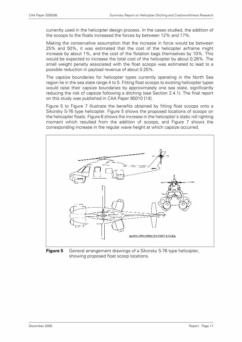
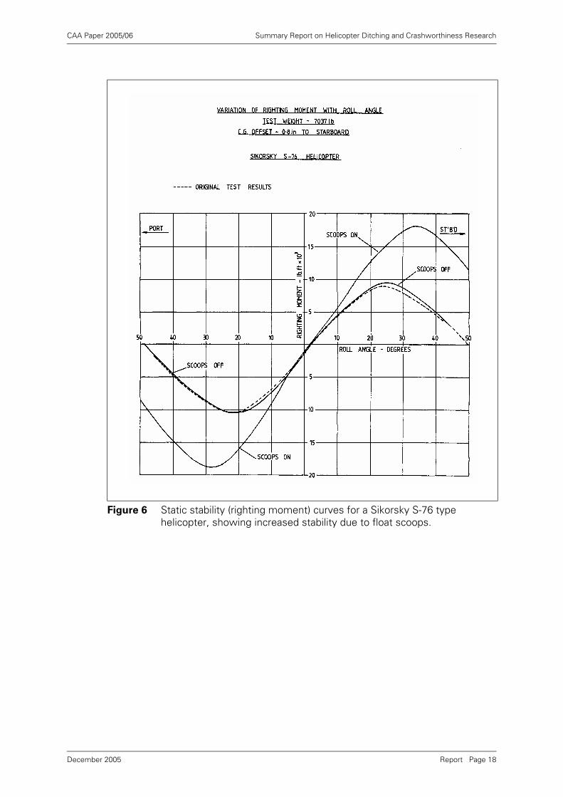
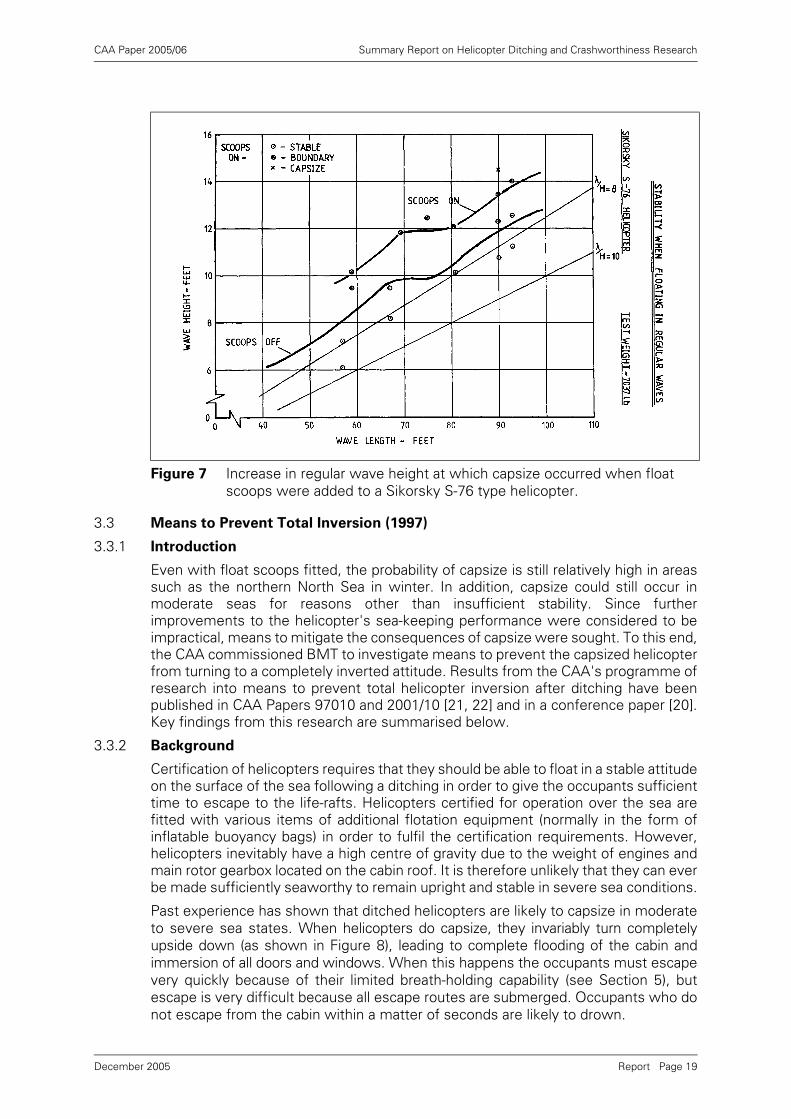
Figure 5 to Figure 7 illustrate the benefits obtained by fitting float scoops onto aSikorsky S-76 type helicopter. Figure 5 shows the proposed locations of scoops onthe helicopter floats. Figure 6 shows the increase in the helicopter's static roll rightingmoment which resulted from the addition of scoops, and Figure 7 shows thecorresponding increase in the regular wave height at which capsize occurred.
Figure 5 General arrangement drawings of a Sikorsky S-76 type helicopter, showing proposed float scoop locations.
Report Page 17December 2005
CAA Paper 2005/06 Summary Report on Helicopter Ditching and Crashworthiness Research
Figure 6 Static stability (righting moment) curves for a Sikorsky S-76 type helicopter, showing increased stability due to float scoops.
Report Page 18December 2005
CAA Paper 2005/06 Summary Report on Helicopter Ditching and Crashworthiness Research
3.3 Means to Prevent Total Inversion (1997)
3.3.1 Introduction
Even with float scoops fitted, the probability of capsize is still relatively high in areassuch as the northern North Sea in winter. In addition, capsize could still occur inmoderate seas for reasons other than insufficient stability. Since furtherimprovements to the helicopter's sea-keeping performance were considered to beimpractical, means to mitigate the consequences of capsize were sought. To this end,the CAA commissioned BMT to investigate means to prevent the capsized helicopterfrom turning to a completely inverted attitude. Results from the CAA's programme ofresearch into means to prevent total helicopter inversion after ditching have beenpublished in CAA Papers 97010 and 2001/10 [21, 22] and in a conference paper [20].Key findings from this research are summarised below.
3.3.2 Background
Certification of helicopters requires that they should be able to float in a stable attitudeon the surface of the sea following a ditching in order to give the occupants sufficienttime to escape to the life-rafts. Helicopters certified for operation over the sea arefitted with various items of additional flotation equipment (normally in the form ofinflatable buoyancy bags) in order to fulfil the certification requirements. However,helicopters inevitably have a high centre of gravity due to the weight of engines andmain rotor gearbox located on the cabin roof. It is therefore unlikely that they can everbe made sufficiently seaworthy to remain upright and stable in severe sea conditions.
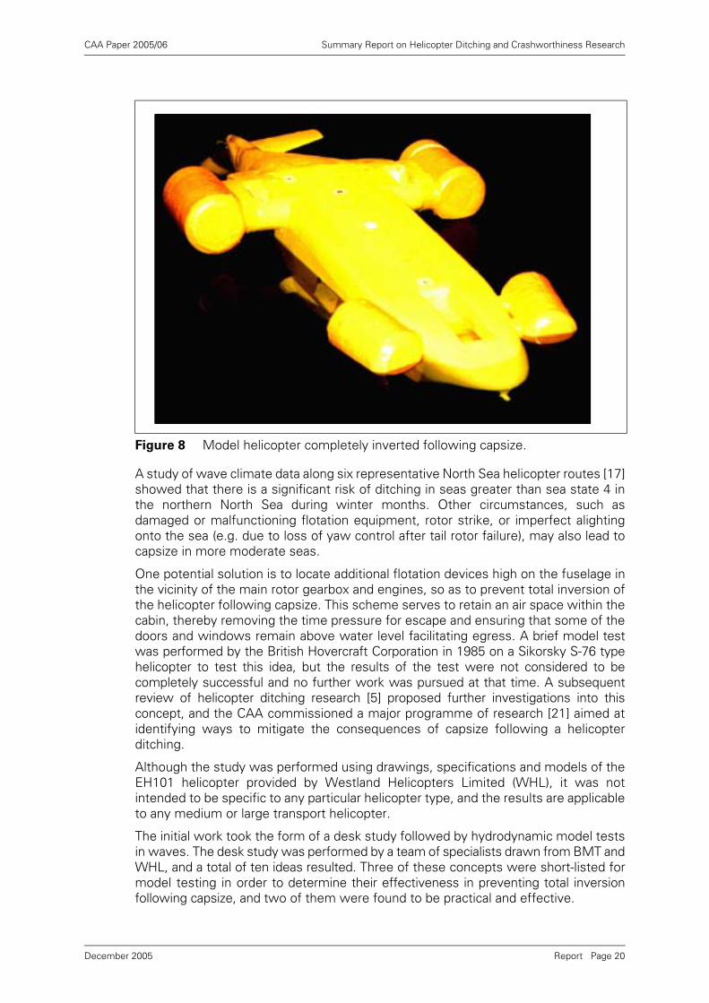
Past experience has shown that ditched helicopters are likely to capsize in moderateto severe sea states. When helicopters do capsize, they invariably turn completelyupside down (as shown in Figure 8), leading to complete flooding of the cabin andimmersion of all doors and windows. When this happens the occupants must escapevery quickly because of their limited breath-holding capability (see Section 5), butescape is very difficult because all escape routes are submerged. Occupants who donot escape from the cabin within a matter of seconds are likely to drown.
Figure 7 Increase in regular wave height at which capsize occurred when float scoops were added to a Sikorsky S-76 type helicopter.
Report Page 19December 2005
CAA Paper 2005/06 Summary Report on Helicopter Ditching and Crashworthiness Research
A study of wave climate data along six representative North Sea helicopter routes [17]showed that there is a significant risk of ditching in seas greater than sea state 4 inthe northern North Sea during winter months. Other circumstances, such asdamaged or malfunctioning flotation equipment, rotor strike, or imperfect alightingonto the sea (e.g. due to loss of yaw control after tail rotor failure), may also lead tocapsize in more moderate seas.
One potential solution is to locate additional flotation devices high on the fuselage inthe vicinity of the main rotor gearbox and engines, so as to prevent total inversion ofthe helicopter following capsize. This scheme serves to retain an air space within thecabin, thereby removing the time pressure for escape and ensuring that some of thedoors and windows remain above water level facilitating egress. A brief model testwas performed by the British Hovercraft Corporation in 1985 on a Sikorsky S-76 typehelicopter to test this idea, but the results of the test were not considered to becompletely successful and no further work was pursued at that time. A subsequentreview of helicopter ditching research [5] proposed further investigations into thisconcept, and the CAA commissioned a major programme of research [21] aimed atidentifying ways to mitigate the consequences of capsize following a helicopterditching.
Although the study was performed using drawings, specifications and models of theEH101 helicopter provided by Westland Helicopters Limited (WHL), it was notintended to be specific to any particular helicopter type, and the results are applicableto any medium or large transport helicopter.
The initial work took the form of a desk study followed by hydrodynamic model testsin waves. The desk study was performed by a team of specialists drawn from BMT andWHL, and a total of ten ideas resulted. Three of these concepts were short-listed formodel testing in order to determine their effectiveness in preventing total inversionfollowing capsize, and two of them were found to be practical and effective.
Figure 8 Model helicopter completely inverted following capsize.
Report Page 20December 2005
CAA Paper 2005/06 Summary Report on Helicopter Ditching and Crashworthiness Research
3.3.3 Devices Initially Considered
Discussions between helicopter design and hydrodynamic and stability specialistsfrom WHL and BMT took place during the first phase of the work, and ten possiblenovel flotation devices were identified:
(1) Buoyant foam-filled engine cowling panels.
(2) Engine cowling panels with integral inflatable buoyancy bags.
(3) Buoyancy bags inside the rear fuselage.
(4) Buoyancy inside the passenger cabin roof.
(5) External cabin wall floats.
(6) A flotation collar under the rotor head.
(7) Flotation attached to the top of the rotor head.
(8) Tethered inflatable flotation units.
(9) Increased passenger seat buoyancy.
(10) Dynamic chemical foam in engine spaces.
The specialists assessed the merits and disadvantages of each device, and rankedthem to determine which were the most attractive for further study based on thefollowing three qualities:
• Effectiveness - how effective is the device likely to be in preventing total inversionfollowing capsize?
• Practicality - how easy or difficult is it likely to be to incorporate the device into thedesign of a helicopter?
• Safety - is the device free from additional safety hazards to the operation of thehelicopter?
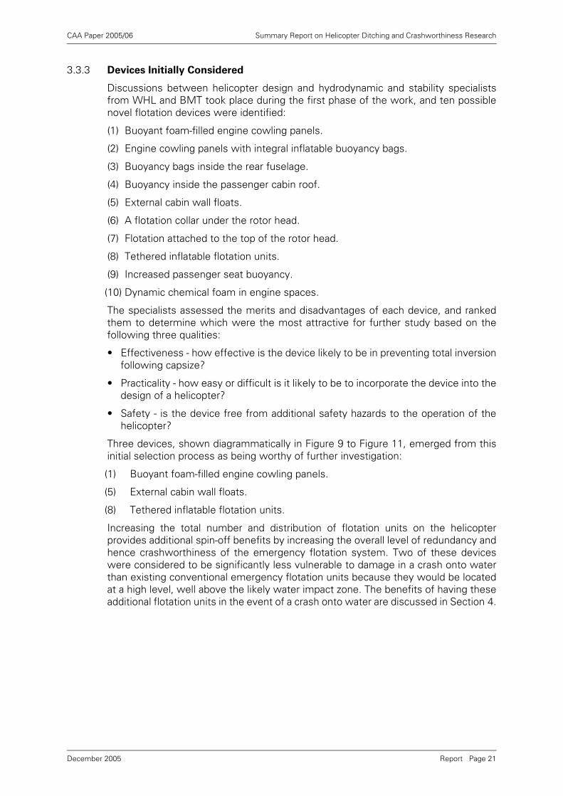
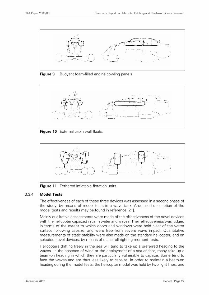
Three devices, shown diagrammatically in Figure 9 to Figure 11, emerged from thisinitial selection process as being worthy of further investigation:
(1) Buoyant foam-filled engine cowling panels.
(5) External cabin wall floats.
(8) Tethered inflatable flotation units.
Increasing the total number and distribution of flotation units on the helicopterprovides additional spin-off benefits by increasing the overall level of redundancy andhence crashworthiness of the emergency flotation system. Two of these deviceswere considered to be significantly less vulnerable to damage in a crash onto waterthan existing conventional emergency flotation units because they would be locatedat a high level, well above the likely water impact zone. The benefits of having theseadditional flotation units in the event of a crash onto water are discussed in Section 4.
Report Page 21December 2005
CAA Paper 2005/06 Summary Report on Helicopter Ditching and Crashworthiness Research
3.3.4 Model Tests
The effectiveness of each of these three devices was assessed in a second phase ofthe study, by means of model tests in a wave tank. A detailed description of themodel tests and results may be found in reference [21].
Mainly qualitative assessments were made of the effectiveness of the novel deviceswith the helicopter capsized in calm water and waves. Their effectiveness was judgedin terms of the extent to which doors and windows were held clear of the watersurface following capsize, and were free from severe wave impact. Quantitativemeasurements of static stability were also made on the standard helicopter, and onselected novel devices, by means of static roll righting moment tests.
Helicopters drifting freely in the sea will tend to take up a preferred heading to thewaves. In the absence of wind or the deployment of a sea anchor, many take up abeam-on heading in which they are particularly vulnerable to capsize. Some tend toface the waves and are thus less likely to capsize. In order to maintain a beam-onheading during the model tests, the helicopter model was held by two light lines, one
Figure 9 Buoyant foam-filled engine cowling panels.
Figure 10 External cabin wall floats.
Figure 11 Tethered inflatable flotation units.
Report Page 22December 2005
CAA Paper 2005/06 Summary Report on Helicopter Ditching and Crashworthiness Research
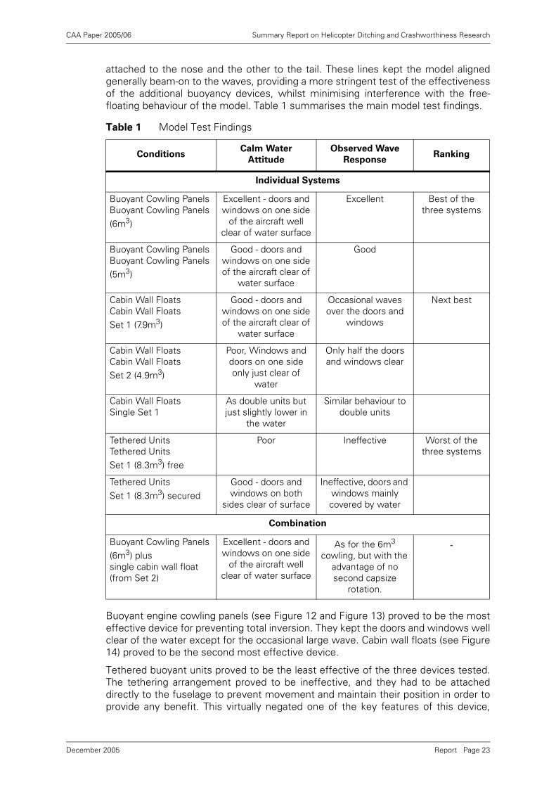
attached to the nose and the other to the tail. These lines kept the model alignedgenerally beam-on to the waves, providing a more stringent test of the effectivenessof the additional buoyancy devices, whilst minimising interference with the free-floating behaviour of the model. Table 1 summarises the main model test findings.
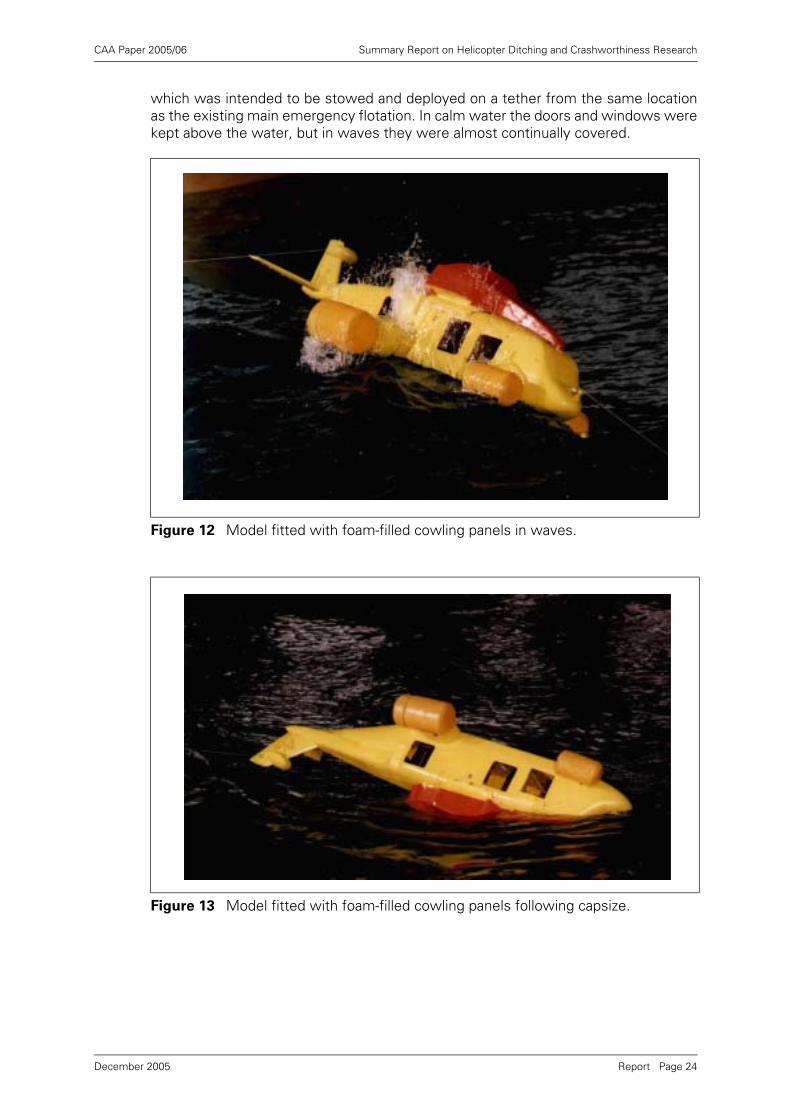
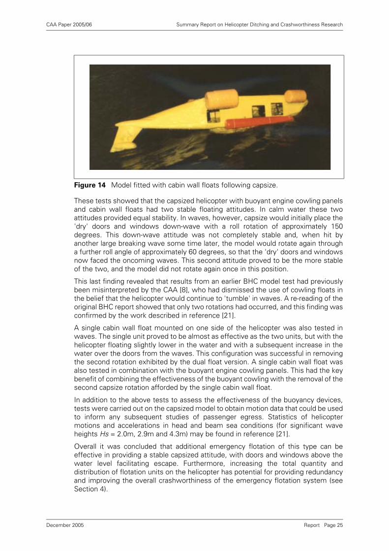
Buoyant engine cowling panels (see Figure 12 and Figure 13) proved to be the mosteffective device for preventing total inversion. They kept the doors and windows wellclear of the water except for the occasional large wave. Cabin wall floats (see Figure14) proved to be the second most effective device.
Tethered buoyant units proved to be the least effective of the three devices tested.The tethering arrangement proved to be ineffective, and they had to be attacheddirectly to the fuselage to prevent movement and maintain their position in order toprovide any benefit. This virtually negated one of the key features of this device,
Table 1 Model Test Findings
ConditionsCalm Water
Attitude
Observed Wave
ResponseRanking
Individual Systems
Buoyant Cowling PanelsBuoyant Cowling Panels(6m3)
Excellent - doors and windows on one side
of the aircraft well clear of water surface
Excellent Best of the three systems
Buoyant Cowling PanelsBuoyant Cowling Panels(5m3)
Good - doors and windows on one side of the aircraft clear of
water surface
Good
Cabin Wall FloatsCabin Wall FloatsSet 1 (7.9m3)
Good - doors and windows on one side of the aircraft clear of
water surface
Occasional waves over the doors and
windows
Next best
Cabin Wall FloatsCabin Wall FloatsSet 2 (4.9m3)
Poor, Windows and doors on one side only just clear of
water
Only half the doors and windows clear
Cabin Wall FloatsSingle Set 1
As double units but just slightly lower in
the water
Similar behaviour to double units
Tethered UnitsTethered UnitsSet 1 (8.3m3) free
Poor Ineffective Worst of the three systems
Tethered UnitsSet 1 (8.3m3) secured
Good - doors and windows on both
sides clear of surface
Ineffective, doors and windows mainly covered by water
Combination
Buoyant Cowling Panels (6m3) plussingle cabin wall float (from Set 2)
Excellent - doors and windows on one side
of the aircraft well clear of water surface
As for the 6m3 cowling, but with the
advantage of no second capsize
rotation.
-
Report Page 23December 2005
CAA Paper 2005/06 Summary Report on Helicopter Ditching and Crashworthiness Research
which was intended to be stowed and deployed on a tether from the same locationas the existing main emergency flotation. In calm water the doors and windows werekept above the water, but in waves they were almost continually covered.
Figure 12 Model fitted with foam-filled cowling panels in waves.
Figure 13 Model fitted with foam-filled cowling panels following capsize.
Report Page 24December 2005
CAA Paper 2005/06 Summary Report on Helicopter Ditching and Crashworthiness Research
These tests showed that the capsized helicopter with buoyant engine cowling panelsand cabin wall floats had two stable floating attitudes. In calm water these twoattitudes provided equal stability. In waves, however, capsize would initially place the'dry' doors and windows down-wave with a roll rotation of approximately 150degrees. This down-wave attitude was not completely stable and, when hit byanother large breaking wave some time later, the model would rotate again througha further roll angle of approximately 60 degrees, so that the 'dry' doors and windowsnow faced the oncoming waves. This second attitude proved to be the more stableof the two, and the model did not rotate again once in this position.
This last finding revealed that results from an earlier BHC model test had previouslybeen misinterpreted by the CAA [8], who had dismissed the use of cowling floats inthe belief that the helicopter would continue to 'tumble' in waves. A re-reading of theoriginal BHC report showed that only two rotations had occurred, and this finding wasconfirmed by the work described in reference [21].
A single cabin wall float mounted on one side of the helicopter was also tested inwaves. The single unit proved to be almost as effective as the two units, but with thehelicopter floating slightly lower in the water and with a subsequent increase in thewater over the doors from the waves. This configuration was successful in removingthe second rotation exhibited by the dual float version. A single cabin wall float wasalso tested in combination with the buoyant engine cowling panels. This had the keybenefit of combining the effectiveness of the buoyant cowling with the removal of thesecond capsize rotation afforded by the single cabin wall float.
In addition to the above tests to assess the effectiveness of the buoyancy devices,tests were carried out on the capsized model to obtain motion data that could be usedto inform any subsequent studies of passenger egress. Statistics of helicoptermotions and accelerations in head and beam sea conditions (for significant waveheights Hs = 2.0m, 2.9m and 4.3m) may be found in reference [21].
Overall it was concluded that additional emergency flotation of this type can beeffective in providing a stable capsized attitude, with doors and windows above thewater level facilitating escape. Furthermore, increasing the total quantity anddistribution of flotation units on the helicopter has potential for providing redundancyand improving the overall crashworthiness of the emergency flotation system (seeSection 4).
Figure 14 Model fitted with cabin wall floats following capsize.
Report Page 25December 2005
CAA Paper 2005/06 Summary Report on Helicopter Ditching and Crashworthiness Research
On the basis of these results it was concluded that foam-filled engine cowling panelsand external cabin wall floats were worthy of further development, and furtherinvestigations were recommended. In particular, an investigation of the practicalproblems posed by passenger escape from a side-floating helicopter and a helicoptertype-specific design study were recommended.
3.3.5 Human Factors Study
Following the demonstration of the practicality and effectiveness of auxiliary flotationand on the recommendation of [21], the CAA instigated a human factors study [22] atRGIT Limited to develop an appropriate technique and associated training proceduresfor egress from side-floating helicopters, and determine the overall benefits/disbenefits of the scheme by comparison with egress from a fully inverted helicopter.The study used naïve subjects who were first trained, and then evaluated duringsimulated escapes from fully inverted and side-floating cabins in RGIT's training pool.This study confirmed the expected benefits of the side-floating arrangement.
A review of accident reports and relevant research was first undertaken to identify themain issues associated with helicopter underwater escape. Particular attention waspaid to the Super Puma due to its high usage in the North Sea. An examination of anoperational Super Puma was carried out in order that the risks of egress would berealistically assessed and to ensure that the helicopter simulator closely resembledits configuration in the trials.
Practical trials were carried out using a helicopter underwater escape trainer (HUET)as a simulator. The helicopter simulator was modified so that it came to rest at anangle of 150o after capsize. Buoyancy bags were fitted above the window exits onone side to simulate the proposed flotation system.
Carefully controlled feasibility trials were performed in which all possible means ofescape from the side-floating helicopter simulator were explored. A risk assessmentwas carried out and escape procedures were developed. Thirty naïve subjects werethen recruited to evaluate escape from the side-floating helicopter simulator followingcapsize through an angle of either 150o or 210o, and to compare it with escape froma fully inverted helicopter simulator following a 180o capsize. Psychological andphysiological measurements were taken at various intervals during the trials tomeasure the subjects' performance and levels of anxiety. Subjects also rated theirperception of the difficulty associated with each escape. Each trial was filmed in orderto measure escape times and assess ease of escape. The different escapeprocedures were compared in order to assess their relative advantages anddisadvantages.
The majority of subjects preferred escape from the side-floating helicopter, and foundit to be easier. This was reflected in the fact that subjects were significantly moresatisfied with how they coped with escape in the side-floating condition (Figure 15)compared with the fully inverted condition (Figure 16). When escaping from the fullyinverted simulator, difficulties caused by disorientation, breath-holding, locating andusing the exit were more prominent than in the side-floating condition. This wasespecially true when subjects were required to make their way across the cabin toescape.
Subjects had some difficulty releasing the harness when seated on the upper side ofthe simulator in the side-floating condition. None of the problems associated withescape from a side-floating helicopter was considered to be life-threatening,however, and none outweighed the advantages of escape from a side-floatinghelicopter. On the contrary, the evidence suggested that the occupant of a side-floating helicopter would have a much better chance of escape and survival thansomeone inside a fully inverted aircraft.
Report Page 26December 2005
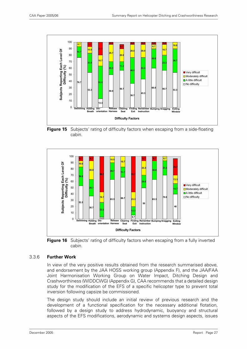
CAA Paper 2005/06 Summary Report on Helicopter Ditching and Crashworthiness Research
3.3.6 Further Work
In view of the very positive results obtained from the research summarised above,and endorsement by the JAA HOSS working group (Appendix F), and the JAA/FAAJoint Harmonisation Working Group on Water Impact, Ditching Design andCrashworthiness (WIDDCWG) (Appendix G), CAA recommends that a detailed designstudy for the modification of the EFS of a specific helicopter type to prevent totalinversion following capsize be commissioned.
The design study should include an initial review of previous research and thedevelopment of a functional specification for the necessary additional flotation,followed by a design study to address hydrodynamic, buoyancy and structuralaspects of the EFS modifications, aerodynamic and systems design aspects, issues
Figure 15 Subjects' rating of difficulty factors when escaping from a side-floating cabin.
Figure 16 Subjects' rating of difficulty factors when escaping from a fully inverted cabin.
76.7
53.3
13.3
50.056.7
36.743.3
60.056.7 53.3
16.7
30.0
50.0
20.013.3
40.033.3
30.0
23.336.7
6.7
10.0
16.7
26.720.0
20.0 20.0
6.7
16.7
10.06.7
20.0
3.3
6.7
3.3 3.3 3.3 3.3
0
10
20
30
40
50
60
70
80
90
100
Difficulty Factors
Su
bje
cts
Re
po
rtin
g E
ac
h L
ev
el
Of
Dif
fic
ult
y (
%)
Very difficult
Moderately difficult
A little difficult
No difficulty
Swimming Holding
Breath
Dis-
orientation
Release
Harness
Clearing
Seat
Finding
Exit
Remember
InstructionBumping Snagging Exiting
Window
53.3
36.7
3.3
63.3 66.7
6.7
50
63.370.0
40
30.0
26.7
23.3
26.7 16.7
13.3
20.0
30.023.3
16.7
10.0
30.0
16.7
10.016.7
23.3
23.3
6.7
13.3
6.7 6.7
56.7 56.7
6.7 6.7
26.7
0
10
20
30
40
50
60
70
80
90
100
Difficulty Factors
Su
bje
cts
Rep
ort
ing
Each
Level
Of
Dif
ficu
lty (
%)
Very difficult
Moderately difficult
A little difficult
No difficulty
Swimming Holding
Breath
Dis-
orientation
Release
HarnessClearing
Seat
Finding
Exit
Remember
Instruction
Bumping Snagging Exiting
Window
Report Page 27December 2005
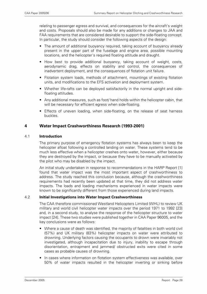
CAA Paper 2005/06 Summary Report on Helicopter Ditching and Crashworthiness Research
relating to passenger egress and survival, and consequences for the aircraft's weightand costs. Proposals should also be made for any additions or changes to JAA andFAA requirements that are considered desirable to support the side-floating concept.In particular, the study should consider the following aspects of the design:
• The amount of additional buoyancy required, taking account of buoyancy alreadypresent in the upper part of the fuselage and engine area, possible mountinglocations, and the helicopter's required floating attitude and draught.
• How best to provide additional buoyancy, taking account of weight, costs,aerodynamic drag, effects on stability and control, the consequences ofinadvertent deployment, and the consequences of flotation unit failure.
• Flotation system loads, methods of attachment, mountings of existing flotationunits, and modifications to the EFS activation and deployment system.
• Whether life-rafts can be deployed satisfactorily in the normal upright and side-floating attitudes.
• Any additional measures, such as foot/ hand holds within the helicopter cabin, thatwill be necessary for efficient egress when side-floating.
• Effects of uneven loading, when side-floating, on the release of seat harnessbuckles.
4 Water Impact Crashworthiness Research (1993-2001)
4.1 Introduction
The primary purpose of emergency flotation systems has always been to keep thehelicopter afloat following a controlled landing on water. These systems tend to bemuch less effective when a helicopter crashes onto water, however, either becausethey are destroyed by the impact, or because they have to be manually activated bythe pilot who may be disabled by the impact.
An initial study undertaken in response to recommendations in the HARP Report [1]found that water impact was the most important aspect of crashworthiness toaddress. The study reached this conclusion because, although the crashworthinessrequirements had recently been updated at that time, they did not address waterimpacts. The loads and loading mechanisms experienced in water impacts wereknown to be significantly different from those experienced during land impacts.
4.2 Initial Investigations into Water Impact Crashworthiness
The CAA therefore commissioned Westland Helicopters Limited (WHL) to review UKmilitary and world civil helicopter water impacts over the period 1971 to 1992 [23]and, in a second study, to analyse the response of the helicopter structure to waterimpact [24]. These two studies were published together in CAA Paper 96005, and thekey conclusions were as follows:
• Where a cause of death was identified, the majority of fatalities in both world civil(57%) and UK military (83%) helicopter impacts on water were attributed todrowning. Underlying factors causing the occupants to drown were invariably notinvestigated, although incapacitation due to injury, inability to escape throughdisorientation, entrapment and jammed/ obstructed exits were cited in somecases as probable causes of drowning.
• In cases where information on flotation system effectiveness was available, over50% of water impacts resulted in the helicopter inverting or sinking before
Report Page 28December 2005
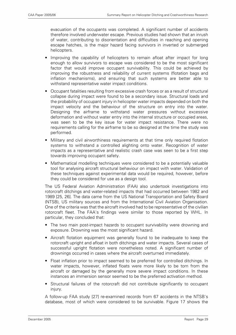
CAA Paper 2005/06 Summary Report on Helicopter Ditching and Crashworthiness Research
evacuation of the occupants was completed. A significant number of accidentstherefore involved underwater escape. Previous studies had shown that an inrushof water, contributing to disorientation and difficulties in reaching and openingescape hatches, is the major hazard facing survivors in inverted or submergedhelicopters.
• Improving the capability of helicopters to remain afloat after impact for longenough to allow survivors to escape was considered to be the most significantfactor that would improve occupant survivability. This could be achieved byimproving the robustness and reliability of current systems (flotation bags andinflation mechanisms), and ensuring that such systems are better able towithstand representative water impact conditions.
• Occupant fatalities resulting from excessive crash forces or as a result of structuralcollapse during impact were found to be a secondary issue. Structural loads andthe probability of occupant injury in helicopter water impacts depended on both theimpact velocity and the behaviour of the structure on entry into the water.Designing the airframe to withstand water pressures without excessivedeformation and without water entry into the internal structure or occupied areas,was seen to be the key issue for water impact resistance. There were norequirements calling for the airframe to be so designed at the time the study wasperformed.
• Military and civil airworthiness requirements at that time only required flotationsystems to withstand a controlled alighting onto water. Recognition of waterimpacts as a representative and realistic crash case was seen to be a first steptowards improving occupant safety.
• Mathematical modelling techniques were considered to be a potentially valuabletool for analysing aircraft structural behaviour on impact with water. Validation ofthese techniques against experimental data would be required, however, beforethey could be considered for use as a design tool.
The US Federal Aviation Administration (FAA) also undertook investigations intorotorcraft ditchings and water-related impacts that had occurred between 1982 and1989 [25, 26]. The data came from the US National Transportation and Safety Board(NTSB), US military sources and from the International Civil Aviation Organisation.One of the criteria was that the aircraft involved had to be representative of the civilianrotorcraft fleet. The FAA's findings were similar to those reported by WHL. Inparticular, they concluded that:
• The two main post-impact hazards to occupant survivability were drowning andexposure. Drowning was the most significant hazard.
• Aircraft flotation equipment was generally found to be inadequate to keep therotorcraft upright and afloat in both ditchings and water impacts. Several cases ofsuccessful upright flotation were nonetheless noted. A significant number ofdrownings occurred in cases where the aircraft overturned immediately.
• Float inflation prior to impact seemed to be preferred for controlled ditchings. Inwater impacts, however, inflated floats were more likely to be torn from theaircraft or damaged by the generally more severe impact conditions. In theseinstances an immersion sensor seemed to be the preferred activation method.
• Structural failures of the rotorcraft did not contribute significantly to occupantinjury.
A follow-up FAA study [27] re-examined records from 67 accidents in the NTSB'sdatabase, most of which were considered to be survivable. Figure 17 shows the
Report Page 29December 2005
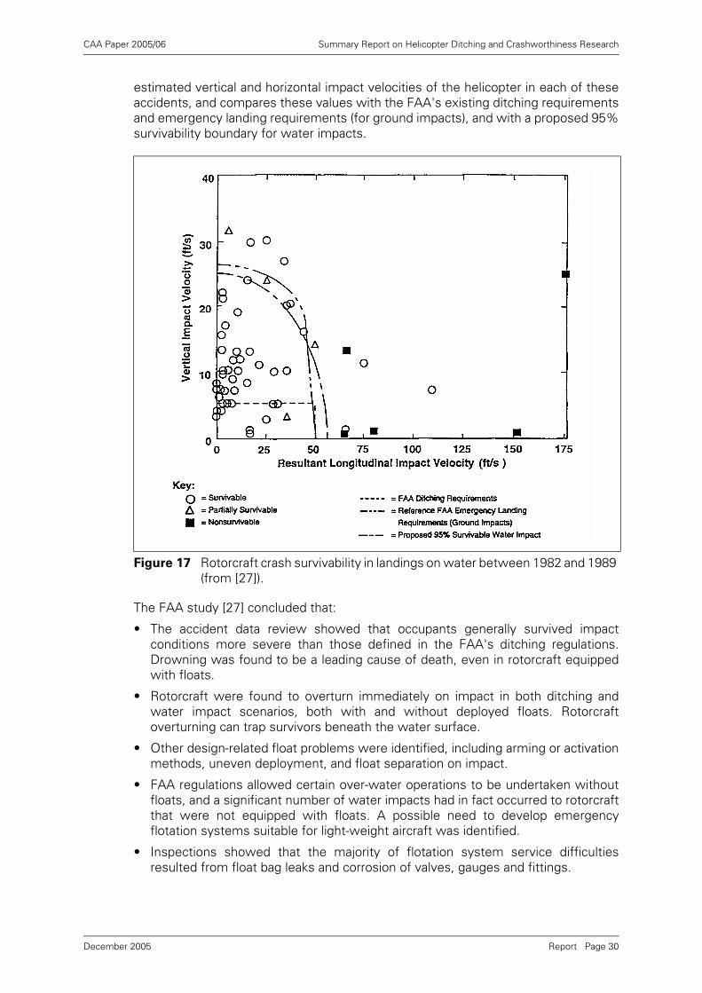
CAA Paper 2005/06 Summary Report on Helicopter Ditching and Crashworthiness Research
estimated vertical and horizontal impact velocities of the helicopter in each of theseaccidents, and compares these values with the FAA's existing ditching requirementsand emergency landing requirements (for ground impacts), and with a proposed 95%survivability boundary for water impacts.
The FAA study [27] concluded that:
• The accident data review showed that occupants generally survived impactconditions more severe than those defined in the FAA's ditching regulations.Drowning was found to be a leading cause of death, even in rotorcraft equippedwith floats.
• Rotorcraft were found to overturn immediately on impact in both ditching andwater impact scenarios, both with and without deployed floats. Rotorcraftoverturning can trap survivors beneath the water surface.
• Other design-related float problems were identified, including arming or activationmethods, uneven deployment, and float separation on impact.
• FAA regulations allowed certain over-water operations to be undertaken withoutfloats, and a significant number of water impacts had in fact occurred to rotorcraftthat were not equipped with floats. A possible need to develop emergencyflotation systems suitable for light-weight aircraft was identified.
• Inspections showed that the majority of flotation system service difficultiesresulted from float bag leaks and corrosion of valves, gauges and fittings.
Figure 17 Rotorcraft crash survivability in landings on water between 1982 and 1989 (from [27]).
Report Page 30December 2005
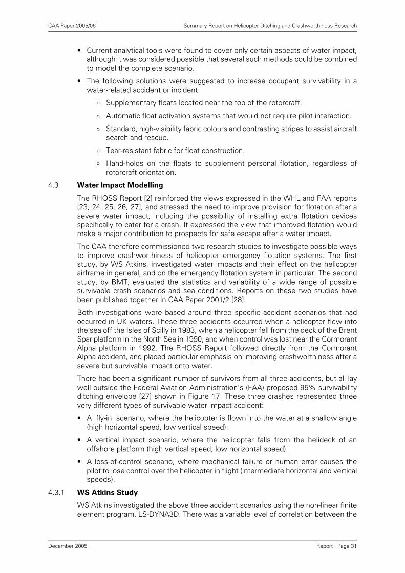
CAA Paper 2005/06 Summary Report on Helicopter Ditching and Crashworthiness Research
• Current analytical tools were found to cover only certain aspects of water impact,although it was considered possible that several such methods could be combinedto model the complete scenario.
• The following solutions were suggested to increase occupant survivability in awater-related accident or incident:
° Supplementary floats located near the top of the rotorcraft.
° Automatic float activation systems that would not require pilot interaction.
° Standard, high-visibility fabric colours and contrasting stripes to assist aircraftsearch-and-rescue.
° Tear-resistant fabric for float construction.
° Hand-holds on the floats to supplement personal flotation, regardless ofrotorcraft orientation.
4.3 Water Impact Modelling
The RHOSS Report [2] reinforced the views expressed in the WHL and FAA reports[23, 24, 25, 26, 27], and stressed the need to improve provision for flotation after asevere water impact, including the possibility of installing extra flotation devicesspecifically to cater for a crash. It expressed the view that improved flotation wouldmake a major contribution to prospects for safe escape after a water impact.
The CAA therefore commissioned two research studies to investigate possible waysto improve crashworthiness of helicopter emergency flotation systems. The firststudy, by WS Atkins, investigated water impacts and their effect on the helicopterairframe in general, and on the emergency flotation system in particular. The secondstudy, by BMT, evaluated the statistics and variability of a wide range of possiblesurvivable crash scenarios and sea conditions. Reports on these two studies havebeen published together in CAA Paper 2001/2 [28].
Both investigations were based around three specific accident scenarios that hadoccurred in UK waters. These three accidents occurred when a helicopter flew intothe sea off the Isles of Scilly in 1983, when a helicopter fell from the deck of the BrentSpar platform in the North Sea in 1990, and when control was lost near the CormorantAlpha platform in 1992. The RHOSS Report followed directly from the CormorantAlpha accident, and placed particular emphasis on improving crashworthiness after asevere but survivable impact onto water.
There had been a significant number of survivors from all three accidents, but all laywell outside the Federal Aviation Administration's (FAA) proposed 95% survivabilityditching envelope [27] shown in Figure 17. These three crashes represented threevery different types of survivable water impact accident:
• A 'fly-in' scenario, where the helicopter is flown into the water at a shallow angle(high horizontal speed, low vertical speed).
• A vertical impact scenario, where the helicopter falls from the helideck of anoffshore platform (high vertical speed, low horizontal speed).
• A loss-of-control scenario, where mechanical failure or human error causes thepilot to lose control over the helicopter in flight (intermediate horizontal and verticalspeeds).
4.3.1 WS Atkins Study
WS Atkins investigated the above three accident scenarios using the non-linear finiteelement program, LS-DYNA3D. There was a variable level of correlation between the
Report Page 31December 2005
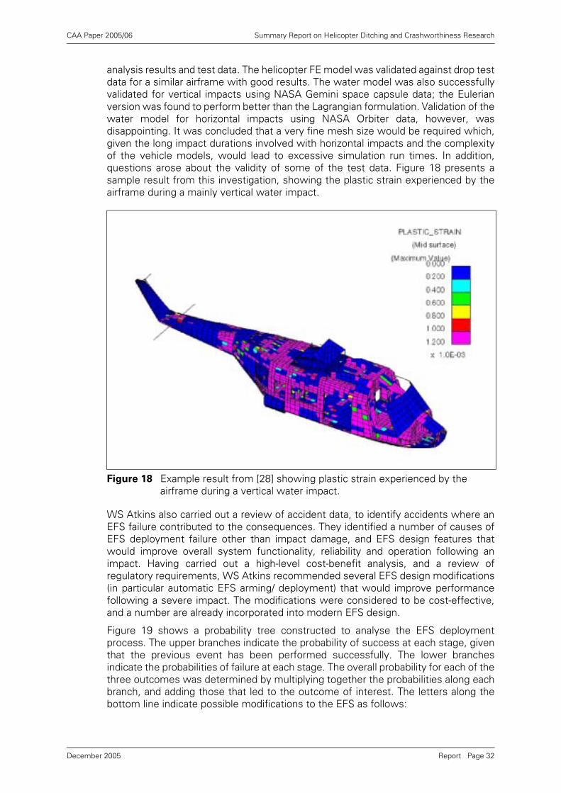
CAA Paper 2005/06 Summary Report on Helicopter Ditching and Crashworthiness Research
analysis results and test data. The helicopter FE model was validated against drop testdata for a similar airframe with good results. The water model was also successfullyvalidated for vertical impacts using NASA Gemini space capsule data; the Eulerianversion was found to perform better than the Lagrangian formulation. Validation of thewater model for horizontal impacts using NASA Orbiter data, however, wasdisappointing. It was concluded that a very fine mesh size would be required which,given the long impact durations involved with horizontal impacts and the complexityof the vehicle models, would lead to excessive simulation run times. In addition,questions arose about the validity of some of the test data. Figure 18 presents asample result from this investigation, showing the plastic strain experienced by theairframe during a mainly vertical water impact.
WS Atkins also carried out a review of accident data, to identify accidents where anEFS failure contributed to the consequences. They identified a number of causes ofEFS deployment failure other than impact damage, and EFS design features thatwould improve overall system functionality, reliability and operation following animpact. Having carried out a high-level cost-benefit analysis, and a review ofregulatory requirements, WS Atkins recommended several EFS design modifications(in particular automatic EFS arming/ deployment) that would improve performancefollowing a severe impact. The modifications were considered to be cost-effective,and a number are already incorporated into modern EFS design.
Figure 19 shows a probability tree constructed to analyse the EFS deploymentprocess. The upper branches indicate the probability of success at each stage, giventhat the previous event has been performed successfully. The lower branchesindicate the probabilities of failure at each stage. The overall probability for each of thethree outcomes was determined by multiplying together the probabilities along eachbranch, and adding those that led to the outcome of interest. The letters along thebottom line indicate possible modifications to the EFS as follows:
Figure 18 Example result from [28] showing plastic strain experienced by the airframe during a vertical water impact.
Report Page 32December 2005
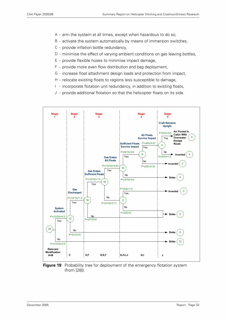
CAA Paper 2005/06 Summary Report on Helicopter Ditching and Crashworthiness Research
A - arm the system at all times, except when hazardous to do so,B - activate the system automatically by means of immersion switches,C - provide inflation bottle redundancy,D - minimise the effect of varying ambient conditions on gas leaving bottles,E - provide flexible hoses to minimise impact damage,F - provide more even flow distribution and bag deployment,G - increase float attachment design loads and protection from impact,H - relocate existing floats to regions less susceptible to damage,I - incorporate flotation unit redundancy, in addition to existing floats,J - provide additional flotation so that the helicopter floats on its side.
Figure 19 Probability tree for deployment of the emergency flotation system (from [28]).
24
12
12
12
2
10
6
4
Stage
1
Relevant
Modification
A+B C E,F D,E,F G,H,I,J G,I J
P=(12/24)=0.5
Stage
2
Stage
3
Stage
4
Stage
5
No
Yes
No
Yes
Yes
No
No
No
Yes
Yes
Yes
No
No
Yes
Yes
No
P=(12/24)=0.5
P=(0/12)=0
P=(12/12)=1.0
P=(0/12)=0
P=(12/12)=1.0
P=(2/12)=0.17
P=(10/12)=0.83
P=(0/2)=0
P=(2/2)=1.0
P=(4/10)=0.4
P=(6/10)=0.6
P=(4/6)=0.67
P=(2/6)=0.33
P=(4/4)=1.0
P=(0/4)=0.0
System
Activated
Gas
Discharged
Gas Enters
Sufficient Floats
Gas Enters
All Floats
Sufficient Floats
Survive Impact
All Floats
Survive Impact
Craft Remains
Upright
Sinks
Sinks
Sinks
Sinks
Inverted
Inverted
Inverted
Air Pocket In
Cabin With
Overwater
Escape
Route
0
12
0
2
4
2
4
0
Report Page 33December 2005
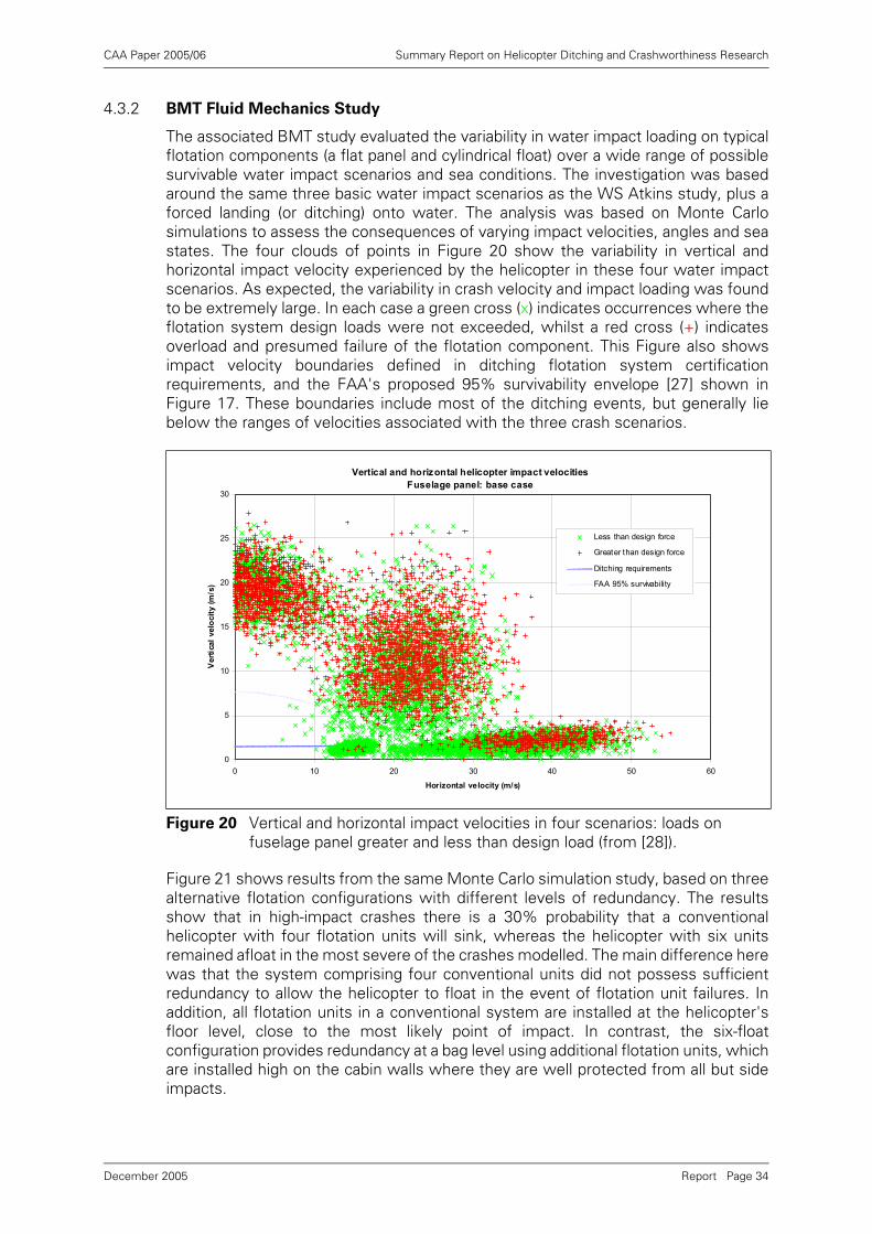
CAA Paper 2005/06 Summary Report on Helicopter Ditching and Crashworthiness Research
4.3.2 BMT Fluid Mechanics Study
The associated BMT study evaluated the variability in water impact loading on typicalflotation components (a flat panel and cylindrical float) over a wide range of possiblesurvivable water impact scenarios and sea conditions. The investigation was basedaround the same three basic water impact scenarios as the WS Atkins study, plus aforced landing (or ditching) onto water. The analysis was based on Monte Carlosimulations to assess the consequences of varying impact velocities, angles and seastates. The four clouds of points in Figure 20 show the variability in vertical andhorizontal impact velocity experienced by the helicopter in these four water impactscenarios. As expected, the variability in crash velocity and impact loading was foundto be extremely large. In each case a green cross (x) indicates occurrences where theflotation system design loads were not exceeded, whilst a red cross (+) indicatesoverload and presumed failure of the flotation component. This Figure also showsimpact velocity boundaries defined in ditching flotation system certificationrequirements, and the FAA's proposed 95% survivability envelope [27] shown inFigure 17. These boundaries include most of the ditching events, but generally liebelow the ranges of velocities associated with the three crash scenarios.
Figure 21 shows results from the same Monte Carlo simulation study, based on threealternative flotation configurations with different levels of redundancy. The resultsshow that in high-impact crashes there is a 30% probability that a conventionalhelicopter with four flotation units will sink, whereas the helicopter with six unitsremained afloat in the most severe of the crashes modelled. The main difference herewas that the system comprising four conventional units did not possess sufficientredundancy to allow the helicopter to float in the event of flotation unit failures. Inaddition, all flotation units in a conventional system are installed at the helicopter'sfloor level, close to the most likely point of impact. In contrast, the six-floatconfiguration provides redundancy at a bag level using additional flotation units, whichare installed high on the cabin walls where they are well protected from all but sideimpacts.
Figure 20 Vertical and horizontal impact velocities in four scenarios: loads on fuselage panel greater and less than design load (from [28]).
Vertical and horizontal helicopter impact velocities
Fuselage panel: base case
0
5
10
15
20
25
30
0 10 20 30 40 50 60
Horizontal velocity (m/s)
Vert
ical
velo
cit
y (m
/s)
Less than design force
Greater than design force
Ditching requirements
FAA 95% survivability
Report Page 34December 2005
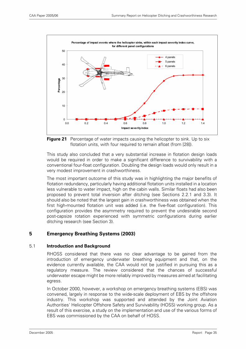
CAA Paper 2005/06 Summary Report on Helicopter Ditching and Crashworthiness Research
This study also concluded that a very substantial increase in flotation design loadswould be required in order to make a significant difference to survivability with aconventional four-float configuration. Doubling the design loads would only result in avery modest improvement in crashworthiness.
The most important outcome of this study was in highlighting the major benefits offlotation redundancy, particularly having additional flotation units installed in a locationless vulnerable to water impact, high on the cabin walls. Similar floats had also beenproposed to prevent total inversion after ditching (see Sections 2.2.1 and 3.3). Itshould also be noted that the largest gain in crashworthiness was obtained when thefirst high-mounted flotation unit was added (i.e. the five-float configuration). Thisconfiguration provides the asymmetry required to prevent the undesirable secondpost-capsize rotation experienced with symmetric configurations during earlierditching research (see Section 3).
5 Emergency Breathing Systems (2003)
5.1 Introduction and Background
RHOSS considered that there was no clear advantage to be gained from theintroduction of emergency underwater breathing equipment and that, on theevidence currently available, the CAA would not be justified in pursuing this as aregulatory measure. The review considered that the chances of successfulunderwater escape might be more reliably improved by measures aimed at facilitatingegress.
In October 2000, however, a workshop on emergency breathing systems (EBS) wasconvened, largely in response to the wide-scale deployment of EBS by the offshoreindustry. This workshop was supported and attended by the Joint AviationAuthorities' Helicopter Offshore Safety and Survivability (HOSS) working group. As aresult of this exercise, a study on the implementation and use of the various forms ofEBS was commissioned by the CAA on behalf of HOSS.
Figure 21 Percentage of water impacts causing the helicopter to sink. Up to six flotation units, with four required to remain afloat (from [28]).
Percentage of impact events where the helicopter sinks, within each impact severity index curve,
for different panel configurations
0
10
20
30
40
50
0.0 0.2 0.4 0.6 0.8 1.0 1.2 1.4
Impact severity index
Per
cen
tage
4 panels
5 panels
6 panels
Report Page 35December 2005
CAA Paper 2005/06 Summary Report on Helicopter Ditching and Crashworthiness Research
5.2 EBS Implementation and Use Study
This study [29] was undertaken by Dr Susan Coleshaw, who had previouslyperformed the side-floating helicopter human factors study while employed withRGIT Limited (see Section 3.3.5).
Published data on helicopter water impact accidents were analysed to determine thefrequency of different impact conditions and the incidence of drowning. Evidencefrom accident reports indicated that the helicopter inverted or sank immediately orafter a short delay in about 60% of all water impacts. If a helicopter does capsize itwill generally invert to a position where all the exits are underwater, meaning thatthose who survive the water impact must make an immediate underwater escape.Survivors have to cope with in-rushing water, cold shock, severe disorientationcaused by inversion, difficulties in releasing seat belts, and then locating and openingexits.
The high incidence of drowning is largely due to cold shock, which greatly reducesbreath-hold time and thus limits the time available for escape. EBS are designed tohelp overcome cold shock by allowing individuals to breathe underwater for a shorttime, thus extending underwater survival time. In this way EBS can provide a meansof bridging the gap between maximum breath-hold time and escape time, and thusreduce the incidence of drowning.
The risks from an accident in UK waters are potentially more serious than in moretemperate waters due to the higher risk of cold shock. Flights for the oil and gasindustry nonetheless differ from other civilian flights as all passengers are flying in anoccupational role. They wear protective immersion suits and receive training onsurvival in the event of an accident. Thus, while conditions may be more severe, thechances of making a successful escape are improved by the training, and by the levelof personal protection provided to individuals.
The report considered that reliance on EBS for escape should be minimised, butnoted that successful use of EBS can reduce levels of stress experienced duringhelicopter escape under simulated conditions. Satisfactory performance of EBS does,however, depend on good design, reliability of the equipment, ease of use andperformance on demand. Other key factors include individual human capabilities,training, environmental conditions, helicopter design, and the circumstances of thehelicopter accident.
Training is required to maximise the benefits of EBS and minimise the risk of humanerror during deployment and operation. When reviewing current knowledge on EBSequipment, particular attention was given to the testing and development of twoproducts: a re-breather and a compressed gas system. The report discussed thebackground and rationale behind their selection.
An example draft technical standard was also prepared, identifying minimumperformance requirements to ensure that equipment is manufactured to consistentand satisfactory standards, and that basic health and safety requirements are met.Compatibility with other personal protective equipment was also considered to be animportant issue that a technical standard would address.
The main conclusions from the study were that EBS could provide a viable solution tobridge the gap between breath-hold time and escape time, but that careful attentionwould have to be paid to equipment design and user training. The studyrecommended that a technical standard should be produced for EBS, and highlightedthe knowledge gaps that would need to be filled.
Report Page 36December 2005
CAA Paper 2005/06 Summary Report on Helicopter Ditching and Crashworthiness Research
At the end of this study the CAA reviewed its policy with respect to EBS, andconcluded that there was no compelling case to either mandate or ban the use ofEBS. The CAA also decided not to produce a formal design specification, largelybecause it is not normal practice to do so for non-mandated equipment. The finalreport on the study, including the example draft technical standard, was published inCAA Paper 2003/13 [29].
6 Future Regulatory and Research Activities
6.1 HOSS and WIDDCWG Recommendations (2000)
The CAA presented the findings from its ditching and water impact research to theJAA Helicopter Offshore Safety and Survivability (HOSS) working group and to theFAA/ JAA/Industry Joint Harmonisation Working Group (JHWG) on Water Impact,Ditching Design and Crashworthiness (WIDDCWG). The HOSS group produced aworking paper [30], reproduced in Appendix F of this report, and the WIDDCWGproduced a report [31], reproduced in Appendix G.
Both working groups recommended changes to current JAR/FAR 27 and 29airworthiness requirements relating to helicopter ditching and water impactcrashworthiness. HOSS noted that occupant survivability considerations do not takeaccount of service experience, and that accepted methods for demonstratingcompliance and determining flotation stability are no longer considered to beacceptable.
Similar recommendations came from both groups, and composite recommendationsrelevant to this report include the following:
• The current interpretation of 'reasonably probable water conditions' for ditchingequipment certification should be amended to take account of regional climatic seaconditions. Having regard to current FAA and JAA operating rules, and industryrequirements for straightforward certification standards, the followingrecommendations were made:
° In non-hostile environments, emergency flotation equipment should be thestandard, and the current interpretation based on sea state 4 was consideredto be appropriate.
° In hostile environments, a higher standard of sea state 6 should be requiredfor ditching equipment certification.
° Capsize boundary targets should be defined in terms of significant waveheight, zero crossing period and wave spectrum shape rather than sea statenumber.
• Flotation stability should be substantiated by representative model testing inirregular waves, with an appropriate exposure period and target probability ofcapsize. Associated standard test conditions and a standard test protocol, withpass/ fail criteria, should be developed and adopted.
• Structural ditching requirements should not be expanded to considercrashworthiness, because of the high variability in impact loads, and the highmagnitude of impact loads in survivable accidents, which can be too high to designfor in a practical manner.
• The flotation system should be automatically activated on sensing waterimmersion (to include automatic arming where appropriate), and the possibilitiesfor disabling automatic float activation (during any flight over water) should beminimised.
Report Page 37December 2005
CAA Paper 2005/06 Summary Report on Helicopter Ditching and Crashworthiness Research
• The flotation stability benefits of fitting scoops to flotation bags should beidentified in guidance material.
• The potential benefits of the side-floating helicopter concept, in respect of post-ditching capsize, should be recognised, and support for its further developmentshould be given. JHWG should consider incorporating this concept into therequirements once research has been completed, if shown to be technicallyfeasible and economically justifiable.
• The costs and expected benefits/ disbenefits should be established for redundantflotation units configured to produce a side-floating helicopter following capsize.
• Appropriate requirements/ advisory material should be generated and adopted toreflect current practice in terms of EFS crashworthiness.
• In view of the disparity between breath hold capability and escape time, theregulatory need and expected benefits/ disbenefits of EBS, for enhancingprospects of successful egress from an inverted and flooded cabin, should beestablished as a matter of urgency.
The papers produced by the HOSS and the WIDDCWG were submitted to the JHWG(later renamed the Rotorcraft Steering Group (RSG)) in June 2000. Having reviewedand debated both papers, the JHWG concluded that there remained somecontroversial issues that required further research. To ensure that progresscontinued, however, the JHWG committed in June 2001 to progressing thoserecommendations where full consensus within the working groups had beenachieved. The issues were split into those requiring changes to the advisory materialonly, and those involving rule changes. The JHWG was empowered to progress theformer, but the latter had to be endorsed by the JAA Harmonisation ManagementTeam (HMT) and the FAA Regulatory Council prior to requesting the AviationRulemaking Advisory Committee (ARAC) to form a working group. The HMTsubsequently endorsed the setting up of a rulemaking group in February 2002, but theFAA Regulatory Council, despite support from the FAA Rotorcraft Directorate,declined to progress this issue in the short-term due to its low priority status (fromtheir perspective) and lack of resources. Unfortunately, and largely due to the eventsof 9/11 in the USA, little progress has been made since then.
It was originally considered desirable to run the working groups covering the advisorymaterial and the rule changes in parallel in order to make the most efficient use ofresources. In June 2003, however, due to the lack of progress on the rule changeproposal, the RSG agreed to initiate work on the advisory material separately. At thetime of writing, AC material is in draft form. In addition, both regulatory activities(advisory material and rule changes) are listed on EASA's 2005/2007 FutureRulemaking Plan.
6.2 Future Work
Although the CAA believes that an improvement in the sea-keeping performance ofditched helicopters is practical at reasonable cost, it is recognised that it is not realisticto expect helicopters to remain upright in the more severe conditions experienced inthe northern North Sea, in the event of water impact, or due to post ditching aspectsother than stability. The RHOSS Report noted that all drownings that had occurred inoffshore helicopter accidents had been associated with water impacts rather thanditchings.
In view of this, and the results of the ditching and water impact research describedabove, the CAA believes that the side-floating helicopter concept has significantpotential to address both the ditching and water impact safety issues. CAA therefore
Report Page 38December 2005

CAA Paper 2005/06 Summary Report on Helicopter Ditching and Crashworthiness Research
recommends that this work be progressed by commissioning a helicopter type-specific design study. The purpose of this study will be to address the areas ofconcern highlighted by the WIDDCWG and HOSS reports.
7 Conclusions
The reports covering the various helicopter ditching and water impact researchactivities described in this document each contain their own detailed conclusions. Forclarity, this section comprises a summary of the major overall conclusions only.
7.1 Ditching
• Demonstration of compliance with the certification requirements for helicopterditching (JAR/FAR 27/29.801) in respect of flotation stability through model testingin regular waves is unreliable. The associated Advisory Circular (AC) materialshould be revised to specify testing in irregular waves with an appropriateexposure period and target probability of capsize.
• The present reference to sea state 4 as the “reasonably probable water condition”in the ditching certification AC material is unsatisfactory as a global standard, andshould be replaced with a requirement for the designer to select a sea state withan appropriately low probability of exceedance in the intended area of operation.The sea conditions should be defined in terms of a significant wave height, zerocrossing wave period and wave spectrum.
• Float scoops fitted to emergency floats can significantly enhance flotation stabilityat minimal cost and weight and should be recommended in the ditchingcertification AC material.
• Model tests on helicopters with raised floats (the 'wet floor' scheme) wereinconclusive. The effect on static stability was found to be very variable, dependingon helicopter weight and type. No consistent improvement in resistance to capsizein waves was found either.
• The upper practical capsize limit for helicopters lies in the region of sea state 5 or6, but there is a significant risk of ditching in seas greater than sea state 6 in someareas of operation (e.g. the northern North Sea). Other circumstances, such asdamaged or malfunctioning flotation equipment, or imperfect alighting onto thesea (e.g. due to tail rotor failure), may also lead to capsize in more moderate seas.
• A potential way to mitigate the consequences of post-ditching capsize would be tolocate additional flotation devices high on the fuselage in the vicinity of the mainrotor gearbox and engines, with the aim of preventing total inversion of thehelicopter following capsize. This 'side-floating' scheme serves to retain an airspace within the cabin thereby removing the time pressure for escape, andensuring that some of the doors and windows that form the escape routes remainabove the water level facilitating egress.
• Practical trials of the human factors aspects of escape from a side-floatinghelicopter using a helicopter underwater escape trainer (HUET) concluded that“... the evidence suggests that the occupant of a side-floating helicopter has amuch better chance of escape and survival than someone inside a fully invertedaircraft”.
Report Page 39December 2005
CAA Paper 2005/06 Summary Report on Helicopter Ditching and Crashworthiness Research
7.2 Crashworthiness
• The primary cause of loss of life in helicopter water impacts is drowning. Occupantfatalities resulting from excessive crash forces or as a result of structural collapseare a secondary issue.
• Designing the airframe to remain afloat for sufficient time to enable evacuationfollowing a water impact should be a major objective if survival is to be improved.
• A high-level cost-benefit analysis based on historical accident data indicated thatthe most cost-effective means of significantly improving post water impactflotation is automatic arming and activation of emergency flotation systems. Theprovision of additional flotation equipment to prevent total inversion followingcapsize (the 'side-floating' scheme) was judged to be the second most cost-effective measure.
• A computer modelling study based on simplified empirical and theoretical formulaeindicated that the most effective means of mitigating the consequences ofsurvivable water impacts is through the provision of redundancy in the emergencyflotation system. For the purposes of the study, redundancy was provided by theadditional flotation bags required for implementation of the 'side-floating' scheme.
7.3 General
• Overall, the single most effective means of improving occupant survival in theevent of a post-ditching capsize or a survivable water impact is through theprovision of additional flotation devices to prevent total inversion following capsize.
• Further work is required to confirm the technical feasibility and economic viabilityof the side-floating scheme. This should consist of a detailed design study for themodification of the EFS of a specific helicopter type.
• Emergency breathing systems (EBS) are capable of significantly extendingunderwater survival time, and can provide a means of bridging the gap betweenbreath-hold time and escape time. Although not considered to be as effective asthe 'side-floating' helicopter approach, particularly in the event of water impact,EBS could provide short-term mitigation pending the implementation of the 'side-floating' scheme, or an alternate solution in the event that the 'side-floating'scheme proves to be impractical for retro-fit to existing helicopters.
Report Page 40December 2005
CAA Paper 2005/06 Summary Report on Helicopter Ditching and Crashworthiness Research
8 Abbreviations
AC Advisory Circular
ARAC Aviation Rulemaking Advisory Committee
BCAR British Civil Airworthiness Requirements
BHC British Hovercraft Corporation
BMT BMT Fluid Mechanics Limited/ BMT Offshore Ltd.
CAA (UK) Civil Aviation Authority
CAP Civil Aviation Publication
EASA European Aviation Safety Agency
EBS Emergency breathing systems
EFS Emergency flotation systems
FAA (US) Federal Aviation Administration
FAR (US) Federal Airworthiness Regulations
HARP Helicopter Airworthiness Review Panel
HMT JAA Harmonisation Management Team
HOSS (JAA) Helicopter Offshore Safety and Survivability working group
HUET Helicopter underwater escape trainer
IOS Institute of Oceanographic Sciences
JAA (European) Joint Aviation Authorities
JAR (European) Joint Aviation Requirements
JHWG (FAA/JAA) Joint Harmonisation Working Group
NTSB (US) National Transportation Safety Board
RGIT RGIT Limited
RHOSS Review of Helicopter Offshore Safety and Survival
RSG Rotorcraft Steering Group
UK United Kingdom
UKCS United Kingdom Continental Shelf
US(A) United States of America
WHL GKN-Westland Helicopters Limited
WIDDCWG (JHWG) Working Group on Water Impact, Ditching Design and Crashworthiness
Report Page 41December 2005
CAA Paper 2005/06 Summary Report on Helicopter Ditching and Crashworthiness Research
9 References
[1] Civil Aviation Authority, Review of Helicopter Airworthiness, HelicopterAirworthiness Review Panel (HARP) of the Airworthiness Requirements Board,CAP 491, London, June 1984.
[2] Civil Aviation Authority, Review of Helicopter Offshore Safety and Survival(RHOSS), CAP 641, London, February 1995.
[3] Rowe, S.J., Howson, D., and Sparkes, P., Research Improving the Safety ofOffshore Helicopter Operations, Offshore Technology Conference paper no.OTC 14162, Houston, 2002.
[4] Rowe, S.J., and Howson, D., Research Improving the Safety of OffshoreHelicopter Operations - an Update, Marine Technology, Vol. 42, No. 1, pp. 31-33,January 2005.
[5] BMT Offshore Ltd., Review of Helicopter Ditching Performance, BMT Offshorereport no. 44011r12, July 1993. (Reproduced in Appendix A)
[6] BMT Offshore Ltd., Review of Helicopter Ditching Certification Requirements,BMT Offshore report no. 44011r21, July 1993. (Reproduced in Appendix B1)
[7] BMT Offshore Ltd., Review of Helicopter Ditching - A Potential ProbabilisticMethodology, BMT Offshore report no. 44011r31, August 1993. (Reproduced inAppendix C)
[8] Civil Aviation Authority, Helicopter Ditching Survival Aspects, CAA-SRG internalreport ref. 9/31/R50-11C-3, September 1989.
[9] British Hovercraft Corporation, Study of Float Positioning, BHC draft report no.X/O/3282, November 1985.
[10] British Hovercraft Corporation, Helicopter Flotation Stability: An Investigationinto the Effect of Fitting Water Scoops onto Emergency Floats, BHC report no.X/O/3257, April 1986.
[11] Westland Helicopters Limited, Feasibility of Fitting Scoops, WHL report no. WER143-20-00816, April 1986.
[12] Carter, D.J.T., and Brice, A.A., On Estimating the Probability that a DitchedHelicopter will be Capsized by Wave Action, Institute of Oceanographic Sciencesreport to the CAA, January 1987.
[13] Kidwell, J.C., and Crago, W.A., Model Testing to Establish Ditching and FlotationStability Characteristics of Helicopters, American Helicopter Society, 26thAnnual National Forum, Washington DC, June 1970.
[14] Civil Aviation Authority, Helicopter Float Scoops, CAA Paper 95010, London,December 1995.
[15] BMT Fluid Mechanics Limited, Helicopter Ditching JAR CertificationRequirements, BMT Fluid Mechanics report no. 44035r32, November 1995.(Reproduced in Appendix B2)
[16] BMT Fluid Mechanics Limited, Helicopter Ditching Certification Requirements -Alternative Model Testing Cost Estimates, BMT Fluid Mechanics report no.44117r12, November 1996. (Reproduced in Appendix D)
[17] BMT Fluid Mechanics Limited, Wave Height Probabilities on Helicopter Routes,BMT Fluid Mechanics report no. 44140r13, July 1997. (Reproduced inAppendix E1)
Report Page 42December 2005
CAA Paper 2005/06 Summary Report on Helicopter Ditching and Crashworthiness Research
[18] BMT Fluid Mechanics Limited, The Ditching of G-TIGK - 19/1/95, BMT FluidMechanics report no. 44140r21, November 1997. (Reproduced in Appendix E2)
[19] Williams, D.L., Contract No. 7D/S/865, Helicopter Ditching, Item 1.1, Wet FloorTechnique, report no. DW/CAA/01, January 1991.
[20] Rowe, S.J., and Howson, D., Helicopter Emergency Flotation Systems - SomeRecent Research, Proc. 17th Conf. on Offshore Search and Rescue, Marine andAviation Safety and Communications, Aberdeen, October 1998.
[21] Civil Aviation Authority, Devices to Prevent Helicopter Total Inversion Followinga Ditching, CAA Paper 97010, London, December 1997.
[22] Civil Aviation Authority, Helicopter Ditching Research - Egress from Side-FloatingHelicopters, CAA Paper 2001/10, London, September 2001.
[23] Westland Helicopters Limited, A Review of UK Military and World CivilHelicopter Water Impacts over the Period 1971-1992, Stress Department reportno. SDR 146, November 1993, published in CAA Paper 96005.
[24] Westland Helicopters Limited, An Analysis of the Response of HelicopterStructures to Water Impact, Stress Department report SDR 156, March 1995,published in CAA Paper 96005.
[25] Federal Aviation Administration, Rotorcraft Ditchings and Water Related Impactsthat Occurred from 1982 to 1989 - Phase I, US Department of Transportation,Federal Aviation Administration Technical Center report no. DOT/FAA/CT-92/13,1993.
[26] Federal Aviation Administration, Rotorcraft Ditchings and Water Related Impactsthat Occurred from 1982 to 1989 - Phase II, US Department of Transportation,Federal Aviation Administration Technical Center report no. DOT/FAA/CT-92/14,1993.
[27] Federal Aviation Administration, Survey and Analysis of Rotorcraft FlotationSystems, US Department of Transportation, Office of Aviation Research, reportno. DOT/FAA/AR-95/53, 1996.
[28] Civil Aviation Authority, Crashworthiness of Helicopter Emergency FlotationSystems, CAA Paper 2001/2, London, August 2001.
[29] Civil Aviation Authority, Preliminary Study on the Implementation and Use ofEmergency Breathing Systems, CAA Paper 2003/13, London, October 2003.
[30] Civil Aviation Authority, Offshore Operations - Helicopter Safety and OccupantSurvivability Following Ditching or Water Impact, JAA Helicopter Offshore Safety& Survivability Working Group (HOSS) - Working Paper HOSS/WP-99/8.5, June2000. (Reproduced in Appendix F)
[31] Civil Aviation Authority, Report of the JAA/FAA Joint Harmonisation WorkingGroup on Water Impact, Ditching Design and Crashworthiness, January 2000.(Reproduced in Appendix G)
Report Page 43December 2005
CAA Paper 2005/06 Summary Report on Helicopter Ditching and Crashworthiness Research
Appendix A Review of Helicopter Ditching
Performance
Executive Summary
BMT Offshore Ltd. was asked by the Civil Aviation Authority to perform a review of helicopterditching performance.
The review was to look critically at the various research reports and review documents thatCAA had commissioned in recent years, and to summarise and comment on their findings.
The stated objective in the certification of a helicopter in relation to ditching in the sea is thatthe helicopter should remain upright for sufficient time for the occupants to escape (say 5minutes). This implies that there should be an acceptably low probability of meeting a wavelarge enough to capsize the helicopter in this short period of time. The probability ofexperiencing a capsize is dependent on two key factors:
a) The height and period or slope of wave required to capsize the helicopter, and
b) the probability of experiencing such a wave, or larger, during the exposure period.
This report concludes that the more important gaps in current understanding lie in the firstcategory rather than the second. Attempts to correlate the dynamic stability in waves ofdifferent helicopter types with their physical and static stability properties have identified someweak relationships, but there is a lack of confidence that this information could be used todesign modifications that would be guaranteed to result in improved performance in a seaway.Further theoretical and computer simulation work is required to confirm these basicdependencies.
However, there is clear evidence that helicopter resistance to capsize could be improved bythe addition of float scoops.
Raising flotation so that the helicopter floats at a lower level in the water (the `wet floor'approach) does not currently enjoy evidence to support it as an improving measure, but thismay be due to a lack of understanding on exactly how the floats should be positioned.
The attachment of floats to the engine cowling can prevent permanent complete inversion ofthe helicopter and permits the helicopter to float in a stable side-on attitude following any initialcapsize.
This report presents a number of conclusions on the results of the research work to-date, andalso makes recommendations about further work aimed at reducing the risk of capsize.
Appendix A Page 1December 2005
CAA Paper 2005/06 Summary Report on Helicopter Ditching and Crashworthiness Research
1 Introduction
BMT Offshore Ltd. (BMT) was asked [1]1 by the Civil Aviation Authority (CAA) topropose a review of helicopter ditching performance. BMT responded with a proposal[2], and based on this proposal, CAA put in place a contract for the work to beperformed [3].
The review was to look critically at the various research reports and reviewdocuments that CAA had commissioned in recent years, and to summarise andcomment on their findings.
1.1 Objectives
The objectives of the overall study were stated to be [2] as follows:
a) Perform a critical review of a number of documents (Refs [4] - [8]) with theobjective of drawing conclusions from this work and prepare an overviewdocument (or documents) suitable for publication by CAA.
b) Perform a critical review of the current UK Emergency Alighting on Waterhelicopter design requirements as specified by BCAR Paper No G779 dated 7thOctober 1985, and where appropriate make recommendations on how theserequirements might be improved, and whether there are better ways of assessinga helicopter's water-borne stability.
c) Based on the results of (a) and (b) above, and the results of a separate study,review North Sea helicopter ditching performance over the past 20 years andassess the practicality of imposing a new probability-based methodology for NorthSea helicopter operations, taking account of specific type's ditching rates, capsizeprobability and operating environment.
This first report deals with the results of (a) above only.
1.2 Background
The stated objective [7] in the certification of a helicopter in relation to ditching in thesea is that the helicopter should remain upright for sufficient time for the occupantsto escape (say 5 minutes). This implies that there should be an acceptably lowprobability of meeting a wave large enough to capsize the helicopter in this shortperiod of time.
The probability of experiencing a capsize is dependent on two key factors:
a) The height and period or slope of wave required to capsize the helicopter, and
b) the probability of experiencing such a wave, or larger, during the exposure period.
This report reviews the current understanding on these two factors as evidenced bythe contents of references [4] - [8]. It attempts to draw attention to the gaps in currentunderstanding and thus recommend where further research work should be directed.
2 Conclusions and Recommendations
The study has attempted to identify the key issues influencing the ability ofhelicopters to resist capsize whilst floating on the surface of the seas followingditching. The issues identified, and the implications for future work or regulatoryactivity, are outlined in the following:
1. References are to be found in Section 9 on Page 30.
Appendix A Page 2December 2005
CAA Paper 2005/06 Summary Report on Helicopter Ditching and Crashworthiness Research
2.1 Conclusions
2.1.1 This study has only considered helicopters that are floating upright and intact, andtherefore have presumably alighted on the water in a reasonably controlled manner.No consideration has been taken of the stability of helicopters that are damaged priorto, or in the course of, alighting on the water.
2.1.2 The results of model tests on some eight different helicopter types has been studied,many over a range of different weights and float configurations.
2.1.3 The model test reports [4] and [5], present the results of numerous tests in regularand irregular waves. Little or no attempt is made in these reports to interpret thecapsize boundary results in terms of the key factors influencing the static stabilityproperties of the helicopter or its other physical properties.
2.1.4 The results of these tests show that the helicopter types tested generally had littledifficulty in complying with the BCAR regular wave steepness criterion, but allcapsized in irregular waves less severe than the BCAR limit for stability investigationof sea-state 6.
2.1.5 The results of [4] and [5] have been re-analysed and re-presented in an attempt todiscover the major helicopter properties that influence capsize. The results of thisextensive exercise were generally disappointing, but there is some evidence that thefollowing assist in the prevention of capsize:
• greater helicopter weight;
• greater roll inertia;
• greater peak righting moment;
• greater area under righting moment curve;
• greater range of stability;
• greater helicopter beam;
• greater roll gyrates/beam.
Clearly a number of the above are interrelated.
2.1.6 Model tests of the type reported in [4] and [5] are extremely difficult to perform. Thecapsizing of the model helicopter is very sensitive to precise details of the model andprecise details of the waves. This may explain some of the difficulty experienced incorrelating the results.
2.1.7 Ideally such tests should provide a quantitative measure of the probability of capsizein a given duration of exposure to a given sea-state. However, this informationrequires many repeat runs in different realisations of the same wind and waveconditions in order to be reliable, and is thus very time-consuming and expensive. Theresults of such tests should however be much more useful than those described in[4] and [5].
2.1.8 It is clear that model tests in the presence of wind result in fewer capsizes. This isdue to a tendency to weather vane, i.e. turn into the winds and waves. Evidently anydevice (e.g. sea anchor) which promotes the adoption of a nose to wave heading isbeneficial to the survival of the helicopter.
2.1.9 The capsize of helicopters is essentially only caused by breaking waves. It is unlikelythat an undamaged helicopter will capsize in non breaking waves.
Appendix A Page 3December 2005
CAA Paper 2005/06 Summary Report on Helicopter Ditching and Crashworthiness Research
2.1.10 Ignoring the results of the model tests, consideration of the physical mechanism ofcapsize in a breaking wave suggests that the following properties of the helicopterwill enhance resistance to capsize:
• high roll inertia;
• large range of static stability;
• large angle of peak righting moment;
• low lateral resistance to movement through the water;
• low above water profile.
2.1.11 Model tests on float scoops have demonstrated a significant benefit in terms ofresistance to capsize on all but one helicopter type. It is not clear however, whetherthis benefit comes primarily from the improvements to the static stability curve, or tothe dynamic (inertia and damping) properties of the helicopter.
2.1.12 Work on the development of float scoops seems to have been halted due todifficulties in predicting the increased flotation loads. However, these loads shouldnot be any more difficult to predict using empirical data than the loads experienced byconventional floats.
2.1.13 Model tests on helicopter models with raised flotation (the ‘wet floor’ approach) havebeen inconclusive. The effect of raising the floats on the static stability of thehelicopter varies markedly depending on aircraft weight and type. The effect onresistance to capsize in waves is also very variable. It is likely that the new raisedlocation of the floats must be carefully chosen in order to obtain any beneficial effect.Further work is in progress on this issue.
2.1.14 Theoretical analysis of the likely influence of float ‘scoops’ [6] which has beenpreviously conducted is flawed because of a failure to incorporate basic wavekinematics into the model. However, proper numerical simulation of the behaviour ofa helicopter floating on the surface of the sea probably offers one of the bestopportunities to assist understanding of the capsize process and the helicopter andwave properties that influence it.
2.1.15 Work performed by IOS has demonstrated a method for estimating the probabilitythat a capsizing wave will be experienced in a given period of time chosen at random.This technique offers part of the answer in the search for a means for the estimationof the overall risk of capsize.
2.1.16 The results of the IOS work show probabilities of capsize in a 10 minute period in theNorth Sea of about 5% (it is not clear why 10 minutes was chosen, when the CAAstated period is 5 minutes). These results seem to be inconsistent with practicalexperience of ditchings, and the results of model tests in irregular waves which bothsuggest that this probability is more likely to be in the region of 30%. The selectionof the wave height capsize criterion assumed by IOS may be at fault.
2.1.17 The CAA has suggested [7] an objective for this probability of capsize following aditching of 1%.
2.1.18 Whilst it seems that significant improvements to resistance to capsize are possible(e.g. using scoops), it is difficult to imagine a practical design improvement that willguarantee an order of magnitude change to the current levels of probability of capsize.This implies that more serious consideration should be given to measures (such asengine cowling floats) that prevent a permanent inverted attitude following initialcapsize.
Appendix A Page 4December 2005
CAA Paper 2005/06 Summary Report on Helicopter Ditching and Crashworthiness Research
2.1.19 The apparent rejection of cowling floats on the basis of one model test, and possiblya faulty interpretation of the results of this model test, is unfortunate. This testdemonstrated that a stable side-floating condition could be maintained on an S76.There was, however, a tendency for the helicopter to roll through more than 270o, intwo stages, to reach this attitude, and previous writers have pointed to the danger toescaping personnel this represents. The author of this report does not agree with thisview, believing that the risk to escaping personnel is not greater than that representedby trying to escape during or following capsize to a fully inverted attitude, and that itis better to have the guarantee of an eventual floating attitude where there is at leastone escape hatch well above water level.
2.2 Recommendations - General
2.2.1 Future wave model tests performed on helicopters for certification or researchpurposes should concentrate on behaviour in long sequences of realistic irregularwaves so that the probability of capsize can be properly estimated.
2.2.2 Most of the evidence on probabilities of capsize for current helicopter types in theNorth Sea suggests that the risk of capsize is considerably higher than the CAA statedobjective. Therefore means should be sought to reduce this risk.
2.3 Recommendations for Further Work
2.3.1 The development of a time-domain computer simulation model of the motion of ahelicopter floating on waves is justified in terms of the understanding it is likely tobring of the main parameters controlling resistance to capsize. Earlier attempts at thisseem to have failed primarily due to the inexperience of the computer modellers withthe simulation of water wave processes.
Initial dynamic simulation work should concentrate on regular waves, but it isimportant that the methods chosen can be extended to breaking waves (using thebest available research on breaking wave kinematics) and to irregular wave spectra.
Work with the simulation model should concentrate on (a) attempting validationagainst model tests, and (b) using the simulation model to perform systematicvariations of stability properties.
Collaboration with those in possession of model tests on a fully instrumentedhelicopter model might be particularly beneficial in this context.
2.3.2 Consequently, it is recommended that an approach be made to the owners of theresults of some helicopter model tests conducted in the Marintek facilities in 1991,to see if they would be prepared to release some or all of their information. Theobjective would be discover whether the data could be used to validate theoreticalpredictions of helicopter motions on the point of capsize.
2.3.3 The concept of float scoops should be developed further because they appear toprovide significant benefit. It should not be necessary to wait for the results ofcomputer simulations in order to make reasonable estimates of the flotation loads.The work should also concentrate on establishing whether it is the static stability ordynamic effects of the scoops that are primarily responsible for the benefit, as thismay point the way to significant design improvements.
2.3.4 The ‘wet floor’ concept requires further detailed investigation before it can bedetermined whether, and how, floats should be raised on any individual helicoptertype. Initial steps in this direction are already in progress with the detailed hydrostaticmodelling of a partially flooded helicopter.
2.3.5 More serious attention should be given to measures (such as the cowling floats) thatprevent a permanent inverted attitude following initial capsize.
Appendix A Page 5December 2005
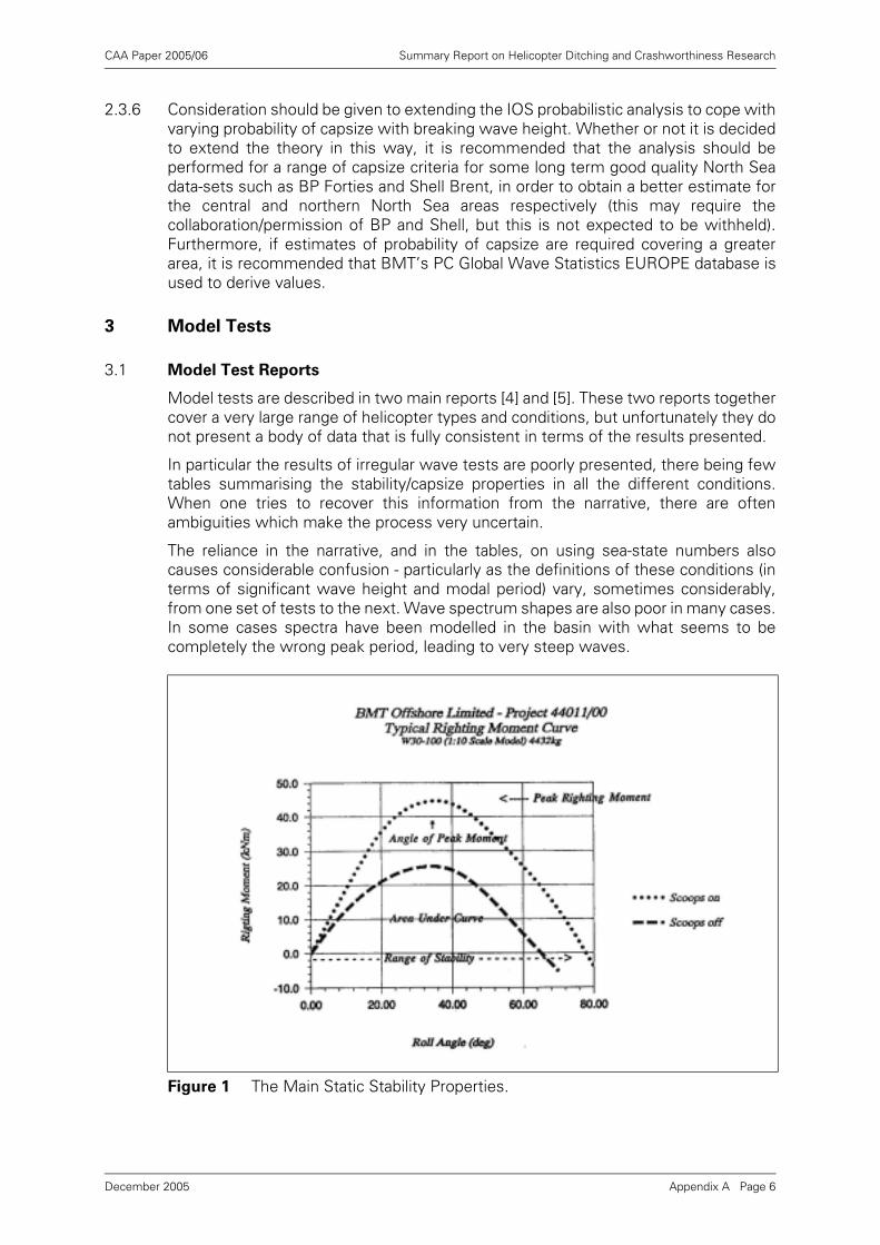
CAA Paper 2005/06 Summary Report on Helicopter Ditching and Crashworthiness Research
2.3.6 Consideration should be given to extending the IOS probabilistic analysis to cope withvarying probability of capsize with breaking wave height. Whether or not it is decidedto extend the theory in this way, it is recommended that the analysis should beperformed for a range of capsize criteria for some long term good quality North Seadata-sets such as BP Forties and Shell Brent, in order to obtain a better estimate forthe central and northern North Sea areas respectively (this may require thecollaboration/permission of BP and Shell, but this is not expected to be withheld).Furthermore, if estimates of probability of capsize are required covering a greaterarea, it is recommended that BMT’s PC Global Wave Statistics EUROPE database isused to derive values.
3 Model Tests
3.1 Model Test Reports
Model tests are described in two main reports [4] and [5]. These two reports togethercover a very large range of helicopter types and conditions, but unfortunately they donot present a body of data that is fully consistent in terms of the results presented.
In particular the results of irregular wave tests are poorly presented, there being fewtables summarising the stability/capsize properties in all the different conditions.When one tries to recover this information from the narrative, there are oftenambiguities which make the process very uncertain.
The reliance in the narrative, and in the tables, on using sea-state numbers alsocauses considerable confusion - particularly as the definitions of these conditions (interms of significant wave height and modal period) vary, sometimes considerably,from one set of tests to the next. Wave spectrum shapes are also poor in many cases.In some cases spectra have been modelled in the basin with what seems to becompletely the wrong peak period, leading to very steep waves.
Figure 1 The Main Static Stability Properties.
Appendix A Page 6December 2005
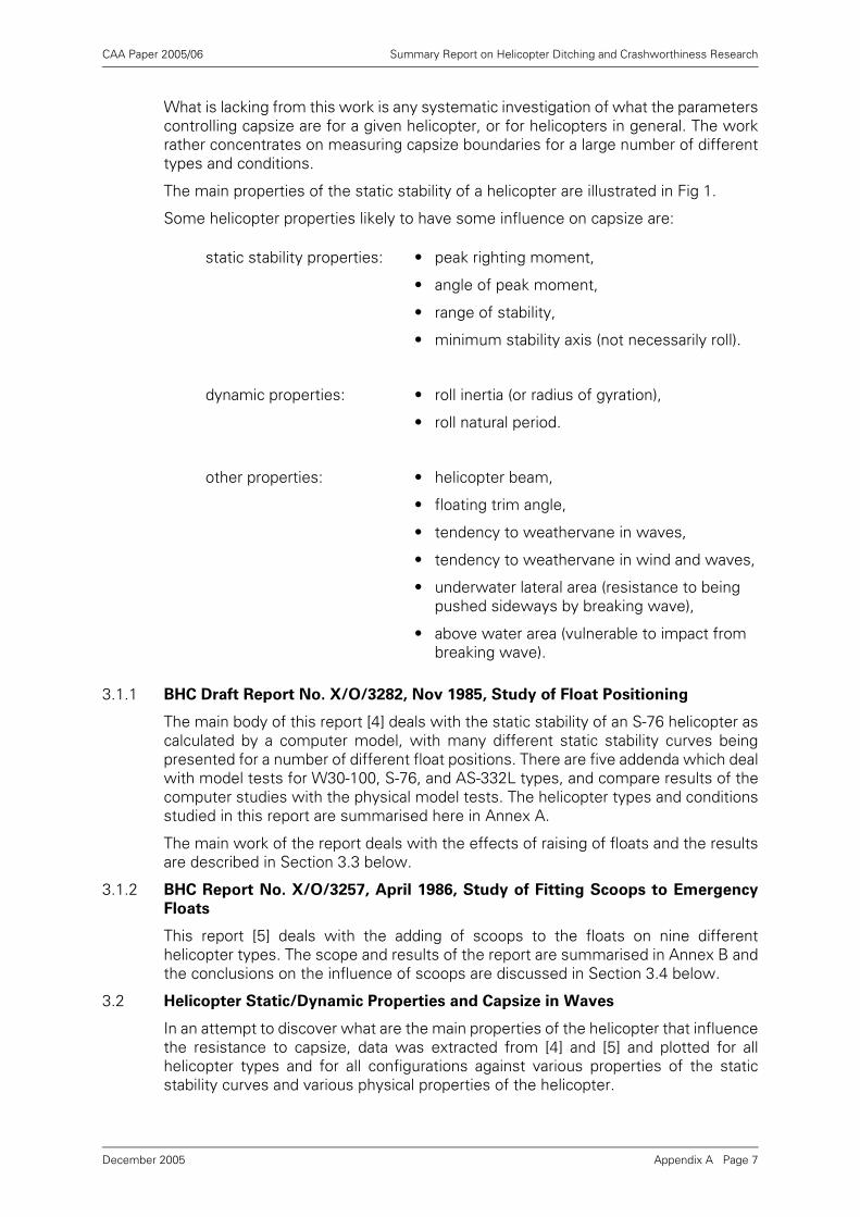
CAA Paper 2005/06 Summary Report on Helicopter Ditching and Crashworthiness Research
What is lacking from this work is any systematic investigation of what the parameterscontrolling capsize are for a given helicopter, or for helicopters in general. The workrather concentrates on measuring capsize boundaries for a large number of differenttypes and conditions.
The main properties of the static stability of a helicopter are illustrated in Fig 1.
Some helicopter properties likely to have some influence on capsize are:
3.1.1 BHC Draft Report No. X/O/3282, Nov 1985, Study of Float Positioning
The main body of this report [4] deals with the static stability of an S-76 helicopter ascalculated by a computer model, with many different static stability curves beingpresented for a number of different float positions. There are five addenda which dealwith model tests for W30-100, S-76, and AS-332L types, and compare results of thecomputer studies with the physical model tests. The helicopter types and conditionsstudied in this report are summarised here in Annex A.
The main work of the report deals with the effects of raising of floats and the resultsare described in Section 3.3 below.
3.1.2 BHC Report No. X/O/3257, April 1986, Study of Fitting Scoops to Emergency
Floats
This report [5] deals with the adding of scoops to the floats on nine differenthelicopter types. The scope and results of the report are summarised in Annex B andthe conclusions on the influence of scoops are discussed in Section 3.4 below.
3.2 Helicopter Static/Dynamic Properties and Capsize in Waves
In an attempt to discover what are the main properties of the helicopter that influencethe resistance to capsize, data was extracted from [4] and [5] and plotted for allhelicopter types and for all configurations against various properties of the staticstability curves and various physical properties of the helicopter.
static stability properties: • peak righting moment,
• angle of peak moment,
• range of stability,
• minimum stability axis (not necessarily roll).
dynamic properties: • roll inertia (or radius of gyration),
• roll natural period.
other properties: • helicopter beam,
• floating trim angle,
• tendency to weathervane in waves,
• tendency to weathervane in wind and waves,
• underwater lateral area (resistance to being pushed sideways by breaking wave),
• above water area (vulnerable to impact from breaking wave).
Appendix A Page 7December 2005
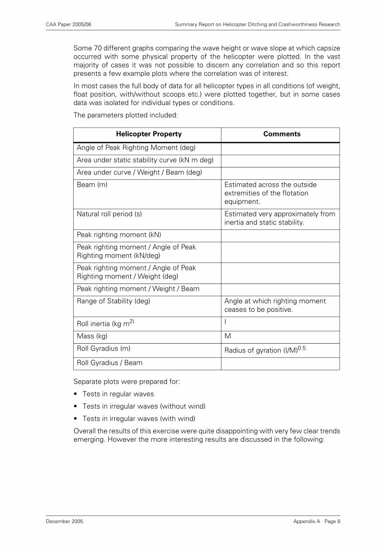
CAA Paper 2005/06 Summary Report on Helicopter Ditching and Crashworthiness Research
Some 70 different graphs comparing the wave height or wave slope at which capsizeoccurred with some physical property of the helicopter were plotted. In the vastmajority of cases it was not possible to discern any correlation and so this reportpresents a few example plots where the correlation was of interest.
In most cases the full body of data for all helicopter types in all conditions (of weight,float position, with/without scoops etc.) were plotted together, but in some casesdata was isolated for individual types or conditions.
The parameters plotted included:
Separate plots were prepared for:
• Tests in regular waves
• Tests in irregular waves (without wind)
• Tests in irregular waves (with wind)
Overall the results of this exercise were quite disappointing with very few clear trendsemerging. However the more interesting results are discussed in the following:
Helicopter Property Comments
Angle of Peak Righting Moment (deg)
Area under static stability curve (kN m deg)
Area under curve / Weight / Beam (deg)
Beam (m) Estimated across the outside extremities of the flotation equipment.
Natural roll period (s) Estimated very approximately from inertia and static stability.
Peak righting moment (kN)
Peak righting moment / Angle of Peak Righting moment (kN/deg)
Peak righting moment / Angle of Peak Righting moment / Weight (deg)
Peak righting moment / Weight / Beam
Range of Stability (deg) Angle at which righting moment ceases to be positive.
Roll inertia (kg m2) I
Mass (kg) M
Roll Gyradius (m) Radius of gyration (I/M)0.5
Roll Gyradius / Beam
Appendix A Page 8December 2005
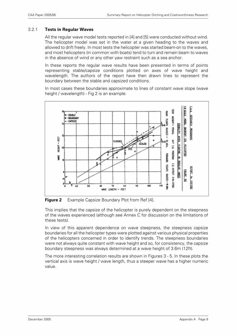
CAA Paper 2005/06 Summary Report on Helicopter Ditching and Crashworthiness Research
3.2.1 Tests in Regular Waves
All the regular wave model tests reported in [4] and [5] were conducted without wind.The helicopter model was set in the water at a given heading to the waves andallowed to drift freely. In most tests the helicopter was started beam-on to the waves,and most helicopters (in common with boats) tend to turn and remain beam to wavesin the absence of wind or any other yaw restraint such as a sea anchor.
In these reports the regular wave results have been presented in terms of pointsrepresenting stable/capsize conditions plotted on axes of wave height andwavelength. The authors of the report have then drawn lines to represent theboundary between the stable and capsized conditions.
In most cases these boundaries approximate to lines of constant wave slope (waveheight / wavelength) - Fig 2 is an example.
This implies that the capsize of the helicopter is purely dependent on the steepnessof the waves experienced (although see Annex C for discussion on the limitations ofthese tests).
In view of this apparent dependence on wave steepness, the steepness capsizeboundaries for all the helicopter types were plotted against various physical propertiesof the helicopters concerned in order to identify trends. The steepness boundarieswere not always quite constant with wave height and so, for consistency, the capsizeboundary steepness was always determined at a wave height of 3.6m (12ft).
The more interesting correlation results are shown in Figures 3 - 5. In these plots thevertical axis is wave height / wave length, thus a steeper wave has a higher numericvalue.
Figure 2 Example Capsize Boundary Plot from Ref [4].
Appendix A Page 9December 2005
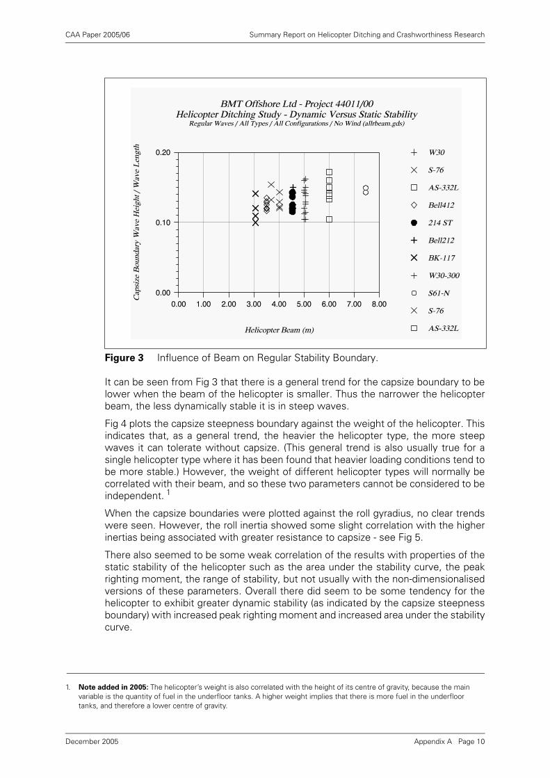
CAA Paper 2005/06 Summary Report on Helicopter Ditching and Crashworthiness Research
It can be seen from Fig 3 that there is a general trend for the capsize boundary to belower when the beam of the helicopter is smaller. Thus the narrower the helicopterbeam, the less dynamically stable it is in steep waves.
Fig 4 plots the capsize steepness boundary against the weight of the helicopter. Thisindicates that, as a general trend, the heavier the helicopter type, the more steepwaves it can tolerate without capsize. (This general trend is also usually true for asingle helicopter type where it has been found that heavier loading conditions tend tobe more stable.) However, the weight of different helicopter types will normally becorrelated with their beam, and so these two parameters cannot be considered to beindependent. 1
When the capsize boundaries were plotted against the roll gyradius, no clear trendswere seen. However, the roll inertia showed some slight correlation with the higherinertias being associated with greater resistance to capsize - see Fig 5.
There also seemed to be some weak correlation of the results with properties of thestatic stability of the helicopter such as the area under the stability curve, the peakrighting moment, the range of stability, but not usually with the non-dimensionalisedversions of these parameters. Overall there did seem to be some tendency for thehelicopter to exhibit greater dynamic stability (as indicated by the capsize steepnessboundary) with increased peak righting moment and increased area under the stabilitycurve.
Figure 3 Influence of Beam on Regular Stability Boundary.
1. Note added in 2005: The helicopter’s weight is also correlated with the height of its centre of gravity, because the main variable is the quantity of fuel in the underfloor tanks. A higher weight implies that there is more fuel in the underfloor tanks, and therefore a lower centre of gravity.
Appendix A Page 10December 2005
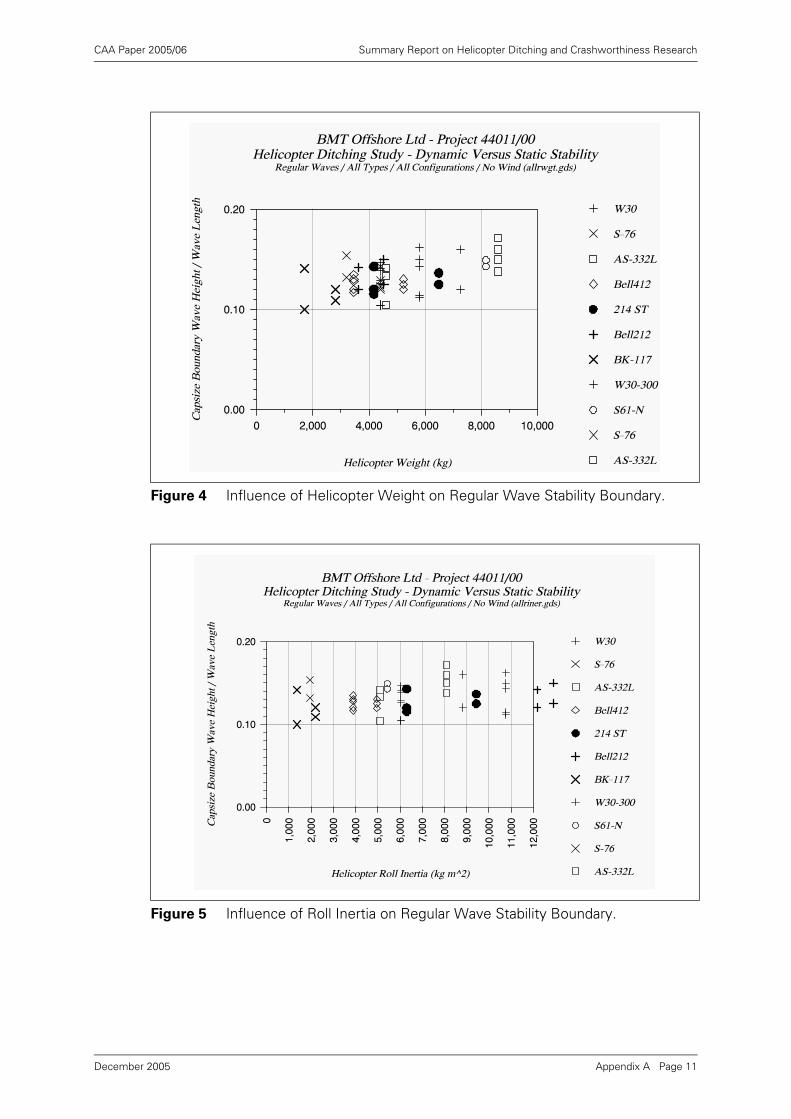
CAA Paper 2005/06 Summary Report on Helicopter Ditching and Crashworthiness Research
Figure 4 Influence of Helicopter Weight on Regular Wave Stability Boundary.
Figure 5 Influence of Roll Inertia on Regular Wave Stability Boundary.
Appendix A Page 11December 2005
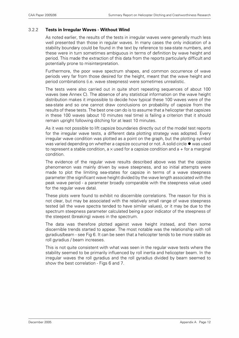
CAA Paper 2005/06 Summary Report on Helicopter Ditching and Crashworthiness Research
3.2.2 Tests in Irregular Waves - Without Wind
As noted earlier, the results of the tests in irregular waves were generally much lesswell presented than those in regular waves. In many cases the only indication of astability boundary could be found in the text by reference to sea-state numbers, andthese were in turn sometimes ambiguous in terms of definition by wave height andperiod. This made the extraction of this data from the reports particularly difficult andpotentially prone to misinterpretation.
Furthermore, the poor wave spectrum shapes, and common occurrence of waveperiods very far from those desired for the height, meant that the wave height andperiod combinations (i.e. wave steepness) were sometimes unrealistic.
The tests were also carried out in quite short repeating sequences of about 100waves (see Annex C). The absence of any statistical information on the wave heightdistribution makes it impossible to decide how typical these 100 waves were of thesea-state and so one cannot draw conclusions on probability of capsize from theresults of these tests. The best one can do is to assume that a helicopter that capsizesin these 100 waves (about 10 minutes real time) is failing a criterion that it shouldremain upright following ditching for at least 10 minutes.
As it was not possible to lift capsize boundaries directly out of the model test reportsfor the irregular wave tests, a different data plotting strategy was adopted. Everyirregular wave condition was plotted as a point on the graph, but the plotting symbolwas varied depending on whether a capsize occurred or not. A solid circle ! was usedto represent a stable condition, a × used for a capsize condition and a + for a marginalcondition.
The evidence of the regular wave results described above was that the capsizephenomenon was mainly driven by wave steepness, and so initial attempts weremade to plot the limiting sea-states for capsize in terms of a wave steepnessparameter (the significant wave height divided by the wave length associated with thepeak wave period - a parameter broadly comparable with the steepness value usedfor the regular wave data).
These plots were found to exhibit no discernible correlations. The reason for this isnot clear, but may be associated with the relatively small range of wave steepnesstested (all the wave spectra tended to have similar values), or it may be due to thespectrum steepness parameter calculated being a poor indicator of the steepness ofthe steepest (breaking) waves in the spectrum.
The data was therefore plotted against wave height instead, and then somediscernible trends started to appear. The most notable was the relationship with rollgyradius/beam - see Fig 6. It can be seen that a helicopter tends to be more stable asroll gyradius / beam increases.
This is not quite consistent with what was seen in the regular wave tests where thestability seemed to be primarily influenced by roll inertia and helicopter beam. In theirregular waves the roll gyradius and the roll gyradius divided by beam seemed toshow the best correlation - Figs 6 and 7.
Appendix A Page 12December 2005
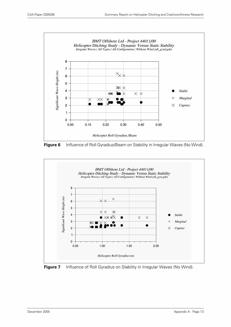
CAA Paper 2005/06 Summary Report on Helicopter Ditching and Crashworthiness Research
Figure 6 Influence of Roll Gyradius/Beam on Stability in Irregular Waves (No Wind).
Figure 7 Influence of Roll Gyradius on Stability in Irregular Waves (No Wind).
Appendix A Page 13December 2005
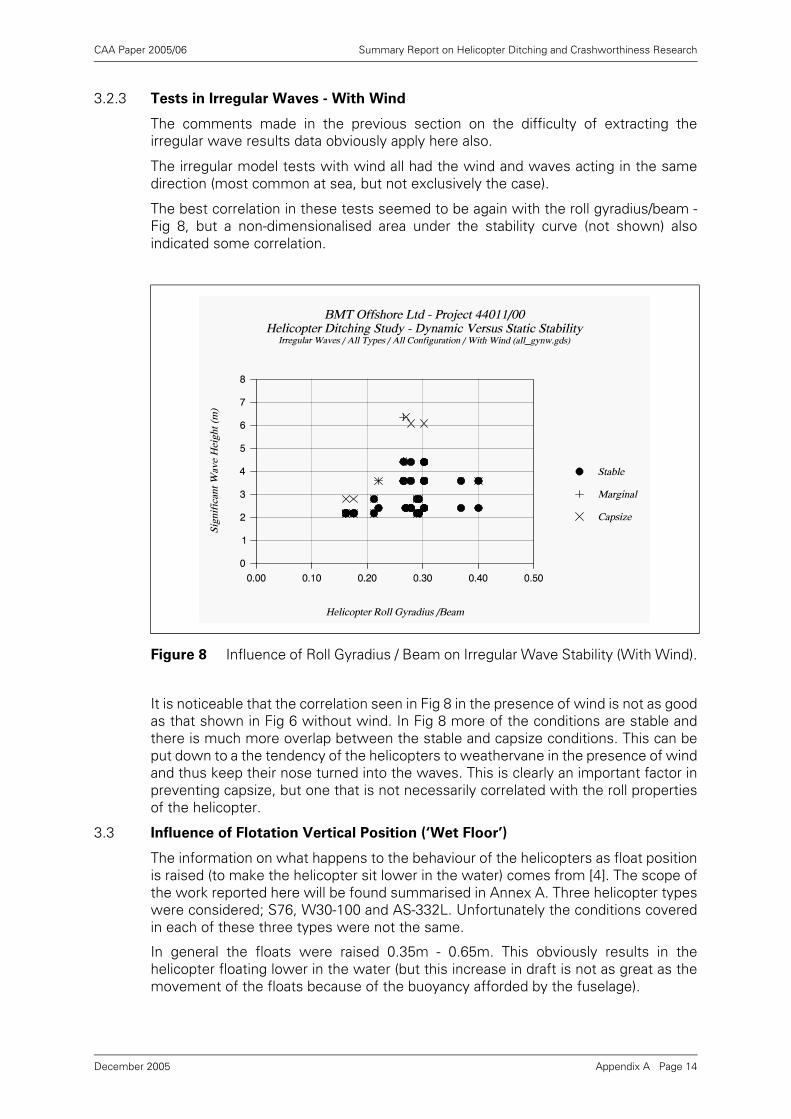
CAA Paper 2005/06 Summary Report on Helicopter Ditching and Crashworthiness Research
3.2.3 Tests in Irregular Waves - With Wind
The comments made in the previous section on the difficulty of extracting theirregular wave results data obviously apply here also.
The irregular model tests with wind all had the wind and waves acting in the samedirection (most common at sea, but not exclusively the case).
The best correlation in these tests seemed to be again with the roll gyradius/beam -Fig 8, but a non-dimensionalised area under the stability curve (not shown) alsoindicated some correlation.
It is noticeable that the correlation seen in Fig 8 in the presence of wind is not as goodas that shown in Fig 6 without wind. In Fig 8 more of the conditions are stable andthere is much more overlap between the stable and capsize conditions. This can beput down to a the tendency of the helicopters to weathervane in the presence of windand thus keep their nose turned into the waves. This is clearly an important factor inpreventing capsize, but one that is not necessarily correlated with the roll propertiesof the helicopter.
3.3 Influence of Flotation Vertical Position (‘Wet Floor’)
The information on what happens to the behaviour of the helicopters as float positionis raised (to make the helicopter sit lower in the water) comes from [4]. The scope ofthe work reported here will be found summarised in Annex A. Three helicopter typeswere considered; S76, W30-100 and AS-332L. Unfortunately the conditions coveredin each of these three types were not the same.
In general the floats were raised 0.35m - 0.65m. This obviously results in thehelicopter floating lower in the water (but this increase in draft is not as great as themovement of the floats because of the buoyancy afforded by the fuselage).
Figure 8 Influence of Roll Gyradius / Beam on Irregular Wave Stability (With Wind).
Appendix A Page 14December 2005
CAA Paper 2005/06 Summary Report on Helicopter Ditching and Crashworthiness Research
Static and dynamic tests were also performed with the cabin free flooding (doorsopen) and sealed. It is not clear from the results whether the sealed cases werefloating at a lower draft than the open cases and this is only obvious when the floatsare in their highest positions (e.g. configuration 9F for the S76 where all floats areraised 0.5m). Unfortunately, even in the best documented static conditions presentedfor the S76, the water line drawings do not show the location of the helicopter doors,and so it is not easy to determine the extent of cabin flooding that occurs when thedoors are opened.
Comparisons between static stability properties calculated by computer andmeasured on the physical models identified some quite marked differences in somecases, but these differences were not large enough to disguise the trends in staticstability resulting from the float position changes.
The movements of the various floats, the variations in helicopter weight and theopening/sealing of cabin doors result in a complex matrix of results which in turncause changes in helicopter draft, trim and the extent of internal flooding.Unfortunately the authors have not tried to interpret the results in terms of thesemore fundamental variations, and this makes it very difficult to understand theimportant controlling influences on the static stability.
However, it can be deduced that raising the floats always tends to increase the rangeof stability and the angle of peak righting moment. The effect on the peak rightingmoment itself is more uncertain - sometimes it is increased, sometimes reduced. Forthe S76 the peak righting moment increases as craft weight increases from 3193kgto 4401 kg, but then decreases as the weight further increases to 5399kg. This isexplained in the report in terms of the height of the centre of gravity above the waterline, but it is not clear why this height should increase again for heavier helicopterweights.
Permitting the craft to flood through the open doors tended to reduce both the rangeof stability and the peak righting moment for the S76 in all float configurations. For theW30 the reverse was true with the peak righting moment being increased when thecabin and tail boom were permitted to flood.
The effect of raising the floats on the W30 was considered to be beneficial to theresistance to capsize. On the S76 the improvements did not seem to be as clear, andit is interesting that the greatest benefit seemed to come from raising just the mainfloats whilst the static stability calculations had shown the greatest changes to staticstability occurred when the forward floats were raised.
The improvement in resistance to capsize when raising the floats on the AS-332L wasdisappointing. The effect of raising the floats on the static stability at the lighter4610kg weight had been quite marked (large reduction in peak righting moment, butincreased range of stability), whilst the effect at the heavier 8600kg weight was quitelimited. However, the performance in waves was improved at the heavier weight anddramatically worsened at the lighter weight.
It is clear that raising the main floats can have quite markedly different effects on thestatic stability depending on the helicopter type and the exact way it is done.Furthermore, the influence on the dynamic stability (or resistance to capsize) isdifficult to correlate with the changes in static stability.
Raising floats might well be a way of improving the performance of all helicoptertypes if it was known what static stability (or other) properties of the helicopter onewas trying to vary by the float movement, and in what way.
Appendix A Page 15December 2005
CAA Paper 2005/06 Summary Report on Helicopter Ditching and Crashworthiness Research
There is consequently a need for better understanding of the mechanism andpotential benefits and disbenefits of raised floats before recommendations are madethat encourage such float placement.
3.4 Influence of Scoops
The influence of adding scoops to the sides of the floats ought to be easier tounderstand and interpret than the raising of floats described in the preceding section.
The function of the scoop is to trap water and therefore add weight to a float whichis being pulled out of the water as the helicopter heels over. It will therefore addrighting moment (increasing the slope of the righting moment curve, and increasingthe peak righting moment - unless the water is spilled out before this angle isreached).
Review of the static stability curves for the nine helicopter types investigated in [5]confirms this finding. For every type the addition of the scoops has caused asignificant increase to the peak righting moment and in some cases it has increasedthe angle of the peak righting moment. In all cases it has also increased the range ofstability (see Fig 1 for example).
Furthermore, in dynamic terms, it should be noted that scoops will also add rolldamping and roll added inertia1 to the floats by increasing their effective size.
The results of the tests in waves described in [5] also indicate that scoops aregenerally also beneficial by improving all helicopter types resistance to capsize inwaves. Most types seemed to benefit by about 1 sea-state in terms of their capsizeboundary in irregular waves, although this was not universally true. The results for theS-61N were particularly disappointing, but this may be attributable to the fact that thescoops had comparatively little effect on the static stability properties of this largehelicopter, particularly in terms of increasing range of stability. This type, being an olddesign, seems to have particularly small floats (and hence small scoops) for its size.
For at least two types (B-212 and AS-332L) the benefit of the scoops is partiallyattributed in [5] to a tendency to keep the helicopter more head to the waves. This ispresumably due to the scoops moving the centre of resistance of the hull forwardsso that the weathervaning effects become stronger.
As noted earlier, the effect of the scoops must be to increase damping and addedinertia as well as static stability. In fact, there is at least one comment in the text ofthe report that “... roll motions seemed to be damped...”.
It would have been possible to add flat plates to the outside of the model floats thatjust increased damping and added inertia, and thus gain some insight into whether itwas the static or dynamic effects which were mainly responsible for the benefit. It isunfortunate that such tests were not carried out at the same time.
3.5 Other Issues Covered
In one set of tests described in [4] floats were attached to the engine cowling of anS-76 helicopter model. These were intended to prevent a complete inversion in acapsize, and thus provide the helicopter with a stable floating attitude on its side. Arelatively limited series of tests in irregular waves was performed.
The results of these tests demonstrated a stable side-floating attitude with the top ofthe craft facing the oncoming waves. Unfortunately, this condition was reached by atwo stage process. Firstly a large breaking wave rolled the helicopter onto its sidewith the helicopter bottom facing the oncoming waves, then a second (smaller)
1. Added roll inertia is that inertia due to the entrained water when the helicopter rolls.
Appendix A Page 16December 2005
CAA Paper 2005/06 Summary Report on Helicopter Ditching and Crashworthiness Research
breaking wave would rotate the helicopter a further 160o until it was again on its side,but with the top of the helicopter facing the oncoming wave.
From the point of view of personnel escape the guarantee of a stable side-floatingattitude seems attractive provided the helicopter type has good means of personnelescape from both port and starboard sides. But there must be a significant risk thatpersonnel attempting to escape following phase 1 of this process will have thehelicopter roll over on top of them whilst it is progressing to phase 2. However, it isquestionable whether this risk is any greater than that associated with making anescape during, or following, a complete inversion capsize.
Ignoring for the moment any practical problems of installing them on the helicopter,engine cowling floats seem to be a useful second line of defence when the primaryupright flotation arrangements have been made ineffective following impact by abreaking wave. Provided they are large enough to maintain the necessary stable side-floating attitude, they guarantee an escape door remaining well above the surface ofthe water which must significantly improve the chances of escape for those stillinside.
3.6 Other Model Tests
As part of this current study, BMT approached a number of hydrodynamic model testfacilities around the world to discover whether they had performed any tests onditched helicopters. The only organisations that responded in the affirmative were theDepartment of the Navy (David Taylor Model Basin) in the USA, and Marintek,Trondheim, Norway.
The US Department of the Navy cited tests on a US Navy H-3 helicopter performedin 1980. These are apparently reported in Ref [18], although at the time of writing acopy of this report has not yet been obtained.
The Norwegian Marine Technology Research Institute, Marintek, reported that theyhad performed some model tests for D2M Consultants SA (France) at the end of1991. The helicopter type is not known, but it was tested at a scale of 1:13 in regularand irregular waves with hatches open/closed, with various flotation positions andwith defective flotation. Wave motions were measured in 6 degrees of freedom,accelerations at a number of locations, and relative wave elevation. The informationfrom the test series is presumed to be confidential to the client. Marintek alsomentioned that they had performed tests on the Hermes space plane cabin for theEuropean Space Agency.
From the above, it seems that there is no significant body of model test informationon helicopters which exists outside the UK. The US Navy tests are unlikely to beparticularly applicable to the CAA’s civil helicopter interests. On the other hand, theNorwegian tests might be of considerable interest if the owner of the data would beprepared to release them to the CAA. The Trondheim test facilities are more modernthan the BHC facilities and consequently have better control of the wave conditions.The instrumentation of motions and accelerations for these tests also makes themattractive for the validation of any theoretical motion prediction and capsize work.
3.7 Discussion on Model Test Work
The discussion of the model test results must be prefaced with a further commenton the difficulty of extracting and presenting the results in a consistent and reliablemanner. None of the trends that will be discussed in the following were particularlystrong, and consequently there is a risk that they are partly an artefact of consistenterrors in the execution of the tests or data extraction and presentation.
One important issue is clear from the model test reports, that is that the vast majorityof capsizes occur in breaking waves.
Appendix A Page 17December 2005
CAA Paper 2005/06 Summary Report on Helicopter Ditching and Crashworthiness Research
A review of the photographs from references [4] and [5] showed only one case wherea capsize seems to have occurred in a non-breaking wave, and this for a helicopter ina damaged condition with part of its flotation removed. The static stability propertiesfor this damaged condition are not given.
In [7] there is reference to a BHC report (TF/3424) which describes an analysis ofphotographic video evidence on the capsize mechanism. Unfortunately a copy of thisdocument could not be located at the time of this current study, but it is presumedthat this document also highlights the fact that capsize of an undamaged helicopteronly occurs in a breaking wave. Furthermore, Ref [8] takes as its premise thathelicopters capsize in breaking waves greater than 1.75m high. It is possible that thispremise also comes from the missing BHC report TF/3424.
The lack of very clear trends in resistance to capsize related to helicopter physicalproperties or static stability is probably at least partly due to the fundamental difficultyof performing model tests in breaking waves. Annex C discusses these difficulties inmore detail, but of particular importance is the great difficulty in producing repeatableconditions and of measuring the height and steepness of the capsizing wave.
The lack of consistency between the regular wave and irregular wave model testresults is also somewhat puzzling. The regular wave results correlate best with waveslope whilst the irregular wave results correlate best with significant wave height.This may be partly due to the lack of a good irregular wave steepness measurementwhich characterises the steeper breaking waves in the spectrum.
Overall the tests do not provide a clear understanding of which physical properties ofthe helicopter, or which properties of the static stability curve, one should be tryingto maximise in order to obtain the best resistance to capsize in waves.
There is some evidence however, that the following assist resistance to capsize:
• greater helicopter weight (regular wave tests);
• greater roll inertia (regular and irregular wave tests);
• greater peak righting moment (regular wave tests);
• greater area under righting moment curve (regular wave tests);
• greater range of stability (regular wave tests);
• greater helicopter beam (regular wave tests);
• greater roll gyradius/beam (irregular wave tests);
It is obvious that many of the above parameters will go together due to simplegeometry.
4 Mathematical Models
4.1 Westland Simulations1
The Westland Helicopters report [6] describes two essentially independent attemptsat predicting the effect of adding water scoops to the stability of a ditched helicopter.
The first analysis (the ‘simple’ analysis) considers the free oscillation of the helicopterin still water. The second analysis attempts a time domain simulation of the motionsof the helicopter in waves.
1. Noted added in 2005: Subsequent discussions between BMT and Westland resulted in a re-analysis of the forces on a float scoop. Results from this re-analysis are reported in ‘Helicopter Float Scoops’, CAA Paper 95010, 1995.
Appendix A Page 18December 2005
CAA Paper 2005/06 Summary Report on Helicopter Ditching and Crashworthiness Research
These two methods of analysis are discussed in the following two sections.
4.1.1 ‘Simple’ Analysis of Motion of a Helicopter when Ditched
The ‘simple’ analysis considers the roll motion of the helicopter in still water. Onlyweight and buoyancy forces are considered.
The effect of the scoops are modelled by applying a weight of water to the upliftedfloat. A constant weight is applied to whichever of the floats is higher. This iseffectively assuming very small scoops, at the still water-line on the floats. If thescoops have a significant height, then the effective weight of water applied to thefloat would increase with increasing uplift of the float, until the scoop was lifted fullyfrom the water.
The report calculates the amplitude and period of roll motion of a ditched helicopterwith and without scoops, assuming that the peak roll velocity is fixed. The reportcontains a mathematical error which results in too long a natural period for the with-scoops case, but this does not influence the predicted motion amplitudes.
This work assumes that the ratio of with-scoops to without-scoops motion amplitudefor the same peak roll velocity is a measure of the stabilising effect of the scoops. Thejustification of this assumption is not given and is not clear. If the scoops provide anydamping they would be expected to reduce the roll velocity.
4.1.2 Dynamic Analysis of a Ditched Helicopter
This analysis is a non-linear time domain simulation of the motion of a ditchedhelicopter in regular waves. The motion of the helicopter is considered in threedegrees of freedom (sway, heave, and roll).
This analysis, unlike the ‘simple’ analysis, does include the effect of the height of thescoop. The mass of water in the scoop is assumed to vary linearly with the elevationof the top of the scoop above the water surface, reaching a maximum when thescoop is lifted clear of the water surface.
The report contains a number of errors in the description of the wave kinematics. Thehorizontal component of the wave orbital motion has been neglected. Also thefundamental relationship between wavelength and wave period has not beenappreciated.
The representation of the hydrodynamic forces on the floats is fairly simplistic. Addedmass effects are ignored. The drag coefficient is independent of the direction of therelative motion. The scoops are not considered to make any contribution to the dragforces on the floats.
The report acknowledges that the forces on the hull of the helicopter have beenneglected. Other effects that may also be of importance are the slam force on a floatwhen it re-enters the water after being lifted clear, and the effects of water drainingfrom the scoops when they are lifted above the water surface.
The results of a number of simulation runs are presented. It was found that the effectof the scoops was inconsistent, sometimes increasing the stability and sometimesreducing it. It is well known from studies of non-linear ship rolling that these types ofsystems have a very complicated and often unpredictable behaviour. In particular it isessential to consider a large number of different initial conditions, as these can oftendetermine whether or not the subsequent motions result in a capsize.
4.2 Potential Benefits of Further Corrected Dynamic Simulations
The use of a time domain simulation of the motions of a ditched helicopter should inprinciple provide useful insight into its dynamic stability. The following features shouldbe considered for inclusion in a simulation:
Appendix A Page 19December 2005
CAA Paper 2005/06 Summary Report on Helicopter Ditching and Crashworthiness Research
a) Correct wave particle kinematics. Both linear irregular waves and non-linear regularwaves could be considered. Ideally both would be investigated. If breaking wavesare considered to be the prime cause of capsize then a breaking wave kinematicsmodel must be used. (These are much less well established than progressivewave models. A number of methods for modelling plunging breakers now exist,but we are unaware of any models of spilling breaker kinematics.)
b) Added masses of helicopter, floats, and scoops. Variation of the added mass withdepth of immersion. Care would need to be taken to correctly calculate the rate ofchange of momentum.
c) Drag forces on the floats and scoops. Providing suitable data was availabledifferent drag coefficients could be used for horizontal and vertical motions of thefloats. The drag coefficients could depend upon depth of immersion. For thescoops different drag coefficients could be used for upwards to downwardsmotion, and could depend upon whether the top of the scoop is above or belowthe surface.
d) The water in the scoops could be assumed to leak out as the scoop is lifted abovethe wave surface. The initial amount of water in the scoop could depend upon thedepth or duration for which it was submerged before being lifted.
e) Forces on the helicopter hull. Buoyancy, wave and drag forces all need to be takeninto account. The weight and sloshing forces of any water in the hull may beimportant.
f) Wind forces. Although initial estimates suggest not, the wind loads on a helicoptertopsides, rotor blades, and raised floats might form a significant part of the totaloverturning moment on the helicopter.
In any study of a non-linear system it is essential to try a number of initial conditions,and for irregular waves and/or wind forces, a number of realisations of the waves orwind. Rainey and Thompson [12] have suggested that, for regular wave studies, avery good measure of the stability of a system is to perform simulations for a matrixof different starting conditions, and measure the proportion of starting conditions thatlead to a stable solution (without capsize).
Such a simulation study could lead to useful information on:
• The effectiveness or otherwise of scoops.
• The optimum size and position of flotation.
• The forces on flotation with and without scoops. This is important for the designof the mounting systems.
• The importance of water inside the helicopter hull.
• The wave conditions in which the helicopter can be expected to capsize or remainupright.
• Some indication of the mechanism(s) of a capsize event.
• The significance or otherwise of wind loading on the motions.
• The relationship between static stability properties and the resistance to capsize inwaves.
Appendix A Page 20December 2005
CAA Paper 2005/06 Summary Report on Helicopter Ditching and Crashworthiness Research
5 The Ocean Environment
The severity of the ocean environment over which the helicopter flies is a key factorin determining the probability of a helicopter experiencing a capsize following aditching, and this issue has been addressed in Ref [8].
Specifically the authors of [8] were asked to calculate the probability of experiencinga breaking wave greater than 1.75m high for the area around the UK coastline. As hasbeen noted earlier, it is not clear where this very precise definition of a helicoptercapsize criterion has come from, but it is possibly from the missing BHC report TF/3425.
5.1 The Probability of Experiencing a Breaking Wave
Ref [8] derives an expression for the probability of experiencing at least one breakingwave greater than a given height H0 during a given duration D, in a given sea-statecharacterised by a significant wave height of Hs and zero-crossing period Tz. Theexpression depends on an assumption about the steepness of wave that will break,but this is reasonably well-justified by reference to classical wave theories andexperimental work.
5.2 The Probability of Experiencing a Capsize
This theory is then extended to derive an expression for the probability that ahelicopter will capsize during a given duration D in this sea-state, given that theprobability that the helicopter will capsize in a breaking wave is q. The theory assumesthat this probability of capsize q is constant for all heights of breaking wave.
Finally the theory is extended further to estimate the probability that there will be abreaking wave and that the helicopter will capsize in any duration D chosen at randomthrough the year's weather. This involves integrating the above results for a wholerange of sea-states (combinations of Hs and Tz) representing all the sea-states thatcan be experienced during a year, and weighting them according to probability ofoccurrence of each sea-state.
Ref [8] then uses these expressions to calculate the probability of a breaking wave>1.75m during a 10 minute duration for a number of sites around the UK coastline andin the North Sea. Most of the results yield probability of a breaking wave values ofless than 5%. (It is not clear why the period of 10 minutes was chosen here, whenthe stated duration in BCAR Paper G779 is 5 minutes.)
Some readers of this report (e.g. [7]) have interpreted the results presented asidentifying certain ‘hot spots’ within the North Sea where conditions are particularlybad. There are obviously quite marked variations in wave conditions as one movesnorthwards in the North Sea, or if one is close to coastline, but some of the largevariations shown in [8] in the central and northern North Sea are considered to becaused by unreliable or short wave data records. Attention should be focused onthose instrument stations where the data is known to be reliable and extends formany years.
5.3 Practical Application of the Theory
This analysis of breaking wave probabilities prepared by IOS in [8] is basically sound,and there is no doubt that it can be used to estimate the probability that a helicopterwill capsize in a given period of time (chosen at random) with the following provisos:
a) The theory, as presented, assumes that the probability of capsize of the helicopterin a breaking wave is constant for all breaking wave heights. This is very unlikelyto be the case, there being a certainty of capsize if the breaking wave is large
Appendix A Page 21December 2005
CAA Paper 2005/06 Summary Report on Helicopter Ditching and Crashworthiness Research
enough. But this is not a major criticism as there would seem to be littlemathematical difficulty in extending the theory to include a capsize probabilitywhich varies with wave height. However, as has been noted in earlier sections ofthis report, the helicopter model tests have not yielded information on capsizeprobability in this form. In principle the model tests could have provided either; theprobability of capsize when experiencing a single breaking wave of a given height,or the probability of capsize in a given period of exposure to a given sea-state.However, there are significant difficulties in providing this information.
b) The estimates of the probability of a breaking wave at various points around theUK coastline have been made on the basis of instrumental measurements at anumber of locations. Unfortunately, as the authors of the report point out, anumber of these are quite short-term measurements, and the variability of theweather from year to year can introduce significant errors unless themeasurements are based on averages of many years. This shortcoming could beovercome by concentrating the analysis using some of the long-term instrumentaldata sets collected on offshore platforms such as BP Forties (representative of thecentral North Sea) and Shell Brent (representative of the northern North Sea), andthus obtain better quality estimates for these offshore locations that are ofparticular interest in the context of offshore helicopter operations. (Although [8]uses both Brent and Forties, it is not clear whether it made use of the full 20 oddyears of data available from these sources.) Another possibility would be to useBMT’s PC Global Wave Statistics EUROPE database, which could be used toderive estimates for the whole of the northern European continental shelf.1
c) The authors of the report also point out that the analysis is very sensitive to themeasurement of the wave zero crossing period Tz. This parameter is known to berather unreliable in both instrumental and visual wave data sets. Unfortunatelythere is little that can be done about this sensitivity to an unreliable parameter, theonly solution being simply the measurement of more, and better quality, long-termwave records.
6 Helicopter Ditching - Survival Aspects - CAA Sept. 1989
In September 1989 the CAA prepared a review of the research on helicopter ditchingthat had been carried out at that time [7]. This review included coverage of references[2]-[6], [8] and [17].
The report gives a good overall description of the results of the model testing in [4]and [5], and most of the conclusions drawn on this work are consistent with thosepresented elsewhere in this report.
The report identifies the flotation scoops as being an effective ‘add-on’ device toimprove the resistance to capsize of ditched helicopters, but reports that further workon the practicality of implementing the modification was not pursued because of thecosts involved. The key issue here seems to be the additional loads that need to betransmitted from the floats to the helicopter fuselage, which might require structuralmodifications, and which the work of [6] was intended to quantify.
As has been seen earlier, the theoretical work of [6] was fundamentally flawed, but itis also questionable whether a sophisticated time-domain analysis is justified for theestimation of the maximum flotation loads. It may be more appropriate to use
1. Note added in 2005: Since this review was undertaken in 1993 a number of alternative sources of long term wave data have become available, and might now be preferred. These include wave hindcast data such as NEXT and NEXTRA.
Appendix A Page 22December 2005
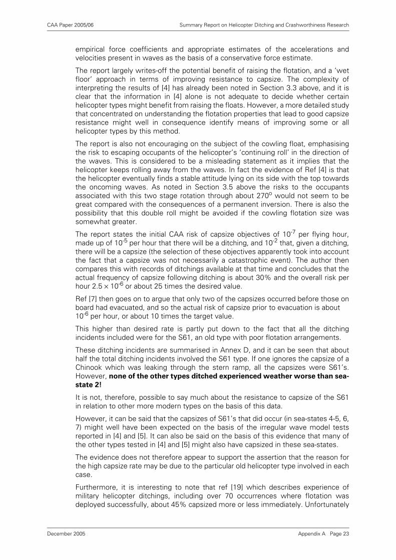
CAA Paper 2005/06 Summary Report on Helicopter Ditching and Crashworthiness Research
empirical force coefficients and appropriate estimates of the accelerations andvelocities present in waves as the basis of a conservative force estimate.
The report largely writes-off the potential benefit of raising the flotation, and a ‘wetfloor’ approach in terms of improving resistance to capsize. The complexity ofinterpreting the results of [4] has already been noted in Section 3.3 above, and it isclear that the information in [4] alone is not adequate to decide whether certainhelicopter types might benefit from raising the floats. However, a more detailed studythat concentrated on understanding the flotation properties that lead to good capsizeresistance might well in consequence identify means of improving some or allhelicopter types by this method.
The report is also not encouraging on the subject of the cowling float, emphasisingthe risk to escaping occupants of the helicopter’s ‘continuing roll’ in the direction ofthe waves. This is considered to be a misleading statement as it implies that thehelicopter keeps rolling away from the waves. In fact the evidence of Ref [4] is thatthe helicopter eventually finds a stable attitude lying on its side with the top towardsthe oncoming waves. As noted in Section 3.5 above the risks to the occupantsassociated with this two stage rotation through about 270o would not seem to begreat compared with the consequences of a permanent inversion. There is also thepossibility that this double roll might be avoided if the cowling flotation size wassomewhat greater.
The report states the initial CAA risk of capsize objectives of 10-7 per flying hour,made up of 10-5 per hour that there will be a ditching, and 10-2 that, given a ditching,there will be a capsize (the selection of these objectives apparently took into accountthe fact that a capsize was not necessarily a catastrophic event). The author thencompares this with records of ditchings available at that time and concludes that theactual frequency of capsize following ditching is about 30% and the overall risk perhour 2.5 × 10⁻⁶ or about 25 times the desired value.
Ref [7] then goes on to argue that only two of the capsizes occurred before those onboard had evacuated, and so the actual risk of capsize prior to evacuation is about 10-6 per hour, or about 10 times the target value.
This higher than desired rate is partly put down to the fact that all the ditchingincidents included were for the S61, an old type with poor flotation arrangements.
These ditching incidents are summarised in Annex D, and it can be seen that abouthalf the total ditching incidents involved the S61 type. If one ignores the capsize of aChinook which was leaking through the stern ramp, all the capsizes were S61’s.However, none of the other types ditched experienced weather worse than sea-
state 2!
It is not, therefore, possible to say much about the resistance to capsize of the S61in relation to other more modern types on the basis of this data.
However, it can be said that the capsizes of S61’s that did occur (in sea-states 4-5, 6,7) might well have been expected on the basis of the irregular wave model testsreported in [4] and [5]. It can also be said on the basis of this evidence that many ofthe other types tested in [4] and [5] might also have capsized in these sea-states.
The evidence does not therefore appear to support the assertion that the reason forthe high capsize rate may be due to the particular old helicopter type involved in eachcase.
Furthermore, it is interesting to note that ref [19] which describes experience ofmilitary helicopter ditchings, including over 70 occurrences where flotation wasdeployed successfully, about 45% capsized more or less immediately. Unfortunately
Appendix A Page 23December 2005
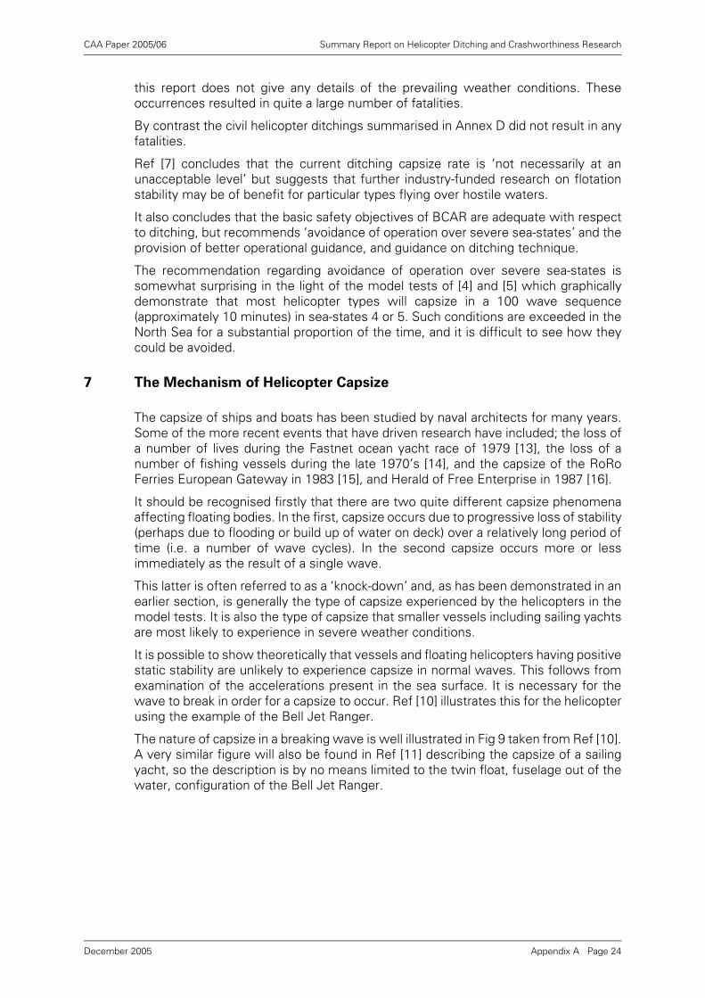
CAA Paper 2005/06 Summary Report on Helicopter Ditching and Crashworthiness Research
this report does not give any details of the prevailing weather conditions. Theseoccurrences resulted in quite a large number of fatalities.
By contrast the civil helicopter ditchings summarised in Annex D did not result in anyfatalities.
Ref [7] concludes that the current ditching capsize rate is ‘not necessarily at anunacceptable level’ but suggests that further industry-funded research on flotationstability may be of benefit for particular types flying over hostile waters.
It also concludes that the basic safety objectives of BCAR are adequate with respectto ditching, but recommends ‘avoidance of operation over severe sea-states’ and theprovision of better operational guidance, and guidance on ditching technique.
The recommendation regarding avoidance of operation over severe sea-states issomewhat surprising in the light of the model tests of [4] and [5] which graphicallydemonstrate that most helicopter types will capsize in a 100 wave sequence(approximately 10 minutes) in sea-states 4 or 5. Such conditions are exceeded in theNorth Sea for a substantial proportion of the time, and it is difficult to see how theycould be avoided.
7 The Mechanism of Helicopter Capsize
The capsize of ships and boats has been studied by naval architects for many years.Some of the more recent events that have driven research have included; the loss ofa number of lives during the Fastnet ocean yacht race of 1979 [13], the loss of anumber of fishing vessels during the late 1970’s [14], and the capsize of the RoRoFerries European Gateway in 1983 [15], and Herald of Free Enterprise in 1987 [16].
It should be recognised firstly that there are two quite different capsize phenomenaaffecting floating bodies. In the first, capsize occurs due to progressive loss of stability(perhaps due to flooding or build up of water on deck) over a relatively long period oftime (i.e. a number of wave cycles). In the second capsize occurs more or lessimmediately as the result of a single wave.
This latter is often referred to as a ‘knock-down’ and, as has been demonstrated in anearlier section, is generally the type of capsize experienced by the helicopters in themodel tests. It is also the type of capsize that smaller vessels including sailing yachtsare most likely to experience in severe weather conditions.
It is possible to show theoretically that vessels and floating helicopters having positivestatic stability are unlikely to experience capsize in normal waves. This follows fromexamination of the accelerations present in the sea surface. It is necessary for thewave to break in order for a capsize to occur. Ref [10] illustrates this for the helicopterusing the example of the Bell Jet Ranger.
The nature of capsize in a breaking wave is well illustrated in Fig 9 taken from Ref [10].A very similar figure will also be found in Ref [11] describing the capsize of a sailingyacht, so the description is by no means limited to the twin float, fuselage out of thewater, configuration of the Bell Jet Ranger.
Appendix A Page 24December 2005
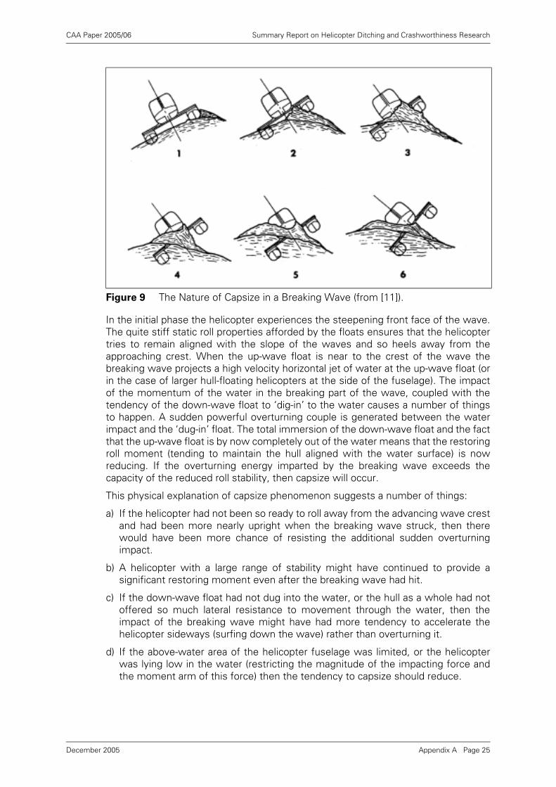
CAA Paper 2005/06 Summary Report on Helicopter Ditching and Crashworthiness Research
In the initial phase the helicopter experiences the steepening front face of the wave.The quite stiff static roll properties afforded by the floats ensures that the helicoptertries to remain aligned with the slope of the waves and so heels away from theapproaching crest. When the up-wave float is near to the crest of the wave thebreaking wave projects a high velocity horizontal jet of water at the up-wave float (orin the case of larger hull-floating helicopters at the side of the fuselage). The impactof the momentum of the water in the breaking part of the wave, coupled with thetendency of the down-wave float to ‘dig-in’ to the water causes a number of thingsto happen. A sudden powerful overturning couple is generated between the waterimpact and the ‘dug-in’ float. The total immersion of the down-wave float and the factthat the up-wave float is by now completely out of the water means that the restoringroll moment (tending to maintain the hull aligned with the water surface) is nowreducing. If the overturning energy imparted by the breaking wave exceeds thecapacity of the reduced roll stability, then capsize will occur.
This physical explanation of capsize phenomenon suggests a number of things:
a) If the helicopter had not been so ready to roll away from the advancing wave crestand had been more nearly upright when the breaking wave struck, then therewould have been more chance of resisting the additional sudden overturningimpact.
b) A helicopter with a large range of stability might have continued to provide asignificant restoring moment even after the breaking wave had hit.
c) If the down-wave float had not dug into the water, or the hull as a whole had notoffered so much lateral resistance to movement through the water, then theimpact of the breaking wave might have had more tendency to accelerate thehelicopter sideways (surfing down the wave) rather than overturning it.
d) If the above-water area of the helicopter fuselage was limited, or the helicopterwas lying low in the water (restricting the magnitude of the impacting force andthe moment arm of this force) then the tendency to capsize should reduce.
Figure 9 The Nature of Capsize in a Breaking Wave (from [11]).
Appendix A Page 25December 2005
CAA Paper 2005/06 Summary Report on Helicopter Ditching and Crashworthiness Research
From this we can deduce that:
• Helicopters with high roll inertia compared with their static roll stiffness are lesslikely to be quick to roll away from the advancing wave front and will benefit fromeffect (a) above. Their roll motion will have a greater phase lag.
• Helicopters with hull/float configurations which tend to remain on the surface ofthe water and not dig-in and present large lateral areas will benefit from (c) above.
• Helicopters which are low in the water and present a smaller and lower area forthe breaking wave to impact on will benefit from (d) above.
Incidentally, there is obviously a conflict between (c) and (d) as, for a given helicopter,in decreasing the above water area we must increase the below water area and viceversa.
Roll inertia is seen to be a major factor in the resistance of sailing yachts to capsize,and a yacht that has been dismasted is much more likely to capsize [11]. The mastrepresents a major part of the roll inertia of a yacht.
The helicopter rotor must similarly be a significant contribution to the roll inertia of ahelicopter, particularly whilst it is still rotating, when gyroscopic effects should alsohelp. There could also be a significant effect depending on where the blades stop interms of the roll inertia. A helicopter which loses blades due to contact with thewaves during the ditching will probably be more at risk of capsize than one whichmaintains the rotor intact.
We can therefore summarise the expected beneficial qualities of the helicopter whilstfloating as follows:
• high roll inertia;
• large range of static stability;
• large angle of peak righting moment;
• low lateral resistance to movement through the water;
• low above water profile.
Ref [11] identifies the importance of the ratio of roll gyradius divided by beam in thecapsize process, and plots this ratio against wave height divided by beam. On thebasis of model tests on yachts, a boundary is defined between capsize and fully stableconditions.
For comparison purposes the data from the helicopter tests in irregular waves hasbeen plotted in a similar manner in Figures 10 and 11 (for cases with and without windrespectively).
One can see immediately from these plots that the ratio of roll gyradius/beamgenerally expected for yachts is more than twice the values seen on the helicoptersconsidered in this report.
However, there seems to be some general consistency between the boundaryplotted for the yachts and the capsize boundary for the helicopters, particularly in theabsence of wind. It has been noted earlier that the main effect of the wind is to keepthe helicopter nose into the wind and waves, and thus to reduce the tendency tocapsize. The yacht model tests were performed without any wind and so moreattention should be concentrated on Fig 11.
Appendix A Page 26December 2005
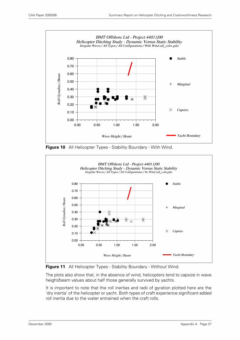
CAA Paper 2005/06 Summary Report on Helicopter Ditching and Crashworthiness Research
The plots also show that, in the absence of wind, helicopters tend to capsize in waveheight/beam values about half those generally survived by yachts.
It is important to note that the roll inertias and radii of gyration plotted here are the‘dry inertia’ of the helicopter or yacht. Both types of craft experience significant addedroll inertia due to the water entrained when the craft rolls.
Figure 10 All Helicopter Types - Stability Boundary - With Wind.
Figure 11 All Helicopter Types - Stability Boundary - Without Wind.
Appendix A Page 27December 2005
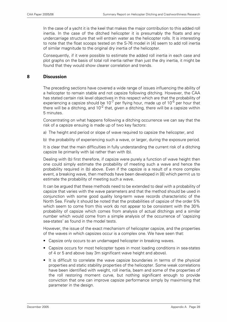
CAA Paper 2005/06 Summary Report on Helicopter Ditching and Crashworthiness Research
In the case of a yacht it is the keel that makes the major contribution to this added rollinertia. In the case of the ditched helicopter it is presumably the floats and anyundercarriage structure that will entrain water as the helicopter rolls. It is interestingto note that the float scoops tested on the S-76 model in [4] seem to add roll inertiaof similar magnitude to the original dry inertia of the helicopter.
Consequently, if it were possible to estimate the added roll inertia in each case andplot graphs on the basis of total roll inertia rather than just the dry inertia, it might befound that they would show clearer correlation and trends.
8 Discussion
The preceding sections have covered a wide range of issues influencing the ability ofa helicopter to remain stable and not capsize following ditching. However, the CAAhas stated certain risk level objectives in this respect which are that the probability ofexperiencing a capsize should be 10-7 per flying hour, made up of 10-5 per hour thatthere will be a ditching, and 10-2 that, given a ditching, there will be a capsize within5 minutes.
Concentrating on what happens following a ditching occurrence we can say that therisk of a capsize ensuing is made up of two key factors:
a) The height and period or slope of wave required to capsize the helicopter, and
b) the probability of experiencing such a wave, or larger, during the exposure period.
It is clear that the main difficulties in fully understanding the current risk of a ditchingcapsize lie primarily with (a) rather than with (b).
Dealing with (b) first therefore, if capsize were purely a function of wave height thenone could simply estimate the probability of meeting such a wave and hence theprobability required in (b) above. Even if the capsize is a result of a more complexevent, a breaking wave, then methods have been developed in [8] which permit us toestimate the probability of meeting such a wave.
It can be argued that these methods need to be extended to deal with a probability ofcapsize that varies with the wave parameters and that the method should be used inconjunction with some good quality long-term wave records characteristic of theNorth Sea. Finally it should be noted that the probabilities of capsize of the order 5%which seem to come from this work do not appear to be consistent with the 30%probability of capsize which comes from analysis of actual ditchings and a similarnumber which would come from a simple analysis of the occurrence of ‘capsizingsea-states’ as found in the model tests.
However, the issue of the exact mechanism of helicopter capsize, and the propertiesof the waves in which capsizes occur is a complex one. We have seen that:
• Capsize only occurs to an undamaged helicopter in breaking waves.
• Capsize occurs for most helicopter types in most loading conditions in sea-statesof 4 or 5 and above (say 3m significant wave height and above).
• It is difficult to correlate the wave capsize boundaries in terms of the physicalproperties and static stability properties of the helicopter. Some weak correlationshave been identified with weight, roll inertia, beam and some of the properties ofthe roll restoring moment curve, but nothing significant enough to provideconviction that one can improve capsize performance simply by maximising thatparameter in the design.
Appendix A Page 28December 2005
CAA Paper 2005/06 Summary Report on Helicopter Ditching and Crashworthiness Research
• The results of the regular wave tests and irregular wave tests do not generallyappear consistent, with one correlating with wave height and the other with waveslope (the lack of correlation with wave slope in irregular waves may be due to theabsence of a slope parameter that properly characterises the steeper waves in theirregular spectrum).
The BCAR certification requirements [20] for on-water stability refer to the steepnessof a regular wave that the helicopter must remain stable in, but also requires thatflotation and trim should be investigated in sea-states up to 6. It is clear from themodel test results given in [4] and [5] that the helicopters generally have little difficultyin satisfying the regular wave steepness criteria. It is also clear that none of themremain stable in irregular waves of sea-state 6.
Even if it is not possible on the basis of the information in [4] and [5] to be confidentabout which design parameters make the difference between a good helicopter anda poor one, it is possible to draw certain conclusions about some of the helicoptermodifications tried in these tests.
The addition of scoops to the flotation seems to be beneficial in all cases.Interestingly, the addition of scoops always increases the peak restoring moment onthe stability curve, and the range of stability. If it is this effect on static stability whichis causing the benefit in terms of resistance to capsize, then it is surprising that oneor both of these parameters does not come out more strongly as a correlator withcapsize performance. The fact that these static properties don't correlate strongly inthis way is circumstantial evidence supporting the theory that it is the dynamic effectscaused by the scoops, enhancing roll added inertia and adding extra roll damping, thatare a major reason for the benefit.
Unfortunately work on the development of practical scoops seems to have haltedbecause of difficulty in estimating the additional flotation anchor loads. The theoreticalsimulation work intended to resolve this issue was flawed, but it should be possibleto make reasonable and conservative estimates of maximum loads using empiricaldrag and inertia coefficients.
The work on raising the flotation (‘wet floor’) has been much more difficult tointerpret. Raising the floats can cause quite different effects on the static stabilityproperties of different helicopters and on the same helicopter at different weights. Aswe are not sure which properties of the static stability curve we are trying tomaximise it is difficult to know how to position the floats to the best advantage. It isnot surprising, therefore, that the model tests on helicopters with raised floatsresulted in very mixed performance.
One model test investigated the possibility of using engine cowl flotation in order toprovide a more stable side-floating attitude. The BHC and CAA comments on theresults of this experiment seem unduly harsh in terms of the risks to the escapingoccupants, and it is considered that this idea should be developed further as it doesoffer the prospect of a stable floating attitude with a helicopter escape hatchremaining above the water surface. Without a device of this sort the fundamentallytop-heavy configuration of a helicopter means that there will always be a wave highenough or steep enough to capsize it into a fully inverted attitude.
Consideration of the mechanism of capsize in a breaking wave tends to lead one awayfrom the premise that prevention of capsize lies entirely in the static stability curve,and the lack of strong correlation of model test results with the properties of thiscurve tends to confirm that the answer, if answer there is, must lie elsewhere. Workon the ‘knock-down’ capsize of sailing yachts has pointed to the importance of the rollinertia, and whilst we cannot ask the helicopter designer to change this physical
Appendix A Page 29December 2005
CAA Paper 2005/06 Summary Report on Helicopter Ditching and Crashworthiness Research
property (he has little control over it anyway), we can look at ways of increasing theadded inertia in waves. The flotation scoops are one way of doing this.
9 References
[1] CAA Letter Ref 10MG/13/5 dated 1/10/92.
[2] BMT Proposal Q94004, Review of Helicopter Ditching Performance, dated 6thOctober 1992.
[3] CAA Contract No. 7D/S/1096 dated 16th December 1992.
[4] BHC Draft Report No X/O/3282, Nov 1985, Study of Float Positioning.
[5] BHC Report No X/O/3257, April 1986, Study of Fitting Scoops to EmergencyFloats.
[6] WHL Report WER 143-20-00816, April 1986, Feasibility of Fitting Scoops.
[7] CAA-SRG Internal Report ref 9/31/R50-11C-3, Sept 1989, Helicopter DitchingSurvival Aspects.
[8] Carter, D.J.T., Brice, A.A., On Estimating the Probability that a DitchedHelicopter will be Capsized by Wave Action, IOS Report to CAA, Jan 1987.
[9] Williams, D.L., Helicopter Ditching - Assessment of Wave Data, Report DW/CAA/02, March 1991.
[10] Kidwell, J.C., Crago, W.A., Model Testing to Establish Ditching and FlotationStability Characteristics of Helicopters, American Helicopter Society, 26thAnnual National Forum, Washington DC, June 1970.
[11] Marchaj, C.A., Seaworthiness - The Forgotten Factor, Adlard Coles Ltd., 1986.
[12] Rainey, R.C.T., Thompson, J.M.T., The Transient Capsize Diagram - a Route toSoundly-based New Stability Regulations, STAB 90, Stability of Ships and OceanVehicles; 4th International Conference 24-28 Sept 1990, Naples.
[13] The Fifth Chesapeak Sailing Yacht Symposium, January 1981, Society of NavalArchitects and Marine Engineers.
[14] Morrall, A., Capsizing of Small Trawlers Royal Institution of Naval Architects,London 1979.
[15] Spouge, J., The Technical Investigation of the Sinking of the Ro-ro FerryEuropean Gateway, Trans, RINA, vol. 128, 1986.
[16] Dand, I.W., Hydrodynamic Aspects of the Sinking of the Ferry Herald of FreeEnterprise, Trans RINA, vol. 131, 1989.
[17] A Proposal for the Prediction of Dynamic Stability by Computer Analysis, BritishHovercraft Corporation, Report TF/3439, Feb 1986.
[18] Roll Characteristics of an H-3 Helicopter in Calm Water and Random Seas withSeveral Configurations of Emergency Floats Installed, David Taylor Model Basin,1980.
[19] Reader, D.C., Helicopter Ditchings - British Military Experience 1972-88, RAFInstitute of Aviation Medicine Report No. 677, March 1990.
[20] Civil Aviation Authority, BCAR Paper No. G779, 7th October 1985.
Appendix A Page 30December 2005
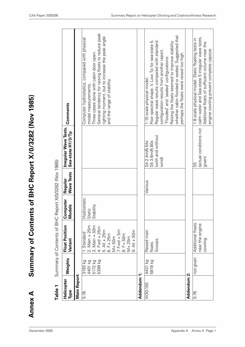
CAA Paper 2005/06 Summary Report on Helicopter Ditching and Crashworthiness Research
An
ne
x A
Su
mm
ary
of
Co
nte
nts
of
BH
C R
ep
ort
X/0
/32
82
(N
ov
19
85
)
Ta
ble
1S
umm
ary
of C
onte
nts
of B
HC
Rep
ort
X/0
/328
2 (N
ov 1
985)
Heli
co
pte
r
Ty
pe
We
igh
tsF
loat
Po
sit
ion
Vari
an
t
Co
mp
ute
r
Mo
de
ls
Reg
ula
r
Wave
Te
sts
Irre
gu
lar
Wave T
ests
.
Se
a-s
tate
H1
/3/T
pC
om
me
nts
Main
Rep
ort
:
S-7
631
93 k
g44
01 k
g51
72 k
g53
99 k
g
1. S
tand
ard
2. M
ain
+.2
5m3.
Mai
n +
.50m
4. F
wd
+.2
5m5.
All
+.2
5m6.
F+
.25m
M
+.5
0m7.
Fw
d +
.5m
8. F
+.5
0m
M+
.25m
9. A
ll +
.50m
Hyd
rost
atic
Sta
tic
Sta
bilit
y
Com
pute
r hy
dros
tatic
s, c
ompa
red
with
phy
sica
l m
odel
mea
sure
men
ts.
Thre
e ca
ses
done
with
cab
in d
oor
open
.G
ener
al t
ende
ncy
for
rais
ing
float
s to
red
uce
peak
rig
htin
g m
omen
t, b
ut t
o in
crea
se t
he p
eak
angl
e an
d th
e ra
nge
of s
tabi
lity.
Ad
den
du
m 1
:
W30
-100
4431
kg
5818
kg
Rai
sed
mai
n flo
ats.
Sco
ops.
Vario
usS
4 2.
4m/6
.54s
S5
3.6m
/6.8
0s(w
ith a
nd w
ithou
t w
ind)
1:10
sca
le p
hysi
cal m
odel
. Po
or s
pect
ral s
hape
. V. L
ow T
p fo
r se
a-st
ate
5.
Reg
ular
wav
e re
sults
com
pare
d w
ith s
tand
ard
conf
igur
atio
n re
sults
fro
m a
noth
er r
epor
t.'F
lood
ed' a
nd 's
eale
d' c
onfig
urat
ions
.R
aisi
ng t
he f
loat
s se
emed
to
impr
ove
stab
ility
w
heth
er c
abin
flo
oded
or
seal
ed. S
ugge
sted
tha
t pe
rhap
s th
e flo
ats
wer
e ra
ised
too
hig
h.
Ad
den
du
m 2
:
S-7
6no
t gi
ven
Add
ition
al f
loat
s ne
ar t
he e
ngin
e co
wlin
g.
S5
(act
ual c
ondi
tions
not
gi
ven)
1:8
scal
e ph
ysic
al m
odel
. Sta
tic f
loat
ing
test
s in
ca
lm w
ater
and
Sea
-sta
te 5
irre
gula
r w
ave
test
s.A
dditi
onal
flo
ats
of s
uffic
ient
vol
ume
near
the
en
gine
cow
ling
prev
ent
com
plet
e ca
psiz
e.
Appendix A Annex A Page 1December 2005
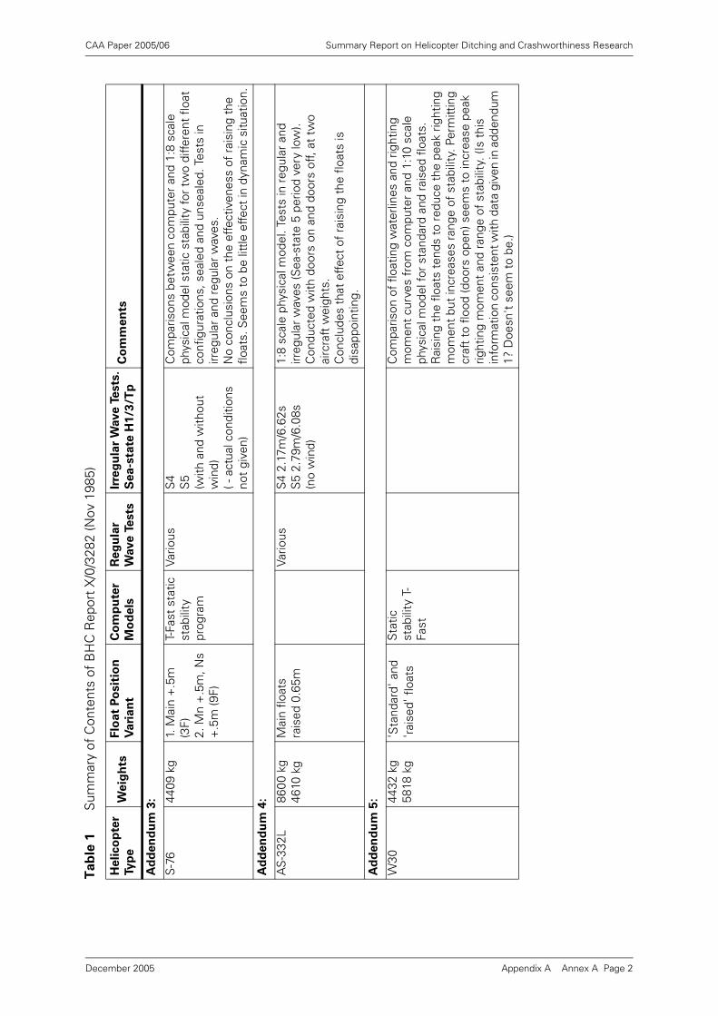
CAA Paper 2005/06 Summary Report on Helicopter Ditching and Crashworthiness Research
Ad
den
du
m 3
:
S-7
644
09 k
g1.
Mai
n +
.5m
(3
F)2.
Mn
+.5
m, N
s +
.5m
(9F)
T-Fa
st s
tatic
st
abili
ty
prog
ram
Vario
usS
4S
5(w
ith a
nd w
ithou
t w
ind)
( - a
ctua
l con
ditio
ns
not
give
n)
Com
paris
ons
betw
een
com
pute
r an
d 1:
8 sc
ale
phys
ical
mod
el s
tatic
sta
bilit
y fo
r tw
o di
ffere
nt f
loat
co
nfig
urat
ions
, sea
led
and
unse
aled
. Tes
ts in
irr
egul
ar a
nd r
egul
ar w
aves
.N
o co
nclu
sion
s on
the
effe
ctiv
enes
s of
rai
sing
the
flo
ats.
See
ms
to b
e lit
tle e
ffect
in d
ynam
ic s
ituat
ion.
Ad
den
du
m 4
:
AS
-332
L86
00 k
g46
10 k
gM
ain
float
s ra
ised
0.6
5mVa
rious
S4
2.17
m/6
.62s
S5
2.79
m/6
.08s
(no
win
d)
1:8
scal
e ph
ysic
al m
odel
. Tes
ts in
reg
ular
and
irr
egul
ar w
aves
(Sea
-sta
te 5
per
iod
very
low
). C
ondu
cted
with
doo
rs o
n an
d do
ors
off,
at t
wo
airc
raft
wei
ghts
.C
oncl
udes
tha
t ef
fect
of
rais
ing
the
float
s is
di
sapp
oint
ing.
Ad
den
du
m 5
:
W30
4432
kg
5818
kg
'Sta
ndar
d' a
nd
'rais
ed' f
loat
sS
tatic
st
abili
ty T
-Fa
st
Com
paris
on o
f flo
atin
g w
ater
lines
and
rig
htin
g m
omen
t cu
rves
fro
m c
ompu
ter
and
1:10
sca
le
phys
ical
mod
el fo
r st
anda
rd a
nd r
aise
d flo
ats.
R
aisi
ng t
he f
loat
s te
nds
to r
educ
e th
e pe
ak r
ight
ing
mom
ent
but
incr
ease
s ra
nge
of s
tabi
lity.
Per
mitt
ing
craf
t to
flo
od (d
oors
ope
n) s
eem
s to
incr
ease
pea
k rig
htin
g m
omen
t an
d ra
nge
of s
tabi
lity.
(Is
this
in
form
atio
n co
nsis
tent
with
dat
a gi
ven
in a
dden
dum
1?
Doe
sn't
see
m t
o be
.)
Ta
ble
1S
umm
ary
of C
onte
nts
of B
HC
Rep
ort
X/0
/328
2 (N
ov 1
985)
Heli
co
pte
r
Ty
pe
We
igh
tsF
loat
Po
sit
ion
Vari
an
t
Co
mp
ute
r
Mo
de
ls
Reg
ula
r
Wave
Te
sts
Irre
gu
lar
Wave T
ests
.
Se
a-s
tate
H1
/3/T
pC
om
me
nts
Appendix A Annex A Page 2December 2005
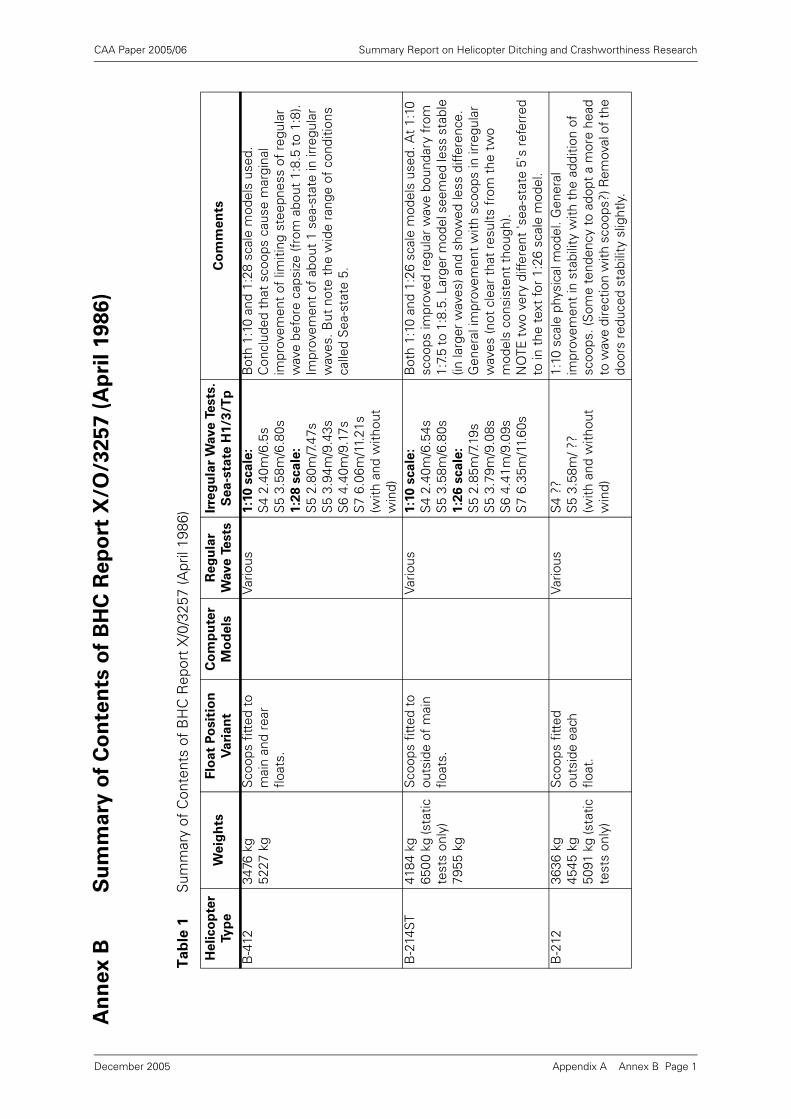
CAA Paper 2005/06 Summary Report on Helicopter Ditching and Crashworthiness Research
An
ne
x B
Su
mm
ary
of
Co
nte
nts
of
BH
C R
ep
ort
X/O
/32
57
(A
pri
l 1
98
6)
Ta
ble
1S
umm
ary
of C
onte
nts
of B
HC
Rep
ort
X/0
/325
7 (A
pril
1986
)
He
lico
pte
r
Ty
pe
We
igh
tsF
loat
Po
sit
ion
Va
ria
nt
Co
mp
ute
r
Mo
de
ls
Re
gu
lar
Wave T
ests
Irre
gu
lar
Wave T
ests
.
Sea
-sta
te H
1/3
/Tp
Co
mm
en
ts
B-4
1234
76 k
g52
27 k
gS
coop
s fit
ted
to
mai
n an
d re
ar
float
s.
Vario
us1:1
0 s
ca
le:
S4
2.40
m/6
.5s
S5
3.58
m/6
.80s
1:2
8 s
ca
le:
S5
2.80
m/7
.47s
S5
3.94
m/9
.43s
S6
4.40
m/9
.17s
S7
6.06
m/1
1.21
s(w
ith a
nd w
ithou
t w
ind)
Bot
h 1:
10 a
nd 1
:28
scal
e m
odel
s us
ed.
Con
clud
ed t
hat
scoo
ps c
ause
mar
gina
l im
prov
emen
t of
lim
iting
ste
epne
ss o
f re
gula
r w
ave
befo
re c
apsi
ze (f
rom
abo
ut 1
:8.5
to
1:8)
.Im
prov
emen
t of
abo
ut 1
sea
-sta
te in
irre
gula
r w
aves
. But
not
e th
e w
ide
rang
e of
con
ditio
ns
calle
d S
ea-s
tate
5.
B-2
14ST
4184
kg
6500
kg
(sta
tic
test
s on
ly)
7955
kg
Sco
ops
fitte
d to
ou
tsid
e of
mai
n flo
ats.
Vario
us1:1
0 s
ca
le:
S4
2.40
m/6
.54s
S5
3.58
m/6
.80s
1:2
6 s
ca
le:
S5
2.85
m/7
.19s
S5
3.79
m/9
.08s
S6
4.41
m/9
.09s
S7
6.35
m/1
1.60
s
Bot
h 1:
10 a
nd 1
:26
scal
e m
odel
s us
ed. A
t 1:
10
scoo
ps im
prov
ed r
egul
ar w
ave
boun
dary
fro
m
1:7.
5 to
1:8
.5. L
arge
r mod
el s
eem
ed le
ss s
tabl
e (in
larg
er w
aves
) and
sho
wed
less
diff
eren
ce.
Gen
eral
impr
ovem
ent
with
sco
ops
in ir
regu
lar
wav
es (n
ot c
lear
tha
t re
sults
fro
m t
he t
wo
mod
els
cons
iste
nt t
houg
h).
NO
TE t
wo
very
diff
eren
t 'se
a-st
ate
5's
refe
rred
to
in t
he t
ext
for
1:26
sca
le m
odel
.B
-212
3636
kg
4545
kg
5091
kg
(sta
tic
test
s on
ly)
Sco
ops
fitte
d ou
tsid
e ea
ch
float
.
Vario
usS
4 ??
S5
3.58
m/ ?
?(w
ith a
nd w
ithou
t w
ind)
1:10
sca
le p
hysi
cal m
odel
. Gen
eral
im
prov
emen
t in
sta
bilit
y w
ith t
he a
dditi
on o
f sc
oops
. (S
ome
tend
ency
to a
dopt
a m
ore
head
to
wav
e di
rect
ion
with
sco
ops?
) Rem
oval
of t
he
door
s re
duce
d st
abili
ty s
light
ly.
Appendix A Annex B Page 1December 2005
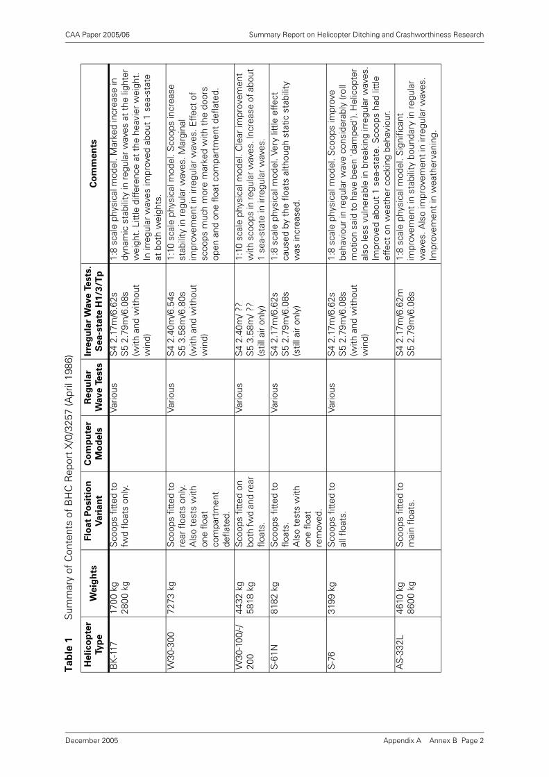
CAA Paper 2005/06 Summary Report on Helicopter Ditching and Crashworthiness Research
BK
-117
1700
kg
2800
kg
Sco
ops
fitte
d to
fw
d flo
ats
only
.Va
rious
S4
2.17
m/6
.62s
S5
2.79
m/6
.08s
(with
and
with
out
win
d)
1:8
scal
e ph
ysic
al m
odel
. Mar
ked
incr
ease
in
dyna
mic
sta
bilit
y in
regu
lar
wav
es a
t th
e lig
hter
w
eigh
t. L
ittle
diff
eren
ce a
t th
e he
avie
r w
eigh
t.
In ir
regu
lar
wav
es im
prov
ed a
bout
1 s
ea-s
tate
at
bot
h w
eigh
ts.
W30
-300
7273
kg
Sco
ops
fitte
d to
re
ar f
loat
s on
ly.
Als
o te
sts
with
on
e flo
at
com
part
men
t de
flate
d.
Vario
usS
4 2.
40m
/6.5
4sS
5 3.
58m
/6.8
0s(w
ith a
nd w
ithou
t w
ind)
1:10
sca
le p
hysi
cal m
odel
. Sco
ops
incr
ease
st
abili
ty in
reg
ular
wav
es. M
argi
nal
impr
ovem
ent
in ir
regu
lar
wav
es. E
ffect
of
scoo
ps m
uch
mor
e m
arke
d w
ith t
he d
oors
op
en a
nd o
ne f
loat
com
part
men
t de
flate
d.
W30
-100
/-/20
044
32 k
g58
18 k
gS
coop
s fit
ted
on
both
fwd
and
rear
flo
ats.
Vario
usS
4 2.
40m
/ ??
S5
3.58
m/ ?
?(s
till a
ir on
ly)
1:10
sca
le p
hysi
cal m
odel
. Cle
ar im
prov
emen
t w
ith s
coop
s in
regu
lar w
aves
. Inc
reas
e of
abo
ut
1 se
a-st
ate
in ir
regu
lar
wav
es.
S-6
1N81
82 k
gS
coop
s fit
ted
to
float
s.A
lso
test
s w
ith
one
float
re
mov
ed.
Vario
usS
4 2.
17m
/6.6
2sS
5 2.
79m
/6.0
8s(s
till a
ir on
ly)
1:8
scal
e ph
ysic
al m
odel
. Ver
y lit
tle e
ffect
ca
used
by
the
float
s al
thou
gh s
tatic
sta
bilit
y w
as in
crea
sed.
S-7
631
99 k
gS
coop
s fit
ted
to
all f
loat
s.Va
rious
S4
2.17
m/6
.62s
S5
2.79
m/6
.08s
(with
and
with
out
win
d)
1:8
scal
e ph
ysic
al m
odel
. Sco
ops
impr
ove
beha
viou
r in
reg
ular
wav
e co
nsid
erab
ly (r
oll
mot
ion
said
to h
ave
been
'dam
ped'
). H
elic
opte
r al
so le
ss v
ulne
rabl
e in
bre
akin
g irr
egul
ar w
aves
.Im
prov
ed a
bout
1 s
ea-s
tate
. Sco
ops
had
little
ef
fect
on
wea
ther
coc
king
beh
avio
ur.
AS
-332
L46
10 k
g86
00 k
gS
coop
s fit
ted
to
mai
n flo
ats.
S4
2.17
m/6
.62m
S5
2.79
m/6
.08s
1:8
scal
e ph
ysic
al m
odel
. Sig
nific
ant
impr
ovem
ent
in s
tabi
lity
boun
dary
in r
egul
ar
wav
es. A
lso
impr
ovem
ent
in ir
regu
lar
wav
es.
Impr
ovem
ent
in w
eath
erva
ning
.
Ta
ble
1S
umm
ary
of C
onte
nts
of B
HC
Rep
ort
X/0
/325
7 (A
pril
1986
)
He
lico
pte
r
Ty
pe
We
igh
tsF
loat
Po
sit
ion
Va
ria
nt
Co
mp
ute
r
Mo
de
ls
Re
gu
lar
Wave T
ests
Irre
gu
lar
Wave T
ests
.
Sea
-sta
te H
1/3
/Tp
Co
mm
en
ts
Appendix A Annex B Page 2December 2005
CAA Paper 2005/06 Summary Report on Helicopter Ditching and Crashworthiness Research
General notes on the tests
a) Very poor representation of the irregular spectrum shape. In particular sea-state 5far too low period (lower than sea-state 4!). This means that sea-state 5 muchsteeper than 4 and therefore a poor test.
b) Poor quality reports, difficult to use. Number of photos missing from the draft.
c) The important effect of wind on controlling the heading of the helicopter to headinto wind (and thus into waves). Otherwise they tend to turn beam-on whichusually promotes capsize. Note that many of the tests were started at differentinitial headings (e.g. head, quartering, beam) but thereafter the helicopter was freeto choose its own heading.
d) A key issue is the presence or otherwise of breaking waves in the tests. It is oftenmentioned that capsize occurred in breaking waves, but when a helicopter doesnot capsize it is not mentioned whether there were any breaking waves present.
e) The steepness of regular waves used is such that any could be breaking in a modelbasin. Not clear which ones were and which ones were not.
f) Heavier aircraft always seem to be more stable.1
g) Much of the data is compared with results from other references which give theresults of the standard floats tests. Concern about whether the wave conditionswere the same in these tests.
h) Problems of waves based on sea-states (the definitions of which have changedfrom time-to-time).
i) Effect of scoops will be to increase static stability and increase damping and addedinertia. Not clear which effect is more important. (They could have done tests withdamping or added mass devices only.)
j) No attention to the direction of capsize? Is roll always the vulnerable axis, or dohelicopters sometimes turn across a diagonal. Not clear that the calculation andstatic stability measurement methods would have determined this.
k) What is lacking in this work is any investigation of which parameters in thehelicopter design influence the tendency to capsize. The key issues could be: thepeak righting moment, angle of peak moment, range of stability, floating trimangle, tendency to weathervane, underwater lateral area (resistance to beingpushed sideways by breaking wave), and the direction of minimum static stability.
l) No information of the probability of capsize in any irregular wave condition.
m) What is mostly lacking from these reports is clear tabular presentation of thecapsize occurrence in the different conditions tested (should be obtainable fromthe experiment book notes or from video records). It is often extremely difficult towork out from the narrative exactly which weight/wind/etc. condition is beingdescribed.
1. Note added in 2005: The helicopter's weight is correlated with the height of its centre of gravity. Greater weight implies a lower centre of gravity. See footnote on page 10 of Appendix A.
Appendix A Annex B Page 3December 2005
CAA Paper 2005/06 Summary Report on Helicopter Ditching and Crashworthiness Research
Annex C Model Tests in Regular and Irregular Waves
1 Introduction
Physical model tests are often the only way of handling complicated dynamicproblems such as the capsize of helicopters in waves. Models constructed with dueregard to the necessary physical similarity and mass/inertia properties can give arealistic qualitative and quantitative impression of the way in which the full scalehelicopter will behave. The tests can be particularly impressive to the layman whosees what appears to be a true representation of reality (particularly when filmed, andslowed down to simulated `real-time').
However, such tests do present a number of real difficulties which must beconsidered when such tests are designed or the results from them interpreted.
The main difficulties when considered in the context of helicopters are:
• The construction of accurate models (accurate in terms of shape, floodability,mass, inertia, etc.)
• The generation of appropriate and repeatable wave conditions.
• The conduct of tests in these waves in a controlled and repeatable manner.
2 Model Construction
It is important that models used in this type of testing are statically and dynamicallysimilar to the full scale helicopter.
Static similarity involves ensuring that the external shape and dimensions areaccurately represented on the model. When the model is going to be permitted toflood through open doors it is also necessary to ensure that the internal voids areproperly modelled. This latter can be quite difficult to do precisely owing to the needfor very thin walls, and the many internal details (passenger seats etc.).
The model must also have the correct weight and centre of gravity location. This canbe quite difficult to arrange (particularly for small models when it is sometimesdifficult to make the model light enough). Obtaining the appropriate centre of gravitylocation involves balancing the model and adding ballast weights until the correct CGlocation is achieved.
Dynamic similarity involves ensuring that the inertia of the models in the threerotational axes is correct. The most important in the context of capsize is obviouslythe roll inertia or radius of gyration.
It is usual in wave model test reports to list all the static and dynamic properties ofthe model both as 'desired' and 'obtained' so that the reader can judge the accuracyof the modelling. In the case of the BHC model test reports [4] and [5], information onthe means of balancing the model and achieving the desired properties is rathersketchy, and tables showing full scale and model properties do not seem to be 'asmeasured' properties of the model, but rather just desired values scaled down fromfull scale.
Appendix A Annex C Page 1December 2005

CAA Paper 2005/06 Summary Report on Helicopter Ditching and Crashworthiness Research
In the context of helicopters there are some specific modelling problems:
• How to model the interior spaces when water is permitted to flood in and washthrough the cabin.
• How to model the rotor. The prototype rotor assemblies are quite flexible, and it isnot immediately clear how the inertia of the rotor influences the total inertia of thehelicopter at wave frequencies. The rotor tips are also likely to touch the watersurface in extreme conditions and it is not clear how this should be modelled. (It isnoticeable that most of the helicopter models tested by BHC did not have rotorsfitted, but in some cases a mast with a weight on the top was used to help obtainthe required total CG and inertias.)
3 Wave Conditions
3.1 Regular Waves
'Regular' waves (the reason for the quote marks will become apparent later) areintended to be regular in terms of the wave amplitude and frequency, the wavemakerpaddle normally moving with a sinusoidal movement.
Until the late 60's almost all wave model tests were performed in regular wavesbecause this was the only wave generation technology available. All realised thatthese regular waves were a very poor model of the real waves experienced in theocean, but if one was able to assume linearity of response, harmonic or Fourieranalysis provided ways of interpreting this information to predict the behaviour inirregular seas.
In addition to not being representative of real ocean waves the apparent simplicity ofsinusoidal regular waves is, to some extent, illusory. Only the least steep (small waveheight compared with wave length) approximate to sinusoidal shape. The steeperthese waves become, the less sinusoidal they are - the peaks get more sharp and thetroughs flatten. Somewhere between a wave length/wave height of 10 - 7 thesewaves also break.
In longer model basins it also becomes apparent that such 'regular' waves do notpropagate unchanged down the tank. Depending on their steepness, and the distancethey have travelled, and the purity of the initial wave form, these waves degrade andchange shape as they propagate. Eventually they become quite irregular and break.This means that the shape and properties of the wave are different in different partsof the tank, and also tend to change with time as reflections and other 'noise' build-up in the tank accelerate the degradation process.
Furthermore, waves steeper than 1:10 will often break as they are generated at thewavemaker paddle.
Once breaking is occurring in a 'regular' wave train, an energy conversion process isoccurring that ensures that the wave cannot continue to propagate with the sameshape and regular properties. It can no longer be a regular wave.
It is clear from the above that tests performed in steep regular waves are fraught withdifficulties. The wave shape changes with position in the tank and with elapsed time,and one run will usually be different from the next. This presents particular problemsfor the testing of a free-drifting model as the helicopter model will tend to drift downthe tank from a region of smooth regular waves into a region of steadily increasingirregularity and wave breaking. (The model cannot be constrained to remain in thesame place, as these constraining forces would have a major effect on its behaviour.)
Appendix A Annex C Page 2December 2005
CAA Paper 2005/06 Summary Report on Helicopter Ditching and Crashworthiness Research
These factors were well-understood by those who performed the helicopter modeltests in steep 'regular' waves. It is clear from the work reported that no capsizesoccur unless the vehicle is hit by a breaking wave. Thus 'regular' waves in this contexthave really been used as a way of making breaking waves - which are inevitablyirregular by nature.
It is understood that the wave height, wavelength and steepness were estimated asbest as possible for an individual wave that capsized (or failed to capsize) the model.This was in itself very difficult in practice as the model was not necessarily alongsidea wave probe at the moment of interest.
3.2 Irregular Waves
The use of 'more realistic' irregular waves has been on the increase since the 60's.Understanding of the ocean environment was improving, and later the availability ofcheap computer technology and servo-controlled wavemakers started to impact onthe science, and permitted more sophisticated control of wavemakers.
Early irregular wavemakers were electro-mechanical, driven by a variable speedelectric motor via an eccentric crank, where the speed of the motor was controlled bysome kind of programming device (often a punched card). In these systems theirregular sequence was usually quite short (say 100 waves) before the programrepeated, and this type of control made it difficult to produce waves with a spectrumshape and Gaussian randomness (or pseudo-randomness) that was representative ofthe real ocean.
Later wavemakers, actuated by hydraulic servo systems or linear electrical actuatorsand controlled by computer, solved these problems and made it possible to generatemore or less infinite sequences of pseudo-random waves with the desired spectraland statistical properties. More recently this technology has been extended to multi-directional irregular waves in some tanks.
A good quality irregular wavemaker makes it possible to generate irregular waves ina closely controlled and repeatable fashion that is a good representation of a givensea-state. In fact wavemaker technology today is capable of generating waves tomuch closer tolerances than the ocean environment is generally understood.
The strategy adopted in the irregular wave test is rather different from a that used ina regular wave test. The usual policy is to set a given sea-state (usually defined interms of a significant wave height, mean period and spectrum shape) and record thebehaviour of the vessel under test for a long period of time (often about 3 hoursprototype time). The reason for the long run times is that the results of the test canonly really be interpreted properly in a statistical fashion if there are a lot of waves. Inprinciple, a helicopter ditching test could be run on many occasions in different time-history realisations of the same sea-state, and an accurate determination made of theprobability of capsize in any period of time. In practice there are some difficulties withthis approach.
The free drifting nature of the model means that eventually the model will drift downthe tank and the run must be stopped. Also when capsize occurs, the test mustobviously be halted and the model recovered.
In addition to this inherent difficulty it is unfortunate that the model tests conductedin irregular waves described in [4] and [5] have been performed using an electro-mechanical wavemaker of the early type. This has lead to very poor spectral shapingand very short run sequences.
Appendix A Annex C Page 3December 2005
CAA Paper 2005/06 Summary Report on Helicopter Ditching and Crashworthiness Research
All that is known from such a test is whether the helicopter capsized or not. If it did,then there is still no information about the probability of capsize in a given period ofexposure. If the size of the wave that capsized the helicopter were known, then itmight be possible to calculate the probability of this wave, but this has not beenrecorded.
Similarly, if a helicopter remained upright through a sequence of 100 waves (about 10minutes prototype time) then there is nothing to say that a 101st wave would not havecapsized it. A detailed statistical analysis of the 100 wave heights experienced wouldreveal whether these 100 waves represented a typical distribution of heights, butagain this information is not believed to be available for the tests concerned.
3.3 An Ideal Helicopter Capsize Model Test
Given that the requirement for a ditched helicopter is to remain upright long enoughfor crew and passengers to make a safe evacuation to the life rafts, the realrequirement for a helicopter model test is to demonstrate that the probability ofcapsize within a given short period (say 5 minutes) is adequately low.
The only way of demonstrating this in a physical model test is to run a large series ofrealistic irregular wave conditions and record the mean frequency of capsizes thatoccur. This will enable the probability of capsize to be estimated. Alternatively, if thewave height and period characteristics which cause capsize can be recorded in eachcase (difficult because of the drifting position of the helicopter model), then theprobability of meeting this wave can be estimated and the probability of capsizearrived at in this way.
This implies that a large number of long tests must be performed in a long tank withgood wave generation properties.
Appendix A Annex C Page 4December 2005

CAA Paper 2005/06 Summary Report on Helicopter Ditching and Crashworthiness Research
Appendix A Annex D Page 1
An
ne
x D
He
lico
pte
r D
itch
ing
Occu
rre
nce
s S
um
ma
ry
Ther
e ar
e 11
ditc
hing
s lis
ted
with
4 c
lear
cap
size
s. T
his
indi
cate
s th
at t
he o
vera
ll ca
psiz
e ra
te is
abo
ut 3
6%.
The
stat
ed o
bjec
tive
in H
AR
P 1
1 an
d 9/
31/R
50-1
1C-3
is 1
% (b
ased
on
an o
vera
ll ta
rget
ris
k of
'ditc
hing
+ c
apsi
ze' o
f 10
-7 p
er h
our
and
an a
ctua
l ditc
hing
rat
e of
10-5
per
hou
r).
Ta
ble
1S
umm
ary
of H
elic
opte
r D
itchi
ng In
cide
nts
(Exc
lude
s cr
ashe
s in
to s
ea w
here
sig
nific
ant
dam
age
was
sus
tain
ed)
Sou
rces
: CA
A D
atab
ase,
plu
s P
aper
HA
RP
11
10/8
/83
Date
Ty
pe
Se
a-
sta
te
Win
d
(kn
)L
oca
tio
n
Da
ma
ge
d
on
lan
din
g?
Ca
psiz
ed
?Fa
tali
tie
s
Su
rviv
or
sC
om
me
nts
??/1
1/70
S-6
14-
5N
orth
Sea
Y3
Cap
size
d ju
st a
fter
eva
cuat
ion,
pro
babl
y du
e to
lo
ss o
f se
a an
chor
.
8/3/
76W
esse
xC
alm
Nor
th S
ea?
14A
ppea
rs t
o be
a fa
irly
unco
ntro
lled
desc
ent.
A
ircra
ft lo
st. (
Cap
size
d la
ter?
)
??/7
/76
Bo
105
1-2
No
prob
lem
s re
port
ed.
1/10
/77
S-6
17
30-4
0N
orth
Sea
Y3
Larg
e w
ave
lifte
d no
se u
p an
d to
left
. Cap
size
d in
30
s N
o tim
e to
dep
loy
sea
anch
or.
31/7
/80
S-6
10-
1N
orth
Sea
15
11/3
/83
S-6
10-
1N
orth
Sea
17N
ot d
amag
ed in
acc
iden
t, b
ut e
vent
ually
san
k as
a
resu
lt of
dam
age
caus
ed d
urin
g at
tem
pted
re
cove
ry.
2/5/
84C
hino
ok1
Nor
th S
eaY
47C
apsi
zed
afte
r ab
out
10+
min
utes
follo
win
g flo
odin
g. (L
ack
of f
lota
tion
inte
grity
.)
15/5
/84
Bel
l 214
low
Nor
th S
eaY
?20
Flot
atio
n ba
gs p
unct
ured
. Not
cle
ar w
heth
er it
ca
psiz
ed.
13/7
/88
S-6
14
Nor
th S
ea21
Suc
cess
ful d
itchi
ng a
nd e
vacu
atio
n. B
urne
d,
brok
e up
and
san
k.
10/1
1/88
S-6
15-
6N
orth
Sea
Y12
Rol
led
to th
e rig
ht a
nd c
apsi
zed
(imm
edia
tely
?) in
45
mph
win
ds.
25/4
/89
B 1
05lo
wS
CAT
STA
Y2
Rig
ht fr
ont a
nd b
oth
rear
floa
ts p
artia
lly d
etac
hed
in fo
rwar
d sp
eed
land
ing.
No
caps
ize
men
tione
d.
December 2005
CAA Paper 2005/06 Summary Report on Helicopter Ditching and Crashworthiness Research
Appendix B1 Review of Helicopter Ditching
Certification Requirements
Executive Summary
BMT Offshore Ltd. was asked by the Civil Aviation Authority to perform a review of helicopterditching performance and current certification requirements.
An earlier report [4] considered and discussed the existing information on the factorsinfluencing the on-water stability of current helicopter types. This second report in the seriesdeals with the current certification requirements for helicopters in this respect.
The current CAA requirements are mainly defined in British Civil Airworthiness RequirementBCAR Paper G779 dated 7th October 1985 [5]. This document amended the previous BCARChapter G4-10 and associated Appendix dated 20th January 1975 [6].
The study has found that the requirements of this paper are ambiguous in terms of theperformance expected in regular waves and in irregular sea-states. The paper seems to havebeen interpreted in the past to mean that the helicopter may pass one or other of the criteria,but does not have to pass both. None of the existing helicopters considered in [4] seem to passthe irregular sea-state criterion, but all seem to pass the regular wave steepness criterion.
It is considered that this ambiguity is undesirable, and the requirements should be clarified.
Furthermore it is considered that the results of regular wave tests may be misleading, and thatconsequently an irregular wave criterion is a more realistic measure of the likely actualperformance of the helicopter ditched in the ocean. It is suggested that the current reliance ondefining wave conditions using sea-state numbers should be dropped in favour of a moreprecise definition of the sea-state requirements in terms of significant wave height, period andspectrum shape. It is also suggested that a minimum model testing standard should beconsidered.
An alternative to the definition of a required performance in specified sea-states is alsodiscussed. This would instead define a maximum probability of capsize when ditched in the'operational area'. This would place more responsibility on the designer to test his helicopter tothe appropriate operational conditions. This possibility will be investigated further in the nextreport in this series.
Appendix B1 Page 1December 2005
CAA Paper 2005/06 Summary Report on Helicopter Ditching and Crashworthiness Research
1 Introduction
BMT Offshore Ltd. (BMT) was asked [1]1 by the Civil Aviation Authority (CAA) topropose a review of helicopter ditching performance. BMT responded with a proposal[2], and based on this proposal, CAA put in place a contract for the work to beperformed [3].
The review was to look critically at the various research reports and reviewdocuments that CAA had commissioned in recent years, and to summarise andcomment on their findings.
1.1 Objectives
The objectives of the overall study were stated to be [2] as follows:
a) Perform a critical review of a number of documents with the objective of drawingconclusions from this work and prepare an overview document (or documents)suitable for publication by CAA.
b) Perform a critical review of the current UK Emergency Alighting on Waterhelicopter design requirements as specified by BCAR Paper No G779 dated 7thOctober 1985 [5], and where appropriate make recommendations on how theserequirements might be improved, and whether there are better ways of assessinga helicopter's water-borne stability.2
c) Based on the results of (a) and (b) above, and the results of a separate study,review North Sea helicopter ditching performance over the past 20 years andassess the practicality of imposing a new probability-based methodology for NorthSea helicopter operations, taking account of specific type's ditching rates, capsizeprobability and operating environment.
This second report deals with the results of (b) above only.
1.2 Background
The stated objective in the certification of a helicopter in relation to ditching in the seais that the helicopter should remain upright for sufficient time for the occupants toescape (not less than 5 minutes). This implies that there should be an acceptably lowprobability of meeting a wave large enough or steep enough to capsize the helicopterin this short period of time.
The probability of experiencing a capsize is dependent on two key factors:
a) The height and period or slope of wave required to capsize the helicopter, and
b) the probability of experiencing such a wave, or larger, during the exposure period.
The first report in this series [4] studied model testing and theoretical research reportson the topic. The main conclusions of this part of the study were that the model testresults were very difficult to interpret in terms of the known physical properties of thehelicopters, but it was noted that helicopter models only seemed to capsize inbreaking waves.
1. References may be found in Section 6 on page 9.2. Note added in 2005: This report was written in 1993, at a time when all helicopters operating in the UK North Sea were
certificated according to BCAR. BCAR ditching certification requirements have since been superseded by JAR/FAR requirements 27 and 29.801. JAR requirement 29.801 was reviewed and compared with BCAR G779 in a follow-up BMT report 44035r32 dated November 1995. Both sets of requirements were found to suffer from similar ambiguities.
Appendix B1 Page 2December 2005
CAA Paper 2005/06 Summary Report on Helicopter Ditching and Crashworthiness Research
2 Conclusions and Recommendations
2.1 The current helicopter certification requirements in relation to ditching and afloatstability are ambiguous or incomplete in some respects.
2.2 The main areas of ambiguity are:
a) Whether regular waves, or irregular waves, or both, should be tested.
b) How irregular waves are to be defined in terms of steepness or spectrum shape.
c) Whether conditions more severe than sea-state 6 are intended to be considered(say in the context of northern North Sea operations) and how these should bechosen.
d) What damage the helicopter should be considered to have sustained in the courseof the ditching.
e) Exactly what results are required from the (compulsory) model tests.
2.3 It is recommended that the requirements should be amended to remove theseambiguities.
2.4 There are two clear options available in removing the ambiguities and improving thecertification requirements:
a) Include a clear specification of the wave conditions to be used in testing.
b) Remove all reference to specific sea-states and require the designer to simplydemonstrate an adequately low risk of capsize in the intended operational area.
2.5 If the approach 2.4 a) above is to be followed, it is recommended that this shouldfocus on model testing in irregular waves, and should cover:
a) A definition of the wave conditions in terms of significant wave height, period andspectrum shape required for the model tests.
b) A definition of the way in which the severity of the conditions is to be selected. Ifthere is a table of wave conditions analogous to the current requirement, then thecircumstances under which more severe (or less severe) conditions may beapplied.
c) A specification of the minimum model testing standards required (e.g. wavegeneration techniques, duration of runs, type of analysis of results etc.), and a cleardefinition of the objective of the tests (e.g. to demonstrate a probability of capsizeduring a given period of time of less than a given required value).
2.6 The use of regular wave tests against a specific wave steepness criterion should bediscouraged as, owing to the fact that capsize only normally occurs in breaking waves,the results are likely to depend more on the wave basin properties than on thehelicopter model properties.
2.7 The next report in this series will pursue the possibilities of 2.4 b) above in more detailand report on their practicability in certification terms.
Appendix B1 Page 3December 2005
CAA Paper 2005/06 Summary Report on Helicopter Ditching and Crashworthiness Research
3 BCAR Paper G779
Paper G779 issued on 7th October 1985 [5] amended Chapter G410 EmergencyAlighting on Water, and the G410 Appendix. Previously the G410 Chapter had beenissued on 20th January 1975 [6], and had therefore been in force for about 10 years.
The main changes brought in by the 1985 amendment were;
a) the reduction of the sea-state range from 0 - 7 to 0 - 6 (but no change in the 9.15mmaximum wave height),
b) the amendment of the sea-state table,
c) the introduction of a period of time for which the rotorcraft must remain stable“.. for not less than 5 minutes”,
d) the fact that a sea anchor, or similar device, “may not be assumed”, whendemonstrating compliance,
e) the fact that “more severe criteria will be applicable” in particular geographicalareas, and
f) the change to more severe “individual wave” steepness criteria.
The Paper G779 can be studied on three levels; the clarity of its meaning, the effectof this meaning in seakeeping or stability terms, and the way in which it seems tohave been interpreted in practice since 1985.
The following sections deal with these three separate issues in turn.
3.1 Clarity of Meaning / Ambiguities
In most respects the intended meaning of G779 in terms of helicopter stabilityfollowing ditching is clear:
Section 2 requires that the craft should remain afloat for the time required
for everybody to escape, and further indicates that this time should not be
less than 5 minutes in severe seas. (Note that 'severe seas' are not definedhere, but from later sections we may assume that their definition is to be foundin G4-10 Appendix which implies that a severe sea is therefore sea-state 6). Thissection also mentions that allowance for damage to the helicopter should
be made, although the nature or extent of this damage is not defined in anyway.
Section 4 requires that satisfactory flotation and trim characteristics shall bedemonstrated by investigation and model tests conducted so that theresults would be valid in the declared conditions. (Note that the conduct of amodel test is compulsory.)
Section 5.2 defines the declared conditions as those in which compliance
with the requirements have been demonstrated, and that if these are lessthan the conditions given in the Appendix (i.e. sea-states 0 - 6), then theselimitations shall be included in the flight manual. Furthermore it indicatesthat in particular geographical areas more severe criteria will be applicable.
Appendix B1 Page 4December 2005
CAA Paper 2005/06 Summary Report on Helicopter Ditching and Crashworthiness Research
The main potential ambiguity in G779 lies in the definition of the sea-state conditionsin the G410 Appendix, as follows:
Firstly these are stated to be the conditions which should be investigated. Theconcept of demonstrating compliance has been lost at this point and therequirement consequently seems much weaker. However, presumablyreference back to Section 4 makes it clear that it is really demonstration by
investigation that is required - a much stronger concept.
Secondly, whilst 1.2(a) makes it clear that the compliance must be investigatedin sea-states 0 - 6, the second part 1.2(b) says that it should be in individual
waves with height/length ratios with given requirements in all sea-states of (a).It is not at all clear what is required here. If the requirement were just 1.2(a),then we would understand that we must test in the range of sea-states listed 0to 6. There might be some question about how we were to choose thespectrum shape (or the steepness of the irregular sea-state) but otherwise themeaning would be clear. The addition of 1.2(b) which refers to individual wavesof particular steepness, and links these in some way to the irregular sea-statesis, however, confusing.
It could potentially mean:
a) You must test in regular waves of this steepness, and choose the height of theseregular waves to be consistent with the heights of the irregular sea-states.
b) You must test in irregular waves and ensure that your irregular waves includeindividual waves of the steepnesses stated (i.e. an implied constraint on thespectrum shape and wave time series).
c) You must do both (a) and (b).
d) You may test in irregular waves and ignore any capsizes which might occur causedby individual waves steeper than the given values.
Further interpretations are possible.
All the above interpretations are very different in terms of the model test that wouldbe conducted, and how it is decided whether the helicopter has passed the test ornot.
3.2 Naval Architectural Sense
The ambiguities in the definition of the waves in which satisfactory characteristics areto be demonstrated by investigation have been highlighted in the previous section. Itis considered here what type of requirement might be expected from considerationof the underlying objective which is taken to be to ensure that the helicopter remainsupright for a time sufficient for the occupants to escape.
This most general objective covers two quite separate aspects:
a) The height and period of wave required to capsize the helicopter, and
b) the probability of experiencing such a wave, or larger, during the exposure period.
Dealing with (a) first, it would seem to be a prime requirement that one shouldconsider realistic sea conditions in which to determine the limiting conditions in whichcapsize occurs. This implies that such tests should be performed in irregular wavescharacteristic of the spectrum shapes and mean periods anticipated in the area ofoperation.
Appendix B1 Page 5December 2005
CAA Paper 2005/06 Summary Report on Helicopter Ditching and Crashworthiness Research
It is worth considering in more detail here the consequences of model testinghelicopters in steep regular waves, if the capsize of the helicopter is only likely tooccur in breaking waves [4]. Theoretically regular waves break at a steepness (waveheight / wavelength) . However, in practice in model basins waves oftenbreak at lower steepnesses. Indeed it is not uncommon for breaking to be seen at theface of the wavemaker for steepness greater than 1/10. Other factors that influencebreaking in a model basin include; the purity of the original wavemaker motion, thedistance travelled by the waves along the model basin, the height of the waves andthe presence of other spurious waves in the basin. If the helicopter certificationrequirement is to remain upright in a regular wave of a given steepness, andhelicopter capsize is only caused by breaking regular waves, then a model basinwhich can produce the steepest non-breaking waves will be able to demonstrate thebest wave steepness performance for each helicopter type. In other words thisregular wave steepness criterion is perhaps more a test of the wave quality in thebasin than it is a measure of the helicopter performance.
Dealing now with (b) above. This aspect contains two components; the probabilitythat the helicopter will be capsized in a given period of time (5 minutes) in any givenlimiting sea-state, and the probability of meeting such a limiting sea-state (or worse)in a random ditching incident in the area of operation. The latter component is notreally addressed in the BCAR G779 at all, except to the extent of stating that moresevere criteria will be applicable in certain areas.
From the above we might deduce:
Model testing should be in irregular waves.
• The wave spectra used should be typical of the operational area.
• The objectives of the model test should be to demonstrate an adequately lowprobability of capsize in a 5 minute period of exposure.
• A wave climate analysis for the operational area should be performed todemonstrate that the overall risk of capsize in a randomly occurring ditching eventis adequately low.
3.3 Apparent Historical Interpretation
Whilst it has not been part of this study to examine all the certification model testreports for the various currently certified helicopters, it is possible to draw sometentative conclusions about historical interpretation from the model test resultscontained in the BHC research model test reports for the CAA.
These indicate that all the helicopter types tested had little difficulty in complying withthe wave steepness requirements of BCAR G779, but none remain stable in irregularwaves of sea-state 6 (many capsized in sea-state 4 and the remainder capsized in sea-state 5).
Furthermore it is understood that no currently certified helicopters contain any statedlimitations in their flight manuals.
From the above it can be deduced that the regular wave steepness criterion is beingapplied in isolation, and the results of any irregular sea-state tests ignored.
H λ⁄ 1 7⁄≈
Appendix B1 Page 6December 2005
CAA Paper 2005/06 Summary Report on Helicopter Ditching and Crashworthiness Research
4 Proposed Improvements to the Certification Requirements
As has been noted above, the current certification requirements include a number ofambiguities. They may be summarised as follows:
a) Whether regular waves, or irregular waves, or both, should be tested.
b) How any irregular waves are to be defined in terms of steepness or spectrumshape.
c) Whether conditions more severe than sea-state 6 are intended to be considered(say in the context of northern North Sea operations) and how these should bechosen.
d) What damage the helicopter should be considered to have sustained in the courseof the ditching.
e) Exactly what results are required from the (compulsory) model tests.
Dealing with (d) first, detailed examination of the likelihood and consequences ofdamage to the helicopter hull or flotation system are beyond the scope of this currentstudy. However, it is suggested that the extent of damage to the helicopter shouldbe defined in some way. It might be defined in terms of a specific failure, e.g. loss ofbuoyancy of any one complete flotation unit or hull compartment. Alternatively itmight be defined in terms of any worst single credible failure, leaving the designer todemonstrate how he has selected such a case.
It is clear from the current requirements that it is compulsory to perform model tests,but it is not so clear exactly what results constitute a demonstration that theperformance of the helicopter is satisfactory. It might be considered that it is best toleave this open, so that the onus is on the designer to devise a model test thatdemonstrates the point. Alternatively, if a risk-based or probabilistic approach is to beadopted by the CAA it might be best to ensure that such probabilistic information willbe an output from the model test analysis.
The following sub-sections examine the options for definition of limiting waveconditions in more detail.
4.1 Option 1 - Keep the Definition of Limiting Wave Conditions
This option would retain the current practice of defining wave condition(s) in whichthe helicopter must be demonstrated to survive, but would ensure that theserequirements are framed in a clearer and less ambiguous manner.
The main principles of the changes would be:
a) Settle on a regular or an irregular wave criterion. It is strongly recommended thatan irregular wave criterion is more appropriate to determination of the risk ofcapsize because the results of regular wave tests may be misleading.
b) Define irregular sea-states in terms of significant wave height, peak period,spectrum shape.
c) Define an acceptably low risk of capsize (in the 5 minute exposure) that must beachieved in the limiting sea-state. Alternatively define the limiting sea-state as thatwave condition which results in the required risk of capsize in the 5 minuteexposure.
d) Provide a list of irregular sea-states in which the designer must demonstrate thathis helicopter has the adequately low risk of capsize. Define the geographical areasfor which these limiting conditions apply. Provide guidance on how other limiting
Appendix B1 Page 7December 2005
CAA Paper 2005/06 Summary Report on Helicopter Ditching and Crashworthiness Research
conditions are to be derived for other geographical areas (e.g. specify the sea-states with a given percentage exceedance over the whole year). (Note that, incombination with the risk level defined in 3 above, this last element would implythe definition of a CAA required overall level of risk of capsize in 5 minutesexposure following any random ditching incident.)
4.2 Option 2 - Define a Probability of Capsize in the Operating Area
This option would move completely away from defining any sea-states or waveconditions in which the performance of the helicopter must be demonstrated. Itwould instead make it a requirement to demonstrate an overall adequately low risk ofcapsize in a randomly occurring ditching incident.
There are two ways of doing this:
4.2.1 Option 2A
Largely follow Option 1 above, but remove the table of sea-states and replace themwith a requirement for the designer to select a family of limiting sea-states with givenannual probabilities of exceedance in the operating area.
This would preserve the requirements for testing in irregular waves, and theadequately low risk of capsize to be demonstrated, but would put the onus on thedesigner to test in sea-states that are appropriately severe for the intended area ofoperation.
4.2.2 Option 2B
Require the designer to define the operating area, and demonstrate an overall risk ofcapsize in 5 minutes exposure following a random ditching. This risk to be less thana CAA-specified maximum level.
The designer would have to select limiting sea-states appropriate to the operatingarea, perform model tests in a family of such sea-states, determining the risk ofcapsize within 5 minutes in each case, and then combine this with climatic data onthe occurrence of the sea-states to arrive at the overall risk.
Perhaps leave open the means by which the low risk is demonstrated (i.e. not makinga model test compulsory).
This approach has much in common with the modern 'safety case' approach beingpursued by the Health and Safety Executive in the context of offshore oil installations.The advantages and disadvantages of this approach for helicopter flotationcertification will be investigated in more detail in the next report in this series.
5 Discussion
It has been shown that there is clear room for improvement in the framing ofcertification requirements for helicopter flotation performance following a ditching.
Two different approaches to improvement are possible:
• One would retain the basic framework and prescriptive intentions of thecurrent requirements, but would modify them and clarify them so that thereis no room for misunderstanding. Section 4.1 above has outlined the principalareas of modification required.
• The alternative is to move away from a prescriptive regulation in terms ofwave conditions, and instead set in place risk or probability targets forhelicopter capsize, leaving the designer to demonstrate by whatever meanshe chooses that these have been met.
Appendix B1 Page 8December 2005
CAA Paper 2005/06 Summary Report on Helicopter Ditching and Crashworthiness Research
A change to the latter is likely to have important implications for other areas of CAAcertification, and so is not to be undertaken lightly. The practical techniques andlimitations of this risk or probability-based approach will be developed further in thethird report in this series.
Once this next phase has been completed it should be possible for CAA to make achoice over which approach to adopt. It will then be necessary to develop theappropriate modified BCAR wording for the selected approach.
6 References
[1] CAA Letter Ref 10MG/13/5 dated 1/10/92.
[2] BMT Proposal Q94004 Review of Helicopter Ditching Performance, dated 6thOctober 1992.
[3] CAA Contract No. 7D/S/1096 dated 16th December 1992.
[4] BMT Report 44011r12 Review of Helicopter Ditching Performance, Release 2,2nd July 1993.
[5] Civil Aviation Authority, British Civil Airworthiness Requirements, Paper No.G779, 7th October 1985.
[6] Civil Aviation Authority, British Civil Airworthiness Requirements, Sub-sectionG4 - Design and Construction, Chapter G4-10 Emergency Alighting on Water,20th January 1975.
Appendix B1 Page 9December 2005
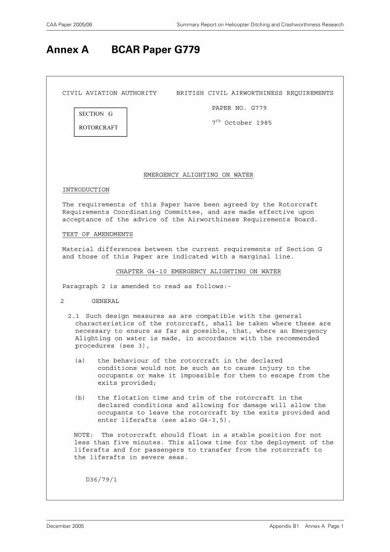
CAA Paper 2005/06 Summary Report on Helicopter Ditching and Crashworthiness Research
Annex A BCAR Paper G779
CIVIL AVIATION AUTHORITY BRITISH CIVIL AIRWORTHINESS REQUIREMENTS PAPER NO. G779 7th October 1985
EMERGENCY ALIGHTING ON WATER
INTRODUCTION
The requirements of this Paper have been agreed by the Rotorcraft Requirements Coordinating Committee, and are made effective upon acceptance of the advice of the Airworthiness Requirements Board.
TEXT OF AMENDMENTS
Material differences between the current requirements of Section G and those of this Paper are indicated with a marginal line.
CHAPTER G4-10 EMERGENCY ALIGHTING ON WATER
Paragraph 2 is amended to read as follows:-
2 GENERAL
2.1 Such design measures as are compatible with the general characteristics of the rotorcraft, shall be taken where these are necessary to ensure as far as possible, that, where an Emergency Alighting on water is made, in accordance with the recommended procedures (see 3),
(a) the behaviour of the rotorcraft in the declared conditions would not be such as to cause injury to the occupants or make it impossible for them to escape from the exits provided;
(b) the flotation time and trim of the rotorcraft in the declared conditions and allowing for damage will allow the occupants to leave the rotorcraft by the exits provided and enter liferafts (see also G4-3,5).
NOTE: The rotorcraft should float in a stable position for not less than five minutes. This allows time for the deployment of the liferafts and for passengers to transfer from the rotorcraft to the liferafts in severe seas.
D36/79/1
SECTION G
ROTORCRAFT
Appendix B1 Annex A Page 1December 2005
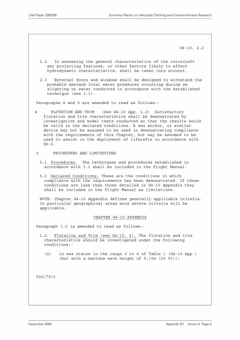
CAA Paper 2005/06 Summary Report on Helicopter Ditching and Crashworthiness Research
G4-10, 2.2
2.2 In assessing the general characteristics of the rotorcraft any projecting features, or other factors likely to affect hydrodynamic characteristics, shall be taken into account.
2.3 External doors and windows shall be designed to withstand the probable maximum local water pressures occurring during an alighting on water conducted in accordance with the established technique (see 3.1).
Paragraphs 4 and 5 are amended to read as follows:-
4 FLOTATION AND TRIM (See G4-10 App. 1.2) Satisfactory flotation and trim characteristics shall be demonstrated by investigation and model tests conducted so that the results would be valid in the declared conditions. A sea anchor, or similar device may not be assumed to be used in demonstrating compliance with the requirements of this Chapter, but may be assumed to be used to assist in the deployment of liferafts in accordance with G6-6.
5 PROCEDURES AND LIMITATIONS
5.1 Procedures. The techniques and procedures established in accordance with 3.1 shall be included in the Flight Manual.
5.2 Declared Conditions. These are the conditions in which compliance with the requirements has been demonstrated. If these conditions are less than those detailed in G4-10 Appendix they shall be included in the Flight Manual as limitations.
NOTE: Chapter G4-10 Appendix defines generally applicable criteria. In particular geographical areas more severe criteria will be applicable.
CHAPTER G4-10 APPENDIX
Paragraph 1.2 is amended to read as follows:-
1.2 Flotation and Trim (see G4-10, 4). The flotation and trim characteristics should be investigated under the following conditions:-
(a) in sea states in the range 0 to 6 of Table 1 (G4-10 App.) (but with a maximum wave height of 9.15m (30 ft));
D36/79/2
Appendix B1 Annex A Page 2December 2005
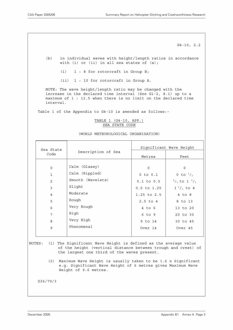
CAA Paper 2005/06 Summary Report on Helicopter Ditching and Crashworthiness Research
G4-10, 2.2
(b) in individual waves with height/length ratios in accordance with (i) or (ii) in all sea states of (a);
(i) 1 : 8 for rotorcraft in Group B;
(ii) 1 : 10 for rotorcraft in Group A.
NOTE: The wave height/length ratio may be changed with the increase in the declared time interval (See G1-2, 8.1) up to a maximum of 1 : 12.5 when there is no limit on the declared time interval.
Table 1 of the Appendix to G4-10 is amended as follows:-
TABLE 1 (G4-10, APP.)SEA STATE CODE
(WORLD METEOROLOGICAL ORGANISATION)
Significant Wave Height Sea State
CodeDescription of Sea
Metres Feet
0
1
2
3
4
5
6
7
8
9
Calm (Glassy)
Calm (Rippled)
Smooth (Wavelets)
Slight
Moderate
Rough
Very Rough
High
Very High
Phenomenal
0
0 to 0.1
0.1 to 0.5
0.5 to 1.25
1.25 to 2.5
2.5 to 4
4 to 6
6 to 9
9 to 14
Over 14
0
0 to 1/32/3 to 1
2/3
1 2/3 to 4
4 to 8
8 to 13
13 to 20
20 to 30
30 to 45
Over 45
NOTES: (1) The Significant Wave Height is defined as the average value of the height (vertical distance between trough and crest) of the largest one third of the waves present.
(2) Maximum Wave Height is usually taken to be 1.6 x Significant e.g. Significant Wave Height of 6 metres gives Maximum Wave Height of 9.6 metres.
D36/79/3
Appendix B1 Annex A Page 3December 2005
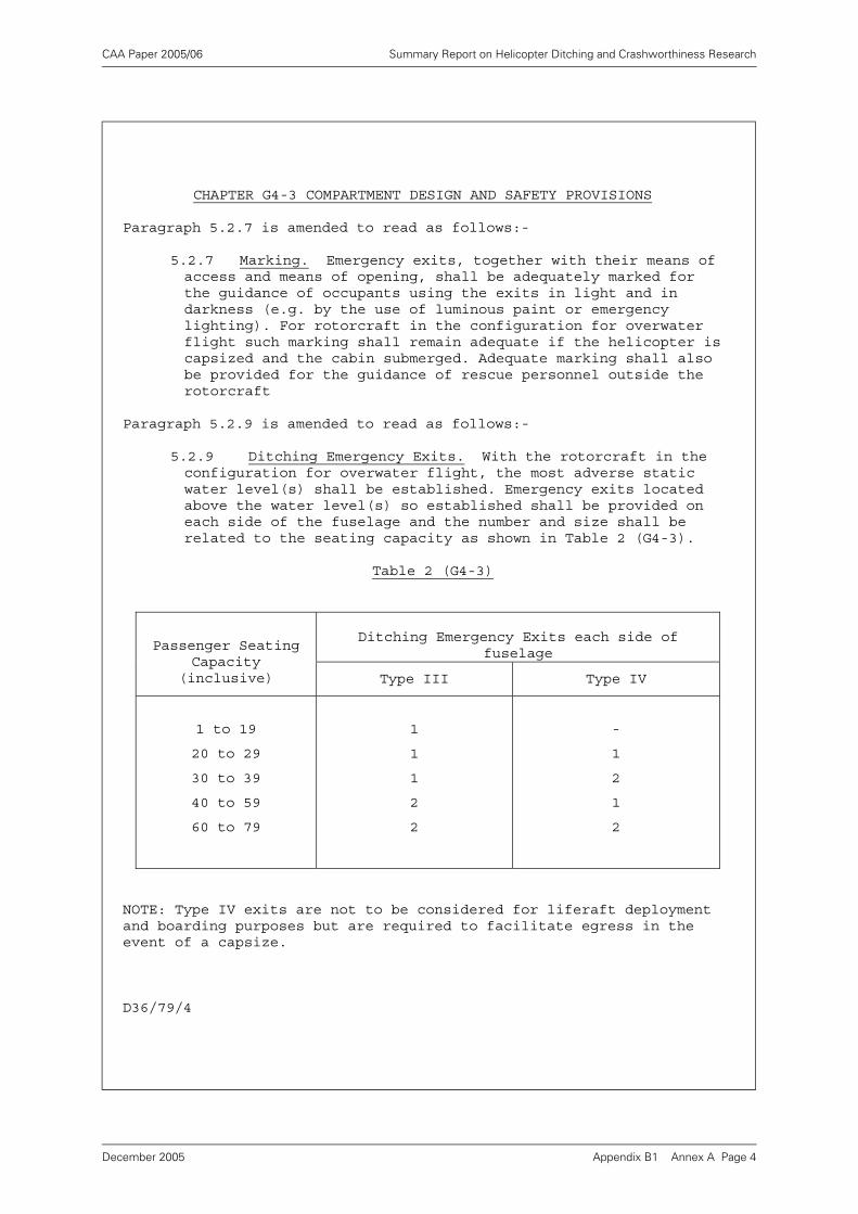
CAA Paper 2005/06 Summary Report on Helicopter Ditching and Crashworthiness Research
CHAPTER G4-3 COMPARTMENT DESIGN AND SAFETY PROVISIONS
Paragraph 5.2.7 is amended to read as follows:-
5.2.7 Marking. Emergency exits, together with their means of access and means of opening, shall be adequately marked for the guidance of occupants using the exits in light and in darkness (e.g. by the use of luminous paint or emergency lighting). For rotorcraft in the configuration for overwater flight such marking shall remain adequate if the helicopter is capsized and the cabin submerged. Adequate marking shall also be provided for the guidance of rescue personnel outside the rotorcraft
Paragraph 5.2.9 is amended to read as follows:-
5.2.9 Ditching Emergency Exits. With the rotorcraft in the configuration for overwater flight, the most adverse static water level(s) shall be established. Emergency exits located above the water level(s) so established shall be provided on each side of the fuselage and the number and size shall be related to the seating capacity as shown in Table 2 (G4-3).
Table 2 (G4-3)
Ditching Emergency Exits each side of fuselage
Passenger Seating Capacity
(inclusive) Type III Type IV
1 to 19
20 to 29
30 to 39
40 to 59
60 to 79
1
1
1
2
2
-
1
2
1
2
NOTE: Type IV exits are not to be considered for liferaft deployment and boarding purposes but are required to facilitate egress in the event of a capsize.
D36/79/4
Appendix B1 Annex A Page 4December 2005
CAA Paper 2005/06 Summary Report on Helicopter Ditching and Crashworthiness Research
Appendix B2 Helicopter Ditching JAR Certification
Requirements
Executive Summary
BMT Fluid Mechanics Ltd. was asked by the Civil Aviation Authority to perform a review ofhelicopter ditching performance and current certification requirements.
The current CAA requirements are mainly defined in British Civil Airworthiness Requirement(BCAR) Paper G779 dated 7th October 1985. This document amended the previous BCARChapter G4-10 and associated Appendix dated 20th January 1975. These requirements werereviewed by BMT and commented on in a previous report [3].
This study has reviewed the similar Joint Airworthiness Requirements (JAR) on ditching, andcompared them with the BCAR requirements reported earlier. The main conclusion was thatthe requirements were very similar in many respects, but an important difference is therequirement for survival in sea state 4 in JAR and sea state 6 in BCAR (but both imply thathigher sea states might be appropriate).
Both JAR and BCAR requirements are ambiguous with regard to the steepness of the wavesthat should be used.
Various recommendations have been made regarding potential improvements to the JARdocuments.
Appendix B2 Page 1December 2005

CAA Paper 2005/06 Summary Report on Helicopter Ditching and Crashworthiness Research
1 Introduction
BMT Fluid Mechanics Ltd. (BMT) was asked [1]1 by the Civil Aviation Authority (CAA)to perform a review of helicopter ditching performance. The review was to lookcritically at the various research reports and review documents that CAA hadcommissioned in recent years, and to summarise and comment on their findings. Anumber of reports have been presented on this work [2, 3, 4, 5, 6].
This present report concerns a review of the Joint Airworthiness Requirements (JAR)for the certification of helicopter ditching. This additional study was ordered in [7]. Thereport is similar to [3] which considered the British Civil Airworthiness Requirements(BCAR) [8].
The objective of the study was to compare the provisions of the JAR with the BCARdocuments, and produce a short report highlighting any naval architectural issues orflotation issues in the JAR documents which appeared to be ambiguous orinadequately defined.
The JAR documentation provided by the CAA for this study were [9] and [10]. Forconvenience these are reproduced in Annex A.
2 Conclusions
2.1 In many ways the provisions of the JAR and BCAR on ditching are similar. They havevery similar statements of objectives which require that the occupants should not beinjured and should be able to escape the rotorcraft. There is some difference inwording relating to: “practicable design measures” in the case of the JAR, and “as
far as possible” in the case of the BCAR. It might be argued that the latter is a moreonerous requirement.
2.2 The scope of the JAR document is somewhat broader than the BCAR and it includesmore requirements relating to water entry and strength than found in the particularBCAR document reviewed. These aspects may be covered in more detail in otherBCAR sections, but were not of prime interest for this study where flotation, trim andstability are the main concerns.
2.3 With regard to the severity of the wave conditions that the designer mustdemonstrate that the rotorcraft can cope with, the key phrase in the JAR is“reasonably probable water conditions”. The wording is not ideal, but it is believedthat this should be interpreted to mean the majority of wave conditions that therotorcraft might be expected to meet, with the consequence that the probability ofmeeting a more severe condition is reasonably rare. Taken on its own, this wouldrequire the designer to select a reasonably severe wave condition for the area inwhich he expects the aircraft to operate. However, later in the JAR guidance this isinterpreted to mean “not less than sea state 4”. It is expected that most designerswill therefore just demonstrate compliance with sea state 4, a condition which isexceeded for a large percentage of the time in many of the world's oceans.
2.4 BCAR is more onerous in terms of sea states, quoting sea state 6, and also invitingthe possibility that even more severe conditions should be considered in particulargeographical areas.
1. References are to be found in Section 4 on page 8.
Appendix B2 Page 2December 2005
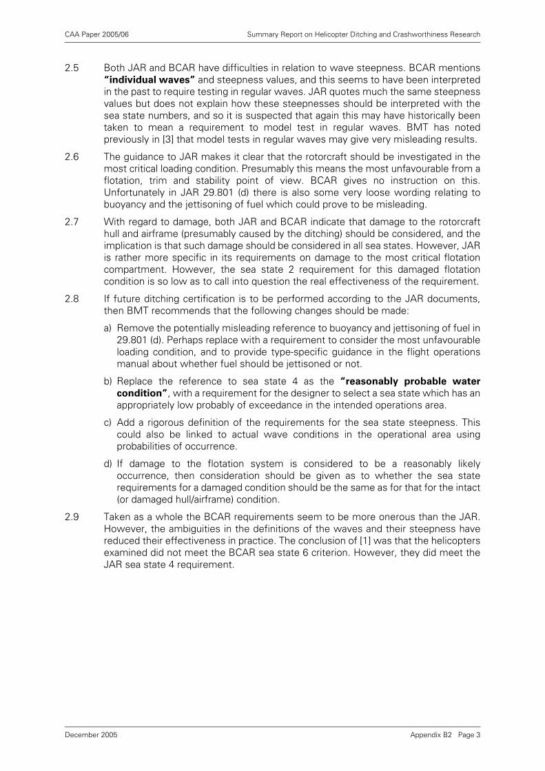
CAA Paper 2005/06 Summary Report on Helicopter Ditching and Crashworthiness Research
2.5 Both JAR and BCAR have difficulties in relation to wave steepness. BCAR mentions“individual waves” and steepness values, and this seems to have been interpretedin the past to require testing in regular waves. JAR quotes much the same steepnessvalues but does not explain how these steepnesses should be interpreted with thesea state numbers, and so it is suspected that again this may have historically beentaken to mean a requirement to model test in regular waves. BMT has notedpreviously in [3] that model tests in regular waves may give very misleading results.
2.6 The guidance to JAR makes it clear that the rotorcraft should be investigated in themost critical loading condition. Presumably this means the most unfavourable from aflotation, trim and stability point of view. BCAR gives no instruction on this.Unfortunately in JAR 29.801 (d) there is also some very loose wording relating tobuoyancy and the jettisoning of fuel which could prove to be misleading.
2.7 With regard to damage, both JAR and BCAR indicate that damage to the rotorcrafthull and airframe (presumably caused by the ditching) should be considered, and theimplication is that such damage should be considered in all sea states. However, JARis rather more specific in its requirements on damage to the most critical flotationcompartment. However, the sea state 2 requirement for this damaged flotationcondition is so low as to call into question the real effectiveness of the requirement.
2.8 If future ditching certification is to be performed according to the JAR documents,then BMT recommends that the following changes should be made:
a) Remove the potentially misleading reference to buoyancy and jettisoning of fuel in29.801 (d). Perhaps replace with a requirement to consider the most unfavourableloading condition, and to provide type-specific guidance in the flight operationsmanual about whether fuel should be jettisoned or not.
b) Replace the reference to sea state 4 as the “reasonably probable water
condition”, with a requirement for the designer to select a sea state which has anappropriately low probably of exceedance in the intended operations area.
c) Add a rigorous definition of the requirements for the sea state steepness. Thiscould also be linked to actual wave conditions in the operational area usingprobabilities of occurrence.
d) If damage to the flotation system is considered to be a reasonably likelyoccurrence, then consideration should be given as to whether the sea staterequirements for a damaged condition should be the same as for that for the intact(or damaged hull/airframe) condition.
2.9 Taken as a whole the BCAR requirements seem to be more onerous than the JAR.However, the ambiguities in the definitions of the waves and their steepness havereduced their effectiveness in practice. The conclusion of [1] was that the helicoptersexamined did not meet the BCAR sea state 6 criterion. However, they did meet theJAR sea state 4 requirement.
Appendix B2 Page 3December 2005
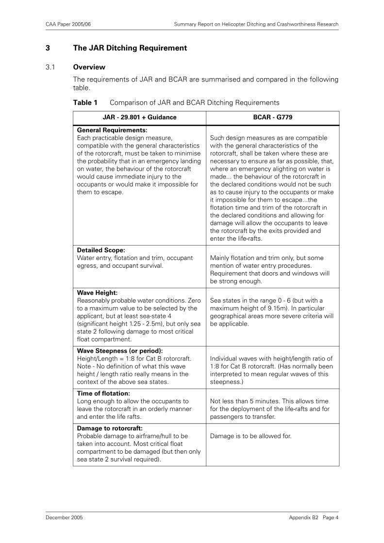
CAA Paper 2005/06 Summary Report on Helicopter Ditching and Crashworthiness Research
3 The JAR Ditching Requirement
3.1 Overview
The requirements of JAR and BCAR are summarised and compared in the followingtable.
Table 1 Comparison of JAR and BCAR Ditching Requirements
JAR - 29.801 + Guidance BCAR - G779
General Requirements:
Each practicable design measure, compatible with the general characteristics of the rotorcraft, must be taken to minimise the probability that in an emergency landing on water, the behaviour of the rotorcraft would cause immediate injury to the occupants or would make it impossible for them to escape.
Such design measures as are compatible with the general characteristics of the rotorcraft, shall be taken where these are necessary to ensure as far as possible, that, where an emergency alighting on water is made... the behaviour of the rotorcraft in the declared conditions would not be such as to cause injury to the occupants or make it impossible for them to escape...the flotation time and trim of the rotorcraft in the declared conditions and allowing for damage will allow the occupants to leave the rotorcraft by the exits provided and enter the life-rafts.
Detailed Scope:
Water entry, flotation and trim, occupant egress, and occupant survival.
Mainly flotation and trim only, but some mention of water entry procedures. Requirement that doors and windows will be strong enough.
Wave Height:
Reasonably probable water conditions. Zero to a maximum value to be selected by the applicant, but at least sea-state 4 (significant height 1.25 - 2.5m), but only sea state 2 following damage to most critical float compartment.
Sea states in the range 0 - 6 (but with a maximum height of 9.15m). In particular geographical areas more severe criteria will be applicable.
Wave Steepness (or period):
Height/Length = 1:8 for Cat B rotorcraft. Note - No definition of what this wave height / length ratio really means in the context of the above sea states.
Individual waves with height/length ratio of 1:8 for Cat B rotorcraft. (Has normally been interpreted to mean regular waves of this steepness.)
Time of flotation:
Long enough to allow the occupants to leave the rotorcraft in an orderly manner and enter the life rafts.
Not less than 5 minutes. This allows time for the deployment of the life-rafts and for passengers to transfer.
Damage to rotorcraft:
Probable damage to airframe/hull to be taken into account. Most critical float compartment to be damaged (but then only sea state 2 survival required).
Damage is to be allowed for.
Appendix B2 Page 4December 2005
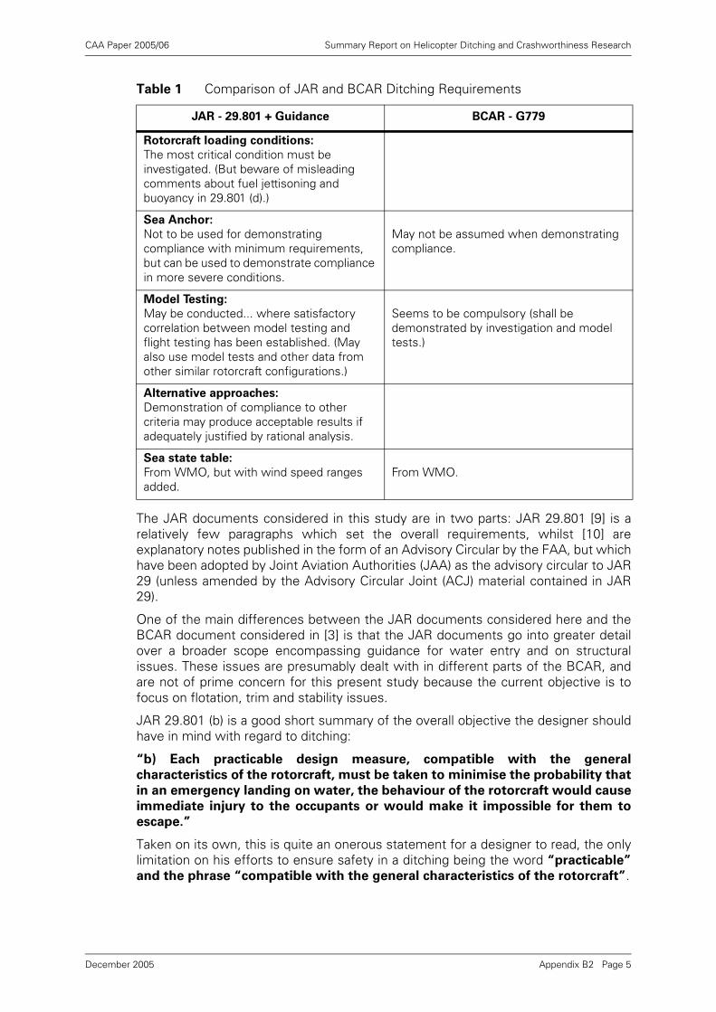
CAA Paper 2005/06 Summary Report on Helicopter Ditching and Crashworthiness Research
The JAR documents considered in this study are in two parts: JAR 29.801 [9] is arelatively few paragraphs which set the overall requirements, whilst [10] areexplanatory notes published in the form of an Advisory Circular by the FAA, but whichhave been adopted by Joint Aviation Authorities (JAA) as the advisory circular to JAR29 (unless amended by the Advisory Circular Joint (ACJ) material contained in JAR29).
One of the main differences between the JAR documents considered here and theBCAR document considered in [3] is that the JAR documents go into greater detailover a broader scope encompassing guidance for water entry and on structuralissues. These issues are presumably dealt with in different parts of the BCAR, andare not of prime concern for this present study because the current objective is tofocus on flotation, trim and stability issues.
JAR 29.801 (b) is a good short summary of the overall objective the designer shouldhave in mind with regard to ditching:
“b) Each practicable design measure, compatible with the general
characteristics of the rotorcraft, must be taken to minimise the probability that
in an emergency landing on water, the behaviour of the rotorcraft would cause
immediate injury to the occupants or would make it impossible for them to
escape.”
Taken on its own, this is quite an onerous statement for a designer to read, the onlylimitation on his efforts to ensure safety in a ditching being the word “practicable”
and the phrase “compatible with the general characteristics of the rotorcraft”.
Rotorcraft loading conditions:
The most critical condition must be investigated. (But beware of misleading comments about fuel jettisoning and buoyancy in 29.801 (d).)
Sea Anchor:
Not to be used for demonstrating compliance with minimum requirements, but can be used to demonstrate compliance in more severe conditions.
May not be assumed when demonstrating compliance.
Model Testing:
May be conducted... where satisfactory correlation between model testing and flight testing has been established. (May also use model tests and other data from other similar rotorcraft configurations.)
Seems to be compulsory (shall be demonstrated by investigation and model tests.)
Alternative approaches:
Demonstration of compliance to other criteria may produce acceptable results if adequately justified by rational analysis.
Sea state table:
From WMO, but with wind speed ranges added.
From WMO.
Table 1 Comparison of JAR and BCAR Ditching Requirements
JAR - 29.801 + Guidance BCAR - G779
Appendix B2 Page 5December 2005
CAA Paper 2005/06 Summary Report on Helicopter Ditching and Crashworthiness Research
In many ways this statement is very similar to initial paragraphs of the BCAR G779where the same overall objectives (not to cause injury to occupants, and to enablethem to escape) are given. The main difference is the use of the words “as far as
possible” in the BCAR document, which it might be argued placed a strongerrequirement on the designer to search for all possible ways of improving the ditchingsafety.
In some ways all the prescriptive requirements and guidance that follow thisstatement in both the JAR and BCAR make the requirements less onerous (forexample the BCAR document goes on immediately to require that the rotorcraft floatsin a stable position for not less than 5 minutes).
3.2 Detailed Comments
It is noted that on page 553 of [10] a ditching is defined to be “an emergency landing
on water” which is “deliberately executed”, and that the rotorcraft is assumed “to
be intact prior to water entry”. However, later on page 558 it says that “probable
damage to the airframe/hull ... should be considered” when demonstratingcompliance with the flotation and trim requirements. Thus damage sustained duringthe ditching process is to be considered, and more specifically on page 557 it is clearthat the “flotation and trim should be evaluated with a simulated, ruptured
deflation of the most critical float compartment”, although in this condition therequired sea state is relaxed from sea state 4 to 2. These requirements on damageare rather more specific than the BCAR requirements.
The BCAR paper requires the helicopter to float in a stable position for “not less than
5 minutes”. No specific period of time is mentioned in the JAR requirements, but itis clear that the rotorcraft must remain floating at a reasonable attitude for a timesufficient for all the occupants to escape (29.801 d).
The essence of the JAR requirement in terms of sea-states that the helicopter mustbe able to cope with is given in (d) of JAR 29.801 where they are defined as“reasonably probable conditions”. In [10] this is interpreted to mean “at least sea
state 4”, the explanation being that “sea state 4 is representative of reasonably
probable water conditions to be encountered”.
It is not completely clear what is intended here. If the helicopter were to be justcapable of handling average conditions, then we might expect it to capsize on manyoccasions (50% of ditching occasions if the sea state probability distribution were tobe symmetrical). It seems more likely that the writer of the JAR intended that thehelicopter would be able to cope with the majority of or all of the reasonablyprobable water conditions. This would mean that it should cope with sea statesforming most of the sea-state population, and a capsize following a ditching shouldbe a relatively rare occurrence. This would also be consistent with the initialstatement of objectives regarding not causing injury to occupants, and enabling themto escape.
Clearly the helicopter designer is at liberty to choose any sea-state condition that hewishes to demonstrate compliance with, and presumably he could justify in hissubmission that these represent “reasonably probable conditions”. However, theguidance that sea state 4 represents such a sea condition seems to absolve thedesigner of selecting one himself, and obviously takes no account of the vast rangeof ocean wave climates that exist around the world. The sea state code table definesa sea state 4 as 1.25 - 2.5m and a wind speed in the range 17 - 21 kn. In the Gulf ofMexico 2.5m significant wave height is exceeded for only about 20% of the time,whilst in the northern North Sea or West of Shetlands it is exceeded 50-60% of thetime. In the Gulf of Mexico 21kn wind speed is exceeded for only 10% of the timewhilst in the northern North Sea or West of Shetlands it is exceeded for 35% of thetime.
Appendix B2 Page 6December 2005
CAA Paper 2005/06 Summary Report on Helicopter Ditching and Crashworthiness Research
If the presumption about the intention of the writer is correct (that he intendedcapsizes following a ditching to be relatively rare) then we can deduce that the writerwas thinking of an area of the sea where the incidence of sea state 4 and higher wasreasonably unusual (such as the Gulf of Mexico).
The major contrast here is with the BCAR document which implies that the helicoptershould be able to cope with sea state 6, and also offers the possibility that moresevere criteria may be appropriate in particular geographical areas. However, as hasbeen shown in [2] none of the helicopter types considered in the BHC model testsseemed to comply with a sea state 6 requirement. On the basis of existinghelicopters therefore, sea state 4 might seem to be the requirement that they cancurrently comply with, but it obviously carries with it a significant risk of immediatecapsize following ditching in many parts of the world.
Paragraph (d) of JAR 29.801 seems to make the classic mistake of confusingbuoyancy with weight when it refers to the ability of the helicopter to jettison fuel. Ifthe helicopter and its fuel tanks remain structurally intact, then the buoyancy (abilityto displace water volume) is unchanged however much fuel is on board. What doeschange if fuel is jettisoned is the helicopter weight and centre of gravity position.The weight will reduce and the centre of gravity position will be raised (which is quitelikely to lead to a degradation of static stability).
It seems that there ought here to be instead a statement on the lines of ensuring thatthe helicopter is stable for the most critical weight conditions (whatever these are),and a requirement to provide guidance in the flight manual about whether fuel shouldbe jettisoned or not. In fact the guidance document [10] does mention the mostcritical loading condition on page 557.
BCAR G779 does not mention rotorcraft loading conditions at all.
Wave steepness is a serious area of ambiguity in the JAR as it is in the BCAR. Thelatter also has mention of `individual waves' of certain steepness, which has lead tomodel testing in regular waves of a particular steepness, and BMT has previouslyindicated in [1] how results from model tests in such steep regular waves might bemisleading.
The problem with the wave height / length ratios stated in the JAR is that there is noguidance on how these steepnesses are to be interpreted in the context of the seastate criteria. The reliance on a sea state implies that the model testing or analysismust be performed for irregular waves which realistically represent an ocean seastate. Unfortunately, in irregular waves it is possible to define many different wavesteepnesses: Some examples are:
a) Significant height Hs: Wave length associated with the Significant Period Ts.
b) Significant height Hs: Wave length associated with the Zero Crossing Period Tz.
c) Significant height Hs: Wave length associated with the Modal (peak energy) PeriodT0.
d) Significant height Hs: Wave length associated with the Average Period T1.
e) Maximum wave height Hmax: Wave length associated with the maximum waveheight Hmax.
f) Significant steepness (calculated from a steepness spectrum).
Unfortunately most of these definitions give very different steepness values. Forexample the steepness calculated according to (b) will be about a factor of 2 differentfrom that calculated according to (c).
λ
Appendix B2 Page 7December 2005
CAA Paper 2005/06 Summary Report on Helicopter Ditching and Crashworthiness Research
It is suspected that the writer of the JAR may have had in mind something akin to (v)above, but the wavelength associated with the largest wave in an irregular sea isextremely difficult to define.
The JAR (like the BCAR) therefore leaves the impression that there is a requirementto demonstrate that the rotorcraft can survive in steep seas, but it falls short of aproper definition of what the steepness should actually be. It is likely therefore thathelicopter designers and model testers will consequently revert to using regularwaves, where the steepness has a clear definition (as seems to have been the casewith the historic interpretation of the BCAR).
3.3 Overall Impressions
The overall impression is that the JAR places a less onerous requirement on therotorcraft designer than does the BCAR. This is certainly the case in terms of the seastates in which acceptable flotation and trim are to be demonstrated, but also seemsto be the case in some of the other more general wording.
Both BCAR and JAR are very ambiguous in their definition of wave steepness (andBCAR has further unclear wording which seems to imply that tests in regular wavesare acceptable).
Helicopter model tests performed by BHC and summarised in [1] demonstrated thatnone of the types tested met the BCAR sea state 6 requirement, but they did meetthe JAR sea state 4 requirement.
4 References
[1] CAA Contract No. 7D/S/1096 dated 16th December 1992.
[2] BMT Report 44011r12 Review of Helicopter Ditching Performance, Report 1,Release 2, 2nd July 1993.
[3] BMT Report 44011r21 Review of Helicopter Ditching CertificationRequirements, Report 2, Release 1, 6th July 1993.
[4] BMT Report 44011r31 Review of Helicopter Ditching Performance - A PotentialProbabilistic Methodology, Report 3, Release 1, 20th August 1993.
[5] BMT Report 44035r14 Helicopter Float Scoops, Report 1 Release 4, 30th June1995.
[6] BMT Report 44035r23 Means to Prevent Helicopter Total Inversion Following aDitching, Report 2, Release 3, 30th June 1995.
[7] Contract No 7D/S/1096/1, Review of Helicopter Ditching Performance,Amendment 2, 25th May 1995.
[8] Civil Aviation Authority, British Civil Airworthiness Requirements, Paper No.G779, 7th October 1985.
[9] JAR 29.801 from Joint Aviation Requirements JAR-29 Large Rotorcraft, CivilAviation Authority (on behalf of the Joint Aviation Authorities Committee), 5thNovember 1993.
[10] Advisory Circular No. 29-2A, Change 2, Certification of Transport CategoryRotorcraft, Federal Aviation Administration, 24th September 1991.
Appendix B2 Page 8December 2005
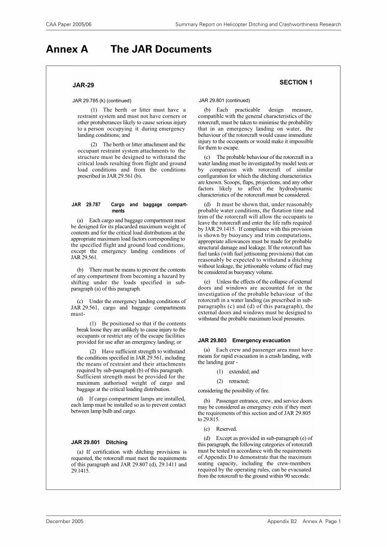
CAA Paper 2005/06 Summary Report on Helicopter Ditching and Crashworthiness Research
Annex A The JAR Documents
JAR-29 SECTION 1
JAR 29.785 (k) (continued)
(1) The berth or litter must have a restraint system and must not have corners or other protuberances likely to cause serious injury to a person occupying it during emergency landing conditions; and
(2) The berth or litter attachment and the occupant restraint system attachments to the structure must be designed to withstand the critical loads resulting from flight and ground load conditions and from the conditions prescribed in JAR 29.561 (b).
JAR 29.787 Cargo and baggage compart-
ments
(a) Each cargo and baggage compartment must be designed for its placarded maximum weight of contents and for the critical load distributions at the appropriate maximum load factors corresponding to the specified flight and ground load conditions, except the emergency landing conditions of JAR 29.561.
(b) There must be means to prevent the contents of any compartment from becoming a hazard by shifting under the loads specified in sub- paragraph (a) of this paragraph.
(c) Under the emergency landing conditions of JAR 29.561, cargo and baggage compartments must-
(1) Be positioned so that if the contents break loose they are unlikely to cause injury to the occupants or restrict any of the escape facilities provided for use after an emergency landing; or
(2) Have sufficient strength to withstand the conditions specified in JAR 29.561, including the means of restraint and their attachments required by sub-paragraph (b) of this paragraph. Sufficient strength must be provided for the maximum authorised weight of cargo and baggage at the critical loading distribution.
(d) If cargo compartment lamps are installed, each lamp must be installed so as to prevent contact between lamp bulb and cargo.
JAR 29.801 Ditching
(a) If certification with ditching provisions is requested, the rotorcraft must meet the requirements of this paragraph and JAR 29.807 (d), 29.1411 and 29.1415.
JAR 29.801 (continued)
(b) Each practicable design measure, compatible with the general characteristics of the rotorcraft, must be taken to minimise the probability that in an emergency landing on water, the behaviour of the rotorcraft would cause immediate injury to the occupants or would make it impossible for them to escape.
(c) The probable behaviour of the rotorcraft in a water landing must be investigated by model tests or by comparison with rotorcraft of similar configuration for which the ditching characteristics are known. Scoops, flaps, projections, and any other factors likely to affect the hydrodynamic characteristics of the rotorcraft must be considered.
(d) It must be shown that, under reasonably probable water conditions, the flotation time and trim of the rotorcraft will allow the occupants to leave the rotorcraft and enter the life rafts required by JAR 29.1415. If compliance with this provision is shown by buoyancy and trim computations, appropriate allowances must be made for probable structural damage and leakage. If the rotorcraft has fuel tanks (with fuel jettisoning provisions) that can reasonably be expected to withstand a ditching without leakage, the jettisonable volume of fuel may be considered as buoyancy volume.
(e) Unless the effects of the collapse of external doors and windows are accounted for in the investigation of the probable behaviour of the rotorcraft in a water landing (as prescribed in sub- paragraphs (c) and (d) of this paragraph), the external doors and windows must be designed to withstand the probable maximum local pressures.
JAR 29.803 Emergency evacuation
(a) Each crew and passenger area must have means for rapid evacuation in a crash landing, with the landing gear -
(1) extended; and
(2) retracted;
considering the possibility of fire.
(b) Passenger entrance, crew, and service doors may be considered as emergency exits if they meet the requirements of this section and of JAR 29.805 to 29.815.
(c) Reserved.
(d) Except as provided in sub-paragraph (e) of this paragraph, the following categories of rotorcraft must be tested in accordance with the requirements of Appendix D to demonstrate that the maximum seating capacity, including the crew-members required by the operating rules, can be evacuated from the rotorcraft to the ground within 90 seconds:
Appendix B2 Annex A Page 1December 2005
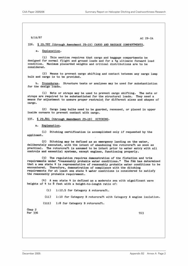
CAA Paper 2005/06 Summary Report on Helicopter Ditching and Crashworthiness Research
Appendix B2 Annex A Page 2December 2005
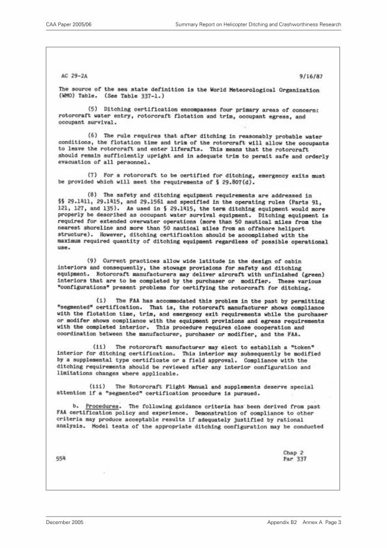
CAA Paper 2005/06 Summary Report on Helicopter Ditching and Crashworthiness Research
Appendix B2 Annex A Page 3December 2005
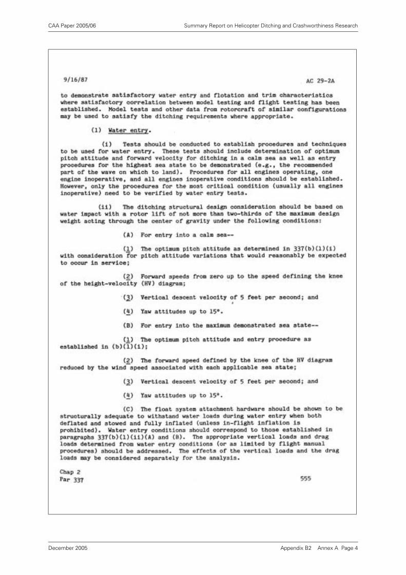
CAA Paper 2005/06 Summary Report on Helicopter Ditching and Crashworthiness Research
Appendix B2 Annex A Page 4December 2005
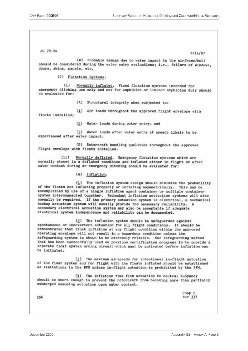
CAA Paper 2005/06 Summary Report on Helicopter Ditching and Crashworthiness Research
Appendix B2 Annex A Page 5December 2005
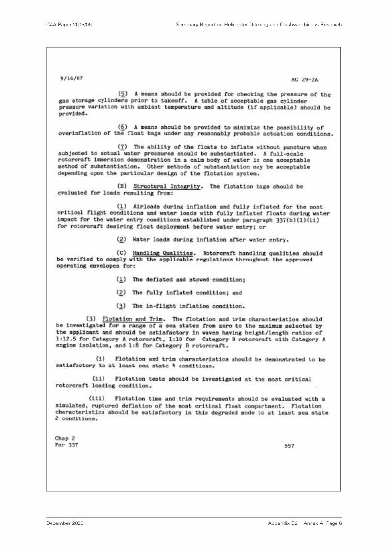
CAA Paper 2005/06 Summary Report on Helicopter Ditching and Crashworthiness Research
Appendix B2 Annex A Page 6December 2005
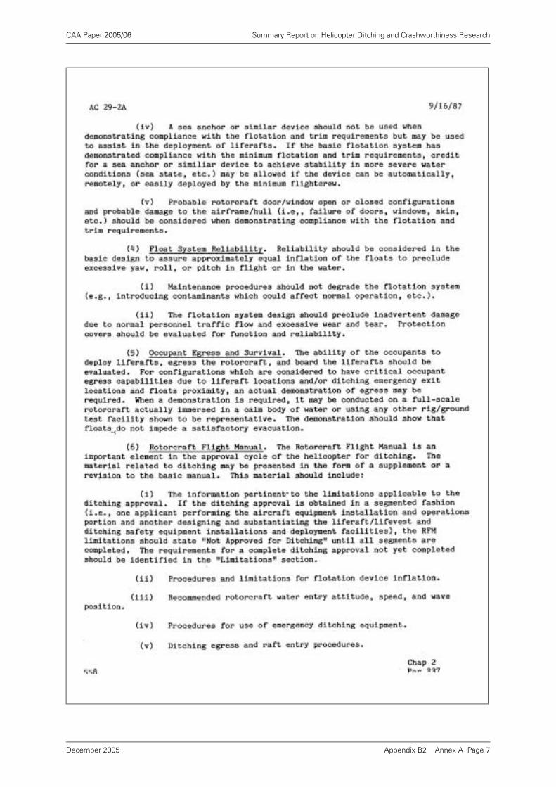
CAA Paper 2005/06 Summary Report on Helicopter Ditching and Crashworthiness Research
Appendix B2 Annex A Page 7December 2005
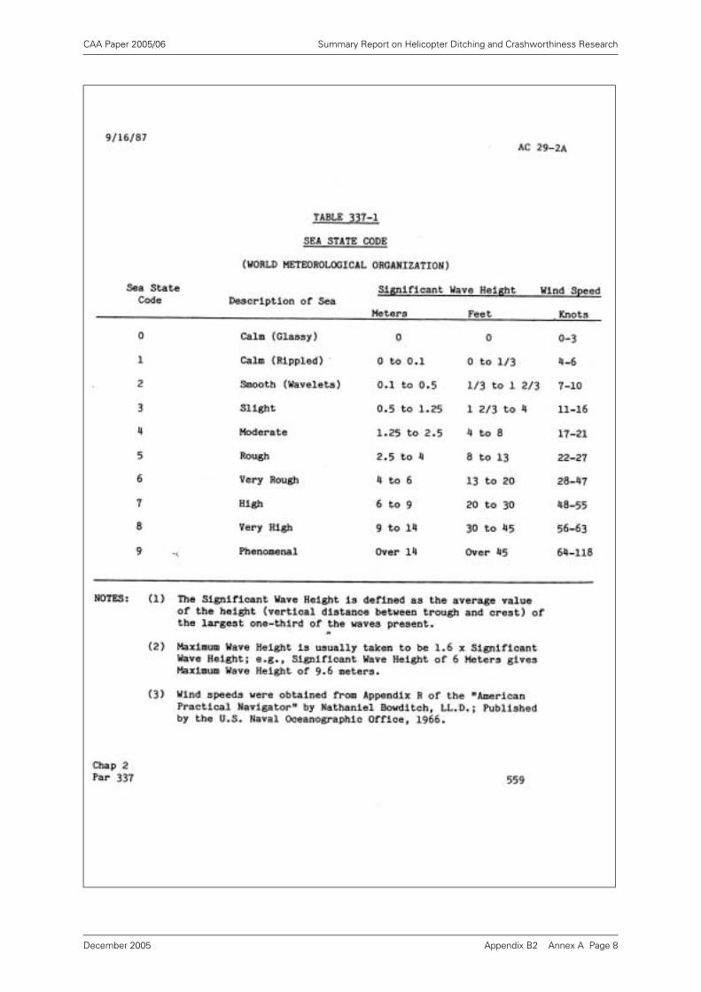
CAA Paper 2005/06 Summary Report on Helicopter Ditching and Crashworthiness Research
Appendix B2 Annex A Page 8December 2005
CAA Paper 2005/06 Summary Report on Helicopter Ditching and Crashworthiness Research
Appendix C Review of Helicopter Ditching:
A Potential Probabilistic Methodology
Executive Summary
BMT Offshore Ltd. was asked by the Civil Aviation Authority to perform a review of helicopterditching performance and current certification requirements.
An earlier report [6] considered and discussed the existing information on the factorsinfluencing the on-water stability of current helicopter types. A second report [7] consideredthe current certification requirements. This third report summarises the findings of the firsttwo, and then investigates a possible probabilistic approach to this aspect of helicoptercertification.
It has been shown that the mechanisms behind helicopter capsize are very complex, and arenot well understood. The results of many model tests on different types have not resulted inmuch physical understanding of the controlling phenomena, but have demonstrated thatcertain measures (e.g. float scoops) can increase resistance to capsize. It is believed thatphysical understanding of the processes requires further theoretical simulation work backedup by appropriate good quality experimental validation.
It has been shown that the current CAA helicopter certification requirements regardingditching appear to be deficient in a number of respects, most notably in the way in whichlimiting wave conditions are defined. It has been proposed that these could be improved, inparticular by requiring capsize performance to be demonstrated in irregular waves which,whilst presenting some significant model testing difficulties, offer a much more realisticapproach than using regular waves, which can potentially give a quite misleading impression.
A simple analysis of civil and military helicopter ditching occurrences has indicated that the riskto the individual offshore worker of suffering a fatality due to helicopter capsize following acontrolled ditching is probably less than 3×10⁻⁵ per year (or about once every 30,000 manyears).
Finally, a move away from a prescriptive wave condition requirement has been suggested. Thiswould instead set 'risk of capsize' targets that the designer would be required to demonstrateare achieved by the helicopter in a defined 'operating area'.
Appendix C Page 1December 2005
CAA Paper 2005/06 Summary Report on Helicopter Ditching and Crashworthiness Research
1 Introduction
BMT Offshore Ltd. (BMT) was asked [1]1 by the Civil Aviation Authority (CAA) topropose a review of helicopter ditching performance. BMT responded with a proposal[2], and based on this proposal, CAA put in place a contract for the work to beperformed [3].
The review was to look critically at the various research reports and reviewdocuments that CAA had commissioned in recent years, and to summarise andcomment on their findings.
1.1 Objectives
The objectives of the overall study were stated to be [2] as follows:
a) Perform a critical review of a number of documents with the objective of drawingconclusions from this work and prepare an overview document (or documents)suitable for publication by CAA.
b) Perform a critical review of the current UK Emergency Alighting on Waterhelicopter design requirements as specified by BCAR Paper No G779 dated 7thOctober 1985 [4], and where appropriate make recommendations on how theserequirements might be improved, and whether there are better ways of assessinga helicopter's water-borne stability.
c) Based on the results of (a) and (b) above, and the results of a separate study [5],review North Sea helicopter ditching performance over the past 20 years andassess the practicality of imposing a new probability-based methodology for NorthSea helicopter operations, taking account of specific type's ditching rates, capsizeprobability and operating environment.
Task (a) above was reported in [6], and task (b) in [7]. This third report brieflysummarises the findings of [6] and [7] and then deals with the results of task (c)above.
1.2 Background
The stated objective in the certification of a helicopter in relation to ditching in the seais that the helicopter should remain upright for sufficient time for the occupants toescape (at least 5 minutes). This implies that there should be an acceptably lowprobability of meeting a wave large enough to capsize the helicopter in this shortperiod of time.
The probability of experiencing a capsize is dependent on two key factors:
a) The height and period or slope of wave required to capsize the helicopter, and
b) the probability of experiencing such a wave, or larger, during the exposure period.
1. References are to be found in Section 7 on Page 14.
Appendix C Page 2December 2005
CAA Paper 2005/06 Summary Report on Helicopter Ditching and Crashworthiness Research
2 Conclusions and Recommendations
2.1 Current Understanding of Helicopter Capsize
BMT has conducted an extensive review of current understanding of helicopterresistance to capsize following ditching. This review, which is reported fully in Ref [6],concentrated on research reports commissioned by CAA over recent years, but alsoconsidered other relevant data in the public domain. The main conclusions from thisreview were as follows:
2.1.1 That the helicopter types studied all had little difficulty in complying with the regularwave steepness certification requirements, but all capsized in irregular waveconditions less severe than the BCAR limit of sea-state 6.
2.1.2 That only very weak correlations were seen between helicopter resistance to capsizeand the physical parameters (e.g. roll inertia) expected to influence it.
2.1.3 That model tests of the type used to generate the data are extremely difficult toperform in an accurate and repeatable way, and that this may explain some of thedifficulty experienced in correlating the results.
2.1.4 That ideally such model tests should provide a quantitative measure of the probabilityof capsize in a given duration of exposure to the sea-state.
2.1.5 That model tests in the presence of wind (where most helicopters have a strongertendency to weathervane) demonstrate a greater resistance to capsize thus indicatingthat any device (e.g. a sea anchor) that maintains a heading into the waves will assistin preventing capsize.
2.1.6 That helicopter capsize is generally only caused by breaking waves.
2.1.7 That float scoops appear to give a significant benefit in reducing the helicopter'stendency to capsize.
2.1.8 That raising floats (the so-called 'wet floor' technique) requires much furtherinvestigation before it can be said to offer any advantage.
2.1.9 That previous theoretical analysis of helicopter motions (intended primarily to derivefloat scoop loads) was seriously flawed, but that further correctly framed computersimulations could be a useful basis on which to build future work.
2.1.10 That an initial analysis of helicopter capsize incidents suggests that about 30%capsize, which contrasts with the IOS theoretical estimate of 5% and the CAAobjective of 1%.
The main recommendations resulting from the review were:
2.1.11 That future certification model tests on helicopters should be performed in irregularwaves, and that consideration should be given to the development of a model testingstandard.
2.1.12 That means should be sought to reduce the risk of capsize following ditching, as itseems to be significantly higher than CAA stated objectives.
2.1.13 That better understanding of helicopter behaviour in steep and breaking waves couldbe obtained from the development of a computer simulation, and that this simulationcould be initially validated against carefully controlled model tests.
2.1.14 That the concept of float scoops should be developed further because they appear tooffer a significant benefit in resistance to capsize.
Appendix C Page 3December 2005

CAA Paper 2005/06 Summary Report on Helicopter Ditching and Crashworthiness Research
2.1.15 That the 'wet-floor' technique requires further study before it can be considered as apotential means of improving resistance to capsize.
2.1.16 That further consideration should be given to measures (such as cowling floats) thatprevent a permanent inverted attitude following an initial capsize.
2.1.17 That the probabilistic capsize work should be extended to cope with varyingprobability of capsize with wave height, and the methods then used in conjunctionwith the more reliable long term North Sea wave data sets to derive probabilities ofcapsize.
2.2 Current Helicopter Ditching Certification Requirements
BMT has reviewed the current certification requirements with regard to emergencyalighting on water as defined in BCAR Paper G779 (1985) [4] and reported its findingsin Ref [7]. The main conclusions of the study were as follows:
2.2.1 That the current helicopter certification requirements in respect of ditching and afloatstability are ambiguous and incomplete in some respects.
2.2.2 That the ambiguity lies mainly in terms of the definition of the waves in which a stablefloating attitude must be demonstrated, whether more severe conditions should beselected in some circumstances, whether the helicopter should be considered tohave sustained any damage, and in the results required from model tests intended todemonstrate compliance.
2.2.3 That historical interpretation of these requirements seems to have concentrated onthe regular wave steepness requirements (none of the helicopters types examinedseemed to comply with the irregular wave requirements).
Consequently, the main recommendations were:
2.2.4 That the certification requirements should be amended to remove the ambiguities.
2.2.5 That there was a choice in terms of how this amendment should be made. Oneapproach would be to keep the existing structure of the requirement, but to definethe wave conditions in which stability was to be demonstrated more rigorously. Analternative approach would be to leave the selection of sea-states to the designer andrequire him to demonstrate an adequately low risk of capsize in the intendedoperational area.
2.2.6 That model tests in regular waves against a specific steepness criterion should bediscouraged as, owing to the fact that capsize only normally occurs in breaking waves,the results are likely to depend more on the wave basin properties than the helicopterproperties.
2.3 Practicality of Imposing a New Probability-Based Methodology
The current helicopter ditching certification requirements have been contrasted witha probabilistic or risk-based method having some similarities with the current 'safetycase' approach being adopted in the certification of offshore installations. The mainconclusions of this part of the study are:
2.3.1 That the current individual risk experienced by a typical offshore worker associatedwith being killed as a result of a helicopter capsize following a controlled ditching isprobably less than 3×10⁻⁵ per year (or about once every 30,000 man years).
2.3.2 That a probabilistic or risk-based certification approach would make the certificationdependent on the intended area of operation of the helicopter, and would thereforegive due design benefit to those helicopters which were only intended to operate inbenign areas.
Appendix C Page 4December 2005
CAA Paper 2005/06 Summary Report on Helicopter Ditching and Crashworthiness Research
2.3.3 That it would also set the certification requirements in context with other CAA safetyor risk level objectives.
2.3.4 That the ease with which such a new certification approach could be implementeddepends on the extent to which CAA already has, or could develop, appropriate risktargets.
Consequently the main recommendations are:
2.3.5 CAA should review internal safety and risk criteria and consider how these can formthe basis of certification for ditching.
2.3.6 CAA should consider the implications of following such a policy on other wideraspects of aircraft certification.
2.3.7 That it may be appropriate to perform a detailed risk analysis of helicopter incidentsin order to set the overall safety and risk targets into context, and to permitapportionment of risk target components to specific incidents such as ditching.
2.3.8 Providing such targets can be arrived at, there should be comparatively little difficultyin modifying the ditching certification requirements to place the onus on the designerto demonstrate that target capsize risk levels have been achieved in the helicopteroperating area.
3 Helicopter Ditching Performance - Current Understanding
BMT conducted a review [6] of current understanding of helicopter ditching. Thisreview studied a number of theoretical and experimental research reportscommissioned by the CAA in recent years, and also performed a literature search ofavailable information in the public domain. The study was confined to considerhelicopters that are floating upright and intact, having alighted on the water in areasonably controlled manner.
The study carefully re-analysed and re-presented the results of numerous model testsmade on a number of different helicopter types, floating in various conditions and withvarious novel configurations including; raised floats ('wet floor'), with added floatscoops, and in one case with engine cowl floats.
One of the objectives of this analysis was to try to identify what the main controllingphysical influences are on helicopter capsize in waves, and to this end, attempts weremade to correlate the data with various non-dimensional helicopter parameters inorder to discern trends that followed across all types. The results of this analysis werequite disappointing with hardly any trends being seen with the physical helicopterdimensions or static stability parameters. There were also considerable differencebetween results obtained in regular waves and irregular waves.
It was noted that the capsize of an intact helicopter only occurred in breaking waves,and consideration of the physical processes involved in riding a breaking waveindicated that the following should be important in resisting capsize:
• high roll inertia;
• large range of static stability;
• large range of peak righting moment;.
• low lateral resistance to movement through the water;
• low above water profile.
Appendix C Page 5December 2005
CAA Paper 2005/06 Summary Report on Helicopter Ditching and Crashworthiness Research
There was some evidence in the results of the model tests to confirm the influenceof the first three factors, but this evidence was not strong.
It was noted that free floating model tests in waves are very difficult to conduct in anaccurate and repeatable way. There are particular difficulties associated with wavegeneration, with keeping the model in a zone where the wave quality is satisfactory,and in performing long enough runs. These difficulties were almost certainly a factorin the inability to demonstrate clear trends between model tests on differenthelicopter types.
The ideal output from a model test on a helicopter in waves would be a quantitativemeasure of the probability of capsize in a given period of exposure to a given sea-state. This can only be derived from many repetitions of relatively long runs in realisticirregular waves.
Unfortunately most model testing for certification purposes seems to have beenperformed in regular waves. The certification criterion in regular waves is simplyframed in terms of a wave steepness, and if capsize is mainly caused by breakingwaves, there is a real risk that pass or failure of the certification criterion is more afunction of the model scale and tank wave quality than it is a function of the helicopterdesign.
However, an important message from the model test results was the benefit thatfloat scoops can provide in raising the capsize boundary to higher sea-states. Inalmost all helicopter types tested and all weight conditions the floats provided asignificant benefit. It was not clear, however, whether this benefit was comingprimarily from the effect the scoops have on static stability or from dynamic (dampingand inertia) effects.
Work on the development of float scoops seems to have been halted in recent times,possibly due to difficulties in predicting the increased forces on the floats. This doesnot seem to be an insurmountable problem, although some of the previoustheoretical analysis work studied on the subject was flawed. The work should becontinued, and particular attention should be given to the relative importance of staticand dynamic factors in case this can lead to significant scoop design improvements.
Model tests on helicopters with raised floats (the so-called 'wet floor' approach) haveprovided a very mixed performance, with significant improvements to resistance tocapsize in some conditions and significant degradation in others. It seems that thenew raised float locations must be chosen very carefully in order to obtain anybeneficial effect.
Other theoretical work [11] has combined wave analysis and measured wave data topresent estimates of probabilities of experiencing a breaking wave over a certainheight and probability of capsize within a given period of exposure (in this case 10minutes). The methods used seem to be sound, although the results suggestprobabilities of capsize that are lower than suggested by historical data. Anydiscrepancy could be due to the choice of breaking wave height for the capsizecriterion which unfortunately is not substantiated by any of the other research reports.
Helicopters have a very high centre of gravity when floating on the water (due to thesubstantial weight of engines and gearbox located on the top of the fuselage) and, inview of the comparatively high risk of capsize of helicopters that are unlucky enoughto ditch in relatively severe sea-states, it is surprising that more consideration has notbeen given to measures that will prevent a helicopter from overturning into acompletely inverted position. One model test was conducted with floats added at theengine cowling level in order to try and ensure that the helicopter found a more stablelocation on its side. This was not wholly successful, as the helicopter involved
Appendix C Page 6December 2005
CAA Paper 2005/06 Summary Report on Helicopter Ditching and Crashworthiness Research
performed a 270o roll before finding this stable position. In addition, later reportsseem to have given the wrong impression that the helicopter then continued to rollover in the waves, and this seems to have contributed to the shelving of any furtherdevelopment of this interesting idea. Investigation of devices of this type should bepursued further.
4 Current Certification Requirements
BMT conducted a review [7] of current CAA helicopter ditching certificationrequirements. The current requirements have their origin in Chapter G410 of theBritish Civil Airworthiness Requirements issued in January 1976, which wereamended by Paper BCAR G779 in October 1985. 1
The main provisions of the requirements are as follows:
Section 2 requires that the craft should remain afloat for the time required
for everybody to escape, and further indicates that this time should not be
less than 5 minutes in severe seas. (Note that `severe seas' are not definedhere, but from later sections we may assume that their definition is to be foundin G4-10 Appendix which implies that a severe sea is therefore sea-state 6). Thissection also mentions that allowance for damage to the helicopter should
be made, although the nature or extent of this damage is not defined in anyway.
Section 4 requires that satisfactory flotation and trim characteristics shall bedemonstrated by investigation and model tests conducted so that theresults would be valid in the declared conditions. (Note that the conduct of amodel test is compulsory.)
Section 5.2 defines the declared conditions as those in which compliance
with the requirements have been demonstrated, and that if these are lessthan the conditions given in the Appendix (i.e. sea-states 0-6), then theselimitations shall be included in the flight manual. Furthermore it indicatesthat in particular geographical areas more severe criteria will be applicable.
The main potential ambiguity in G779 lies in the definition of the sea-state conditionsin the G410 Appendix. Whilst 1.2(a) makes it clear that the compliance must beinvestigated in sea-states 0 - 6, the second part 1.2(b) says that it should be inindividual waves with height/length ratios with given requirements in all sea-statesof (a). It is not at all clear what is required here. If the requirement were just 1.2(a),then we would understand that we must test in the range of sea-states listed 0 to 6.There might be some question about how we were to choose the spectrum shape(or the steepness of the irregular sea-state) but otherwise the meaning would beclear. The addition of 1.2(b) which refers to individual waves of particular steepness,and links these in some way to the irregular sea-states is, however, confusing.
It could potentially mean:
a) You must test in regular waves of this steepness, and choose the height of theseregular waves to be consistent with the heights of the irregular sea-states.
b) You must test in irregular waves and ensure that your irregular waves includeindividual waves of the steepnesses stated (i.e. an implied constraint on thespectrum shape and wave time series).
1. Note added in 2005: This report was written in 1993, at a time when all helicopters operating in the UK North Sea were certificated according to BCAR. BCAR ditching certification requirements have since been superseded by JAR/FAR requirements 27 and 29.801. JAR requirement 29.801 was reviewed and compared with BCAR G779 in a follow-up BMT report 44035r32 dated November 1995. Both sets of requirements were found to suffer from similar ambiguities.
Appendix C Page 7December 2005
CAA Paper 2005/06 Summary Report on Helicopter Ditching and Crashworthiness Research
c) You must do both (a) and (b).
d) You may test in irregular waves and ignore any capsizes which might occur causedby individual waves steeper than the given values.
Further interpretations are possible.
It would seem to be a prime requirement that one should consider realistic seaconditions in which to determine the limiting conditions in which capsize occurs. Thisimplies that such tests should be performed in irregular waves characteristic of thespectrum shapes and mean periods anticipated in the area of operation.
The key issue is the probability that the helicopter will be capsized in a given periodof time (5 minutes) in any given limiting sea-state, and the probability of meeting sucha limiting sea-state (or worse) in a random ditching incident in the area of operation.The latter component is not really addressed in the BCAR G779 at all, except to theextent of stating that more severe criteria will be applicable in certain areas.
From the above we might deduce:
• Model testing should be in irregular waves.
• The wave spectra used should be typical of the operational area.
• The objectives of the model test should be to demonstrate an adequately lowprobability of capsize in a 5 minute period of exposure.
• A wave climate analysis for the operational area should be performed todemonstrate that the overall risk of capsize in a randomly occurring ditching eventis adequately low.
It is worth considering in more detail here the consequences of model testinghelicopters in steep regular waves, if the capsize of the helicopter is only likely tooccur in breaking waves [6]. Theoretically regular waves break at a steepness (waveheight / wavelength) . However, in practice in model basins waves oftenbreak at lower steepnesses. Indeed it is not uncommon for breaking to be seen at theface of the wavemaker for steepness greater than 1/10. Other factors that influencebreaking in a model basin include; the purity of the original wavemaker motion, thedistance travelled by the waves along the model basin, the height of the waves andthe presence of other spurious waves in the basin. If the helicopter certificationrequirement is to remain upright in a regular wave of a given steepness, andhelicopter capsize is only caused by breaking regular waves, then a model basinwhich can produce the steepest non-breaking waves will be able to demonstratethe best wave steepness performance for each helicopter type. In other words, thisregular wave steepness criterion is perhaps more a test of the wave quality in thebasin than it is a measure of the helicopter resistance to capsize.
It is possible to draw some tentative conclusions about historical interpretation of thecertification requirements from the model test results contained in the BHC researchmodel test reports for the CAA.
These indicate that all the helicopter types tested had little difficulty in complying withthe wave steepness requirements of BCAR G779, but none remain stable in irregularwaves of sea-state 6 (many capsized in sea-state 4 and the remainder capsized in sea-state 5).
Furthermore it is understood that no currently certified helicopters contain any statedlimitations in their flight manuals.
From the above it can be deduced that the regular wave steepness criterion is beingapplied in isolation, and the results of any irregular sea-state tests ignored.
H λ⁄ 1 7⁄≈
Appendix C Page 8December 2005
CAA Paper 2005/06 Summary Report on Helicopter Ditching and Crashworthiness Research
5 A Probabilistic Methodology
5.1 General Considerations
The motivation behind aircraft certification requirements is obviously primarily toensure that all aircraft achieve a certain minimum standard of safety. This is true ofthe requirements pertaining to helicopters following ditching. The requirements areintended to ensure that, following an initial failure which has led to the necessity toland the helicopter on the surface of the sea, the helicopter remains in a reasonablysafe condition so that the occupants have the opportunity to escape to life-rafts toawait rescue.
It is generally acknowledged that it is not possible or practical to achieve perfectsafety in all circumstances. Consequently the degree of safety that has been achievedin any given situation is normally measured in terms of the probability or 'risk' that anundesirable event will occur, and in terms of the seriousness of the consequences ofthis event if it does occur. In the context of risk, the concept of risk being As Low as
Reasonably Practical (ALARP) is often quoted as an objective.
These concepts have been used increasingly in recent years to drive safety in anumber of industries where failures can potentially lead to serious life-threatening orasset-threatening situations. In the current context of offshore helicopter operations,it is particularly relevant that the UK offshore regulatory environment was changeddramatically as a result of the Piper Alpha disaster of July 1988, and therecommendations of the Enquiry conducted by Lord Cullen. Lord Cullen's report [8]recommended a significant change in the regulatory environment, moving away fromthe prescriptive rule-based design and operation of offshore structures, and towardsa 'safety-case' based approach which had been successfully pioneered in the nuclearand chemical industries.
The safety case approach considers safety at all stages during the design andoperation of an offshore installation. It places the onus on the operator to ensure thatappropriate studies are performed at the concept and detailed design stage toconsider the various implications of failure (of equipment or of operating personnel)and the consequences to the installation and those on board. Where the risks of suchfailure are unacceptably high, or where the consequences of such failure areunacceptably serious, the operator must take steps that preferably remove or reducethe risk at source, or alternatively ameliorate the consequences. The safety caseapproach places great importance in the development of a Safety ManagementSystem (SMS) which is used to ensure that the installation is always operated in asafe manner, and that unsafe incidents are reported and actions taken to ensure thatthey are not repeated. Thus the regime effectively integrates issues of design andday-to-day operation.
There are no absolutes in terms of safety, and the Health and Safety Executive(responsible for offshore safety as a result of another recommendation of the CullenReport) have not, for example, specified numeric levels of individual risk that must bedemonstrated for an installation to be termed 'safe'. The ALARP concept implies thatthere is a continuous striving for practical means to reduce risk to lower levels.However, it is often considered that an 'unacceptable risk' for an individual to beexposed to in the course of his normal employment is a total probability of sufferinga fatality as a direct result of his job of more than 1×10⁻³ per year (i.e. one fatality per1000 man years of exposure).
Appendix C Page 9December 2005
CAA Paper 2005/06 Summary Report on Helicopter Ditching and Crashworthiness Research
When considering the risks associated with helicopter transportation to offshoreplatforms it obviously makes sense to ensure that the overall risks to the individualwho rely on such transportation are consistent with the other risks they are exposedto in the course of their job. It would be unacceptable if the risks associated withtransportation were significantly higher than others that they are exposed to. By thesame token it would be pointless to expend a great deal of effort in reducing the riskassociated with this one element of their job-related activity to extremely low levels,if this would not significantly lower the overall risk to the individual. A balancedapproach is therefore required.
When the nature of the job changes, although the underlying basic elements of riskmay remain the same, the total risk exposure experienced by the individual canchange dramatically. This has been highlighted by the tendency for offshore platformsto be converted to unmanned operation (a further recommendation of Lord Cullen).This tendency is obviously attractive, as it means that exposure of personnel to the24 hour risk of living in close proximity to a potentially dangerous hydrocarbons plantis considerably reduced. However, maintenance staff who visit the unmannedplatforms regularly will travel on many helicopter flights, and it turns out that the riskexperienced by these individuals can now be dominated by helicopter transportationrisks [9].
The work of the current study has focused on helicopter ditching and the ability ofhelicopters to remain floating in a stable attitude following such a ditching. It can beseen that the risks associated with helicopter ditching, and the consequences of aditching in bad weather, and of helicopter capsize, must be considered in the overallcontext of the other risks associated with helicopter transportation and the other risksthat helicopter passengers are exposed to. There would be very little point inexpending much effort in reducing the probability of a helicopter capsize followingditching if the likelihood of a ditching occurrence was itself extremely low. But thereason why ditching performance is in fact an issue in transport helicopter design isthat ditching occurrences are not as rare as (say) equivalent incidents on fixed wingaircraft.
It has not been part of this study to perform a risk analysis of helicopter transportationin general, or of helicopter ditching in particular. Perhaps such a study should beconducted. However, on the basis of certain published historical data it is possible todraw some conclusions about the various components of risk associated withditching.
We can break the overall risk to the individual associated with a helicopter capsizefollowing a ditching into the following components:
a) The risk that a helicopter in which the individual is travelling suffers a failure thatforces the pilot to land the helicopter on the sea.
b) The risk that the helicopter capsizes following the ditching before the individual hashad time to escape to the relative safety of a life-raft.
c) The risk that the individual will not be able to escape from the capsized helicopter.
This is a simplified representation of just one set of circumstances which could leadto a helicopter passenger fatality. Obviously there are many other differentcircumstances that could lead to a fatality. Furthermore, this simplified representationignores 'branches' with their own associated risks (e.g. the failure of the pilot toachieve a satisfactory landing on the water at step 1, or the failure to successfullydeploy a life-raft at step 2). A full risk analysis would consider all these aspects.
Appendix C Page 10December 2005
CAA Paper 2005/06 Summary Report on Helicopter Ditching and Crashworthiness Research
However, this simple representation does permit us to consider three key elementsin the risk and compare them. Risks can be estimated in two main ways: (a) byanalysis of appropriate historical data, (b) by theoretical analysis of detailed failuremechanisms.
5.1.1 Risk of a Ditching Incident
This has been estimated from historical data [10] to be about 1×10⁻⁵ per flying hourfor transport helicopters. If we assume that, on average, an individual worker on anoffshore rig makes 12 round trip helicopter flights per year of average 2.5 hour totalduration, then he will experience about 30 helicopter flying hours per year, whichmeans that his probability of being involved in a ditching incident is about 3x10⁻⁴ peryear, or about once every 3000 years.
Obviously this is only part of the helicopter transportation risk (his risk of beinginvolved in a crash is about the same again), and the actual helicopter risk exposurefor a particular individual will depend on his particular travel profile, but this doesindicate the approximate level of risk of being involved in a ditching.
5.1.2 Risk of a Capsize
This is the aspect of helicopter performance that this BMT study has concentrated on.However, the study has mainly focused on the mechanisms of capsize and how toprevent it, rather than specifically on the risk of such capsize.
The crucial issue for the individual passenger in a ditched helicopter is whethercapsize occurs before or after he has managed to escape to the relative safety of alife-raft. Unfortunately, historical records on ditchings that have occurred are notalways specific on this point, but interpretation of the historical data on civilhelicopters [10] and [5] indicates that about 30% of ditched helicopters have capsizedwithin a quite short time of landing on the water.
Theoretical estimates made of the probability of capsize within 10 minutes [11] haveyielded a probability of about 5%.
The CAA stated objective for the probability of capsize within 5 minutes is 1% [10].
It is not possible to draw any meaningful conclusions about the propensity to capsizeof different helicopter types from the historical data. As pointed out in [6], although allthe capsizes that have occurred to intact ditched helicopters in the North Sea wereS61 type helicopters, all these incidents occurred in sea-state 4 or worse, whilst allincidents to other types happened to occur in benign conditions (sea-state 2 orbetter). All one can say therefore is that these results are broadly consistent with theresults of model tests in irregular waves also summarised in [6].
Furthermore [6] has indicated that a very simple analysis of sea-state capsize limits asindicated by the model tests, and North Sea weather data, would indicate a probabilityof capsize of about 30%, which is consistent with the historical incident data.
On the basis of the above, therefore, it is reasonable to assume that about 30% ofcurrently certified helicopters which ditch in the North Sea will capsize within a shortperiod of time.
5.1.3 Risk of Not Being Able to Escape from a Capsized Helicopter
This aspect of the risk is almost impossible to estimate by any theoretical means. Itis therefore only possible to examine historical data and draw conclusions from them.
The somewhat surprising result, in view of the large percentage of capsizesexperienced by ditched helicopters, is that to-date not one fatality has occurred asa result of the capsize of an intact ditched civil transport helicopter. Thus, on the basis
Appendix C Page 11December 2005
CAA Paper 2005/06 Summary Report on Helicopter Ditching and Crashworthiness Research
of this historic data, the risk of failing to escape is zero. Obviously with relatively few(11) incidents to analyse, this may not be a good estimate of the true mean individualrisk.
In order to broaden the number of incidents analysed it is possible to include thoseexperienced by military helicopters. However, this experience is difficult to apply withany confidence because of a number of key differences. The most important being;the different helicopters types flown, the different operational missions flown, thedifferent conditions in which flying is conducted, and the different training, personalequipment and age profiles of crew and passengers.
The recent military experience is described in detail in [12], and covers some 94accidents which resulted in helicopters crashing into, or landing on, the sea1. Some243 occupants were involved in these incidents and 58 fatalities resulted. However,if one studies the list of accidents, no fatalities seem to have occurred as a result ofa helicopter capsize or sinking following a controlled landing on the water. Thisdespite the fact that a significant proportion capsized immediately. However,according to [12] a number of the fatalities in other incidents (uncontrolled descentsinto the sea) could have been avoided if the flotation systems fitted to the helicoptershad prevented immediate inversion and/or sinking. The report states that there is “...considerable risk to survival when immediate inversion occurs ...”, but that “... evenan inverted helicopter floating with significant freeboard would permit survival formost.”
It is difficult to interpret these data in quantitative terms for the risk of not being ableto escape a capsized ditched helicopter, except perhaps to say that the risk mostprobably lies somewhere in the range of zero (because there were no fatalities in anyof the civil or military 'controlled ditching' helicopter capsizes) and 58/176 = 0.33 (thetotal military fatalities divided by all the occupants of all the helicopters that capsized).
5.1.4 Combining the Risks
If one combines the risks estimated in the above sections one arrives at a roughestimate of an upper limit for the risk of an individual offshore worker suffering afatality as a result of a helicopter capsize following a ditching of:
3×10-4 × 0.30 × 0.33 ≈ 3×10⁻⁵ per year
or about once every 30,000 man years.
Clearly there are many other risks associated with helicopter travel (e.g. beinginvolved in a helicopter crash) and other risks associated with being an offshoreworker which are probably higher than this value.
5.2 A Probabilistic or Risk-Based Approach
If the CAA were to set a total individual risk level as a target value for passengers ontransport helicopters, then this risk level could be broken down and interpreted interms of the proportion of risk to be associated with helicopter ditching. Furthermore,within ditching, this risk could be broken into various components such as the threeoutlined in 5.1.1 - 5.1.3 above.
This would result in the derivation of a target risk level for the occurrence of a capsizeprior to passenger escape, and ditching studies on helicopters could then focus ondemonstrating that an adequately low probability of capsize has been achieved for agiven design.
1. The term 'ditching' is used in reference [12] to cover all crashes or landings on the sea. However, in the context of the
current CAA work the term 'ditching' is limited to controlled landings on the sea.
Appendix C Page 12December 2005
CAA Paper 2005/06 Summary Report on Helicopter Ditching and Crashworthiness Research
If the risk targets for 5.1.2 and 5.1.3 were combined into one value, then this wouldgive freedom to the designer to choose whether to concentrate effort on preventingcapsize, or on ensuring a means of escape from a capsized helicopter (for example byintroducing measures that ensure that a total inversion does not occur, and/or thatensure that there is always an escape hatch above the water surface).
It is believed, however, that there would be significant difficulties in quantifying therisk associated with 5.1.3 for different helicopter designs, and in quantifying thebenefit in terms of reduced risk of introducing some new provision for escape.
Consequently, probably a more realistic option in the foreseeable future would be toderive a probability of capsize target value. More than one level might be defined,depending perhaps on the helicopter type, number of escape hatches, and thepresence of any device intended to prevent total inversion.
The objective of the certification process would then be to demonstrate compliancewith this risk of capsize target by: (a) estimating risk of capsize in individual target sea-states, and (b) integrating these results with appropriate wave climate data to obtainan overall risk of capsize for a randomly occurring ditching event in the operationalarea.
The main advantage of this certification approach would be that it would make thecertification dependent on the intended area of operation of the helicopter, and wouldtherefore give due design benefit to those helicopters which were only intended tooperate in benign areas, whilst ensuring that more onerous flotation requirementswere placed on those intended to operate in severe areas. It would also set thecertification requirements in context with other CAA safety or risk level objectives.
5.3 Application
5.3.1 Setting of Capsize Risk Targets
The application of this method would require the setting by the CAA of ditchingcapsize risk targets. It may be that sufficient individual passenger risk targets alreadyexist within CAA for these to be set with relative ease, or it may be necessary toperform some significant overall helicopter safety and risk studies in order to arrive ata logical target for this element.
Once this target was set, the revised certification requirements would merely statethis target, and would place the onus of the helicopter designer to present evidenceto demonstrate that his design complied.
It is anticipated that the method used by the designer to demonstrate this wouldconsist of:
5.3.2 Probability of Capsize in Various Sea-States
The designer would perform model tests and/or theoretical analysis to estimate theprobability of capsize within 5 minutes for his helicopter design. These estimateswould be established for a range of sea-states typical of the operating area (see nextsection).
5.3.3 The Operating Area
The designer would define the 'operating area' for the helicopter and the wind andwave conditions characteristic of that area.
He would demonstrate that, with the probabilities of capsize estimated in 5.3.2 aboveand the wind and wave climate of the operating area, the overall risk of experiencinga capsize within 5 minutes in a randomly occurring ditching incident is less than theCAA specified target value.
Appendix C Page 13December 2005
CAA Paper 2005/06 Summary Report on Helicopter Ditching and Crashworthiness Research
Presumably the certified helicopter would be required to include a definition of theoperating area in the flight manual.
5.3.4 The Certification Process
The designer would submit the evidence obtained as a result of 5.3.2 and 5.3.3 aboveto the CAA in the form of appropriate technical reports. The CAA would review thisevidence, make whatever checks it considered appropriate, and would determinewhether the submitted evidence was sufficient to demonstrate that the requiredtargets had been achieved.
6 Discussion and Concluding Remarks
This study has reviewed the current understanding of capsize of helicopters and thecurrent certification requirements. It has considered these in the light of the historicalexperience of ditching incidents.
It has been seen that the mechanisms behind helicopter capsize are very complex,and are not well understood. The results of many model tests on different types havenot resulted in much physical understanding of the controlling phenomena, but havedemonstrated that certain measures (e.g. float scoops) can increase resistance tocapsize. It is believed that physical understanding of the processes requires furthertheoretical simulation work backed up by appropriate good quality experimentalvalidation.
It has been seen that the current CAA helicopter certification requirements regardingditching seem to be deficient in a number of respects, most notably in the way inwhich limiting wave conditions are defined. It has been proposed that these could beimproved, in particular by requiring capsize performance to be demonstrated inirregular waves which, whilst presenting some significant model testing difficulties,offer a much more realistic approach than using regular waves, which can potentiallygive a quite misleading impression.
A simple analysis of civil and military helicopter ditching occurrences has indicatedthat the risk to the individual offshore worker of suffering a fatality due to helicoptercapsize following a controlled ditching is probably less than 3×10⁻⁵ per year (or aboutonce very 30,000 man years).
Finally, a move away from a prescriptive wave condition requirement has beensuggested. This would instead set 'risk of capsize' targets that the designer would berequired to demonstrate are achieved by the helicopter in the defined 'operating area'.
The detailed conclusions and recommendations of this study are listed in Section 2above.
7 References
[1] CAA Letter Ref 10MG/13/5 dated 1/10/92.
[2] BMT Proposal Q94004 Review of Helicopter Ditching Performance, dated 6thOctober 1992.
[3] CAA Contract No. 7D/S/1096 dated 16th December 1992.
[4] Civil Aviation Authority, BCAR Paper No G779, 7th October 1985
[5] Williams, D.L., Report DW/CAA/03, March 1993.
Appendix C Page 14December 2005
CAA Paper 2005/06 Summary Report on Helicopter Ditching and Crashworthiness Research
[6] BMT Report 44011r12 Review of Helicopter Ditching Performance, Release 2dated 7th July 1993.
[7] BMT Report 44011r21 Review of Helicopter Ditching Performance, Release 1dated 6th July 1993.
[8] The Hon. Lord Cullen The Public Enquiry into the Piper Alpha Disaster, HMSONov 1990.
[9] Harnett, J., Making Unmanned Platforms a Viable Safety Option, Conference onAchieving Topside Safety through Design and Modification, IIR Ltd., March1992.
[10] CAA-SRG Internal Report ref 9/31/R50-11C-3, Sept 1989, Helicopter DitchingSurvival Aspects.
[11] Carter, D.J.T., Brice, A.A., On Estimating the Probability that a DitchedHelicopter will be Capsized by Wave Action, IOS Report to CAA, Jan 1987.
[12] Reader, D.C., Helicopter Ditchings - British Military Experience 1972-88, RAFInstitute of Aviation Medicine Report No. 677, March 1990.
Appendix C Page 15December 2005
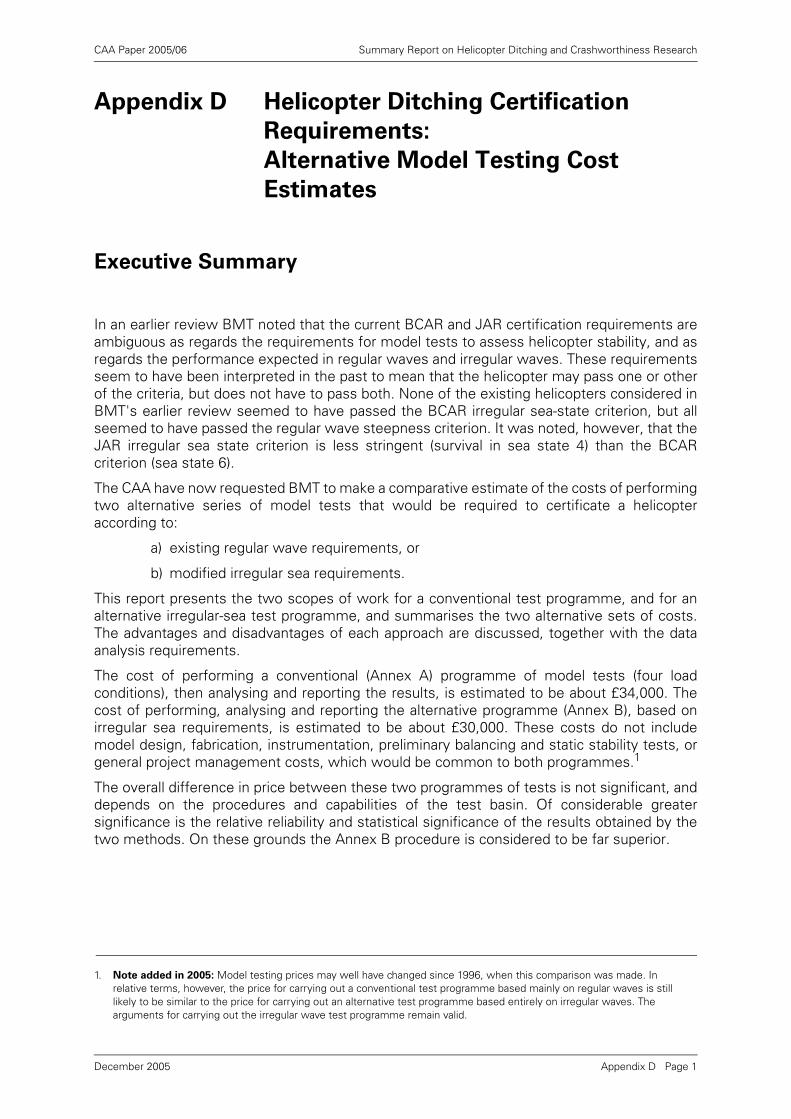
CAA Paper 2005/06 Summary Report on Helicopter Ditching and Crashworthiness Research
Appendix D Helicopter Ditching Certification
Requirements:
Alternative Model Testing Cost
Estimates
Executive Summary
In an earlier review BMT noted that the current BCAR and JAR certification requirements areambiguous as regards the requirements for model tests to assess helicopter stability, and asregards the performance expected in regular waves and irregular waves. These requirementsseem to have been interpreted in the past to mean that the helicopter may pass one or otherof the criteria, but does not have to pass both. None of the existing helicopters considered inBMT's earlier review seemed to have passed the BCAR irregular sea-state criterion, but allseemed to have passed the regular wave steepness criterion. It was noted, however, that theJAR irregular sea state criterion is less stringent (survival in sea state 4) than the BCARcriterion (sea state 6).
The CAA have now requested BMT to make a comparative estimate of the costs of performingtwo alternative series of model tests that would be required to certificate a helicopteraccording to:
a) existing regular wave requirements, or
b) modified irregular sea requirements.
This report presents the two scopes of work for a conventional test programme, and for analternative irregular-sea test programme, and summarises the two alternative sets of costs.The advantages and disadvantages of each approach are discussed, together with the dataanalysis requirements.
The cost of performing a conventional (Annex A) programme of model tests (four loadconditions), then analysing and reporting the results, is estimated to be about £34,000. Thecost of performing, analysing and reporting the alternative programme (Annex B), based onirregular sea requirements, is estimated to be about £30,000. These costs do not includemodel design, fabrication, instrumentation, preliminary balancing and static stability tests, orgeneral project management costs, which would be common to both programmes.1
The overall difference in price between these two programmes of tests is not significant, anddepends on the procedures and capabilities of the test basin. Of considerable greatersignificance is the relative reliability and statistical significance of the results obtained by thetwo methods. On these grounds the Annex B procedure is considered to be far superior.
1. Note added in 2005: Model testing prices may well have changed since 1996, when this comparison was made. In relative terms, however, the price for carrying out a conventional test programme based mainly on regular waves is still likely to be similar to the price for carrying out an alternative test programme based entirely on irregular waves. The arguments for carrying out the irregular wave test programme remain valid.
Appendix D Page 1December 2005
CAA Paper 2005/06 Summary Report on Helicopter Ditching and Crashworthiness Research
1 Introduction
The Civil Aviation Authority (CAA), Safety Regulation Group, have requested BMTFluid Mechanics Limited (BMT) to make a comparative estimate of the costs ofperforming two alternative series of model tests that would be required to certificatea helicopter according to:
a) existing regular wave requirements, or
b) modified irregular sea requirements.
BMT had previously carried out a review of helicopter ditching performance andcertification requirements on behalf of the CAA [1, 2]. BMT noted [1] that the currentCAA certification requirements [3, 4] are ambiguous as regards requirements formodel tests to assess helicopter stability, and as regards the performance expectedin regular waves and irregular waves. These requirements seem to have beeninterpreted in the past to mean that the helicopter may pass one or other of thecriteria, but does not have to pass both. None of the existing helicopters consideredin BMT's review seemed to have passed the BCAR irregular sea-state criterion, butall seemed to have passed the regular wave steepness criterion.
BMT's second report [2] reviewed differences between the British Civil AirworthinessRequirements (BCAR) and the Joint Airworthiness Requirements (JAR) on helicopterditching. This review found an important difference in required survival conditions(sea state 4 specified in the JAR [5, 6], but sea state 6 in the BCAR [3, 4]), althoughboth imply that higher sea states might be appropriate. Both the BCAR and JARrequirements were considered to be ambiguous about the steepness of the wavesto be considered.
BMT considered [1] that the results of regular wave tests may be misleading, and thatan irregular wave criterion is a more realistic measure of the likely actual performanceof the helicopter ditched in the sea. It was further suggested that a minimum modeltesting standard should be considered.
The present report represents the first stage in developing such a standard. It aims toidentify minimum requirements and costs for a programme of helicopter model testsin irregular waves, and compares these with the requirements and costs for aconventional programme of tests performed mainly in regular waves.
1.1 Terms of Reference
BMT's response to CAA's request for a proposal for this work was contained in BMTletter, ref. q94384/sjr/l1, dated 29 April 1996. BMT's scope of work was defined to beas follows:
a) Prepare a specification for a traditional regular wave certification model test.
b) Prepare a specification for an irregular wave certification test to demonstrate an80% probability of remaining upright in sea state 4.
c) Prepare cost estimates for the performance of the two different tests.
d) Prepare a short report summarising the cost elements, and explaining the reasonsfor the main differences (and including the specifications as annexes).
Appendix D Page 2December 2005
CAA Paper 2005/06 Summary Report on Helicopter Ditching and Crashworthiness Research
2 BCAR and JAR Model Testing Requirements
Current CAA requirements for model testing are mainly defined in British CivilAirworthiness Requirement (BCAR) Paper G779 [3]. BMT carried out a detailedreview of these requirements in [1]. The following points are relevant to the presentstudy:
• The craft should remain afloat for the time required for everybody to escape. Thistime should be not less than 5 minutes in severe seas, and an allowance fordamage to the helicopter should be made.
• Satisfactory flotation and trim characteristics are to be demonstrated byinvestigation and model tests, conducted so that the results are valid in the'declared conditions'. Model testing is considered to be compulsory.
• The 'declared conditions' are defined to be those in which compliance with therequirements has been demonstrated. If these are less than those described in theAppendix of [3], they have to be included in the Flight Manual as limitations.
• The standard conditions are defined in the Appendix of [3] as follows:
a) Sea states should cover the range 0 to 6, but with a maximum wave height(usually 1.6 times the significant wave height) of 9.15m. Sea state codes arelisted in Table 1.
b) Individual waves should have height/ length ratios in the range 1:8 for rotorcraftin Group B, and 1:10 for rotorcraft in Group A, for all sea states in (a). The waveheight/ length ratio may be varied with the declared time interval, up to amaximum of 1:12.5 when there is no limit on the declared time interval.
The JAR [6] requires the craft to cope with 'reasonably probable water conditions',and states that sea state 4 may be regarded as representative of reasonably probablewater conditions. Sea state 4 is defined as a moderate sea with significant waveheights of 4 to 8 feet, with a height-to-length ratio of:
• 1:12.5 for Category A rotorcraft,
• 1:10 for Category B rotorcraft, with Category A engine isolation,
• 1:8 for Category B rotorcraft.
As noted in [1, 2], there are a number of ambiguities in both sets of requirements,although a fairly standard interpretation seems to have emerged over the years. Thisforms the basis for the conventional model testing programme described below.
It should be noted that several alternative definitions of sea state codes are incommon use. These definitions differ in terms of the range of significant waveheights contained within each sea state. Defining a wave condition by sea state istherefore ambiguous, and thus not recommended. In order to define a wave conditionunambiguously, the significant wave height, modal (peak) wave period and spectrumshape (e.g. JONSWAP, Pierson Moskowitz) should be defined.
Appendix D Page 3December 2005
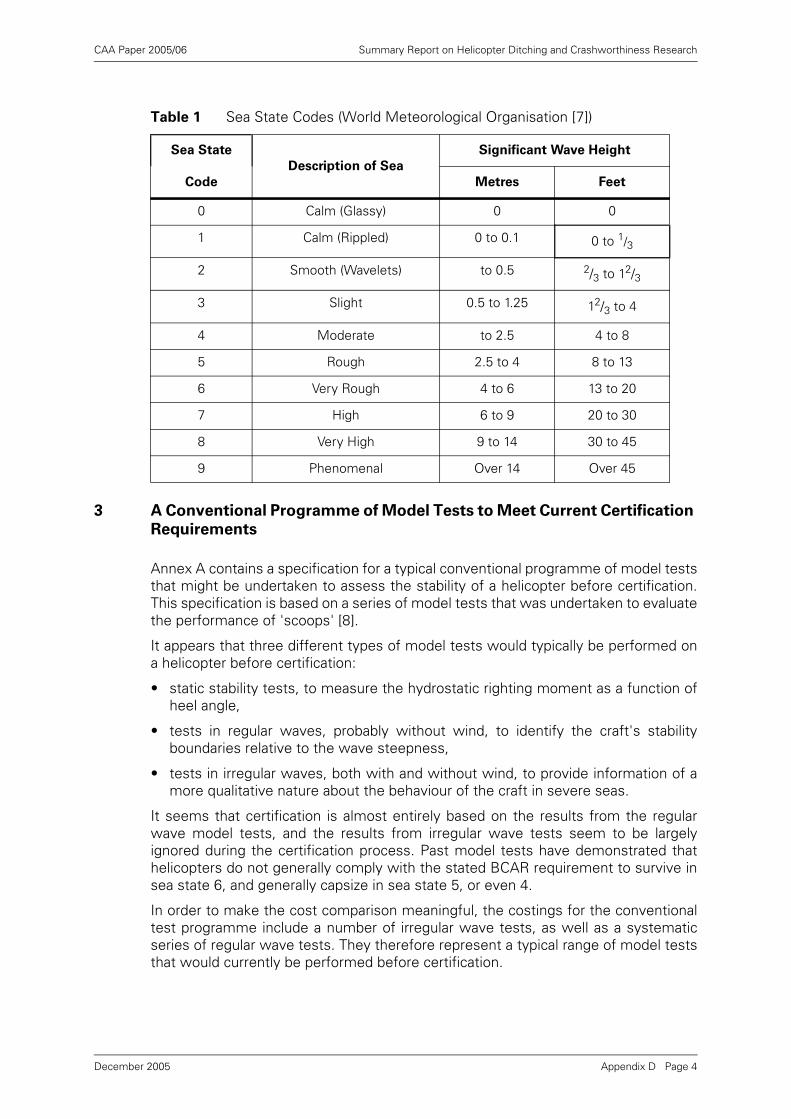
CAA Paper 2005/06 Summary Report on Helicopter Ditching and Crashworthiness Research
3 A Conventional Programme of Model Tests to Meet Current Certification
Requirements
Annex A contains a specification for a typical conventional programme of model teststhat might be undertaken to assess the stability of a helicopter before certification.This specification is based on a series of model tests that was undertaken to evaluatethe performance of 'scoops' [8].
It appears that three different types of model tests would typically be performed ona helicopter before certification:
• static stability tests, to measure the hydrostatic righting moment as a function ofheel angle,
• tests in regular waves, probably without wind, to identify the craft's stabilityboundaries relative to the wave steepness,
• tests in irregular waves, both with and without wind, to provide information of amore qualitative nature about the behaviour of the craft in severe seas.
It seems that certification is almost entirely based on the results from the regularwave model tests, and the results from irregular wave tests seem to be largelyignored during the certification process. Past model tests have demonstrated thathelicopters do not generally comply with the stated BCAR requirement to survive insea state 6, and generally capsize in sea state 5, or even 4.
In order to make the cost comparison meaningful, the costings for the conventionaltest programme include a number of irregular wave tests, as well as a systematicseries of regular wave tests. They therefore represent a typical range of model teststhat would currently be performed before certification.
Table 1 Sea State Codes (World Meteorological Organisation [7])
Sea State
Description of Sea
Significant Wave Height
Code Metres Feet
0 Calm (Glassy) 0 0
1 Calm (Rippled) 0 to 0.1 0 to 1/3
2 Smooth (Wavelets) to 0.5 2/3 to 12/3
3 Slight 0.5 to 1.25 12/3 to 4
4 Moderate to 2.5 4 to 8
5 Rough 2.5 to 4 8 to 13
6 Very Rough 4 to 6 13 to 20
7 High 6 to 9 20 to 30
8 Very High 9 to 14 30 to 45
9 Phenomenal Over 14 Over 45
Appendix D Page 4December 2005
CAA Paper 2005/06 Summary Report on Helicopter Ditching and Crashworthiness Research
3.1 Model
Dynamic similarity is required between the model and full-scale craft. This requiresthe external hull form of the model, together with all significant attached sources ofbuoyancy (e.g. flotation bags) to be geometrically similar to the full-scale helicopter.Any floodable spaces must also have the same scaled internal volume and location.
The total structure mass, centre of gravity and radii of gyration of the model also haveto be dynamically similar to those of the full-scale aircraft.
The model scale has to be chosen in relation to the wave generation capabilities ofthe test basin. The tests are conducted and analysed according to Froude scalinglaws. The model has to be large enough to allow its physical properties to berepresented reasonably accurately, but small enough to allow the largest sea statesto be generated.
It seems to be common practice to build and test two models: a large model at about1:10 scale, tested in moderate sea states, and a small model at about 1:25 scale,tested in very severe sea states. The large model seems to be built mainly for ditchingtests, whereas the smaller model is built specifically for stability tests in higher seastates.
There seems to be little obvious need for testing two models, and no obvious needto test in quite such severe conditions. It is therefore assumed for present purposesthat only one model will be built, at about 1:15 scale. Model-scale waves of significantheight 0.27m then represent full-scale waves with a significant height of 4m (theupper limit for sea state 5), and this should be well within the capability of mostmodern wave basins.
It is assumed that the helicopter will be tested in four conditions: both fully and lightlyloaded, with the helicopter's centre of gravity at both forward and aft positions.
3.2 Static Stability Tests
The helicopter model should first be balanced to obtain the correct mass propertiesin air: the correct total mass, the correct centre of gravity position (x, y and z), and thecorrect radii of gyration in roll, pitch and yaw. Measured and required values shouldthen be tabulated. Normal practice is to balance the model for one load condition andone centre of gravity position, and ballast requirements for the other load conditionand centre of gravity position will then be obtained by calculation.
The helicopter model should then be mounted in a frame, which holds the modelstatically at a range of known heel angles, between the upright and inverted positions,while the hydrostatic righting moment is measured. The model has to be able to trimand heave naturally at every stage during this entire process, so that it remains inhydrostatic equilibrium in these two modes. The heel axis should pass through thecraft's centre of gravity, and the dynamometer must be able to measure both positiveand negative righting moments.
A typical range of tests would cover a range of about 40 heel angles between 0o and360o, for each of two craft loading conditions. The tests may be limited to heel anglesin the range 0o to 180o if the craft is laterally symmetric. All tests should be performedin still water.
The total number of such measurements is therefore 80 (i.e. 40 angles × 2 loadconditions).
Appendix D Page 5December 2005
CAA Paper 2005/06 Summary Report on Helicopter Ditching and Crashworthiness Research
3.2.1 Analysis
The results should be presented in the form of a curve of righting moment againstheel angle, for each load condition.
3.3 Regular Wave Tests
Regular wave tests are usually performed in order to establish the helicopter'sstability boundaries, with respect to limiting values of the wave steepness. BMT hadearlier [1] expressed reservations about whether the results from such tests are likelyto be meaningful. The problem with such tests is that helicopter models normally onlycapsize in breaking waves, and the results from such tests are likely to depend moreon wave basin properties (how quickly waves break as they travel along the tank, andwhere the model is located in the tank) than on the helicopter model's properties.
The present proposal is concerned with comparing established practice, based onregular wave testing, with a possible new procedure based on irregular wave testing.No special precautions will therefore be taken to ensure that the regular waves aremade to break in any particular way, or that relevant physical processes arerepresented.
For present purposes it is assumed that a traditional model test programme wouldcover the following range of conditions:
• about 20 separate regular wave conditions, covering a range of wave heights, withwave steepness values (height/ length) between about 0.08 and 0.13 (assuming aCategory B craft),
• four loading conditions (heavily and lightly loaded, centre of gravity located forwardand aft).
As noted earlier, a small model is often built for testing in very severe sea states. Ifthe requirement is limited to sea state number 5, then the significant wave height willbe at most 4m, and the highest individual wave in this sea state will be less than about6.5m. It is proposed, therefore, that the above 20 tests should cover a range of regularwave heights between about 4m and 7m. This again should be within the capabilityof most modern wave-makers at 1:15 scale, although the range of steepness valuesmay be limited either by the wave-maker software or hardware, or by thehydrodynamic limitations of the basin.
Each test starts with the model floating freely, beam-on to the waves. The model isnot constrained in any way, and is free to turn naturally.
The total number of regular wave tests is therefore 80 (20 wave conditions × 4 loadconditions).
3.3.1 Analysis
A steep regular wave train tends to break down, becoming more irregular andeventually breaking as it travels along the tank. It is not obvious how to characterisethe 'height' of such a breaking wave train, and the relevant height is assumed to bethat of the 1/3 highest waves in the sequence. An average wavelength also has to bedefined, based on the mean zero up-crossing period.
The results should then be presented in the form of a scatter plot, showing the waveheight against wave length for each test, with different symbols used to denotewhether the model remained upright or capsized during a particular test. Constantwave steepness curves (height-to-length ratios 1:8 and 1:10) should be over-plotted,together with stability boundaries separating tests in which the model remainedupright and capsized.
Appendix D Page 6December 2005
CAA Paper 2005/06 Summary Report on Helicopter Ditching and Crashworthiness Research
3.4 Irregular Wave Tests
Current practice is to include a certain number of irregular wave model tests. Thesetests generally seem to be regarded as qualitative in nature: mainly to confirm thehelicopter's behaviour in severe seas. The results are typically presented indescriptive terms, with accompanying photographs, rather than in quantitative terms.It is not obvious how many such tests are performed, and the results seem to belargely ignored in the certification process. Most helicopter models capsize in seastates 5, or even 4, despite current BCAR requirements that they should survive insea states up to 6, unless lower sea states are declared as limitations in theoperations manual. It is understood that no currently certified helicopters contain anysuch stated limitations in their operations manuals. Most craft seem to comply,however, with the lower JAR requirement of survival in sea state 4.
For the purpose of the present comparative study, it will be assumed that thefollowing tests would typically be performed in irregular waves:
• four different steep wave conditions representing sea states 4 and 5 (differentcombinations of significant wave height and zero-crossing period),
• four load conditions (heavily and lightly loaded, centre of gravity located forwardand aft),
• both with and without collinear wind.
The model is initially released beam-on to the wind and waves. It is unconstrained,and can therefore turn until head-on to waves, when it is likely to be more stable.
The waves are chosen from the same range used in the irregular wave testprogramme (Section 4.3 below).
Each test should be of at least 5 minutes (full scale) duration.
The wind speed will be scaled according to Froude's law, in order to ensure thecorrect ratio between wind and wave forces. The physical processes involved in windloading are not correctly represented by Froude's law, however, and the standardapproach adopted in wave basin model tests is to vary the wind speed until the'correct' wind force is applied to the model. The 'correct' forces have to beestablished by comparison with earlier wind tunnel tests. Assuming that wind tunneltest data for the helicopter are not available, the unmodified Froude-scaled windspeed will be used. It seems likely that this same approach has been used in previouscapsize model studies.
The total number of irregular wave tests is 32 (4 wave conditions × 4 load conditions× 2 wind conditions).
3.4.1 Analysis
Minimal analysis will be performed on the results from these tests. Each test isobserved to see whether the model capsizes, and to record its general behaviour. Thetest is also recorded on video and still photographs.
4 An Alternative Programme of Testing Based on Irregular Waves
Annex B contains a specification for a model testing programme, based on irregularwaves, that might be undertaken as an alternative to the conventional programmedescribed in Section 3. The objectives of the new test programme would be generallythe same as the conventional programme, but the changes are intended to meet thecriticisms in [1, 2].
Appendix D Page 7December 2005
CAA Paper 2005/06 Summary Report on Helicopter Ditching and Crashworthiness Research
As noted above, current certification seems to be based mainly on the results fromregular wave model tests. BMT had earlier [1, 2] observed that, in general, helicoptermodels only capsize when these regular waves break, and expressed the view thatthe capsize boundaries measured in such tests may be more a measure of the wavebreaking limits of the test basin than a meaningful measure of the helicopter'sstability.
BMT sees no role for any regular wave model tests in the following alternative testprogramme. This test programme is based entirely on irregular wave tests, andshould be regarded as the minimum necessary to gain certification underrequirements consistent with BMT's recommendations [1, 2].
4.1 Improvements Suggested in Earlier BMT Report
BMT's earlier report [1] first asked whether the helicopter should be assumed to bedamaged during the ditching process. This is clearly only a matter of model designand construction, and does not affect the way in which the tests are conducted. Forpresent purposes, therefore, it is assumed that the model is in the same condition asfor conventional tests (either intact or damaged, as considered appropriate).
BMT's report [1] put forward two alternative options:
• Option 1: retain current definitions of limiting conditions, but frame these in a lessambiguous way,
• Option 2: move to a risk-based approach, where the requirement is todemonstrate an adequately low overall risk of capsize.
Option 2 would have many implications for other areas of CAA certification, and maybe considered appropriate in the longer term. Option 1 could be adopted much morequickly, and would be less controversial. Option 1 has therefore been chosen as thebasis for the present proposed work programme.
BMT then proposed [1] the following changes to the criteria:
a) To base the criteria on irregular wave model tests.
b) To define the irregular wave sea states in terms of their significant wave heights,mean zero up-crossing (or peak) spectral wave periods and spectrum shapes.
c) To define an adequately low risk of capsize in the five-minute exposure period.
d) To provide a list of limiting sea states in which the designer must demonstrate anadequately low risk of capsize.
The following test programme is based exclusively on tests in irregular waves, and isbased on achieving at least 80% probability of survival in sea state 4 (see Table 1) forat least five minutes, with additional tests to determine whether the craft will alsosurvive in sea state 5. These sea states are defined in terms of ranges of significantwave height, spectral peak period and spectral shape.
There is no longer any requirement to demonstrate survival in steep individual waves.It is sufficient to achieve a sufficiently low risk of capsize in sea state 4, which shouldcontain a realistic number of steep and breaking individual waves.
Different model testing establishments have different procedures for generatingirregular wave sequences and spectra. Some of these procedures are likely to bemore appropriate for helicopter stability tests than others. Considerations affectingthe choice of test procedure have already been reviewed in an earlier BMT report [9],and are reproduced below in Annex C.
Appendix D Page 8December 2005
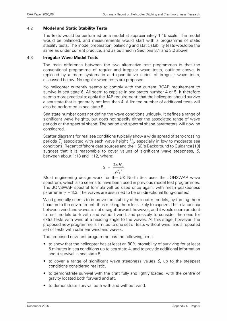
CAA Paper 2005/06 Summary Report on Helicopter Ditching and Crashworthiness Research
4.2 Model and Static Stability Tests
The tests would be performed on a model at approximately 1:15 scale. The modelwould be balanced, and measurements would start with a programme of staticstability tests. The model preparation, balancing and static stability tests would be thesame as under current practice, and as outlined in Sections 3.1 and 3.2 above.
4.3 Irregular Wave Model Tests
The main difference between the two alternative test programmes is that theconventional programme of regular and irregular wave tests, outlined above, isreplaced by a more systematic and quantitative series of irregular wave tests,discussed below. No regular wave tests are proposed.
No helicopter currently seems to comply with the current BCAR requirement tosurvive in sea state 6. All seem to capsize in sea states number 4 or 5. It thereforeseems more practical to apply the JAR requirement: that the helicopter should survivea sea state that is generally not less than 4. A limited number of additional tests willalso be performed in sea state 5.
Sea state number does not define the wave conditions uniquely. It defines a range ofsignificant wave heights, but does not specify either the associated range of waveperiods or the spectral shape. The period and spectral shape parameters will now beconsidered.
Scatter diagrams for real sea conditions typically show a wide spread of zero-crossingperiods Tz associated with each wave height Hs, especially in low to moderate seaconditions. Recent offshore data sources and the HSE's Background to Guidance [10]suggest that it is reasonable to cover values of significant wave steepness, S,between about 1:18 and 1:12, where:
Most engineering design work for the UK North Sea uses the JONSWAP wavespectrum, which also seems to have been used in previous model test programmes.The JONSWAP spectral formula will be used once again, with mean peakednessparameter = 3.3. The waves are assumed to be uni-directional (long-crested).
Wind generally seems to improve the stability of helicopter models, by turning themhead-on to the environment, thus making them less likely to capsize. The relationshipbetween wind and waves is not straightforward, however, and it would seem prudentto test models both with and without wind, and possibly to consider the need forextra tests with wind at a heading angle to the waves. At this stage, however, theproposed new programme is limited to one set of tests without wind, and a repeatedset of tests with collinear wind and waves.
The proposed new test programme has the following aims:
• to show that the helicopter has at least an 80% probability of surviving for at least5 minutes in sea conditions up to sea state 4, and to provide additional informationabout survival in sea state 5,
• to cover a range of significant wave steepness values S, up to the steepestconditions considered realistic,
• to demonstrate survival with the craft fully and lightly loaded, with the centre ofgravity located both forward and aft,
• to demonstrate survival both with and without wind.
2
2
z
s
TgH
Sπ
=
γ
Appendix D Page 9December 2005
CAA Paper 2005/06 Summary Report on Helicopter Ditching and Crashworthiness Research
The test programme therefore covers the following range of conditions:
• a matrix of about twelve sea conditions (four significant wave heights and threesignificant wave steepness values), representing sea states 4 and 5,
• four helicopter load conditions (fully and lightly loaded, centre of gravity locatedforward and aft),
• tests repeated both with and without wind, from the same direction as the waves.
The wind speed will once again be scaled according to Froude's law, noting thereservations expressed in Section 3.4.
There are a number of ways in which the tests might be performed in order to achievea target of 80% probability of survival for at least 5 minutes, and several possible waysin which this requirement might be interpreted.
4.3.1 Approach A: Separate Five-Minute Tests
The most obvious approach would be to carry out individual five-minute tests, andrepeat these several times. Different combinations of randomly-selected wave phaseangles would be selected for each repeat test, in order to ensure independentsamples from the distribution of all possible realisations of the sea state.
The probability of capsize Pc5 in a five-minute period may then be estimated verysimply from the ratio:
This ratio can be estimated more accurately as the number of repeat tests isincreased. It seems likely that a minimum of about ten such repeat tests will beneeded in order to obtain a reasonably reliable estimate of the 80% exceedancevalue.
4.3.2 Approach B: Single Continuous Test
The total time in the test basin can be reduced significantly if the test runs are joinedtogether. Waves are then run continuously, only stopping when the level of 'noise' inthe basin reaches an unacceptable level, or when a capsize occurs. Each successivefive-minute (full scale) segment from the record is then treated as if it is a separatemodel test. The test run has to be re-started every time a capsize occurs, with adifferent random realisation of the sea state, until the required total number of five-minute test runs has been completed.
This raises an important question about the way in which the tests are conducted:whether the model should be left entirely free, or restrained in order to prevent itturning into the wind and waves. Previous model test results suggest that wind oftenhas a stabilising influence, turning the model head into the waves. Current practice istherefore to test a freely-floating model, which is initially placed beam-on to thewaves, but is then allowed to turn naturally in the wind and waves.
If several individual five-minute (full scale) tests are replaced by a single extendedtest, a free-floating model would quickly turn into the weather, and would be relativelystable for the remainder of the test period, thus giving an optimistic view of thehelicopter's stability. If, on the other hand, the model is constrained by lines, so thatit remains beam-on to the waves, this will prevent it taking up its more stable heading,and will therefore give a pessimistic view of its stability. The advantages of thisapproach, however, are that the test can be extended as long as necessary, thusminimising tank time, and the results are likely to be more repeatable and steady-state in character.
testsofnumbertotalcapsizesofnumber
5 =cP
Appendix D Page 10December 2005
CAA Paper 2005/06 Summary Report on Helicopter Ditching and Crashworthiness Research
BMT's present view is that the benefits of testing with a constrained model outweighthe disadvantages, and these tests will still give a fair view of the craft's stability inwind and waves. The results are likely to be slightly more conservative, however, thanunder current testing regimes. The following test programme is therefore based onusing a constrained model, that is kept permanently beam-on to the waves.
A test of five minutes duration at full scale will take about 77 seconds at 1:15 modelscale. The present costing is based on Approach B, where all ten repeat tests takeplace during a single extended run, except in cases where the run has to be re-startedafter a capsize. It should be possible to complete about ten such tests in a single runlasting about 15 minutes.
The total number of extended irregular wave runs is therefore assumed to be 96(12 sea states × 4 load conditions × 2 wind conditions), with re-starts as necessary incases where the model capsizes.
4.3.3 Analysis
Results will be presented in the form of capsize boundaries on the (Hs, Tz) scatterdiagram. The results from each extended test run will provide a single estimate of theprobability of capsize Pc5, and this will be used to identify a single point on the scatterplot of Hs against Tz. Different symbols will be used to denote conditions in which Pc5is less than or greater than 0.8. (Different symbols may also be used to denoteconditions in which Pc5 exceeds other values, such as 0.7 or 0.9, if these are also ofinterest.). Curves of constant values of significant steepness should be over-plotted,and a boundary curve inserted between points which lie above and below the 80%exceedance data.
5 Comparative Costs
The following costs are intended for guidance, and are for comparative purposes only.The costs of testing a particular model will vary according to individual circumstances,detailed test requirements, and on the pricing policy of the individual test basin. Thefollowing costs and comments are based on information provided by the HaslarHydrodynamic Test Centre, Gosport, Hampshire, UK.
The following costs cover model test set-up, the model tests themselves, dataanalysis and reporting only. They do not cover model design, fabrication andinstrumentation, model balancing, initial static stability tests or general projectmanagement costs, because these items would be common to both types of testprogramme.
5.1 Tests According to Existing Standard Procedures
The scope of work for this conventional programme of model tests is summarised inAnnex A, and includes the following items:
• Set-up on facility, with video and two wave gauges. Calibrate waves. Set up windfans, and calibrate the required conditions.
• Conduct regular wave tests, light and heavy load conditions, centre of gravitylocated forward and aft. Model free to drift. Total of 80 runs of 5 minutes (full scale)duration.
• Conduct irregular wave tests, light and heavy load conditions, centre of gravitylocated forward and aft, with and without wind. Model free to drift. Total of 32 runsof 5 minutes (full scale) duration.
Appendix D Page 11December 2005
CAA Paper 2005/06 Summary Report on Helicopter Ditching and Crashworthiness Research
• Data analysis and reporting.
5.2 Tests According to Modified Procedures
The scope of work for this modified programme of model tests is summarised inAnnex B, and includes the following items:
• Set-up on facility, with video and two wave gauges. Calibrate waves. Set up windfans, and calibrate the required conditions. Set up mooring system.
• Conduct irregular wave tests, light and heavy load conditions, centre of gravitylocated forward and aft, with and without wind. Model restrained in beam seas.Total of 96 runs of 15 minutes (model scale) duration.
• Data analysis and reporting.
5.3 Discussion
It is estimated that both test programmes will involve the same number of actual daysof testing (i.e. about 10). The man-power requirements under the Annex B procedureare lower, however, because the model is restrained by lines. This means that thecarriage does not have to move, and there is no need to provide for fending the modeloff the tank wall.
It should be noted that a significant part of the total set-up cost relates to theinstallation and calibration of wind fans. The costs of providing wind fans aresomewhat uncertain, because precise requirements will depend on circumstances. Ithas been assumed that the test basin has enough existing fans to cover the requiredtest area, and that the fans are capable of achieving the required maximum windspeed. The model is restrained under the Annex B procedure, and so the fans will nothave to cover such a wide area of the tank. This factor has slightly reduced the set-upcosts compared to the Annex A procedure, offsetting the extra cost of setting up themooring system.
The analysis of results from the Annex B tests is more complex, and will takemarginally longer (although a bespoke analysis program could be written to minimisethese costs). Reporting effort will be similar in both cases.
6 Conclusions
BMT have made comparative estimates of the costs of performing two alternativeseries of model tests that would be required to certificate a helicopter according to:
a) existing regular wave requirements, or
b) modified irregular sea requirements.
Scopes of work for a conventional test programme and an alternative irregular-seatest programme have been developed, and the corresponding costs have beensummarised.
The cost of performing a conventional (Annex A) programme of model tests (four loadconditions), then analysing and reporting the results, is estimated to be about£34,000. The cost of performing, analysing and reporting the alternative programme
Total cost for tests as per Annex A: £34,000
Total cost for tests as per Annex B: £30,000
Appendix D Page 12December 2005
CAA Paper 2005/06 Summary Report on Helicopter Ditching and Crashworthiness Research
(Annex B), based on irregular sea requirements, is estimated to be about £30,000.These costs do not include model design, fabrication, instrumentation, preliminarybalancing and static stability tests, or general project management costs, whichwould be common to both programmes.
The overall difference in price between these two programmes of tests is notsignificant, and depends on the procedures and capabilities of the test basin. Ofconsiderable greater significance is the relative reliability and statistical significance ofthe results obtained by the two methods. On these grounds the Annex B procedureis considered to be far superior.
7 References
[1] BMT Offshore Limited, Review of helicopter ditching certification requirements,Report 2, Project no. 44011/00, 1993.
[2] BMT Offshore Limited, Helicopter ditching: JAR certification requirements,Report 3, Project no. 44035/00, 1995.
[3] Civil Aviation Authority, British Civil Airworthiness Requirements, Paper no.G779, 7 October 1985.
[4] Civil Aviation Authority, British Civil Airworthiness Requirements, Sub-sectionG4 - Design and Construction, Chapter G4-10, Emergency Alighting on Water, 20January 1975.
[5] JAR 29.801 from Joint Aviation Requirements JAR-29 Large Rotorcraft, CivilAviation Authority (on behalf of the Joint Aviation Authorities Committee), 5November 1993.
[6] Advisory Circular No. 29-2A, Change 2, Certification of Transport CategoryRotorcraft, Federal Aviation Administration, 24 September 1991.
[7] Meteorological Office, Ships' Code and Decode Book, ref. Met.O. 509, HMSO,1968.
[8] British Hovercraft Corporation Limited, Helicopter flotation stability - aninvestigation into the effect of fitting water scoops onto emergency floats,Report no. X/O/3257, 1986.
[9] BMT Offshore Limited, Review of helicopter ditching performance, Report 1,Project no. 44011/00, 1993.
[10] Institute of Oceanographic Sciences, Estimating wave climate parameters forengineering applications, Department of Energy report no. OTH 86 228, HMSO,1986.
Appendix D Page 13December 2005
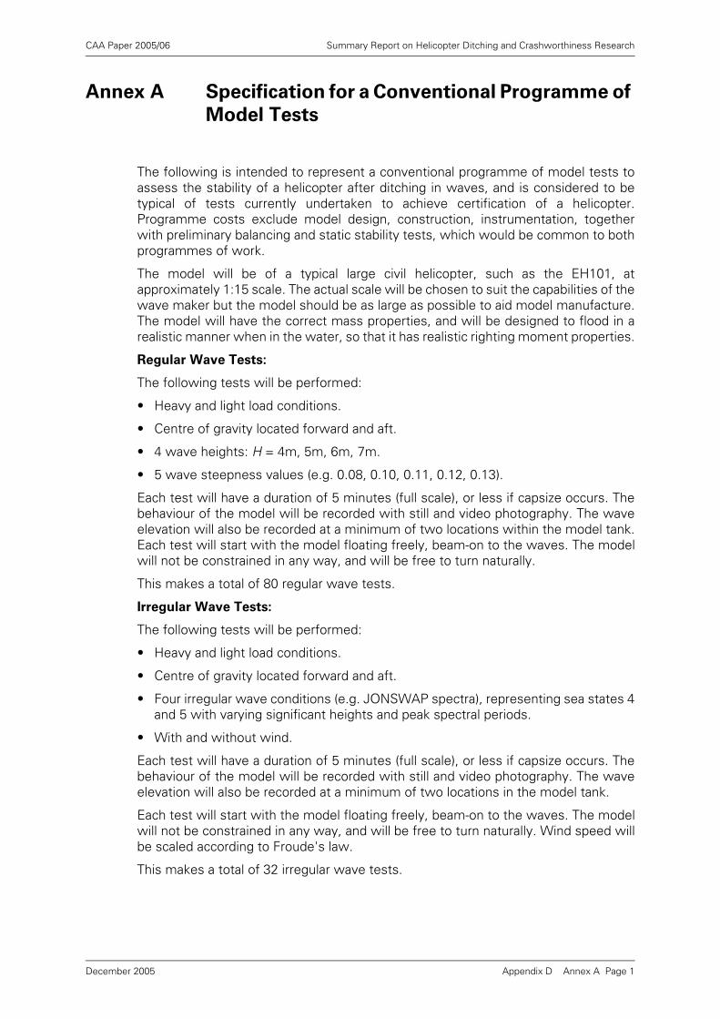
CAA Paper 2005/06 Summary Report on Helicopter Ditching and Crashworthiness Research
Annex A Specification for a Conventional Programme of
Model Tests
The following is intended to represent a conventional programme of model tests toassess the stability of a helicopter after ditching in waves, and is considered to betypical of tests currently undertaken to achieve certification of a helicopter.Programme costs exclude model design, construction, instrumentation, togetherwith preliminary balancing and static stability tests, which would be common to bothprogrammes of work.
The model will be of a typical large civil helicopter, such as the EH101, atapproximately 1:15 scale. The actual scale will be chosen to suit the capabilities of thewave maker but the model should be as large as possible to aid model manufacture.The model will have the correct mass properties, and will be designed to flood in arealistic manner when in the water, so that it has realistic righting moment properties.
Regular Wave Tests:
The following tests will be performed:
• Heavy and light load conditions.
• Centre of gravity located forward and aft.
• 4 wave heights: H = 4m, 5m, 6m, 7m.
• 5 wave steepness values (e.g. 0.08, 0.10, 0.11, 0.12, 0.13).
Each test will have a duration of 5 minutes (full scale), or less if capsize occurs. Thebehaviour of the model will be recorded with still and video photography. The waveelevation will also be recorded at a minimum of two locations within the model tank.Each test will start with the model floating freely, beam-on to the waves. The modelwill not be constrained in any way, and will be free to turn naturally.
This makes a total of 80 regular wave tests.
Irregular Wave Tests:
The following tests will be performed:
• Heavy and light load conditions.
• Centre of gravity located forward and aft.
• Four irregular wave conditions (e.g. JONSWAP spectra), representing sea states 4and 5 with varying significant heights and peak spectral periods.
• With and without wind.
Each test will have a duration of 5 minutes (full scale), or less if capsize occurs. Thebehaviour of the model will be recorded with still and video photography. The waveelevation will also be recorded at a minimum of two locations in the model tank.
Each test will start with the model floating freely, beam-on to the waves. The modelwill not be constrained in any way, and will be free to turn naturally. Wind speed willbe scaled according to Froude's law.
This makes a total of 32 irregular wave tests.
Appendix D Annex A Page 1December 2005
CAA Paper 2005/06 Summary Report on Helicopter Ditching and Crashworthiness Research
Analysis
Results from the regular wave tests will be presented in the form of individual points,which identify whether capsize occurred, together with capsize boundaries, on aplotting of wave height against wavelength (or wave period).
Each irregular wave test will be observed to see whether capsize occurs, and torecord the model's general behaviour. The test will be recorded using still and videophotography.
Appendix D Annex A Page 2December 2005
CAA Paper 2005/06 Summary Report on Helicopter Ditching and Crashworthiness Research
Appendix D Annex B Page 1
Annex B Specification for an Alternative Programme of
Model Tests
The following alternative programme of model tests is intended to assess the stabilityof a helicopter after ditching in waves, on the basis of a programme of systematicirregular-wave model tests only. Programme costs exclude model design,construction, instrumentation, together with preliminary balancing and static stabilitytests, which would be common to both programmes of work.
The model will be of a typical large civil helicopter, such as the EH101, atapproximately 1:15 scale. The actual scale will be chosen to suit the capabilities of thewave maker but the model should be as large as possible to aid model manufacture.The model will have the correct mass properties, and will be designed to flood in arealistic manner when in the water, so that it has realistic righting moment properties.
Irregular Wave Tests:
The following tests will be performed:
• Heavy and light load conditions.
• Centre of gravity located forward and aft.
• Twelve irregular wave conditions (e.g. JONSWAP spectra) representing sea states4 and 5 with varying significant heights and peak spectral periods.
• With and without wind.
Each test will have a minimum duration of 15 minutes (model scale). It thereforemeets the requirements for the single long continuous test described in Section4.3.2: Approach B, with about ten different short realisations of the sea state run incontinuous succession. When capsize occurs, the run will be halted, the modelreturned to the upright condition, and the run continued. The behaviour of the modelwill be recorded with still and video photography. The wave elevation will be recordedat a minimum of two locations in the model tank.
Each test will start with the model floating beam-on to the waves. The model will beconstrained by light lines, so that it remains permanently beam-on to the waves. Windspeed will be scaled according to Froude's law.
This makes at total of 96 extended irregular wave tests, with re-starts as necessary.
Analysis
The probability of capsize in each sea state within each five-minute period will becalculated by taking the ratio of the total number of observed capsizes divided by thetotal number of five-minute (full scale) segments represented in each extended testrun. The results will then be presented graphically as points on a scatter diagram ofsignificant wave height and peak spectral period, using different symbols to denotedifferent capsize probability ranges. Capsize boundaries will also be shown.
Records will also be made using still and video photography.
December 2005
CAA Paper 2005/06 Summary Report on Helicopter Ditching and Crashworthiness Research
Annex C Model Testing Considerations
The following text is reproduced from BMT's report [9].
1 Introduction
Physical model tests are often the only way of handling complicated dynamicproblems such as the capsize of helicopters in waves. Models constructed with dueregard to the necessary physical similarity and mass/inertia properties can give arealistic qualitative and quantitative impression of the way in which the full scalehelicopter will behave. The tests can be particularly impressive to the layman whosees what appears to be a true representation of reality (particularly when filmed, andslowed down to simulated 'real-time').
However, such tests do present a number of real difficulties which must beconsidered when such tests are designed or the results from them interpreted.
The main difficulties when considered in the context of helicopters are:
• The construction of accurate models (accurate in terms of shape, floodability,mass, inertia, etc).
• The generation of appropriate and repeatable wave conditions.
• The conduct of tests in these waves in a controlled and repeatable manner.
2 Model Construction
It is important that models used in this type of testing are statically and dynamicallysimilar to the full scale helicopter.
Static similarity involves ensuring that the external shape and dimensions areaccurately represented on the model. When the model is going to be permitted toflood through open doors it is also necessary to ensure that the internal voids areproperly modelled. This latter can be quite difficult to do precisely owing to the needfor very thin walls, and the many internal details (passenger seats etc.).
The model must also have the correct weight and centre of gravity location. This canbe quite difficult to arrange (particularly for small models when it is sometimesdifficult to make the model light enough). Obtaining the appropriate centre of gravitylocation involves balancing the model and adding ballast weights until the correct CGlocation is achieved.
Dynamic similarity involves ensuring that the inertia of the models in the threerotational axes is correct. The most important in the context of capsize is obviouslythe roll inertia or radius of gyration.
It is usual in wave model test reports to list all the static and dynamic properties ofthe model both as 'desired' and 'obtained' so that the reader can judge the accuracyof the modelling. In the case of the BHC model test reports [C1] and [C2], informationon the means of balancing the model and achieving the desired properties is rathersketchy, and tables showing full scale and model properties do not seem to be 'asmeasured' properties of the model, but rather just desired values scaled down fromfull scale.
Appendix D Annex C Page 1December 2005
CAA Paper 2005/06 Summary Report on Helicopter Ditching and Crashworthiness Research
In the context of helicopters there are some specific modelling problems:
• How to model the interior spaces when water is permitted to flood in and washthrough the cabin.
• How to model the rotor. The prototype rotor assemblies are quite flexible, and it isnot immediately clear how the inertia of the rotor influences the total inertia of thehelicopter at wave frequencies. The rotor tips are also likely to touch the watersurface in extreme conditions and it is not clear how this should be modelled. (It isnoticeable that most of the helicopter models tested by BHC did not have rotorsfitted, but in some cases used a mast with a weight on the top to help obtain therequired total CG and inertias.)
3 Wave Conditions
3.1 Regular Waves
'Regular' waves (the reason for the quote marks will become apparent later) areintended to be regular in terms of the wave amplitude and frequency, the wavemakerpaddle normally moving with a sinusoidal movement.
Until the late 60's almost all wave model tests were performed in regular wavesbecause this was the only wave generation technology available. All realised thatthese regular waves were a very poor model of the real waves experienced in theocean, but if one was able to assume linearity of response, harmonic or Fourieranalysis provided ways of interpreting this information to predict the behaviour inirregular seas.
In addition to not being representative of real ocean waves the apparent simplicity ofsinusoidal regular waves is, to some extent, illusory. Only the least steep (small waveheight compared with wave length) approximate to sinusoidal shape. The steeperthese waves become, the less sinusoidal they are - the peaks get more sharp and thetroughs flatten. Somewhere between a wave length/wave height of 10 - 7 thesewaves also break.
In longer model basins it also becomes apparent that such 'regular' waves do notpropagate unchanged down the tank. Depending on their steepness, and the distancethey have travelled, and the purity of the initial wave form, these waves degrade andchange shape as they propagate. Eventually they become quite irregular and break.This means that the shape and properties of the wave are different in different partsof the tank, and also tend to change with time as reflections and other 'noise' build-up in the tank accelerate the degradation process.
Furthermore, waves steeper than 1:10 will often break as they are generated at thewavemaker paddle.
Once breaking is occurring in a 'regular' wave train, an energy conversion process isoccurring that ensures that the wave cannot continue to propagate with the sameshape and regular properties. It can no longer be a regular wave.
It is clear from the above that tests performed in steep regular waves are fraught withdifficulties. The wave shape changes with position in the tank and with elapsed time,and one run will usually be different from the next. This presents particular problemsfor the testing of a free-drifting model as the helicopter model will tend to drift downthe tank from a region of smooth regular waves into a region of steadily increasingirregularity and wave breaking. (The model cannot be constrained to remain in thesame place, as these constraining forces would have a major effect on its behaviour.)
Appendix D Annex C Page 2December 2005
CAA Paper 2005/06 Summary Report on Helicopter Ditching and Crashworthiness Research
These factors were well-understood by those who performed the helicopter modeltests in steep 'regular' waves. It is clear from the work reported that no capsizesoccur unless the vehicle is hit by a breaking wave. Thus 'regular' waves in this contexthave really been used as a way of making breaking waves - which are inevitablyirregular by nature.
It is understood that the wave height, wavelength and steepness were estimated asbest as possible for an individual wave that capsized (or failed to capsize) the model.This was in itself very difficult in practice as the model was not necessarily alongsidea wave probe at the moment of interest.
3.2 Irregular Waves
The use of 'more realistic' irregular waves has been on the increase since the 60's.Understanding of the ocean environment was improving, and later the availability ofcheap computer technology and servo-controlled wavemakers started to impact onthe science, and permitted more sophisticated control of wavemakers.
Early irregular wavemakers were electro-mechanical, driven by a variable speedelectric motor via an eccentric crank, where the speed of the motor was controlled bysome kind of programming device (often a punched card). In these systems theirregular sequence was usually quite short (say 100 waves) before the programrepeated, and this type of control made it difficult to produce waves with a spectrumshape and Gaussian randomness (or pseudo-randomness) that was representative ofthe real ocean.
Later wavemakers, actuated by hydraulic servo systems or linear electrical actuatorsand controlled by computer, solved these problems and made it possible to generatemore or less infinite sequences of pseudo-random waves with the desired spectraland statistical properties. More recently this technology has been extended to multi-directional irregular waves in some tanks.
A good quality irregular wavemaker makes it possible to generate irregular waves ina closely controlled and repeatable fashion that is a good representation of a givensea-state. In fact wavemaker technology today is capable of generating waves tomuch closer tolerances than the ocean environment is generally understood.
The strategy adopted in the irregular wave test is rather different from a that used ina regular wave test. The usual policy is to set a given sea-state (usually defined interms of a significant wave height, mean period and spectrum shape) and record thebehaviour of the vessel under test for a long period of time (often about 3 hours full-scale time). The reason for the long run times is that the results of the test can onlyreally be interpreted properly in a statistical fashion if there are a lot of waves. Inprinciple, a helicopter ditching test could be run on many occasions in different time-history realisations of the same sea-state, and an accurate determination made of theprobability of capsize in any period of time. In practice there are some difficulties withthis approach.
The free drifting nature of the model means that eventually the model will drift downthe tank and the run must be stopped. Also when capsize occurs, the test mustobviously be halted and the model recovered.
In addition to this inherent difficulty it is unfortunate that the model tests conductedin irregular waves described in [1] and [2] have been performed using an electro-mechanical wavemaker of the early type. This has lead to very poor spectral shapingand very short run sequences.
All that is known from such a test is whether the helicopter capsized or not. If it did,then there is still no information about the probability of capsize in a given period of
Appendix D Annex C Page 3December 2005
CAA Paper 2005/06 Summary Report on Helicopter Ditching and Crashworthiness Research
exposure. If the size of the wave that capsized the helicopter were known, then itmight be possible to calculate the probability of this wave, but this has not beenrecorded.
Similarly, if a helicopter remained upright through a sequence of 100 waves (about 10minutes full-scale time) then there is nothing to say that a 101st wave would not havecapsized it. A detailed statistical analysis of the 100 wave heights experienced wouldreveal whether these 100 waves represented a typical distribution of heights, butagain this information is not believed to be available for the tests concerned.
3.3 An Ideal Helicopter Capsize Model Test
Given that the requirement for a ditched helicopter is to remain upright long enoughfor crew and passengers to make a safe evacuation to the life rafts, the realrequirement for a helicopter model test is to demonstrate that the probability ofcapsize within a given short period (say 5 or 10 minutes) is adequately low.
The only way of demonstrating this in a physical model test is to run a large series ofrealistic irregular wave conditions and record the mean frequency of capsizes thatoccur. This will enable the probability of capsize to be estimated. Alternatively, if thewave height and period characteristics which cause capsize can be recorded in eachcase (difficult because of the drifting position of the helicopter model), then theprobability of meeting this wave can be estimated and the probability of capsizearrived at in this way.
This implies that a large number of long tests must be performed in a long tank withgood wave generation properties.
4 Further References
[1] BHC Draft Report No X/O/3282, Nov 1985, Study of Float Positioning.
[2] BHC Report No X/O/3257, April 1986, Study of Fitting Scoops to EmergencyFloats.
Appendix D Annex C Page 4December 2005
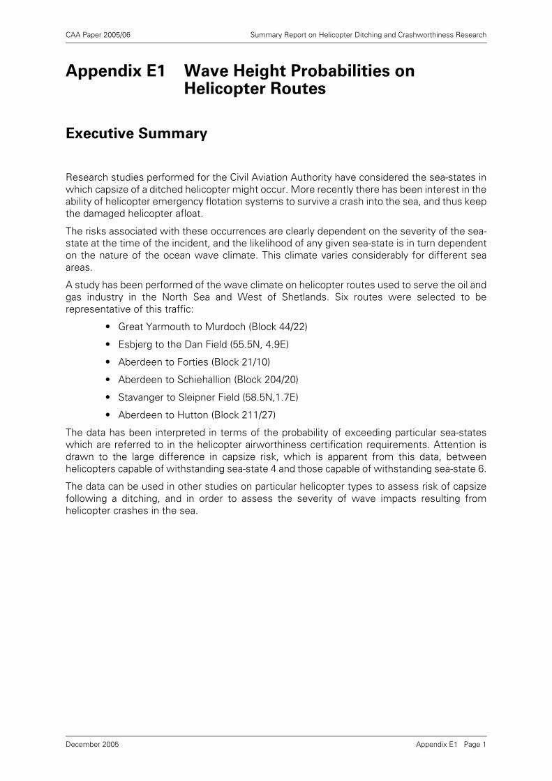
CAA Paper 2005/06 Summary Report on Helicopter Ditching and Crashworthiness Research
Appendix E1 Wave Height Probabilities on Helicopter Routes
Executive Summary
Research studies performed for the Civil Aviation Authority have considered the sea-states inwhich capsize of a ditched helicopter might occur. More recently there has been interest in theability of helicopter emergency flotation systems to survive a crash into the sea, and thus keepthe damaged helicopter afloat.
The risks associated with these occurrences are clearly dependent on the severity of the sea-state at the time of the incident, and the likelihood of any given sea-state is in turn dependenton the nature of the ocean wave climate. This climate varies considerably for different seaareas.
A study has been performed of the wave climate on helicopter routes used to serve the oil andgas industry in the North Sea and West of Shetlands. Six routes were selected to berepresentative of this traffic:
• Great Yarmouth to Murdoch (Block 44/22)
• Esbjerg to the Dan Field (55.5N, 4.9E)
• Aberdeen to Forties (Block 21/10)
• Aberdeen to Schiehallion (Block 204/20)
• Stavanger to Sleipner Field (58.5N,1.7E)
• Aberdeen to Hutton (Block 211/27)
The data has been interpreted in terms of the probability of exceeding particular sea-stateswhich are referred to in the helicopter airworthiness certification requirements. Attention isdrawn to the large difference in capsize risk, which is apparent from this data, betweenhelicopters capable of withstanding sea-state 4 and those capable of withstanding sea-state 6.
The data can be used in other studies on particular helicopter types to assess risk of capsizefollowing a ditching, and in order to assess the severity of wave impacts resulting fromhelicopter crashes in the sea.
Appendix E1 Page 1December 2005
CAA Paper 2005/06 Summary Report on Helicopter Ditching and Crashworthiness Research
1 Introduction
Research studies performed for the Civil Aviation Authority have considered the sea-states in which capsize of a ditched helicopter might occur [1]. More recently therehas been interest in the ability of helicopter emergency flotation systems to survive acrash into the sea, and thus keep the damaged helicopter afloat [2].
The consequences of these occurrences are clearly dependent on the severity of thesea-state at the time of the incident, and the likelihood of any given sea-state is in turndependent on the nature of the ocean wave climate. This climate varies considerablyfor different sea areas.
The objective of this study was to establish the wave climate along a representativeselection of the main helicopter routes used to service the offshore oil and gasindustry in the North Sea and West of Shetlands.
BMT Fluid Mechanics Limited (BMT) submitted a proposal [3] which suggested theuse of archived data from the UK Meteorological Office wave forecasting model.1 Sixhelicopter routes were chosen, and grid points were selected from the forecastingmodel which represented these routes. The work, was performed under the CAAcontract [4].
Data was obtained from the forecasting model on the frequencies of occurrence ofsignificant wave height, zero crossing period and wind speed, although the work ofthis present study considered only the significant wave height. The height frequencydata was converted to probabilities of exceeding sea-states in the range 3 - 7.
These probabilities have been interpreted in terms of the risk of exceeding sea-statesspecified in airworthiness certification requirements.
2 Definitions
2.1 The Routes
It was considered that the main part of the population of helicopter flights in supportof the oil and gas industry in the North Sea and West of Shetlands could becharacterised by six routes as follows:
1. Note added in 2005: This study was undertaken in 1997 using archived wave forecast data. If a similar study were to be performed today, the preferred wave data sources would be either satellite measurements or wave hindcast data sets such as NEXT or NEXTRA. Use of these later data sources would not significantly affect the outcome of the study, however.
A Aberdeen to Schiehallion (Block 204/20)
B Aberdeen to Hutton (Block 211/27)
C Aberdeen to Forties (Block 21/10)
D Great Yarmouth to Murdoch (Block 44/22)
E Stavanger to Sleipner Field (58.5N,1.7E)
F Esbjerg to the Dan Field (55.5N, 4.9E)
Appendix E1 Page 2December 2005
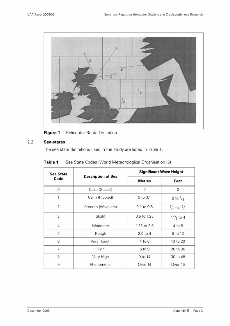
CAA Paper 2005/06 Summary Report on Helicopter Ditching and Crashworthiness Research
2.2 Sea-states
The sea state definitions used in the study are listed in Table 1.
Figure 1 Helicopter Route Definition
Table 1 Sea State Codes (World Meteorological Organisation [5)
Sea State
CodeDescription of Sea
Significant Wave Height
Metres Feet
0 Calm (Glassy) 0 0
1 Calm (Rippled) 0 to 0.1 0 to 1/3
2 Smooth (Wavelets) 0.1 to 0.5 2/3 to 12/3
3 Slight 0.5 to 1.25 12/3 to 4
4 Moderate 1.25 to 2.5 4 to 8
5 Rough 2.5 to 4 8 to 13
6 Very Rough 4 to 6 13 to 20
7 High 6 to 9 20 to 30
8 Very High 9 to 14 30 to 45
9 Phenomenal Over 14 Over 45
Appendix E1 Page 3December 2005
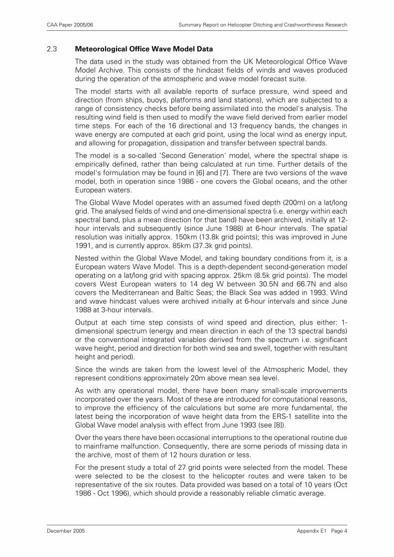
CAA Paper 2005/06 Summary Report on Helicopter Ditching and Crashworthiness Research
2.3 Meteorological Office Wave Model Data
The data used in the study was obtained from the UK Meteorological Office WaveModel Archive. This consists of the hindcast fields of winds and waves producedduring the operation of the atmospheric and wave model forecast suite.
The model starts with all available reports of surface pressure, wind speed anddirection (from ships, buoys, platforms and land stations), which are subjected to arange of consistency checks before being assimilated into the model's analysis. Theresulting wind field is then used to modify the wave field derived from earlier modeltime steps. For each of the 16 directional and 13 frequency bands, the changes inwave energy are computed at each grid point, using the local wind as energy input,and allowing for propagation, dissipation and transfer between spectral bands.
The model is a so-called 'Second Generation' model, where the spectral shape isempirically defined, rather than being calculated at run time. Further details of themodel's formulation may be found in [6] and [7]. There are two versions of the wavemodel, both in operation since 1986 - one covers the Global oceans, and the otherEuropean waters.
The Global Wave Model operates with an assumed fixed depth (200m) on a lat/longgrid. The analysed fields of wind and one-dimensional spectra (i.e. energy within eachspectral band, plus a mean direction for that band) have been archived, initially at 12-hour intervals and subsequently (since June 1988) at 6-hour intervals. The spatialresolution was initially approx. 150km (13.8k grid points); this was improved in June1991, and is currently approx. 85km (37.3k grid points).
Nested within the Global Wave Model, and taking boundary conditions from it, is aEuropean waters Wave Model. This is a depth-dependent second-generation modeloperating on a lat/long grid with spacing approx. 25km (8.5k grid points). The modelcovers West European waters to 14 deg W between 30.5N and 66.7N and alsocovers the Mediterranean and Baltic Seas; the Black Sea was added in 1993. Windand wave hindcast values were archived initially at 6-hour intervals and since June1988 at 3-hour intervals.
Output at each time step consists of wind speed and direction, plus either: 1-dimensional spectrum (energy and mean direction in each of the 13 spectral bands)or the conventional integrated variables derived from the spectrum i.e. significantwave height, period and direction for both wind sea and swell, together with resultantheight and period).
Since the winds are taken from the lowest level of the Atmospheric Model, theyrepresent conditions approximately 20m above mean sea level.
As with any operational model, there have been many small-scale improvementsincorporated over the years. Most of these are introduced for computational reasons,to improve the efficiency of the calculations but some are more fundamental, thelatest being the incorporation of wave height data from the ERS-1 satellite into theGlobal Wave model analysis with effect from June 1993 (see [8]).
Over the years there have been occasional interruptions to the operational routine dueto mainframe malfunction. Consequently, there are some periods of missing data inthe archive, most of them of 12 hours duration or less.
For the present study a total of 27 grid points were selected from the model. Thesewere selected to be the closest to the helicopter routes and were taken to berepresentative of the six routes. Data provided was based on a total of 10 years (Oct1986 - Oct 1996), which should provide a reasonably reliable climatic average.
Appendix E1 Page 4December 2005
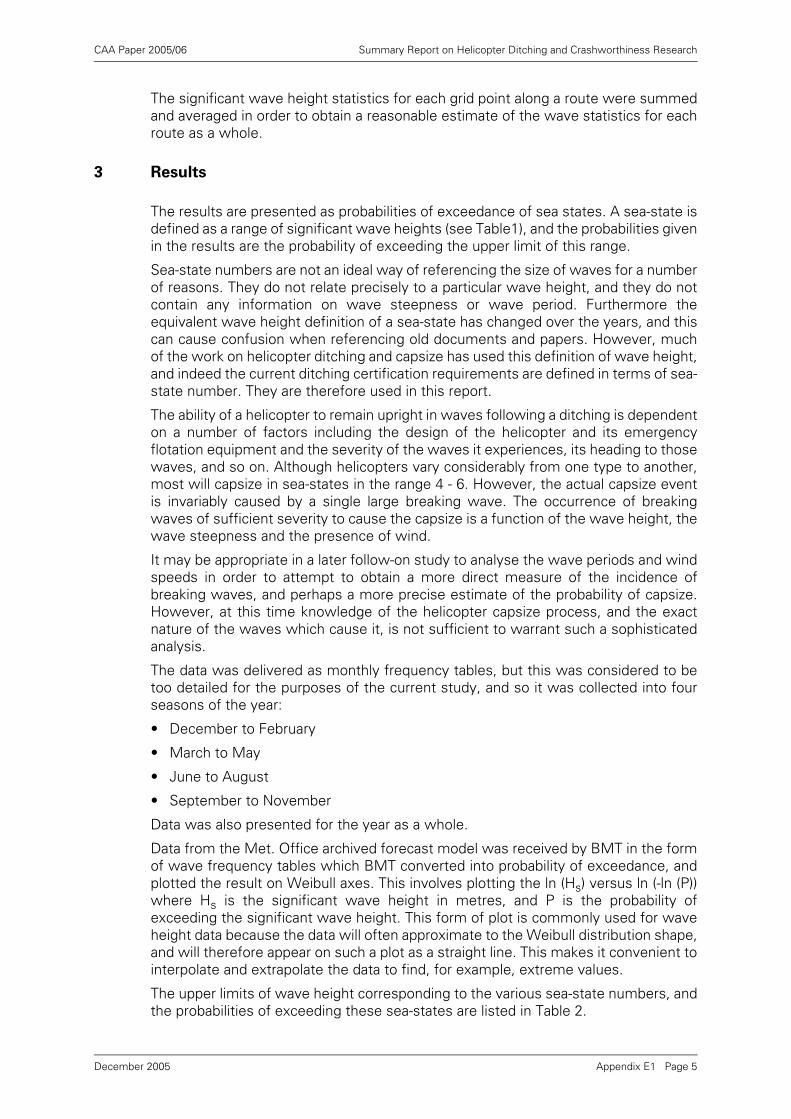
CAA Paper 2005/06 Summary Report on Helicopter Ditching and Crashworthiness Research
The significant wave height statistics for each grid point along a route were summedand averaged in order to obtain a reasonable estimate of the wave statistics for eachroute as a whole.
3 Results
The results are presented as probabilities of exceedance of sea states. A sea-state isdefined as a range of significant wave heights (see Table1), and the probabilities givenin the results are the probability of exceeding the upper limit of this range.
Sea-state numbers are not an ideal way of referencing the size of waves for a numberof reasons. They do not relate precisely to a particular wave height, and they do notcontain any information on wave steepness or wave period. Furthermore theequivalent wave height definition of a sea-state has changed over the years, and thiscan cause confusion when referencing old documents and papers. However, muchof the work on helicopter ditching and capsize has used this definition of wave height,and indeed the current ditching certification requirements are defined in terms of sea-state number. They are therefore used in this report.
The ability of a helicopter to remain upright in waves following a ditching is dependenton a number of factors including the design of the helicopter and its emergencyflotation equipment and the severity of the waves it experiences, its heading to thosewaves, and so on. Although helicopters vary considerably from one type to another,most will capsize in sea-states in the range 4 - 6. However, the actual capsize eventis invariably caused by a single large breaking wave. The occurrence of breakingwaves of sufficient severity to cause the capsize is a function of the wave height, thewave steepness and the presence of wind.
It may be appropriate in a later follow-on study to analyse the wave periods and windspeeds in order to attempt to obtain a more direct measure of the incidence ofbreaking waves, and perhaps a more precise estimate of the probability of capsize.However, at this time knowledge of the helicopter capsize process, and the exactnature of the waves which cause it, is not sufficient to warrant such a sophisticatedanalysis.
The data was delivered as monthly frequency tables, but this was considered to betoo detailed for the purposes of the current study, and so it was collected into fourseasons of the year:
• December to February
• March to May
• June to August
• September to November
Data was also presented for the year as a whole.
Data from the Met. Office archived forecast model was received by BMT in the formof wave frequency tables which BMT converted into probability of exceedance, andplotted the result on Weibull axes. This involves plotting the ln (Hs) versus ln (-ln (P))where Hs is the significant wave height in metres, and P is the probability ofexceeding the significant wave height. This form of plot is commonly used for waveheight data because the data will often approximate to the Weibull distribution shape,and will therefore appear on such a plot as a straight line. This makes it convenient tointerpolate and extrapolate the data to find, for example, extreme values.
The upper limits of wave height corresponding to the various sea-state numbers, andthe probabilities of exceeding these sea-states are listed in Table 2.
Appendix E1 Page 5December 2005
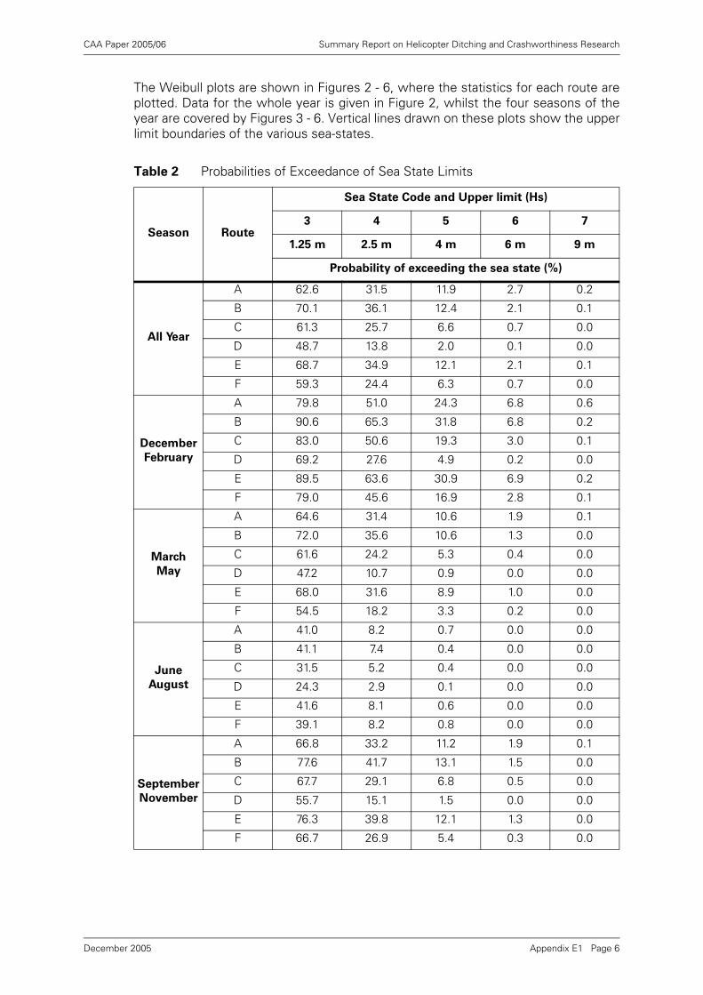
CAA Paper 2005/06 Summary Report on Helicopter Ditching and Crashworthiness Research
The Weibull plots are shown in Figures 2 - 6, where the statistics for each route areplotted. Data for the whole year is given in Figure 2, whilst the four seasons of theyear are covered by Figures 3 - 6. Vertical lines drawn on these plots show the upperlimit boundaries of the various sea-states.
Table 2 Probabilities of Exceedance of Sea State Limits
Season Route
Sea State Code and Upper limit (Hs)
3 4 5 6 7
1.25 m 2.5 m 4 m 6 m 9 m
Probability of exceeding the sea state (%)
All Year
A 62.6 31.5 11.9 2.7 0.2
B 70.1 36.1 12.4 2.1 0.1
C 61.3 25.7 6.6 0.7 0.0
D 48.7 13.8 2.0 0.1 0.0
E 68.7 34.9 12.1 2.1 0.1
F 59.3 24.4 6.3 0.7 0.0
December
February
A 79.8 51.0 24.3 6.8 0.6
B 90.6 65.3 31.8 6.8 0.2
C 83.0 50.6 19.3 3.0 0.1
D 69.2 27.6 4.9 0.2 0.0
E 89.5 63.6 30.9 6.9 0.2
F 79.0 45.6 16.9 2.8 0.1
March
May
A 64.6 31.4 10.6 1.9 0.1
B 72.0 35.6 10.6 1.3 0.0
C 61.6 24.2 5.3 0.4 0.0
D 47.2 10.7 0.9 0.0 0.0
E 68.0 31.6 8.9 1.0 0.0
F 54.5 18.2 3.3 0.2 0.0
June
August
A 41.0 8.2 0.7 0.0 0.0
B 41.1 7.4 0.4 0.0 0.0
C 31.5 5.2 0.4 0.0 0.0
D 24.3 2.9 0.1 0.0 0.0
E 41.6 8.1 0.6 0.0 0.0
F 39.1 8.2 0.8 0.0 0.0
September
November
A 66.8 33.2 11.2 1.9 0.1
B 77.6 41.7 13.1 1.5 0.0
C 67.7 29.1 6.8 0.5 0.0
D 55.7 15.1 1.5 0.0 0.0
E 76.3 39.8 12.1 1.3 0.0
F 66.7 26.9 5.4 0.3 0.0
Appendix E1 Page 6December 2005
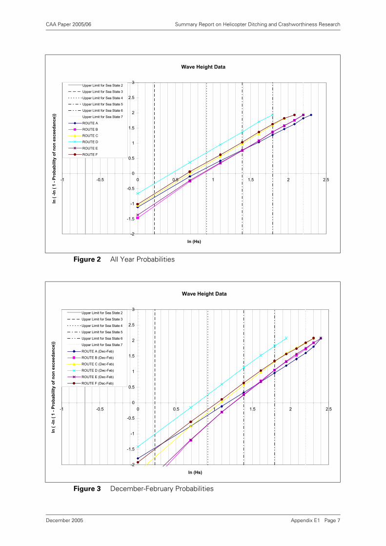
CAA Paper 2005/06 Summary Report on Helicopter Ditching and Crashworthiness Research
Figure 2 All Year Probabilities
Figure 3 December-February Probabilities
Wave Height Data
-2
-1.5
-1
-0.5
0
0.5
1
1.5
2
2.5
3
-1 -0.5 0 0.5 1 1.5 2 2.5
ln (Hs)
ln (
-ln
( 1
- P
rob
ab
ilit
y o
f n
on
ex
ce
ed
an
ce
))
Upper Limit for Sea State 2
Upper Limit for Sea State 3
Upper Limit for Sea State 4
Upper Limit for Sea State 5
Upper Limit for Sea State 6
Upper Limit for Sea State 7
ROUTE A
ROUTE B
ROUTE C
ROUTE D
ROUTE E
ROUTE F
Wave Height Data
-2
-1.5
-1
-0.5
0
0.5
1
1.5
2
2.5
3
-1 -0.5 0 0.5 1 1.5 2 2.5
ln (Hs)
ln (
-ln
( 1
- P
rob
ab
ilit
y o
f n
on
ex
ce
ed
an
ce
))
Upper Limit for Sea State 2
Upper Limit for Sea State 3
Upper Limit for Sea State 4
Upper Limit for Sea State 5
Upper Limit for Sea State 6
Upper Limit for Sea State 7
ROUTE A (Dec-Feb)
ROUTE B (Dec-Feb)
ROUTE C (Dec-Feb)
ROUTE D (Dec-Feb)
ROUTE E (Dec-Feb)
ROUTE F (Dec-Feb)
Appendix E1 Page 7December 2005
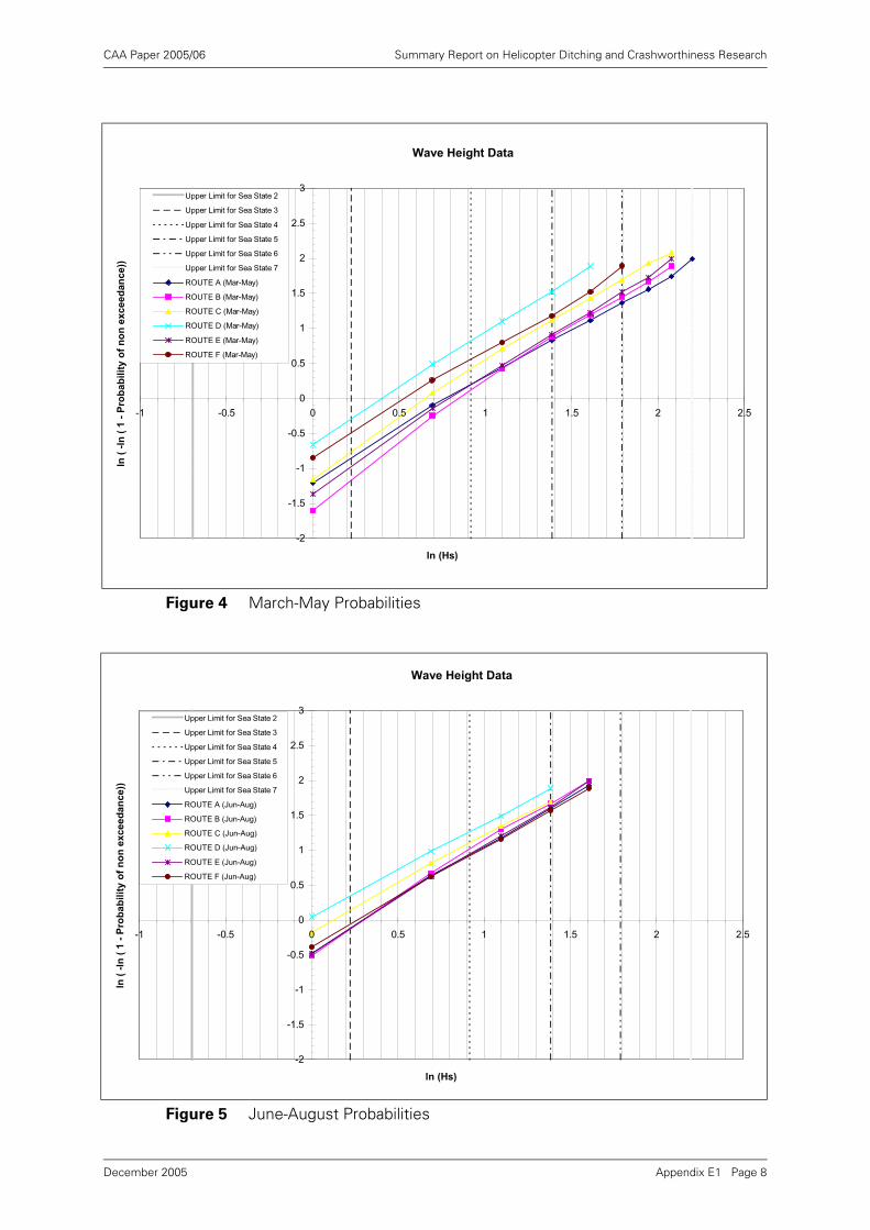
CAA Paper 2005/06 Summary Report on Helicopter Ditching and Crashworthiness Research
Figure 4 March-May Probabilities
Figure 5 June-August Probabilities
Wave Height Data
-2
-1.5
-1
-0.5
0
0.5
1
1.5
2
2.5
3
-1 -0.5 0 0.5 1 1.5 2 2.5
ln (Hs)
ln (
-ln
( 1
- P
rob
ab
ilit
y o
f n
on
ex
ce
ed
an
ce
))
Upper Limit for Sea State 2
Upper Limit for Sea State 3
Upper Limit for Sea State 4
Upper Limit for Sea State 5
Upper Limit for Sea State 6
Upper Limit for Sea State 7
ROUTE A (Mar-May)
ROUTE B (Mar-May)
ROUTE C (Mar-May)
ROUTE D (Mar-May)
ROUTE E (Mar-May)
ROUTE F (Mar-May)
Wave Height Data
-2
-1.5
-1
-0.5
0
0.5
1
1.5
2
2.5
3
-1 -0.5 0 0.5 1 1.5 2 2.5
ln (Hs)
ln (
-ln
( 1
- P
rob
ab
ilit
y o
f n
on
ex
ce
ed
an
ce
))
Upper Limit for Sea State 2
Upper Limit for Sea State 3
Upper Limit for Sea State 4
Upper Limit for Sea State 5
Upper Limit for Sea State 6
Upper Limit for Sea State 7
ROUTE A (Jun-Aug)
ROUTE B (Jun-Aug)
ROUTE C (Jun-Aug)
ROUTE D (Jun-Aug)
ROUTE E (Jun-Aug)
ROUTE F (Jun-Aug)
Appendix E1 Page 8December 2005
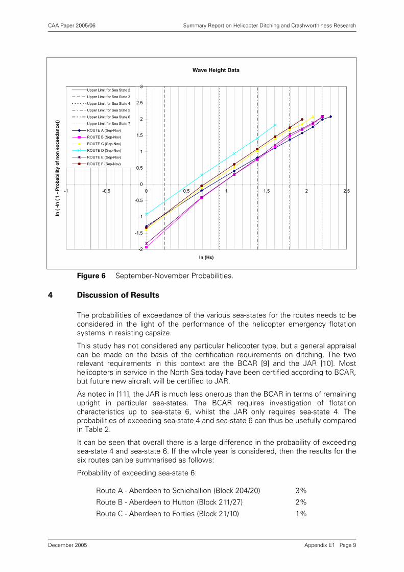
CAA Paper 2005/06 Summary Report on Helicopter Ditching and Crashworthiness Research
4 Discussion of Results
The probabilities of exceedance of the various sea-states for the routes needs to beconsidered in the light of the performance of the helicopter emergency flotationsystems in resisting capsize.
This study has not considered any particular helicopter type, but a general appraisalcan be made on the basis of the certification requirements on ditching. The tworelevant requirements in this context are the BCAR [9] and the JAR [10]. Mosthelicopters in service in the North Sea today have been certified according to BCAR,but future new aircraft will be certified to JAR.
As noted in [11], the JAR is much less onerous than the BCAR in terms of remainingupright in particular sea-states. The BCAR requires investigation of flotationcharacteristics up to sea-state 6, whilst the JAR only requires sea-state 4. Theprobabilities of exceeding sea-state 4 and sea-state 6 can thus be usefully comparedin Table 2.
It can be seen that overall there is a large difference in the probability of exceedingsea-state 4 and sea-state 6. If the whole year is considered, then the results for thesix routes can be summarised as follows:
Probability of exceeding sea-state 6:
Figure 6 September-November Probabilities.
Route A - Aberdeen to Schiehallion (Block 204/20) 3%
Route B - Aberdeen to Hutton (Block 211/27) 2%
Route C - Aberdeen to Forties (Block 21/10) 1%
Wave Height Data
-2
-1.5
-1
-0.5
0
0.5
1
1.5
2
2.5
3
-1 -0.5 0 0.5 1 1.5 2 2.5
ln (Hs)
ln (
-ln
( 1
- P
rob
ab
ilit
y o
f n
on
ex
ce
ed
an
ce
))
Upper Limit for Sea State 2
Upper Limit for Sea State 3
Upper Limit for Sea State 4
Upper Limit for Sea State 5
Upper Limit for Sea State 6
Upper Limit for Sea State 7
ROUTE A (Sep-Nov)
ROUTE B (Sep-Nov)
ROUTE C (Sep-Nov)
ROUTE D (Sep-Nov)
ROUTE E (Sep-Nov)
ROUTE F (Sep-Nov)
Appendix E1 Page 9December 2005
CAA Paper 2005/06 Summary Report on Helicopter Ditching and Crashworthiness Research
Probability of exceeding sea-state 4:
In the northern North Sea (e.g. Route B) sea-state 4 is exceeded for 36% of the time.Thus a helicopter certified to sea-state 4 ditching on this route at a random time duringthe year would have a 1 in 3 chance of capsize. If, however, the helicopter wascapable of fulfilling a more onerous requirement of sea-state 6, then there would onlybe a 2% (or 1 in 50 chance) of experiencing a capsize. This dramatically demonstratesthe large difference in risk levels represented by different certification requirements.
The seasonal variations can also be seen from Table 2. Probabilities of Exceedance ofSea-state Limits. Taking route B as an example, the probability of exceedance of sea-state 4 varies from 65% in the winter months down to 7% in the summer months.Sea-state 6 is exceeded 7% of the time in the winter months and not at all in thesummer months.
The climatic variation between the different routes is very much as expected. Themost benign route is D from Great Yarmouth to the southern basin fields. The mostsevere are those in the North.
5 Summary and Conclusions
5.1 Summary
This project has established the wave climate along the main helicopter routes usedto service the offshore oil and gas industry in the North Sea and West of Shetlands.
The results of this study provide information on the probability of experiencing orexceeding a range of significant wave heights or sea states on various helicopterroutes in the North Sea and West of Shetlands.
These data can be interpreted in terms of risk of capsize of helicopters which haveditched on the surface of the sea.
They can also be used as part of studies of crashworthiness where the sea-state isone of the factors which may influence the severity of the wave impact, and hencethe ability of the helicopter to remain afloat after the incident.
It was not part of the scope of the study to compare the risk of capsize for variousindividual helicopter types, but general conclusions may be drawn in relation to thecertification requirements relating to ditching.
Route D - Great Yarmouth to Murdoch (Block 44/22) >0%
Route E - Stavanger to Sleipner Field (58.5N,1.7E) 2%
Route F - Esbjerg to the Dan Field (55.5N, 4.9E) 1%
Route A - Aberdeen to Schiehallion (Block 204/20) 32%
Route B - Aberdeen to Hutton (Block 211/27) 36%
Route C - Aberdeen to Forties (Block 21/10) 26%
Route D - Great Yarmouth to Murdoch (Block 44/22) 14%
Route E - Stavanger to Sleipner Field (58.5N,1.7E) 35%
Route F - Esbjerg to the Dan Field (55.5N, 4.9E) 24%
Appendix E1 Page 10December 2005
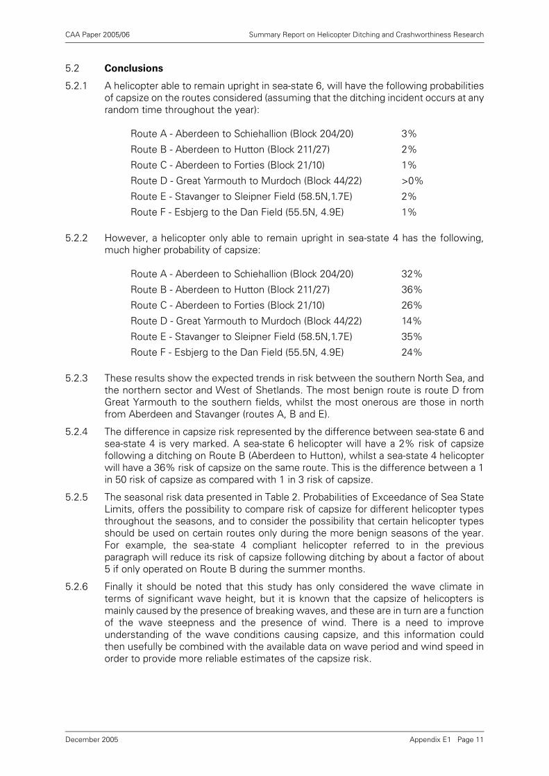
CAA Paper 2005/06 Summary Report on Helicopter Ditching and Crashworthiness Research
5.2 Conclusions
5.2.1 A helicopter able to remain upright in sea-state 6, will have the following probabilitiesof capsize on the routes considered (assuming that the ditching incident occurs at anyrandom time throughout the year):
5.2.2 However, a helicopter only able to remain upright in sea-state 4 has the following,much higher probability of capsize:
5.2.3 These results show the expected trends in risk between the southern North Sea, andthe northern sector and West of Shetlands. The most benign route is route D fromGreat Yarmouth to the southern fields, whilst the most onerous are those in northfrom Aberdeen and Stavanger (routes A, B and E).
5.2.4 The difference in capsize risk represented by the difference between sea-state 6 andsea-state 4 is very marked. A sea-state 6 helicopter will have a 2% risk of capsizefollowing a ditching on Route B (Aberdeen to Hutton), whilst a sea-state 4 helicopterwill have a 36% risk of capsize on the same route. This is the difference between a 1in 50 risk of capsize as compared with 1 in 3 risk of capsize.
5.2.5 The seasonal risk data presented in Table 2. Probabilities of Exceedance of Sea StateLimits, offers the possibility to compare risk of capsize for different helicopter typesthroughout the seasons, and to consider the possibility that certain helicopter typesshould be used on certain routes only during the more benign seasons of the year.For example, the sea-state 4 compliant helicopter referred to in the previousparagraph will reduce its risk of capsize following ditching by about a factor of about5 if only operated on Route B during the summer months.
5.2.6 Finally it should be noted that this study has only considered the wave climate interms of significant wave height, but it is known that the capsize of helicopters ismainly caused by the presence of breaking waves, and these are in turn are a functionof the wave steepness and the presence of wind. There is a need to improveunderstanding of the wave conditions causing capsize, and this information couldthen usefully be combined with the available data on wave period and wind speed inorder to provide more reliable estimates of the capsize risk.
Route A - Aberdeen to Schiehallion (Block 204/20) 3%
Route B - Aberdeen to Hutton (Block 211/27) 2%
Route C - Aberdeen to Forties (Block 21/10) 1%
Route D - Great Yarmouth to Murdoch (Block 44/22) >0%
Route E - Stavanger to Sleipner Field (58.5N,1.7E) 2%
Route F - Esbjerg to the Dan Field (55.5N, 4.9E) 1%
Route A - Aberdeen to Schiehallion (Block 204/20) 32%
Route B - Aberdeen to Hutton (Block 211/27) 36%
Route C - Aberdeen to Forties (Block 21/10) 26%
Route D - Great Yarmouth to Murdoch (Block 44/22) 14%
Route E - Stavanger to Sleipner Field (58.5N,1.7E) 35%
Route F - Esbjerg to the Dan Field (55.5N, 4.9E) 24%
Appendix E1 Page 11December 2005
CAA Paper 2005/06 Summary Report on Helicopter Ditching and Crashworthiness Research
6 References
[1] Review of helicopter ditching performance, BMT Offshore Ltd., Report onProject 44011/00 for the Civil Aviation Authority. Report 1 Release 2, July 1993.
[2] Report of the Review of Helicopter Offshore Safety and Survival, Civil AviationAuthority, CAP 641, February 1995.
[3] BMT Fluid Mechanics Limited Proposal No. Q94434_2, 1st October 1996,
[4] CAA Contract 7D/S/1096/3.
[5] Ships' Code and Decode Book, Meteorological Office, ref. Met.O. 509, HMSO,1968.
[6] A wave prediction system for real-time sea state forecasting, Q J R Meteorol Soc109 pp 393-416, Golding, B (1983).
[7] Sea surface wave and storm surge models, Meteorol Mag 114 pp 234-241,Francis, PE (1985).
[8] Preliminary assessment and use of ERS-1 altimeter wave data, J Atmos &Ocean Tech 11 pp 1370-1380, Foreman, SJ, Holt, MW & Kelsall, S (1994).
[9] British Civil Airworthiness Requirements, Civil Aviation Authority, Paper G779,7th October 1985.
[10] JAR 29.801 from Joint Aviation Requirements JAR-29 large Rotorcraft, CivilAviation Authority (on behalf of the Joint Aviation Authorities Committee), 5thNovember 1993.
[11] Helicopter Ditching JAR Certification Requirements, BMT Fluid MechanicsLimited Report 44035 Report 3 Release 2, 28th November 1995.
Appendix E1 Page 12December 2005
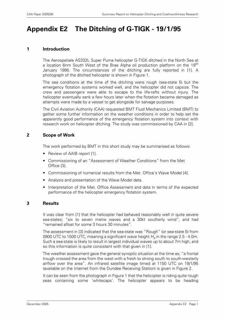
CAA Paper 2005/06 Summary Report on Helicopter Ditching and Crashworthiness Research
Appendix E2 The Ditching of G-TIGK - 19/1/95
1 Introduction
The Aerospatiale AS332L Super Puma helicopter G-TIGK ditched in the North Sea ata location 6nm South West of the Brae Alpha oil production platform on the 19th
January 1995. The circumstances of the ditching are fully reported in [1]. Aphotograph of the ditched helicopter is shown in Figure 1.
The sea conditions at the time of the ditching were rough (sea-state 5) but theemergency flotation systems worked well, and the helicopter did not capsize. Thecrew and passengers were able to escape to the life-rafts without injury. Thehelicopter eventually sank a few hours later when the flotation became damaged asattempts were made by a vessel to get alongside for salvage purposes.
The Civil Aviation Authority (CAA) requested BMT Fluid Mechanics Limited (BMT) togather some further information on the weather conditions in order to help set theapparently good performance of the emergency flotation system into context withresearch work on helicopter ditching. The study was commissioned by CAA in [2].
2 Scope of Work
The work performed by BMT in this short study may be summarised as follows:
• Review of AAIB report [1].
• Commissioning of an “Assessment of Weather Conditions” from the Met Office [3].
• Commissioning of numerical results from the Met. Office's Wave Model [4].
• Analysis and presentation of the Wave Model data.
• Interpretation of the Met. Office Assessment and data in terms of the expectedperformance of the helicopter emergency flotation system.
3 Results
It was clear from [1] that the helicopter had behaved reasonably well in quite severesea-states; “six to seven metre waves and a 30kt southerly wind”, and had“remained afloat for some 3 hours 30 minutes”.
The assessment in [3] indicated that the sea-state was “Rough” (or sea-state 5) from0900 UTC to 1500 UTC, meaning a significant wave height Hs in the range 2.5 - 4.0m.Such a sea-state is likely to result in largest individual waves up to about 7m high, andso this information is quite consistent with that given in [1].
The weather assessment gave the general synoptic situation at the time as; “a frontaltrough crossed the area from the west with a fresh to strong south to south-westerlyairflow over the area”. An infrared satellite image timed at 1150 UTC on 19/1/95(available on the Internet from the Dundee Receiving Station) is given in Figure 2.
It can be seen from the photograph in Figure 1 that the helicopter is riding quite roughseas containing some 'whitecaps'. The helicopter appears to be heading
Appendix E2 Page 1December 2005
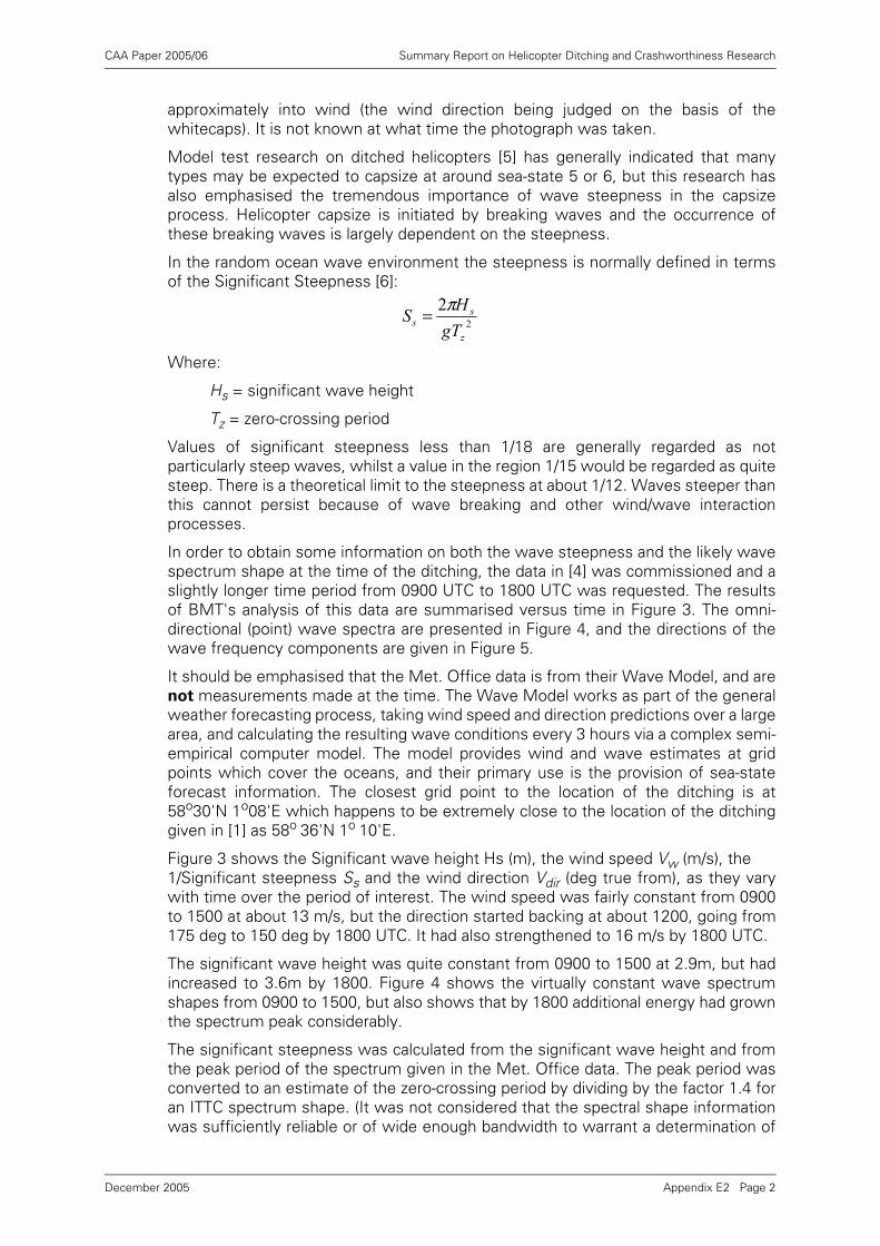
CAA Paper 2005/06 Summary Report on Helicopter Ditching and Crashworthiness Research
approximately into wind (the wind direction being judged on the basis of thewhitecaps). It is not known at what time the photograph was taken.
Model test research on ditched helicopters [5] has generally indicated that manytypes may be expected to capsize at around sea-state 5 or 6, but this research hasalso emphasised the tremendous importance of wave steepness in the capsizeprocess. Helicopter capsize is initiated by breaking waves and the occurrence ofthese breaking waves is largely dependent on the steepness.
In the random ocean wave environment the steepness is normally defined in termsof the Significant Steepness [6]:
Where:
Hs = significant wave height
Tz = zero-crossing period
Values of significant steepness less than 1/18 are generally regarded as notparticularly steep waves, whilst a value in the region 1/15 would be regarded as quitesteep. There is a theoretical limit to the steepness at about 1/12. Waves steeper thanthis cannot persist because of wave breaking and other wind/wave interactionprocesses.
In order to obtain some information on both the wave steepness and the likely wavespectrum shape at the time of the ditching, the data in [4] was commissioned and aslightly longer time period from 0900 UTC to 1800 UTC was requested. The resultsof BMT's analysis of this data are summarised versus time in Figure 3. The omni-directional (point) wave spectra are presented in Figure 4, and the directions of thewave frequency components are given in Figure 5.
It should be emphasised that the Met. Office data is from their Wave Model, and arenot measurements made at the time. The Wave Model works as part of the generalweather forecasting process, taking wind speed and direction predictions over a largearea, and calculating the resulting wave conditions every 3 hours via a complex semi-empirical computer model. The model provides wind and wave estimates at gridpoints which cover the oceans, and their primary use is the provision of sea-stateforecast information. The closest grid point to the location of the ditching is at58o30'N 1o08'E which happens to be extremely close to the location of the ditchinggiven in [1] as 58o 36'N 1o 10'E.
Figure 3 shows the Significant wave height Hs (m), the wind speed Vw (m/s), the 1/Significant steepness Ss and the wind direction Vdir (deg true from), as they varywith time over the period of interest. The wind speed was fairly constant from 0900to 1500 at about 13 m/s, but the direction started backing at about 1200, going from175 deg to 150 deg by 1800 UTC. It had also strengthened to 16 m/s by 1800 UTC.
The significant wave height was quite constant from 0900 to 1500 at 2.9m, but hadincreased to 3.6m by 1800. Figure 4 shows the virtually constant wave spectrumshapes from 0900 to 1500, but also shows that by 1800 additional energy had grownthe spectrum peak considerably.
The significant steepness was calculated from the significant wave height and fromthe peak period of the spectrum given in the Met. Office data. The peak period wasconverted to an estimate of the zero-crossing period by dividing by the factor 1.4 foran ITTC spectrum shape. (It was not considered that the spectral shape informationwas sufficiently reliable or of wide enough bandwidth to warrant a determination of
22
z
ss gT
HS π=
Appendix E2 Page 2December 2005
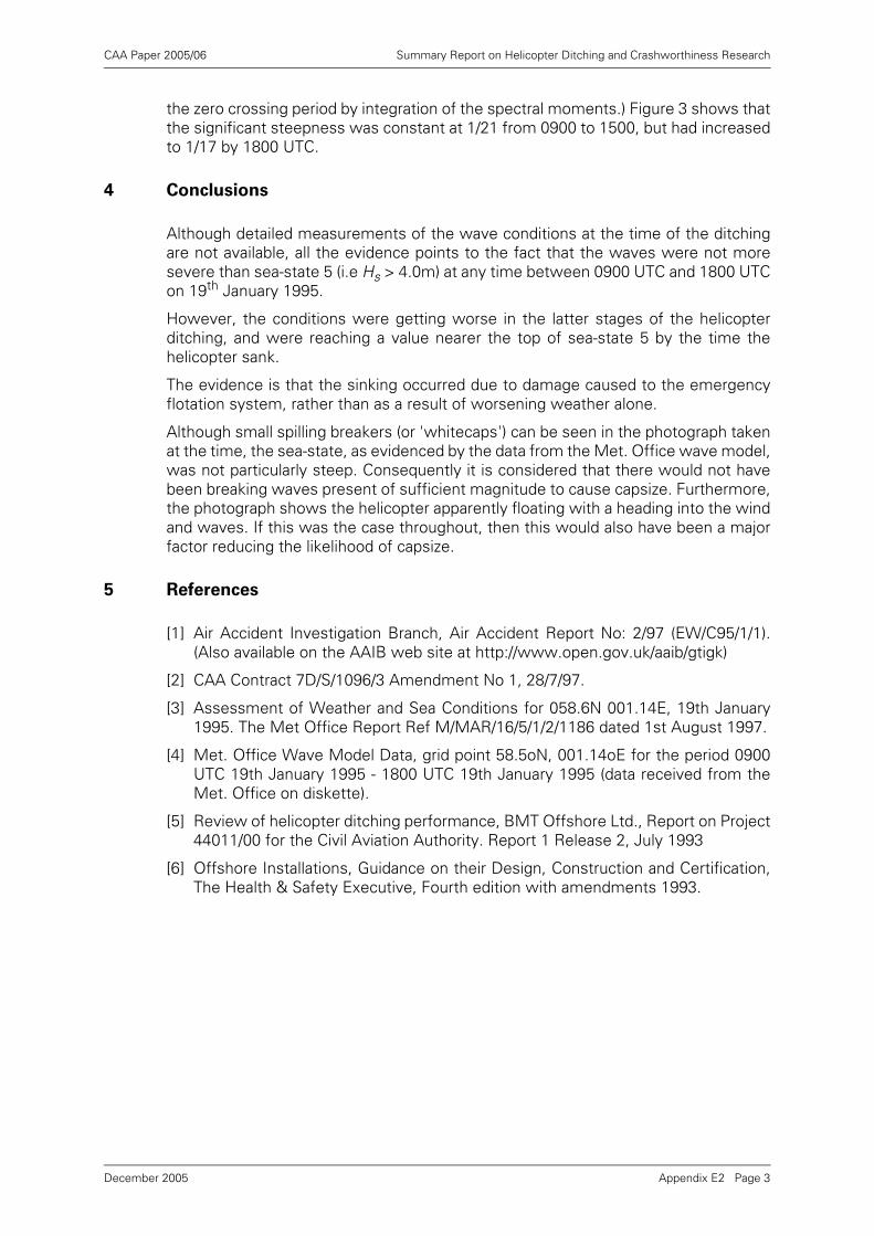
CAA Paper 2005/06 Summary Report on Helicopter Ditching and Crashworthiness Research
the zero crossing period by integration of the spectral moments.) Figure 3 shows thatthe significant steepness was constant at 1/21 from 0900 to 1500, but had increasedto 1/17 by 1800 UTC.
4 Conclusions
Although detailed measurements of the wave conditions at the time of the ditchingare not available, all the evidence points to the fact that the waves were not moresevere than sea-state 5 (i.e Hs > 4.0m) at any time between 0900 UTC and 1800 UTCon 19th January 1995.
However, the conditions were getting worse in the latter stages of the helicopterditching, and were reaching a value nearer the top of sea-state 5 by the time thehelicopter sank.
The evidence is that the sinking occurred due to damage caused to the emergencyflotation system, rather than as a result of worsening weather alone.
Although small spilling breakers (or 'whitecaps') can be seen in the photograph takenat the time, the sea-state, as evidenced by the data from the Met. Office wave model,was not particularly steep. Consequently it is considered that there would not havebeen breaking waves present of sufficient magnitude to cause capsize. Furthermore,the photograph shows the helicopter apparently floating with a heading into the windand waves. If this was the case throughout, then this would also have been a majorfactor reducing the likelihood of capsize.
5 References
[1] Air Accident Investigation Branch, Air Accident Report No: 2/97 (EW/C95/1/1).(Also available on the AAIB web site at http://www.open.gov.uk/aaib/gtigk)
[2] CAA Contract 7D/S/1096/3 Amendment No 1, 28/7/97.
[3] Assessment of Weather and Sea Conditions for 058.6N 001.14E, 19th January1995. The Met Office Report Ref M/MAR/16/5/1/2/1186 dated 1st August 1997.
[4] Met. Office Wave Model Data, grid point 58.5oN, 001.14oE for the period 0900UTC 19th January 1995 - 1800 UTC 19th January 1995 (data received from theMet. Office on diskette).
[5] Review of helicopter ditching performance, BMT Offshore Ltd., Report on Project44011/00 for the Civil Aviation Authority. Report 1 Release 2, July 1993
[6] Offshore Installations, Guidance on their Design, Construction and Certification,The Health & Safety Executive, Fourth edition with amendments 1993.
Appendix E2 Page 3December 2005
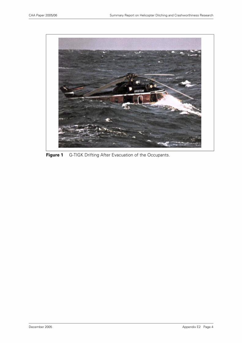
CAA Paper 2005/06 Summary Report on Helicopter Ditching and Crashworthiness Research
Figure 1 G-TIGK Drifting After Evacuation of the Occupants.
Appendix E2 Page 4December 2005
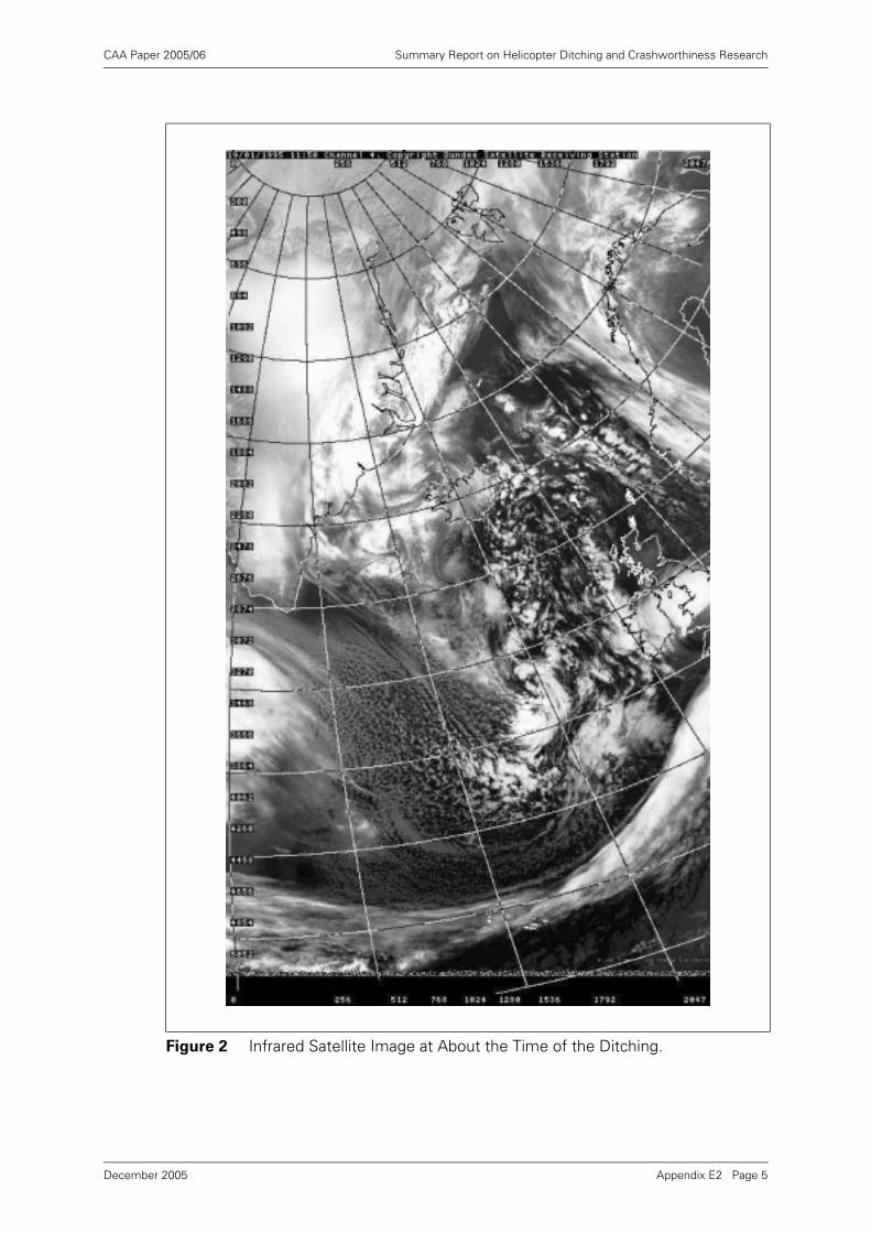
CAA Paper 2005/06 Summary Report on Helicopter Ditching and Crashworthiness Research
Figure 2 Infrared Satellite Image at About the Time of the Ditching.
Appendix E2 Page 5December 2005
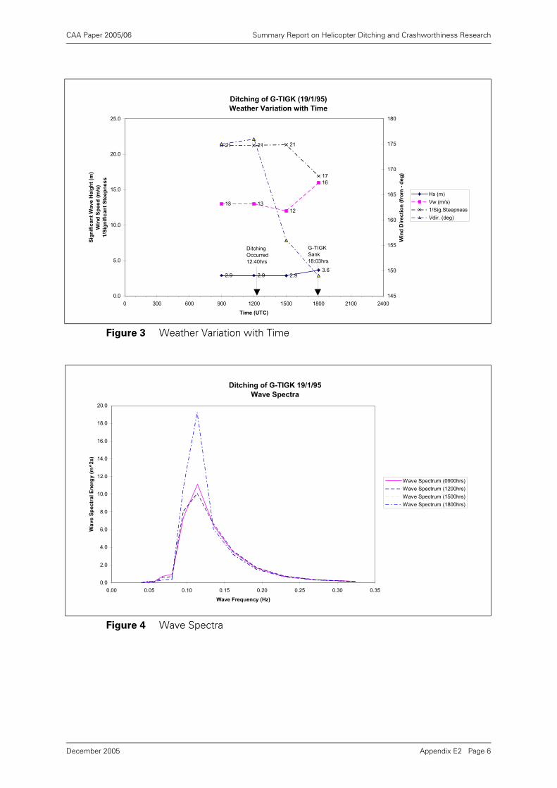
CAA Paper 2005/06 Summary Report on Helicopter Ditching and Crashworthiness Research
Figure 3 Weather Variation with Time
Figure 4 Wave Spectra
Ditching of G-TIGK (19/1/95)
Weather Variation with Time
13 13
12
16
21 21 21
17
2.9 2.9 2.93.6
0.0
5.0
10.0
15.0
20.0
25.0
0 300 600 900 1200 1500 1800 2100 2400
Time (UTC)
Sig
nif
ica
nt
Wa
ve
He
igh
t (m
)
Win
d S
peed
(m
/s)
1/S
ign
ific
an
t S
tee
pn
es
s
145
150
155
160
165
170
175
180
Win
d D
ire
cti
on
(fr
om
- d
eg
)
Hs (m)
Vw (m/s)
1/Sig.Steepness
Vdir. (deg)
Ditching
Occurred
12:40hrs
G-TIGK
Sank
18:03hrs
Ditching of G-TIGK 19/1/95
Wave Spectra
0.0
2.0
4.0
6.0
8.0
10.0
12.0
14.0
16.0
18.0
20.0
0.00 0.05 0.10 0.15 0.20 0.25 0.30 0.35
Wave Frequency (Hz)
Wa
ve
Sp
ec
tra
l E
ne
rgy
(m
^2
s)
Wave Spectrum (0900hrs)
Wave Spectrum (1200hrs)
Wave Spectrum (1500hrs)
Wave Spectrum (1800hrs)
Appendix E2 Page 6December 2005
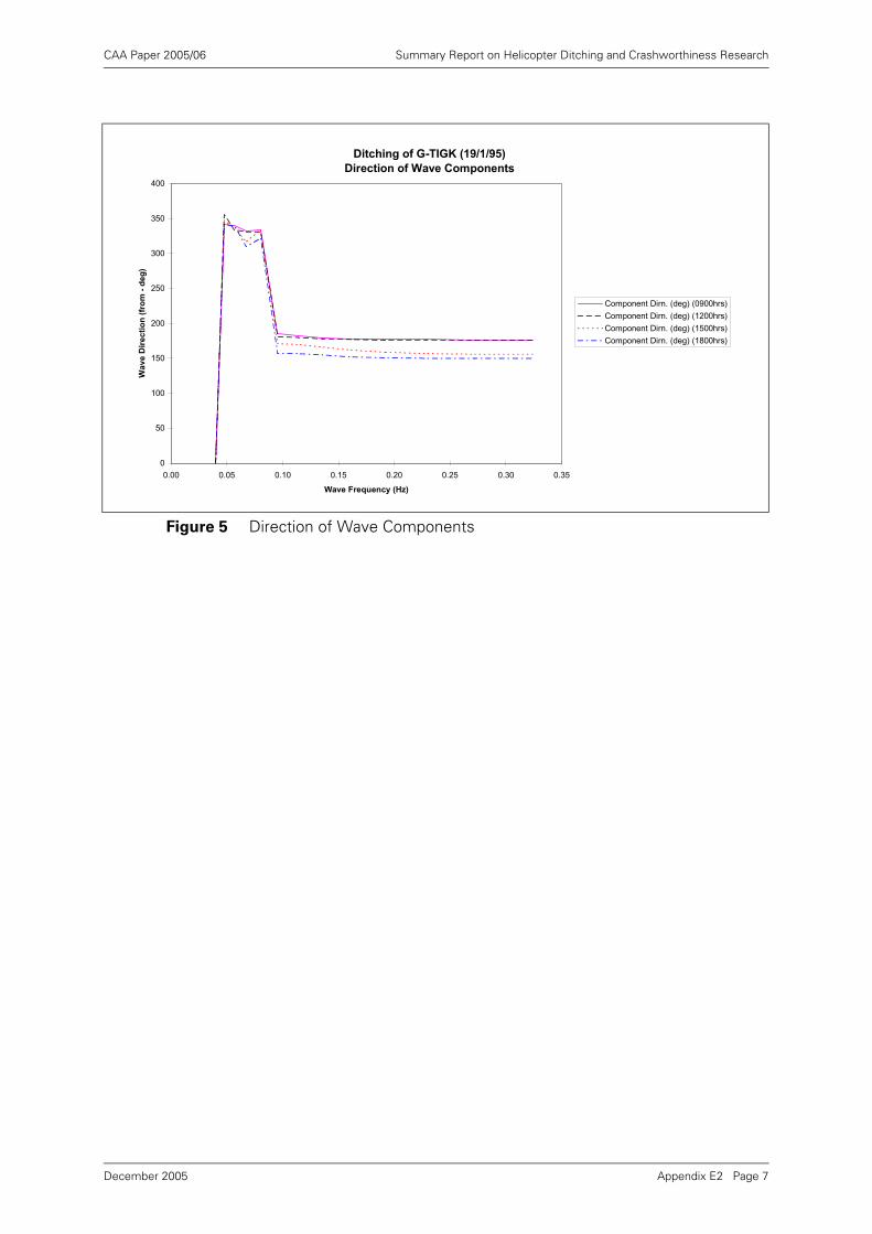
CAA Paper 2005/06 Summary Report on Helicopter Ditching and Crashworthiness Research
Figure 5 Direction of Wave Components
Ditching of G-TIGK (19/1/95)
Direction of Wave Components
0
50
100
150
200
250
300
350
400
0.00 0.05 0.10 0.15 0.20 0.25 0.30 0.35
Wave Frequency (Hz)
Wa
ve
Dir
ec
tio
n (
fro
m -
de
g)
Component Dirn. (deg) (0900hrs)
Component Dirn. (deg) (1200hrs)
Component Dirn. (deg) (1500hrs)
Component Dirn. (deg) (1800hrs)
Appendix E2 Page 7December 2005
CAA Paper 2005/06 Summary Report on Helicopter Ditching and Crashworthiness Research
Appendix F HOSS Paper on Helicopter Safety and
Occupant Survivability
Ref. HOSS/WP-99/8.5
OFFSHORE OPERATIONS - HELICOPTER SAFETY AND OCCUPANT
SURVIVABILITY FOLLOWING DITCHING OR WATER IMPACT
1 Aim
The aim of this paper is to review the airworthiness standards currently associatedwith both intentional ditching and unintentional water impact in the light of serviceexperience and ongoing research into occupant safety and survivability, and torecommend where improvements should be made.
Over-water helicopter operations are permitted in the knowledge that emergencysituations may arise which require an immediate and forced landing. Accordingly,ICAO Annex 6 Part 3 paragraphs 2.2.11 and 4.5.1, and national operating rules specifythose circumstances where approved flotation and safety equipment must be carried,and ICAO states that Sea State shall be an integral part of ditching information.
Currently, in both JAR and FAR rotorcraft airworthiness requirements, there are twostandards of flotation equipment which can be approved. The first, which is applicableto both JAR/FAR 27 and 29 is Ditching Equipment. The second, which is onlyapplicable to JAR/FAR 27 is referred to as Emergency Flotation Equipment. Theairworthiness requirements applicable to both are generally the same except thatEmergency Flotation Equipment is not required to meet any prescribed standards forthe water entry phase.
FAA Advisory Circulars AC 27-1 and 29-2 define Ditching as an emergency landing onthe water, deliberately executed, with the intent of abandoning the rotorcraft as soonas practical. For the purposes of this paper, it is assumed that Emergency FlotationEquipment is intended to achieve the same aim as Ditching Equipment.
Following a ditching onto the surface of the water however, there are conditionswhich will cause a helicopter floating upright to capsize before abandonment hasbeen completed. In these circumstances, evacuation will have to be carried out froman inverted and flooded cabin with the occupants probably suffering from severedisorientation and cold water shock. Service experience has brought about a numberof design features which can significantly enhance occupant survivability in thesecircumstances. A number of these features are currently not required by theairworthiness codes.
Accident data indicates that unintentional water impact is also to be expected and, inotherwise survivable crashes, the major cause of fatalities is drowning. There arecurrently no crashworthiness certification requirements specific to water impact.Recent research into accident data has concluded that improvements in thecrashworthiness of flotation equipment would significantly enhance post crashsurvivability.
Appendix F Page 1December 2005
CAA Paper 2005/06 Summary Report on Helicopter Ditching and Crashworthiness Research
2 Discussion
2.1 General
Both JAR and FAR rotorcraft airworthiness codes currently contain a number ofrequirements, some optional, appropriate to the potential need to carry out anemergency alighting on the water. FAR/JAR 27 and 29.801 Ditching requires that therotorcraft must under reasonably probable water conditions, be shown to be
able to remain upright on the surface of the water for sufficient time to allow
the occupants to leave the rotorcraft and enter the life-rafts. It is recognised inthe code however, that the rotorcraft may be capsized and that occupants may haveto escape from an inverted and flooded hull. A review of operational experience in theNorthern European offshore areas indicates that current JAR/FAR requirements donot adequately address all aspects of ditching and subsequent occupant safety andsurvivability. A summary of over-water accidents is provided at Annex A. Thefollowing requirement inadequacies have been identified.
2.2 Ditching Flotation Stability
2.2.1 Capsize Boundary
As previously stated FAR/JAR 27/29.801 Ditching requires under paragraph (d) thatflotation and stability must be demonstrated in reasonably probable sea conditions.Paragraph (b) requires that measures must be taken to minimise the probability
that in an emergency landing on water, the behaviour of the rotorcraft would
cause immediate injury to the occupants or would make it impossible for them
to escape. Experience suggests that the greatest risk to the occupants in a ditchingis drowning due to inability to evacuate the aircraft following a capsize andsubsequent flooding of the hull.
Taken on their own, the FAR/JAR would require the designer to select a reasonablysevere wave condition for the area in which he expects the helicopter to operate andto demonstrate that the probability of a capsize has been minimised. FAA and JAAhowever, have adopted an interpretation (AC29-2A paragraph 337(a)(3)) which statesthat Sea State 4 is considered to satisfy the reasonably probable requirement.
Although sea keeping qualities vary from one helicopter type to another, most typescurrently in use will capsize in sea states in the range 4 to 5 and above. A recent studyof wave climates along a representative selection of main helicopter routes in thenorthern North Sea and West of Shetland (regarded in JAR-OPS 3 as a Hostileenvironment), indicates that Sea State 4 will be exceeded on 26-36% of occasionsover the whole year (Ref. 1). During the winter period between December-February,this increases to between 51-65%. If the certification requirement was raised to SeaState 6, the risk of exceedance would fall to a maximum of approximately 3% overthe whole year and 3-7% in the winter months.
Research into the effects of fitting scoops to flotation equipment has demonstratedan improvement in the resistance to capsize of most helicopters (Ref. 2). Thisindicates that expectations of improvements in flotation stability of the order of onesea state are realistic. Installation of scoops does however increase loads on flotationequipment and the airframe. This will affect airframe weight and costs but these havebeen estimated to be quite modest, i.e. fitting scoops to a large helicopter wouldresult in an overall increase in cost of the helicopter of about 0.3%. This is consideredto be justifiable when compared with the significant reduction in the risk of capsize.
Whereas the proposal to require enhanced flotation stability is considered appropriatefor operations in hostile environments such as the North Sea, it may not beappropriate for a number of other operating environments, e.g. the Gulf of Mexico.
Appendix F Page 2December 2005
CAA Paper 2005/06 Summary Report on Helicopter Ditching and Crashworthiness Research
Having regard to current FAA and JAA operating rules and Industry requirements forstraightforward certification standards, the following is proposed:
a) For Non-Hostile environment; Emergency Flotation Equipment should be the
standard. The current interpretation of the JAR/FAR 27.801(d) requirement
to demonstrate flotation stability in reasonably probable sea conditions as
being Sea State 4, is considered to be appropriate for this class of flotation
equipment.
b) For hostile environments; the flotation stability requirement of JAR/FAR 27
and 29 should be amended to require a higher standard of Sea State 6 for
Ditching Equipment.
NOTE: As Sea State codes are ambiguous, capsize boundary targets should bespecified in terms of significant wave height, zero crossing period and wavespectrum.
2.2.2 Demonstration of Compliance
The traditional method of demonstrating compliance with 27/29.801(d) is todetermine a capsize boundary by model testing in regular wave conditions of a givenmaximum height/length ratio. This methodology has been discredited by navalarchitects who state that results of such tests are likely to depend more on theproperties of the wave basin at the test facility than of the helicopter model itself. Thisis because capsizes are caused by breaking waves and the breaking of a regular wavein a basin is largely a matter of wave quality. Consequently, the best helicopterperformance will appear to be obtained in the basin that can generate the steepestnon-breaking regular waves. Numerous wave basins are now available that cangenerate irregular waves which are significantly more representative of actual seaconditions. Investigation has shown that the cost of regular and irregular wave testingcan be comparable.
If irregular wave testing is to be adopted, the immediate questions are whatprobability of capsize and what period of exposure should be regarded as acceptable.Historically, an exposure period of 5 minutes to allow for rotor run-down, life-raftdeployment and egress of all occupants has been assumed and there appears to beno compelling reason to modify this figure.
As regards probability of capsize, one approach would be to set a safety target basedon the likelihood of its occurrence, derived from service experience, and theconsequences of the failure condition. This has the advantage of producing a rationalmethodology for determining a certification test plan. In the absence of any form ofmitigation, a helicopter ditching which results in a capsize before the occupants canmake good their escape could be expected to cause the death of a number of themthrough drowning; there is known to be an incompatibility between breath holdcapability in typical North Sea temperatures and escape times from a capsizedhelicopter despite the use of immersion suits (Ref. 7). Efforts should therefore bemade to determine the current ditching/capsize rate and define a safety targetappropriate to the consequences of a capsize. A comparison of the two woulddetermine the scope of certification effort required to meet the ditching requirementof 27 & 29.801, as previously stated.
In view of the above, it is proposed that:
a) The AC material be amended to specify irregular wave testing with an
appropriate exposure period and target probability of capsize.
b) A standard test protocol for demonstration of compliance using irregular
wave testing be developed and adopted.
Appendix F Page 3December 2005
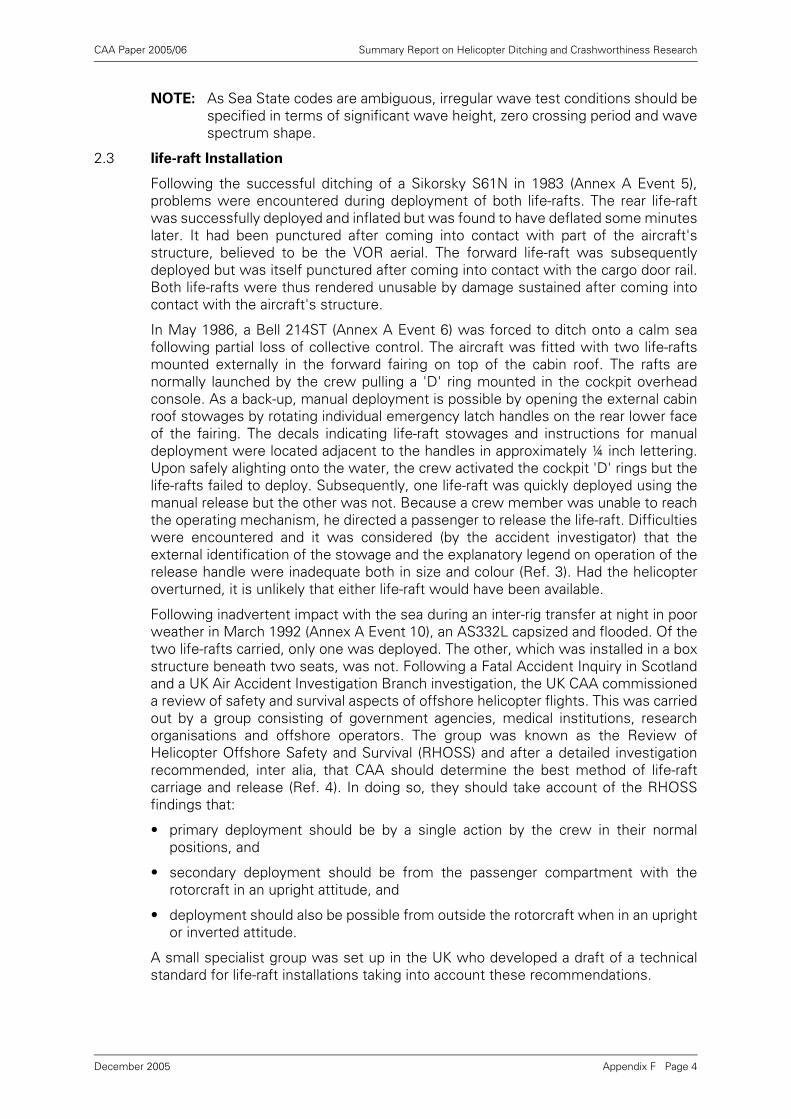
CAA Paper 2005/06 Summary Report on Helicopter Ditching and Crashworthiness Research
NOTE: As Sea State codes are ambiguous, irregular wave test conditions should bespecified in terms of significant wave height, zero crossing period and wavespectrum shape.
2.3 life-raft Installation
Following the successful ditching of a Sikorsky S61N in 1983 (Annex A Event 5),problems were encountered during deployment of both life-rafts. The rear life-raftwas successfully deployed and inflated but was found to have deflated some minuteslater. It had been punctured after coming into contact with part of the aircraft'sstructure, believed to be the VOR aerial. The forward life-raft was subsequentlydeployed but was itself punctured after coming into contact with the cargo door rail.Both life-rafts were thus rendered unusable by damage sustained after coming intocontact with the aircraft's structure.
In May 1986, a Bell 214ST (Annex A Event 6) was forced to ditch onto a calm seafollowing partial loss of collective control. The aircraft was fitted with two life-raftsmounted externally in the forward fairing on top of the cabin roof. The rafts arenormally launched by the crew pulling a 'D' ring mounted in the cockpit overheadconsole. As a back-up, manual deployment is possible by opening the external cabinroof stowages by rotating individual emergency latch handles on the rear lower faceof the fairing. The decals indicating life-raft stowages and instructions for manualdeployment were located adjacent to the handles in approximately ¼ inch lettering.Upon safely alighting onto the water, the crew activated the cockpit 'D' rings but thelife-rafts failed to deploy. Subsequently, one life-raft was quickly deployed using themanual release but the other was not. Because a crew member was unable to reachthe operating mechanism, he directed a passenger to release the life-raft. Difficultieswere encountered and it was considered (by the accident investigator) that theexternal identification of the stowage and the explanatory legend on operation of therelease handle were inadequate both in size and colour (Ref. 3). Had the helicopteroverturned, it is unlikely that either life-raft would have been available.
Following inadvertent impact with the sea during an inter-rig transfer at night in poorweather in March 1992 (Annex A Event 10), an AS332L capsized and flooded. Of thetwo life-rafts carried, only one was deployed. The other, which was installed in a boxstructure beneath two seats, was not. Following a Fatal Accident Inquiry in Scotlandand a UK Air Accident Investigation Branch investigation, the UK CAA commissioneda review of safety and survival aspects of offshore helicopter flights. This was carriedout by a group consisting of government agencies, medical institutions, researchorganisations and offshore operators. The group was known as the Review ofHelicopter Offshore Safety and Survival (RHOSS) and after a detailed investigationrecommended, inter alia, that CAA should determine the best method of life-raftcarriage and release (Ref. 4). In doing so, they should take account of the RHOSSfindings that:
• primary deployment should be by a single action by the crew in their normalpositions, and
• secondary deployment should be from the passenger compartment with therotorcraft in an upright attitude, and
• deployment should also be possible from outside the rotorcraft when in an uprightor inverted attitude.
A small specialist group was set up in the UK who developed a draft of a technicalstandard for life-raft installations taking into account these recommendations.
Appendix F Page 4December 2005
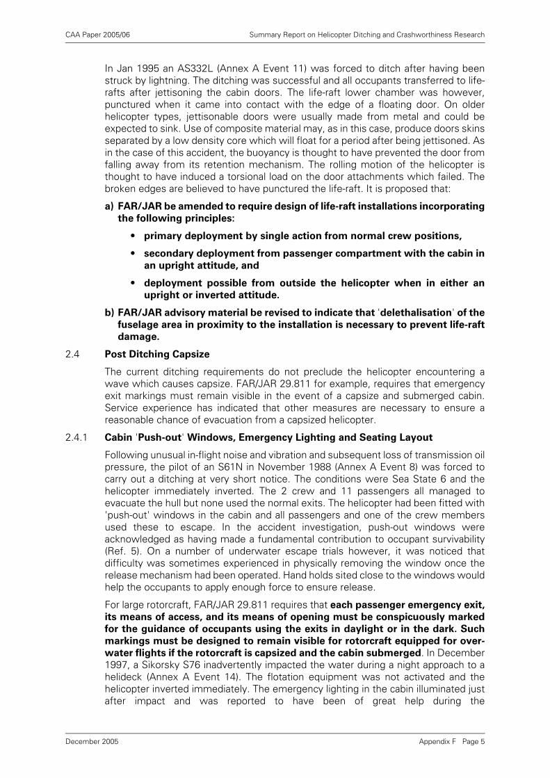
CAA Paper 2005/06 Summary Report on Helicopter Ditching and Crashworthiness Research
In Jan 1995 an AS332L (Annex A Event 11) was forced to ditch after having beenstruck by lightning. The ditching was successful and all occupants transferred to life-rafts after jettisoning the cabin doors. The life-raft lower chamber was however,punctured when it came into contact with the edge of a floating door. On olderhelicopter types, jettisonable doors were usually made from metal and could beexpected to sink. Use of composite material may, as in this case, produce doors skinsseparated by a low density core which will float for a period after being jettisoned. Asin the case of this accident, the buoyancy is thought to have prevented the door fromfalling away from its retention mechanism. The rolling motion of the helicopter isthought to have induced a torsional load on the door attachments which failed. Thebroken edges are believed to have punctured the life-raft. It is proposed that:
a) FAR/JAR be amended to require design of life-raft installations incorporating
the following principles:
• primary deployment by single action from normal crew positions,
• secondary deployment from passenger compartment with the cabin in
an upright attitude, and
• deployment possible from outside the helicopter when in either an
upright or inverted attitude.
b) FAR/JAR advisory material be revised to indicate that 'delethalisation' of the
fuselage area in proximity to the installation is necessary to prevent life-raft
damage.
2.4 Post Ditching Capsize
The current ditching requirements do not preclude the helicopter encountering awave which causes capsize. FAR/JAR 29.811 for example, requires that emergencyexit markings must remain visible in the event of a capsize and submerged cabin.Service experience has indicated that other measures are necessary to ensure areasonable chance of evacuation from a capsized helicopter.
2.4.1 Cabin 'Push-out' Windows, Emergency Lighting and Seating Layout
Following unusual in-flight noise and vibration and subsequent loss of transmission oilpressure, the pilot of an S61N in November 1988 (Annex A Event 8) was forced tocarry out a ditching at very short notice. The conditions were Sea State 6 and thehelicopter immediately inverted. The 2 crew and 11 passengers all managed toevacuate the hull but none used the normal exits. The helicopter had been fitted with'push-out' windows in the cabin and all passengers and one of the crew membersused these to escape. In the accident investigation, push-out windows wereacknowledged as having made a fundamental contribution to occupant survivability(Ref. 5). On a number of underwater escape trials however, it was noticed thatdifficulty was sometimes experienced in physically removing the window once therelease mechanism had been operated. Hand holds sited close to the windows wouldhelp the occupants to apply enough force to ensure release.
For large rotorcraft, FAR/JAR 29.811 requires that each passenger emergency exit,
its means of access, and its means of opening must be conspicuously marked
for the guidance of occupants using the exits in daylight or in the dark. Such
markings must be designed to remain visible for rotorcraft equipped for over-
water flights if the rotorcraft is capsized and the cabin submerged. In December1997, a Sikorsky S76 inadvertently impacted the water during a night approach to ahelideck (Annex A Event 14). The flotation equipment was not activated and thehelicopter inverted immediately. The emergency lighting in the cabin illuminated justafter impact and was reported to have been of great help during the
Appendix F Page 5December 2005
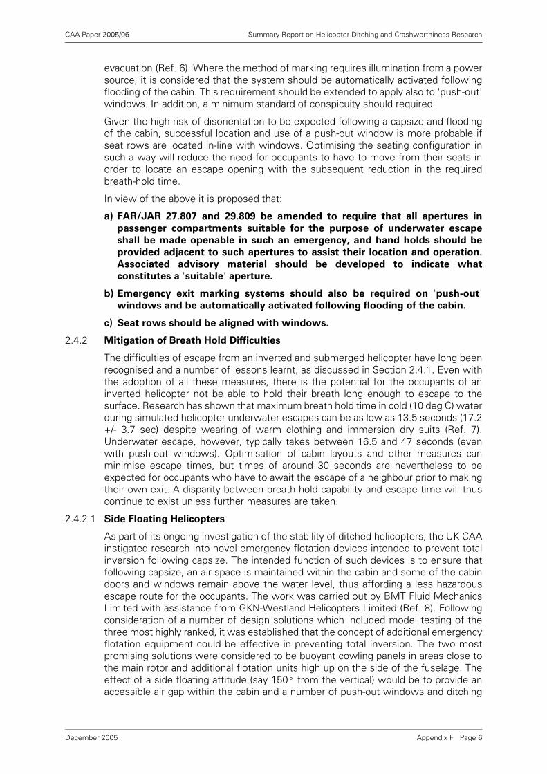
CAA Paper 2005/06 Summary Report on Helicopter Ditching and Crashworthiness Research
evacuation (Ref. 6). Where the method of marking requires illumination from a powersource, it is considered that the system should be automatically activated followingflooding of the cabin. This requirement should be extended to apply also to 'push-out'windows. In addition, a minimum standard of conspicuity should required.
Given the high risk of disorientation to be expected following a capsize and floodingof the cabin, successful location and use of a push-out window is more probable ifseat rows are located in-line with windows. Optimising the seating configuration insuch a way will reduce the need for occupants to have to move from their seats inorder to locate an escape opening with the subsequent reduction in the requiredbreath-hold time.
In view of the above it is proposed that:
a) FAR/JAR 27.807 and 29.809 be amended to require that all apertures in
passenger compartments suitable for the purpose of underwater escape
shall be made openable in such an emergency, and hand holds should be
provided adjacent to such apertures to assist their location and operation.
Associated advisory material should be developed to indicate what
constitutes a 'suitable' aperture.
b) Emergency exit marking systems should also be required on 'push-out'windows and be automatically activated following flooding of the cabin.
c) Seat rows should be aligned with windows.
2.4.2 Mitigation of Breath Hold Difficulties
The difficulties of escape from an inverted and submerged helicopter have long beenrecognised and a number of lessons learnt, as discussed in Section 2.4.1. Even withthe adoption of all these measures, there is the potential for the occupants of aninverted helicopter not be able to hold their breath long enough to escape to thesurface. Research has shown that maximum breath hold time in cold (10 deg C) waterduring simulated helicopter underwater escapes can be as low as 13.5 seconds (17.2+/- 3.7 sec) despite wearing of warm clothing and immersion dry suits (Ref. 7).Underwater escape, however, typically takes between 16.5 and 47 seconds (evenwith push-out windows). Optimisation of cabin layouts and other measures canminimise escape times, but times of around 30 seconds are nevertheless to beexpected for occupants who have to await the escape of a neighbour prior to makingtheir own exit. A disparity between breath hold capability and escape time will thuscontinue to exist unless further measures are taken.
2.4.2.1 Side Floating Helicopters
As part of its ongoing investigation of the stability of ditched helicopters, the UK CAAinstigated research into novel emergency flotation devices intended to prevent totalinversion following capsize. The intended function of such devices is to ensure thatfollowing capsize, an air space is maintained within the cabin and some of the cabindoors and windows remain above the water level, thus affording a less hazardousescape route for the occupants. The work was carried out by BMT Fluid MechanicsLimited with assistance from GKN-Westland Helicopters Limited (Ref. 8). Followingconsideration of a number of design solutions which included model testing of thethree most highly ranked, it was established that the concept of additional emergencyflotation equipment could be effective in preventing total inversion. The two mostpromising solutions were considered to be buoyant cowling panels in areas close tothe main rotor and additional flotation units high up on the side of the fuselage. Theeffect of a side floating attitude (say 150º from the vertical) would be to provide anaccessible air gap within the cabin and a number of push-out windows and ditching
Appendix F Page 6December 2005
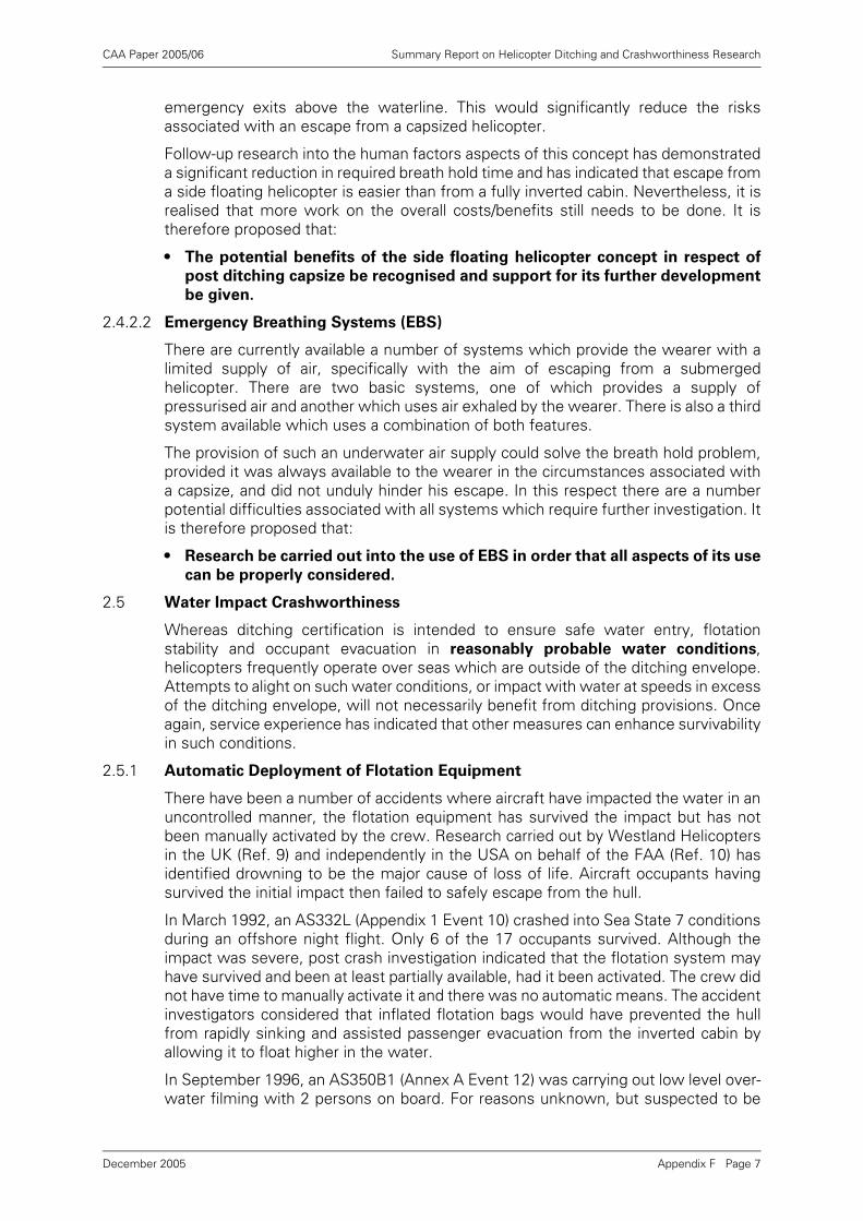
CAA Paper 2005/06 Summary Report on Helicopter Ditching and Crashworthiness Research
emergency exits above the waterline. This would significantly reduce the risksassociated with an escape from a capsized helicopter.
Follow-up research into the human factors aspects of this concept has demonstrateda significant reduction in required breath hold time and has indicated that escape froma side floating helicopter is easier than from a fully inverted cabin. Nevertheless, it isrealised that more work on the overall costs/benefits still needs to be done. It istherefore proposed that:
• The potential benefits of the side floating helicopter concept in respect of
post ditching capsize be recognised and support for its further development
be given.
2.4.2.2 Emergency Breathing Systems (EBS)
There are currently available a number of systems which provide the wearer with alimited supply of air, specifically with the aim of escaping from a submergedhelicopter. There are two basic systems, one of which provides a supply ofpressurised air and another which uses air exhaled by the wearer. There is also a thirdsystem available which uses a combination of both features.
The provision of such an underwater air supply could solve the breath hold problem,provided it was always available to the wearer in the circumstances associated witha capsize, and did not unduly hinder his escape. In this respect there are a numberpotential difficulties associated with all systems which require further investigation. Itis therefore proposed that:
• Research be carried out into the use of EBS in order that all aspects of its use
can be properly considered.
2.5 Water Impact Crashworthiness
Whereas ditching certification is intended to ensure safe water entry, flotationstability and occupant evacuation in reasonably probable water conditions,helicopters frequently operate over seas which are outside of the ditching envelope.Attempts to alight on such water conditions, or impact with water at speeds in excessof the ditching envelope, will not necessarily benefit from ditching provisions. Onceagain, service experience has indicated that other measures can enhance survivabilityin such conditions.
2.5.1 Automatic Deployment of Flotation Equipment
There have been a number of accidents where aircraft have impacted the water in anuncontrolled manner, the flotation equipment has survived the impact but has notbeen manually activated by the crew. Research carried out by Westland Helicoptersin the UK (Ref. 9) and independently in the USA on behalf of the FAA (Ref. 10) hasidentified drowning to be the major cause of loss of life. Aircraft occupants havingsurvived the initial impact then failed to safely escape from the hull.
In March 1992, an AS332L (Appendix 1 Event 10) crashed into Sea State 7 conditionsduring an offshore night flight. Only 6 of the 17 occupants survived. Although theimpact was severe, post crash investigation indicated that the flotation system mayhave survived and been at least partially available, had it been activated. The crew didnot have time to manually activate it and there was no automatic means. The accidentinvestigators considered that inflated flotation bags would have prevented the hullfrom rapidly sinking and assisted passenger evacuation from the inverted cabin byallowing it to float higher in the water.
In September 1996, an AS350B1 (Annex A Event 12) was carrying out low level over-water filming with 2 persons on board. For reasons unknown, but suspected to be
Appendix F Page 7December 2005
CAA Paper 2005/06 Summary Report on Helicopter Ditching and Crashworthiness Research
inadvertent closure of the fuel control lever, rotor rpm dropped and the aircraftdescended into the sea. Although the pilot attempted to, he did not have enough timeto manually activate the emergency flotation equipment. The helicopter impacted thesea, inverted with the subsequent loss of the passenger.
Provision of a means to automatically inflate both ditching and emergency floatationequipment could have prevented loss of life in the above accidents. It is thereforeproposed that:
• FAR/JAR 27 and 29.1415 be amended to require the provision of means to
automatically inflate both ditching and emergency flotation equipment
following water entry.
NOTE: For helicopters where is not possible for the emergency flotation system toremain armed throughout the flight, automatic disarming/rearming should berequired.
2.5.2 Flotation System Crashworthiness
As previously mentioned, the FAA and Westland Helicopters Limited accident reviewstudies both came to the conclusion that a significant cause of death in helicopterwater impacts was through drowning. They went on to further conclude that, had thehelicopter's emergency flotation system been more crashworthy, the risk ofdrowning could be significantly reduced. Follow-on studies were carried out by W SAtkins and BMT Fluid Mechanics Limited on behalf of the UK CAA. Their aim wasinitially, to determine if it would be possible to define enhanced structuralrequirements for emergency flotation systems based on loading cases experiencedduring survivable water impacts. Whilst this work found that it was not practical todefine such requirements, it did identify the benefits of a number of measures.
In the event of a survivable water impact, the risk of drowning will be greatest if thehelicopter rapidly sinks. To some degree, automatic deployment of the emergencyflotation system will reduce this risk but will not address the structural aspects of thesystem's survivability. The results of the BMT and WS Atkins research indicate thatprovision of redundant flotation at bag level rather than at compartment (within a bag)level, and relocation of flotation equipment away from primary impact sites couldprovide significant improvements in crashworthiness. It is therefore concluded thatenhancing crashworthiness could be combined with the possible future requirementfor means to prevent total inversion following post-ditching capsize (see paragraph2.4.2.1). Locating additional flotation on the upper part of the airframe would increaseflotation redundancy and minimise the effects of crash damage on the overallperformance of the flotation system.
Other measures were identified which, although not mentioned in the requirementsor advisory material, are considered to be standard practice within the industry. Thesemeasures included:
• Use of flexible hoses on flow distribution lines.
• Routing of hoses/wiring to avoid areas likely to be severely deformed in an impact.
• System deployment after impact with water.
• The flow distribution system should be designed to ensure equal float deployment(timing as well as volume) even with system/bag damage.
• Bags should be divided into multiple cells to limit the effects of minor bag ruptures.
Appendix F Page 8December 2005
CAA Paper 2005/06 Summary Report on Helicopter Ditching and Crashworthiness Research
In view of the above, it is recommended that:
a) The potential benefits of the side floating helicopter concept in respect of
flotation system crashworthiness be recognised and support for its further
development be given.
b) Appropriate requirements/advisory material be generated and adopted to
reflect current practice in terms of emergency flotation system
crashworthiness.
3 Conclusions
A review of current ditching and other certification requirements associated with thepossibility of a forced landing on or impact with water, clearly indicates that occupantsurvivability considerations do not take account of service experience. In addition, theaccepted method of compliance for determining flotation stability is no longerconsidered to be acceptable.
Through service experience and associated research, a number of design featureshave been identified which would enhance occupant survivability following a waterlanding/impact. In some instances these features are already accepted asrepresenting a minimum standard for over-water operations in hostile areas. It isconsidered that certification requirements should urgently be reviewed and amendedto reflect an improved airworthiness standard.
4 Recommendations
It is recommended that JAA, FAA and Industry urgently carry out a review of JAR/FAR27 and 29 airworthiness requirements with a view to update those associated withditching and water impact crashworthiness. This effort should address both short andlonger term aims as indicated below:
4.1 Recommended Changes to Requirements
Research and service experience indicates that the following proposals are justified;
a) Revision of FAR/JAR 27 and 29.801 advisory material to indicate that reasonably
probable water conditions for Ditching Equipment certification should beequivalent to Sea State 6, and Sea State 4 for Emergency Flotation Equipment(capsize boundary targets to be specified in terms of significant wave height, zerocrossing period and wave spectrum). See paragraph 2.2.1.
b) Revision of FAR/JAR 27 and 29.801 advisory material to indicate that flotationstability substantiation should be based on representative (model) testing inirregular waves, and that an associated standard test protocol should be developedand adopted. See paragraph 2.2.2.
c) Revision of FAR/JAR 29.1411 and associated advisory material to require designof life-raft installation and methods of deployment to take account of the ditchingenvelope w.r.t. sea conditions, and to be operable and accessible when thehelicopter is both upright and capsized. Furthermore, projections on the exterior ofthe rotorcraft which may damage a deployed life-raft must be either moved ordelethalised. See paragraph 2.3.
d) Revision of FAR/JAR 29.809 to add a new requirement that all apertures inpassenger compartments suitable for the purpose of underwater escape shall beopenable in an emergency, and that hand holds should be provided adjacent to
Appendix F Page 9December 2005
CAA Paper 2005/06 Summary Report on Helicopter Ditching and Crashworthiness Research
such apertures to assist their location and operation. Additionally, guidance shouldindicate that passenger seating should be arranged so that each seat row is alignedwith a 'push-out' window, and that emergency exit marking systems should beautomatically activated following flooding of the cabin. See paragraph 2.4.1.
e) Revision of FAR/JAR 29.1415 to require that any flotation system installed to meetditching requirements, should be designed so as to automatically inflate uponwater entry (to include automatic arming where appropriate). See paragraph 2.5.1.
f) Addition of new material to FAR/JAR to reflect current best practice in terms ofemergency flotation system crashworthiness. See paragraph 2.5.2.
4.2 Recommended Future Work
a) As a matter of urgency, establish the regulatory need and expected benefits/disbenefits of emergency breathing systems carried to enhance the prospects ofsuccessful egress from an inverted and flooded cabin.
b) Establish the costs and expected benefits/disbenefits of redundant flotation unitsconfigured so as to produce a 'side floating' helicopter following capsize.
5 References
[1] BMT Fluid Mechanics Project No. 44140/00 - Wave Height Probabilities onHelicopter Routes (17 July, 1997).
[2] CAA Paper 95010 - Helicopter Float Scoops (December 1995).
[3] UK AAIB Accident Report 9/87.
[4] UK CAA CAP 641 - Review of Helicopter Offshore Safety and Survivability.
[5] UK AAIB Accident Report 1/90.
[6] Dutch Transport Safety Board Accident Report on Sikorsky S76-B (PH-KHB).
[7] Tipton, M.J. The Relationship Between Maximum Breath Hold Time in Air andthe Ventilatory Responses to Immersion in Cold Water. Eur. J. Appl. Physiol.(1992) 64: 426-429.
[8] CAA Paper 97010 - Devices to Prevent Helicopter Total Inversion Following aDitching.
[9] CAA Paper 96005 - Helicopter Crashworthiness.
[10] FAA Reports DOT/FAA/CT-92/13 & 14 - Rotorcraft Ditchings and Water RelatedImpacts that Occurred from 1982-1989.
Appendix F Page 10December 2005
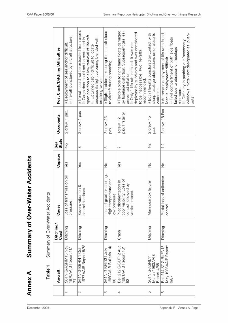
CAA Paper 2005/06 Summary Report on Helicopter Ditching and Crashworthiness Research
An
ne
x A
Su
mm
ary
of
Ov
er-
Wa
ter
Accid
en
ts
Ta
ble
1S
umm
ary
of O
ver-
Wat
er A
ccid
ents
Air
cra
ftD
itch
ing
/C
rash
Ca
use
Ca
psiz
eS
ea
S
tate
Occu
pan
tsP
ost
Cra
sh
/Dit
ch
ing
Dif
ficu
ltie
s
1S
61N
G-A
SN
M15
Nov
19
70A
AIB
Rep
ort
11/
71
Ditc
hing
Loss
of
tran
smis
sion
oil
pres
sure
.Ye
s4-
52
crew
, 1 p
ax.
i) D
eplo
ymen
t of
sea
anc
hor
diff
icul
t.ii)
life
-raf
t pu
nctu
red
by a
ircra
ft s
truc
ture
.
2S
61N
G-B
BH
N 1
Oct
19
77.A
AIB
Rep
ort
8/78
Ditc
hing
Sev
ere
vibr
atio
n &
co
ntro
l fee
dbac
k.Ye
s8
2 cr
ew, 1
pax
i) lif
e-ra
ft c
ould
not
be
extr
acte
d fr
om c
abin
.ii)
Car
go d
oor
coul
d no
t be
res
trai
ned
in
open
pos
ition
to
allo
w r
etrie
val o
f lif
e-ra
ft.
iii) U
ptur
ned
cabi
n di
ffic
ult
to lo
cate
be
caus
e its
ligh
t co
lour
ing
blen
ded
with
br
eaki
ng w
aves
3S
61N
G-B
EID
31 J
uly
1980
AA
IB B
ulle
tin 1
4/80
Ditc
hing
Loss
of
gear
box
cool
ing.
H
igh
tem
pera
ture
and
lo
w p
ress
ure.
No
32
crew
, 13
pax.
i) S
light
pro
blem
s ke
epin
g th
e lif
e-ra
ft c
lose
to
airc
raft
dur
ing
boar
ding
.
4B
ell 2
12 G
-BIJ
F12
Aug
19
81A
AIB
Rep
ort
10/
82
Cra
shP
ilot
diso
rient
atio
n in
po
or v
isib
ility
. Los
s of
co
ntro
l fol
low
ed b
y ve
rtic
al im
pact
.
Yes
?1c
rew
, 12
pax.
1 fa
talit
y.i)
Flex
ible
pip
e to
righ
t han
d flo
ats
dam
aged
by
fuse
lage
dis
tort
ion.
Sub
sequ
ent g
as le
ak
prev
ente
d in
flatio
n.ii)
Onl
y 1
life-
raft
inst
alle
d. It
was
not
de
ploy
ed b
y su
rviv
ors
and
was
con
side
red
to b
e in
acce
ssib
le. T
wo
life-
raft
s re
com
men
ded.
5S
61N
G-A
SN
L11
Mar
ch 1
983A
AIB
R
epor
t 4/
85
Ditc
hing
Mai
n ge
arbo
x fa
ilure
No
1-2
2 cr
ew, 1
5 pa
x.i)
Bot
h lif
e-ra
fts
punc
ture
d by
con
tact
with
sh
arp
fuse
lage
obs
truc
tions
on
or c
lose
to
wat
erlin
e.6
Bel
l 214
ST
G-B
KFN
15
May
198
6AA
IB R
epor
t 9/
87
Ditc
hing
Part
ial l
oss
of c
olle
ctiv
e co
ntro
lN
o1-
22
crew
, 18
Pax
i) A
utom
atic
dep
loym
ent
of li
fe-r
afts
faile
d.
Man
ual d
eplo
ymen
t di
ffic
ult.
ii) F
wd
com
part
men
t of
bot
h si
de f
loat
s fa
iled
due
to a
bras
ion
on f
usel
age
mem
bers
.iii
) Diff
icul
ty in
pus
hing
out
'sec
onda
ry'
win
dow
s. N
ote
- not
des
igna
ted
as 'p
ush-
outs
'
Appendix F Annex A Page 1December 2005
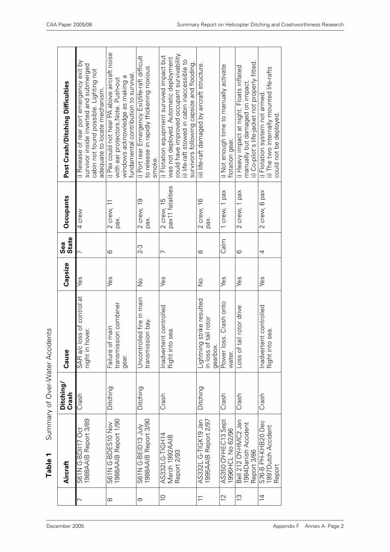
CAA Paper 2005/06 Summary Report on Helicopter Ditching and Crashworthiness Research
7S
61N
G-B
DII1
7 O
ct
1988
AA
IB R
epor
t 3/
89C
rash
SAR
a/c
loss
of c
ontr
ol a
t ni
ght
in h
over
.Ye
s?
4 cr
ewi)
Rel
ease
of
rear
por
t em
erge
ncy
exit
by
surv
ivor
insi
de in
vert
ed a
nd s
ubm
erge
d ca
bin
not
foun
d po
ssib
le. L
ight
ing
not
adeq
uate
to
loca
te m
echa
nism
.8
S61
N G
-BD
ES
10 N
ov
1988
AA
IB R
epor
t 1/
90D
itchi
ngFa
ilure
of
mai
n tr
ansm
issi
on c
ombi
ner
gear
.
Yes
62
crew
, 11
pax.
i) Pa
x co
uld
not h
ear P
A a
bove
airc
raft
noi
se
with
ear
pro
tect
ors.
Not
e. P
ush-
out
win
dow
s ac
know
ledg
e as
mak
ing
a fu
ndam
enta
l con
trib
utio
n to
sur
viva
l.9
S61
N G
-BE
ID13
Jul
y 19
88A
AIB
Rep
ort
3/90
Ditc
hing
Unc
ontr
olle
d fir
e in
mai
n tr
ansm
issi
on b
ay.
No
2-3
2 cr
ew, 1
9 pa
x.i)
Port
rea
r E
mer
genc
y E
xit/
life-
raft
diff
icul
t to
rel
ease
in r
apid
ly t
hick
enin
g no
xiou
s sm
oke.
10A
S33
2LG
-TIG
H14
M
arch
199
2AA
IB
Rep
ort
2/93
Cra
shIn
adve
rten
t co
ntro
lled
fligh
t in
to s
ea.
Yes
72
crew
, 15
pax1
1 fa
talit
ies
i) Fl
otat
ion
equi
pmen
t su
rviv
ed im
pact
but
w
as n
ot d
eplo
yed.
Aut
omat
ic d
eplo
ymen
t co
uld
have
impr
oved
occ
upan
t su
rviv
abili
ty.
ii) li
fe-r
aft
stow
ed in
cab
in in
acce
ssib
le t
o su
rviv
ors
follo
win
g ca
psiz
e an
d flo
odin
g.
11A
S33
2L G
-TIG
K19
Jan
19
95A
AIB
Rep
ort
2/97
Ditc
hing
Ligh
tnin
g st
rike
resu
lted
in lo
ss o
f ta
il ro
tor
gear
box.
No
62
crew
, 16
pax.
iii) l
ife-r
aft
dam
aged
by
airc
raft
str
uctu
re.
12A
S35
0 O
Y-H
EC
13 S
ept
1996
HC
L N
o 62
/96
Cra
shPo
wer
loss
. Cra
sh o
nto
wat
er.
Yes
Cal
m1
crew
, 1 p
axi)
Not
eno
ugh
time
to m
anua
lly a
ctiv
ate
flota
tion
gear
.13
Bel
l 212
OY-
HM
C2
Jan
1984
Dan
ish
Acc
iden
t R
epor
t 3/
86
Cra
shLo
ss o
f ta
il ro
tor
driv
eYe
s6
2 cr
ew, 1
pax
i) H
eavy
impa
ct a
t ni
ght.
Flo
ats
infla
ted
man
ually
but
dam
aged
on
impa
ct.
ii) C
o-pi
lot'
s lif
e-ja
cket
not
pro
perly
fitt
ed.
14S
76-B
PH
-KH
B20
Dec
19
97D
utch
Acc
iden
t R
epor
t
Cra
shIn
adve
rten
t co
ntro
lled
fligh
t in
to s
ea.
Yes
42
crew
, 6 p
axi)
Flot
atio
n sy
stem
not
arm
ed.
ii) T
he t
wo
inte
rnal
ly m
ount
ed li
fe-r
afts
co
uld
not
be d
eplo
yed.
Ta
ble
1S
umm
ary
of O
ver-
Wat
er A
ccid
ents
Air
cra
ftD
itch
ing
/C
rash
Ca
use
Ca
psiz
eS
ea
S
tate
Occu
pan
tsP
ost
Cra
sh
/Dit
ch
ing
Dif
ficu
ltie
s
Appendix F Annex A Page 2December 2005
CAA Paper 2005/06 Summary Report on Helicopter Ditching and Crashworthiness Research
Appendix G Water Impact, Ditching Design and
Crashworthiness Working Group
Recommendations
Water Impact/Ditching – Working Group
The Water Impact, Ditching Design, and Crashworthiness Working Group (WIDDCWG) wastasked by the Joint Harmonization Working Group (JHWG) to review the current regulatoryrequirements and advisory guidance pertaining to rotorcraft water impact and ditching, andreview existing research data associated with rotorcraft survivable water impact and ditchingscenarios. Based upon this review, the WIDDCWG was to survey effective interventionstrategies and present recommendations to the JHWG for changes or additions to the currentregulatory requirements and/or advisory guidance.
The WIDDCWG was comprised of representatives for the Federal Aviation Administration(FAA), Joint Aviation Authorities (JAA), Civil Aviation Authority (CAA), US and EuropeanIndustry. Over a period of approximately fifteen months, the WIDDCWG met on threeseparate occasions. The kick-off (first) meeting was held October 27 through 28, 1998 at theFAA Rotorcraft Directorate in Fort Worth, Texas. At this meeting, numerous researchdocuments were distributed to each of the team members for self-study and review. Basedon this self-study and review, each team member was tasked with developingrecommendations for intervention strategies and determining areas of concern pertaining tothe current regulatory requirements and/or advisory guidance.
The second meeting was held June 7 through 8, 1999 at Eurocopter in Marignane, France.During this meeting, briefings were presented on two research programs being conducted forthe CAA. The FAA discussed the current research activities that are being conducted by theU.S. Army, the U.S. Navy, and the FAA.
The third meeting was held January 18-20, 2000 in Las Vegas, Nevada, prior to the HAI Heli-Expo 2000. During this meeting, the final recommendations for changes/additions toregulatory and/or advisory guidance were discussed with a consensus vote on therecommendations for changes to address water impact/ditching for rotorcraft.
The following recommendations represent the cumulative efforts of the WIDDCWG and arepresented for the consideration and action of the JHWG. They are grouped under threeheadings: Water Impact, Ditching, and Post Ditching Egress/Survivability.
1 Water Impact.
1.1 Water Impact Crashworthiness.
Recommendation:
Structural ditching requirements should not be expanded to consider
crashworthiness due to:
a) high variability of the impact loads, and
b) impact loads in survivable accidents can be too high to design for in a
practical manner.
Appendix G Page 1December 2005
CAA Paper 2005/06 Summary Report on Helicopter Ditching and Crashworthiness Research
Structural ditching requirements are currently defined in terms of the horizontal andvertical velocities of the rotorcraft at the time of impact with the water. Researchindicates that, although impact velocity greatly affects impact loads, other impactparameters also have a significant effect. In particular, the attitude of the rotorcraftfuselage skin relative to the surface of the water at impact has a large effect on localimpact loads; it is not considered practical to define an impact attitude envelope asthis depends on the condition of the water surface at the point of impact as well asthe attitude of the itself, and is therefore highly variable.
Research into the range and variability of impact loads indicates that extremely highlocal impact loads can be generated in moderate (survivable) impacts. In the examplestudied, doubling the design strength was found to provide only a 15% improvementin crash resistance.
1.2 Automatic Activation of Flotation System.
Recommendation:
The activation flotation system should be automatically activated (either
primary or secondary means) upon sensing water immersion.
Analysis of accident data indicates that, in a significant number of impacts, theemergency flotation system did not deploy because it was not activated. Currentsystems typically require pilot activation of a manual switch for deployment. It isconsidered unreasonable to rely on manual activation in the event of an impact dueto the high risk of excessive pilot workload and/or pilot incapacitation.
1.3 Flotation System Arming/Disarming.
Recommendation:
During any flight over water, the possibility of the automatic float activation
feature being disabled e.g. deactivation of the system should be minimized.
Analysis of accident data indicates that, in a significant number of impacts, theemergency flotation system did not deploy because it was not armed. Many currentsystems require the pilot to manually arm the system prior to take-off, and thendisarm at a particular airspeed. In the event of an impact, the pilot is often unable tore-arm the system due to excessive workload and/or incapacitation. An automaticdisarming function, e.g. based on an airspeed switch, would eliminate this problem.Automatic activation by means of immersion sensing (Recommendation 2) isineffective if the system is not armed. The inclusion of an altitude sensing elementshould also be considered to cater for high speed, shallow descent impacts.
For rotorcraft for which inadvertent deployment could be hazardous, it is consideredundesirable for the emergency flotation to be armed unnecessarily, i.e., when notoperating over water.
1.4 Containment of Float Compartment Damage.
Recommendation:
Float bag design should provide a means to minimize the likelihood of tear
propagation between compartments.
1.5 External Handholds/Life Lines
Recommendation:
Handhold/life lines should be installed where practical and feasible to allow
person to hold on to an upright or inverted rotorcraft. (for AC)
Appendix G Page 2December 2005
CAA Paper 2005/06 Summary Report on Helicopter Ditching and Crashworthiness Research
Accidents have occurred where survivors have escaped from the cabin but have notbeen able to board a life-raft and have had difficulties finding anything to grasp in orderto stay afloat.
2 Ditching
2.1 Ditching Flotation Stability
Recommendation:
The current interpretation of 27/29.801 (d) 'reasonably probable water
conditions' should be amended to address a broader consideration of regional
climatic sea conditions.
Current AC material for 27/20.801 Ditching, interprets “reasonable probable waterconditions” as Sea State 4. A review conducted by the UK CAA indicated that in somerotorcraft operating areas, there is significant exposure over the year to sea conditionswhich exceed those modelled during ditching certification. A study of North Sea waveclimate data along six representative rotorcraft routes has established that theprobability of exceeding Sea State 4, the current design target in the AC material, is28% averaged over the whole year. This rises to 51% during the winter months. Inview of the ditching rate and the likely consequences of a capsize, a higher designtarget for the certification of ditching flotation systems is considered necessary.Given this and the practicality of achieving better roll stability by the incorporation offeatures such as float scoops (see paragraph 2.3), higher standards for ditchingcertification should be considered. It was noted however, that the predominant useof single engine rotorcraft in non hostile sea area could allow retention of existing seastate requirements for rotorcraft fitted with Emergency Flotation Equipment (seeparagraph 2.2)
2.2 Emergency Flotation Equipment Stability Requirements
Recommendation:
Maintain present Sea State 4 for emergency flotation systems and a higher Sea
State for ditching flotation systems.
It is recommended that the reference to Sea State 4 in the AC material be replacedby two sets of wave conditions corresponding to emergency flotation systems andditching flotation systems. The rotorcraft equipped with emergency flotation systemsgenerally operate in less severe environments than rotorcraft that are certificated forditching and equipped with ditching flotation systems. The current AC guidance doesnot differentiate between the two flotation systems in terms of flotation stabilityrequirements; consequently the ditching certificated rotorcraft operating in thesemore severe environments have no more safety benefit than the rotorcraftcertificated to lesser requirements and operating in the more benign environment(see paragraph 2.1).
2.3 Float Bag Scoops
Recommendation:
The benefits of flotation stability of fitting scoops to flotation bags should be
identified in guidance material.
Model tests in a wave basin of a number of different rotorcraft types have indicatedthat an improvement in sea keeping performance of approximately one sea state canconsistently be achieved by fitting float scoops. Although float attachments would
Appendix G Page 3December 2005
CAA Paper 2005/06 Summary Report on Helicopter Ditching and Crashworthiness Research
need to be designed to accommodate the additional flotation loads generated by thescoops, the associated costs are estimated to be modest.
2.4 Irregular Wave Spectra Model Testing
Recommendation:
For certification purposes model testing should use irregular waves and
suitable guidance material should be developed that provides a specific test
procedure with pass/fail criteria and defined test conditions.
This would provide clear, non-ambiguous design guidance. Experience has shownthat regular wave testing results in over-predicting the sea state capability in realwaves. It also allows the model to assume the natural sea-keeping attitude. Thetesting should be performed with wind and removal of dry floor criteria should also bestrongly considered. The current length-to-height ratio requirements as defined by theWorld Meteorological Organization (WMO) should be eliminated from the ACguidance and replaced by the sea state conditions defined in terms of significantwave height, zero crossing period and spectrum (e.g. the Joint North Sea WaveProgram (JONSWAP).
It is known that rotorcraft are essentially only capsized by breaking waves; bydefinition regular waves do not break and therefore no rotorcraft model should, intheory, ever fail regular wave tests. In practice however, wave tanks are unable toproduce perfect regular waves and breaking waves do occur causing capsizes. Thesteepness at which regular waves break is largely dependent on the characteristicsof the wave basin and the location of the model relative to the wave maker. It istherefore possible to generate a wide range of capsize boundaries for a singlerotorcraft model using regular wave tests. The results of regular wave tests aretherefore considered to provide a poor indication of the actual sea keepingperformance of ditched rotorcraft. Irregular wave testing, properly defined and carriedout, address these deficiencies.
2.5 Use of Fuel Jettison
Recommendation:
Fuel jettison aspects should be removed from regulations.
The design operational weight and center of gravity conditions cover the entirespectrum for which certification is requested. Buoyancy must be provided for alldesign conditions and is independent of the amount of fuel in the tanks. For rotorcraftwith underfloor fuel tanks (the majority), jettisoning of fuel will not alter the buoyancyof the aircraft but will reduce its weight and raise its center of gravity. This is likely todegrade the stability of the ditched rotorcraft.
2.6 Flight Manual Limitations.
Recommendation:
Explicitly state in flight manual supplement, the capability and limitations of
the flotation system installed on the aircraft.
The current AC guidance addresses the ditching certification and the approval ofemergency flotation systems. The accepted practice and guidance for installing floatson rotorcraft that are not certificated for ditching have evolved over a long period oftime and has caused some confusion over the operational capabilities of suchequipment. Prior to changes in FAR 27/29.563, there was not a significant regulatorydifference between the approval for ditching and emergency flotation systems.Under the current approval process, there could be a situation when emergency floatsare installed on a rotorcraft that was originally ditching certificated which may be a
Appendix G Page 4December 2005
CAA Paper 2005/06 Summary Report on Helicopter Ditching and Crashworthiness Research
safety concern. Therefore, the certification standard of flotation equipment should bespecifically addressed in the rotorcraft manual and any limitations defined.
3 Post Ditching Egress/Survivability
3.1 Means to Prevent Total Inversion
Recommendation:
HASG/JHWG should consider incorporating this concept in the requirements
once research has been completed and if shown to be technically feasible and
economically viable.
Research to date has indicated side-floating concept has potential for significantimprovement in survivability in water impacts and post ditching capsizes. However,further work in the following areas of concern is needed which include:
• Air drag.
• Weight.
• Handling qualities in normal flight.
• Handling qualities with inadvertent deployment in all flight phases.
• Other effects of inadvertent deployment.
• Costs.
• Structural effects.
• Egress.
• Different effects on different rotorcraft sizes (large, medium, and small).
Research and helicopter underwater escape trainer (HUET) trials have established anincompatibility between the time taken to escape from an inverted rotorcraft andhuman breath hold capability in cold water. The principal design aim of the side-floating concept is to ensure that, following capsize, an air gap is retained within thecabin. HUET trials have established that the time taken for occupants to surface intothe air gap of a side-floating rotorcraft is compatible with breath holding ability. Afurther benefit of the side-floating concept is the provision of above-water escaperoutes (via push out windows). In addition, water impact modelling studies have showthat the flotation unit redundancy inherent in the side-floating concept shouldsignificantly reduce the chances of a rotorcraft sinking or floating in a fully invertedattitude following water impact.
3.2 Push-out Windows
Recommendation:
All apertures in the passenger compartment suitable for the purposes of
underwater escape shall be equipped so as to be usable in an emergency.
There are specific regulatory requirements for emergency exits for rotorcraft ditchingcertification but these requirements are still only concerned with the requiredemergency exits located above the water line. Research and accident experiencehave shown that more opportunity for emergency egress improves occupantsurvivability in a ditching or water emergency landing. Currently, many rotorcraft areequipped with push-out windows at each occupant station but are not consideredemergency exits due to being smaller than the required size. A rule change to requirepush-out windows of appropriate size for all rotorcraft performing over water
Appendix G Page 5December 2005
CAA Paper 2005/06 Summary Report on Helicopter Ditching and Crashworthiness Research
operations would allow appropriate emergency exit markings and improve occupantsafety.
3.3 life-raft Deployment
Recommendation:
life-raft should be externally deployable regardless of whether the aircraft is
upright or inverted.
Accident experience indicates that rotorcraft usually invert following water impact.Post egress survivability is significantly enhanced by the availability of life-rafts.
4 Definitions
a) Ditching – an emergency landing on the water, deliberately executed, with theintent of abandoning the rotorcraft as soon as practical. The rotorcraft is assumedto be intact prior to water entry with all controls and essential systems, exceptengines, functioning properly.
b) Water Impact- Any impact with water, in which the pilot may have had varyingdegrees of mechanical control of the aircraft.
c) Ditching Floats – floats that are installed on rotorcraft certificated to the ditchingrequirements.
d) Emergency Floats – floats that are installed on rotorcraft that are not certificated tothe ditching requirements, but are approved for an emergency landing on water.
e) Hostile Environment – for over-water operations, the open sea areas North of 45Nand South of 45S designated by the State concerned.
f) Emergency Landing on Water – a controlled but enforced landing on to water
g) Side Floating – usually due to asymmetrical float inflation, causing the Rotorcraftto roll over on one side and maintain flotation from the properly functioning float.A floating attitude that maintains an adequate air gap within the cabin for occupantsurvivability.
h) Amphibian - rotorcraft capable of water operations as part of their normal operatingenvironment.
i) Limited Amphibian – a rotorcraft capable of performing an emergency landing onthe water, deliberately executed, with the intent of abandoning the rotorcraft asnecessary. If it is determined that the emergency is not flight critical, the rotorcraftis capable for take off from the water with floats inflated and continue flight tomaintenance facility for appropriate action.
j) Survivable Accident – The acceleration environment was within the limits ofhuman tolerance and a sufficient occupiable volume remained for properlyrestrained occupants, with the effects of fire or drowning not considered.
Appendix G Page 6December 2005