summer 14 examination subject code: 17438 model...
TRANSCRIPT
MAHARASHTRA STATE BOARD OF TECHNICAL EDUCATION (Autonomous)
(ISO/IEC - 27001 - 2005 Certified)
__________________________________________________________________________________________________
1
SUMMER– 14 EXAMINATION
Subject Code: 17438 Model Answer Page No: ____/ N
Important Instructions to examiners:
1) The answers should be examined by key words and not as word-to-word as given in the
model answer scheme.
2) The model answer and the answer written by candidate may vary but the examiner may try
to assess the understanding level of the candidate.
3) The language errors such as grammatical, spelling errors should not be given more
Importance (Not applicable for subject English and Communication Skills.
4) While assessing figures, examiner may give credit for principal components indicated in the
figure. The figures drawn by candidate and model answer may vary. The examiner may give credit for
any equivalent figure drawn.
5) Credits may be given step wise for numerical problems. In some cases, the assumed constant
values may vary and there may be some difference in the candidate’s answers and model answer.
6) In case of some questions credit may be given by judgement on part of examiner of relevant answer
based on candidate’s understanding.
7) For programming language papers, credit may be given to any other program based on equivalent
concept.

MAHARASHTRA STATE BOARD OF TECHNICAL EDUCATION (Autonomous)
(ISO/IEC - 27001 - 2005 Certified)
__________________________________________________________________________________________________
2
Q1 ) a)Attempt any six of following 16
i) What is footprint & station keeping as applicable to satellite ?
Ans:-( 1 mks each)
Footprint:- It is coverage area on earth surface where satellite signals are available.
Station Keeping:- Due to many reasons satellite distract from its intended orbit .To bring it back to its
original orbit motors present on satellites are used by sending control signals from ground station
this activity is called as station keeping.
ii) What is co-channel and adjacent channel interference?
Ans:- ( 1 mks each)
Co channel interface :- Interference of signals of cell using same set of channel frequencies is call as co
channel interface.
Adjacent channel interference:- interference of signal caused due to Adjacent channel frequency
(signal Adjacent in frequency domain ).
iii) What is need of modulation ?
Ans:- ( 4 points- 2 mks)
a. To reduce the height of the antenna.
b. To avoid the mixing of the signals.
c. To increase the range of communication.
d. To make multiplexing possible.
e. To improve quality of reception
iv) State fundamentals of networks such as WAN ,LAN & MAN
Ans:- ( 3 mks definition, 1 mks for example)
Depending on geographical coverage area networks are categorized as follow
WAN (wide area Network):-It is network which covers large area like continent ,countries even entire
world. The nodes of WAN are connected by large subnets
Ex.Internet
MAN( metropolitan area network):- It is network which connects computers present in large area
likewise within city .It connects computers present in different network which are separated by
large distance .
Ex. Cable TV network within city
LAN(local area network ):-It is Network which connects computers within a single building or campus
of up to a few kilometers in size. It is privetly owned
Ex. Office network .
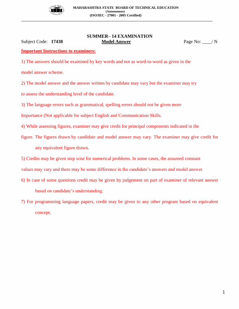
v) Draw block diagram of generation of FSK
Ans:- ( 2 mks)
MAHARASHTRA STATE BOARD OF TECHNICAL EDUCATION (Autonomous)
(ISO/IEC - 27001 - 2005 Certified)
__________________________________________________________________________________________________
3
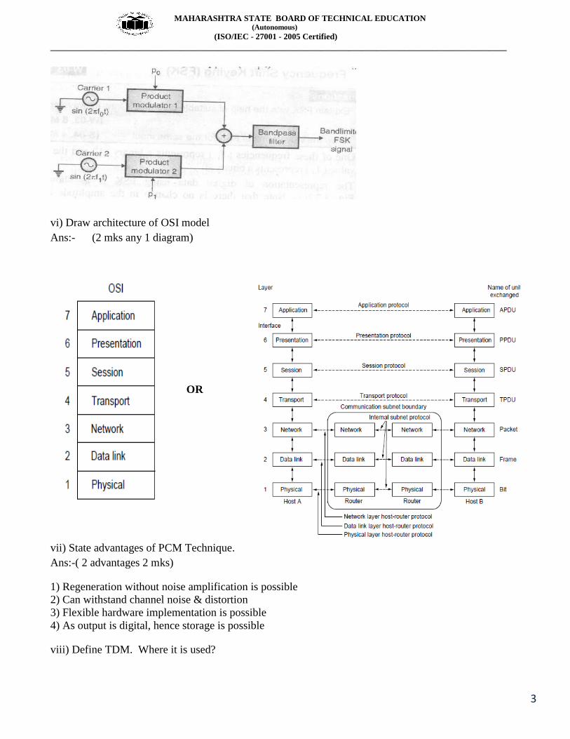
vi) Draw architecture of OSI model
Ans:- (2 mks any 1 diagram)
OR
vii) State advantages of PCM Technique.
Ans:-( 2 advantages 2 mks)
1) Regeneration without noise amplification is possible
2) Can withstand channel noise & distortion
3) Flexible hardware implementation is possible
4) As output is digital, hence storage is possible
viii) Define TDM. Where it is used?

MAHARASHTRA STATE BOARD OF TECHNICAL EDUCATION (Autonomous)
(ISO/IEC - 27001 - 2005 Certified)
__________________________________________________________________________________________________
4
Ans:-Time-division multiplexing (TDM) :- It is a process that allows several channels to share the entire
bandwidth of the link instead of sharing portion of bandwidth as in FDM.
( 1 mks)
Application:-1) Digital data transmission ( 2 applications 1 mks)
2) OFC data communication
b) Attempt any TWO of the following 08
i) Compare TDM ,FDM and WDM on following points. Definition, schematic diagram, advantages
and disadvantages.
Ans:-
Parameters TDM FDM WDM
Definition It is a process that
allows several
channels to
share the entire
bandwidth of the
link instead of
sharing portion
of bandwidth as
in FDM.
The process wherein
number of
signals can share
the bandwidth of
a common
communication
channel
WDM involves the
transmission of
multiple digital
signals using
several
wavelengths
without their
interfacing with
one another
OR
WDM is a technology
that enables
many optical
signals to be
transmitted
simultaneously
by a single fiber
cable.
Schemetic diagram - - -
Advatage ( any 1) In TDM the problem of
crosstalk is not
severe.
Synchronization is not
required.
It increases system
capacity and
ahannels having
different
frequency
ranges can be
multiplexed on a
long fibre.
Disadvantage( any 1) Synchronization is
required.
FDM suffers from the
problem of
Requires
synchronisation

MAHARASHTRA STATE BOARD OF TECHNICAL EDUCATION (Autonomous)
(ISO/IEC - 27001 - 2005 Certified)
__________________________________________________________________________________________________
5
crosstalk due to
imperfect band
pass filter
Diagrams-
TDM-
FDM-

MAHARASHTRA STATE BOARD OF TECHNICAL EDUCATION (Autonomous)
(ISO/IEC - 27001 - 2005 Certified)
__________________________________________________________________________________________________
6
WDM-
ii) Explain concept of cell pattern ,frequency rinse and cell splitting.
Ans:- ( Its frequency reuse and not frequency rinse)
Cell pattern- Defined as the geographical pattern when the electromagnetic radiation can be received
without creation interference in neighbouring region. For example the cell pattern is hexagonal
shaped as shown below-
( 1m ks)
Frequency reuse- Frequency reuse is the process in which the same set of frequencies (channels) can be
allocated to more than one cell. Provided the cells are separated by sufficient distance reducing
each cells coverage area invites frequency reuse cells using the same set of radio channels can
avoid mutual interference, provided they are properly separated. Each cell base station is
allocated a group of channel frequencies that are different from those of neighboring cells & base
station antennas are chosen to achieve a desired coverage pattern within its cell. However as long
as a coverage area is limited to within a cells boundaries the same group of channel frequencies
may be used in different cells without interfacing with each other provided the two cells are
sufficient distance from one another. ( 1 ½ mks)
Cell splitting-Each base station can handle particular maximum traffic but sometime traffic becomes
more than the capacity of the base station then cell splitting is done in cell splitting the cell is
divided in sub cells called microcell .for each microcell one cell site is allocated and height of

MAHARASHTRA STATE BOARD OF TECHNICAL EDUCATION (Autonomous)
(ISO/IEC - 27001 - 2005 Certified)
__________________________________________________________________________________________________
7
antenna is reduced accordingly . The frequency to each microcell is allocated depending on
principal of frequency reuse. ( 1 ½ mks)
iii) Explain synchronous and asynchronous modes of data transmission.
Ans:-
Synchronousmode:- In this mode of data transmission timing of sending data is not important i.e.
sender can send data any time.Sender and receiver firstly comes to agreement on size of data
likewise byte, start bit pattern, stop bit pattern. Data which is to be send is enclosed within
preamble of start bit pattern & ended with stop bit.Receiver when receives start bit it
synchronizes itself for receiving data. In addition to stop bit additional gap may be added to this
kind of system. After receiving N bits receiver searches for stop bit & after receiving stop bit
receiver waits for start bit of next data .This kind of communication is slower & has packet size
large but it is simple & cost affective.
( 1 mks)
( 1 mks)
Asynchronous mode:-In symmetric mode bit stream are combined frame .Single Frame may
contain multiple bytes. If size of data is smaller than size of frame then padding is done. In this
mode of transmission as there is no synchronization bit hence timing is important. It is faster &
within single frame we can send multiple bytes without requiring gap or overhead of
synchronization bits. ( 1 mks)
( 1 mks)

MAHARASHTRA STATE BOARD OF TECHNICAL EDUCATION (Autonomous)
(ISO/IEC - 27001 - 2005 Certified)
__________________________________________________________________________________________________
8
Q 2) Attempt any FOUR of the following 16
a) State meaning of following terms
i) Sectoring
ii) Segmentation & dualization
Ans:-Sectoring:- It is technique in which instead of using single Omni directional antenna multiple
directional antennas are used .Each of these directional antenna covers small area & this small
area is called as sector .sectoring reduce inter channel interfence Sectoring is used for improving
the signal to interference ratio which can result as smaller cluster size.
( 1 mks)
( 1 mks)
Segmentation & dualization:-Segmentation & dualization are the techniques incorporated when
additional cells are required within reuse distance. Segmentation divides group of channels into
smaller group of mutually exclusive frequencies .cell sites which are present in that reuse area
are assigned their own segment of channel group. Segmentation is used for avoiding co channel
interference. ( 1 mks)
Dualization is used for avoiding full cell splitting .Instead of dividing cell into 2 cell channels are
divided into 2 groups as busy channels (primary channels ) & free channels afterword free
channels are allocated to second logical cell.
(1 mks)
b) State the two advantages of pulse amplitude modulation over pulse width modulation.
Draw waveforms of PAM and PWM.
Ans:-Advantages:- ( any 2 ,2 mks)
1. Requires more bandwidth.
2.Has more waveform distortion
3. No need of synchronisation
PAM waveforms -1 mks

MAHARASHTRA STATE BOARD OF TECHNICAL EDUCATION (Autonomous)
(ISO/IEC - 27001 - 2005 Certified)
__________________________________________________________________________________________________
9
PWM waveforms -1 mks
c) Draw the block diagram and describe the working of mobile communication.
Ans:-( Diagram 2 mks,working 2 mks)

MAHARASHTRA STATE BOARD OF TECHNICAL EDUCATION (Autonomous)
(ISO/IEC - 27001 - 2005 Certified)
__________________________________________________________________________________________________
10
Explanation:- Fig shows a mobile or cellular telephone system that includes all the basic components necessary for
mobile communication.
The radio network is defined by a set of radio frequency transreceiver located within each of the cells.
The location of these radio frequency transreceivers are called base station
Base station: base station serves as central control for all users within that cell.
Mobile unit communicate directly with the base stations & the base stations communicate directly with
a mobile
Telephone switching office (MTSO):-An MTSO controls channel assignment, call processing, call
setup & call termination which includes signaling switching, supervision & allocating radio-frequency
channels. The MTSO provides a centralizes administration & maintenance point for the entire network
& interfaces with the public telephone network over wire line voice trunks & data links.
OR
Note :-Student can interpret block diagram in different way but it should consist basic blocks marks
should be given for that also.
d) Explain the following data encoding techniques unipolar NRZ,Polar NRZ and RZ.
Ans:-1) Unipolar NRZ:-It uses polarity. Logic 0 is represented by 0V and logic 1 is represented by a
constant signal level, say +v during its entire bit interval Tb.
2)Polar NRZ:-In this pulse of amplitude +A/2 of duration Tb is used to represent a logic 1 and a pulse of
amplitude –A/2 i of the same duration to represent logic 0.
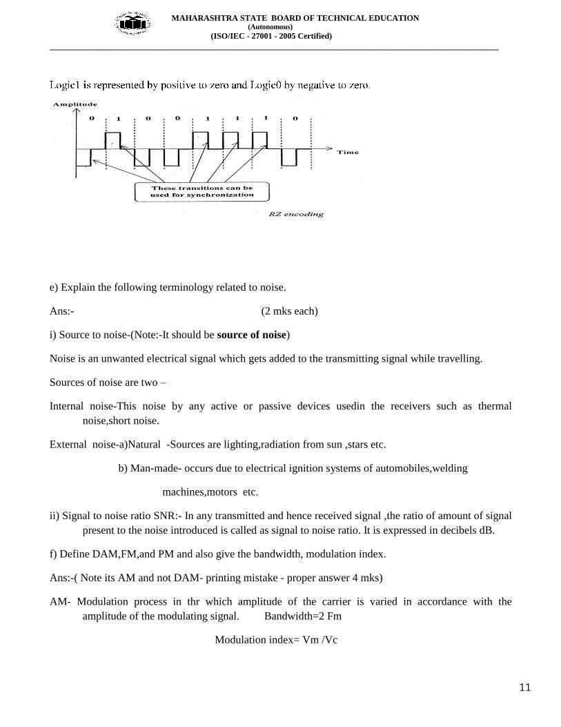
3) RZ (Return to Zero): 1mks
but during each bit. Unlike NRZ-L, half way through each bit interval the signal returns to zero.
MAHARASHTRA STATE BOARD OF TECHNICAL EDUCATION (Autonomous)
(ISO/IEC - 27001 - 2005 Certified)
__________________________________________________________________________________________________
11
e) Explain the following terminology related to noise.
Ans:- (2 mks each)
i) Source to noise-(Note:-It should be source of noise)
Noise is an unwanted electrical signal which gets added to the transmitting signal while travelling.
Sources of noise are two –
Internal noise-This noise by any active or passive devices usedin the receivers such as thermal
noise,short noise.
External noise-a)Natural -Sources are lighting,radiation from sun ,stars etc.
b) Man-made- occurs due to electrical ignition systems of automobiles,welding
machines,motors etc.
ii) Signal to noise ratio SNR:- In any transmitted and hence received signal ,the ratio of amount of signal
present to the noise introduced is called as signal to noise ratio. It is expressed in decibels dB.
f) Define DAM,FM,and PM and also give the bandwidth, modulation index.
Ans:-( Note its AM and not DAM- printing mistake - proper answer 4 mks)
AM- Modulation process in thr which amplitude of the carrier is varied in accordance with the
amplitude of the modulating signal. Bandwidth=2 Fm
Modulation index= Vm /Vc

MAHARASHTRA STATE BOARD OF TECHNICAL EDUCATION (Autonomous)
(ISO/IEC - 27001 - 2005 Certified)
__________________________________________________________________________________________________
12
AM waveforms
FM- Modulation process in which the frequency of the carrier is varied in accordance with the
amplitude of the modulating signal. Bandwidth=2( δ+ Fm)
Modulation index= δ/ Fm
FM waveforms
PM- Modulation process in which the phase of the carrier is varied in accordance with the amplitude of
the modulating signal.
Bandwidth=2( δ+ Fm) similar to FM ,considering frequency deviatio Modulation index= δ/ Fm
PM waveforms ( similar to FM)
(Waveforms are optional)

MAHARASHTRA STATE BOARD OF TECHNICAL EDUCATION (Autonomous)
(ISO/IEC - 27001 - 2005 Certified)
__________________________________________________________________________________________________
13
3.Attempt any FOUR of the following 16
a) How PPM is obtained from PWM?State any two advantages of PPM.
Ans:- ( 1 mks each diagram, 1 mks explaination, 1 mks advantages)
The block diagram of above fig. can be used for the generation of PWM as well as PPM.
A saw tooth generates a saw tooth signal frequency fs, therefore the saw tooth signal in this case
is a sampling signal. It is applied to the inverting terminal of the same comparator.
The modulating signal x(t) is applied to the non-inverting terminal of the same comparator.
The comparator output will remain high as long as the instantaneous amplitude of x(t) is higher
than that of the ramp signal.
This gives rise to a PWM signal at the comparator output as shown in waveform below.

MAHARASHTRA STATE BOARD OF TECHNICAL EDUCATION (Autonomous)
(ISO/IEC - 27001 - 2005 Certified)
__________________________________________________________________________________________________
14
The leading edges of PWM signal are always generated at fixed time instants. However the
occurrence of its trailing edges will be dependent on the instantaneous amplitude of x (t).
Therefore this PWM signal is said to be trail edge modulated PWM.
Advantages:- (any 2 points 1mks)
1.Transmitted power remains constant.
2.Immune to noise
b) Explain noise figure. What is ideal and practical value of noise figure? Why they are so?
Ans:- Noise Factor & noise figure are figures of merit used to indicate how much signal to noise ratio
deteriotes signal passes through circuit or series of circuits. Noise figure is noise factor stated in
dB and is parameter commonly used to indicate the quality of receiver .mathematically,
NF(db)=10log(input signal –to-noise power ratio)/(output signal –to-noise power ratio)
It indicates how much signal to noise ratio deteriorates as waveform propagates from input to output of
circuit . for perfect noiseless circuit noise figure is 0dB ( 1 mks)
Ideal noise figure:- if the amplifier is ideal & noiseless the input signal & noise e amplified the same &
signal –to-noise –ratio at output will equal the signal to noise ratio at input. ( 1
mks)
Practical Noise figure:- In real amplifier adds some internally generated noise to signal reducing
overall signal to noise ratio as signal passes through them .
(1 mks)
This difference between ideal and practical noise figure is because of the internal noise of the circuit or
receiver itself( due to components and internally generated noise. ( 1
mks)
c) Write step by step procedure for cellular call processing from mobile to mobile( cellular).
Ans:-Steps-
1The originating mobile unit initiates the call in same manner as it would for a mobile to wireline call.
2. The cell site controller receives caller identification number through reverse control channel which
are then forwarded to MTSO.
3 . The MTSO sends a page command to all cell site controllers to locate destination party ( which may
be anywhere in or out service area)
MAHARASHTRA STATE BOARD OF TECHNICAL EDUCATION (Autonomous)
(ISO/IEC - 27001 - 2005 Certified)
__________________________________________________________________________________________________
15
4. Once the destination mobile unit is located , the destination cell site controller sends page request
through control channel to destination party to determine of the unit is on or off hook.
5. After receiving a positive response to page , ideal user channels are assigned to both mobile units.
6. Call progress tones are applied in both the directions ( ring and ring back)
7. When the system receives the notice that called party has answered the call, the switches terminates
the call progress tone and conversation begins.
8. If mobile subscriber wishes to initiate a call and all user channels are busy, the switch sends directed
retry command instructing subscriber unit to reattempt the call through the neighboring cell.
9. If the system cannot allocate the user channels through a neighboring cell the switch transmits an
intercepts message to calling mobile unit over control channel.
10. If called party is off hook ,calling party receives busy signal.
11. If called number is invalid ,the calling party receives recorded message announcing that the call
cannot be processed.
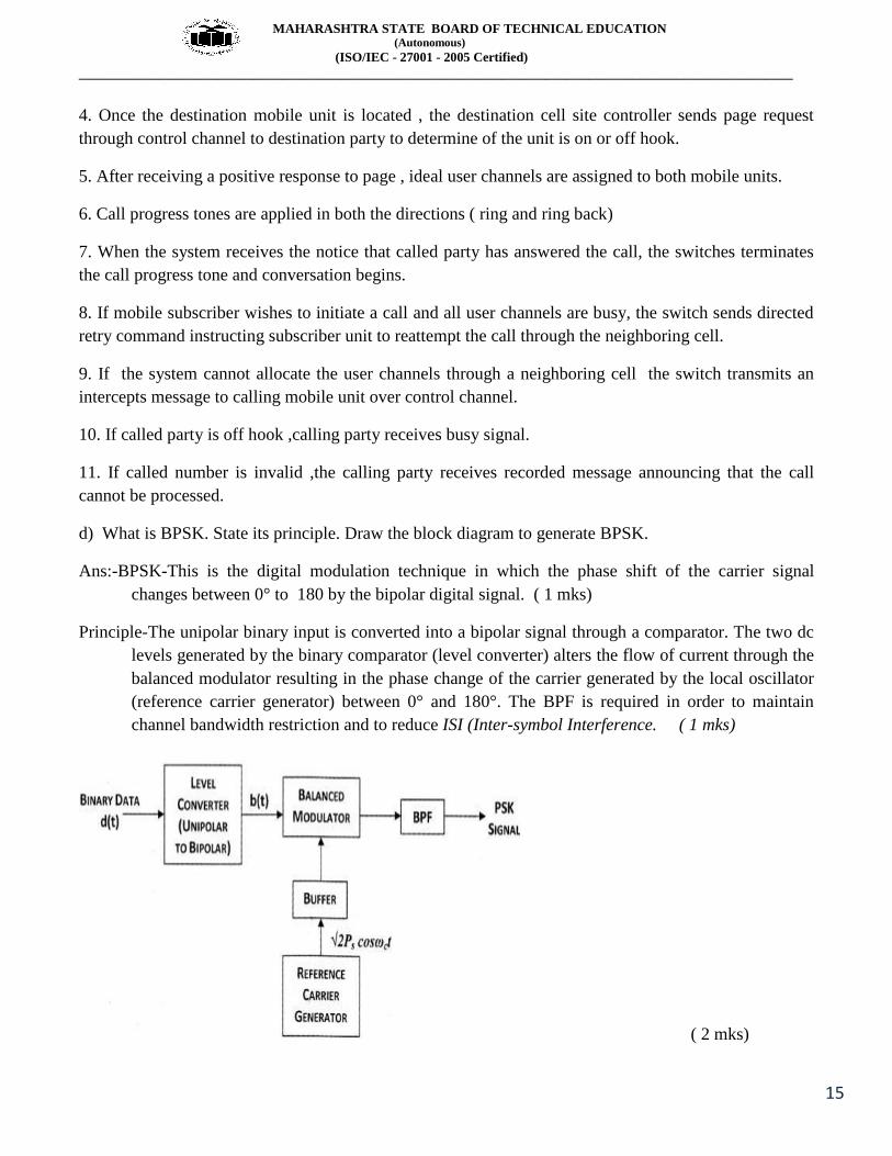
d) What is BPSK. State its principle. Draw the block diagram to generate BPSK.
Ans:-BPSK-This is the digital modulation technique in which the phase shift of the carrier signal
changes between 0° to 180 by the bipolar digital signal. ( 1 mks)
Principle-The unipolar binary input is converted into a bipolar signal through a comparator. The two dc
levels generated by the binary comparator (level converter) alters the flow of current through the
balanced modulator resulting in the phase change of the carrier generated by the local oscillator
(reference carrier generator) between 0° and 180°. The BPF is required in order to maintain
channel bandwidth restriction and to reduce ISI (Inter-symbol Interference. ( 1 mks)
( 2 mks)

MAHARASHTRA STATE BOARD OF TECHNICAL EDUCATION (Autonomous)
(ISO/IEC - 27001 - 2005 Certified)
__________________________________________________________________________________________________
16
e) Explain FM modulation circuit using varactor diode.
Ans:- ( diagram 2 mks, explanation 2 mks)
A varactor diode is a semi-conductor diode whose junction capacitance varies linearly with the applied
bias, and it must be reversed biased by a negative dc source.
The modulating AF voltage appears in series with the negative supply voltage. So the voltage applied
varies in proportion with the modulating voltage , varying junction capacitance of the varactor
diode. The diode is in parallel with the oscillator tuned circuit, so oscillator frequency will
change with the varactor diode capacitance and FM wave is produced. The RFC will connect the
DC and modulating signal to the varactor diode but offers a very high impedance at high
oscillator frequency. So the oscillator circuit is isolated from the dc bias and modulating signal.
f) State the basic concept of the following.
Ans:-(2 mks each)
i) Telesurgery-Telesurgery does not exactly means doing surgery remotely .It is classified into two
categories namely telemetering &telepresence .In telemetering surgeon present near patient
performs surgery in consultation with distant specialist & expert surgeon .telemetering is also
used for trading to student remotely who can observe surgery remotely .Telepresence
surgeryused to perform micro procedure such as vascular repair & laser retinal surgery
ii) Tele psychiatry-It involves providing psychiatric theory remotely .It involves spoken conversation
between consultant & patient but does not involves transmission of any test data Real time video
conferencing is used for tele psychiatry.
4. Attempt any FOUR of the following
16

MAHARASHTRA STATE BOARD OF TECHNICAL EDUCATION (Autonomous)
(ISO/IEC - 27001 - 2005 Certified)
__________________________________________________________________________________________________
17
a) Explain Manchester and differential manchester data encoding techniques.
Ans:-Explain 1 mks each and 1 waveform- 1mks each
Manchester- In this data encoding, a negative to positive transition represents bit 1 and a positive to
negative represents bit 0 at the middle of bit period Tb.
Differential Manchester- In this encoding the binary bit 0 is represented as presence of transition at the
middle of Tb from 0-1 while alternate 1 are represented as transition from 0-1 and 1-0 levels
b) Draw the block diagram of delta modulationand describe its working principle.
Ans:-( diagram 2 mks, working 2 mks)
MAHARASHTRA STATE BOARD OF TECHNICAL EDUCATION (Autonomous)
(ISO/IEC - 27001 - 2005 Certified)
__________________________________________________________________________________________________
18
In figure above, the input analog is sampled and converted to PAM signal, which is compared
with the output of DAC. The output of DAC is a voltage equal to regenerated magnitude of the
previous sample, which was stored in the up-down counter as a binary number. The up-down
counter is incremented or decremented depending on whether the previous sample is larger or
smaller than the current sample. The up-down counter is clocked at a rate equal to the sample
rate. Therefore up-down counter is updated after each comparison..Initially, the up-down counter
is zeroed, and the DAC is outputting 0V. The first sample is taken, converted to a PAM signal,
and compared with zero volts.
The output of comparator is a logic 1 condition (+V), indicating that the current sample is larger
in amplitude than the previous sample. On the next clock pulse, the up-down counter is
incremented to count of 1. The DAC now outputs a voltage equal to the magnitude of the
minimum step size (resolution).With the input signal shown, the up-down counter follows the
input analog signal up until the output of the DAC exceed the analog sample; then the up-down
counter will begin counting down until the output of DAC drops below the sample amplitude
c) State the meaning of terms
Ans:- ( 1 mks each)
i) Digital signature:- Digital signature is an electronic signature that can be used to authenticate the
identity of the sender of a message or the signer of a document, and possibly to ensure that the original
content of the message or document that has been sent is unchanged.
ii) Message confidentiality:- It is concept related to protecting message while transmission. Two or
more hosts communicate securely, typically using encryption. The communication cannot be
monitored (sniffed) by untrusted hosts. The communication between trusted parties is
confidential
iii) Integrity—The assurance to an entity that data has not been altered (intentionally or unintentionally)
between "there" and "here," or between "then" and "now."
iv) Authentication—The assurance to one entity that another entity is who he/she/it claims to be.
d) Describe the concept of routers and gateways.
Ans:- ( 2 mks each)
Router:
Router is a device that connects two or more networks. It consists of a combination of hardware and
software.
1) A router is a specialized computer connected to more than one n/w
2) Router operate at the n/w layer

MAHARASHTRA STATE BOARD OF TECHNICAL EDUCATION (Autonomous)
(ISO/IEC - 27001 - 2005 Certified)
__________________________________________________________________________________________________
19
3) The primary function of a router is to connect n/w together & keep layer 2 broadcast traffic under
control.
4) A router is typical connected to at least two n/w commonly two LAN OR WAN or LAN and its ISP s
n/w or more n/w connect.
5) Routers are located at gateways, the places where two or more n/w connect.
Types of Router
1) Static
2) Dynamic
Gateway:
It is a device which connects two different dissimilar networks which has similar function of
communication. It is also called as protocol convertor. It works in all layers of OSI model.
Gateway operates at all 7 layers of the OSI model. It is a device, which connects two dissimilar n/w
which have same function of communication. Situation wheregateways are necessary for
different n/w like Ethernet, Token Ring, and FDDI etc. It can communicate if they are using
same protocol for communication like TCP/IP 08 Apple talk if they are using different protocol
from a gateway cash forward packet across different n/w s that may also use different protocol.
Eg: if n/w A is a Token Ring network using TCP/IP & network B is a Novell Network, a
gateway can relay frames between two. This means that a gateway has not only had, but also
between different protocols. In certain situations the only changes required are to the frame
header. In other cases, the gateway must take case of different frame sizes, data rates, format,
acknowledgement schemes, and priority schemes etc.
e) Draw the block diagram and describe the working of single channel bioelemetry system for ECG.
Ans:- ( diagram 2 mks, explanation 2 mks)
It consist of mainly two parts namely telemetry transmitter & telemetry receiver .
MAHARASHTRA STATE BOARD OF TECHNICAL EDUCATION (Autonomous)
(ISO/IEC - 27001 - 2005 Certified)
__________________________________________________________________________________________________
20
Transmitter:- signals picked up by pre gelled electrodes are amplified & modulated at frequency of 1
KHz. It is again modulated to UHF frequency. The resulting signal is radiated with of electrode lead
(RL) which works as antenna .
Receiver – it uses unidirectional quarter wave monopole receiving antenna which receives signals
.These signals are in turn fed to RF amplifier RF amplifier which performs RF filtering &image
frequency rejection & it prevents cross coupling .The output of RF amplifier is fed to demodulator
.demodulator demodulates signal & it is provided to ECG filter
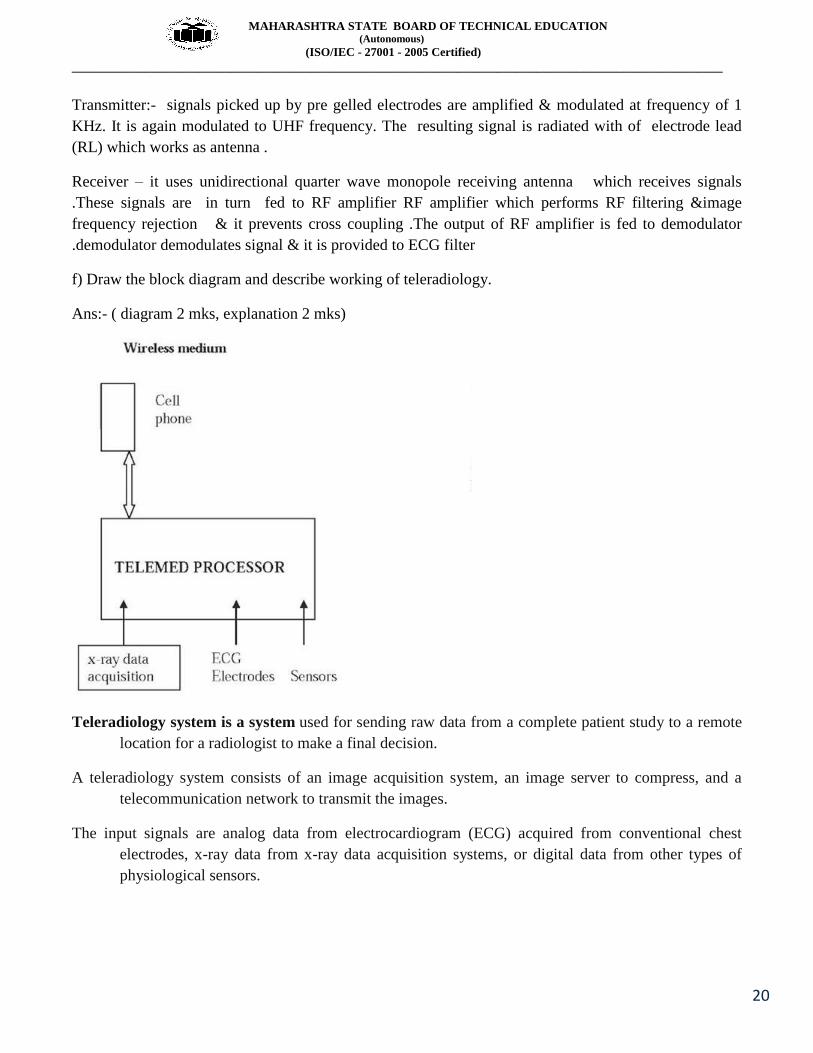
f) Draw the block diagram and describe working of teleradiology.
Ans:- ( diagram 2 mks, explanation 2 mks)
Teleradiology system is a system used for sending raw data from a complete patient study to a remote
location for a radiologist to make a final decision.
A teleradiology system consists of an image acquisition system, an image server to compress, and a
telecommunication network to transmit the images.
The input signals are analog data from electrocardiogram (ECG) acquired from conventional chest
electrodes, x-ray data from x-ray data acquisition systems, or digital data from other types of
physiological sensors.

MAHARASHTRA STATE BOARD OF TECHNICAL EDUCATION (Autonomous)
(ISO/IEC - 27001 - 2005 Certified)
__________________________________________________________________________________________________
21
The processor is a computer that can have any amount of memory. Since the signals are from many
channels, multiplexing is done to send the desired signal based on a priority scheme in a
particular time instant.
Signals from the telephone are transmitted.
Q5. Attempt any FOUR of the following 16
a) Explain the concept and operating of hubs repeaters.
Ans:- Hub is amplifying & splitting device .Hub contains multiple ports & is a common connection
point for connecting all segments of a LAN. When a packet arrives on a port, it is forwarded to rest of
ports so that it can be sent to all other nodes in the network. Types of Hub:-
1) Active Hub
2) Passive Hub
3) Intelligent hub
Operation :- A hub has a number of input lines that it joins electrically. Frames arriving on any of the
lines are sent out on all the others. If two frames arrive at the same time, they will collide, just as on a
coaxial cable. In other words, the entire hub forms a single collision domain. All the lines coming into a
hub must operate at the same speed. Hubs differ from repeaters in that they do not (usually) amplify the
incoming signals and are designed to hold multiple line cards each with multiple inputs, but the
differences are slight. Like repeaters, hubs do not examine the 802 addresses or use them in any way.
Repeaters -As signals travel along a cable, they degrade and become distorted in a process called
"attenuation." If a cable is long enough, attenuation will finally make a signal unrecognizable. Installing
a repeater enables signals to travel farther. A repeater is a physical layer device. It receives, amplifies
(regenerates), and retransmits signals in both directions.
Operation- :-A repeater works at the physical layer of the OSI Reference Model to regenerate the
network's signals and resend them out on other segments. Figure shows how repeaters regenerate weak
signals. Repeaters regenerate weak signals. The repeater takes a weak signal from one segment,

MAHARASHTRA STATE BOARD OF TECHNICAL EDUCATION (Autonomous)
(ISO/IEC - 27001 - 2005 Certified)
__________________________________________________________________________________________________
22
regenerates it, and passes it to the next segment. to pass data through the repeater from one segment to
the next. Regenerate the signal to increase the distance transmitted.
b) Compare mesh and star topology with respect to i) arrangements of nodes ii) standards used
Ans:-
Star topology
Mesh topology
All computers/devices present on network
connect to a central connecting device
by using separate cable running from
that computer to central connecting
device called hub or switch.
In this topology there is separate line between
every station to all stations present on
network .
IEEE 802.3 is an IEEE amendment for
Ethernet using Hub
IEEE 802.11s is an IEEE 802.11 amendment
for mesh networking
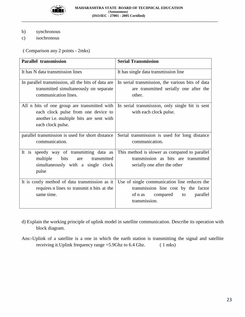
c) What are different type of transmission. Compare parallel & serial transmission.
Ans:- Type of data transmission are ( 2 mks)
i) Parallel
ii) serial
a) Asynchronous
MAHARASHTRA STATE BOARD OF TECHNICAL EDUCATION (Autonomous)
(ISO/IEC - 27001 - 2005 Certified)
__________________________________________________________________________________________________
23
b) synchronous
c) isochronous
( Comparison any 2 points - 2mks)
Parallel transmission Serial Transmission
It has N data transmission lines It has single data transmission line
In parallel transmission, all the bits of data are
transmitted simultaneously on separate
communication lines.
In serial transmission, the various bits of data
are transmitted serially one after the
other.
All n bits of one group are transmitted with
each clock pulse from one device to
another i.e. multiple bits are sent with
each clock pulse.
In serial transmission, only single bit is sent
with each clock pulse.
parallel transmission is used for short distance
communication.
Serial transmission is used for long distance
communication.
It is speedy way of transmitting data as
multiple bits are transmitted
simultaneously with a single clock
pulse
This method is slower as compared to parallel
transmission as bits are transmitted
serially one after the other
It is costly method of data transmission as it
requires n lines to transmit n bits at the
same time.
Use of single communication line reduces the
transmission line cost by the factor
of n as compared to parallel
transmission.
d) Explain the working principle of uplink model in satellite communication. Describe its operation with
block diagram.
Ans:-Uplink of a satellite is a one in which the earth station is transmitting the signal and satellite
receiving it.Uplink frequency range =5.9Ghz to 6.4 Ghz. ( 1 mks)

MAHARASHTRA STATE BOARD OF TECHNICAL EDUCATION (Autonomous)
(ISO/IEC - 27001 - 2005 Certified)
__________________________________________________________________________________________________
24
( 2 mks)
As seen from the block diagram of the uplink model the base band signal is modulated ,passed through
selective filters . The signal is frequency up converted using mixer and passed through high
power amplifier and then radiated towards the satellite using high gain narrow beam width dish
antenna.
( 1 mks)
e) Write four advantages & disadvantage of Bus & Ring topology.
Ans:-( any 2 advantages and disadvantages can also be given marks)
Bus topology:-
Advantages( 2 points- 1 mks)
easy to install
requires less cables comparing with Mesh topology
cost of installation is easy
any device can initiate data transmission
adding node within particular limit is easy
Disadvantage ( 2 points- 1 mks)
There is a limit on central cable length and number of nodes that can be connected.
It is difficult to detect and troubleshoot fault at individual station.
Maintenance costs can get higher with time.
Efficiency of Bus network reduces, as the number of devices connected to it increases.
Ring Topology:-

MAHARASHTRA STATE BOARD OF TECHNICAL EDUCATION (Autonomous)
(ISO/IEC - 27001 - 2005 Certified)
__________________________________________________________________________________________________
25
Advantages ( 2 points- 1 mks)
Every node send the data when it receives an empty token this reduces chances of collision.
Also in ring topology all the traffic flows in only one direction at very high speed.
Even when the load on the network increases, its performance is better than that of Bus topology.
There is no need for network server to control the connectivity between workstations.
Additional components do not affect the performance of network.
Each computer has equal access to resources.
Disadvantages ( 2 points- 1 mks)
Each packet of data must pass through all the computers between source and destination. This
makes it slower than Star topology.
If one workstation or port goes down, the entire network gets affected.
Network is highly dependent on the wire which connects different components.
MAU’s and network cards are expensive as compared to Ethernet cards and hubs.
f) Draw the block diagram of telecardiology and describe its working.
Ans:- ( 2 mks diagram,2 mks explanation)

MAHARASHTRA STATE BOARD OF TECHNICAL EDUCATION (Autonomous)
(ISO/IEC - 27001 - 2005 Certified)
__________________________________________________________________________________________________
26
Teleradiology system is a system used for sending raw data from a complete patient study to a remote
location for a radiologist to make a final decision.
A teleradiology system consists of an image acquisition system, an image server to compress, and a
telecommunication network to transmit the images.
The input signals are analog data from electrocardiogram (ECG) acquired from conventional chest
electrodes, x-ray data from x-ray data acquisition systems, or digital data from other types of
physiological sensors.
The processor is a computer that can have any amount of memory. Since the signals are from many
channels, multiplexing is done to send the desired signal based on a priority scheme in a particular time
instant.
Signals from the telephone are transmitted.
Q6. Attempt any FOUR of the following 16
a) What are the different types of satellite orbits. What is geostationary satellite.?
Ans:-There are three common orbital patterns used in satellite communication:
1. Polar orbit: A satellite orbit in which the satellite passes over the North and South poles on each orbit,
and eventually passes over all points on the earth. The angle of inclination between the equator
and a polar orbit is 90 degrees.
2. Inclined orbit: A satellite is said to occupy an inclined orbit around the Earth if the orbit exhibits an
angle other than zero degrees with the equatorial plane.
3. Equatorial orbit: A satellite in equatorial orbit flies along the line of the Earth's equator. To get into
equatorial orbit, a satellite must be launched from a place on Earth close to the equator.( 3 mks)
Geostationary satellite-A satellite moving in the equatorial orbit at the height of 35786 km above the
earth in synchro with revolution of the earth, thus appearing to be stationery at a particular point
from the earth. ( 1 mks)
b) Draw block diagram of adaptive delta modulation and describe its working.
Ans:- Adaptive delta modulation

MAHARASHTRA STATE BOARD OF TECHNICAL EDUCATION (Autonomous)
(ISO/IEC - 27001 - 2005 Certified)
__________________________________________________________________________________________________
27
(2 mks)
Initially analog signal is applied to sample & hold circuit which converts analog signal to time discrete
PAM. The PAM o/p of sample & hold is applied along with analog converted ADM signal
which specifies value of previous step . To reduce granular noise & step overload the Digital
processor either increases or decreases step size by increasing or decreasing counter value. The
o/p of processor is fed to digital to analog convertor which converts digital data to pulse &these
pulse are applied to comparator as second input .As shown in the figure below,the stepsize
changes as per the slope of the modulating signal and hence called as Adaptive delta modulation.
( 2 mks)
c) Draw the block diagram of satellite communication. State the frequency bands used in satellite
communication.
Ans:-( block diagram 2 mks, any 4 frequency bands 2 mks)
Frequency Band C-Band
MAHARASHTRA STATE BOARD OF TECHNICAL EDUCATION (Autonomous)
(ISO/IEC - 27001 - 2005 Certified)
__________________________________________________________________________________________________
28
X-Band
Ku-Band
Ka-Band
(Commercial)
Ka-Band
(Military)
d) A voice signal of telephone ( 0 to 4 Khz) is to be digitized using PCM.
Cal- i) Nyquist rate, ii) No of quantization levels to encode each sample into 7 bits ASCII code.
Ans:- Given data-
Bandwidth- 0 to 4 Khz,So max Frequency Fmax= 4 Khz
So Nyquist rate=2 Fmax=8Khz. ( 2 mks)
Quantization levels Q=2n
27
= 128 levels ( 2 mks)
e) State 4 advantage and disadvantages of FDMA and CDMA.
Ans:- ( Note – Actually 2 advantages and disadvantages are enough for each FDMA and CDMA)
FDMA-
Advantages ( any 2 -1 mks)
1.Synchronisation is not required.
2. Overall bandwidth is shared among many stations
Disadvantages-( any 2 – 1 mks)
1. theproblem of crosstalk
2. the data transmission speed is less
CDMA-
Advantages ( any 2 -1 mks)

MAHARASHTRA STATE BOARD OF TECHNICAL EDUCATION (Autonomous)
(ISO/IEC - 27001 - 2005 Certified)
__________________________________________________________________________________________________
29
1. It combats the intentional interference (jamming) and the unintentional interference from some other
user
2. To avoid the self interference due to multipath propagation
3. Hides a signal by transmitting it at a low power and thus making it difficult for an unintended listener
to detect in the presence of background noise.
4. Achieves message privacy in the presence of other listeners
Disadvantages-( any 2 – 1 mks)
1) Reduce efficiency due to coding
2) synchronization & precise timing is required
f) State the working principle of ASK. State its advantages and disadvantages.
Ans:- ( Diagram 1 mks, explanation 1 mks)
The ASK signal cab be transmitted
VASK(t) = dsin(2πfct)
VASK(t) = sin(2πfct) where d =1
VASK(t) = 0 where d =0
Where d = data bit (data bit either 0 or 1)
Explanation : ASK is the digital carrier modulation in in which the amplitude of sinusoidal carrier will
take one of two predetermined values in response to 0 or 1 value of digital input signal.
The bandwidth of ASK signal is dependent on the bit rate Fb where bit rate Fb = 1/Tb as shown in
diagram.
MAHARASHTRA STATE BOARD OF TECHNICAL EDUCATION (Autonomous)
(ISO/IEC - 27001 - 2005 Certified)
__________________________________________________________________________________________________
30
The maximum bandwidth of ASK signal is
Bandwidth = 2 Fb
Advantages:- ( any 2 ,1 mks)
1.Easy to generate and hence detect
2.Simple circuit.
Disadvantages-( any 2 ,1 mks)
1.Poor noise immunity
2.Data transmission at low bit rate