summer 15 examination - msbte study...
TRANSCRIPT

MAHARASHTRA STATE BOARD OF TECHNICAL EDUCATION
(Autonomous)
(ISO/IEC - 27001 - 2005 Certified)
____________________________________________________________________________________
Page 1 of 27
SUMMER– 15 EXAMINATION
Subject Code: 17317 Model Answer
Important Instructions to examiners:
1) The answers should be examined by key words and not as word-to-word as given in the
model answer scheme.
2) The model answer and the answer written by candidate may vary but the examiner may try
to assess the understanding level of the candidate.
3) The language errors such as grammatical, spelling errors should not be given more
Importance (Not applicable for subject English and Communication Skills.
4) While assessing figures, examiner may give credit for principal components indicated in the
figure. The figures drawn by candidate and model answer may vary. The examiner may give
credit for any equivalent figure drawn.
5) Credits may be given step wise for numerical problems. In some cases, the assumed constant
values may vary and there may be some difference in the candidate’s answers and model answer.
6) In case of some questions credit may be given by judgement on part of examiner of relevant
answer based on candidate’s understanding.
7) For programming language papers, credit may be given to any other program based on
equivalent concept.

MAHARASHTRA STATE BOARD OF TECHNICAL EDUCATION
(Autonomous)
(ISO/IEC - 27001 - 2005 Certified)
____________________________________________________________________________________
Page 2 of 27
1. A) Attempt any six of the following: 12 marks
a. Define the terms:
i. Resolution ii. Dead Zone
Ans a. Each Definition: 1M
i. Resolution: the smallest change in input to which instrument can respond is known as
resolution.
ii. Dead zone: the largest range of value of measured variable to which instrument does
not respond is known as dead zone.
b. Draw a circuit diagram of universal shunt voltmeter.
Ans b. Circuit diagram: 2M
c. State any two disadvantages of digital instruments.
Ans c. Any two disadvantages: 2M
i. They are costly.
ii. They are complex in nature.
iii. Speed of operation is limited due to digitizing circuits.
d. State principle of digital frequency meter.
Ans d. Principle: 2M
The single waveform is converted to trigger pulse and applied continuously to AND gate. A
pulse of 1sec is applied to the other terminal and the number of pulses counted during this period
indicates the frequency. The signal whose frequency is to be measured is converted into train of
pulses, one pulse for each cycle of the signal. the number of pulses occurring in a definite
interval of time is then counted by an electronic counter since each pulse represents the cycle of
the unknown signal, the number of counts is the direct indication of the frequency of the signal
since electronic counters have a high speed of operation, high frequency signal can be measured.
e. Explain in brief function of focusing and accelerating anodes in CRT.
Ans e. correct function – 2 marks
The assembly of focusing and accelerating anodes is used to control the scattering of electrons
and increase in speed of electrons.
It consists of pre-accelerating anode and accelerating anode.

MAHARASHTRA STATE BOARD OF TECHNICAL EDUCATION
(Autonomous)
(ISO/IEC - 27001 - 2005 Certified)
____________________________________________________________________________________
Page 3 of 27
The focusing anode is placed between the pre-accelerating anode and accelerating anode.
When the electron beam is accelerated by the accelerating anodes it passes through the deflection
plate assembly.
f. Draw a block diagram of vertical deflection system in CRO.
Ans f. Block diagram: 2M
g. State need of signal generators.
Ans g. Any two points: 2M
1. To produced controlled output waveform for testing.
2. To provide small signal with desired frequency and amplitude.
h. List one example of time domain and frequency domain instruments.
Ans h. Example of time domain: 1M and Example of frequency domain: 1M
Time domain instruments: CRO
Frequency domain instruments: Spectrum analyser
B) Attempt any two of the following: 8 marks
a. List dynamic characteristics of instruments. Define any two.
Ans a. (list any four – 2 marks, definition any two – 1 mark each)
Dynamic characteristics of instruments are:
1. Speed of response
2. Fidelity
3. Lag
4. Dynamic error.
MAHARASHTRA STATE BOARD OF TECHNICAL EDUCATION
(Autonomous)
(ISO/IEC - 27001 - 2005 Certified)
____________________________________________________________________________________
Page 4 of 27
Definition:
1. Speed of response:
The rapidity with which instrument responds to make changes in the measured quantity is called
as speed of response.
2. Fidelity:
The degree to which instrument indicates the change in measured variable without dynamic error
is called as fidelity.
3. Lag:
The retardation on delay in the response of an instrument to make the change in measure quantity
is known as lag.
4. Dynamic error:
The difference between the true value of a quantity changing with time and the value indicated
by the instrument if no static error is assumed is called as dynamic error.
b. Describe the different standards.
Ans b. 4Marks
1) International standards:
International standards are fixed and develop by international agreement.
These standards are maintained at International Bureau of Weights and Measures in
France. This standard gives different unit having best accuracy.
To preserve best accuracy these standards are periodically check by absolute measurement.
These standards are used to calibrate primary standard only.
These are not available to ordinary user for measurement.
2) Primary standards
These standards are preserved and maintained by National Standard Laboratories
which are located at different part of the world. E.g.-NBS (National Bureau of Standards)
located at Washington. These standards are periodically calibrated by International standards.
3) Secondary standards
These standards are also called as basic standards.
These standards are used by industries and calibration laboratories.
Each industry has its own laboratory.
4) Working standards
These standards are used in general laboratories.
These standards are used to check components and calibrating laboratory instruments to
achieve good accuracy and better performance.

MAHARASHTRA STATE BOARD OF TECHNICAL EDUCATION
(Autonomous)
(ISO/IEC - 27001 - 2005 Certified)
____________________________________________________________________________________
Page 5 of 27
c. Draw a diagram of D’ Arsonval movement and state its principle.
Ans c. Diagram:2M, Principle:2M
Working Principle:-
A current carrying conductor placed in magnetic field experiences a force.
It is given by the expression,
F = BIL
Where,
F= Force in Newton
B= Flux density in Tesla
I= Current in ampere
L= Length of conductor in meter.
2. Attempt any four of the following: 16 marks
a. Explain the need of calibration and calibration process.
Ans a.
Calibration: 2M
The process of deriving the value of a quantity by comparing that quantity with a standard
quantity is called as calibration.
Calibration of instrument is done to obtain correct unknown value of each scale reading on
measuring instrument.
Need of calibration 2M
There are 3 main reasons for having instrument calibration:
1. To ensure reading from an instrument are consistent with other measurements.
2. To determine the accuracy of the instrument reading.
3. To establish the reliability of the instrument i.e. it can be trusted.
MAHARASHTRA STATE BOARD OF TECHNICAL EDUCATION
(Autonomous)
(ISO/IEC - 27001 - 2005 Certified)
____________________________________________________________________________________
Page 6 of 27
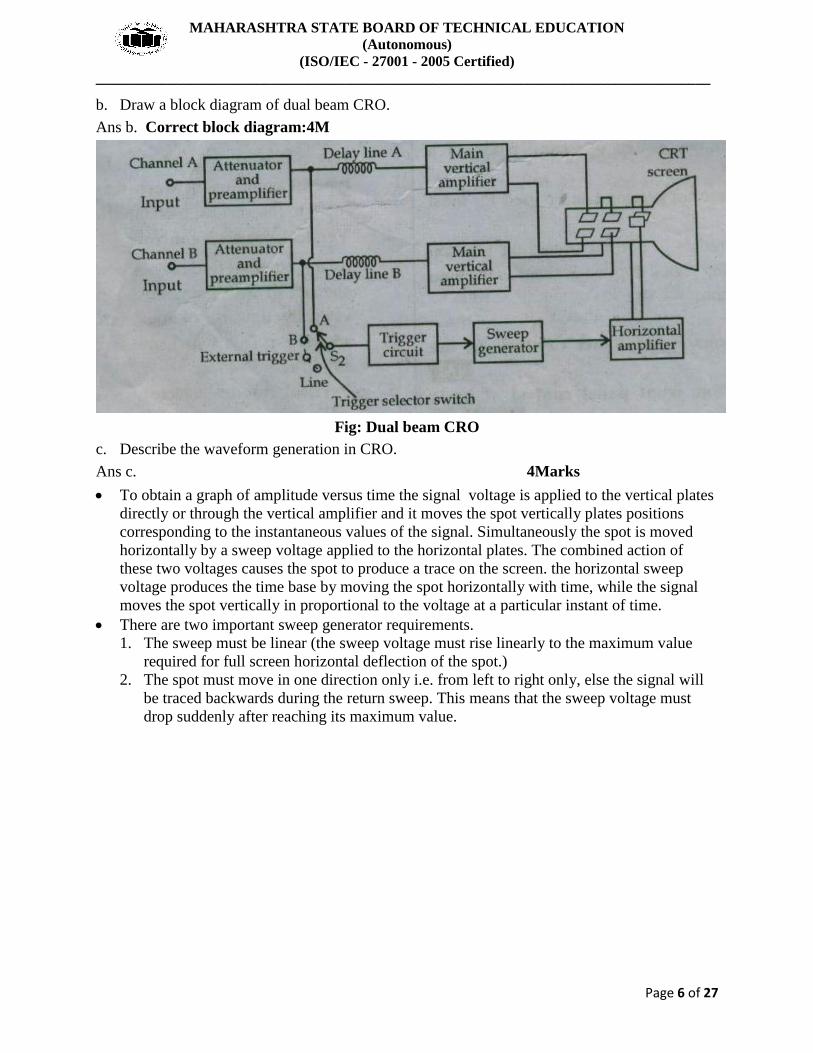
b. Draw a block diagram of dual beam CRO.
Ans b. Correct block diagram:4M
Fig: Dual beam CRO
c. Describe the waveform generation in CRO.
Ans c. 4Marks
To obtain a graph of amplitude versus time the signal voltage is applied to the vertical plates
directly or through the vertical amplifier and it moves the spot vertically plates positions
corresponding to the instantaneous values of the signal. Simultaneously the spot is moved
horizontally by a sweep voltage applied to the horizontal plates. The combined action of
these two voltages causes the spot to produce a trace on the screen. the horizontal sweep
voltage produces the time base by moving the spot horizontally with time, while the signal
moves the spot vertically in proportional to the voltage at a particular instant of time.
There are two important sweep generator requirements.
1. The sweep must be linear (the sweep voltage must rise linearly to the maximum value
required for full screen horizontal deflection of the spot.)
2. The spot must move in one direction only i.e. from left to right only, else the signal will
be traced backwards during the return sweep. This means that the sweep voltage must
drop suddenly after reaching its maximum value.

MAHARASHTRA STATE BOARD OF TECHNICAL EDUCATION
(Autonomous)
(ISO/IEC - 27001 - 2005 Certified)
____________________________________________________________________________________
Page 7 of 27
d. Draw a circuit of time base generator and explain it.
Ans d. Diagram:2M; Explaination:2M
Time base generator:
The main purpose of time base generator is to convert given input signal into sawtooth
waveform, which will deflect the beam in the horizontal direction.
It has two modes i.e. sweep mode and fly back mode.
During sweep time TS the beam moves left to tight across the CRT.
The beam is deflected towards right by increasing amplitude of ramp voltage and the fact that
positive voltage attracts the negative electrons.

MAHARASHTRA STATE BOARD OF TECHNICAL EDUCATION
(Autonomous)
(ISO/IEC - 27001 - 2005 Certified)
____________________________________________________________________________________
Page 8 of 27
During retrace time or fly back time Tr the beam returns quickly to the left side of screen.
The control grid is generally gated OFF which black out the beam during retrace time and
prevent an undesirable retrace pattern from appearing on the screen.
e. Explain operation of dual trace CRO, with neat block diagram.
Ans e. Operation:2M; Block diagram:2M
Fig: Dual trace CRO
The block diagram of dual trace CRO is shown above.
In this type of CRO a single beam is split into two to produce two changes.
It consists of single electronic gun CRT, electronic switch, vertical amplifier, delay line,
trigger circuit, sweep generator, horizontal amplifier, two attenuator and preamplifier.
The dual trace CRO has two separate vertical input, channel A and channel B.
These two channels are used to separate attenuator and pre amplifier stage which is
controlled individually.
An electronic switch is used to pass one channel at a time into vertical amplifier through
delay line.
Trigger selector switch: Trigger signals are picked up from channel A or channel B or line or
external signal.
In circuit there are three switches used. The switch S1 is used to select the channel A or
channel B to connect with vertical amplifier. Switch S2 allows trigger circuit to select
channel A, channel B, line or external signal. While switch S3 is used to connect horizontal
amplifier to channel B in X- Y mode.
MAHARASHTRA STATE BOARD OF TECHNICAL EDUCATION
(Autonomous)
(ISO/IEC - 27001 - 2005 Certified)
____________________________________________________________________________________
Page 9 of 27
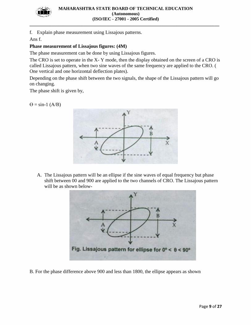
f. Explain phase measurement using Lissajous patterns.
Ans f.
Phase measurement of Lissajous figures: (4M)
The phase measurement can be done by using Lissajous figures.
The CRO is set to operate in the X- Y mode, then the display obtained on the screen of a CRO is
called Lissajous pattern, when two sine waves of the same frequency are applied to the CRO. (
One vertical and one horizontal deflection plates).
Depending on the phase shift between the two signals, the shape of the Lissajous pattern will go
on changing.
The phase shift is given by,
Ө = sin-1 (A/B)
A. The Lissajous pattern will be an ellipse if the sine waves of equal frequency but phase
shift between 00 and 900 are applied to the two channels of CRO. The Lissajous pattern
will be as shown below-
B. For the phase difference above 900 and less than 1800, the ellipse appears as shown

MAHARASHTRA STATE BOARD OF TECHNICAL EDUCATION
(Autonomous)
(ISO/IEC - 27001 - 2005 Certified)
____________________________________________________________________________________
Page 10 of 27
C. Different Lissajous figure for phase difference 00, 450, 900, 1350, 1800, 2250, 2700, 3150,
3600 are shown below respectively
3. Attempt any four of the following: 16 marks
a. State detailed classification of errors.
Ans a.
4Marks
1. Static error :
The error which occurs in stationary condition is called as static error. These are classified as:
i. Gross errors: the errors which occur due to human mistakes while taking reading, handling
instrument incorrect setting or adjustment and improper use of instrument are known as gross
errors. The complete elimination of gross errors is not possible but we can minimize it. These
errors are also called as personal errors. These errors may be avoided by taking reading and
recording it carefully, by taking more than two reading, by proper handing of instrument.

MAHARASHTRA STATE BOARD OF TECHNICAL EDUCATION
(Autonomous)
(ISO/IEC - 27001 - 2005 Certified)
____________________________________________________________________________________
Page 11 of 27
ii. Systematic errors: these errors occur due to shortcoming of the instrument such as
defective or worn part or aging or effect of environment on the instrument.
a. Instrumental error: the errors which arise due to inherent shortcoming of instrument,
misuse of instrument, loading effect of instrument are called as instrumental error. These
errors can be removed by, selecting suitable instrument for particular application,
selection of correct setting on the instrument, calibrating the instrument against standard,
applying correction factor after the determination of instrumental error.
b. Environmental error: these errors occur due to external condition to the measuring
instrument, such as temperature, pressure, humidity, dust and external magnetic field.
This error can be avoided by, keeping surrounding condition constant with the help of air
conditioning, temperature control, enclosure, etc. and using proper magnetic shielding.
c. Observation error: these are introduced by the observer. the most common error is the
parallex error introduced in reading a meter scale. these error can be removed by taking
reading carefully, using mirror scale and having the pointer and scale in same plane, and
using digital instrument.
iii. Random error: these errors are due to unknown causes, these error remain since the
systematic and gross error are removed, generally these error are very small in nature.
2. Dynamic error: the difference between true value of a quantity changing with time and
value indicated by instrument if no static error is assumed is called as dynamic error.
b. A basic D’Arsonval movement with an internal resistance of 50Ω and a full scale deflection
current of 2mA is to be used as multirange voltmeter. Design a series of string of multipliers
to obtain the voltage ranges of 0-10V, 0-50V.
Ans b. Correct solution:4Marks
Given: Rm= 50Ω
Ifsd= Im= 2mA
To find: a) Rs1 b) Rs2
Solution:
For range (0-10V), V1=10V
Therefore,
Rs1= V1/ Ifsd – Rm = 10/ 2x10⁻³
-50
= 5000-50
= 4950Ω
Rs1= 4.95kΩ
For range (0-50V), V2=50V
Therefore,
Rs2= V2/ Ifsd – Rm = 50/ 2x10⁻³
-50
= 25000-50
= 24950Ω
Rs2=24.95kΩ

MAHARASHTRA STATE BOARD OF TECHNICAL EDUCATION
(Autonomous)
(ISO/IEC - 27001 - 2005 Certified)
____________________________________________________________________________________
Page 12 of 27
c. Derive the expression for shunt resistors required in multirange ammeters.
Ans c. Correct derivation:4Marks

MAHARASHTRA STATE BOARD OF TECHNICAL EDUCATION
(Autonomous)
(ISO/IEC - 27001 - 2005 Certified)
____________________________________________________________________________________
Page 13 of 27
d. The Lissajous pattern observed on CRO is as shown in figure. Calculate the vertical input
frequency if horizontal input frequency is 1500Hz.
Ans d. correct solution: 4marks
X=3, Y=2
Therefore, fy= X/Y x fx = 3/2 x1500Hz
e. Draw a block diagram of function generator. State function of each block.
Ans e. Block diagram: 2M; Function: 2M
Fig: Function Generator.
The frequency is controlled by varying the capacitor in LC or RC circuit. In this instrument the
frequency is controlled by varying the magnitude of current which drives the integrator. The
instrument produces sine, triangular and square waves with a frequency range of 0.01 Hz to 100
kHz.
fy= 2.25kHz

MAHARASHTRA STATE BOARD OF TECHNICAL EDUCATION
(Autonomous)
(ISO/IEC - 27001 - 2005 Certified)
____________________________________________________________________________________
Page 14 of 27
The frequency controlled voltage regulates two current sources. The upper current source
supplies constant current to the integrator whose output voltage increases linearly with time,
according to the equation of the output signal voltage.
t
eout = -1 ∫ i dt
C 0
An increase or decrease in the current increases or decreases the slope of the output voltage and
hence controls the frequency.
The voltage comparator multivibrator changes states at a pre- determined maximum level of the
integrator output voltage. This change cuts off the upper current supply and switches on the
lower current supply.
The lower current source supplies a reverse current to the integrator, so that its output decreases
linearly with time. When the output reaches a pre-determined minimum level, the voltage
comparator again changes state and switches on the upper current source.
The output of the integrator is a triangular waveform whose frequency is determined by the
magnitude of the current supplied by the constant current sources.
The comparator output delivers a square wave voltage of the same frequency. The resistance
diode network alters the slope of the triangular wave as its amplitude changes and produces a
sine wave with less than 1% distortion.
f. Write two uses of
1. Video pattern generator 2. Function generator.
Ans f.
Video pattern generator: 2M
The horizontal pattern is used to check vertical linearity.
The vertical pattern is used to check horizontal linearity
The cross hatch pattern is used to check vertical and horizontal linearity simultaneously and
more precisely. FM signal is used for aligning sound IF as well as discriminator circuit.
Function generator: 2M
As trouble shooting tool to different analog and digital circuits.
As a source for alignment of different receivers.
If rise time of square wave is significantly low, such square wave is used to test the amplifier
frequency response (square wave testing)
Well synthesized arbitrary waveforms like burst, sweep, cardiac, sawtooth, AM, FM, FSK,
noise etc. are available on the function generators by reputed manufacturers. These function
generators are becoming versatile source in testing tools.
MAHARASHTRA STATE BOARD OF TECHNICAL EDUCATION
(Autonomous)
(ISO/IEC - 27001 - 2005 Certified)
____________________________________________________________________________________
Page 15 of 27
4. Attempt any four of the following: 16 marks
a. State classification of analog meters.
Ans a. classification of analog meters:4M
The main types of instrument used as ammeters and voltmeters are as follows:
Permanent magnet moving coil instrument (PMMC)
Electro dynamometer type instruments.
Moving Iron type instruments
Attraction type moving iron instruments.
Repulsion type moving iron instruments
Thermocouple instruments.
Electrostatic instruments.
Induction instruments.
Hot wire Instruments.
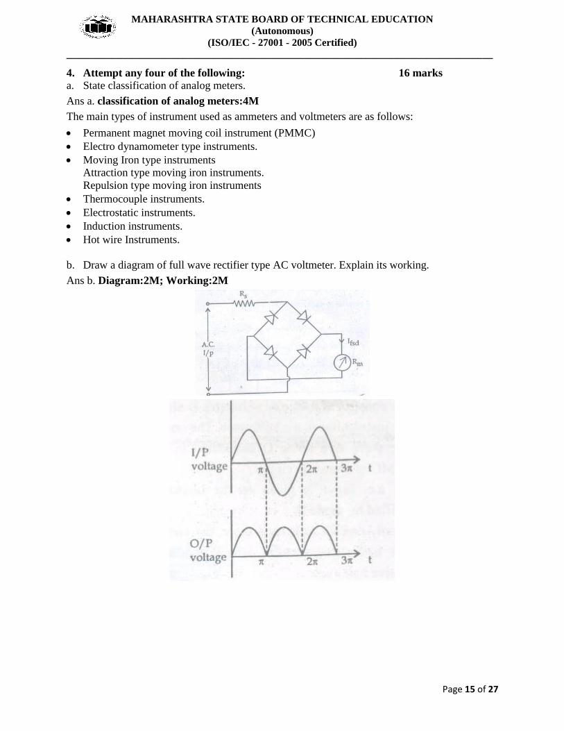
b. Draw a diagram of full wave rectifier type AC voltmeter. Explain its working.
Ans b. Diagram:2M; Working:2M

MAHARASHTRA STATE BOARD OF TECHNICAL EDUCATION
(Autonomous)
(ISO/IEC - 27001 - 2005 Certified)
____________________________________________________________________________________
Page 16 of 27

MAHARASHTRA STATE BOARD OF TECHNICAL EDUCATION
(Autonomous)
(ISO/IEC - 27001 - 2005 Certified)
____________________________________________________________________________________
Page 17 of 27
c. Derive the relation between deflection torque in PMMC instruments.
Ans c.
Deflecting Torque Equation:
Torques which deflect the pointer from its zero position is known as deflecting torque.
The deflecting of pointer is directly proportional to quantity to be measured.
The deflection torque produced due to current flowing through coil.
Let length of coil be L meter and width of coil be d meter. Assume, I is the current flowing
through coil having N turn. B is consider as flux density produce in air gap.
Therefore the force exerted by coil is
F= BiL
The deflecting torque is given by
Td = Force x distance
Td = F x S
= B x l x I x N x d ----------------- (1)
Td = B x A x I x N ----------------- (2)
Where, A = l x d = Area of coil former.
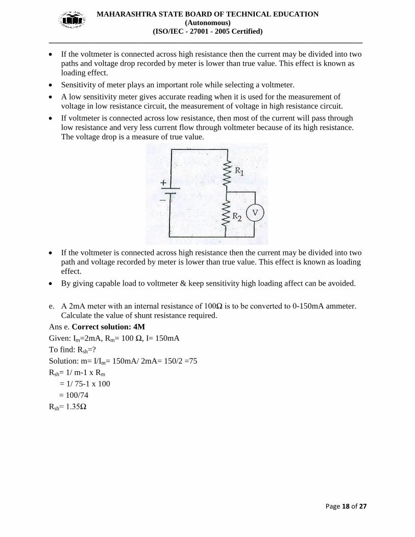
d. Explain the loading effect in voltmeters. How to avoid it?
Ans d. Loading effect in voltmeters:2M. How to avoid it:2M
Sensitivity of meter plays an important role while selecting a voltmeter.
A low sensitivity meter gives accurate reading when it is used for the measurement of
voltage in low resistance circuit, but it may give inaccurate reading during the measurement
of voltage in high resistance circuit.
If voltmeter is connected across low resistance, then most of the current will pass through
low resistance and very less current flow through voltmeter because of its high resistance.
The voltage drop is a measure of true value.
MAHARASHTRA STATE BOARD OF TECHNICAL EDUCATION
(Autonomous)
(ISO/IEC - 27001 - 2005 Certified)
____________________________________________________________________________________
Page 18 of 27
If the voltmeter is connected across high resistance then the current may be divided into two
paths and voltage drop recorded by meter is lower than true value. This effect is known as
loading effect.
Sensitivity of meter plays an important role while selecting a voltmeter.
A low sensitivity meter gives accurate reading when it is used for the measurement of
voltage in low resistance circuit, the measurement of voltage in high resistance circuit.
If voltmeter is connected across low resistance, then most of the current will pass through
low resistance and very less current flow through voltmeter because of its high resistance.
The voltage drop is a measure of true value.
If the voltmeter is connected across high resistance then the current may be divided into two
path and voltage recorded by meter is lower than true value. This effect is known as loading
effect.
By giving capable load to voltmeter & keep sensitivity high loading affect can be avoided.
e. A 2mA meter with an internal resistance of 100Ω is to be converted to 0-150mA ammeter.
Calculate the value of shunt resistance required.
Ans e. Correct solution: 4M
Given: Im=2mA, Rm= 100 Ω, I= 150mA
To find: Rsh=?
Solution: m= I/Im= 150mA/ 2mA= 150/2 =75
Rsh= 1/ m-1 x Rm
= 1/ 75-1 x 100
= 100/74
Rsh= 1.35Ω

MAHARASHTRA STATE BOARD OF TECHNICAL EDUCATION
(Autonomous)
(ISO/IEC - 27001 - 2005 Certified)
____________________________________________________________________________________
Page 19 of 27
f. Draw a circuit diagram of Aytron shunt type ammeter. What is the advantage of it over
normal shunt type ammeter?
Ans f. Circuit diagram:2M; Advantage:2M
Sensitivity is high as compared to normal shunt type ammeter
5. Attempt any FOUR of the following: 16 marks
a. State any four applications of CRO.
Ans a. Any four applications:4M
1. It is used in laboratory for measurement of AC/DC voltage, current, frequency, phase and
study nature of waveform.
2. It is used in TV receiver for creation of images.
3. It is used in radar receiver for giving visual indication of target such as aeroplane, ship etc.
4. It is used to test AF circuit for different distortion.
5. It is used to check faulty component.
6. It is used to check signals at radio and TV receiver.
7. It is used to check B-H curve of different ferromagnetic material.
8. It is used in medical equipment such as ECG, patient monitor.
9. It is used to check modulation percentage of modulated wave.
10. It is also used to check radiation pattern generated by antenna.

MAHARASHTRA STATE BOARD OF TECHNICAL EDUCATION
(Autonomous)
(ISO/IEC - 27001 - 2005 Certified)
____________________________________________________________________________________
Page 20 of 27
b. Draw a basic block diagram of digital storage CRO. Write the function of each block.
Ans b. (diagram – 2 marks, explanation – 2 marks)
Block Diagram:
Fig. Block diagram of Digital Storage Oscilloscope
The analog voltage input signal is digitized in a 10 bit A/D converter with a resolution of
0.1% (1 part in 1024) and frequency response of 25 kHz. The total digital memory storage
capacity is 4096 for a single channel, 2048 for two channels each and 1024 for four channels
each.
The analog input voltage is sampled at adjustable rates (Upto 100, 000 samples per second)
and data points are read onto the memory. A maximum of 4096 points are storable in this
particular instrument. (Sampling rate and memory size are selected to suit the duration and
waveform of the physical event being recorded.)
Once the sample record of the vent is captured in memory, many useful manipulations are
possible, since memory can be read out without being erased.
If the memory is read out rapidly and repetitively, an input event which was a single shot
transient becomes a repetitive or continuous waveform that can be observed easily on an
ordinary scope(without going through DAC) to say a computer where a stored program can
manipulate the data in almost anyway desired.
MAHARASHTRA STATE BOARD OF TECHNICAL EDUCATION
(Autonomous)
(ISO/IEC - 27001 - 2005 Certified)
____________________________________________________________________________________
Page 21 of 27
Pre triggering recording allows the input signal preceding the trigger points to be recorded. In
ordinary triggering the recording process is started by the rise of the input (or some external
triggering) above some preset threshold value.
As in digital recorder, DSO can be set to record continuously(new data coming into the
memory pushes out the old data, once memory is full), until the trigger signal is received;
then the recording is stopped, thus freezing data received prior to the trigger signal in the
memory.
An adjustable trigger delay allows operator control of the stop point, so that the trigger may
occur near the beginning, middle or end of the stored information.
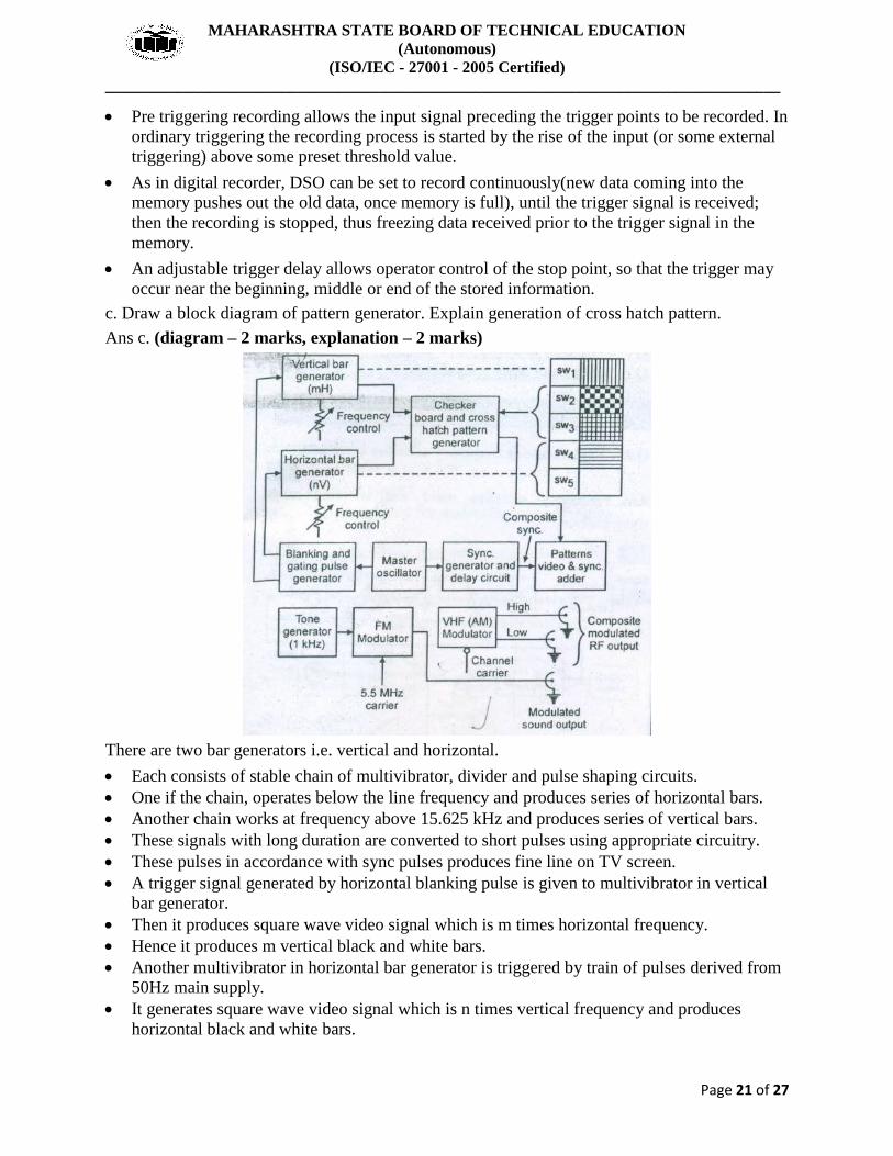
c. Draw a block diagram of pattern generator. Explain generation of cross hatch pattern.
Ans c. (diagram – 2 marks, explanation – 2 marks)
There are two bar generators i.e. vertical and horizontal.
Each consists of stable chain of multivibrator, divider and pulse shaping circuits.
One if the chain, operates below the line frequency and produces series of horizontal bars.
Another chain works at frequency above 15.625 kHz and produces series of vertical bars.
These signals with long duration are converted to short pulses using appropriate circuitry.
These pulses in accordance with sync pulses produces fine line on TV screen.
A trigger signal generated by horizontal blanking pulse is given to multivibrator in vertical
bar generator.
Then it produces square wave video signal which is m times horizontal frequency.
Hence it produces m vertical black and white bars.
Another multivibrator in horizontal bar generator is triggered by train of pulses derived from
50Hz main supply.
It generates square wave video signal which is n times vertical frequency and produces
horizontal black and white bars.

MAHARASHTRA STATE BOARD OF TECHNICAL EDUCATION
(Autonomous)
(ISO/IEC - 27001 - 2005 Certified)
____________________________________________________________________________________
Page 22 of 27
The switches provided in between signal path of both multivibrator produces different
patterns.
If both mH and nV switch are OFF a blank white raster is produced.
When only mH switch is ON, vertical bars are produced.
When only nV switch is ON, horizontal bars are produced.
When both mH & nV is ON, cross hatch pattern is generated.
d. Draw the block diagram of Logic analyzer. List the types or modes of displays in it.
Ans d. (diagram – 2 marks, types – 2 marks)
The types or modes of display in logic analyzers are of two types:
1. Logic Timing
2. Logic state
e. Draw a block diagram of wave analyzer. Write its principle.
Ans e. (diagram – 2 marks, principle – 2 marks)

MAHARASHTRA STATE BOARD OF TECHNICAL EDUCATION
(Autonomous)
(ISO/IEC - 27001 - 2005 Certified)
____________________________________________________________________________________
Page 23 of 27
OR
A wave analyzer consists of a primary detector, which is a simple LC circuit. This LC circuit is
adjusted for resonance at the frequency of the particular harmonic component to be measured.
The intermediate stage is a full-wave rectifier to obtain the average value of input signal. The
indicating device is a simple DC voltmeter that is calibrated to read the peak value of the
sinusoidal input voltage. Since the LC circuit is tuned to a single frequency, it passes only the
frequency to which it is tuned and rejects all other frequencies. A number of tuned filters,
connected to the indicating device through a selector switch would be required for a useful wave
analyzer.
f. Describe the operation of spectrum analyzer with neat diagram.
Ans f. (diagram – 2 marks, operation – 2 marks)
Spectrum analyzer consists of voltage tune oscillator, mixer, IF amplifier, detector, video
amplifier, sweep generator and CRT.
The input signal applied to the circuit is used with oscillator signal, produces two different
frequencies called intermediate frequency.
The voltage control oscillator (VCO) swept (toggle) between minimum and maximum frequency
linearly. The sawtooth waveform plays important role in controlling the output voltage control
oscillator.
MAHARASHTRA STATE BOARD OF TECHNICAL EDUCATION
(Autonomous)
(ISO/IEC - 27001 - 2005 Certified)
____________________________________________________________________________________
Page 24 of 27
The IF signal is then amplified by IF amplifier for further processing.
The information in signal is detected by detector and further amplified by video
amplifiers. Then these signals are fed to the vertical deflecting plate of CRT.
The sawtooth waveform also supply signal to horizontal deflecting plates after the amplification.
The CRT produces amplitude versus frequency waveform on the screen.
In this type the signal are broken down into their individual frequency component
6. Attempt any four of the following: 16 marks
a. Compare analog and digital meters (any 4points)
Ans a. (any four correct points – 1 mark each)
Sr.No Functions Analog Multimeter Digital
1 Display Analog pointer is used LCD display is used.
2 Resolution Low resolution High resolution
3 Functions available Current, resistance, voltage
measurement possible
Current, voltage, resistance,
hfe measurement possible
4 Power consumption More power required Less power required.
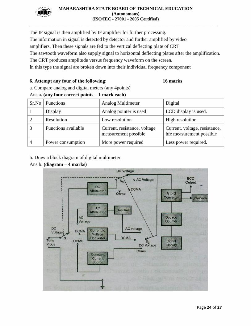
b. Draw a block diagram of digital multimeter.
Ans b. (diagram – 4 marks)

MAHARASHTRA STATE BOARD OF TECHNICAL EDUCATION
(Autonomous)
(ISO/IEC - 27001 - 2005 Certified)
____________________________________________________________________________________
Page 25 of 27
c. What do you mean by 3 ½ digit display?
Ans c. (correct explanation – 4 marks)
The number of digit positions used in a digital meter determines the resolution. Hence a 3 digit
display on DVM for a 0-1 range will indicate values from 0-999 mV with a smallest increment
of 1mV.
Normally a fourth digit capable of indicating 0 or 1 (hence called a half digit) is placed to the
left. This permits the digital meter to read values above 999 up to 1999, to give overlap between
ranges for convenience, a process called over ranging. This type of display is called a 3 ½digit
display.
d. Draw a block diagram of digital frequency meter. Explain its operation.
Ans d. (diagram – 2 marks, explanation – 2 marks)
Frequency is defined as number of cycles per unit time interval. The signal whose frequency
is to be measured is used as an event.
The unknown frequency is first converted to train of pulses. One pulse represents one cycle
of unknown signal. These pulses are directly proportional to the frequency to be measured.
The signal whose frequency is to be measured is first amplified. The output of amplifier is
applied to the Schmitt trigger.
The Schmitt trigger converts the signal into square wave having fast rise and fall times.
The square wave is then differentiated and clipped. Each pulse is proportional to each cycle
of unknown signal.
The output from Schmitt trigger is applied to start and stop gate. These pulses are applied to
the switch.
This switch is controlled by a signal having definite time interval. The main gate switch is
closed for known time interval.
When the gate is open, input pulses are allowed to pass through it. A counter will now start
to count these pulses.
When the gate is closed, input pulses are not allowed to pass through the gate. The counter
will now stop counting.
The number of pulses during the period gate is open are counted by the counter.
If this interval between start and stop condition is known, the frequency of unknown signal
is measured.
F= N/t
Where,
F= Unknown frequency

MAHARASHTRA STATE BOARD OF TECHNICAL EDUCATION
(Autonomous)
(ISO/IEC - 27001 - 2005 Certified)
____________________________________________________________________________________
Page 26 of 27
N= Number of counts displayed by the counter.
t= Time interval between start and stop condition of the gate.
e. Explain SAR type digital voltmeter with neat labelled diagram.
Ans e. (diagram – 2 marks, explanation – 2 marks)
Successive approximation DVMs are capable of 1000 readings per second.
these instruments make use of successive approximation converter for analog to digital
conversion. A simplified block diagram of such a DVM.
In the beginning of measurement cycle, a start pulse is applied to the (start/ stop)
multivibrator. This sets a MSB of control register high and all other bits low.
Assuming a 8 bit control register, its reading would then be 10000000. This initial setting of
control register causes the output of DAC to be one half the reference supply (1/2V).
The converter output is compared with unknown input by the comparator.
It produces an output which causes the control register to retain 1 at its MSB and converter
register to retain 1 at its MSB and converter continues to supply its reference voltage of ½ V.
The ring counter next advances one count, shifting a 1 in the second digit. MSB of the
control register and its reading becomes 11000000.
This makes D/A converter to increase its reference by one increment to 1/2V +1/4 V and
another comparison with unknown input voltage takes place.
If accumulates reference exceeds the unknown voltage the comparator produces and output
that causes the control register to reset its MBS to 0.
Finally when the ring counter reaches its last count, the measurement cycle stops and the
digital output of control register represents the final approximation of the unknown input
voltage.

MAHARASHTRA STATE BOARD OF TECHNICAL EDUCATION
(Autonomous)
(ISO/IEC - 27001 - 2005 Certified)
____________________________________________________________________________________
Page 27 of 27
f. Write any four specifications of DMM.
Ans f. (any four correct specifications – 1 mark each)
Specifications of DMM are as follows:
1. D.C. Voltage:
2. AC Voltage:
3. Resistance:
Ω
4. D.C. Current:
5. A.C. Current: