summer 15 examinations subject code: 17455 model...
TRANSCRIPT
MAHARASHTRA STATE BOARD OF TECHNICAL EDUCATION (Autonomous)
(ISO/IEC - 27001 - 2005 Certified)
Page 1 of 33
SUMMER – 15 EXAMINATIONS Subject Code: 17455 Model Answer Important Instructions to examiners: 1) The answers should be examined by key words and not as word-to-word as given in the model answer scheme. 2) The model answer and the answer written by candidate may vary but the examiner may try to assess the understanding level of the candidate. 3) The language errors such as grammatical, spelling errors should not be given more importance. (Not applicable for subject English and Communication Skills) 4) While assessing figures, examiner may give credit for principal components indicated in the figure. The figures drawn by candidate and model answer may vary. The examiner may give credit for any equivalent figure drawn. 5) Credits may be given step wise for numerical problems. In some cases, the assumed constant values may vary and there may be some difference in the candidate’s answers and model answer. 6) In case of some questions credit may be given by judgment on part of examiner of relevant answer based on candidate’s understanding. 7) For programming language papers, credit may be given to any other program based on equivalent concept.

MAHARASHTRA STATE BOARD OF TECHNICAL EDUCATION (Autonomous)
(ISO/IEC - 27001 - 2005 Certified)
Page 2 of 33
Q. NO.
MODEL ANSWER
MARKs
TOTAL
1. Attempt any five
5 X 4 20
a)
A, Butt weld.
B, Single vee.
C, Double vee (heavy plates.)
D, U-shaped (heavy casting).
E, Flange weld (thin metal).
F, Single strap butt joint
G, Lap joint (single- or double-fillet weld).
H, Joggled lap joint (single or double weld,
I, Tee joint (fillet welds).
J, Edge weld (used on thin plates).
K, Corners weld metal).
L, Plug or rivet butt joint
2m for naming 2m for sketch
4m
MAHARASHTRA STATE BOARD OF TECHNICAL EDUCATION (Autonomous)
(ISO/IEC - 27001 - 2005 Certified)
Page 3 of 33
b)
Electric Arc Welding:- Arc welding is a type of welding that uses a welding power supply to create an electric arc between an electrode and the base material to melt the metals at the welding point. They can use either direct (DC) or alternating (AC) current, and consumable or non-consumable electrodes. The welding region is usually protected by some type of shielding gas, vapor, or slag. An electric arc length, or arc discharge, is an electrical breakdown of a gas that produces an ongoing plasma discharge, resulting from a current through normally nonconductive media such as air. An arc discharge is characterized by a lower voltage than a glow discharge, and relies on thermionic emission of electrons from the electrodes supporting the arc
2m For def. 2m for charac.
4m
c) Factors that effect the arc penetration are:
Polarity
Welding process
Type of electrode used
Shielding gas type
Electrode diameter
Travel speed
Current used
1m for each
4m
d) Welding Techniques - Depending upon the ways in which welding rod and the welding torch may be used, there are two usual techniques in gas welding, namely: 1. Leftward technique or Forehand welding method. 2. Rightward technique or Back hand welding method
2m for each technique
4m
e)
Weldability is the capacity of a material to be welded under the fabrication conditions imposed into a specific suitably designed structure and to perform satisfactorily in the intended service. Factors effecting are: •Composition of the metal •Brittleness and strength of metal at elevated temperature •Thermal properties of metal •Welding techniques,fluxing material and filler material •Proper heat treatment before and after the deposition of the metal.
2m For def 2m for Factors
4m

MAHARASHTRA STATE BOARD OF TECHNICAL EDUCATION (Autonomous)
(ISO/IEC - 27001 - 2005 Certified)
Page 4 of 33
f) Heat treatment involves the use of heating or chilling, normally to extreme temperatures, to achieve a desired result such as hardening or softening of a material. Stresses introduced in structures due to welding sometimes rise to values as high as the yield strength of the material, and when combined with the stresses from external service loads, it is very possible that resulting (stress) values may exceed design stresses. The effect of these is: (a) to increase susceptibility to brittle fracture, (b) to increase susceptibility to stress-corrosion cracking, (c) to reduce dimensional stability. - Likewise, these residual stresses are known to cause distortion of the structure, particularly if it is to be machined. Removal of some surface metal may cause the redistribution of these induced stresses. As a consequence, some parts go out of shape, making it impossible to obtain desired alignment. All this stresses the need to minimize residual welding stresses particularly (a) when weldments are subjected to dynamic loads, (b) in the case of important welded products.
2m for def 2m for uses
4m
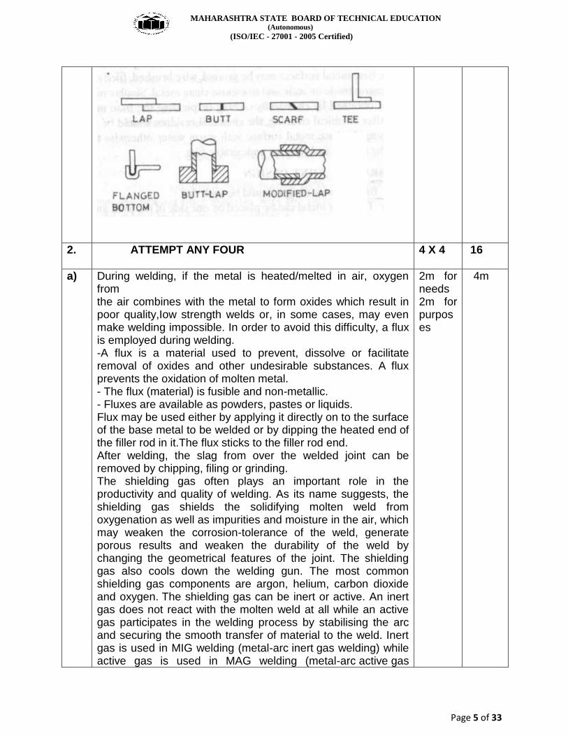
g) BRAZING JOINT DESIGN Brazing joint design should be such that: (i) The filler metal can be placed on one side of the joint and pulled through the joint by capillary action. (ii) There is an allowance for preplacernent or feeding of the filler metal into the joint area. (iii) The joint meets service requirements, e.g. Mechanical performance Electrical and Thermal conductivity Pressure tightness Corrosion resistance Good appearance Service temperature. - The type of joints used for brazing include the lap, scarf butt joint, square butt joint, tee joint, The lap joint probably gives the most satisfactory results in terms of optimum strength requirements. The length of the lap should be equal to at least three times the thickness of the thinnest member of the joint.
4m 4m
MAHARASHTRA STATE BOARD OF TECHNICAL EDUCATION (Autonomous)
(ISO/IEC - 27001 - 2005 Certified)
Page 5 of 33
2. ATTEMPT ANY FOUR 4 X 4 16
a)
During welding, if the metal is heated/melted in air, oxygen from the air combines with the metal to form oxides which result in poor quality,Iow strength welds or, in some cases, may even make welding impossible. In order to avoid this difficulty, a flux is employed during welding. -A flux is a material used to prevent, dissolve or facilitate removal of oxides and other undesirable substances. A flux prevents the oxidation of molten metal. - The flux (material) is fusible and non-metallic. - Fluxes are available as powders, pastes or liquids. Flux may be used either by applying it directly on to the surface of the base metal to be welded or by dipping the heated end of the filler rod in it.The flux sticks to the filler rod end. After welding, the slag from over the welded joint can be removed by chipping, filing or grinding. The shielding gas often plays an important role in the productivity and quality of welding. As its name suggests, the shielding gas shields the solidifying molten weld from oxygenation as well as impurities and moisture in the air, which may weaken the corrosion-tolerance of the weld, generate porous results and weaken the durability of the weld by changing the geometrical features of the joint. The shielding gas also cools down the welding gun. The most common shielding gas components are argon, helium, carbon dioxide and oxygen. The shielding gas can be inert or active. An inert gas does not react with the molten weld at all while an active gas participates in the welding process by stabilising the arc and securing the smooth transfer of material to the weld. Inert gas is used in MIG welding (metal-arc inert gas welding) while active gas is used in MAG welding (metal-arc active gas
2m for needs 2m for purposes
4m

MAHARASHTRA STATE BOARD OF TECHNICAL EDUCATION (Autonomous)
(ISO/IEC - 27001 - 2005 Certified)
Page 6 of 33
welding)
b)
Flat
In a flat position, a weld is performed along largely a horizontal
access and from above the joint. It is the easiest type of weld
to perform. In this position, the welding is performed from the
upper side of the joint, and the face of the weld is
approximately horizontal.
Horizontal
In the horizontal position, the weld’s axis is the horizontal
plane. Horizontal welding is often used for fillet or groove
welds. The axis of a weld is a line through the length of the
weld, perpendicular to the cross section at its center of gravity.
Vertical
With a vertical position, the weld’s axis is largely in a vertical or
upright position. It is typically more complicated to perform than
flat and horizontal welding. vertical surface. In vertical position
pipe welding, the axis of the pipe is vertical.
Overhead
1m for each position
4m

MAHARASHTRA STATE BOARD OF TECHNICAL EDUCATION (Autonomous)
(ISO/IEC - 27001 - 2005 Certified)
Page 7 of 33
In this the most complicated of the four, welding is performed
from the underside of the joint. In this welding position, the
welding is performed from the underside of a joint.
c) WELDING OF MILD STEEL. - Mild steels be welded using the following processes: (a) Flux Shielded Metal Arc Welding. (b) Oxy-acetylene Welding. (c) Resistance Welding. (d) Thermit Welding. (e) Submerged Arc Welding. (a) When using flux shielded Metal Arc Welding (i) Low hydrogen electrodes may be employed to reduce weld cracking.. (ii) Preheating temperatures between 150 to 260 0C are recommended to eliminate and reduce the hard and brittle areas. , The heavier the section thickness and the greater the carbon content of steel, the higher would be the preheating temperatures. ' (iii) After welding, the job should be allowed to cool to room temperature slowly by being buried in sand or asbestos. (iv) Post-heating the job (after welding) between 595 and 675°C for one hour per 25 mm of section thickness. Improves the metallurgical structure Increases the ductility Reduces residual welding stresses. (b) When employing Oxy-acetylene Welding - (i) An excess of acetylene is used in the gas flame. (ii) No flux is used. (iii) An alloy steel or high tensile steel welding rod may be used. (iv) Little problem is created by the formation of hard and brittle constituents as a result of cooling. (v) Welding is carried out similar to that for low carbon steels. (vi) Post heat-treatment improves quality of the welded joint. (c) When employing Resistance Welding Special provisions are made in the welding cycle for preheating and post heating. These provisions retard the cooling rate while the weld is under pressure and result in greater ductility and strength in the completed weld.
4m 4m
MAHARASHTRA STATE BOARD OF TECHNICAL EDUCATION (Autonomous)
(ISO/IEC - 27001 - 2005 Certified)
Page 8 of 33
(d) Thermits Welding is done generally using forging thermit. The increase in carbon from the base metal produces a weld of higher tensile strength but lower ductility as compared to a weld made with low carbon steel as the base metal. (e) Submerged Arc Welding (i)Uses welding rods and fluxes same as those used for low carbon steels. (ii) Employs preheating of thick sections to reduce hardness of heat affect zone.
d) Effect of welding on properties of metal - Welding involves many metallurgical phenomena. Welding operation somewhat resembles to casting. - In all welding processes, except cold welding, heating and cooling are essential and integral parts of the process. High degrees of superheat in the weld metal may be obtained in many fusion welding processes. Heat affected zone 1. The grain growth region 2. The grain refined region, . 3. The transition region The grain growth region. - Grain growth region is immediately adjacent to the weld metal zone (fusion boundary). - In this zone parent metal has been heated to a temperature well above the upper critical (A3) temperature. This resulted in grain growth or coarsening of the structure. (b) The grain refined region - Adjacent to the grain growth region is the grain refined zone. - The refined zone indicates that in this region, the parent metal has been heated to just above the A 3 temperature where grain refinement is completed and the finest grain structure exists. (c) The Transition zone In the transition zone. a temperature range exists between the lower critical temperature and upper critical temperature transformation temperatures where partial allotropic recrystallization takes place (c) Unaffected Parent Metal - Outside the heat affected zone is the parent metal that was not heated sufficiently to change its microstructure. OR
4m(1m for each point)
4m
MAHARASHTRA STATE BOARD OF TECHNICAL EDUCATION (Autonomous)
(ISO/IEC - 27001 - 2005 Certified)
Page 9 of 33
Effects of various elements on welding rods is listed below. Carbon During solidification grain growth occurs, resulting to increase in, hardness and residual stresses. The metal shows cracks and brittleness. dutility is poor. Manganese The presence of 1.1% manganese raises the yield point and ultimate tensile strength of the weld to the maxi mum limit. Excessive manganese along with the carbon content increases hardness, hardenability and tendency to cracks. Silicon Silicon is a strong deoxidiser but excess amount acts as impurity in steels. Sulphur Sulphur readily combines with iron'and forms iron sulphide (FeS). It has low melting point and reduces adhesiveness between adjacent grains of the metal. Phosphorus Phosphorus forms iron phosphides steel. It decreases the plasticity of the metal. In cast iron welding phosphorus content from 0.5 to 1.0% is desirable. It increase fluidity of the molten metal and helps the filling grooves properly. Nickel The properties of nickel are similar to maganese.It increases strength, hardness, hardenability.. toughness and ductility of steel. Chromium Chromium forms complex carbides increases the hardness without decreasing the toughness when added in quantities up to 1.5 Vanadium It's a strong oxidizer When used as an alloy it strengthens the weldability and increases hardenability Tungsten Tungsten reacts with iron and forms complex carbides. It affects the properties of steel even in small quantities by increasing harnessand strength. Molybdenum The properties of molybdenum are similar to tungsten and act a cheaper substitute of tungsten.
e) SoIdering is defined as a group of ioining processes wherein coalescence is produced by heating to a suitable temperature and by using a filler metal having a liquidus not exceeding 800°F(427°C)and below the solidus of the base metal.The filler metal (i.e., the solder) is usually distributed between:ure properly fitted surfaces of the joint by capillary attraction. Soldering:- It is a group of joining processes in which joint is produced by heating to a suitable temperature & by using a filler metal having a liquidus not exceeding 427 C & below the solidus of the base metal. Applications: Soldering is used in plumbing, electronics, and metalwork from flashing to jewelry.
2m for def 1/2m for each adv 1/2m for each app.(any four)
4m

MAHARASHTRA STATE BOARD OF TECHNICAL EDUCATION (Autonomous)
(ISO/IEC - 27001 - 2005 Certified)
Page 10 of 33
Soldering provides reasonably permanent but reversible connections between copper pipes in plumbing systems as well as joints in sheet metal objects such as food cans, roof flashing, rain gutters and automobile radiators.Jewelry components, machine tools and some refrigeration and plumbing components are often assembled and repaired by the higher temperature silver soldering process. Small mechanical parts are often soldered or brazed as well. Soldering is also used to join lead came and copper foil in stained glass work. It can also be used as a semi-permanent patch for a leak in a container or cooking vessel. Electronic soldering connects electrical wiring and electronic components to printed circuit boards (PCBs) Advantages of soldering Low power is required; Low process temperature; No thermal distortions and residual stresses in the joint parts; Microstructure is not affected by heat; Easily automated process; Dissimilar materials may be joined; High variety of materials may be joined; Thin wall parts may be joined; Moderate skill of the operator is required.
f) TYPES OF METAL TRANSFER There are two main types of metal transfer: (a) Free Flight Transfer. In which metal drops get detached from the electrode, pass through the arc and fall on the job. This category of metal transfer can further be classified as follows:
(i) Sub-threshold type. The drop diameter is approximately equal to three times the electrode core wire diameter. (ii) Globular type.
1m for state 2m for exp. 1m for sketch
4m
MAHARASHTRA STATE BOARD OF TECHNICAL EDUCATION (Autonomous)
(ISO/IEC - 27001 - 2005 Certified)
Page 11 of 33
The drop diameter is approximately twice the electrode core wire diameter. This type of transfer is observed in both flux shielded metal arc welding and MIG welding processes. Globular transfer is observed at low arc currents or with longer arcs. The globules may pass freely through the welding arc or depending upon their size and arc gap they may short-circuit the arc. The number of drops transferred per second are very less. Globular transfer is associated with spatter loss and shallow penetration height. (iii) Spray type. In this case the drop diameter is approximately equal to electrode core wire diameter. The rate of drop transfer is much higher than that in globular transfer. There is a continuous spray of drops from the electrode to the job. This type of transfer occurs at high arc currents and low arc lengths. Spray transfer is observed in both flux-shielded metal arc welding and MIG welding. A mixture of argon and oxygen promotes spray transfer in MIG welding. Though associated with some spatter, spray mode of transfer produces a stable are, good weld bead, deep penetration, a strong joint and is recommended for thicker plates. (iv) Jet type. In jet type of transfer the drop diameter is approximately equal to half the diameter of the wire. In this case the electrode end becomes tapered and a jet of drops comes out from the electrode .The temperature of the droplet formed from a steel electrode just as it detaches, ranges from 1800-2000 0C.The size of a droplet ranges between 0.5 to 5 mm. The velocity at which drop transfer takes place depends upon drop size. (b) Short-circuiting or Dip Transfer
MAHARASHTRA STATE BOARD OF TECHNICAL EDUCATION (Autonomous)
(ISO/IEC - 27001 - 2005 Certified)
Page 12 of 33
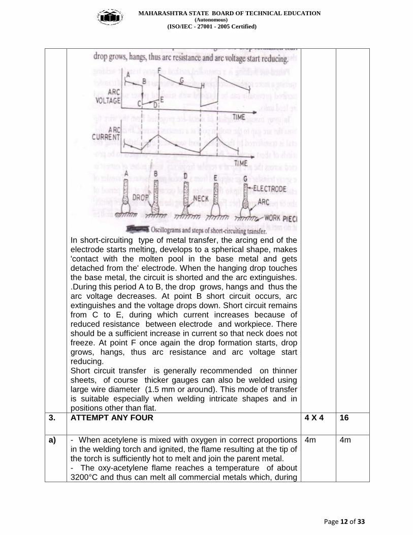
In short-circuiting type of metal transfer, the arcing end of the electrode starts melting, develops to a spherical shape, makes 'contact with the molten pool in the base metal and gets detached from the' electrode. When the hanging drop touches the base metal, the circuit is shorted and the arc extinguishes. .During this period A to B, the drop grows, hangs and thus the arc voltage decreases. At point B short circuit occurs, arc extinguishes and the voltage drops down. Short circuit remains from C to E, during which current increases because of reduced resistance between electrode and workpiece. There should be a sufficient increase in current so that neck does not freeze. At point F once again the drop formation starts, drop grows, hangs, thus arc resistance and arc voltage start reducing. Short circuit transfer is generally recommended on thinner sheets, of course thicker gauges can also be welded using large wire diameter (1.5 mm or around). This mode of transfer is suitable especially when welding intricate shapes and in positions other than flat.
3. ATTEMPT ANY FOUR 4 X 4 16
a)
- When acetylene is mixed with oxygen in correct proportions in the welding torch and ignited, the flame resulting at the tip of the torch is sufficiently hot to melt and join the parent metal. - The oxy-acetylene flame reaches a temperature of about 3200°C and thus can melt all commercial metals which, during
4m 4m
MAHARASHTRA STATE BOARD OF TECHNICAL EDUCATION (Autonomous)
(ISO/IEC - 27001 - 2005 Certified)
Page 13 of 33
welding, actually flow together to form a complete bond. A ruler metal rod is generally added to the molten metal pool to build up the seam slightly for greater strength - Oxy-acetylene welding does not require the components to be forced together under pressure until the weld forms and solidifies Welder has considerable control over the temperature of the metal in the weld zone. When the rate of heat input from the flame is properly coordinated with the speed of welding, the size, viscosity and surface tension of the weld puddle can be controlled, permitting the pressure of the flame to be used to aid in positioning and shaping the weld.
b)
MANUFACTURE OF ELECTRODES Wires of different chemical compositions and sizes are obtained from different steel manufacturers. In electrode making plant, they are chemically cleaned, cut to different lengths (300, 350, 450 mm etc.) and straightened. There are two methods of applying flux coating on the core wire, (a) by dipping, (b) by extrusion. Extrusion method is very fast and economical; produces strong uniform and concentric coatings and has largely replaced the dipping process. CARE AND STORAGE OF ELECTRODES Utmost care is required in handling and storage of electrodes. Electrodes coating should neither get damped nor be damaged or broken. 1. Electrodes with damp coating will produce a violent arc, porosity and cracks in the joint.Electrodes with damaged coating will produce joints of poor mechanical properties. 2. To avoid damage to coating, (a) electrodes during storage should neither bend nor deflect, (b) electrode packets should not be thrown or piled over each other. 3. Electrodes should be stored in dry and well-ventilated store rooms.Storage temperature should be about 12°C above that of external air temperature with 0--60% humidity. Cellulose electrodes are not so critical but they should be protected against condensation and stored in a humidity of 0-90%. 4. Before use the electrodes may be dried as per manufacturer's recommendations 5. All electrodes, and especially costlier ones, should be used till they are left hardly 40-50mm. Specified as
E XX XX or E 60 1 2
1m for spec 1 ½ m for mfg 1 ½ m for storage
4m

MAHARASHTRA STATE BOARD OF TECHNICAL EDUCATION (Autonomous)
(ISO/IEC - 27001 - 2005 Certified)
Page 14 of 33
E XXX XX or E 100 1 5 Example E 60 1 2 or Example: E317M E145P or Example:E307411
c) FOLLOWING ARE THE DEFECTS:- 1. CRACKS 2. INCOMLETE PENETRATION 3. DISTORION INCLUSIONS 4. POOR FUSION 5. POROSITY 6. POOR WELD BEAD APPEARANCE 7. UNDERCUTTING 8. SPATTER 9. OVERLAPPING 10. BLOW HOLES
Inclusions
There are two types of inclusions: linear inclusions and rounded inclusions. Inclusions can be either isolated or cumulative. Linear inclusions occur when there is slag or flux in the weld. Slag forms from the use of a flux, which is why this type of defect usually occurs in welding processes that use flux, such as shielded metal arc welding, flux-cored arc welding, and submerged arc welding, but it can also occur in gas metal arc welding.
This defect usually occurs in welds that require multiple passes and there is poor overlap between the welds.
The poor overlap does not allow the slag from the previous weld to melt out and rise to the top of the new weld bead.
It can also occur if the previous weld left an undercut or an uneven surface profile.
To prevent slag inclusions the slag should be cleaned from the weld bead between passes via grinding, wire brushing, or chipping.
Undercut
Undercutting is when the weld reduces the cross-sectional
1m each defect
4m

MAHARASHTRA STATE BOARD OF TECHNICAL EDUCATION (Autonomous)
(ISO/IEC - 27001 - 2005 Certified)
Page 15 of 33
thickness of the base metal, which reduces the strength of the weld and work pieces.
One reason for this type of defect is excessive current, causing the edges of the joint to melt and drain into the weld; this leaves a drain-like impression along the length of the weld. Another reason is if a poor technique is used that does not deposit enough filler metal along the edges of the weld.
A third reason is using an incorrect filler metal, because it will create greater temperature gradients between the center of the weld and the edges.
Other causes include too small of an electrode angle, a dampened electrode, excessive arc length, and slow speed.
Cracks
Cracks are the most dangerous amongst all types of defects as it reduce the performance of a welded joint drastically and can also cause catastrophic failure. Depending on the position, location and orientation these can be categorized as longitudinal cracks, transverse cracks, crater cracks, under-bead cracks, and toe cracks.
d) Brazing is a metal-joining process whereby a filler metal is heated above melting point and distributed between two or more close-fitting parts by capillary action. The filler metal is brought slightly above its melting (liquidus) temperature while protected by a suitable atmosphere, usually a flux. Advantages:- Since brazing does not melt the base metal of the joint, it allows much tighter control over tolerances and produces a clean joint without the need for secondary finishing. Additionally, dissimilar metals and non-metals (i.e. metalized ceramics) can be brazed In general, brazing also produces less thermal distortion than welding due to the uniform heating of a brazed piece. Complex and multi-part assemblies can be brazed cost-effectively.
2m Def. 1m For adv. 1m for app.
4m
e) When an electric arc is struck (about 50% of) the electrical energy fed into the arc is available as heat energy. In the field of welding, electric arc is used as a heat source to melt base metal and electrode (if consumable) in order to form a strong union between the parts to be joined. Electric welding arc besides being a heat source, transfers material, creates
4m 4m

MAHARASHTRA STATE BOARD OF TECHNICAL EDUCATION (Autonomous)
(ISO/IEC - 27001 - 2005 Certified)
Page 16 of 33
turbulence in the molten weld pool, influences slag-gas metal reactions, weld bead geometry, weld metal structures and thus in turn the mechanical properties of the welded joints. Welding arc has been defined as a sustained electrical discharge through an ionized gas. The discharge is initiated by an avalanche of electrons emitted from the hot cathode and maintained by thermal ionization of the hot gas. This electrical discharge through an ionized gas (or a high temperature conducting plasma) produces a good amount of heat energy which is employed for joining various metals and alloys by fusion. A welding arc is a high current (up to 2000 amps.) and low voltage (10-50 V) discharge. It can be considered as a flexible conductor(of a compressible fluid) carrying electrical charges in a vector motion and a plasma jet in purely kinetic motion.
4. ATTEMPT ANY FOUR
4 X 4 16
a)
FOLOWING ARE THE TYPES OF FLAMES
1) NEUTRAL FLAME:- A neutral flame is produced when approximately equal volumes of Oxygen acetylene are mixed in the welding torch & burnt at the torch tip. The temperature of the neutral flame is of the order about 5900 F. The flame has a nicely defined inner cone which is light blue in colour.It is surrounded by an outer envelope which is much darker than blue. Application:- Mild steel, Aluminium, Stainless Steel, Copper, Cast iron
2m for sketch,2m for expl.
4m
MAHARASHTRA STATE BOARD OF TECHNICAL EDUCATION (Autonomous)
(ISO/IEC - 27001 - 2005 Certified)
Page 17 of 33
2) OXIDISING FLAME:- If after the neutral flame has been established the supply of an oxidising flame can be recognised by the small white cone which is shorter , much blue in colour & more painted than that of the neutral flame.This is because of excess oxygen & which causes the temperature to rise as high as 6300 F. Applications:- Copper base metals, Zinc base metals, Manganese steel, cast iron.
3) Reducing Flame:- If the volume of oxygen supplied to the neutral flame is reduced, the resulting flame will be a carburizing flame or reducing flame which is rich in acetylene. A reducing flame has an approximate temperature of 5500 F. It can be recognized by the acetylene feather which exists in between the inner cone & the outer envelope. Applications:- Nonferrous alloys, High carbon steels, Zinc bearing alloy
b)
Arc Stability:-
Arc is said to be stable if it is uniform and steady. A stable arc will produce good weld bead and a defect-free weld nugget. Defects commonly introduced by unstable arc slag entrapment, porosity, blow holes and lack of proper fusion. The stability of a welding arc is governed by so many factors, a few, as mentioned below: . (a) Suitable matching of arc and power source characteristics. A little variation in arc length, i.e., arc voltage should not extinguish the arc. (b) Continuous and proper emission of electrons from the electrode (say cathode) and thermal iozation m the arc column. Emissivity of pure tungsten cathode is improved by making it thoriated or zirconiated. (c) Position and movements of cathode and anode spots. (d) Arc length and arc current. . (e) Electrode tip geometry in TIG welding. (g) Conditions promoting Arc Blow. (h) Presence of dampness, oil, grease etc. on the surface of workpiece. (i) Limited practice on the part of the welder. ARC BLOW The unwanted deflection or the wandering of a welding arc from its intended paths termed as arc blow or arc bow. Arc blow is the result of magnetic disturbances which unbalance the symmetry of the self-induced magnetic field around the electrode, arc and workpiece. Under arc blow, an arc may distort, deflect or rotate. Arc blow
2m Arc stability 2m Arc blow
4m
MAHARASHTRA STATE BOARD OF TECHNICAL EDUCATION (Autonomous)
(ISO/IEC - 27001 - 2005 Certified)
Page 18 of 33
becomes severe when welding is carried out in confined faces and corner on heavy metal plates. using a DC power source.AC arcs is less susceptible to arc blow than DC arcs; because the alternating current reverses direction which in turn reverses the magnetic field. The magnetic field builds up, collapses and rebuilds as current reverses from positive to negative. Its characteristics are as follows (a) magnetic fields produced in the workpiece adjacent to the welding arc, because of the current flow through the arc, (b) presence of bus bars carrying large direct currents, in the neighborhood of the place where welding is being carried out, (c) with multiple welding heads, arc at one electrode may be affected by the magnetic field of the arc at the other electrode, (d) the magnetic field produced in the workpiece around the earth connection may tend to drive the arc away from the point where this connection is made. This magnetic field is produced because of current flow from the earth connection to the workpiece.
c)
WELDING OF GRAY CAST IRON Procedure - A Vee joint with included angle of 60° to 90° may be formed (on the workpieccs to be joined) by chipping or machining. Notching or studding may be adopted to increase the strength of the weld joint - The joint is carefully cleaned of all dust, dirt, oil, grease and paint - Electrodes of cast iron, mild steel, austenitic stainless steel, nickel alloys etc., may be employed for welding gray cast iron. - The arc is struck by touching the electrode with the job. As the molten pool forms, the welding is carried out in the normal way. In order to minimize the stresses set up in the workpiece, the welds may be laid in short runs (skip welding) and then each allowed to cool. Peening the weld while hot also relieves stresses. Skip welding technique is very successful in arc welding of cast iron. A short length of weld metal is deposited in one part of the seam (Fig. ), then the next length is done some distance away, keeping the sections as far away from each other as possible thus localizing the heat. Before welding, preheating (600-700C) may be carried out and after the welding is over, the job may be covered with an insulating material to produce good quality welded joints. adv
More fluid (better castability)
3m Process 1m adv
4m
MAHARASHTRA STATE BOARD OF TECHNICAL EDUCATION (Autonomous)
(ISO/IEC - 27001 - 2005 Certified)
Page 19 of 33
Lower melting point than steel
Low cost material
Can be shaped with sand casting
Desirable Properties such as: - Damping capacity - Thermal conductivity - Ductility - Hardness - Strength
In some situations post-heat-treatment is carried out immediately after welding. In that case there is no need to cover the weld etc., with an insulating material. An AC or DC power source may be employed for welding. The current required to weld with 6 and 10 mm cast iron electrodes is approximately 300 and 400 Amps respectively.
d) 1. Crack 2. Distortion. 3. Incomplete penetration/ fusion 4. Inclusions 5. Porosity and blow holes. 6. Poor fusion 7 Spatters. 8. Undercutting. 9. Overlapping Remedies 1. CRACK: For weld Metal Cracking Preheat Relieve residual stresses mechanically Minimize shrinkage stresses using backstep or block welding sequence Change welding current and travel speed Weld with covered electrode negative; butter the joint faces prior to welding. Change to new electrode; bake electrodes to remove moisture Reduce root opening; build up the edges with weld metal Increase electrode size; raise welding current, reduce travel speed Use filler metal low in sulfur Change to balanced welding on both sides of joint Fill crater before extinguishing the arc; use a welding current decay device when terminating the weld bead. 2 DISTORTION
2m for each def.
4m
MAHARASHTRA STATE BOARD OF TECHNICAL EDUCATION (Autonomous)
(ISO/IEC - 27001 - 2005 Certified)
Page 20 of 33
Reducing the metal weld volume to avoid overfill and consider the use of intermittent welding Minimizing the number of weld runs Positioning and balancing the welds correctly round the axis Using backstep or skip welding techniques, which involves laying short welds in the opposite direction Making allowance for shrinkage by pre-setting the parts to be welded out of position Planning the welding sequence to ensure that shrinkages are counteracted progressively Shortening the welding time 3 INCOMPLETE PENETRATION/ FUSION: Remedies of incomplete fusion Follow correct welding procedure specification Maintain proper electrode position Reposition work, lower current, or increase weld travel speed Clean weld surface prior to welding 4 INCLUSIONS This defect can only be repaired by grinding down or gouging out and re-welding. 5 POROSITY AND BLOW HOLES OR GAS POCKETS Use low-hydrogen welding process; filler metals high in deoxidizers; increase shielding gas flow Use preheat or increase heat input Clean joint faces and adjacent surfaces Use specially cleaned and packaged filler wire, and store it in clean area Change welding conditions and techniques Use copper-silicon filler metal; reduce heat input Use E60I0 electrodes and manipulate the arc heat to volatilize the zinc ahead of the molten weld pool Use recommended procedures for baking and storing electrodes Preheat the base metal Use electrodes with basic slagging reactions 6 SPATTER Spatter can be minimized by correcting the welding conditions and should be eliminated by grinding when present. 7 UNDER-CUITING Undercutting can be avoided with careful attention to detail

MAHARASHTRA STATE BOARD OF TECHNICAL EDUCATION (Autonomous)
(ISO/IEC - 27001 - 2005 Certified)
Page 21 of 33
during preparation of the weld and by improving the welding process. It can be repaired in most cases by welding up the resultant groove with a smaller electrode. 8 OVERLAPPING The overlap can be repaired by grinding off excess weld metal and surface grinding smoothly to the base metal. 9 REMEDIES OF SLAG INCLUSIONS Clean surface and previous weld bead Power wire brush the previous weld bead Avoid contact between the electrode and the work; use larger electrode Increase groove angle of joint Provide proper gas shielding Reposition work to prevent loss of slag control Change electrode or flux to improve slag control Use undamaged electrodes
e)
SOLDERING JOINT DESIGN While designing a joint design the following points should be considered: (i) Service requirements. (ii) Method of heating to be employed. (iii) Fabrication method used prior to soldering. (iv) Number of components to be soldered. (v) Method of applying the solder. - A simple butt joint should be avoided as it is too weak to be
used alone. If the use of a butt joint is unavoidable, it is
advisable to use a strapped butt joint - Corner and edge joints
should also be avoided. A lap joint is very widely used; it fits
more easily and achieves.adequate strength by extending the
lap shear area. In a lap joint, the overlap may be about three
times the thickness of the thinnest member.
1m per point
4m
f) Section factors for power sources: The following factors influence the selection of a power source: 1. Available power (AC or DC, single phase, etc.). Where no power is available, a diesel engine driven DC generator may be used.
2. Available floor space. 3. Initial costs and running costs. 4. Location of operation (whether in the plant or in the field). 5. Personnel available for maintenance.
1m per point
4m

MAHARASHTRA STATE BOARD OF TECHNICAL EDUCATION (Autonomous)
(ISO/IEC - 27001 - 2005 Certified)
Page 22 of 33
6. Versatility of equipment. 7. Required output. 8. Duty cycle. 9. Efficiency. 10. Type of electrodes to be used and metals to be welded, (e.g. non-ferrous materials and stainless steels are welded more effectively with DC than with AC). 11. Type of work
5. ATTEMPT ANY FOUR
4 X 4 16
a.
ADVANTAGES OF GAS WELDING 1. It is probably the most versatile process. It can be applied to a wide variety of manufacturing and maintenance situations. 2. Welder has considerable control over the temperature of the metal in the weld zone. When the rate of heat input from the flame is properly coordinated with the speed of welding, the size, viscosity and surface tension of the weld puddle can be controlled, permitting the pressure of the flame to be used to aid in positioning and shaping the weld. 3. The rate of heating and cooling is relatively slow. In some cases, this is an advantage. 4. Since the sources of heat and of filler metal are separate, the welder has control over filler-metal deposition rates. Heat can be applied prefer entially to the base metal or the filler metal. 5. The equipment is versatile, low cost, self-sufficient and usually portable. Besides gas welding, the equipment can be used for preheating, postheating, braze welding, torch brazing and it is readily converted to oxygen cutting. 6. The cost and maintenance of the welding equipment is low when compared to that of some other welding processes. DISADVANTAGES OF GAS WELDING 1. Heavy sections cannot be joined economically. 2. Flame temperature is less than the temperature of the arc. 3. Fluxes used in certain welding and brazing' operations produce fumes that are irritating to the eyes, nose, throat and lungs. 4. Refractory metals (e.g., tungsten, molybdenum, tantalum, etc.) and reactive metals (e.g., titanium and zirconium) cannot be gas welded. 5. Gas flame takes a long time to heat up the metal than an arc. 6. Prolonged heating of the joint in gas welding results in a
1 ½ m For adv 1 ½ m For limits 1m for app
4m
MAHARASHTRA STATE BOARD OF TECHNICAL EDUCATION (Autonomous)
(ISO/IEC - 27001 - 2005 Certified)
Page 23 of 33
larger heat-affected area. This often leads to increased grain growth, more distortion and, in some cases, loss of corrosion resistance.
7. More safety problems are associated with the handling and storing of gase. 8. Acetylene and oxygen gases are rather expensive. 9. Flux shielding in gas welding is not so effective as an inert gas shielding in TIG or MIG welding. Applications: sheet metal, heat exchangers,bridges,ship bodies, air craft,furnace parts,boilers etc
b)
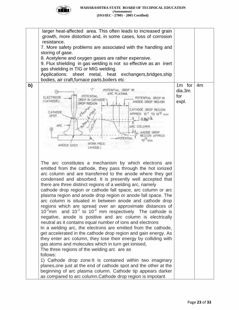
The arc constitutes a mechanism by which electrons are emitted from the cathode, they pass through the hot ionized arc column and are transferred to the anode where they get condensed and absorbed. It is presently well accepted that there are three distinct regions of a welding arc, namely cathode drop region or cathode fall space, arc column or arc plasma region and anode drop region or anode fall space. The arc column is situated in between anode and cathode drop regions which are spread over an approximate distances of 10-2mm and 10-1 to 10-2 mm respectively The cathode is negative, anode is positive and arc column is electrically neutral as it contains equal number of ions and electrons In a welding arc, the electrons are emitted from the cathode, get accelerated in the cathode drop region and gain energy. As they enter arc column, they lose their energy by colliding with gas atoms and molecules which in turn get ionised, The three regions of the welding arc are as follows: 1) Cathode drop zone:It is contained within two imaginary planes,one just at the end of cathode spot and the other at the beginning of arc plasma column. Cathode tip appears darker as compared to arc column.Cathode drop region is impotant
1m for dia.3m for expl.
4m

MAHARASHTRA STATE BOARD OF TECHNICAL EDUCATION (Autonomous)
(ISO/IEC - 27001 - 2005 Certified)
Page 24 of 33
2) Arc Plasma Column: Arc column is that portion of the welding are which is situated between anode and cathode drop regions.Arc column consists of a radiating mixture of electrons, ions ( + ) and highly excited neutral atoms and molecules. In order to keep current flowing between (the electrode and the job, or) cathode and anode (in DCSP) arc column provides and maintains, a regular supply of ions and electrons. 3) Anode Drop Zone: It is situated in between the anode spot and the place where the arc column finishes. This region forms the electrical connection between the arc plasma column and the anode. The potential drop in the anode drop region exists because of the concentration of electrons which enter in this zone from arc column.
c) -An alloy steel contains elements such' as chromium, nickel, vanadium, molybdenum, tungsten, cobalt, boron and copper; and manganese, silicon, phosphorus and sulphur in amounts greater than normally are present. - The purpose of adding alloying elements into steel is to achieve
Strengthening of the ferrite Corrosion resistance Better hardenability Grain size control Greater strength Improved machinability Improved high or low temperature stability Improved ductility, etc.
Oxy-acetylene Welding - The type of filler rod employed depends upon the mechanical properties required. A high tensile steel rod will prove effective. For corrosion resistance, etc., the weld metal must match with the parent metal. - A flux is used to counteract the oxidation of alloying elements. - After welding, a post heat-treatment is necessary for the heat treatable low-alloy steels to refine the grain structure.
4m 4m
MAHARASHTRA STATE BOARD OF TECHNICAL EDUCATION (Autonomous)
(ISO/IEC - 27001 - 2005 Certified)
Page 25 of 33
d
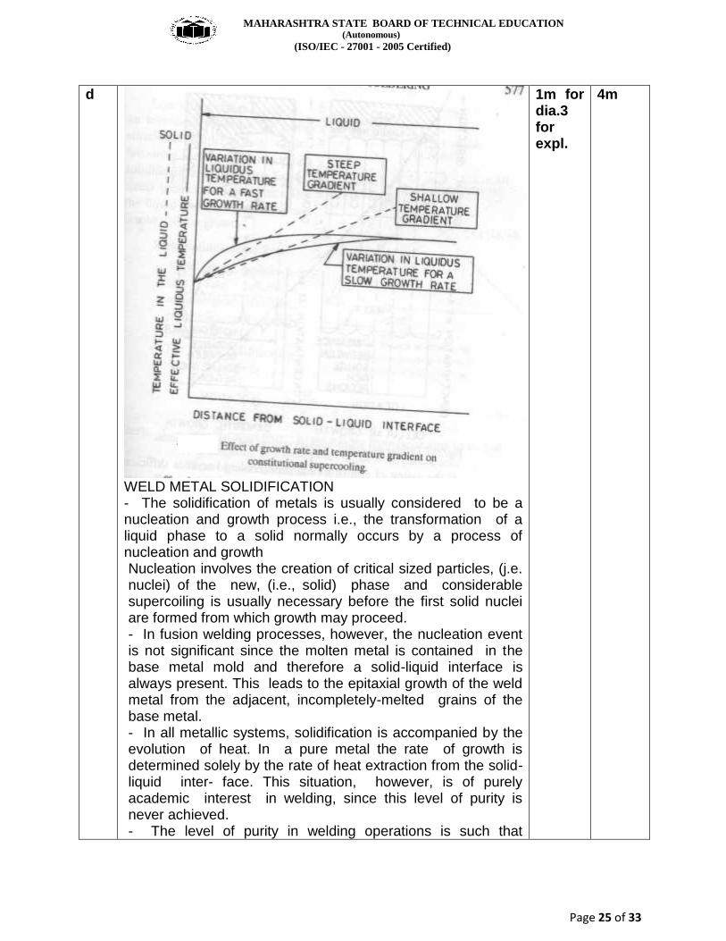
WELD METAL SOLIDIFICATION - The solidification of metals is usually considered to be a nucleation and growth process i.e., the transformation of a liquid phase to a solid normally occurs by a process of nucleation and growth Nucleation involves the creation of critical sized particles, (j.e. nuclei) of the new, (i.e., solid) phase and considerable supercoiling is usually necessary before the first solid nuclei are formed from which growth may proceed. - In fusion welding processes, however, the nucleation event is not significant since the molten metal is contained in the base metal mold and therefore a solid-liquid interface is always present. This leads to the epitaxial growth of the weld metal from the adjacent, incompletely-melted grains of the base metal. - In all metallic systems, solidification is accompanied by the evolution of heat. In a pure metal the rate of growth is determined solely by the rate of heat extraction from the solid-liquid inter face. This situation, however, is of purely academic interest in welding, since this level of purity is never achieved. - The level of purity in welding operations is such that
1m for dia.3 for expl.
4m
MAHARASHTRA STATE BOARD OF TECHNICAL EDUCATION (Autonomous)
(ISO/IEC - 27001 - 2005 Certified)
Page 26 of 33
Segregation always occurs on solidification. As the alloy cools through the solidification range, solute is rejected at the liquid inter face. - Since very little mechanical mixing of the liquid occurs in the immediate vicinity of the advancing interface, the rejected solute must be redistributed in the liquid by diffusion. - The freezing process is so rapid that diffusional processes cannot effectively remove the excess solute near the interface. Hence, solute enrichment occurs at the moving interface until a dynamic equilibrium is reached. The resulting dynamic equilibrium provides an excess of solute in the liquid near the interface with the solute content decreasing to the nominal liquid composition at some distance from the interface. As a result, the effective liquidus temperature varies with distance from the interface Three stages are :cathode zone,arc plasma zone,anode zone
e) SR.N
O.
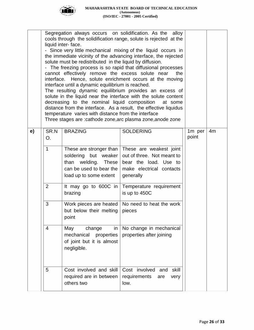
BRAZING SOLDERING
1 These are stronger than
soldering but weaker
than welding. These
can be used to bear the
load up to some extent
These are weakest joint
out of three. Not meant to
bear the load. Use to
make electrical contacts
generally
2 It may go to 600C in
brazing
Temperature requirement
is up to 450C
3 Work pieces are heated
but below their melting
point
No need to heat the work
pieces
4 May change in
mechanical properties
of joint but it is almost
negligible.
No change in mechanical
properties after joining
5 Cost involved and skill
required are in between
others two
Cost involved and skill
requirements are very
low.
1m per point
4m

MAHARASHTRA STATE BOARD OF TECHNICAL EDUCATION (Autonomous)
(ISO/IEC - 27001 - 2005 Certified)
Page 27 of 33
6 No heat treatment is
required after brazing.
No heat treatment is
required
7 Preheating is desirable to make strong joint as brazing is carried out at relatively low temperature
Preheating of workpiece before soldering is good for making good quality joint.
8 Cost involved and sill
required are in between
others two
Cost involved and skill
requirements are very
low.
9 No heat treatment is
required after brazing.
No heat treatment is
required
f)
Composition Of Electrode Wires of different chemical compositions and sizes are obtained from different steel manufacturers. In electrode making plant, they are chemically cleaned, cut to different lengths (300, 350, 450 mm etc.) and straightened. There are two methods of applying flux coating on the core wire, (a) by dipping, (b) by extrusion. Extrusion method is very fast and economical; produces strong uniform and concentric coatings and has largely replaced the dipping process. Coding: (1)American (AWS- ASTM) System
E XX XX or E 60 1 2 E XXX XX or E 100 1 5
Example E 60 1 2 (2) British (BS) System: L X X X L
2m classify 1m composition 1m coding
4m

MAHARASHTRA STATE BOARD OF TECHNICAL EDUCATION (Autonomous)
(ISO/IEC - 27001 - 2005 Certified)
Page 28 of 33
First letter 1st digit 2nd digit 3rd digit last letter Example: E317M E145P (3)Indian (IS) System: L X X X X X X L 1st letter 1st 2nd 3rd 4th 5th 6th last letter DIGITS Example:E307411
6) ATTEMPT ANY FOUR
4 X 4 16
a.
1)the combustion of acetylene in oxygen to produce a welding flame temperature of about 3100 °C is used 2) The torch mixes a fuel gas with Oxygen in the proper ratio and flow rate providing combustion process at a required temperature. 3) The flame temperature is determined by a type of the fuel gas and proportion of oxygen in the combustion mixture: 4500°F - 6300°F (2500°C - 3500°C). 4) Depending on the proportion of the fuel gas and oxygen in the combustion mixture, the flame may be chemically neutral 5) Oxygen pressures are approximately the same as acetylene pressures in the balanced pressure type torch. 6) The use of regulators to control gas flow and reduce pressure on both the oxygen and acetylene tanks Characteristic 1) Acetylene is safely stored at a pressure not exceeding 300 psi (2000 kPa) in special steel cylinders containing acetone. 2) Outside of cylinder acetylene is used at a absolute pressure not exceeding 30 psi (206 kPa). 3) Higher pressure may cause explosion. 4) Among the commercially available fuel gases, acetylene most closely meets all these requirements. Characteristic of oxygen (1) Commercial fuel gases have one common property: they all require oxygen to support combustion. To be suitable for welding operations, a fuel gas, when burned with oxygen, must have the following: (a) High flame temperature. (b) High rate of flame propagation. (c) Adequate heat content. (d) Minimum chemical reaction of the flame with base and filler metals. 2)The use dual oxygen and acetylene gases stored under
2m for process 2m per characteristic
4m
MAHARASHTRA STATE BOARD OF TECHNICAL EDUCATION (Autonomous)
(ISO/IEC - 27001 - 2005 Certified)
Page 29 of 33
pressure in steel cylinders, 3) Its ability to switch quickly to a cutting process, by changing the welding tip to a cutting tip,
b)
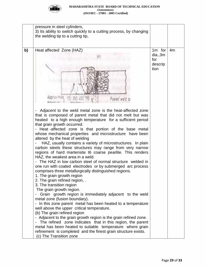
Heat affected Zone (HAZ)
- Adjacent to the weld metal zone is the heat-affected zone that is composed of parent metal that did not melt but was heated to a high enough temperature for a sufficient period that grain growth occurred. - Heat -affected zone is that portion of the base metal whose mechanical properties and microstructure have been altered by the heat of welding - HAZ, usually contains a variety of microstructures. In plain carbon steels these structures may range from very narrow regions of hard martensite t6 coarse pearlite. This renders HAZ, the weakest area in a weld. - The HAZ in low carbon steel of normal structure welded in one run with coated electrodes or by submerged arc process comprises three metallurgically distinguished regions. 1. The grain growth region 2. The grain refined region, . 3. The transition region The grain growth region. - Grain growth region is immediately adjacent to the weld metal zone (fusion boundary). - In this zone parent metal has been heated to a temperature well above the upper critical temperature. (b) The grain refined region - Adjacent to the grain growth region is the grain refined zone. - The refined zone indicates that in this region, the parent metal has been heated to suitable temperature where grain refinement is completed and the finest grain structure exists. (c) The Transition zone
1m for dia.,3m for description
4m
MAHARASHTRA STATE BOARD OF TECHNICAL EDUCATION (Autonomous)
(ISO/IEC - 27001 - 2005 Certified)
Page 30 of 33
In the transition zone. a temperature range exists between the lower critical temperature and upper critical temperature transformation temperatures (c) Unaffected Parent Metal - Outside the heat affected zone is the parent metal that was not heated sufficiently to change its microstructure.
c
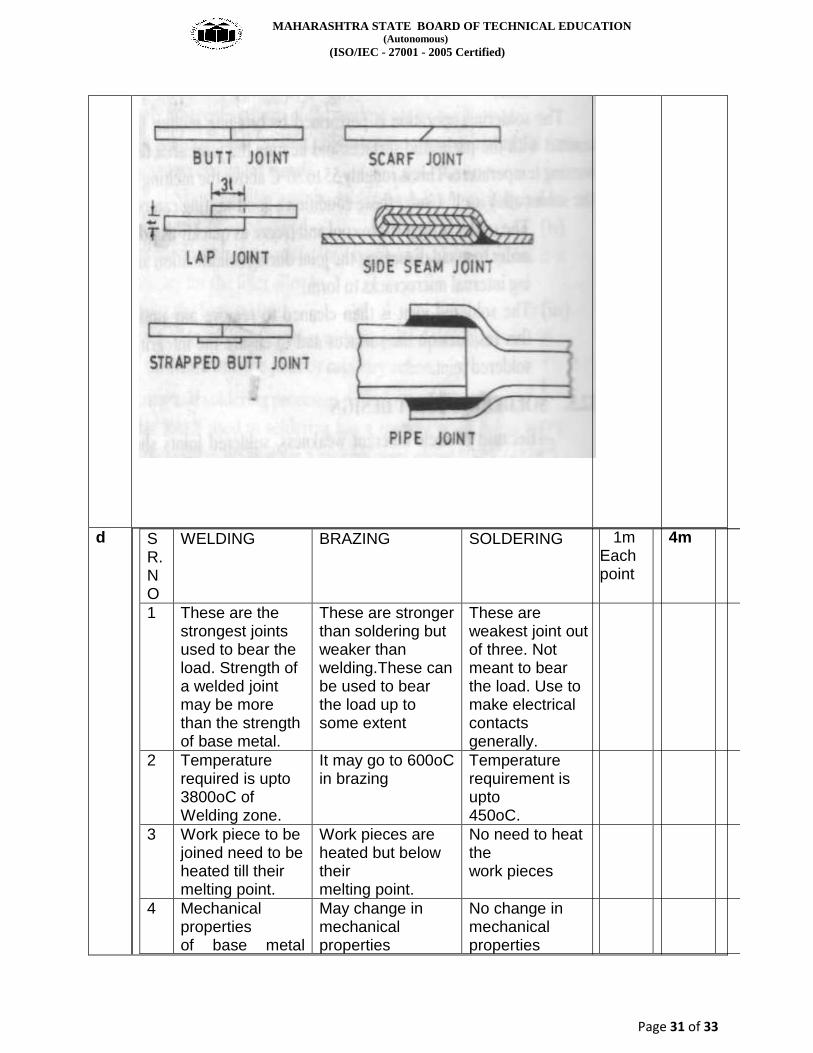
SOLDERING JOINT DESIGN
- Because of their inherent weakness, soldered joints should
be designed so that the base structure, not the soldered joint,
carries the load; or the load on the soldered joint is smallest.
-Strength to the soldered joints can, however, be provided by
shaping the parts to be joined so that they engage or interlock,
requiring the solder only to seal and stiffen the assembly.
While selecting a joint design the following factors should be
considered:
(i) Service requirements.
(ii) Method of heating to be employed.
(iii) Fabrication method used prior to soldering.
(iv) Number of components to be soldered.
(v) Method of applying the solder.
- A simple butt joint should be avoided as it is too weak to be
used alone. If the use of a butt joint is unavoidable, it is
advisable to use a strapped butt joint Corner and edge joints
should also be avoided. A lap joint is very widely used; it fits
more easily and achieves.adequate strength by extending the
lap shear area. In a lap joint, the overlap may be about three
times the thickness of the thinnest member.Even at best, the
lap joints are not so strong as lock-seamed, riveted or bolted
joints.
1m for dia.,3m for expl.
4m
MAHARASHTRA STATE BOARD OF TECHNICAL EDUCATION (Autonomous)
(ISO/IEC - 27001 - 2005 Certified)
Page 31 of 33
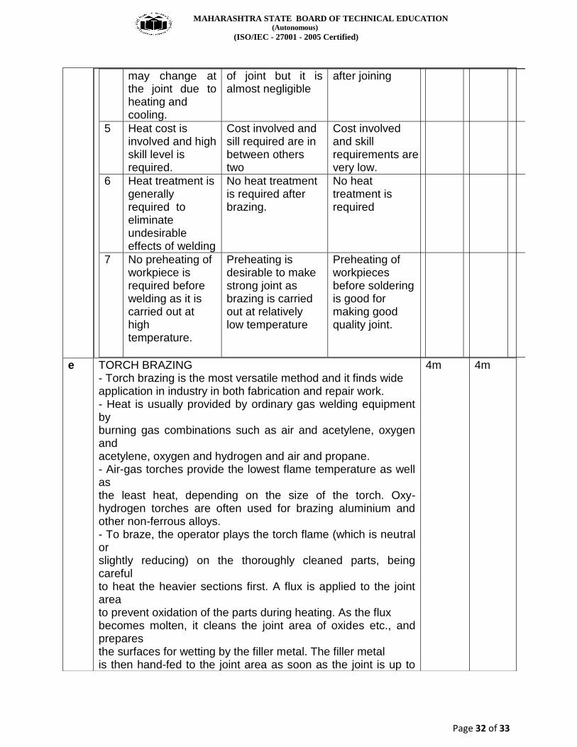
d SR. NO
WELDING BRAZING SOLDERING
1 These are the strongest joints used to bear the load. Strength of a welded joint may be more than the strength of base metal.
These are stronger than soldering but weaker than welding.These can be used to bear the load up to some extent
These are weakest joint out of three. Not meant to bear the load. Use to make electrical contacts generally.
2 Temperature required is upto 3800oC of Welding zone.
It may go to 600oC in brazing
Temperature requirement is upto 450oC.
3 Work piece to be joined need to be heated till their melting point.
Work pieces are heated but below their melting point.
No need to heat the work pieces
4 Mechanical properties of base metal
May change in mechanical properties
No change in mechanical properties
1m Each point
4m
MAHARASHTRA STATE BOARD OF TECHNICAL EDUCATION (Autonomous)
(ISO/IEC - 27001 - 2005 Certified)
Page 32 of 33
may change at the joint due to heating and cooling.
of joint but it is almost negligible
after joining
5 Heat cost is involved and high skill level is required.
Cost involved and sill required are in between others two
Cost involved and skill requirements are very low.
6 Heat treatment is generally required to eliminate undesirable effects of welding
No heat treatment is required after brazing.
No heat treatment is required
7
No preheating of workpiece is required before welding as it is carried out at high temperature.
Preheating is desirable to make strong joint as brazing is carried out at relatively low temperature
Preheating of workpieces before soldering is good for making good quality joint.
e TORCH BRAZING - Torch brazing is the most versatile method and it finds wide application in industry in both fabrication and repair work. - Heat is usually provided by ordinary gas welding equipment by burning gas combinations such as air and acetylene, oxygen and acetylene, oxygen and hydrogen and air and propane. - Air-gas torches provide the lowest flame temperature as well as the least heat, depending on the size of the torch. Oxy-hydrogen torches are often used for brazing aluminium and other non-ferrous alloys. - To braze, the operator plays the torch flame (which is neutral or slightly reducing) on the thoroughly cleaned parts, being careful to heat the heavier sections first. A flux is applied to the joint area to prevent oxidation of the parts during heating. As the flux becomes molten, it cleans the joint area of oxides etc., and prepares the surfaces for wetting by the filler metal. The filler metal is then hand-fed to the joint area as soon as the joint is up to
4m 4m
MAHARASHTRA STATE BOARD OF TECHNICAL EDUCATION (Autonomous)
(ISO/IEC - 27001 - 2005 Certified)
Page 33 of 33
the brazing temperature. - In many cases filler rods instead of being hand-fed,are preplaced in the form of a ring, washer, or insert to fit the contour of the joint. - Commonly used filler metals need a joint clearance(at brazing temperature) of 0.05 to 0.125 mm for capillary flow. Lap joints are usually preferred.
f
Gases used for TIG welding are: argon,helium,nitrogen -A shielding gas (argon helium, nitrogen, etc.) is used to avoid atmospheric contamination of the molten weld pool. -Their purpose is to protect the weld area from oxygen, and water vapour. Depending on the materials being welded, these atmospheric gases can reduce the quality of the weld or make the welding more difficult. - Only two of the noble gases, helium and argon, are cost effective enough to be used in welding. -Pure argon and helium are used only for some nonferrous metals. Semi-inert shielding gases, or active shield gases, include carbon dioxide, oxygen, nitrogen, and hydrogen. -Helium is lighter than air; larger flow rates are required. It is an inert gas, not reacting with the molten metals. Its thermal conductivity is high. -Helium normal gas for TIG welding is argon (Ar). Helium (He) can be added to increase penetration and fluidity of the weld pool. -Argon or argon/helium mixtures can be used for welding of all grades. In some cases nitrogen (N2) and/or hydrogen (H2) can be added in order to achieve special properties.
1m for naming 3m for desc.
4m