summer 2015 volume 29, issue 3 | issn 1069-2010 shot ... has enjoyed steady growth in its magnavalve...
TRANSCRIPT

Summer 2015Volume 29, Issue 3 | ISSN 1069-2010
Shot PeenerThe
Sharing Information and Expanding Global Markets for Shot Peening and Blast Cleaning Industries
Plus: IntroducIng “max “ ❚ what Is your machIne tryIng to tell you? ❚ PeenIng IntensIty selectIon ❚ keePIng Pace wIth change
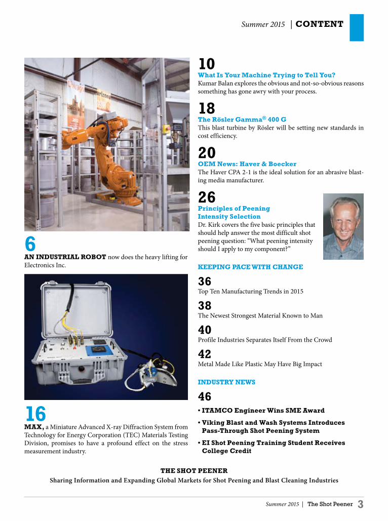
Industrial RobotNow Does the Heavy Lifting

Summer 2015 | The Shot Peener 3
Summer 2015 | CONTENT
10What Is Your Machine Trying to Tell You?Kumar Balan explores the obvious and not-so-obvious reasons something has gone awry with your process.
18The Rösler Gamma® 400 GThis blast turbine by Rösler will be setting new standards in cost efficiency.
20OEM News: Haver & BoeckerThe Haver CPA 2-1 is the ideal solution for an abrasive blast- ing media manufacturer.
26Principles of PeeningIntensity SelectionDr. Kirk covers the five basic principles that should help answer the most difficult shot peening question: “What peening intensity should I apply to my component?”
kEEPING PaCE WITH CHaNGE
36Top Ten Manufacturing Trends in 2015
38The Newest Strongest Material Known to Man
40Profile Industries Separates Itself From the Crowd
42Metal Made Like Plastic May Have Big Impact
INduSTRY NEWS
46• ITAMCO Engineer Wins SME Award
• Viking Blast and Wash Systems Introduces Pass-Through Shot Peening System
• EI Shot Peening Training Student Receives College Credit
THE SHOT PEENERSharing Information and Expanding Global Markets for Shot Peening and Blast Cleaning Industries
6 aN INduSTRIal ROBOT now does the heavy lifting for Electronics Inc.
16 MaX, a Miniature Advanced X-ray Diffraction System from Technology for Energy Corporation (TEC) Materials Testing Division, promises to have a profound effect on the stress measurement industry.

OPENING SHOTby Jack Champaigne | Editor | The Shot Peener
4 The Shot Peener | Summer 2015
THE SHOT PEENER
EditorJack Champaigne
associate EditorKathy Levy
PublisherElectronics Inc.
For a free subscription of the The Shot Peener, go to www.theshotpeenermagazine.com
The Shot Peener56790 Magnetic Drive Mishawaka, Indiana, 46545 USA Telephone: 1-574-256-5001 www.theshotpeenermagazine.com
The editors and publisher of The Shot Peener disclaim all warranties, express or implied, with respect to advertising and editorial content, and with respect to all errors or omissions made in connection with advertising or editorial submitted for publication.
Inclusion of editorial in The Shot Peener does not indicate that The Shot Peener management endorses, recommends or approves of the use of any particular commercial product or process or concurs with the views expressed in articles contributed by our readers.
Articles in The Shot Peener may not be distributed, reprinted in other publications, or used on the internet without the written permission of The Shot Peener. All uses must credit The Shot Peener.
keeping Pace with ChangeSOMETIMES CHaNGE is exhausting, sometimes it’s exhilarating.
Our new industrial robot exemplifies both sides of change. The implementation wasn’t fun but now that it’s installed, I enjoy watching the robot work. It makes the whole process of handling media so effortless and we definitely needed a faster way to test and calibrate MagnaValves. The improvements in our testing process will make an expansion of our product line so much easier. And so it goes.
The ever-quickening pace of technology developments gets tiresome. I love my electronic toys as much as anyone but when did the tablet replace the computer as the most popular web-searching device? Have you visited an older website that didn’t load quickly or properly on your smartphone or tablet? Truly, as soon as you launch your new website, you’d better be thinking about its next evolution. Profile Industries is doing a good job of staying on top of digital business trends. Read about their website and the eight things they’re doing right on page 40.
Your website is probably not keeping you up at night, but “disruptive innovation” might. If you’re unfamiliar with the term, Wikipedia explains it like this: A disruptive innovation is an innovation that helps create a new market and
value network, and eventually disrupts an existing market and value network (over a few years or decades), displacing an earlier technology. The term is used in business and technology literature to describe innovations that improve a product or service in ways that the market does not expect, typically first by designing for a different set of consumers in a new market and later by lowering prices in the existing market.
I wonder how soon the research and development of new metals will affect our industry...maybe in decades, maybe in years. Nonetheless, the accelerating pace of R&D is why we publish research on new materials in almost every issue of The Shot Peener. In this issue, we dedicated a small section to innovation and trends titled “Keeping Pace with Change.” Not only is it important to know what’s going on in R&D but most research is just plain interesting. Who knew that limpet teeth are now believed to be the strongest biological material? (See page 38.) Who knew limpets have teeth?
Even more rewarding is sharing product innovations from companies like TEC, Rösler and Haver & Boecker. We’re very fortunate that aerospace, automotive and medical companies—all advanced industries—depend on our services and push us to continually enhance our products and services. l
JaCk CHaMPaIGNE

Summer 2015 | The Shot Peener 5
Materials Testing Services
www.TECstress.com865.966.5856
Materials Testing Division • 10737 Lexington Drive • Knoxville, TN 37932 USA
When you use TEC’s accredited laboratory, you can be sure
that you will receive superior analysis and technical support.
We meet today’s strictest quality standards by maintaining A2LA
accreditation and ISO-9001 registration. Scheduled turnaround
of analysis results is always rapid, however, we can also adapt to
meet critical deadlines when you need immediate results.
Residual StressBy managing residual stresses during the manufacturing process, you and your customers can reduce failures caused by phenomenon such as fatigue and stress corrosion cracking.
Retained AusteniteWe calculate retained austenite using the four-peak method of measuring two austenite and two martensite peaks - recommended by both ASTM and SAE for obtaining accurate results.
In-House or Field ServicesUtilizing the portability of our own X-Ray Diffraction System, TEC lab personnel can perform measurements on parts ranging from a fraction of an inch to several hundred feet with guaranteed rapid and precise results.
At TEC, our customers are our partners. Our expert staff is
dedicated to helping you meet your own quality control demands.
Contact us today for more information.
ISOREGISTERED
9001

OEM NEWSElectronics Inc. | www.electronics-inc.com
6 The Shot Peener | Summer 2015
Industrial Robot Now does the Heavy lifting
EVERy MAgnAVAlVE® is flow-tested and calibrated to the customer’s required media type and size before it’s shipped. In the past, depending on the required flow rate of the MagnaValve, it was tested on a test stand with a hopper or an elevator. In either case, an Electronics Inc. (EI) technician was responsible for pouring the media into the hopper or elevator, monitoring the process and documenting the results. A flow test with an elevator could take up to four hours if the elevator had to be cleaned because the next MagnaValve required a different media.
There’s Got To Be a Better Way EI has enjoyed steady growth in its MagnaValve product line, but they were coming up on a problem. Most wheel-blast machine MagnaValves required a test stand with an elevator due to their high flow rates. MagnaValves for air-blast machines could be calibrated on a test stand with a hopper but since a customer orders multiple units for one machine, prepping air-blast machine MagnaValves for delivery was just as time consuming as prepping wheel-blast machine valves. EI technicians were spending too much time handling media and monitoring the test stands, and there was always the risk of media contamination in the elevator. In addition, the elevator was noisy and distracting to workers in the nearby Almen strip testing station. Most importantly, EI wanted to eliminate the safety hazards associated with lifting media and, even though EI maintains an extremely clean plant floor, there was always the chance for media spillage that could result in falls. A material-handling robot became the obvious solution.
“Shotzie” the Robot Takes Center Stage“Shotzie,” so named in an employee contest, was installed in early 2015. The industrial robot navigates in the center of a circular testing station with shelves for containers of media and two testing platforms with hoppers—one for air-blast machine valves, one for wheel-blast machine valves. The hoppers can hold 100 to 700 pounds of media. Tests for both types of valves can run at the same time and the test platforms allow easy access to the MagnaValves so they can be changed quickly. During a test, the robot picks the correct media and pours it into the hopper. If the test requires a large volume of media, Shotzie picks up the media bucket from under the test platform and pours it back into the hopper. A process that
once took up to four hours is now completed in 20 minutes with no risk of injury to employees or chance of media contamination.
The Advantages of a PLC-Driven RobotBecause it is PLC driven, Shotzie has additional advantages such as common programming controls, software interfaces, backup and restore methods, and program documentation. EI’s engineering team wrote the operating procedure and they didn’t have to learn a robot programming language to do it. Technicians program the test and then go back to other tasks.
Shotzie, the EI industrial robot, lifts a bucket of media up to a hopper while Bryan Chevrie, an EI engineer, watches.


OEM NEWS Continued
8 The Shot Peener | Summer 2015
Every MagnaValve’s test results are saved and stored. The system has one control panel with HMI (Human Machine Interface) and AC-24 and FC-24 controllers.
Clean Media, Clean FloorIn Shotzie’s work area, there are 50 containers of several sizes of four kinds of media (cast steel shot, conditioned cut wire, special conditioned cut wire, and stainless steel conditioned cut wire). Each container is covered by a shelf to prevent airborne contamination. In addition, EI maintains an inventory of grit, shot for specific customers, custom blends, and other special media (microbead, ceramic, aluminum oxide, glass bead), totaling 75 different medias. The work station is quiet, clean and safe and every container holds pure, clean media.
The Benefits to the Customer“We didn’t want to get to the point where we couldn’t keep up with demand or have to sacrifice quality,” said Tom Brickley, Vice President of Electronics Inc. “Now we can calibrate a valve and get it back to a customer in 24 hours upon request.” Since Shotzie has come on board, EI is looking forward to increasing productivity and ramping up its research and development of new MagnaValves. l
The control console has a large monitor and holds several EI controllers. Bryan Chevrie demonstrates how easy it is to install a MagnaValve.
Shotzie “presents” the media for inspection. A SWECO ensures that the media is kept in top condition.

Summer 2015 | The Shot Peener 9
High precision peening equipment for automotive
www.wheelabratorgroup.comNorican Group is the parent company of DISA and Wheelabrator.
Whether you are peening large areas with centrifugal wheels or targeting specific areas with programmable airblast nozzles, Wheelabrator equipment will enable you to comply with industry specifications and production requirements.
Contact us to find out how. US: 800-544-4144 • Canada: 800-845-8508 • [email protected]
Peening solutions

10 The Shot Peener | Summer 2015
BEST PRaCTICESby Kumar Balan | Engineer | Empire Abrasive Equipment
What Is Your Machine Trying to Tell You?If YOu aRE REadING THIS, there is a good chance you work in Aerospace, Automotive or a similar advanced manufacturing sector. You might be engaged in shot peening, grit blasting, etching or another value-added surface preparation operation on your component. Furthermore, if your machine is less than ten years old, and automated, it likely has a PLC, HMI and diagnostics to help you identify, or at least narrow down, issues when they arise. With all that taken into consideration, most users of shot peening and blast cleaning equipment will also agree that there are more than the obvious reasons and causes when it comes to machine issues. Just as it is difficult to quantify what “exactly” happens to each pellet of abrasive after it leaves the blast nozzle or wheel, the same is true for the machine and process feedback we receive during regular use. Our discussion will focus on some of the machine feedback and categorize it as having obvious or not-so-obvious causes. When we do so, let’s bear in mind that peening and cleaning machine technologies continue to evolve. The process variables are constantly impacted in positive ways by technological advancements, and the resulting machine performance will be a continuing debate.
Problem: Media Leakage Around the MachineMost of us share the same opinion on the propensity of cleaning and peening machines to leak abrasive. An astute, albeit facetious, solution that many offer to this ancient problem—stop adding media and this problem will go away! Unfortunately, this solution isn’t very practical. Media leakage can occur in multiple locations in the machine. Typical areas are through openings such as work doors, access doors, the roof of the cabinet and near the reclaim system components. Each location has its own reason(s) for leaking media. A well-designed machine will attempt to direct media from a nozzle or blast wheel away from an access door, work door or protected opening (Fig. 1). In addition, most cabinets are lined with wear-resistant material for protection from the incidental media stream or rebound media bouncing off the component. However, these features don’t always prevent media leakage and then we must look into the causes.
Obvious causes1. Faulty/worn nozzle holding arrangement or worn blast
wheel part (typically the control cage or blades) that misdirects the abrasive towards the cabinet opening
2. Worn door seals or curtains (in the absence of doors) that allow abrasive to escape the cabinet
3. Worn seal on the cabinet roof slot provided for the purpose of nozzle carriage arm entry into the cabinet
4. Sharp radius of the blast hose resulting in rapid wear in tight areas, softening of the hose and an eventual tear
5. Loose hose fittings and gradual dislodgement at connection points
For the not-so-obvious causes of media leakage, let’s start with a real-life occurrence: A customer who shot peens a high volume of automotive
components reported that passersby in an aisle behind the machine were being hit by abrasive. Though this is not uncommon when standing in front of a badly leaking machine work door, in this case there was a solid machine cabinet wall in back of the machine where the leakage was reported. Within a few hours of machine usage, this leakage got more pronounced and a narrow opening was visible in the wall. The culprit was a cabinet liner that had come loose in the rebound area inside the blast cabinet, exposing the bare wall to abrasive impact. At 300 feet per second (91 meters per second), it did not take long for damage to exacerbate.
Fig 1. Nozzles targeting specific areas on the component and away from the door.

11 The Shot Peener | Spring 2015
Clemco International Group –new look - same mission
Clemco was founded in the USA in 1949 with the joint goals of providing revolu-tionary high-production abrasive blasting technology, and of setting a new standardfor product quality, maximum effi ciency, and operator safety and comfort. This commitment to our customers remains unchanged year after year.
www.clemco-international.com
Engineered by Clemco
Global engineering –Trusted solutions
get in touch
BEST PRaCTICES Continued
12 The Shot Peener | Summer 2015
From every peening workshop we have attended, we have learned that the abrasive particle loses very little of its impact energy within the first few rebounds. Moreover, we also know that less than 100% of the media stream hits the target. The percentage that doesn’t hit the part could be hitting a liner or deflector that is likely misdirecting abrasive towards a cabinet opening. The same holds true for parts with complex geometries and features that tend to deflect the abrasive as they spin on a satellite table.
Other not-so-obvious causes1. Another classic source of leakage, typically on the cabinet
roof, is from abrasive escaping through the air inlet. Steel shot, given its spherical shape, commonly exhibits this tendency, more so with smaller shot sizes such as S70 and S110. The round profile of steel shot allows it to effortlessly roll along the walls of the air inlet and make its way outside the cabinet. The solution could be a taller air inlet and multiple layers of internal baffles.
2. In an airblast machine with vacuum recovery, the media stream from the cabinet (reclaim duct) enters the reclaimer at almost 4500 feet per minute or greater. The tangential entry into the reclaimer is the first point of potential wear. Most reclaimers are built with wear plates at this first point of entry and lined with wear-resistant material where the media swirls. It is critical that the wear plate be inspected regularly for erosion or damage.
The most serious consequence of media leakage is that it’s a safety hazard due to injuries from falls. Other problems include:• Loss of media (if leaked media is recycled back into the
machine, it should be thoroughly cleaned offline of large size contaminants before reuse)
• Insufficient coverage (particularly in peening applications)• Longer cycle times
Problem: Finished Part (Peened or Cleaned) Has a Brown ResidueAn aerospace customer complained that their shot peening process gave repeatable results but the parts exited the machine with a rust-colored coating on them. The diagnosis commenced with examining the obvious areas of concern. Being a wheelblast machine with high flow rates, it had a mechanical reclaim system with an airwash separator. The separator openings, the velocity of ventilation stream and all other obvious areas were checked and eliminated as possible culprits that could cause discoloration. Another potential problem area was the initial condition of the parts. Any oil or moisture on the part could lead to abrasive contamination and potential discoloration of the finished product. This reason was eliminated, too, since the parts were completely dry when introduced to the machine. Upon further investigation, it was discovered that the machine had not been used for an extended period of time. If a machine is mothballed for time periods greater than two to three weeks, abrasive left in the machine could develop flash rust and transfer the rust to the component being blasted. In addition, rust from the insides of reclaim system components could also enter the media stream and cause further contamination. Two possible solutions are recommended, with the first preferred over the second. A machine should never be idle for extended periods of time. It should be operated with blast media for at least an hour or two every five to seven days, more frequently in humid environments. This keeps the abrasive in circulation and reduces the possibility of rusting. The second method is to clean out all the abrasive from the machine and store it in a dry location. However, this doesn’t eliminate the possibility of reclaim system transfer rust.
Problem: Process Parameters Haven’t Changed but Arc Heights Have DroppedThis is a common complaint from regular users of this process. Most of these users are aware of potential causes, but lose track of them when focusing on routine production tasks. However, we know that all peening processes are critical and the implications of a non-repeatable process can be disastrous to the end product.Obvious causes1. Air pressure in a nozzle machine and wheel speed in a
wheel machine are directly proportional to arc height (and intensity). A drop in air pressure or wheel speed will result in reduced arc height. Air leakage, faulty PID loop for air pressure, or faulty speed controller (inverter) in a wheel machine are some of the common causes.
2. Blades that are too short were installed in a wheelblast machine during machine maintenance and blade replacement. Media velocity is directly proportional to the wheel diameter.
A lip below the access door will reduce media leakage onto the floor.

Spring 2015 | The Shot Peener 13
E
ngineering
YOUR
Competitive Edge
Empire Abrasive Equipment, 2101 W. Cabot Blvd., Langhorne, PA 19047-1893
Call: 215.752.8800 • Fax: 215.752.9373 • Email: [email protected]: www.empire-airblast.com
Empire Abrasive Equipment, the leader
in air-blast technology for over 70 years,
engineers winning solutions to finishing
challenges by supporting top-flight human
talent with state-of-the-art manufacturing
and testing facilities.
If you prep or profile, clean or
peen, you can count on Empire for the
competitive edge.
Precision Cleaning
ID Peening
Robotic Repeatability

BEST PRaCTICES Continued
14 The Shot Peener | Summer 2015
3. The wear of nozzles and hoses will impact arc height. Similar results can be expected with wear of wheel components such as blades, control cage and impellers.
Not-so-obvious causesA customer in aerospace had a very efficient peening operation with over 20 Almen blocks in a part verification tool (test fixture). The customer maintained arc heights within 0.002" over the set of Almen strips. After several years of peening with this stellar record, they started experiencing a drop in arc heights even though all parameters remained unchanged. Several days of fault diagnosis bore no productive result until it was disclosed that they were trying out a new media supplier. The new media supplier was supplying media that conformed to SAE specification so this is not to say that the new media was of poor quality. Though seemingly innocuous, it simply means that any change in media could lead to different impact energy, possibly because of a difference in the metallurgy of the metal. Process parameters will require tweaking and new saturation curves will need to be plotted.
Other not-so-obvious causes1. Wrong type of Almen strips used for testing (A instead of
N, or C instead of A). There is also the possibility of a faulty Almen strip due to a manufacturing error.
2. Change in the hardness of the part. This reason doesn’t necessarily belong in this category since we only peen strips for verification and not the actual parts, but yet worthy of mention in context. However, it is important to note that given the same set of process parameters, a hard part will bear different results than a softer part when peened. This is amply demonstrated in coverage times and residual stress results.
3. The Almen gage needs to be calibrated.
Problem: Process Parameters Haven’t Changed but Cycle Time Has Increased or Coverage Is InsufficientArc height (i.e., intensity) is a function of air pressure, wheel speed or wheel diameter; it has nothing to do with the actual part. Coverage and cycle time (the latter in cleaning applications) is observed on the part and is a function of the amount of abrasive propelled onto it (lb/minute or kg/minute). Other than specific applications where high flow rates could result in flooding the part, an increased flow rate will generally result in a shorter cycle time in most applications. Increased flow rates have different reactions in a wheelblast and airblast machine, where it has to be matched with proportional changes to air pressure (in the air-blast machine). Here are some of the obvious and not-so-obvious causes:
1. Is the part now made from a harder material?
2. Has there been a change in your media supplier or abrasive quality?
3. Have you changed the size of the abrasive? Smaller abrasive provides better coverage. (2:1 Size = 8:1 Impact Value and 1:8 pellets/lb. Source: Effective use of steel shot and grit for blast cleaning, E.A. Borch, Ervin Industries, Inc. April, 1999)
4. Issues with the work-handling arrangement such as a slipping belt that improperly presents the part to the blast nozzles/wheels, a faulty bearing, a broken chain, etc.
It’s advisable to conduct a Media Catch test for each nozzle and blast wheel in your machine to validate the results and ensure consistency.
SummaryOur discussion here merely scratches the surface of the issues you face in your blast cleaning or shot peening operation. Such is the nature of cleaning and peening. Importantly, the point of this article is to recognize that there is more than the obvious when it comes to recognizing the causes of common machine issues. If the problem is sorted out by addressing the obvious, that might be it. However, recurrence indicates that you have to drill deeper, and the past may not necessarily be a good predictor of the future when it comes to fault diagnosis. Blast cleaning and shot peening machines follow very basic principles. With a clear understanding of the relationship between mass, velocity and resulting impact energy, you will be on the right track to correcting issues that surface with your machine during routine operation. l
The Role Played by SpecificationsWhen taking a honest look at the process and equipment, it’s not uncommon to conclude that there is still sufficient mystery in its operation. This mystery, particularly in shot peening, is not desirable. This is where we can take refuge in established specifications because they have been created with the intention of providing uniformity and repeatability to your process.
For example, AMS 2430 clearly identifies every aspect of a peening process including media quality, media maintenance in your machine, the plotting of saturation curves, and more. Following this document will help pinpoint machine issues before they become catastrophic to the end product.
Specification conformance is onerous, but the cost of non-conformance is much higher. Faulty machine design, however, cannot be fixed by specification conformance. Therefore, a thorough knowledge of relevant specifications will help you identify the features you need in a machine before making a purchase.

Summer 2015 | The Shot Peener 15
Innovative Peening Systems IPS....
Fanuc CNC Controlled
S SeriesFive Axis CNC
Computer Controlled Shot Peening Machine
Part Capacity 24” dia x 36” high
L SeriesSix Axis CNC Computer Controlled Shot Peening Machine
Part Capacity 48” dia x 48” high
Rotary Lance
CNC is no longer exclusive to the Fortune 500Our affordable CNC machines allows every shot peener to eliminate manual nozzle setups. CNC offers exceptional part processing speeds, accuracy of peening and consistent quality of parts.
Innovative Peening Systems 2825 Simpson Circle Norcross, GA 30071
770-246-9883

16 The Shot Peener | Summer 2015
PROduCT dEVElOPMEnTTEC Materials Testing Division | www.tecstress.com
Compact Performance under Pressure!
TECHNOlOGY fOR ENERGY CORPORaTION’S (TEC) Materials Testing Division proudly introduces MAX, a Miniature Advanced X-ray Diffraction System, which promises to have a profound effect on the stress and retained austenite measurement industry. TEC meets customer needs and offers unparalleled compatibility, convenience, and reduction in time and costs with this compact, portable device for measuring surface residual stresses in previously inaccessible locations. This innovative, powerful new product was developed under an Air Force SBIR program to measure residual stresses in hard-to-access locations on aircraft. The miniaturized system measurement head fits within a space 8 inches in diameter and uses x-ray diffraction to measure stresses in common engineering materials. This third generation version of miniature diffractometers now uses the sin2 Ψ technique which improves the precision of the measurement. This system is unique in its ability to measure retained austenite in accordance with ASTM E975. MAX’s versatility in other industrial and real world applications seems limitless. It is compact, effortless and accurate. The MAX system consists of hardware and software packaged in two rugged traveling cases plus a laptop PC. The hardware contains a measurement head, safety system and electronics. The measurement head includes a low-powered x-ray tube with a 4-Watt high-voltage power supply and a miniature position-sensitive proportional counter (PSPC) detector. Data obtained by the detector are analyzed with re-designed electronics that incorporate the capabilities of a full-sized electronic module on two integrated circuit boards. The measurement head is small enough to fit inside an 8-inch opening. Accurate measurements can be made in as few as 2-3 minutes. Designed for field use, MAX only requires 110V/15A service. The entire system is controlled by software from a laptop computer. Rigorous peak fitting routines provide excellent data analysis for this low-powered system. Users may choose from several commonly used routines to optimize analysis accuracy. Software guides the user through the entire measurement and analysis routines with simple, easy-to-use visual guides. An interlocked optical beam provides a barrier to protect personnel from the emitted x-rays during system operation. The addition of retained austenite measurement capability makes MAX a versatile tool for any industry using ferrous materials (steels and cast irons). MAX uses the “4-peak” method which measures two separate austenite and two separate martensite/ferrite peaks. The measurement of at
least two different austenite peaks is required by ASTM E975.MAX can measure engineering metals and ceramics through the proper combination of x-ray tubes and detector positions. Currently, chromium and copper x-ray tubes are available. Additional tubes may be available in the future. MAX has the ability to measure diffraction peaks in the high back-reflection region of 120˚ to 170 .̊ This innovative new product will be available later this year. l
The MAX system is portable and compact for measuring previously inaccessible locations.
The Max measurement head fits easily within an 8-inch diameter space.

Winter 2013 | The Shot Peener 17
MagnaValve®
COLORS
BLACK PANTONE 130
Media valves for air-blast and wheel-blast machinesReduces labor, media and energy costs while adding control and reliability
to shot peening and blast cleaning processes
24 Vdc MagnaValves for air-blast
machines
24 Vdc MagnaValves for wheel-blast machines
NEW! Non-ferrous media MagnaValve for air-blast machines
1-800-832-5653 or 1-574-256-5001 www.electronics-inc.com
MagnaValve is a registered trademark of Electronics Inc.
You can depend on itThe unique design of the MagnaValve makes it one of the most reliable and
hard-working media valves on the market today. Other benef its include:❚ Flows most ferrous media and introducing a new model for non-ferrous media
❚ MagnaValves have companion controllers for accurate and dependable media flow control
❚ Compliance to specif ications is readily attainable❚ Available in 24 Vdc and 120 Vac
❚ Trusted by OEMs and end-users worldwide

18 The Shot Peener | Summer 2015
OEM NEWSRösler | www.rosler.com | +49-9533-924-0
The Rösler Gamma® 400 GSHOT BlaSTING for surface cleaning and surface preparation represents an indispensable manufacturing phase in many metal-processing industries. Generally, blast turbines are the most expensive component of many shot blasting systems, requiring significant upkeep in terms of maintenance and wear parts. At the GIFA exhibition in Duesseldorf, Rösler presented its newly developed and extremely versatile Gamma® 400 G blast turbine which will be setting new standards in cost efficiency. For example, compared to conventional turbines, the Gamma® 400 G offers a 100% higher uptime and a significantly improved blast performance together with drastically reduced maintenance costs. Distinctive features of the Gamma® 400 G are the Y-shaped throwing blades, providing many technical advantages for this innovative turbine, for which a patent application is pending. By simply turning the blades around, both sides of the throwing blades can be utilised. This design helps double the uptime and results in drastically lower wear part costs.
Quick and simple exchange of the throwing bladesWith conventional twin disk blast turbines, the replacement of worn throwing blades is complicated and time consuming. The impeller and control cage must be completely disassembled before the old blades can be loosened, removed and new blades inserted through the center of the twin disks. With the new Gamma® turbine design, the worn throwing blades can be easily loosened, taken out from the side and replaced with new blades after simply removing a maintenance side cover. This quick blade exchange with easy access to all wear components makes turbine maintenance not only simple but also saves a significant amount maintenance time, further helping to increase that all important uptime and reduction in operating costs.
Blast performance improvement by 15% - 20%Another key feature of this unique blade design is the improved turbine efficiency. Compared to straight blades, the curved throwing blades of the Gamma® 400 G allow a much more fluid flow of the blast media. Without increasing the turbine diameter this improves the media acceleration and produces significantly higher throwing speeds. The end result: A 15%-20% percent higher blast performance with, subsequently, shorter processing times for many shot blasting applications!
Flexible turbine drive power and media throughputThe new Rösler blast turbines have a diameter of 400 mm (about 16"). They can be equipped with drive motors from 11 up to 30 kW and generate media throughputs of up to 400 kg/min (880 lb/min). With this wide range of power options, the Gamma® 400 G is suitable for practically any shot blasting application. The Y-blades are produced by a special manufacturing process that also allows fabricating the turbine components in a highly wear resistant tool steel. Rösler GmbH is an international market leader in the production of surface finishing, shot blasting machines, painting systems and preservation lines as well as process technology for the rational surface finishing (deburring, descaling, sand removal, polishing, grinding…) of metals and other components. Besides the German plants in Untermerzbach and Bad Staffelstein, the Rösler Group has branches in Great Britain, France, Italy, The Netherlands, Belgium, Austria, Switzerland, Spain, Romania, Russia, China, India, Brazil, South Africa and USA. l
After simply removing a maintenance side cover, the throwing blades can be easily exchanged. Mr. Jan
Reinmann, R&D manager at Rösler, explains: “Compared to conventional turbines, the technical and economic
advantages of our new turbine design are so convincing that within the near future we will introduce a version
with a diameter of 300 mm (about 12").


20 The Shot Peener | Summer 2015
OEM NEWSHaver & Boecker | www.haver-partikelanalyse.com/en
The HAVER CPA 2-1 Is the Ideal Solution for an Abrasive Blasting Media Manufacturer
ABRASIVE BlASTIng uses many different compositions and particle sizes of abrasive for a wide variety of applications. Examples include cleaning, rust removal, matting, and surface hardening. Users do not only distinguish between the size and shape of the particle, from cubic to almost spherically round, they also analyze the abrasive blasting material’s compliance to the normative quality requirements or how much it exceeds them. As a manufacturer of abrasive blasting media, VULKAN INOX GmbH has to meet these requirements. The company, founded in 1985, is in Hattingen, Germany. It produces and markets cast stainless steel abrasive blasting and special granules based on iron-carbon alloys and it is certified to EN ISO 9001:2000. The production of abrasive blasting media for the surface treatment of screws is just one example of the application-related products developed by the company. This application requires a uniform surface that provides conditions suitable for an anti-corrosion coating. In order to achieve the defined roughness of the screw surface, the abrasive blasting agent Chronital S10 with a grain size of 90 µm to 200 µm is used (Fig. 1). The special feature of this premium value stainless steel abrasive blasting agent is that the maximum size of 200 µm is not exceeded. Together with a good circularity of at least 95% of the particles, this fulfils the most essential requirements for optimum processing of the screws. In addition to the size distribution, precise shape
accuracy is essential in the analysis. These specifications were previously checked using traditional sieve analysis and a visual examination of a small amount of material. Because the results of this shape analysis are considered to be more subjective and thus vary from person to person, VULKAN INOX GmbH purchased a HAVER CPA 2-1. The
Fig. 1. Abrasive blasting material Chronital S10 with shape values over the normative standard is used for the surface treatment of screws. The standard assures short blasting times in addition to long lifetimes.
The figure shows the macroscopic and microscopic imaging of the Chronital material with an example excerpt from the particle list from the HAVER CpaServ software.
Fig. 2. The result of three analyses of the abrasive blasting agent Chronital S10 using the HAVER CPA 2-1. The throughput distribution (Q3[V-%]) clearly shows that
the main part of the abrasive blasting media is made up of particles with a size between 90 and 200 µm. Also for very narrow distribution ranges, the smallest differences
and deviations are clearly shown by the various depiction possibilities that are offered by the HAVER CpaServ.

Summer 2015 | The Shot Peener 21
NATIONAL PEENINGSINTOKOGIO GROUPTel 800-325-7336www.nationalpeening.com
TM
Brand Design Guidelinesブランドデザインガイドライン
Peening Solutions ForAEROSPACE AUTOMOTIVE MEDICAL
POWER GENERATION
Now with Contract Peening Resources!
ONE GLOBAL SINTO

OEM NEWS Continued
22 The Shot Peener | Summer 2015
precision and reproducibility of results is excellent for this dynamic image analysis. Also, the speed at which the HAVER CPA analyses large abrasive blasting materials is impressive due to its wide channel and high-resolution camera. HAVER CPA technology enables all particles to be measured and evaluated in real time. Even the finest differences are measurable. The HAVER CpaServ software performs the check and assessment of the shape and size using a variety of possible size and shape definitions (Figs. 2 and 3). The results provided by the HAVER CPA unit contribute to optimising production control. Whilst the S10 particle size can be regulated by the application of pressure during spraying in the production process, granulation and circularity are highly dependent on the melting process. Over the option of the particle list, the results of the abrasive blasting media analysis and a graphic display of each article can be carried out, checked over, and proven. Additionally, VULKAN INOX GmbH can analyze the abrasive blasting media online. Like all HAVER CPA systems, the HAVER CPA 2-1 is prepared for online measurements and can be utilised for automatic checking of production. The HAVER CPA 2-1 ONLINE, which is continuously ready for measurement, is connected with a sample taker that continuously extracts abrasive blasting material during the running process. The sample taker and the CPA unit may be activated either by a memory-programmable controller or manually. The sample can returned directly into the process after measurement. Precise results from the HAVER CPA, with just a short measurement time, allow VULKAN INOX GmbH to continue to offer an assured level of abrasive blasting material quality despite increased requirements by the users. It allows production to benefit from optimisation and the optional connection in an inline and online application. l
Fig. 3. The result of three samples of the abrasive blasting agent Chronital S10 using the HAVER CPA 2-1. The
residue distribution (1-Q3[V-%]) clearly shows that with good samples (yellow and orange) over 95% of the abrasive
blasting media is made up of particles with a circularity of over 0.86. The deviation clearly shown here cannot be
detected using a manual optical check.
For the size and shape analysis of abrasive blasting material, the HAVER CPA 2-1 with a measurement range
starting at 0.034 mm and a channel width of 65 mm is suitable for rapid and reliable analysis.
The HAVER CPA 2-1 ONLINE (with maintenance and control unit and a notebook housing) can be used for the
automatic check of abrasive blasting material production.
About HAVER & BOECKER
HAVER & BOECKER is a traditional family-managed, midsize company with headquarters in Oelde, Westphalia, Germany. The Wire Weaving and Machinery Divisions are under the umbrella of HAVER & BOECKER OHG. Together with over 50 subsidiary companies on all five continents, they make up the HAVER Group which has more than 2,898 employees and 150 representatives. In 2014 the HAVER Group posted a sales turnover of 428 million euros.

23 The Shot Peener | Spring 2015
1-800-832-5653 or 1-574-256-5001 | www.electronics-inc.com
Electronics Inc. – The Almen Strip Experts Since 1987
Introducing ourDouble-Sided Numbered Almen Stripswith Coverage Check Finish*
The Electronics Inc. Almen strip lot number is now printed at the top of both sides of our Numbered Almen Strips with Coverage Check Finish.* This insures that you always have a legible lot number and plenty of room to add your own notes.
Printing our lot number on both sides of the strips is just one more way our Almen strips contribute to a validated shot peening process.
* U.S. Patent No. 6,568,239 for Coverage Check Finish
Our grading system (3™, 2™, 1™, 1S™) makes it easy to choose the best strips for your shot peening process including automotive, aerospace and medical applications.
Electronics Inc. maintains a large inventory of Almen strips to insure fast delivery around the world.
We are responsible for every aspect of the manufacturing process to ensure that EI Almen strips qualify to industry specs from standard MIL to aerospace specifications.
Ask for the results of our Almen Strip Consistency Testing Program. We can prove that our strips are nearly identical in lot-to-lot arc height results from month to month, year to year.

24 The Shot Peener | Spring 201524 The Shot Peener | Spring 2014
Engineered Abrasives®
Manufacturers of the Finest Blast Finishing and Shot Peening Systems
(708)389-9700 or (773)468-0440Email: [email protected] Web: www.engineeredabrasives.com
ISO/TS16949ISO 14001FORD Q1Certified
Job Services
Engineered Abrasives® index units are the most durable machines on the market today with all our special features
All Engineered Abrasives® systems are available with the EA® Knowledge System®. The EA® Knowledge System® features computer animation on machine operation and maintenance, including how to do Almen Strips.
60" Index UnitRing and Pinion Gears
for High Volume
8 Pressure Nozzleswith MagnaValves®,Buck Elevator, Sweco
and Dust Collector
Patented 72’’ Index Unit with Shot Flow Controls, Sweco, Bucket Elevator, 8 Nozzles and 16 Spindles. Designed for high-volume shot peening.
®
Look for RED components and surfaces to be sure you get Engineered Abrasives® quality equipment and OEM parts.
All Tooling and Fixtures A2 Tool Steel hardened to 62 RC
Engineered Abrasives® High-VolumeIndex Unit with complete Material Handling and Robotic System
▲
®

25 The Shot Peener | Spring 201525 The Shot Peener | Winter 2015
The largest 5-Axis CNC 96" Shot Peening Index Table made. Two-media capacity with MagnaValves® for large rings and pinions up to 33" O.D. Designed for higher volumes. (GE 31-i Series Controller)
Large 84" Index Unit for
high volume
12 Pressure Nozzles with
MagnaValves®
Automatic load/unload1,000 gears per hour
Single Cell Unit, 5 Pressure Nozzles Large 84" Index Unit, 12 Pressure Nozzles
Bucket Elevator Sweco System MagnaValves®
6 Spindles each station for high
volume
Dual Swing Doors for higher volume
▲▲
▲▲
ENGINEERED ABRASIVES®, EA, the stylized EA® logo, and the RED components and surfaces are registered trademarks of Engineered Abrasives®, Inc. © 2015 Engineered Abrasives®, Inc. All rights reserved.

aCadEMIC STudYby Dr. David Kirk | Coventry University
26 The Shot Peener | Summer 2015
Principles of PeeningIntensity Selection
INTRODUCTIONThe most difficult shot peening question to answer is, probably, “What peening intensity should I apply to my component?” For any specific component, an answer should be based on a combination of prior knowledge and an understanding of the basic principles that are involved. Five basic principles are discussed as illustrated in fig.1. Prior knowledge is being aware of peening intensities that have previously been applied to similar components.
Fig.1 Basic principles affecting Peening Intensity Selection.
“Peening intensity” is, of itself, a confusing term. We all know how it is quantified—as the arc height at a particular point on a “saturation curve” produced using one of three thicknesses of Almen strips. But what does that really imply? A reasonable interpretation is that it is a measure of the “indentation capability” of the individual particles that make up a shot stream. One analogy is that of a stream of machine gun bullets. Each bullet is capable of making an indentation where indentation size depends on the velocity, size, shape and density of the individual bullets. All of the factors affecting peening intensity selection are quantifiable. It is therefore necessary to consider them
quantitatively. Only basic calculations are used in this article. These are mainly applied to components having the simple geometry of leaf springs. Several readings of the article may be needed in order to appreciate all of the diagrams that have been included—unless one is a mechanical engineer!
BASIC PRINCIPLES1 Peened layer thicknessWhen a shot stream covers a component’s surface with indentations it produces a work-hardened surface layer that contains compressive residual stress. This surface layer has a thickness that is directly proportional to the peening intensity (indentation capability) of the shot particles. The induced work-hardening and compressive residual stresses combine to improve the service performance of the component, especially its fatigue life in bending situations. That does not, however, mean that “thicker is better” when referring to the peened surface layer. Fig.2 illustrates the effect of applying low and high peening intensities to a given component’s surface. Low peening intensities are normally produced when using relatively-small shot particles and high peening intensities by using relatively-large shot particles. Shot velocity and density have an effect regardless of shot size—higher velocity and
Fig.2. Low and high peening intensities producing thin and thick surface layers respectively.

Summer 2015 | The Shot Peener 27
Shot Peening
NDT
Mass Media Finishing
Aerospace, Military & Commercial Approvals
FAA Repair Stations KJ1R272K (CT) & G89R878X (GA)
On-site Capabilities
www.peentech.com
Surface Enhancement (CT & GA) Nondestructive Testing (GA)
8 Eastern Park Road East Hartford, CT 06108
860-289-4328
3117 Emery Circle Austell, GA 30168
770-941-9573Established 1966
Robotic/CNC Shot Peening Equipment
Portable/Mobile Systems
Complete Turn Key Process including
Programming, Fixture Design, and
Documentation
Patent Pending Almen Fixture Design
EI Distributor for MagnaValves, Almen
Gages and Strips
www.peentech.com261 Burnham Street, East Hartford, CT 06108
860-289-4328

aCadEMIC STudY Continued
28 The Shot Peener | Summer 2015
density both giving greater peening intensities. The peened layer thickness has an important effect on the residual stress system that is a vital feature of all shot-peened components.
2 Residual stress systemsThe Heyn Spring Model is a very useful way of describing a residual stress system. Consider the following analogy of how a spring model of a residual stress system could be generated.
Fig.3. Sequence leading to the spring model of a residual stress system.
Imagine that (1) in fig.3 represents a spring attached to two handles. The spring is colored blue to indicate that it is not being stressed. This corresponds to a “zero stress system”. Now imagine that a “Strong Man of the Circus” exerts a very large tensile force, F, by pulling on the handles—(2) in fig.2. The central spring stretches and the spring is colored red to indicate that it is now in tension. We now have an “applied stress system” because an applied force is responsible for the stress. Imagine next that the Strong Man’s assistants slot two springs on either side of the stretched central spring. These
two springs are of the same length as for the stretched-apart handles and are therefore not stressed—hence colored blue as in (3) of fig.2. We still have an “applied stress system”. Finally, imagine that the Strong Man stops exerting the force, F, so that the handles move towards one another. As they do so the two outer springs become compressed—colored green. A stable position is reached when the sum of the compressive forces on the outer springs is equal to the remaining tensile force on the central spring—colored red. For any stable system the universal law that “For every force there must be an equal and opposite force” applies. We now have a “residual stress system” because no external force is involved. Fig.4 shows the shot-peening equivalent of the foregoing spring model. Peening introduces compressive forces, F/2, in the surface layers, shaded green, which must be balanced by a tensile force in the unpeened core of the component, shaded red. The example shown is equivalent to the cross-section of a leaf spring that has been peened on both major faces.
Fig.4. Peened leaf spring section showing balanced forces.
We must note that force is stress multiplied by the area over which it acts. Fig.5 includes the stress distribution that corresponds to the situation in fig.4. Two compressive surface forces, F/2, are present. These are equal to the average compressive stress multiplied by the area over which they act. That area is the depth of the compressed layer, d, multiplied by the fixed width of the leaf spring, W. The balancing tensile force, F, in the core is equal to the average tensile stress in thecore multiplied by the area over which it acts. That area is the thickness of the core, c, also multiplied by the fixed width of the leaf spring, W.
Fig.5. Force generation in leaf spring due to stress multiplied
by area over which it acts.

Summer 2015 | The Shot Peener 29
1666 Enterprise Parkway Twinsburg, OH 44087
premiershot.com
As Cut
Normal Conditioning
Special Conditioning
The advantage of Premier Cut Wire Shot
(330) 405-0583 1666 Enterprise Parkway,
Twinsburg, Ohio 44087
A Cut Above
Highest Durability Due to its wrought internal structure with almost no internal defects (cracks, porosity, shrinkage, etc.) the durability of Premier Cut Wire Shot can be many times that of other commonly used peening media
Improved Consistency Highest consistency from particle to particle in size, shape, hardness and density compared to commonly used metallic media.
Highest Resistance to Fracture Premier Cut Wire Shot media tends to wear down and become smaller in size rather than fracturing into sharp-edged broken particles, which may cause surface damage to the part.
Lower Dust Generation Highest durability equals lowest dust levels.
Lower Surface Contamination Cut Wire Shot doesn’t have an Iron Oxide coating or leave Iron Oxide residue — parts are cleaner and brighter.
Improved Part Life Parts exhibit higher and more consistent life than those peened with equivalent size and hardness cast steel shot.
Substantial Cost Savings The increase in useful life of Premier Cut Wire Shot results in savings in media consumption and reclamation, dust removal and containment, surface contamination and equipment maintenance.
Premier Shot Cut Wire Products for
Automotive MedicalAerospace Applications Worldwide
premier_shot_ad_resized_lo4.indd 1 11/19/13 10:54 PM

aCadEMIC STudY Continued
30 The Shot Peener | Summer 2015
Example:Assume that a 12 mm thick by 100 mm wide steel leaf spring has been peened on both major faces to a depth, d, of 1 mm. The unpeened core thickness, c, is therefore 10mm. A typical average compressive stress in the peened surface layers could be 500 Newtons per square millimeter (MPa). The force, F/2, generated in each surface layer is therefore given by: F/2 = 500Nmm-2 * 1mm * 100mm or F/2 = 50,000N. The balancing tensile force, F, must therefore equal 100,000 Newtons! 100,000 Newtons is approximately the force exerted by a mass of 10 metric tons. For the “Strong Man of the Circus” analogy, applying a force of just 1,000 Newtons would probably be more than he could manage to maintain. Even if the peened depth was only 0.1 mm the required tensile force would be 10,000 Newtons. Working backwards, we can estimate the average tensile stress in the unpeened core. This is the required force, F, divided by the area over which it acts. For the 10 mm thick unpeened core this area is 10 mm * 100mm. Hence, when the force is 100,000 Newtons the average tensile stress in the core is 100,000 N/1000 mm2 or 100 Nmm-2. Fig. 5 is ‘true to scale’ for this situation, showing the average balancing tensile stress as being a fifth of the average surface compressive stress level.
3 Peened layers/ core thickness ratioThe ratio of the thickness of the peened layers to that of the unpeened core is crucial for deciding peening intensity. That very important ratio, R, is given by equation (1) for two-sided peening: R = 2d/c (1)
Where d is the thickness of both peened surface layers and c is the thickness of the unpeened core. The magnitude of R is so important because it also tells us the ratio of the average residual stress in the core to that of the average residual stress in the two peened layers. For the previous example, with d equal to 1 mm and c equal to 10 mm, the ratio R is given as 0.2 (one-fifth). Imagine next that a leaf spring had been peened with such a high intensity that the depth of the compressed surface layer, d, was half of c. The ratio of stresses predicted by equation (1) is now 1 (2*½/1). In other words the average compressive residual stress in the surface layer is equal to the average tensile residual stress in the core. Fig.6 shows the corresponding effect on distribution of average residual stresses. Peening intensity must, however, be selected to give an R ratio that is appropriate for specific components. It is shown later that R is commonly about 0.025 for double-sided peening and 0.0125 for single-sided peening of real components. The significance of having a very high tensile stress in the core becomes apparent when we consider its superposition on applied bending stresses.
Fig.6. High core tensile residual stress in a deep-peened leaf spring.
4 Applied cyclic stress systemsShot peening is most effective when cyclic bending stresses (rather than push-pull) are being applied to the peened component. Imagine gripping an office ruler and applying different cyclic bending stress regimes – simulating the loading of a leaf spring. As the ruler is bent the convex side is put into tension and the concave side is put into compression. The maximum stress level, ±A, is at the surfaces and is zero along the centerline. This is illustrated in fig.7.
Fig.7. Simple bending applied to a rectangular section.
The simplest cyclic bending stress regime can be simulated by bending the ruler in one direction, relaxing the applied bending and then re-applying it. This produces the type of cyclic stressing regime shown in fig.8.
Fig.8. Stress cycling induced by one-way bending.
Repeated bending of the ruler by equal amounts in opposite directions will generate a cyclic stressing regime of +A to –A for both sides of the ruler. The corresponding cyclic stressing regime is shown in fig.9. (There are, altogether, seven different types of cyclic stressing regimes that can be applied. These

Summer 2015 | The Shot Peener 31
2015 Shot Peening Training
www.shotpeeningtraining.com (574)256-5001 or 1-800-832-5653
Improve your skills,reach your professional goals
Learn from expert instructors on relevant topics
FAA-accepted courses,Nadcap Partner in Education
On-site training programs are also availableTrain on your equipment • Can be customized • Includes facility and equipment review
Training can be held any time of year • Ideal for five or more employees
Haltern am See, Germany ................September 22-24Seminar and Workshop in English and Deutsch
Irvine, California .....................................October 20-22Seminar and Workshop
Nantes, France.............................. November 17-18Seminar
Receive recognition for achieving a higher level of shot peening education. Seminar, workshop and on-site training attendees areeligible to take our FAA-accepted shot peening and rotary-flap peening achievement exams.

aCadEMIC STudY Continued
32 The Shot Peener | Summer 2015
are: +A/+B, +A/0, +A/-B, +A/-A, +B/-A, -A/0 and –A/-B where B denotes a lower stress level than A.)
Fig.9. Stress cycling induced by reversed bending.
5 Combinations of applied service stresses and residual stressesA key feature of applied service stresses and residual stresses is that they are additive. This feature is illustrated in fig.10. These are simplified diagrams - showing average core and surface residual stresses (rather than the smooth curves of varying residual stress) - together with an applied bending stress distribution. The simplification allows the combination of residual and applied stress to be estimated visually.
Fig.10. Combination of Applied and Residual Stresses
in peened leaf springs.
For the upper diagram in fig.10 we can see that the combined stress at the upper surface is (using the graphical units shown) -7 plus +4 which equals -3. Below the upper surface the combined stress falls (because the applied stress is falling) reaching -5 at the interface with the core -7 plus +2). Just into
the core the core stress of +7 now adds to an applied stress of +2 to give a total of +9 – shown as the spot marked “X”. That is more than double the maximum stress applied at the surface and is a source of potential component failure. Below the point “X” the combined stress falls until it reaches a maximum of -11 graphical units at the lower surface. This would cause severe problems if it exceeds the compressive yield strength of the peened surface’s material. For the lower diagram in fig.10 there is a much thinner compressed surface layer. The shape of the combined stress pattern is similar to that for the thicker compressed layer. One important quantitative difference is that the combined stress at the critical point “X” is now only +5 graphical units. This is only one unit higher than the maximum applied stress (+4 at the surface) and does not pose the problem of the +9 units of the thicker compressed surface layer. This example shows, in a quantitative way, why we must control the relative depth of the compressed surface layer by correct selection of peening intensity.
PRIOR KNOWLEDGEPrior knowledge is a ‘two-edged sword’. Correct application of prior knowledge allows satisfactory estimates to be made. Incorrect application, on the other hand, will lead to unsatisfactory estimates. Decisions based on prior knowledge rely on the quantity, relevance and quality of that prior knowledge. Multi-national and large aerospace companies have the luxury of enormous amounts of prior knowledge and experience to call upon. Beginners to shot peening and small companies have relatively limited access to prior knowledge. They may have to rely upon advice given by either consultants or by outsourced shot peening companies. That advice should be consistent with the five basic principles described previously. Any search for prior knowledge on optimum peening intensity is facilitated by employing the internet. A vast amount of information is, however, available and the main problems are to separate ‘wheat from chaff ’ and not to get overwhelmed. The information given in fig.11 is copied from an article by H. O. Fuchs published in the Mechanical Engineers’ Handbook 1986. The effect of thickness appears as being linear because of the log-log scales that have been used. These log-log scales allow inclusion of most component thicknesses that might be encountered. At the same time the corresponding peening intensity ranges for steels are also accommodated. For any given thickness of component a range of applied peening intensities is indicated. That is because steels themselves exhibit a wide range of hardness. For 12.5 mm thick components (0.5") the specified peening intensity ranges from about 200A (metric) for soft steels up to about 600A (metric) for hard steels.


aCadEMIC STudY Continued
34 The Shot Peener | Summer 2015
Fig.11. Peening intensities commonly used on steel parts of different thickness.
It is clear from fig.11 that as the thickness of a component increases so does the peening intensity that is usually applied. That is consistent with the basic principles previously described. Fig.12 is copied from the Charts section of the EI library. There is an almost linear increase of depth of compression with increase of peening intensity. The depth of compression increases with increasing softness of the impacted material.
Fig.12. Variation of Depth of Compression
with Peening Intensity.
As an example of using figs.12 and 11 consider a steel of hardness HRc 52 peened to an (imperial) intensity of 0.021A. The corresponding depth of compression is 0.0125" (using fig.12). Fig.11 indicates that an intensity of 0.021A is commonly applied to 1" thick steel components of average hardness. Hence we find that the compressed layer depth, d, is some 1.25% of the component thickness.
Fuchs pointed out (ASTM Special Technical Publication 196, 1962) that depth of compression is governed by the diameter of individual indents. For Almen strip hardness steel he showed that the depth of compression is approximately half of the indent diameter and approximately equal for aluminum (alloy?). Measurement of indent diameter on peened components is therefore a quick method of indicating the depth of the compressed layer. This depth can then be correlated with a peening intensity requirement.
DISCUSSIONThickness of the peening-induced compressed surface layer is obviously the prime factor when deciding on peening intensity. This thickness depends upon the applied peening intensity and the softness of the component material. A layer/core thickness ratio of about 0.0125 appears to be a ‘norm’. Any substantial deviation from that ratio should be questioned. Secondary factors, such as shot properties, also influence optimum peening intensity. It has been shown that huge forces are normally developed by shot peening, especially when high intensities are involved. These forces can induce undesirable bending moments and hence distortion of components. In an ideal situation a large range of peening intensities could be applied to a number of identical components. Required property enhancement, such as fatigue strength, could then be measured as a function of applied peening intensity. Plotting of these measurements would indicate an optimum peening intensity value. Such an ideal situation involves huge expenditure—which can, however, be minimized by an application of prior knowledge and a consideration of the basic principles involved. l
Al 2024T351Steel HRc 31Ti 6Al 4VSteel HRc 52Steel HRc 60
Depth of Compressionvs.
Peening Intensity
Intensity
Dep
th in
ches
0.040
0.035
0.030
0.025
0.020
0.015
0.010
0.005
0.0000.0000.000
0.002C .007A
0.004C .014A
0.006C .021A
0.008C .028A
0.010C.035A
www.theshotpeenermagazine.com
Download the latest issue Get advertising rates Request a free subscription Read past issues

Summer 2015 | The Shot Peener 35 Winter 2013 | The Shot Peener 35
AutomatedPeen Forming
Solutions
KSA Kugelstrahlzentrum Aachen GmbH · Weststraße 22-24 · 52074 Aachen · Germany
Automated Peen Forming Solutionswww.ksa.de.com
KSA_Anz_8-2012_end.indd 1 07.09.12 12:17

KEEPING PACE WITH CHANGE
36 The Shot Peener | Summer 2015
MaNufaCTuRING TRENdSby Abigail Phillips | Manufacturing Global | www.manufacturingglobal.com
The Top 10 Manufacturing Trends in 2015
2015 is shaping up to be a pivotal year for the global manufacturing industry. Manufacturing plants are not longer dirty, dark and dangerous places to work; they house some of the world’s most sophisticated equipment, are managed using complex data and software, and run on powerful technology systems. As the concept of a ‘smart factory’ becomes more of a reality, we take a look at the manufacturing trends shaping the industry in 2015.
10. INTERNET Of THINGS (IOT) TECHNOlOGYThe Internet of Things (IoT) allows devices to communicate with one another automatically without human input and is having a profound effect on the manufacturing sector. The benefits of IoT technology include, reduced down time due to the fact that machines can notify mechanics about defects and required maintenance; increased quality; less waste; and greater visibility of the manufacturing floor via big data analytics, which in turn leads to improvements across the board.
9. SOCIal MEdIaCommunicating thoughtfully through social media and other new and secure technologies can help manufacturing firms enhance visibility and improve reputation. In 2015, there will be a much greater emphasis on social communication and Internet marketing due to the fact that manufacturers can monitor concerns, track customer trends and demands, and promote successes for a marginal cost.
8. AddITIVE MAnufACTuRIngAdditive manufacturing, or 3d printing, is big news in the manufacturing sector. The new technology has captured the imagination of the general public and manufacturing executives alike, however it has also proven to be a game-changer for the industry.
Additive manufacturing technology has evolved so much in recent years, to the point where it can produce components made of metals, mixed materials, plastics and even human tissue. The benefits of 3d printing include shorter lead times, improved quality and reduced waste, flexibility and cost savings. Additive manufacturing is creating a shift in the way
engineers and designers think about product development, therefore changing the way we train future manufacturing employees.
7. NaNOTECHNOlOGYNanotechnology is one of the most interesting – and potentially game changing - technologies to come to the fore in recent years. Nanotech, or the manipulation of matter on atomic and molecular scales, is currently used to describe micro-scale technology in everything from space technology to biotech. As such, nanotech has already changed the world. But the fruition of atomically precise manufacturing (APM) — nanotech’s next phase — promises to create such ‘radical abundance’ that it will not only change industry but civilization itself.
6. NEXT-SHORINGThe rise of a more technical labor force to manage supply chain operations — combined with rising wages in Asia, higher shipping costs and the need to accelerate time to market to meet retailer and consumer demands — has led to more companies shifting their manufacturing strategies from outsourcing overseas to developing products closer to where they will be sold. “Next-shoring,” as this tactic has been dubbed, allows manufacturers to increase the speed at which product is replenished on store shelves. The faster inventory can be moved to the consumer, the sooner the costs to warehouse, ship and dock goods can be freed up.
5. ‘SMaC STaCk’A manufacturing comeback is being driven by SMAC — social, mobile, analytics and cloud. The SMAC Stack is becoming an essential technology tool kit for enterprises and represents the next wave for driving higher customer engagement and growth opportunities. The need to innovate is forcing cultural change within a historically conservative “if it’s not broke don’t fix it” industry, and SMAC is helping early adopters in the manufacturing market increase efficiencies and change.
4. MaRkETINGMore than in any other industry, manufacturing relies on

Summer 2015 | The Shot Peener 37
Ceramic shots for peening
www.zirpro.com
The surface changerZirshot®

KEEPING PACE WITH CHANGE
MaNufaCTuRING TRENdS Continued
38 The Shot Peener | Summer 2015
innovations in technology to drive efficiencies, reduce production costs and help bring products to market. But can the same be said of manufacturers’ use of technology to help drive their marketing and sales? The answer up until now is a resounding, ‘no’. For a long time, manufacturing and marketing have been worlds apart and manufacturers have left it to external PR companies to sell their products – not any more. In 2016, marketing and manufacturing will become one and the same.
3. CAPITAl InVESTMEnTThough the slow economic recovery continues to hinder expansion and growth opportunities, recent government and industry reports show an uptick in capital investment funding. As manufacturers become focused on capturing value through innovation, original design and speed to market, they are increasing spend for upgrading plant, equipment and technologies. 2016 looks set to be the year of the big spenders.
2. GREaTER flEXIBIlITYConsumers expect products on-demand and to specification. With the rise of smart factories, manufacturers will increasingly look towards manufacturing equipment that is adaptable and flexible to appease the needs of consumers, while saving waste and downtime.
1. gREATER VISIBIlITyThe Internet, social media and big data are forcing manufacturers to become more customer-centric. The traditional business-to-business model is becoming outdated because today’s connected consumers are better informed and expect products on-demand. Consumers compare, select or buy multiple products with a tap of their smartphone or tablet, and online channels have become their preferred communication platform. This consumer purchasing style is not only having an impact on brand-oriented value chains, but is transforming traditional B2B to B2B2C models.
Furthermore, consumers are becoming acutely aware that manufacturers can measure every aspect of their production, from energy consumed to waste managed and cost saved. With this in mind, consumers are demanding visibility from a sustainability, labour, cost and production perspective, and there is no excuse for not making this available.
This article was reprinted with permission by Manufacturing Global.
Number one in cut wire shot since first pioneering the process nearly 60 years ago. Product quality, consistency and durability combined with knowledge, customer service and delivery still make us number one today.
SAE J441 | AMS-S-13165 | AMS 2431 | VDF1-8001 | BAC-5730 | MIL-S-851D
STAINLESS STEEL | ZINC | CARBON STEEL | ALUMINUM | COPPER
A CUT ABOVE THE REST
ISO 9001: 2000 Certified
PELLETS_QTR_PAGE.indd 1 5/7/06 4:24:26 PM
Limpet Teeth: The Newest Strongest Material Known to Man?IN THE laST ISSuE of The Shot Peener, we listed the Top Ten strongest materials known to man with Darwin Bark spiders’ silk as the toughest biological substance. Well, move over Darwin Bark spider, your silk may be replaced by the teeth of the limpet, an aquatic dome-shaped creature. These findings come from researchers in the U.K. “Until now we thought that spider silk was the strongest biological material because of its super-strength and potential applications in everything from bullet-proof vests to computer electronics,” Professor Asa Barber who led the study said in a statement. “But now we have discovered that limpet teeth exhibit a strength that is potentially higher.” One of the unique aspects of limpet teeth is that their strength stays the same no matter the size. “Generally a big structure has lots of flaws and can break more easily than a smaller structure, which has fewer flaws and is stronger. The problem is that most structures have to be fairly big so they’re weaker than we would like.” said Barber. l

Summer 2015 | The Shot Peener 39
INNOVATIVE IMPACT SURFACE TREATMENT SOLUTIONS
ULTRASONIC SHOT PEENINGULTRASONIC IMPACT TREATMENTULTRASONIC NEEDLE STRAIGHTENING
• Stressonic® Technology• StressVoyager® Handheld Systems• Customized Computer Controlled
Peening Systems• Engineering (Process Feasibility, RSM
Characterization)• Peening Control Devices and
Accessories Distribution in Europe
www.sonats-et.comwww.empowering-technologies.com
www.cwst.com
World Leaders in Surface Engineering
Technologies
METAL IMPROVEMENT COMPANY
• Large network of controlled
shot peening facilities
• On-site shot peening, laser peening
• All major industry & OEM accreditations
• 50 job shop locations worldwide
IMR TEST LABS
• Metallurgical services
• Failure analysis
• Fatigue/corrosion/mechanical testing
• 5 locations in 3 countries
E/M COATING SERVICES
• Dry film lubricants
• Corrosion/chemical resistant coatings
• Phospate, Chem-Film, Ti anodize,
Microseal®
• 12 locations in 5 countries
FW GARTNER / CWST THERMAL SPRAY
• Thermal spray & laser PTA/cladding
• Precision machining & surface finishing
• Protect & reclaim functional surfaces
• 6 locations
[email protected] 262-893-3875

KEEPING PACE WITH CHANGE
40 The Shot Peener | Summer 2015
dIGITal MaRkETINGby Kathy Levy | www.info-prose.com
Profile Industries Separates Itself from the Crowd WHIlE MaNY MaNufaCTuRERS are still using traditional marketing methods, Profile Industries has developed a strong digital and social media presence. Their online marketing efforts are geared to engineers, which isn’t surprising, but the age group is: 20-35 years old. “Google Analytics showed us that 50% of the visitors to our website are 18-35 years of age, 25% are 35-45 and the rest are 45+,” said Steve DeJong, Vice President of Profile Industries. This youthful age group validated their decision to make the website visually engaging rather than filled with lots of text. “I think people would rather watch a short video than read,” said Mr. DeJong. “That’s why we developed a YouTube page and we release a new video every month.” Mr. DeJong is also committed to Facebook, LinkedIn, Google+, Vimeo and Twitter as a way to share information with his customers and prospects. The website was developed in responsive web design, meaning that it provides an optimal viewing experience across most devices, including computer monitors, smartphones and tablets. Based on a quote by Rebecca Murtagh, a technical marketer, Profile Industries’ website is right on trend. “In early 2014, the landscape in which businesses operate changed forever when Internet usage on mobile devices exceeded PC usage,” wrote Ms. Murtagh in a recent blog. Mr. DeJong is able to gather critical data including contact information and consumer trends through three call-to-action points: A newsletter sign-up, a pop-up contact window and a Request for Estimate contact form. All three methods are delivered in a friendly format. These techniques are providing impressive results: “We get 25 hits a day from the website and 25% of our annual sales come from it,” said Mr. DeJong. We’d say these stats classify Profile Industries as a successful online marketer. l
Eight Reasons WhyProfile Industries’ Website
Is SuccessfulFrom a design and marketing view- point, Profile Industries’ website has several successful attributes.
u�A prominent call-to-action on every page makes it quick and easy to contact the company.
v The home page is clean, inviting and attractive.
w Even though Profile Industries serves two different markets, surface metal finishing and agriculture, the distinctions are handled well and even made into an asset: “Shape Sorting Solutions No Matter the Field.”
x The benefits of doing business with Profile Industries are clearly defined on the home page.
y Testimonials on the home page —with photos of the customers—provide trustworthiness.
z A blog provides keywords for search engine optimization and adds credibility as a leader in their industry.
{ A professionally produced video on how spiral separators work is available on all product pages.
| The site has high-end photography that enhances the products and professionalism of the company.
Profile Industries manufactures spiral separators and shape classification products for surface metal finishing and agriculture. Even though their markets are very different, the Profile Industries’ home page lets visitors
know they’re in the right place in a matter of seconds.

Summer 2015 | The Shot Peener 41
Supplying spare parts for shot blast machines and shot peening accessories for the automotiveand aerospace industriessince1991
Av. De las Granjas No. 61 - 3 Col. Jardín Azpeítia, Azcapotzalco
C.P. 02530 México, D.F., Tel. 011-52-55-5355-0947, Fax 011-52-55-5355-6391
E-mail: [email protected]
SHOT BLAST PARTSCHAIN LINKSCUT WIRE SHOT
BLAST WHEELS
CAST NUTS
WHEEL LINERS
CONVEYOR FLIGHTS
MANGANESE
PLATE 11-14%
ALMEN STRIPS
SHOT PEENING
PRODUCTS
STRIP
HOLDERS
MAGNAVALVES
ALMEN GAGES
ALMEN MINI STRIPS3M FLAPPS SHOT PEENING
WORKSHOPSFLAPPER PEENING
KITS

KEEPING PACE WITH CHANGE
42 The Shot Peener | Summer 2015
MATERIAlS: RESEARCh And dEVElOPMEnTSource: NASA Jet Propulsion Laboratory | www.jpl.nasa.gov
Metal Made like Plastic May Have Big Impact
These components of a mirror structure can be rotated very precisely by flexing parts made of a material scientists
call “bulk metallic glass.” A single point of applied force can rotate the mirror. This technology showcases a use
of bulk metallic glasses in space optics. (Image Credit NASA/JPL-Caltech)
This stack of structural components is called bistable springs. JPL researchers worked with two commercial companies to fabricate over 30 identical versions of this device, utilizing
a brand new injection-molding technology available in industry. (Image Credit NASA/JPL-Caltech)
OPEN a dOOR and watch what happens—the hinge allows it to open and close, but doesn’t permanently bend. This simple concept of mechanical motion is vital for making all kinds of movable structures, including mirrors and antennas on spacecraft. Material scientists at NASA’s Jet Propulsion Laboratory (JPL) in Pasadena, California, are working on new, innovative methods of creating materials that can be used for motion-based mechanisms. When a device moves because metal is flexing but isn’t permanently deformed, that’s called a compliant mechanism. Compliant mechanisms are all around us—in springs, surgical instruments, paperclips, clothespins, and even micro-devices. Researchers at JPL, Brigham Young University in Provo, Utah, and the California Institute of Technology in Pasadena, describe a new methodology for creating complex, low-cost complaint mechanisms using a combination of novel materials and manufacturing techniques in a recent paper featured on the cover of the journal Advanced Engineering Materials. They demonstrate that materials called “bulk metallic glasses” have highly desirable properties for these mechanisms. These “glasses,” as the scientists call them, are metal alloys designed to have a random arrangement of atoms. “We’ve demonstrated that these metals not only have desirable properties for applications where flexibility and durability are required, but can also be injection-molded like a plastic and made cheaply,” said Douglas Hofmann, principal investigator of the research at JPL. Hofmann is a researcher in
material science and metallurgy at JPL, and visiting associateat Caltech. “It offers an entirely new industry for high-performance metals,” he said. “Traditionally, titanium alloys have been used in compliant mechanisms because they were the best materials for the job, but titanium was also difficult to work with,” said Larry Howell, professor at Brigham Young University and study co-author. The new research shows that bulk metallic glasses have twice the strength and conventional flexibility oftitanium alloys, while also boasting low melting temperatures. “I had been working on flexible mechanisms for a long time, and I said, that’s the perfect material we’ve been looking for all along,” said Brian Trease, a mechanical engineer at JPL who was a co-author on the study. Although material scientists have been focusing on the 3-D printing of titanium alloys, the new research shows that complex shapes can be molded at low cost, while maintainingtheir performance, when using bulk metallic glasses.

Summer 2015 | The Shot Peener 43
CeramicsTungsten Carbide
Silicon CarbideBoron Carbide
Sylacon
INSERTS
Toll Free: 1-877-382-5278 (USA & Canada) Toll: 815-788-8660 Fax: 815-788-8662
Web: www.everblast.com • Email: [email protected] Inc. • 820 McCardle Drive, Unit C • Crystal Lake, Illinois 60014 USA
NOZZLES
1"
1"
.5"
.69"
2.14"
8.25" 10"
MININOZZLES
Visit our website

44 The Shot Peener | Summer 2015
MATERIAlS: RESEARCh And dEVElOPMEnT Continued
The Jet Propulsion Laboratory is a NASA Center in Pasadena, California that manages robotic spacecraft in the exploration of Earth, the solar system and the universe.
“You could start making robot bearings or artificial limbs out of these if you want,” said Eric Homer, assistant professor of mechanical engineering at Brigham Young and lead author of the study. “These materials are ideal for mechanisms whereyou’re looking for flexibility and high strength.” In the new study, the researchers modeled the performance of a number of compliant mechanisms and predicted that bulk metallic glasses would be the highest performing material in those applications, typically doubling the predicted performance of titanium. To verify the model, a bistable spring, a device that can lock in two different positions, was made out of both titanium and metallic glass and mechanically tested to show the benefits. The researchers then worked with two commercial companies to fabricate more than 30 identical versions of the new mechanism, utilizing a brand new injection molding technology available in industry. “Demonstrating that these complex devices can be designed and prototyped using basic science is one thing. Taking the next step and working with industry to actually fabricate them will, we hope, bridge the gap between what we do in the lab and what we can deliver as actual spacecraft hardware,” said Hofmann.
The researchers also demonstrated the assembly of various bulk metallic glass components into a larger mount used to rotate a mirror. “We hope that using these mechanisms in space will allow us to increase precision in our instruments and decrease their mass,” Hofmann said. “They may also prove useful for storing elastic energy that can be used in space to deploy components without having to use motors.” Hofmann and co-authors from JPL and Brigham Young envision applications for aerospace and defense. Sporting goods such as golf clubs could be made of these materials, and so could medical implants that need to flex in the body such as hip replacement components. On spacecraft, metallic glasses could be used for tilting and positioning mirrors, or for structures that open antennas or shoot cube satellites out of spacecraft. If metallic glasses can be made en mass like plastics, but retain robust properties of metals, they could also be used for a wide assortment of consumer devices, from laptops to robots to cars. l
KEEPING PACE WITH CHANGE
Summer 2015 | The Shot Peener 45
Precision shot peen masks and fixtures for the aerospace and commercial sectors
Timely quoting • Competitive lead times An ISO 9001:2000 Certified Company
Quality Engineering Inc. Tel: 203-269-5054 Fax: 203-269-9277 Web: www.qes1.com
122 North Plains Industrial Road, Wallingford, CT 06492
For Quotations: [email protected]
Take Control of Your MediaWITH PROFILE SPIRAL SEPARATORS
REMOVE broken media, leaving predominatelyround media for a controlled, effective shot peening process
SEPARATE round from non-roundmetal abrasives, metal shot, ceramic beads, glass beads and more
SAVE money on media—recycle it for a cost savings
PROTECT expensive parts from damage by broken media
LIMIT wear to machine parts from broken media
EXCEED SAE AMS 2430 requirements
Call 1-763-428-5858 today
1-763-428-5858 www.profile-ind.com | [email protected] 14525 James Road, P.O. Box 370, Rogers, Minnesota 55374 USA

INduSTRY NEWS
46 The Shot Peener | Summer 2015
ITaMCO Engineer Receives SME awardEleven outstanding young manufacturing engineers, age 35 or younger, were recognized for their exceptional contributions and accomplishments in the manufacturing industry. Each year, the award is named in honor of a specific individual who has made lifelong contributions to manufacturing and SME. The 2015 award is named after 2013 SME President Dennis S. Bray, PhD, FSME, president and CEO, Contour Precision Group LLC. Joel Neidig, Engineer and Technol-ogy Manager at ITAMCO/Indiana Gear, was one of the recipients of the 2015 Outstanding Young Manufacturing Engi-neers Award. Mr. Neidig has a bachelor’s degree in operations management and has had 11 years of experience integrating manufacturing technology and software development. Neidig sits on the Techni-cal Advisory Group for MTConnect, an open-source royalty-free standard that is intended to foster greater interoperability between devices and software appli-cations. He has been an active member of MTConnect since 2009. Mr. Neidig developed the first iOS and Android-com-patible MTConnect apps, and has developed over 65 manu-facturing apps for the App Store and Google Play, which have been downloaded over 250,000 times. He has been named as a manufacturing “Thought Leader” by IMTS Insider. Neidig recently won second place in the MTConnect Challenge at the 2014 MC2 Conference for his application: “Expanding Manu-facturing’s Vision: MTConnect + Google Glass,” sponsored by the National Center for Defense Manufacturing and Machin-ing and the Office of the Secretary of Defense. Mr. Neidig has previously been the manufacturing keynote speaker at Autodesk University and recently presented at the 2014 Automotive Innovation Forum. Neidig is very involved in an advisory role at the ITAMCO Manufacturing Education Center located at Plymouth High School, which was started by his company to prepare students for the challenges of careers in manufacturing. He has been a SME member since 2014. l
New Pass-Through Shot Peening SystemViking Blast & Wash Systems announces the release of their newest peening system in its industrial line of pass-through blasters called the RT 2412. This unit has a blast width of 24" wide by 12" tall and brings new efficiency to consumers.
The redesigned blast wheels are arranged to blast leading and trailing edges of the work area. The redesigned unit also has a peening package with abrasive volume control and velocity control from the operator panel. The abrasive classifier screens out non-conforming abrasive at the upper and lower end of the sieve analysis while conforming abrasive is returned to the boot of the bucket elevator for reintroduction to the system. Most applications are covered by the standard offering, but can also be fitted with a rotary scalping drum, auxiliary abrasive hoppers and 20 HP, 25 HP or 30 HP blast wheels verses the standard 15 HP. This specific unit is equipped with four (4) 15 HP VK Powermax 1500 blast wheels to deliver high volume abrasive at 295 feet per second velocity to clean parts. All Viking cartridge style dust collectors are sold with NFPA required deflagration panels as standard. Viking Blast & Wash Systems offers industrial cleaning solutions for all sizes and shapes of metal parts. To receive a copy of the new brochure or for information on any of the shot blast, wash, or vibratory equipment offered by Viking, please call 1-800-835-1096, email [email protected] or visit their website at www.vikingcorporation.com. l
EI Shot Peening Training Student Receives College
CreditGrace College, in Winona Lake, Indiana, awarded college credit to an EI Shot Peening Training student for her participation in the EI Shot Peening training program. The student took the shot peening program and passed the Level One certification while working at Medtronic. Grace College gives one hour of credit for every 20 hours of job training and recognized the EI Shot Peening program as job training. l
Joel Neidig
The RT 2412 Pass-Through Shot Peening System has a blast width of 24” wide by 12” tall and brings new
efficiency to consumers.

More efficient parts processing? Procisely!® PRIMS Pro® gives engineersand operators the most advanced and flexibleprocess controller ever. PRIMS Pro® is Windows-based and procisely
customized for your shot peening operations.
Part & program manager• Queue parts before processing, or while others process
• Search by easily sorting through large quantities of parts
• Select and define multiple motion control or surface functions
• Modify or review part programs
Preventive maintenance• Auto-sort based on next item required
• All-in-one maintenance scheduler, historian, and advisor
Multi-level security system• Customize permission levels by user log-in
• Control modifications to process parameters and part data
• Limit who can reset PM items or run alarms
PRIMS Pro automates process control, monitoring, and data-logging for key parameters.
It’s the ideal monitoring software for production, overhaul and repair, and R&D.
Learn more at:
progressivesurface.com
PS-full pg PRIMS Pro ad-ShotPeener.indd 1 3/23/12 8:55 AM

LXRD WIDEBODY
LXRD STANDARD
LXRD MODULAR MAPPING
iXRD STANDARD
mXRD ULTRA PORTABLE
Choose from one of our portable or laboratory systems, or utilize our ISO 17025 laboratories for accurate and efficient contract measurement services.
For more information contact us at [email protected] or 1-313-965-2900