sun netra cp3140 switch software reference manual - oracle
TRANSCRIPT

Sun Microsystems, Inc.www.sun.com
Submit comments about this document at: http://www.sun.com/hwdocs/feedback
Sun Netra™ CP3140 SwitchSoftware Reference Manual
for the 1GbE Switch
Part No. 819-3774-15January 2010, Revision A

PleaseRecycle
Copyright © 2010 Sun Microsystems, Inc., 4150 Network Circle, Santa Clara, California 95054, U.S.A. All rights reserved.
Sun Microsystems, Inc. has intellectual property rights relating to technology embodied in the product that is described in this document. Inparticular, and without limitation, these intellectual property rights may include one or more of the U.S. patents listed athttp://www.sun.com/patents and one or more additional patents or pending patent applications in the U.S. and in other countries.
This distribution may include materials developed by third parties.
Parts of the product may be derived from Berkeley BSD systems, licensed from the University of California. UNIX is a registered trademark inthe U.S. and in other countries, exclusively licensed through X/Open Company, Ltd.
Sun, Sun Microsystems, the Sun logo, Solaris, Netra and the Netra logo are trademarks or registered trademarks of Sun Microsystems, Inc. inthe U.S. and other countries.
Products covered by and information contained in this service manual are controlled by U.S. Export Control laws and may be subject to theexport or import laws in other countries. Nuclear, missile, chemical biological weapons or nuclear maritime end uses or end users, whetherdirect or indirect, are strictly prohibited. Export or reexport to countries subject to U.S. embargo or to entities identified on U.S. export exclusionlists, including, but not limited to, the denied persons and specially designated nationals lists is strictly prohibited.
Use of any spare or replacement CPUs is limited to repair or one-for-one replacement of CPUs in products exported in compliance with U.S.export laws. Use of CPUs as product upgrades unless authorized by the U.S. Government is strictly prohibited.
DOCUMENTATION IS PROVIDED "AS IS" AND ALL EXPRESS OR IMPLIED CONDITIONS, REPRESENTATIONS AND WARRANTIES,INCLUDING ANY IMPLIED WARRANTY OF MERCHANTABILITY, FITNESS FOR A PARTICULAR PURPOSE OR NON-INFRINGEMENT,ARE DISCLAIMED, EXCEPT TO THE EXTENT THAT SUCH DISCLAIMERS ARE HELD TO BE LEGALLY INVALID.
Copyright © 2010 Sun Microsystems, Inc., 4150 Network Circle, Santa Clara, California 95054, Etats-Unis. Tous droits réservés.
Sun Microsystems, Inc. détient les droits de propriété intellectuels relatifs à la technologie incorporée dans le produit qui est décrit dans cedocument. En particulier, et ce sans limitation, ces droits de propriété intellectuelle peuvent inclure un ou plus des brevets américains listés àl’adresse http://www.sun.com/patents et un ou les brevets supplémentaires ou les applications de brevet en attente aux Etats - Unis et dans lesautres pays.
Cette distribution peut comprendre des composants développés par des tierces parties.
Des parties de ce produit pourront être dérivées des systèmes Berkeley BSD licenciés par l’Université de Californie. UNIX est une marquedéposée aux Etats-Unis et dans d’autres pays et licenciée exclusivement par X/Open Company, Ltd.
Sun, Sun Microsystems, le logo Sun, Solaris, Netra et le logo Netra sont des marques de fabrique ou des marques déposées de SunMicrosystems, Inc. aux Etats-Unis et dans d’autres pays.
Ce produit est soumis à la législation américaine en matière de contrôle des exportations et peut être soumis à la règlementation en vigueurdans d’autres pays dans le domaine des exportations et importations. Les utilisations , ou utilisateurs finaux, pour des armes nucléaires, desmissiles, des armes biologiques et chimiques ou du nucléaire maritime, directement ou indirectement, sont strictement interdites. Lesexportations ou reexportations vers les pays sous embargo américain, ou vers des entités figurant sur les listes d’exclusion d’exportationaméricaines, y compris, mais de manière non exhaustive, la liste de personnes qui font objet d’un ordre de ne pas participer, d’une façon directeou indirecte, aux exportations des produits ou des services qui sont régis par la législation américaine en matière de contrôle des exportations etla liste de ressortissants spécifiquement désignés, sont rigoureusement interdites. L’utilisation de pièces détachées ou d’unités centrales deremplacement est limitée aux réparations ou à l’échange standard d’unités centrales pour les produits exportés, conformément à la législationaméricaine en matière d’exportation. Sauf autorisation par les autorités des Etats-Unis, l’utilisation d’unités centrales pour procéder à des misesà jour de produits est rigoureusement interdite.
LA DOCUMENTATION EST FOURNIE "EN L’ETAT" ET TOUTES AUTRES CONDITIONS, DECLARATIONS ET GARANTIES EXPRESSESOU TACITES SONT FORMELLEMENT EXCLUES, DANS LA MESURE AUTORISEE PAR LA LOI APPLICABLE, Y COMPRIS NOTAMMENTTOUTE GARANTIE IMPLICITE RELATIVE A LA QUALITE MARCHANDE, A L’APTITUDE A UNE UTILISATION PARTICULIERE OU AL’ABSENCE DE CONTREFACON.

Contents
Preface xli
1. FASTPATH Software 1
FASTPATH On the Sun Netra CP3140 Switch 2
Sun Netra CP3140 Defaults 2
Protocol, RFC, and MIB Support 3
Switching 3
Advanced Layer 2 Functionality 3
System Facilities 3
Switching MIBs 4
Routing 4
Routing MIBS 5
Quality of Service (QOS) 5
QoS MIBS 6
Management 6
Other 7
2. Command Structure 9
Format for CLI Commands 9
Command Conventions 10
iii

Parameter Conventions 10
Values of Common Parameters 10
ipaddr 10
macaddr 11
areaid 11
routerid 11
slot/port 11
logical slot/port 11
Character Strings 12
Network Addresses 12
Command Completion 12
Comments 12
Special Characters 13
3. Quick Startup 15
Starting the Switch 15
System Info and System Setup 16
Managing IP Addresses 18
4. Mode-Based Command-Line Interface 23
Mode-Based Topology 25
Mode-Based Command Hierarchy 26
User Exec Mode 27
Privileged Exec Mode 27
VLAN Mode 27
Global Config Mode 27
Interface Config Mode 28
Line Config Mode 28
Policy Map Mode 28
iv Sun Netra CP3140 Switch Software Reference Manual • January 2010

Policy Class Mode 28
Class Map Mode 28
Router OSPF Config Mode 29
Router RIP Config Mode 29
Router BGP Config Mode 29
Bwprovisioning Config Mode 29
Bwprovisioning Trafficclass Mode 29
Bwprovisioning bwallocation Mode 30
DHCP Pool Config Mode 30
Flow of Operation 30
“No” Form of a Command 31
Support for “No” Form 31
Behavior of Command Help (?) 31
5. Switching Commands 33
System Information and Statistics Commands 34
show arp switch 34
show eventlog 35
show hardware 35
show interface 36
show interface ethernet 38
show logging 45
show mac-addr-table 46
show msglog 47
show running-config 48
show sysinfo 48
snmp-server 48
System Management Commands 49
bridge aging-time 49
Contents v

no bridge aging-time 49
mtu 50
no mtu 50
network javamode 50
no network javamode 51
network mac-address 51
network mac-type 51
no network mac-type 51
network parms 52
network protocol 52
remotecon maxsessions 52
no remotecon maxsessions 52
remotecon timeout 53
no remotecon timeout 53
serial baudrate 53
no serial baudrate 54
serial timeout 54
no serial timeout 54
set prompt 54
serviceport ip 54
serviceport protocol 55
show forwardingdb agetime 55
show network 55
show remotecon 57
show serial 57
show serviceport 58
SNMP Community Commands 59
show snmpcommunity 59
vi Sun Netra CP3140 Switch Software Reference Manual • January 2010
show snmptrap 60
show trapflags 60
snmp-server community 61
no snmp-server community 62
snmp-server community ipaddr 62
no snmp-server community ipaddr 62
snmp-server community ipmask 62
no snmp-server community ipmask 63
snmp-server community mode 63
no snmp-server community mode 63
snmp-server community ro 63
snmp-server community rw 64
snmp-server enable traps 64
no snmp-server enable traps 64
snmp-server enable traps bcaststorm 64
no snmp-server enable traps bcaststorm 64
snmp-server enable traps linkmode 65
no snmp-server enable traps linkmode 65
snmp-server enable traps multiusers 65
no snmp-server enable traps multiusers 65
snmp-server enable traps stpmode 66
no snmp-server enable traps stpmode 66
snmptrap 66
no snmptrap 66
snmptrap ipaddr 67
snmptrap mode 67
no snmptrap mode 67
telnet 67
Contents vii

no telnet 68
snmp trap link-status 68
no snmp trap link-status 68
snmp trap link-status all 68
no snmp trap link-status all 69
Management VLAN Command 69
network mgmt_vlan 69
System Configuration Commands 70
addport 70
cablestatus 70
auto-negotiate 70
no auto-negotiate 71
auto-negotiate all 71
no auto-negotiate all 71
deleteport (Interface Config) 71
deleteport (Global Config) 71
monitor session 72
no monitor session 72
monitor session mode 72
no monitor session mode 72
shutdown 73
no shutdown 73
shutdown all 73
no shutdown all 73
speed 73
speed all 74
storm-control broadcast 74
no storm-control broadcast 75
viii Sun Netra CP3140 Switch Software Reference Manual • January 2010
storm-control flowcontrol 76
no storm-control flowcontrol 76
show mac-address-table multicast 76
show mac-address-table static 77
show mac-address-table staticfiltering 78
show mac-address-table stats 78
show monitor 79
show port 79
show port protocol 80
show storm-control 81
Virtual LAN (VLAN) Commands 81
vlan 81
no vlan 81
vlan acceptframe 82
no vlan acceptframe 82
vlan ingressfilter 82
no vlan ingressfilter 82
vlan makestatic 83
vlan name 83
no vlan name 83
vlan participation 83
vlan participation all 84
vlan port acceptframe all 85
no vlan port acceptframe all 85
vlan port ingressfilter all 85
no vlan port ingressfilter all 86
vlan port pvid all 86
no vlan port pvid all 86
Contents ix

vlan port tagging all 86
no vlan port tagging all 87
vlan protocol group 87
vlan protocol group add protocol 87
no vlan protocol group add protocol 87
vlan protocol group remove 88
protocol group 88
no protocol group 88
protocol vlan group 88
no protocol vlan group 89
protocol vlan group all 89
no protocol vlan group all 89
vlan pvid 90
no vlan pvid 90
vlan tagging 90
no vlan tagging 90
show vlan 90
show vlan brief 92
show vlan port 92
System Utility Commands 93
clear config 93
clear counters 93
clear igmpsnooping 94
clear pass 94
enable passwd 94
clear port-channel 94
clear traplog 94
clear vlan 95
x Sun Netra CP3140 Switch Software Reference Manual • January 2010
logout 95
ping 95
reload 95
copy 96
User Account Commands 97
disconnect 97
show loginsession 97
show users 98
users name 98
no users name 99
users passwd 99
no users passwd 99
users snmpv3 accessmode 99
no users snmpv3 accessmode 100
users snmpv3 authentication 100
no users snmpv3 authentication 100
users snmpv3 encryption 100
no users snmpv3 encryption 101
Port Based Network Access Control (IEEE 802.1X) Commands 101
authentication login 102
no authentication login 102
clear dot1x statistics 103
clear radius statistics 103
dot1x defaultlogin 103
dot1x initialize 103
dot1x login 104
dot1x max-req 104
no dot1x max-req 104
Contents xi

dot1x port-control 104
no dot1x port-control 105
dot1x port-control All 105
no dot1x port-control All 105
dot1x re-authenticate 106
dot1x re-authentication 106
no dot1x re-authentication 106
dot1x system-auth-control 106
no dot1x system-auth-control 106
dot1x timeout 107
no dot1x timeout 108
dot1x user 108
no dot1x user 108
show radius accounting 108
show authentication 110
show authentication users 110
show dot1x 111
show dot1x users 115
show users authentication 115
users defaultlogin 116
users login 116
Remote Authentication Dial In User Service (RADIUS) Commands 117
radius accounting mode 117
no radius accounting mode 117
radius server host 117
no radius server host 118
radius server key 118
radius server msgauth 119
xii Sun Netra CP3140 Switch Software Reference Manual • January 2010
radius server primary 119
radius server retransmit 119
no radius server retransmit 119
radius server timeout 120
no radius server timeout 120
show radius 120
show radius statistics 121
Secure Shell (SSH) Commands 123
ip ssh 123
no ip ssh 123
ip ssh protocol 123
show ip ssh 124
Hypertext Transfer Protocol (HTTP) Commands 124
ip http secure-port 124
no ip http secure-port 125
ip http secure-protocol 125
ip http secure-server 125
no ip http secure-server 125
ip http server 126
no ip http server 126
show ip http 126
DHCP Server Commands 127
client-identifier 127
no client-identifier 127
client-name 128
no client-name 128
default-router 128
no default-router 128
Contents xiii

dns-server 129
no dns-server 129
hardware-address 129
no hardware-address 129
host 130
no host 130
ip dhcp excluded-address 130
no ip dhcp excluded-address 130
ip dhcp ping packets 131
no ip dhcp ping packets 131
ip dhcp pool 131
no ip dhcp pool 131
lease 132
no lease 132
network 132
no network 132
service dhcp 133
no service dhcp 133
bootfile 133
no bootfile 133
domain-name 133
no domain-name 134
ip dhcp bootp automatic 134
no ip dhcp bootp automatic 134
ip dhcp conflict logging 134
no ip dhcp conflict logging 134
netbios-name-server 135
no netbios-name-server 135
xiv Sun Netra CP3140 Switch Software Reference Manual • January 2010
netbios-node-type 135
no netbios-node-type 136
next-server 136
no next-server 136
option 136
no option 137
show ip dhcp binding 137
show ip dhcp global configuration 137
show ip dhcp pool configuration 138
show ip dhcp server statistics 139
show ip dhcp conflict 140
clear ip dhcp binding 141
clear ip dhcp server statistics 141
clear ip dhcp conflict 141
Double VLAN Commands 142
dvlan-tunnel customer-id 142
no dvlan-tunnel customer-id 142
dvlan-tunnel etherType 142
no dvlan-tunnel etherType 143
mode dot1q-tunnel 143
no mode dot1q-tunnel 143
mode dvlan-tunnel 143
no mode dvlan-tunnel 143
show dot1q-tunnel 144
show dot1q-tunnel interface 144
show dvlan-tunnel 145
show dvlan-tunnel interface 145
Provisioning (IEEE 802.1p) Commands 146
Contents xv
classofservice dot1pmapping 146
show classofservice dot1pmapping 146
vlan port priority all 147
vlan priority 147
GARP Commands 147
set garp timer join 147
no set garp timer join 148
set garp timer join all 148
no set garp timer join all 148
set garp timer leave 149
no set garp timer leave 149
set garp timer leave all 149
no set garp timer leave all 150
set garp timer leaveall 150
no set garp timer leaveall 150
set garp timer leaveall all 151
no set garp timer leaveall all 151
show garp 151
GARP VLAN Registration Protocol (GVRP) Commands 152
set gvrp adminmode 152
no set gvrp adminmode 152
set gvrp interfacemode 152
no set gvrp interfacemode 153
set gvrp interfacemode all 153
no set gvrp interfacemode all 153
show gvrp configuration 153
GARP Multicast Registration Protocol (GMRP) Commands 155
set gmrp adminmode 155
xvi Sun Netra CP3140 Switch Software Reference Manual • January 2010

no set gmrp adminmode 155
set gmrp interfacemode 155
no set gmrp interfacemode 156
set gmrp interfacemode all 156
no set gmrp interfacemode all 156
show gmrp configuration 156
show mac-address-table gmrp 157
Internet Group Management Protocol (IGMP) Commands 158
set igmp 158
no set igmp 159
set igmp 159
no set igmp 159
set igmp groupmembershipinterval 160
no set igmp groupmembershipinterval 160
set igmp interfacemode all 160
no set igmp interfacemode all 160
set igmp maxresponse 161
no set igmp maxresponse 161
set igmp mcrtrexpiretime 161
no set igmp mcrtrexpiretime 161
show igmpsnooping 162
show mac-address-table igmpsnooping 162
Spanning Tree (STP) Commands 163
spanning-tree max-hops 164
no spanning-tree max-hops 164
spanning-tree 164
no spanning-tree 164
spanning-tree configuration name 165
Contents xvii

no spanning-tree configuration name 165
spanning-tree configuration revision 165
no spanning-tree configuration revision 165
spanning-tree edgeport 166
no spanning-tree edgeport 166
spanning-tree forceversion 166
no spanning-tree forceversion 166
spanning-tree forward-time 167
no spanning-tree forward-time 167
spanning-tree hello-time 167
no spanning-tree hello-time 167
spanning-tree max-age 168
no spanning-tree max-age 168
spanning-tree mst instance 168
no spanning-tree mst instance 168
spanning-tree mst priority 169
no spanning-tree mst priority 169
spanning-tree mst vlan 169
no spanning-tree mst vlan 170
spanning-tree port mode 170
no spanning-tree port mode 170
spanning-tree port mode all 170
no spanning-tree port mode all 170
spanning-tree 171
spanning-tree bpdumigrationcheck 171
no spanning-tree bpdumigrationcheck 171
show spanning-tree 172
show spanning-tree interface 173
xviii Sun Netra CP3140 Switch Software Reference Manual • January 2010

show spanning-tree mst detailed 174
show spanning-tree mst port detailed 175
show spanning-tree mst port summary 177
show spanning-tree mst summary 177
show spanning-tree summary 178
show spanning-tree vlan 179
Layer 2 Failover Commands 179
failover track 179
show track failover 180
Link Aggregation (LAG)/Port-Channel (802.3AD) Commands 180
port-channel staticcapability 180
no port-channel staticcapability 181
port lacpmode 181
no port lacpmode 181
port lacpmode all 181
no port lacpmode all 181
port-channel 182
no port-channel 182
port-channel adminmode all 182
no port-channel adminmode 182
port-channel linktrap 183
no port-channel linktrap 183
port-channel name 183
show port-channel brief 183
show port-channel 184
6. Quality of Service Commands 187
Access Control List (ACL) Commands 188
access-list 188
Contents xix

no access-list 189
ip access-group 189
ip access-group all 189
show ip access-lists 189
Bandwidth Provisioning (BP) Commands 190
bwallocation 190
no bwallocation 191
bwallocation 191
maxbandwidth 191
no maxbandwidth 192
minbandwidth 192
no minbandwidth 192
port 192
show bwp-trafficclass detailed 193
show bwp-trafficclass summary 193
show bwp-trafficclass allocatedbw 194
show bwp-bwallocation detailed 195
show bwp-bwallocation summary 195
traffic-class 196
no traffic-class 196
vlan 196
weight 196
Differentiated Services Commands 197
diffserv 198
no diffserv 199
Class Commands 199
class-map 199
no class-map 200
xx Sun Netra CP3140 Switch Software Reference Manual • January 2010
class-map rename 201
match any 201
match class-map 201
no match class-map 202
match cos 202
match destination-address mac 203
match dstip 203
match dstl4port 203
match ip dscp 204
match ip precedence 205
match ip tos 205
match protocol 206
match source-address mac 207
match srcip 207
match srcl4port 207
match vlan 208
Policy Commands 208
bandwidth kbps 209
bandwidth percent 210
class 210
no class 211
mark ip-dscp 211
mark ip-precedence 211
police-simple 212
police-single-rate 212
police-two-rate 213
policy-map 214
no policy-map 215
Contents xxi

policy-map rename 215
Service Commands 215
service-policy 216
no service-policy 216
Show Commands 217
show class-map 217
show diffserv 219
show policy-map 220
show diffserv service 223
show diffserv service brief 224
show policy-map interface 224
show service-policy 226
7. Routing Commands 229
Address Resolution Protocol Commands 230
arp 230
no arp 230
arp cachesize 230
no arp cachesize 231
arp dynamicrenew 231
no arp dynamicrenew 231
arp purge 231
arp resptime 231
no arp resptime 232
arp retries 232
no arp retries 232
arp timeout 232
no arp timeout 233
clear arp-cache 233
xxii Sun Netra CP3140 Switch Software Reference Manual • January 2010

show arp 233
show arp brief 234
IP Routing 235
routing 235
no routing 236
ip routing 236
no ip routing 236
ip address 236
no ip address 237
ip route 237
no ip route 237
ip route default 237
no ip route default 238
ip route distance 238
no ip route distance 239
ip forwarding 239
no ip forwarding 239
ip netdirbcast 239
no ip netdirbcast 240
ip mtu 240
no ip mtu 240
show ip brief 240
show ip interface 241
show ip interface brief 242
show ip route 242
show ip route bestroutes 243
show ip route entry 244
show ip route preferences 245
Contents xxiii
show ip stats 245
encapsulation 245
Bootp/DHCP Relay Commands 246
bootpdhcprelay cidoptmode 246
no bootpdhcprelay cidoptmode 246
bootpdhcprelay enable 246
no bootpdhcprelay enable 247
bootpdhcprelay maxhopcount 247
no bootpdhcprelay maxhopcount 247
bootpdhcprelay minwaittime 247
no bootpdhcprelay minwaittime 247
bootpdhcprelay serverip 248
no bootpdhcprelay serverip 248
show bootpdhcprelay 248
Router Discovery Protocol Commands 249
ip irdp 249
no ip irdp 249
ip irdp address 250
no ip irdp address 250
ip irdp holdtime 250
no ip irdp holdtime 250
ip irdp maxadvertinterval 250
no ip irdp maxadvertinterval 251
ip irdp minadvertinterval 251
no ip irdp minadvertinterval 251
ip irdp preference 251
no ip irdp preference 252
show ip irdp 252
xxiv Sun Netra CP3140 Switch Software Reference Manual • January 2010

Virtual LAN Routing Commands 252
vlan routing 253
no vlan routing 253
show ip vlan 253
Virtual Router Redundancy Protocol (VRRP) Commands 254
ip vrrp 254
no ip vrrp 254
ip vrrp 255
no ip vrrp 255
ip vrrp mode 255
no ip vrrp mode 255
ip vrrp ip 256
ip vrrp authentication 256
no ip vrrp authentication 256
ip vrrp preempt 256
no ip vrrp preempt 257
ip vrrp priority 257
no ip vrrp priority 257
ip vrrp timers advertise 257
no ip vrrp timers advertise 257
show ip vrrp interface stats 258
show ip vrrp 259
show ip vrrp interface 259
show ip vrrp interface brief 260
VRRP Tracking Commands 260
track 261
track <object-number> interface <unit/port> line-protocol 261
Contents xxv
track <object-number> interface <unit/port> ip routing261
track <object-number> ip route <ip-address/prefix-length> reachability 262
no track 262
vrrp 262
no vrrp 263
show track 263
show ip vrrp track 263
Open Shortest Path First (OSPF) Commands 263
enable (OSPF) 264
no enable (OSPF) 264
ip ospf 264
no ip ospf 264
1583compatibility 264
no 1583compatibility 265
area default-cost 265
area nssa 265
no area nssa 265
area nssa default-info-originate 266
area nssa no-redistribute (OSPF) 266
area nssa no-summary (OSPF) 266
area nssa translator-role (OSPF) 266
area nssa translator-stab-intv 267
area range 267
no area range 267
area stub 267
no area stub 268
area stub summarylsa 268
xxvi Sun Netra CP3140 Switch Software Reference Manual • January 2010

no area stub summarylsa 268
area virtual-link 268
no area virtual-link 268
area virtual-link authentication 269
no area virtual-link authentication 269
area virtual-link dead-interval 269
no area virtual-link dead-interval 270
area virtual-link hello-interval 270
no area virtual-link hello-interval 270
area virtual-link retransmit-interval 270
no area virtual-link retransmit-interval 271
area virtual-link transmit-delay 271
no area virtual-link transmit-delay 271
default-information originate (OSPF) 271
no default-information originate (OSPF) 272
default-metric (OSPF) 272
no default-metric (OSPF) 272
distance ospf 272
no distance ospf 273
distribute-list out 273
no distribute-list out 273
exit-overflow-interval 273
no exit-overflow-interval 273
external-lsdb-limit 274
no external-lsdb-limit 274
ip ospf areaid 274
ip ospf authentication 274
no ip ospf authentication 275
Contents xxvii

ip ospf cost 275
no ip ospf cost 275
ip ospf dead-interval 276
no ip ospf dead-interval 276
ip ospf hello-interval 276
no ip ospf hello-interval 276
ip ospf priority 277
no ip ospf priority 277
ip ospf retransmit-interval 277
no ip ospf retransmit-interval 277
ip ospf transmit-delay 278
no ip ospf transmit-delay 278
ip ospf mtu-ignore 278
no ip ospf mtu-ignore 278
router-id 279
redistribute 279
no redistribute 279
maximum-paths 279
no maximum-paths 279
show ip ospf 280
show ip ospf area 281
show ip ospf database 282
show ip ospf interface 283
show ip ospf interface brief 284
show ip ospf interface stats 285
show ip ospf neighbor 286
show ip ospf neighbor brief 287
show ip ospf range 288
xxviii Sun Netra CP3140 Switch Software Reference Manual • January 2010
show ip ospf stub table 288
show ip ospf virtual-link 289
show ip ospf virtual-link brief 290
trapflags 290
no trapflags 290
Routing Information Protocol (RIP) Commands 291
enable (RIP) 291
no enable (RIP) 291
ip rip 291
no ip rip 292
auto-summary 292
no auto-summary 292
default-information originate (RIP) 292
no default-information originate (RIP) 292
default-metric (RIP) 292
no default-metric (RIP) 293
distance rip 293
no distance rip 293
distribute-list out 293
no distribute-list out 293
no default-information originate 294
ip rip authentication 294
no ip rip authentication 294
ip rip receive version 295
no ip rip receive version 295
ip rip send version 295
no ip rip send version 295
hostroutesaccept 296
Contents xxix

no hostroutesaccept 296
split-horizon 296
no split-horizon 296
redistribute 296
no redistribute 297
show ip rip 297
show ip rip interface brief 298
show ip rip interface 299
A. Configuration Examples 301
IEEE 802.1Q VLAN 301
VLAN Solution 1 304
VLAN Solution 2 305
VLAN Routing 306
RIP Configuration 306
STP, RSTP and MSTP Configuration 308
Using VRRP 308
Setting Up VRRP on the Sun Netra CP3140 309
Sun Netra CP3140 VRRP Configuration 310
VRRP CLI Configuration Examples 310
Example 1: Configuring VRRP on FASTPATH as a Master Router 311
Example 2: Configuring VRRP on FASTPATH as a Backup Router 312
B. Using RADIUS 315
RADIUS Configuration Example 316
C. Management Security 319
Enabling Management Security 320
Certificate Generation 320
Configuring Secure Shell 321
xxx Sun Netra CP3140 Switch Software Reference Manual • January 2010

Configuring Secure Socket Layer 322
Certificate Generation Scripts 322
SSH sshKeygen.sh 323
SSL pemCreate.sh 324
SSL root.cnf 325
SSH server.cnf 326
D. uBoot Software 327
uBoot Overview 327
uBoot Console 327
E-Keying Control in uBoot 328
Serial Baud Rate Control in uBoot 329
Boot Sequence 329
Boot Utility Menu 330
TFTP Code Update From Utility Menu 331
Erase Current Configuration 331
Erase Permanent Storage 331
Boot Method 332
BCM Debug Shell 332
Network Booting 333
E. Firmware Updating Procedures 335
Overview 335
Testing Updates Before Installing Them 336
Updating the Switch Firmware Through the Boot Utility Menu 338
Updating the Switch Firmware Through the FASTPATH Software 341
Glossary 345
Index 353
Contents xxxi

xxxii Sun Netra CP3140 Switch Software Reference Manual • January 2010

Figures
FIGURE 4-1 Mode-based CLI 26
FIGURE A-1 VRRP Example Network Configuration 311
FIGURE B-1 RADIUS Servers in a FASTPATH Network 316
xxxiii

xxxiv Sun Netra CP3140 Switch Software Reference Manual • January 2010
Tables
TABLE 2-1 Network Address Syntax 12
TABLE 2-2 Special Characters 13
TABLE 3-1 Displaying the Software Version Information 16
TABLE 3-2 Displaying the Physical Port Data 17
TABLE 3-3 Managing the User Accounts 17
TABLE 3-4 Displaying IP Address Information 19
TABLE 3-5 Uploading IP Address Information From Switch to Out-of-Band PC (XMODEM) 20
TABLE 3-6 Downloading IP Address Information From Out-of-Band PC to Switch (Only XMODEM) 20
TABLE 3-7 Downloading IP Address Information from TFTP Server 21
TABLE 3-8 Factory Defaults for IP Address Information 21
TABLE 4-1 CLI Command Modes 23
TABLE 5-1 Entry Definitions for show arp switch 34
TABLE 5-2 Entry Definitions for show eventlog 35
TABLE 5-3 Entry Definitions for show hardware 35
TABLE 5-4 Entry Definitions for show interface for slot/port Argument 36
TABLE 5-5 Entry Definitions for show interface for switchport Argument 37
TABLE 5-6 Entry Definitions for show interface ethernet for slot/port Argument 38
TABLE 5-7 Entry Definitions for show interface ethernet for switchport Argument 44
TABLE 5-8 Entry Definitions for show logging 46
TABLE 5-9 Entry Definitions for show mac-addr-table 46
xxxv
TABLE 5-10 Entry Definitions for show msglog 47
TABLE 5-11 Entry Definitions for show sysinfo 48
TABLE 5-12 Entry Definitions for bridge aging-time 49
TABLE 5-13 Entry Definitions for no bridge aging-time 50
TABLE 5-14 Entry Definitions for show forwardingdb agetime 55
TABLE 5-15 Entry Definitions for show network 56
TABLE 5-16 Entry Definitions for show remotecon 57
TABLE 5-17 Entry Definitions for show serial 57
TABLE 5-18 Entry Definitions for show serviceport 58
TABLE 5-19 Entry Definitions for show snmpcommunity 59
TABLE 5-20 Entry Definitions for show snmptrap 60
TABLE 5-21 Entry Definitions for show trapflags 61
TABLE 5-22 Entry Definitions for speed 74
TABLE 5-23 Entry Definitions for speed all 74
TABLE 5-24 Broadcast Storm Recovery Thresholds 75
TABLE 5-25 Broadcast Storm Recovery Thresholds 75
TABLE 5-26 Entry Definitions for show mac-address-table multicast 77
TABLE 5-27 Entry Definitions for show mac-address-table static 77
TABLE 5-28 Entry Definitions for show mac-address-table staticfiltering 78
TABLE 5-29 Entry Definitions for show mac-address-table stats 78
TABLE 5-30 Entry Definitions for show monitor 79
TABLE 5-31 Entry Definitions for show port 79
TABLE 5-32 Entry Definitions for show port protocol 80
TABLE 5-33 Entry Definitions for show storm-control 81
TABLE 5-34 Entry Definitions for vlan participation 84
TABLE 5-35 Entry Definitions for vlan participation all 84
TABLE 5-36 Entry Definitions for show vlan 91
TABLE 5-37 Entry Definitions for show vlan brief 92
TABLE 5-38 Entry Definitions for show vlan port 92
TABLE 5-39 Entry Definitions for show loginsession 97
xxxvi Sun Netra CP3140 Switch Software Reference Manual • January 2010

TABLE 5-40 Entry Definitions for show users 98
TABLE 5-41 Entry Definitions for show radius accounting Without statistics <ipaddr>Included 109
TABLE 5-42 Entry Definitions for show radius accounting With statistics <ipaddr>Included 109
TABLE 5-43 Entry Definitions for show authentication 110
TABLE 5-44 Entry Definitions for show authentication users 111
TABLE 5-45 Entry Definitions for show dot1x Without Optional Parameters 111
TABLE 5-46 Entry Definitions for show dot1x With summary {<slot/port> | all} ParameterUsed 112
TABLE 5-47 Entry Definitions for show dot1x With detail <slot/port> Parameter Used 112
TABLE 5-48 Entry Definitions for show dot1x With statistics <slot/port> Parameter Used 114
TABLE 5-49 Entry Definitions for show dot1x users 115
TABLE 5-50 Entry Definitions for show users authentication 116
TABLE 5-51 Entry Definitions for show radius With Token servers Not Included 120
TABLE 5-52 Entry Definitions for show radius With Token servers Included 121
TABLE 5-53 Entry Definitions for show radius statistics 121
TABLE 5-54 Entry Definitions for show ip ssh 124
TABLE 5-55 Entry Definitions for show ip http 126
TABLE 5-56 Entry Definitions for show ip dhcp binding 137
TABLE 5-57 Entry Definitions for show ip dhcp global configuration 138
TABLE 5-58 Entry Definitions for show ip dhcp pool configuration 138
TABLE 5-59 Field for Dynamic pool type for show ip dhcp pool configuration 139
TABLE 5-60 Field for Manual pool type for show ip dhcp pool configuration 139
TABLE 5-61 Entry Definitions for show ip dhcp server statistics 139
TABLE 5-62 Possible Messages Received for show ip dhcp server statistics 140
TABLE 5-63 Possible Messages Sent for show ip dhcp server statistics 140
TABLE 5-64 Entry Definitions for show ip dhcp conflict 141
TABLE 5-65 Entry Definitions for show dot1q-tunnel 144
TABLE 5-66 Entry Definitions for show dot1q-tunnel interface 144
TABLE 5-67 Entry Definitions for show dvlan-tunnel 145
Tables xxxvii

TABLE 5-68 Entry Definitions for show dvlan-tunnel interface 145
TABLE 5-69 Entry Definitions for show garp 151
TABLE 5-70 Entry Definitions for show gvrp configuration 154
TABLE 5-71 Entry Definitions for show gmrp configuration 157
TABLE 5-72 Entry Definitions for show mac-address-table gmrp 158
TABLE 5-73 Entry Definitions for show igmpsnooping 162
TABLE 5-74 Entry Definitions for show mac-address-table igmpsnooping 163
TABLE 5-75 Mode Settings for spanning-tree 171
TABLE 5-76 Entry Definitions for show spanning-tree Without brief Parameter 172
TABLE 5-77 Entry Definitions for show spanning-tree With brief Parameter 173
TABLE 5-78 Entry Definitions for show spanning-tree interface 174
TABLE 5-79 Entry Definitions for show spanning-tree mst detailed 174
TABLE 5-80 Entry Definitions for show spanning-tree mst port detailed 175
TABLE 5-81 Entry Definitions for show spanning-tree mst port detailed if 0 is Passed as the<mtsid> 176
TABLE 5-82 Entry Definitions for show spanning-tree mst port summary 177
TABLE 5-83 Entry Definitions for show spanning-tree mst summary 177
TABLE 5-84 Entry Definitions for show spanning-tree mst summary for Each MTSID 178
TABLE 5-85 Entry Definitions for show spanning-tree summary 178
TABLE 5-86 Entry Definitions for show spanning-tree vlan 179
TABLE 5-87 Entry Definitions for show track failover 180
TABLE 5-88 Entry Definitions for show port-channel brief 184
TABLE 5-89 Information Displayed For Each Channel of show port-channel brief 184
TABLE 5-90 Entry Definitions for show port-channel 184
TABLE 6-1 Entry Definitions for show ip access-lists 189
TABLE 6-2 Entry Definitions for show bwp-trafficclass detailed 193
TABLE 6-3 Entry Definitions for show bwp-trafficclass detailed With BandwidthAllocation Profile Association 193
TABLE 6-4 Entry Definitions for show bwp-trafficclass summary 194
TABLE 6-5 Entry Definitions for show bwp-trafficclass allocatedbw 194
TABLE 6-6 Entry Definitions for show bwp-bwallocation detailed 195
xxxviii Sun Netra CP3140 Switch Software Reference Manual • January 2010
TABLE 6-7 Entry Definitions for show bwp-bwallocation summary 195
TABLE 6-8 Entry Definitions for show class-map With ClassName Specified 218
TABLE 6-9 Entry Definitions for show class-map Without ClassName Specified 219
TABLE 6-10 Entry Definitions for show diffserv 219
TABLE 6-11 Entry Definitions for show policy-map With PolicyName Specified 220
TABLE 6-12 Entry Definitions for show policy-map With PolicyName Specified for Each ClassAssociated with Policy 221
TABLE 6-13 Entry Definitions for show policy-map Without PolicyName Specified 223
TABLE 6-14 Entry Definitions for show diffserv service 223
TABLE 6-15 Entry Definitions for show diffserv service brief 224
TABLE 6-16 Entry Definitions for show diffserv service brief For Interface and Direction 224
TABLE 6-17 Entry Definitions for show policy-map interface 225
TABLE 6-18 Entry Definitions for show policy-map interface For Each Class Instance 225
TABLE 6-19 Entry Definitions for show service-policy 227
TABLE 0-1 Entry Definitions for show arp 233
TABLE 0-2 Entry Definitions for show arp For Each ARP Entry 234
TABLE 0-3 Entry Definitions for show arp brief 235
TABLE 0-4 Entry Definitions for show ip brief 240
TABLE 0-5 Entry Definitions for show ip interface 241
TABLE 0-6 Entry Definitions for show ip interface brief 242
TABLE 0-7 Entry Definitions for show ip route 242
TABLE 0-8 Entry Definitions for show ip route For Each Next Hop 243
TABLE 0-9 Entry Definitions for show ip route bestroutes 243
TABLE 0-10 Entry Definitions for show ip route bestroutes For Each Next Hop 244
TABLE 0-11 Entry Definitions for show ip route entry 244
TABLE 0-12 Entry Definitions for show ip route entry For Each Next Hop 244
TABLE 0-13 Entry Definitions for show ip route preferences 245
TABLE 0-14 Entry Definitions for show bootpdhcprelay 248
TABLE 0-15 Entry Definitions for show ip irdp 252
TABLE 0-16 Entry Definitions for show ip vlan 253
Tables xxxix

TABLE 0-17 Entry Definitions for show ip vrrp interface stats 258
TABLE 0-18 Entry Definitions for show ip vrrp 259
TABLE 0-19 Entry Definitions for show ip vrrp interface 259
TABLE 0-20 Entry Definitions for show ip vrrp interface brief 260
TABLE 0-21 Entry Definitions for show ip ospf 280
TABLE 0-22 Entry Definitions for show ip ospf When OSPF Is Enabled 281
TABLE 0-23 Entry Definitions for show ip ospf area 281
TABLE 0-24 Entry Definitions for show ip ospf database 282
TABLE 0-25 Entry Definitions for show ip ospf interface 283
TABLE 0-26 Entry Definitions for show ip ospf interface When OSPF Is Enanbled 284
TABLE 0-27 Entry Definitions for show ip ospf interface brief 284
TABLE 0-28 Entry Definitions for show ip ospf interface stats 285
TABLE 0-29 Entry Definitions for show ip ospf neighbor 286
TABLE 0-30 Entry Definitions for show ip ospf neighbor brief 288
TABLE 0-31 Entry Definitions for show ip ospf range 288
TABLE 0-32 Entry Definitions for show ip ospf stub table 289
TABLE 0-33 Entry Definitions for show ip ospf virtual-link 289
TABLE 0-34 Entry Definitions for show ip ospf virtual-link brief 290
TABLE 0-35 Entry Definitions for show ip rip 297
TABLE 0-36 Entry Definitions for show ip rip interface brief 298
TABLE 0-37 Entry Definitions for show ip rip interface 299
TABLE 0-38 Entry Definitions for show ip rip interface With Link State Down 299
TABLE A-1 Creating VLANs 302
TABLE A-2 VLAN RIP Configurations 306
TABLE A-3 STP, RSTP, and MSTP Configuration Example 308
TABLE D-1 uBoot Commands 328
TABLE D-2 BCM Diag Shell to FASTPATH Mapping 332
xl Sun Netra CP3140 Switch Software Reference Manual • January 2010
Preface
The Sun Netra CP3140 Switch Software Reference Manual describes the FASTPATHsoftware used with the Sun Netra CP3140 switch boards for the Sun Netra™ CT 900server.
The intended reader of this manual is an experienced system administrator who hasexperience with switches and routing. The reader should be comfortable with LANfundamentals and with networking in general.
Before You Read This BookReview the information in the Sun Netra CT 900 Server Safety and Compliance Manualbefore proceeding with the instructions in this document. The Sun Netra CT 900Server Safety and Compliance Manual specifies the environmental and electrical safetyrequirements for the product and contains compliance certification for variouscountries.
xli
How This Book Is OrganizedChapter 1 gives an overview of the FASTPATH software.
Chapter 2 describes the command-line interface (CLI) syntax, conventions, andterminology.
Chapter 3 gives a quick start guide to the software.
Chapter 4 describes how the CLI groups all the commands in different modes.
Chapter 5 provides a detailed explanation of the Switching commands.
Chapter 6 provides a detailed explanation of the Quality of Service (QoS)commands.
Appendix 7 provides a detailed explanation of the Routing commands.
Appendix A contains configuration examples.
Appendix B discusses RADIUS on the switch.
Appendix C provides information on management security.
Appendix D gives information on uBoot software.
Appendix E contains the switch firmware update procedures.
xlii Sun Netra CP3140 Switch Software Reference Manual • January 2010
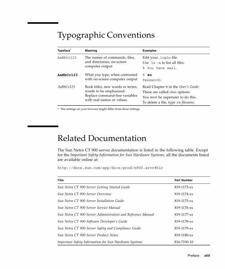
Typographic Conventions
Related DocumentationThe Sun Netra CT 900 server documentation is listed in the following table. Exceptfor the Important Safety Information for Sun Hardware Systems, all the documents listedare available online at:
http://docs.sun.com/app/docs/prod/n900.srvr#hic
Typeface*
* The settings on your browser might differ from these settings.
Meaning Examples
AaBbCc123 The names of commands, files,and directories; on-screencomputer output
Edit your.login file.Use ls -a to list all files.% You have mail.
AaBbCc123 What you type, when contrastedwith on-screen computer output
% su
Password:
AaBbCc123 Book titles, new words or terms,words to be emphasized.Replace command-line variableswith real names or values.
Read Chapter 6 in the User’s Guide.These are called class options.You must be superuser to do this.To delete a file, type rm filename.
Title Part Number
Sun Netra CT 900 Server Getting Started Guide 819-1173-xx
Sun Netra CT 900 Server Overview 819-1174-xx
Sun Netra CT 900 Server Installation Guide 819-1175-xx
Sun Netra CT 900 Server Service Manual 819-1176-xx
Sun Netra CT 900 Server Administration and Reference Manual 819-1177-xx
Sun Netra CT 900 Software Developer’s Guide 819-1178-xx
Sun Netra CT 900 Server Safety and Compliance Guide 819-1179-xx
Sun Netra CT 900 Server Product Notes 819-1180-xx
Important Safety Information for Sun Hardware Systems 816-7190-10
Preface xliii

Documentation, Support, and Training
Third-Party Web SitesSun is not responsible for the availability of third-party web sites mentioned in thisdocument. Sun does not endorse and is not responsible or liable for any content,advertising, products, or other materials that are available on or through such sitesor resources. Sun will not be responsible or liable for any actual or alleged damageor loss caused by or in connection with the use of or reliance on any such content,goods, or services that are available on or through such sites or resources.
Sun Welcomes Your CommentsSun is interested in improving its documentation and welcomes your comments andsuggestions. You can submit your comments by going to:
http://www.sun.com/hwdocs/feedback
Please include the title and part number of your document with your feedback:
Sun Netra CP3140 Switch Software Reference Manual, part number 819-3774-15
Sun Function URL Description
Documentation http://www.sun.com/documentation/ Download PDF and HTML documents,and order printed documents
Support andTraining
http://www.sun.com/supportraining/ Obtain technical support, downloadpatches, and learn about Sun courses
xliv Sun Netra CP3140 Switch Software Reference Manual • January 2010

Preface xlv
CHAPTER 1
FASTPATH Software
The FASTPATH software has two purposes:
■ To assist attached hardware in switching frames, based on layer 2, 3, or 4information contained in the frames.
■ To provide a complete device management portfolio to the network administrator.
The exact functionality provided by each switch on which the FASTPATH softwarebase runs varies depending upon the platform and requirements of the FASTPATHsoftware.
FASTPATH provides the network administrator with a set of comprehensivemanagement functions for managing both FASTPATH and the network. The networkadministrator has a choice of these easy-to-use management methods:
■ VT100 interface
■ Simple Network Management Protocol (SNMP)
Note – When configuring a device by use of a configuration file, the maximumnumber of configuration file command lines is 2000.
Each of the FASTPATH management methods enables the network administrator toconfigure, manage, and control FASTPATH locally or remotely using in-band orout-of-band mechanisms. Management is standards-based, with configurationparameters and a private management information base (MIB) providing control forfunctions not completely specified in the MIBs.
This chapter includes the following topics:
■ “FASTPATH On the Sun Netra CP3140 Switch” on page 2
■ “Sun Netra CP3140 Defaults” on page 2
■ “Protocol, RFC, and MIB Support” on page 3
1

FASTPATH On the Sun Netra CP3140SwitchThe FASTPATH software provides:
■ L2 switching with all the ports in VLAN 1
■ SNMP management
■ Telnet management
■ Serial management
Sun Netra CP3140 DefaultsThe Sun Netra CP3140 switches come configured with a default configuration. Thisconfiguration boots the board to Layer 2 switching. This configuration is very basicand should be updated for your environment. The default settings are:
■ Switch is configured with all ports enabled, set to auto-negotiate, MTU of 1518,and MAC switching mode in layer 2
■ All ports are in VLAN 1
■ DHCP client is enabled on the Out-of-band management port.
■ Telnet access enabled
■ SNMP read only community “public”
■ SNMP read write community “private”
Note – SNMPv3 traps are not supported on the Sun Netra CP3140 switches.
Multiple Spanning Tree (MSTP) is enabled by default. The Spanning Tree Protocol(STP) and Secure Shell (SSH) are not enabled in the default configuration.
Note – The Sun Netra CP3140 switch supports SSH for a secure CLI console butcannot generate its own keys. Keys must be generated on an external PC anduploaded to the Sun Netra CP3140 via TFTP. Once the keys are on the Sun NetraCP3140, SSH must be enabled to be used.
2 Sun Netra CP3140 Switch Software Reference Manual • January 2010

Protocol, RFC, and MIB SupportFASTPATH software provides support for the following protocols, RFCs, and MIBs.
Switching■ IEEE 802.3ac - VLAN Tagging
■ IEEE 802.3ad - Link Aggregation
■ IEEE 802.1S - Multiple Spanning Tree (MSTP)
■ IEEE 802.1W - Rapid Spanning Tree (RSTP)
■ IEEE 802.1D - Spanning Tree (STP)
■ GARP - Generic Attribute Registration Protocol
■ GMRP - Dynamic L2 Multicast Registration
■ GVRP - Dynamic VLAN Registration
■ IEEE 802.1Q - Virtual LANs with Port based VLANs
■ IEEE 802.1v - Protocol-based VLANs
■ IEEE 802.1p - Ethernet Priority with User Provisioning & Mapping
■ IEEE 802.1X - Port Based Authentication
■ IEEE 802.3x - Flow Control
Advanced Layer 2 Functionality■ Broadcast Storm Recovery
■ Double VLAN/vMAN Tagging (Q-in-Q)
■ IGMP Snooping
■ Independent VLAN Learning (IVL) support
■ IPv6 Classification APIs
■ Jumbo Ethernet Frames
■ Port Mirroring
■ Static MAC Filtering
System Facilities■ Event and Error Logging Facility
■ Run-time and Configuration Download Capability
■ PING Utility
Chapter 1 FASTPATH Software 3

■ XMODEM, YMODEM, & ZMODEM
■ RFC 768 - UDP
■ RFC 783 - TFTP
■ RFC 791 - IP
■ RFC 792 - ICMP
■ RFC 793 - TCP
■ RFC 826 - ARP
■ RFC 951 - BootP
■ RFC 1321 - Message Digest Algorithm
■ RFC 1534 - Interoperation between BootP and DHCP
■ RFC 2131 - DHCP Client/Server
■ RFC 2132 - DHCP Options and BootP Vendor Extensions
■ RFC 2865 - RADIUS Client
■ RFC 2866 - RADIUS Accounting
■ RFC 2868 - RADIUS Attributes for Tunnel Protocol
■ RFC 2869 - RADIUS Extensions
■ RFC2869bis- RADIUS Support for Extensible Authentication Protocol (EAP)
■ RFC 3580 - 802.lX RADIUS Usage Guidelines
Switching MIBs■ RFC 1213 - MIB-II
■ RFC 1493 - Bridge MIB
■ RFC 1643 - Ethernet-like MIB
■ RFC 2674 - VLAN MIB
■ RFC 2618 - RADIUS Authentication Client MIB
■ RFC 2620 - RADIUS Accounting MIB
■ RFC 2737 - Entity MIB version 2
■ RFC 2819 - RMON Groups 1,2,3, & 9
■ IEEE 802.1X (IEEE 802.1-PAE-MIB)
■ FASTPATH Enterprise MIB
Routing■ RFC 826 - Ethernet ARP
■ RFC 894 - Transmission of IP Datagrams over Ethernet Networks
4 Sun Netra CP3140 Switch Software Reference Manual • January 2010

■ RFC 896 - Congestion Control in IP/TCP Networks
■ RFC 1058 - RIP v1
■ RFC 1256 - ICMP Router Discovery Messages
■ RFC 1321 - Message Digest Algorithm
■ RFC 1519 - CIDR
■ RFC 1583 - OSPF v2
■ RFC 1723 - RIP v2
■ RFC 1765 - OSPF Database Overview
■ RFC 1812 - Requirements for IP Version 4 Routers
■ RFC 2082 - RIP-2 MD5 Authentication
■ RFC 2328 - OSPF v2 w/ Equal Cost Multipath
■ RFC 2338 - VRRP
■ RFC 2453 - RIP v2
■ RFC 3046 - DHCP/BootP Relay
■ RFC 3101 - OSPF “Not So Stubby Area” (NSSA) Option Route Redistributionacross RIP, OSPF, and BGP
Routing MIBS■ RFC 1724 - RIP v2 MIB Extension
■ RFC 1850 - OSPF MIB
■ RFC 2233 - The Interfaces Group MIN using SMI v2
■ RFC 2787 - VRRP MIB
Quality of Service (QOS)
Differentiated Services (DiffServ)■ RFC 2474 - Definition of Differentiated Services Field (DS Field) in the IPv4 and
IPv6 Headers
■ RFC 2475 - An Architecture for Differentiated Services
■ RFC 2597 - Assured Forwarding PHB Group
■ RFC 3246 – An Expedited Forwarding PHB (Per-Hop Behavior)
■ RFC 3260 – New Terminology and Clarifications for DiffServ
Chapter 1 FASTPATH Software 5

Access Control List (ACLs)
Permit/Deny actions for Inbound or Outbound traffic classification based on:
■ Type of Service (ToS) or Differentiated Services DSCP
■ Source IP Address
■ Destination IP Address
■ TCP/UDP Source Port
■ TCP/UDP Destination Port
■ IP Protocol Number
QoS MIBS■ RFC 3289 – Management Information Base for the Differentiated Services
Architecture
■ MIBs for full configuration of DiffServ, ACL and Bandwidth Provisioningfunctionality
Management■ RFC 854 – Telnet
■ RFC 855 – Telnet Option
■ RFC 1155 – SMI v1
■ RFC 1157 – SNMP
■ RFC 1212 – Concise MIB Definitions
■ RFC 1867 – HTML/2.0 Forms with file upload extensions
■ RFC 1901 – Community based SNMP v2
■ RFC 1905 – Protocol Operations for SNMP v2
■ RFC 1906 – Transport Mappings for SNMP v2
■ RFC 1907 – Management Information Base for SNMP v2
■ RFC 1908 – Coexistence between SNMP v1 and SNMP v2
■ RFC 2068 – HTTP/1.1 protocol as updated by draft-ietf-http-v11-rev-03
■ RFC 2271 – SNMP Framework MIB
■ RFC 2295 – Transparent Content Negotiation
■ RFC 2296 – Remote Variant Selection; RSVA/1.0 State Management “cookies” –draft-ietf-http-state-mgmt-05
■ RFC 2570 – Introduction to SNMP v3
■ RFC 2571 – Architecture for Describing SNMP Management Frameworks
6 Sun Netra CP3140 Switch Software Reference Manual • January 2010

■ RFC 2572 – Message Processing and Dispatching for SNMP
■ RFC 2573 – SNMP v3 Applications
■ RFC 2574 – User Based Security Model for SNMP v3
■ RFC 2575 – View based Access Control Model for SNMP
■ RFC 2576 0 Coexistence between SNMP v1, V2, and v3
■ RFC 2578 – SMI v2
■ RFC 2579 – Textual Conventions for SMI v2
■ RFC 2580 – Conformance statements for SMI v2 Configurable ManagementVLAN
■ SSL 3.0 and TLS 1.0
■ -RFC 2246 - The TLS Protocol, Version 1.0
■ -RFC 2818 – HTTP over TLS
■ RFC 2346 – AES Ciphersuites for Transport Layer Security
■ SSH 1.5 and 2.0
■ -Draft-ietf-secsh-transport-16 – SSH Transport Layer Protocol
■ -Draft-ietf-secsh-userauth-17 – SSH Authentication Protocol
■ -Draft-ietf-secsh-connect-14 – SSH Protocol Architecture
■ -Draft-ietf-secsh-publickeyfile-03 – SECSH Public Key File Format
■ -Draft-ietf-sech-dh-group-exhange-04 – Diffie-Hellman Group Exchange for theSSH Transport Layer Protocol
■ HTML 4.0 Specification – December, 1997
■ Java and Java Script 1.3
Other■ Industry standard CLI
■ scripting capability
■ command completion
■ context sensitive help
■ User password encryption
■ Multi-session Telnet Server
Chapter 1 FASTPATH Software 7

8 Sun Netra CP3140 Switch Software Reference Manual • January 2010

CHAPTER 2
Command Structure
The command-line interface (CLI) syntax, conventions, and terminology aredescribed in this chapter. Each CLI command referenced in this document isillustrated using the structure outlined below.
This chapter includes the following topics:
■ “Format for CLI Commands” on page 9
■ “Comments” on page 12
■ “Special Characters” on page 13
Format for CLI CommandsSome commands, such as show inventory or clear vlan, do not requireparameters. Other commands, such as network parms, have parameters for whichyou must supply a value. Parameters are positional—you must type the values inthe correct order. Optional parameters will follow required parameters. Followingare two examples.
In the preceding example, <ipaddr> and <netmask> are the required values for thecommand, and [gateway] is the optional value for the command.
In the second example, <loc> is the required parameter for the command.
network parms <ipaddr> <netmask> [gateway]
snmp-server location <loc>
9
Command ConventionsThe following conventions apply to the command name:
■ The command name is displayed in this document in monospace font and mustbe typed exactly as shown.
■ Once you have entered enough letters of a command name to uniquely identifythe command, pressing the spacebar or Tab key causes the system to complete theword.
■ Pressing Ctrl-Z returns you to the root-level command prompt.
Parameter ConventionsThe following conventions apply to parameters:
■ Parameters are order dependent.
■ Variables are displayed in this document in italic font, and must be replaced witha name or number.
■ To use spaces as part of a name parameter, enclose it in double quotes. Forexample, the expression “System Name with Spaces” forces the system to acceptthe spaces.
■ Parameters might be mandatory values, optional values, choices, or acombination:
■ <parameter>. The <> (angle brackets) indicate that you must enter amandatory parameter.
■ [parameter]. The [] brackets indicate that you may enter an optional parameterin place of the brackets and text inside them.
■ choice1 | choice2. The | (pipe) indicates that you should enter only one of theparameters.
■ The {} (braces) indicate that you must choose a parameter from the list ofchoices.
Values of Common ParametersThe following conventions apply to the values of the common parameters:
ipaddr
This parameter is a valid IP address. You can enter an IP address in the followingformats:
10 Sun Netra CP3140 Switch Software Reference Manual • January 2010

■ a (32 bits)
■ a.b (8.24 bits)
■ a.b.c (8.8.16 bits)
■ a.b.c.d (8.8.8.8)
In addition to these formats, decimal, hexadecimal, and octal formats are supportedthrough the following input formats (where n is any valid hexadecimal, octal, ordecimal number):
■ 0xn (CLI assumes hexadecimal format)
■ 0n (CLI assumes octal format with leading zeros)
■ n (CLI assumes decimal format)
macaddr
The MAC address format is six hexadecimal numbers separated by colons — forexample, 00:06:29:32:81:40.
areaid
You can enter Area IDs in dotted-decimal notation (for example, 0.0.0.1). An area IDof 0.0.0.0 is reserved for the backbone. Area IDs have the same form as IP addresses,but are distinct from IP addresses. You can use the IP network number of the sub-netted network for the area ID.
routerid
You must enter the value of <router id> in 4-digit, dotted-decimal notation (forexample, 0.0.0.1). A router ID of 0.0.0.0 is invalid.
slot/port
Enter a valid slot and port number separated by forward slashes. For example, 0/1represents slot number 0 and port number 1.
logical slot/port
The logical slot and port number value is applicable in the case of a port-channel(LAG). The operator can use the logical slot/port to configure the port-channel.
Chapter 2 Command Structure 11
Character Strings
Use double quotation marks to identify character strings—for example, “SystemName with Spaces”. An empty string (“”) is not valid.
Network Addresses
Network addresses define a link to a remote host, workstation, or network. Networkaddresses use the syntax shown in TABLE 2-1.
Command Completion
Command completion finishes spelling the command when you have typed enoughletters of a command to uniquely identify the command word. You can execute thecommand by pressing the Enter key (command abbreviation) or you can completethe command word by pressing the Tab or spacebar keys (command completion).
The value “Er” designates that the requested value was not internally accessible.This should not happen and indicates that the software is not handling this instancecorrectly.
The value of “-----” designates that the value is unknown.
CommentsThe CLI enables the user to type single-line annotations at the command prompt foruse when writing test or configuration scripts and for better readability. Theexclamation point (!) character flags the beginning of a comment. The comment flagcharacter can begin a word anywhere on the command line and all input followingthis character is ignored. Any command line that begins with the character ! isrecognized as a comment line and ignored by the parser.
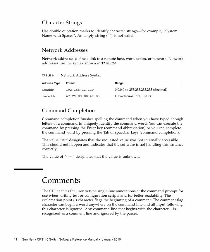
TABLE 2-1 Network Address Syntax
Address Type Format Range
ipaddr 192.165.11.110 0.0.0.0 to 255.255.255.255 (decimal)
macaddr A7:C9:89:DD:A9:B3 Hexadecimal digit pairs
12 Sun Netra CP3140 Switch Software Reference Manual • January 2010

Some examples of comments are provided in the following code.
Special CharactersCertain key combinations speed up use of the CLI. They are listed in this section.Help for the CLI is available by typing HELP.
! Script file for displaying the ip interface! Display information about interfacesshow ip interface 0/1 !Displays the information about the first interface! Display information about the next interfaceshow ip interface 0/2! End of the script file
TABLE 2-2 Special Characters
Key Combination Meaning
Del, Backspace Delete previous character
Ctrl-A Go to beginning of line
Ctrl-E Go to end of line
Ctrl-F Go forward one character
Ctrl-B Go backward one character
Ctrl-D Delete current character
Ctrl-H Display command history or retrieve a command
Ctrl-U, X Delete to beginning of line
Ctrl-K Delete to end of line
Ctrl-W Delete previous word
Ctrl-T Transpose previous character
Ctrl-P Go to previous line in history buffer
Ctrl-N Go to next line in history buffer
Ctrl-Z Return to root command prompt
Tab, spacebar Command-line completion
Exit Go to next lower command prompt
Chapter 2 Command Structure 13

14 Sun Netra CP3140 Switch Software Reference Manual • January 2010

CHAPTER 3
Quick Startup
This chapter describes the procedures that enable you to quickly become acquaintedwith the FASTPATH software.
This chapter includes the following topics:
■ “Starting the Switch” on page 15
■ “System Info and System Setup” on page 16
Starting the Switch1. Read the Sun Netra CT 900 Server Installation Guide for the connectivity
procedure.
In-band connectivity enables access to the FASTPATH software locally or from aremote workstation. The device must be configured with IP information (IPaddress, subnet mask, and default gateway).
2. Turn the power on to the server.
Refer to the Sun Netra CT 900 Server Installation Guide for more information.
3. Allow the device to load the software until the login prompt appears.
The device initial state is called the default mode.
4. When the prompt asks for operator login, execute these steps:
a. Type the word admin in the login area.
Since a number of the Quick Setup commands require administrator accountrights, you should log in to an administrator account. Do not enter apassword because there is no password in the default mode.
15
b. Press Enter twice.
The CLI User EXEC prompt is displayed.
At this point, you have several options:
■ Type enable to switch to the Privileged EXEC mode from User EXEC.
■ Type configure to switch to the Global Config mode from Privileged EXEC.
■ Type exit to return to the previous mode.
System Info and System SetupThe tables in this section include the following topics:
■ Displaying the Software Version Information—page 16
■ Displaying the Physical Port Data—page 17
■ Managing the User Accounts—page 17
■ Displaying IP Address Information—page 19
■ Uploading IP Address Information From Switch to Out-of-Band PC(XMODEM)—page 20
■ Downloading IP Address Information From Out-of-Band PC to Switch (OnlyXMODEM)—page 20
■ Downloading IP Address Information from TFTP Server—page 21
■ Factory Defaults for IP Address Information—page 21
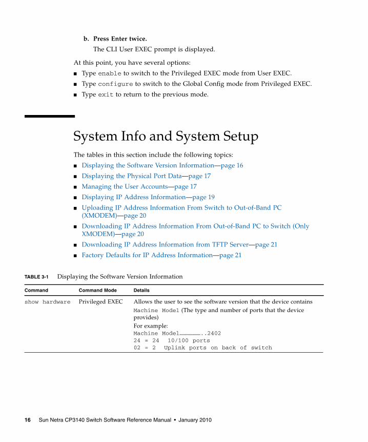
TABLE 3-1 Displaying the Software Version Information
Command Command Mode Details
show hardware Privileged EXEC Allows the user to see the software version that the device containsMachine Model (The type and number of ports that the deviceprovides)For example:Machine Model………………..240224 = 24 10/100 ports02 = 2 Uplink ports on back of switch
16 Sun Netra CP3140 Switch Software Reference Manual • January 2010

TABLE 3-2 Displaying the Physical Port Data
Command Command Mode Details
show port all Privileged EXEC Displays the ports:• Slot/port• Type – Indicates if the port is a special type of port• Admin Mode – Selects the Port Control Administration State• Physical Mode – Selects the desired port speed and duplex mode• Physical Status – Indicates the port speed and duplex mode• Link Status – Indicates whether the link is up or down• Link Trap – Determines whether or not to send a trap when link
status changes• LACP Mode – Displays whether LACP is enabled or disabled on this
port
TABLE 3-3 Managing the User Accounts
Command Command Mode Details
show users Privileged EXEC Displays all of the users that are allowed to access the switch:• Access Mode – Shows whether the user is able to change
parameters on the switch (read/write) or is only able to viewthem (read only).
As a factory default, the admin user has read/write access and theguest user has read only access. There can only be one read/writeuser and up to five read only users.
showloginsession
User EXEC Displays all of the login session information.
Chapter 3 Quick Startup 17

Managing IP AddressesTo view the network parameters, the operator can access the device by the followingmethods.
■ Simple Network Management Protocol (SNMP)
■ Telnet
Note – You should runcopy system:running-config nvram:startup-configafter configuring the network parameters so that the configurations are not lost.Refer to TABLE 3-8 on page 21 for more information.
users passwd[username]
Global Config Allows the user to set passwords or change passwords needed tolog in.
A prompt appears after the command is entered requesting theuser’s old password. In the absence of an old password, leave thearea blank. The operator must press Enter to execute the command.
The system prompts the user for a new password and then displaysa prompt to confirm the new password. If the new password andthe confirmed password match, a message is displayed.
User password’s should not be more than eight characters in length.
copy system:running-config
nvram: startup-config
Privileged EXEC Saves passwords and all other changes to the device.
If you do not save the configuration with this command, allconfigurations are lost when a power cycle is performed on theswitch or when the switch is reset.
logout User EXEC andPrivileged EXEC
Logs the user out of the switch.
TABLE 3-3 Managing the User Accounts (Continued)
Command Command Mode Details
18 Sun Netra CP3140 Switch Software Reference Manual • January 2010
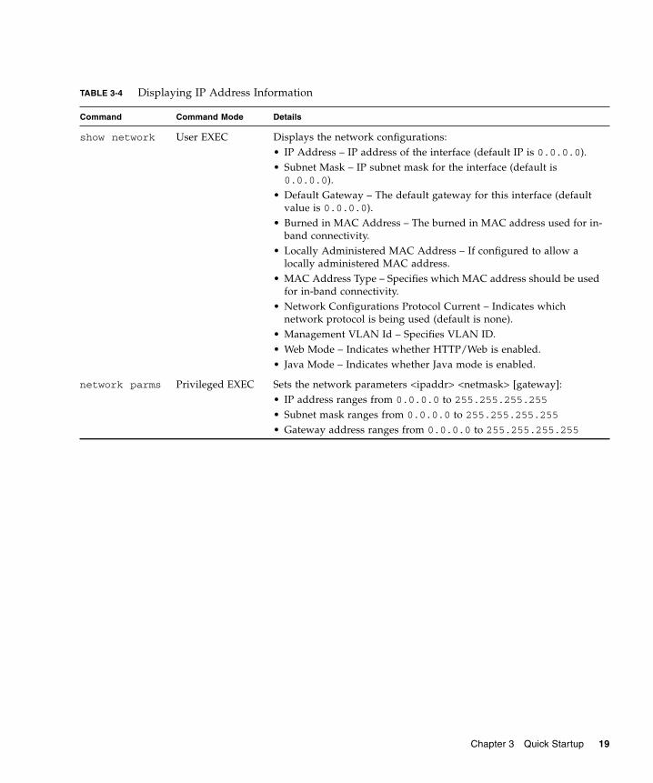
TABLE 3-4 Displaying IP Address Information
Command Command Mode Details
show network User EXEC Displays the network configurations:• IP Address – IP address of the interface (default IP is 0.0.0.0).• Subnet Mask – IP subnet mask for the interface (default is0.0.0.0).
• Default Gateway – The default gateway for this interface (defaultvalue is 0.0.0.0).
• Burned in MAC Address – The burned in MAC address used for in-band connectivity.
• Locally Administered MAC Address – If configured to allow alocally administered MAC address.
• MAC Address Type – Specifies which MAC address should be usedfor in-band connectivity.
• Network Configurations Protocol Current – Indicates whichnetwork protocol is being used (default is none).
• Management VLAN Id – Specifies VLAN ID.• Web Mode – Indicates whether HTTP/Web is enabled.• Java Mode – Indicates whether Java mode is enabled.
network parms Privileged EXEC Sets the network parameters <ipaddr> <netmask> [gateway]:• IP address ranges from 0.0.0.0 to 255.255.255.255
• Subnet mask ranges from 0.0.0.0 to 255.255.255.255
• Gateway address ranges from 0.0.0.0 to 255.255.255.255
Chapter 3 Quick Startup 19

Before starting a Trivial File Transfer Protocol (TFTP) server download, the operatormust complete the Quick Startup for the IP address.
TABLE 3-5 Uploading IP Address Information From Switch to Out-of-Band PC (XMODEM)
Command Details
copy {nvram:startup-config |nvram:errorlog | nvram:msglog |nvram: traplog} [url]
The types are:• Config – Configuration file• Errorlog – Error log• System trace – System trace• Traplog – Trap log
The URL must be specified as:Xmodem:filepath/filename
This starts the upload, displays the mode of uploading andthe type of upload it is, and confirms the upload is takingplace.For example:If the user is using HyperTerminal, the user must specifywhere the file will be received by the PC.
TABLE 3-6 Downloading IP Address Information From Out-of-Band PC to Switch (Only XMODEM)
Command Details
copy [url] {nvram:startup-config |system:image}
Sets the destination (download) data type to be an image(system:image) or a configuration file(nvram:startup-config).
The URL must be specified as:Xmodem:filepath/filename
For example:If the user is using HyperTerminal, the user must specifywhich file is to be sent to the switch.
The switch restarts automatically once the code has beendownloaded.
20 Sun Netra CP3140 Switch Software Reference Manual • January 2010
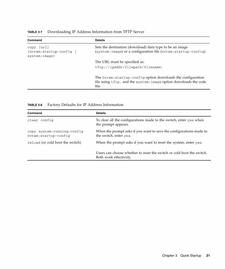
TABLE 3-7 Downloading IP Address Information from TFTP Server
Command Details
copy [url]{nvram:startup-config |system:image}
Sets the destination (download) data type to be an image(system:image) or a configuration file (nvram:startup-config).
The URL must be specified as:tftp://ipAddr/filepath/filename.
The nvram:startup-config option downloads the configurationfile using tftp, and the system:image option downloads the codefile.
TABLE 3-8 Factory Defaults for IP Address Information
Command Details
clear config To clear all the configurations made to the switch, enter yes whenthe prompt appears.
copy system:running-confignvram:startup-config
When the prompt asks if you want to save the configurations made tothe switch, enter yes.
reload (or cold boot the switch) When the prompt asks if you want to reset the system, enter yes.
Users can choose whether to reset the switch or cold boot the switch.Both work effectively.
Chapter 3 Quick Startup 21

22 Sun Netra CP3140 Switch Software Reference Manual • January 2010

CHAPTER 4
Mode-Based Command-LineInterface
The command-line interface (CLI) groups all the commands in appropriate modesaccording to the nature of the commands. Each of the command modes supportsspecific FASTPATH software commands.
This chapter includes the following topics:
■ “Mode-Based Topology” on page 25
■ “Mode-Based Command Hierarchy” on page 26
■ “Flow of Operation” on page 30
■ ““No” Form of a Command” on page 31
TABLE 4-1 lists the command modes, the prompts visible in each mode, and the exitmethod from that mode.
TABLE 4-1 CLI Command Modes
Command Mode Access Method Prompt Exit or Access Previous Mode
User Exec This is the first level of accessfor performing basic tasks andlisting system information.
Switch> Enter logout command
Privileged Exec From the User Exec mode,enter the enable command.
Switch# Type exit or press Ctrl-Z toexit to the User Exec mode.
VLAN From the Privileged Execmode, enter the vlandatabase command.
Switch(Vlan)# Type exit to exit to thePrivileged Exec mode, or pressCtrl-Z to switch to the UserExec mode.
Global Config From the Privileged Execmode, enter the configurecommand.
Switch(Config)# Type exit to exit to thePrivileged Exec mode, or pressCtrl-Z to switch to the UserExec mode.
23
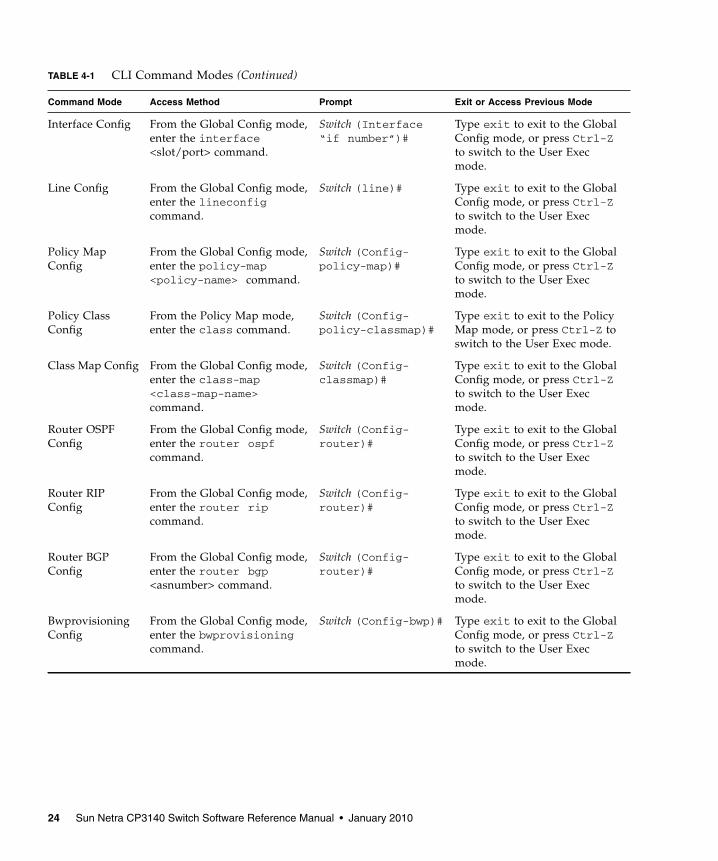
Interface Config From the Global Config mode,enter the interface<slot/port> command.
Switch (Interface“if number”)#
Type exit to exit to the GlobalConfig mode, or press Ctrl-Zto switch to the User Execmode.
Line Config From the Global Config mode,enter the lineconfigcommand.
Switch (line)# Type exit to exit to the GlobalConfig mode, or press Ctrl-Zto switch to the User Execmode.
Policy MapConfig
From the Global Config mode,enter the policy-map<policy-name> command.
Switch (Config-policy-map)#
Type exit to exit to the GlobalConfig mode, or press Ctrl-Zto switch to the User Execmode.
Policy ClassConfig
From the Policy Map mode,enter the class command.
Switch (Config-policy-classmap)#
Type exit to exit to the PolicyMap mode, or press Ctrl-Z toswitch to the User Exec mode.
Class Map Config From the Global Config mode,enter the class-map<class-map-name>command.
Switch (Config-classmap)#
Type exit to exit to the GlobalConfig mode, or press Ctrl-Zto switch to the User Execmode.
Router OSPFConfig
From the Global Config mode,enter the router ospfcommand.
Switch (Config-router)#
Type exit to exit to the GlobalConfig mode, or press Ctrl-Zto switch to the User Execmode.
Router RIPConfig
From the Global Config mode,enter the router ripcommand.
Switch (Config-router)#
Type exit to exit to the GlobalConfig mode, or press Ctrl-Zto switch to the User Execmode.
Router BGPConfig
From the Global Config mode,enter the router bgp<asnumber> command.
Switch (Config-router)#
Type exit to exit to the GlobalConfig mode, or press Ctrl-Zto switch to the User Execmode.
BwprovisioningConfig
From the Global Config mode,enter the bwprovisioningcommand.
Switch (Config-bwp)# Type exit to exit to the GlobalConfig mode, or press Ctrl-Zto switch to the User Execmode.
TABLE 4-1 CLI Command Modes (Continued)
Command Mode Access Method Prompt Exit or Access Previous Mode
24 Sun Netra CP3140 Switch Software Reference Manual • January 2010

Mode-Based TopologyThe CLI tree is built on a mode concept in which the commands are availableaccording to the interface. Some of the modes in the mode-based CLI are depicted inFIGURE 4-1.
Note – The User Exec commands are also accessible in the Privileged Exec Mode.
Note – Access to all commands in the Privileged Exec mode and below is restrictedthrough a password.
Bwprovisioning-TrafficclassConfig
From the Bwprovisioningmode, enter the traffic-class command.
Switch (Config-bwp-trafficclass)#
Type exit to exit to theBwprovisioning Config mode,or press Ctrl-Z to switch to theUser Exec mode.
Bwprovisioning-bwallocationConfig
From the Bwprovisioningmode, enter thebwallocation command.
Switch (Config-bwp-bwallocation)#
Type exit to exit to theBwprovisioning mode. Toreturn to the User Exec mode,enter Ctrl-Z.
DHCP PoolConfig
From the Global Config mode,enter the ip dhcp pool<pool-name> command.
Switch (Config-dhcp-pool)#
Type exit to exit to the GlobalConfig mode, or press Ctrl-Zto switch to the User Execmode.
TABLE 4-1 CLI Command Modes (Continued)
Command Mode Access Method Prompt Exit or Access Previous Mode
Chapter 4 Mode-Based Command-Line Interface 25

FIGURE 4-1 Mode-based CLI
Class Map Line Config Router OSPFConfig
Root
User Exec
Enable
Global Config
No
Yes
PasswdCorrect
Return to theExec prompt
?
Privileged Exec
VLAN
Interface Config
Policy MapBwprovisioning DHCP PoolConfig
Router BGPConfig
Policy ClassRouter RIP
Config
StackingConfigBwp
bwallocationBwp
traffic class
Return to theUser prompt
26 Sun Netra CP3140 Switch Software Reference Manual • January 2010

Mode-Based Command HierarchyThe CLI is divided into modes. The commands in one mode are not available untilthe operator switches to that particular mode, with the exception of the User Execmode commands. The User Exec mode commands can also be executed in thePrivileged Exec mode.
The commands available to the operator at any time depend upon the mode.Entering a question mark (?) at the CLI prompt displays a list of the currentlyavailable commands and descriptions of the commands.
The CLI provides the following modes.
User Exec ModeWhen the operator logs in to the CLI, the User Exec mode is the initial mode. TheUser Exec mode contains a limited set of commands. The command prompt shownat this level is $>
Privileged Exec ModeTo have access to the full suite of commands, the operator must enter the PrivilegedExec mode. The Privileged Exec mode requires password authentication. FromPrivileged Exec mode, the operator can issue any Exec command, enter the VLANmode or enter the Global Config mode. The command prompt shown at this level is$#
VLAN ModeThis mode groups all the commands pertaining to VLANs. The command promptshown at this level is $(VLAN)#
Chapter 4 Mode-Based Command-Line Interface 27
Global Config ModeThis mode permits the operator to make modifications to the running configuration.General setup commands are grouped in this mode. From the Global Config mode,the operator can enter the System Config mode, the Physical Port Config mode, theInterface Config mode, or the protocol-specific modes specified in the followingsections. The command prompt at this level is $(Config)#
From the Global Config mode, the operator can enter the following configurationmodes.
Interface Config Mode
Many features are enabled for a particular interface. The Interface commands enableor modify the operation of an interface.
In this mode, a physical port is set up for a specific logical connection operation. TheInterface Config mode provides access to the router interface configurationcommands. The command prompt at this level is $(Interface <slot/port>)#
The resulting prompt for the interface configuration command entered in the GlobalConfiguration mode is $(Config)# interface 2/1 and $(Interface 2/1)#+
Line Config Mode
This mode allows the operator to configure the console interface. The operator canconfigure the interface from the directly connected console or the virtual terminalused with Telnet. The command prompt at this level is $(Line)#
Policy Map Mode
Use the policy-map <policy-name> command to access the QoS policy mapconfiguration mode to configure the QoS policy map.
$(Config)# policy map <policy-name>
$(Config-policy-map)#
Policy Class Mode
Use the class <class-name> command to access the QoS policy-classmap mode toattach or remove a diffserv class to a policy and to configure the QoS policy class.
28 Sun Netra CP3140 Switch Software Reference Manual • January 2010
$(Config policy-map)# class <class-name>
$(Config-policy-classmap)#
Class Map Mode
This mode consists of class creation, deletion, and matching commands. The classmatch commands specify layer 2, layer 3, and general match criteria. Use theclass-map <class-map-name> commands to access the QoS class mapconfiguration mode to configure QoS class maps.
$(Config)# class-map <class-map-name>
$(Config class-map)#
Router OSPF Config Mode
In this mode, the operator is allowed to access the router OSPF configurationcommands. The command prompt at this level is:
$(Config)# router ospf
$(Config router)#
Router RIP Config Mode
In this mode, the operator is allowed to access the router RIP configurationcommands. The command prompt at this level is:
$(Config)# router rip
$(Config router)#
Router BGP Config Mode
In this mode, the operator is allowed to access the router BGP-4 configurationcommands. The command prompt at this level is:
$(Config)# router bgp <1-65535>
$(Config-routerbgp)#
Chapter 4 Mode-Based Command-Line Interface 29
Bwprovisioning Config Mode
Use the bwprovisioning command to access the Bandwidth provisioning Configmode to configure bandwidth provisioning.
$(Config)# bwprovisioning
$(Config-bwp)#
Bwprovisioning Trafficclass Mode
Use the traffic-class command to access the Bandwidth provisioning Configmode to configure bandwidth traffic class.
$(Config bwp)# traffic-class
$(Config-bwp-trafficclass)#
Bwprovisioning bwallocation Mode
Use the bwallocation command to access the Bandwidth provisioning Configmode to configure bandwidth allocation.
$(Config bwp)# bwallocation
$(Config bwp-bwallocation)#
DHCP Pool Config Mode
Use the ip dhcp pool <pool-name> command to access the DHCP Pool Configmode.
$(Config)# ip dhcp pool <pool-name>
$(Config-dhcp-pool)#
Flow of OperationThis section captures the flow of operation for the CLI.
1. The operator logs in to the CLI session and enters the User Exec mode. In theUser Exec mode, the $(exec)> prompt is displayed on the screen.
30 Sun Netra CP3140 Switch Software Reference Manual • January 2010
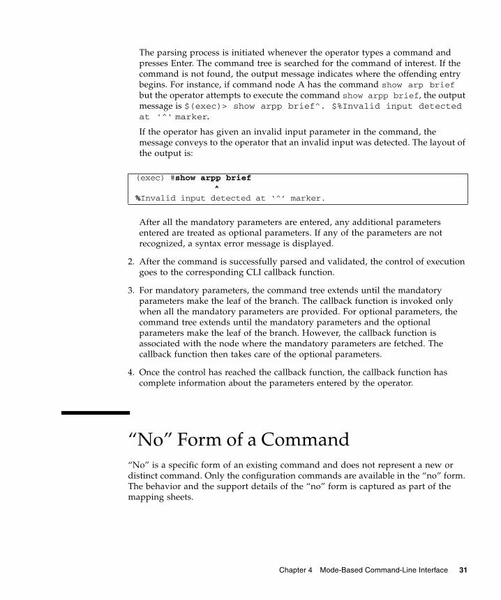
The parsing process is initiated whenever the operator types a command andpresses Enter. The command tree is searched for the command of interest. If thecommand is not found, the output message indicates where the offending entrybegins. For instance, if command node A has the command show arp briefbut the operator attempts to execute the command show arpp brief, the outputmessage is $(exec)> show arpp brief^. $%Invalid input detectedat '^' marker.
If the operator has given an invalid input parameter in the command, themessage conveys to the operator that an invalid input was detected. The layout ofthe output is:
After all the mandatory parameters are entered, any additional parametersentered are treated as optional parameters. If any of the parameters are notrecognized, a syntax error message is displayed.
2. After the command is successfully parsed and validated, the control of executiongoes to the corresponding CLI callback function.
3. For mandatory parameters, the command tree extends until the mandatoryparameters make the leaf of the branch. The callback function is invoked onlywhen all the mandatory parameters are provided. For optional parameters, thecommand tree extends until the mandatory parameters and the optionalparameters make the leaf of the branch. However, the callback function isassociated with the node where the mandatory parameters are fetched. Thecallback function then takes care of the optional parameters.
4. Once the control has reached the callback function, the callback function hascomplete information about the parameters entered by the operator.
“No” Form of a Command“No” is a specific form of an existing command and does not represent a new ordistinct command. Only the configuration commands are available in the “no” form.The behavior and the support details of the “no” form is captured as part of themapping sheets.
(exec) #show arpp brief^
%Invalid input detected at ‘^’ marker.
Chapter 4 Mode-Based Command-Line Interface 31

Support for “No” FormAlmost every configuration command has a “no” form. In general, use the “no”form to reverse the action of a command or reset a value back to the default. Forexample, the no shutdown interface configuration command reverses theshutdown of an interface. Use the command without the keyword no to re-enable adisabled feature or to enable a feature that is disabled by default.
Behavior of Command Help (?)The “no” form is treated as a specific form of an existing command and does notrepresent a new or distinct command. The behavior of the “?” and the help text arethe same for the “no” form:
■ The help message is the same for all forms of the command. The help string mightbe augmented with details about the “no” form behavior.
■ For the (no interface?) and (no inte?) cases, the help options displayed areidentical to the case when the “no” token is not specified, as in (interface?) and(inte?).
32 Sun Netra CP3140 Switch Software Reference Manual • January 2010

CHAPTER 5
Switching Commands
This chapter provides a detailed explanation of the Switching commands. It includesthe following configuration types:
■ “System Information and Statistics Commands” on page 34
■ “System Management Commands” on page 49
■ “SNMP Community Commands” on page 59
■ “Management VLAN Command” on page 69
■ “System Configuration Commands” on page 70
■ “Virtual LAN (VLAN) Commands” on page 81
■ “System Utility Commands” on page 93
■ “User Account Commands” on page 97
■ “Port Based Network Access Control (IEEE 802.1X) Commands” on page 101
■ “Remote Authentication Dial In User Service (RADIUS) Commands” on page 117
■ “Secure Shell (SSH) Commands” on page 123
■ “Hypertext Transfer Protocol (HTTP) Commands” on page 124
■ “DHCP Server Commands” on page 127
■ “Double VLAN Commands” on page 142
■ “Provisioning (IEEE 802.1p) Commands” on page 146
■ “GARP Commands” on page 147
■ “GARP VLAN Registration Protocol (GVRP) Commands” on page 152
■ “GARP Multicast Registration Protocol (GMRP) Commands” on page 155
■ “Internet Group Management Protocol (IGMP) Commands” on page 158
■ “Spanning Tree (STP) Commands” on page 163
■ “Layer 2 Failover Commands” on page 179
■ “Link Aggregation (LAG)/Port-Channel (802.3AD) Commands” on page 180
33

System Information and StatisticsCommandsThis section provides a detailed explanation of the FASTPATH software platformcommands. The commands are divided into four functional groups:
■ Show commands display switch settings, statistics, and other information.
■ Configuration commands configure features and options of the switch. For everyconfiguration command, there is a show command that displays the configurationsetting.
■ Copy commands transfer or save configuration and informational files to andfrom the switch.
■ Clear commands clear some or all of the settings to factory defaults.
show arp switch
This command displays connectivity between the switch and other devices. TheAddress Resolution Protocol (ARP) cache identifies the MAC addresses of the IPstations communicating with the switch.
■ Format – show arp switch
■ Mode – Privileged EXEC
TABLE 5-1 Entry Definitions for show arp switch
Entry Definition
MAC Address A unicast MAC address for which the switch has forwarding and/orfiltering information. The format is six two-digit hexadecimalnumbers that are separated by colons—for example,01:23:45:67:89:AB
IP Address The IP address assigned to each interface.
slot/port Valid slot and port number separated by forward slashes.
34 Sun Netra CP3140 Switch Software Reference Manual • January 2010

show eventlog
This command displays the event log, which contains error messages from thesystem. The event log is not cleared on a system reset.
■ Format – show eventlog
■ Mode – Privileged EXEC
Note – Event log information is retained across a switch reset.
show hardware
This command displays inventory information for the switch.
■ Format – show hardware
■ Mode – Privileged EXEC
TABLE 5-2 Entry Definitions for show eventlog
Entry Definition
File The file in which the event originated.
Line The line number of the event
Task Id The task ID of the event
Code The event code
Time The time this event occurred
TABLE 5-3 Entry Definitions for show hardware
Entry Definition
Switch Description Text used to identify the product name of this switch
Machine Type The machine model as defined by the Vital Product Data
Machine Model The machine model as defined by the Vital Product Data
Serial Number The unique box serial number for this switch
FRU Number The field-replaceable unit number
Part Number Manufacturing part number
Maintenance Level Indicates hardware changes that are significant to software
Chapter 5 Switching Commands 35

show interface
This command displays a summary of statistics for a specific port or a count of allCPU traffic based upon the argument.
■ Format – show interface {<slot/port> | switchport}
■ Mode – Privileged EXEC
The display parameters, when the argument is <slot/port>, are as follows.
Manufacturer Manufacturer descriptor field
Burned in MACAddress
Universally assigned network address
Software Version The release.version.revision number of the code currently running onthe switch
Operating System The operating system currently running on the switch
Network ProcessingElement
The type of the processor microcode
Additional Packages This displays the additional packages that are incorporated into thissystem, such as FASTPATH BGP-4, or FASTPATH Multicast
TABLE 5-4 Entry Definitions for show interface for slot/port Argument
Entry Definition
Packets ReceivedWithout Error
The total number of packets (including broadcast packets andmulticast packets) received by the processor.
Packets ReceivedWith Error
The number of inbound packets that contained errors preventingthem from being deliverable to a higher-layer protocol.
Broadcast PacketsReceived
The total number of packets received that were directed to thebroadcast address. This does not include multicast packets.
Packets TransmittedWithout Error
The total number of packets transmitted out of the interface.
TABLE 5-3 Entry Definitions for show hardware
Entry Definition
36 Sun Netra CP3140 Switch Software Reference Manual • January 2010

The display parameters, when the argument is switchport, are as follows.
Transmit PacketsErrors
The number of outbound packets that could not be transmitted becauseof errors.
Collisions Frames The best estimate of the total number of collisions on this Ethernetsegment.
Time Since CountersLast Cleared
The elapsed time, in days, hours, minutes, and seconds since thestatistics for this port were last cleared.
TABLE 5-5 Entry Definitions for show interface for switchport Argument
Entry Definition
Packets ReceivedWithout Error
The total number of packets (including broadcast packets andmulticast packets) received by the processor.
Broadcast PacketsReceived
The total number of packets received that were directed to thebroadcast address. This does not include multicast packets.
Packets ReceivedWith Error
The number of inbound packets that contained errors preventingthem from being deliverable to a higher-layer protocol.
Packets TransmittedWithout Error
The total number of packets transmitted out of the interface.
Broadcast PacketsTransmitted
The total number of packets that higher-level protocols requested tobe transmitted to the broadcast address, including those that werediscarded or not sent.
Transmit Packet Errors The number of outbound packets that could not be transmittedbecause of errors.
Address EntriesCurrently In Use
The total number of Forwarding Database Address Table entries nowactive on the switch, including learned and static entries.
VLAN EntriesCurrently In Use
The number of VLAN entries presently occupying the VLAN table.
Time Since CountersLast Cleared
The elapsed time, in days, hours, minutes, and seconds, since thestatistics for this switch were last cleared.
TABLE 5-4 Entry Definitions for show interface for slot/port Argument
Entry Definition
Chapter 5 Switching Commands 37

show interface ethernet
This command displays detailed statistics for a specific port or for all CPU trafficbased upon the argument.
■ Format – show interface ethernet {<slot/port> | switchport}
■ Mode – Privileged EXEC
The display parameters, when the argument is '<slot/port>', are as follows.
TABLE 5-6 Entry Definitions for show interface ethernet for slot/port Argument
First-Level Entry Second-Level Entry Definition
Packets Received Octets Received The total number of octets of data (including those inbad packets) received on the network (excludingframing bits but including Frame Check Sequence(FCS) octets). This object can be used as a reasonableestimate of Ethernet utilization. If greater precision isdesired, the etherStatsPkts and etherStatsOctetsobjects should be sampled before and after a commoninterval. The result of this equation is the valueUtilization which is the percent utilization of theEthernet segment on a scale of 0 to 100 percent.
Packets Received < 64 Octets The total number of packets (including bad packets)received that were < 64 octets in length (excludingframing bits but including FCS octets).
Packets Received 64 Octets The total number of packets (including bad packets)received that were 64 octets in length (excludingframing bits but including FCS octets).
Packets Received 65-127 Octets The total number of packets (including bad packets)received that were between 65 and 127 octets in lengthinclusive (excluding framing bits but including FCSoctets).
Packets Received 128-255 Octets The total number of packets (including bad packets)received that were between 128 and 255 octets inlength inclusive (excluding framing bits but includingFCS octets).
Packets Received 256-511 Octets The total number of packets (including bad packets)received that were between 256 and 511 octets inlength inclusive (excluding framing bits butincluding FCS octets).
Packets Received 512-1023 Octets The total number of packets (including bad packets)received that were between 512 and 1023 octets inlength inclusive (excluding framing bits but includingFCS octets).
38 Sun Netra CP3140 Switch Software Reference Manual • January 2010
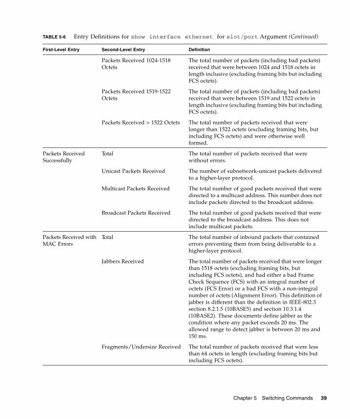
Packets Received 1024-1518Octets
The total number of packets (including bad packets)received that were between 1024 and 1518 octets inlength inclusive (excluding framing bits but includingFCS octets).
Packets Received 1519-1522Octets
The total number of packets (including bad packets)received that were between 1519 and 1522 octets inlength inclusive (excluding framing bits but includingFCS octets).
Packets Received > 1522 Octets The total number of packets received that werelonger than 1522 octets (excluding framing bits, butincluding FCS octets) and were otherwise wellformed.
Packets ReceivedSuccessfully
Total The total number of packets received that werewithout errors.
Unicast Packets Received The number of subnetwork-unicast packets deliveredto a higher-layer protocol.
Multicast Packets Received The total number of good packets received that weredirected to a multicast address. This number does notinclude packets directed to the broadcast address.
Broadcast Packets Received The total number of good packets received that weredirected to the broadcast address. This does notinclude multicast packets.
Packets Received withMAC Errors
Total The total number of inbound packets that containederrors preventing them from being deliverable to ahigher-layer protocol.
Jabbers Received The total number of packets received that were longerthan 1518 octets (excluding framing bits, butincluding FCS octets), and had either a bad FrameCheck Sequence (FCS) with an integral number ofoctets (FCS Error) or a bad FCS with a non-integralnumber of octets (Alignment Error). This definition ofjabber is different than the definition in IEEE-802.3section 8.2.1.5 (10BASE5) and section 10.3.1.4(10BASE2). These documents define jabber as thecondition where any packet exceeds 20 ms. Theallowed range to detect jabber is between 20 ms and150 ms.
Fragments/Undersize Received The total number of packets received that were lessthan 64 octets in length (excluding framing bits butincluding FCS octets).
TABLE 5-6 Entry Definitions for show interface ethernet for slot/port Argument (Continued)
First-Level Entry Second-Level Entry Definition
Chapter 5 Switching Commands 39

Alignment Errors The total number of packets received that had alength (excluding framing bits, but including FCSoctets) of between 64 and 1518 octets, inclusive, buthad a bad Frame Check Sequence (FCS) with a non-integral number of octets.
Rx FCS Errors The total number of packets received that had alength (excluding framing bits, but including FCSoctets) of between 64 and 1518 octets, inclusive, buthad a bad Frame Check Sequence (FCS) with anintegral number of octets.
Overruns The total number of frames discarded as this portwas overloaded with incoming packets, and couldnot keep up with the inflow.
Received Packets notforwarded
Total A count of valid frames received which werediscarded (that is, filtered) by the forwarding process.
Local Traffic Frames The total number of frames dropped in theforwarding process because the destination addresswas located off of this port.
802.3x Pause Frames Received A count of MAC Control frames received on thisinterface with an opcode indicating the PAUSEoperation. This counter does not increment when theinterface is operating in half-duplex mode.
Unacceptable Frame Type The number of frames discarded from this port dueto being an unacceptable frame type.
VLAN Membership Mismatch The number of frames discarded on this port due toingress filtering.
VLAN Viable Discards The number of frames discarded on this port when alookup on a particular VLAN occurs while that entryin the VLAN table is being modified, or if the VLANhas not been configured.
Multicast Tree Viable Discards The number of frames discarded when a lookup in themulticast tree for a VLAN occurs while that tree isbeing modified.
Reserved Address Discards The number of frames discarded that are destined toan IEEE 802.1 reserved address and are not supportedby the system.
Broadcast Storm Recovery The number of frames discarded that are destined forFF:FF:FF:FF:FF:FF when Broadcast StormRecovery is enabled.
CFI Discards The number of frames discarded that have CFI bit setand the addresses in RIF are in non-canonical format.
TABLE 5-6 Entry Definitions for show interface ethernet for slot/port Argument (Continued)
First-Level Entry Second-Level Entry Definition
40 Sun Netra CP3140 Switch Software Reference Manual • January 2010

Upstream Threshold The number of frames discarded due to lack of celldescriptors available for that packet’s priority level.
Packets TransmittedOctets
Total Bytes The total number of octets of data (including those inbad packets) received on the network (excludingframing bits but including FCS octets). This object canbe used as a reasonable estimate of Ethernetutilization. If greater precision is desired, theetherStatsPkts and etherStatsOctets objects should besampled before and after a common interval.
Packets Transmitted 64 Octets The total number of packets (including bad packets)received that were 64 octets in length (excludingframing bits but including FCS octets).
Packets Transmitted 65-127Octets
The total number of packets (including bad packets)received that were between 65 and 127 octets inlength inclusive (excluding framing bits butincluding FCS octets).
Packets Transmitted 128-255Octets
The total number of packets (including bad packets)received that were between 128 and 255 octets inlength inclusive (excluding framing bits but includingFCS octets).
Packets Transmitted 256-511Octets
The total number of packets (including bad packets)received that were between 256 and 511 octets inlength inclusive (excluding framing bits but includingFCS octets).
Packets Transmitted 512-1023Octets
The total number of packets (including bad packets)received that were between 512 and 1023 octets inlength inclusive (excluding framing bits but includingFCS octets).
Packets Transmitted 1024-1518Octets
The total number of packets (including bad packets)received that were between 1024 and 1518 octets inlength inclusive (excluding framing bits butincluding FCS octets).
Packets Transmitted 1519-1522Octets
The total number of packets (including bad packets)received that were between 1519 and 1522 octets inlength inclusive (excluding framing bits butincluding FCS octets).
Max Info The maximum size of the Info (non-MAC) field thatthis port will receive or transmit.
Packets TransmittedSuccessfully
Total The number of frames that have been transmitted bythis port to its segment.
TABLE 5-6 Entry Definitions for show interface ethernet for slot/port Argument (Continued)
First-Level Entry Second-Level Entry Definition
Chapter 5 Switching Commands 41

Unicast Packets Transmitted The total number of packets that higher-levelprotocols requested be transmitted to a subnetwork-unicast address, including those that were discardedor not sent.
Multicast Packets Transmitted The total number of packets that higher-levelprotocols requested be transmitted to a Multicastaddress, including those that were discarded or notsent.
Broadcast Packets Transmitted The total number of packets that higher-levelprotocols requested be transmitted to the Broadcastaddress, including those that were discarded or notsent.
Transmit Errors Total Errors The sum of Single, Multiple, and Excessive Collisions.
Tx FCS Errors The total number of packets transmitted that had alength (excluding framing bits, but including FCSoctets) of between 64 and 1518 octets, inclusive, buthad a bad Frame Check Sequence (FCS) with anintegral number of octets
Oversized The total number of frames that exceeded the maxpermitted frame size. This counter has a maxincrement rate of 815 counts per sec. at 10 Mbit/sec.
Underrun Errors The total number of frames discarded because thetransmit FIFO buffer became empty during frametransmission.
Transmit Discards Total Discards The sum of single-collision frames discarded,multiple-collision frames discarded, and excessiveframes discarded.
Single Collision Frames A count of the number of successfully transmittedframes on a particular interface for whichtransmission is inhibited by exactly one collision.
Multiple Collision Frames A count of the number of successfully transmittedframes on a particular interface for whichtransmission is inhibited by more than one collision.
Excessive Collisions A count of frames for which transmission on aparticular interface fails due to excessive collisions.
Port Membership The number of frames discarded on egress for thisport due to egress filtering being enabled.
VLAN Viable Discards The number of frames discarded on this port when alookup on a particular VLAN occurs while that entryin the VLAN table is being modified, or if the VLANhas not been configured.
TABLE 5-6 Entry Definitions for show interface ethernet for slot/port Argument (Continued)
First-Level Entry Second-Level Entry Definition
42 Sun Netra CP3140 Switch Software Reference Manual • January 2010
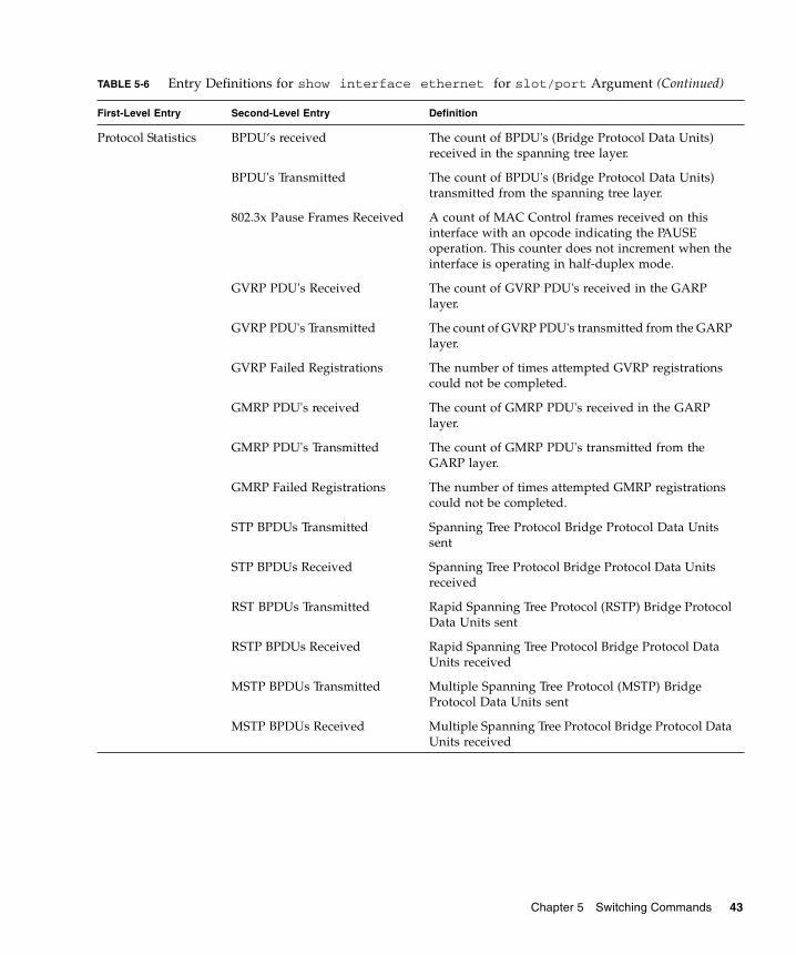
Protocol Statistics BPDU’s received The count of BPDU's (Bridge Protocol Data Units)received in the spanning tree layer.
BPDU's Transmitted The count of BPDU's (Bridge Protocol Data Units)transmitted from the spanning tree layer.
802.3x Pause Frames Received A count of MAC Control frames received on thisinterface with an opcode indicating the PAUSEoperation. This counter does not increment when theinterface is operating in half-duplex mode.
GVRP PDU's Received The count of GVRP PDU's received in the GARPlayer.
GVRP PDU's Transmitted The count of GVRP PDU's transmitted from the GARPlayer.
GVRP Failed Registrations The number of times attempted GVRP registrationscould not be completed.
GMRP PDU's received The count of GMRP PDU's received in the GARPlayer.
GMRP PDU's Transmitted The count of GMRP PDU's transmitted from theGARP layer.
GMRP Failed Registrations The number of times attempted GMRP registrationscould not be completed.
STP BPDUs Transmitted Spanning Tree Protocol Bridge Protocol Data Unitssent
STP BPDUs Received Spanning Tree Protocol Bridge Protocol Data Unitsreceived
RST BPDUs Transmitted Rapid Spanning Tree Protocol (RSTP) Bridge ProtocolData Units sent
RSTP BPDUs Received Rapid Spanning Tree Protocol Bridge Protocol DataUnits received
MSTP BPDUs Transmitted Multiple Spanning Tree Protocol (MSTP) BridgeProtocol Data Units sent
MSTP BPDUs Received Multiple Spanning Tree Protocol Bridge Protocol DataUnits received
TABLE 5-6 Entry Definitions for show interface ethernet for slot/port Argument (Continued)
First-Level Entry Second-Level Entry Definition
Chapter 5 Switching Commands 43

The display parameters, when the argument is ‘switchport’, are as follows.
Dot1x Statistics EAPOL Frames Received The number of valid EAPOL frames of any type thathave been received by this authenticator.
EAPOL Frames Transmitted The number of EAPOL frames of any type that havebeen transmitted by this authenticator.
Time Since CountersLast Cleared
The elapsed time, in days, hours, minutes, andseconds since the statistics for this port were lastcleared.
TABLE 5-7 Entry Definitions for show interface ethernet for switchportArgument
Entry Definition
Octets Received The total number of octets of data received by the processor(excluding framing bits but including FCS octets).
Total PacketsReceived WithoutError
The total number of packets (including broadcast packets andmulticast packets) received by the processor.
Unicast PacketsReceived
The number of subnetwork-unicast packets delivered to a higher-layer protocol.
Multicast PacketsReceived
The total number of packets received that were directed to a multicastaddress. This number does not include packets directed to thebroadcast address.
Broadcast PacketsReceived
The total number of packets received that were directed to thebroadcast address. This does not include multicast packets.
Receive PacketsDiscarded
The number of inbound packets which were chosen to be discardedeven though no errors had been detected to prevent their beingdeliverable to a higher-layer protocol. A possible reason fordiscarding a packet could be to free up buffer space.
Octets Transmitted The total number of octets transmitted out of the interface, includingframing characters.
Packets Transmittedwithout Errors
The total number of packets transmitted out of the interface.
Unicast PacketsTransmitted
The total number of packets that higher-level protocols requested betransmitted to a subnetwork-unicast address, including those thatwere discarded or not sent.
TABLE 5-6 Entry Definitions for show interface ethernet for slot/port Argument (Continued)
First-Level Entry Second-Level Entry Definition
44 Sun Netra CP3140 Switch Software Reference Manual • January 2010

show logging
This command displays the trap log maintained by the switch. The trap log containsa maximum of 256 entries that wrap.
■ Format – show logging
■ Mode – Privileged EXEC
Multicast PacketsTransmitted
The total number of packets that higher-level protocols requested betransmitted to a Multicast address, including those that werediscarded or not sent.
Broadcast PacketsTransmitted
The total number of packets that higher-level protocols requested betransmitted to the Broadcast address, including those that werediscarded or not sent.
Transmit PacketsDiscarded
The number of outbound packets which were chosen to be discardedeven though no errors had been detected to prevent their beingdeliverable to a higher-layer protocol. A possible reason fordiscarding a packet could be to free up buffer space.
Most Address EntriesEver Used
The highest number of Forwarding Database Address Table entriesthat have been learned by this switch since the most recent reboot.
Address Entries inUse
The number of Learned and static entries in the Forwarding DatabaseAddress Table for this switch.
Maximum VLANEntries
The maximum number of Virtual LANs (VLANs) allowed on thisswitch.
Most VLAN EntriesEver Used
The largest number of VLANs that have been active on this switchsince the last reboot.
Static VLAN Entries The number of presently active VLAN entries on this switch thathave been created statically.
Dynamic VLANEntries
The number of presently active VLAN entries on this switch thathave been created by GVRP registration.
VLAN Deletes The number of VLANs on this switch that have been created andthen deleted since the last reboot.
Time Since CountersLast Cleared
The elapsed time, in days, hours, minutes, and seconds, since thestatistics for this switch were last cleared.
TABLE 5-7 Entry Definitions for show interface ethernet for switchportArgument (Continued)
Entry Definition
Chapter 5 Switching Commands 45

Note – Trap log information is not retained across a switch reset.
show mac-addr-table
This command displays the forwarding database entries. If the command is enteredwith no parameter, the entire table is displayed. This is the same as entering theoptional all parameter. Alternatively, the administrator can enter a MAC Addressto display the table entry for the requested MAC address and all entries followingthe requested MAC address.
■ Format – show mac-addr-table [<macaddr> | all]
■ Mode – Privileged EXEC
TABLE 5-8 Entry Definitions for show logging
Entry Definition
Number of Traps sincelast reset
The number of traps that have occurred since the last reset of thisdevice.
Number of Trapssince log lastdisplayed
The number of traps that have occurred since the traps were lastdisplayed. Getting the traps by any method (terminal interfacedisplay, Web display, upload file from switch etc.) will result in thiscounter being cleared to 0.
Log The sequence number of this trap.
System Up Time The relative time since the last reboot of the switch at which this trapoccurred.
Trap The relevant information of this trap.
TABLE 5-9 Entry Definitions for show mac-addr-table
Entry Definition
Mac Address A unicast MAC address for which the switch has forwarding and orfiltering information. The format is 6 or 8 two-digit hexadecimalnumbers that are separated by colons, for example 01:23:45:67:89:AB.In an IVL system the MAC address will be displayed as 8 bytes.
46 Sun Netra CP3140 Switch Software Reference Manual • January 2010

show msglog
This command displays the message log maintained by the switch. The message logcontains system trace information.
The trap log contains a maximum of 256 entries that wrap.
■ Format – show msglog
■ Mode – Privileged EXEC
Note – Message log information is not retained across a switch reset.
Slot/Port The port which this address was learned.
if Index This object indicates the ifIndex of the interface table entry associatedwith this port.
Status The status of this entry. The meanings of the values are:• Static – The value of the corresponding instance was added by the
system or a user when a static MAC filter was defined. It cannot berelearned.
• Learned – The value of the corresponding instance was learned byobserving the source MAC addresses of incoming traffic, and iscurrently in use.
• Management – The value of the corresponding instance (systemMAC address) is also the value of an existing instance ofdot1dStaticAddress. It is identified with interface 0/1 and iscurrently used when enabling VLANs for routing.
• Self – The value of the corresponding instance is the address of oneof the switch’s physical interfaces (the system’s own MAC address).
• GMRP Learned – The value of the corresponding was learned viaGMRP and applies to Multicast.
• Other – The value of the corresponding instance does not fall intoone of the other categories.
TABLE 5-10 Entry Definitions for show msglog
Entry Definition
Message The message that has been logged.
TABLE 5-9 Entry Definitions for show mac-addr-table
Entry Definition
Chapter 5 Switching Commands 47

show running-config
This command is used to display the current setting of different protocol packagessupported on the switch. This command displays only those parameters with valuesof that from default value. The output is displayed in the script format, which can beused to configure another switch with same configuration.
■ Format – show running-config
■ Mode – Privileged EXEC
show sysinfo
This command displays switch information.
■ Format – show sysinfo
■ Mode – Privileged EXEC
snmp-server
This command sets the name and the physical location of the switch, and theorganization responsible for the network.The range for name, location and contact isfrom 1 to 31 alphanumeric characters.
■ Default – none
■ Format – snmp-server {sysname <name> | location <loc> |contact <con>}
■ Mode – Global Config
TABLE 5-11 Entry Definitions for show sysinfo
Entry Definition
Switch Description Text used to identify this switch.
System Name Name used to identify the switch.
System Location Text used to identify the location of the switch. May be up to 31alphanumeric characters. The factory default is blank.
System Contact Text used to identify a contact person for this switch. May be up to 31alphanumeric characters. The factory default is blank.
System ObjectID The base object ID for the switch’s enterprise MIB.
System Up Time The time in days, hours, and minutes since the last switch reboot.
MIBs Supported A list of MIBs supported by this agent.
48 Sun Netra CP3140 Switch Software Reference Manual • January 2010

System Management CommandsThese commands manage the switch and show current management settings. Thecommands are divided into two functional groups:
■ Show commands display switch settings, statistics, and other information.
■ Configuration commands configure features and options of the switch. For everyconfiguration command, there is a show command that displays the configurationsetting.
bridge aging-time
This command configures the forwarding database address aging timeout inseconds. In an IVL system, the [fdbid | all] parameter is required.
■ Default – 300
■ Format – bridge aging-time <10-1,000,000> [fdbid | all]
■ Mode – Global Config
no bridge aging-time
This command sets the forwarding database address aging timeout to 300 seconds.In an IVL system, the [fdbid | all] parameter is required.
■ Format – no bridge aging-time [fdbid | all]
■ Mode – Global Config
TABLE 5-12 Entry Definitions for bridge aging-time
Entry Definition
Seconds The <seconds> parameter must be within the range of 10 to 1,000,000seconds.
Forwarding DatabaseID
Fdbid (Forwarding database ID) indicates which forwardingdatabase's aging timeout is being configured. The All option is usedto configure all forwarding database's agetime.
Chapter 5 Switching Commands 49
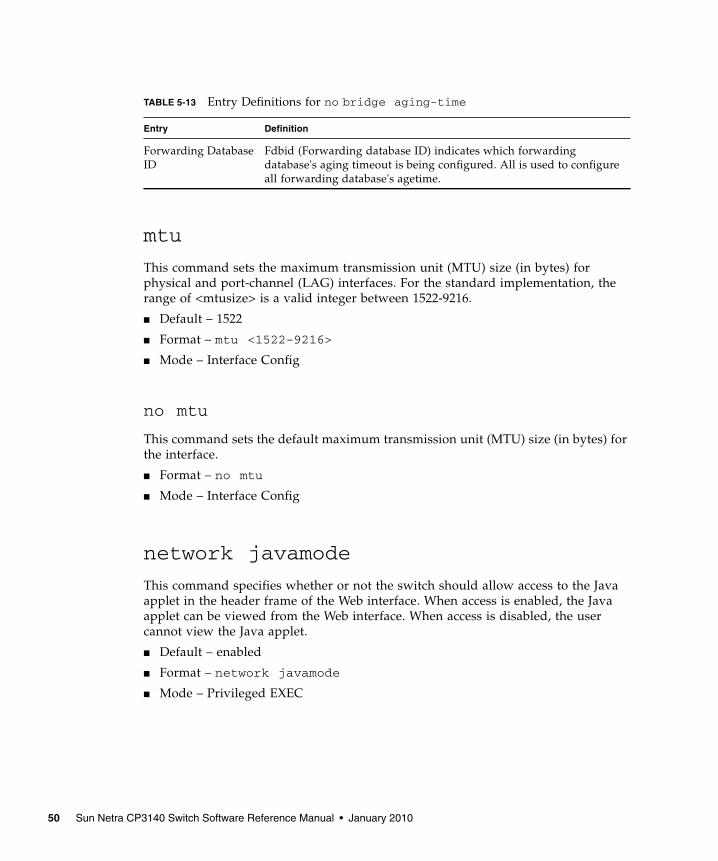
mtu
This command sets the maximum transmission unit (MTU) size (in bytes) forphysical and port-channel (LAG) interfaces. For the standard implementation, therange of <mtusize> is a valid integer between 1522-9216.
■ Default – 1522
■ Format – mtu <1522-9216>
■ Mode – Interface Config
no mtu
This command sets the default maximum transmission unit (MTU) size (in bytes) forthe interface.
■ Format – no mtu
■ Mode – Interface Config
network javamode
This command specifies whether or not the switch should allow access to the Javaapplet in the header frame of the Web interface. When access is enabled, the Javaapplet can be viewed from the Web interface. When access is disabled, the usercannot view the Java applet.
■ Default – enabled
■ Format – network javamode
■ Mode – Privileged EXEC
TABLE 5-13 Entry Definitions for no bridge aging-time
Entry Definition
Forwarding DatabaseID
Fdbid (Forwarding database ID) indicates which forwardingdatabase's aging timeout is being configured. All is used to configureall forwarding database's agetime.
50 Sun Netra CP3140 Switch Software Reference Manual • January 2010

no network javamode
This command disallows access to the Java applet in the header frame of the Webinterface. When access is disabled, the user cannot view the Java applet.
■ Format – no network javamode
■ Mode – Privileged EXEC
network mac-address
This command sets locally administered MAC addresses. The following rules apply:
■ Bit 6 of byte 0 (called the U/L bit) indicates whether the address is universallyadministered (b'0') or locally administered (b'1').
■ Bit 7 of byte 0 (called the I/G bit) indicates whether the destination address is anindividual address (b'0') or a group address (b'1').
The second character, of the twelve character macaddr, must be 2, 6, A or E.
A locally administered address must have bit 6 On (b'1') and bit 7 Off (b'0').
■ Format – network mac-address <macaddr>
■ Mode – Privileged EXEC
network mac-type
This command specifies whether the burned in MAC address or the locally-administered MAC address is used.
■ Default – burnedin
■ Format – network mac-type {local | burnedin}
■ Mode – Privileged EXEC
no network mac-type
This command resets the value of MAC address to its default.
■ Format – no network mac-type
■ Mode – Privileged EXEC
Chapter 5 Switching Commands 51
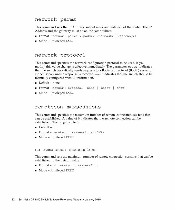
network parms
This command sets the IP Address, subnet mask and gateway of the router. The IPAddress and the gateway must be on the same subnet.
■ Format – network parms <ipaddr> <netmask> [<gateway>]
■ Mode – Privileged EXEC
network protocol
This command specifies the network configuration protocol to be used. If youmodify this value change is effective immediately. The parameter bootp indicatesthat the switch periodically sends requests to a Bootstrap Protocol (BootP) server ora dhcp server until a response is received. none indicates that the switch should bemanually configured with IP information.
■ Default – none
■ Format – network protocol {none | bootp | dhcp}
■ Mode – Privileged EXEC
remotecon maxsessions
This command specifies the maximum number of remote connection sessions thatcan be established. A value of 0 indicates that no remote connection can beestablished. The range is 0 to 5.
■ Default – 5
■ Format – remotecon maxsessions <0-5>
■ Mode – Privileged EXEC
no remotecon maxsessions
This command sets the maximum number of remote connection sessions that can beestablished to the default value.
■ Format – no remotecon maxsessions
■ Mode – Privileged EXEC
52 Sun Netra CP3140 Switch Software Reference Manual • January 2010

remotecon timeout
This command sets the remote connection session timeout value, in minutes. Asession is active as long as the session has been idle for the value set. A value of 0indicates that a session remains active indefinitely. The time is a decimal value from0 to 160.
Note – Changing the timeout value for active sessions does not become effectiveuntil the session is reaccessed. Any keystroke will also activate the new timeoutduration.
■ Default – 5
■ Format – remotecon timeout <0-160>
■ Mode – Privileged EXEC
no remotecon timeout
This command sets the remote connection session timeout value, in minutes, to thedefault.
Note – Changing the timeout value for active sessions does not become effectiveuntil the session is reaccessed. Any keystroke will also activate the new timeoutduration.
■ Format – no remotecon timeout
■ Mode – Privileged EXEC
serial baudrate
This command specifies the communication rate of the terminal interface. Thesupported rates are 1200, 2400, 4800, 9600, 19200, 38400, 57600, 115200.
■ Default – 9600
■ Format – serial baudrate {1200 | 2400 | 4800 | 9600 | 19200 |38400 | 57600 | 115200}
■ Mode – Line Config
Chapter 5 Switching Commands 53

no serial baudrate
This command sets the communication rate of the terminal interface.
■ Format – no serial baudrate
■ Mode – Line Config
serial timeout
This command specifies the maximum connect time (in minutes) without consoleactivity. A value of 0 indicates that a console can be connected indefinitely. The timerange is 0 to 160.
■ Default – 5
■ Format – serial timeout <0-160>
■ Mode – Line Config
no serial timeout
This command sets the maximum connect time (in minutes) without console activity.
■ Format – no serial timeout
■ Mode – Line Config
set prompt
This command changes the name of the prompt. The length of name may be up to 64alphanumeric characters.
■ Format – set prompt <prompt string>
■ Mode – Privileged EXEC
serviceport ip
This command sets the IP address, the netmask and the gateway of the router.
■ Format – serviceport ip <ipaddr> <netmask> [gateway]
■ Mode – Privileged EXEC
54 Sun Netra CP3140 Switch Software Reference Manual • January 2010

serviceport protocol
This command specifies the servicePort configuration protocol. If you modify thisvalue, the change takes effect immediately.
■ Format – serviceport protocol {none | bootp | dhcp}
■ Mode – Privileged EXEC
show forwardingdb agetime
This command displays the timeout for address aging. In an IVL system, the [fdbid| all] parameter is required.
■ Default – all
■ Format – show forwardingdb agetime [fdbid | all]
■ Mode – Privileged EXEC
show network
This command displays configuration settings associated with the switch's networkinterface. The network interface is the logical interface used for in-band connectivitywith the switch via any of the switch's front panel ports. The configurationparameters associated with the switch's network interface do not affect theconfiguration of the front panel ports through which traffic is switched or routed.
■ Format – show network
■ Mode – Privileged EXEC and User EXEC
TABLE 5-14 Entry Definitions for show forwardingdb agetime
Entry Definition
Forwarding DB ID Fdbid (Forwarding database ID) indicates the forwarding databasewhose aging timeout is to be shown. The all option is used to displaythe aging timeouts associated with all forwarding databases. Thisfield displays the forwarding database ID in an IVL system.
Agetime In an IVL system, this parameter displays the address aging timeoutfor the associated forwarding database.
Chapter 5 Switching Commands 55

TABLE 5-15 Entry Definitions for show network
Entry Definition
IP Address The IP address of the interface. The factory default value is 0.0.0.0
Subnet Mask The IP subnet mask for this interface. The factory default value is0.0.0.0
Default Gateway The default gateway for this IP interface. The factory default value is0.0.0.0
Burned In MACAddress
The burned in MAC address used for in-band connectivity.
Locally AdministeredMAC Address
If desired, a locally administered MAC address can be configured forin-band connectivity. To take effect, 'MAC Address Type' must be setto 'Locally Administered'. Enter the address as twelve hexadecimaldigits (6 bytes) with a colon between each byte. Bit 1 of byte 0 mustbe set to a 1 and bit 0 to a 0; that is, byte 0 should have the followingmask 'xxxx xx10'. The MAC address used by this bridge when it mustbe referred to in a unique fashion. It is recommended that this be thenumerically smallest MAC address of all ports that belong to thisbridge. However it is only required to be unique. When concatenatedwith dot1dStpPriority a unique BridgeIdentifier is formed which isused in the Spanning Tree Protocol.
MAC Address Type Specifies which MAC address should be used for in-bandconnectivity. The choices are the burned in or the LocallyAdministered address. The factory default is to use the burned inMAC address.
NetworkConfigurationProtocol Current
Indicates which network protocol is being used. The options are:• bootp• dhcp• none.
Java Mode Specifies if the switch should allow access to the Java applet in theheader frame. Enabled means the applet can be viewed. The factorydefault is disabled.
Management VLANID
Specifies the management VLAN ID.
56 Sun Netra CP3140 Switch Software Reference Manual • January 2010
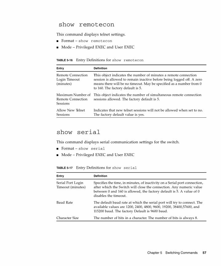
show remotecon
This command displays telnet settings.
■ Format – show remotecon
■ Mode – Privileged EXEC and User EXEC
show serial
This command displays serial communication settings for the switch.
■ Format – show serial
■ Mode – Privileged EXEC and User EXEC
TABLE 5-16 Entry Definitions for show remotecon
Entry Definition
Remote ConnectionLogin Timeout(minutes)
This object indicates the number of minutes a remote connectionsession is allowed to remain inactive before being logged off. A zeromeans there will be no timeout. May be specified as a number from 0to 160. The factory default is 5.
Maximum Number ofRemote ConnectionSessions
This object indicates the number of simultaneous remote connectionsessions allowed. The factory default is 5.
Allow New TelnetSessions
Indicates that new telnet sessions will not be allowed when set to no.The factory default value is yes.
TABLE 5-17 Entry Definitions for show serial
Entry Definition
Serial Port LoginTimeout (minutes)
Specifies the time, in minutes, of inactivity on a Serial port connection,after which the Switch will close the connection. Any numeric valuebetween 0 and 160 is allowed, the factory default is 5. A value of 0disables the timeout.
Baud Rate The default baud rate at which the serial port will try to connect. Theavailable values are 1200, 2400, 4800, 9600, 19200, 38400,57600, and115200 baud. The factory Default is 9600 baud.
Character Size The number of bits in a character. The number of bits is always 8.
Chapter 5 Switching Commands 57
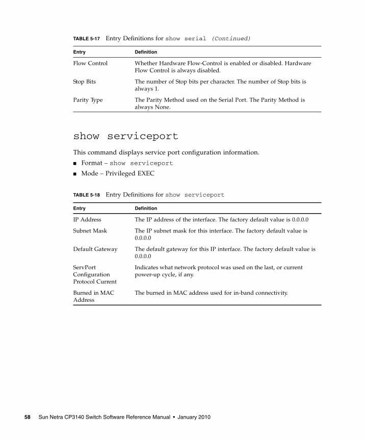
show serviceport
This command displays service port configuration information.
■ Format – show serviceport
■ Mode – Privileged EXEC
Flow Control Whether Hardware Flow-Control is enabled or disabled. HardwareFlow Control is always disabled.
Stop Bits The number of Stop bits per character. The number of Stop bits isalways 1.
Parity Type The Parity Method used on the Serial Port. The Parity Method isalways None.
TABLE 5-18 Entry Definitions for show serviceport
Entry Definition
IP Address The IP address of the interface. The factory default value is 0.0.0.0
Subnet Mask The IP subnet mask for this interface. The factory default value is0.0.0.0
Default Gateway The default gateway for this IP interface. The factory default value is0.0.0.0
ServPortConfigurationProtocol Current
Indicates what network protocol was used on the last, or currentpower-up cycle, if any.
Burned in MACAddress
The burned in MAC address used for in-band connectivity.
TABLE 5-17 Entry Definitions for show serial (Continued)
Entry Definition
58 Sun Netra CP3140 Switch Software Reference Manual • January 2010

SNMP Community Commands
show snmpcommunity
This command displays SNMP community information. Six communities aresupported. You can add, change, or delete communities. The switch does not have tobe reset for changes to take effect.
The SNMP agent of the switch complies with SNMP Version 1 (for more about theSNMP specification, see the SNMP RFCs). The SNMP agent sends traps throughTCP/IP to an external SNMP manager based on the SNMP configuration (the trapreceiver and other SNMP community parameters).
■ Format – show snmpcommunity
■ Mode – Privileged EXEC
TABLE 5-19 Entry Definitions for show snmpcommunity
Entry Definition
SNMP CommunityName
The community string to which this entry grants access. A valid entryis a case-sensitive alphanumeric string of up to 16 characters. Eachrow of this table must contain a unique community name.
Client IP Address An IP address (or portion thereof) from which this device will acceptSNMP packets with the associated community. The requesting entity'sIP address is ANDed with the Subnet Mask before being compared tothe IP Address. Note that if the Subnet Mask is set to 0.0.0.0, an IPAddress of 0.0.0.0 matches all IP addresses. The default value is0.0.0.0
Client IP Mask A mask to be ANDed with the requesting entity's IP address beforecomparison with IP Address. If the result matches with IP Addressthen the address is an authenticated IP address. For example, if the IPAddress = 9.47.128.0 and the corresponding Subnet Mask =255.255.255.0 a range of incoming IP addresses would match; that is,the incoming IP Address could equal 9.47.128.0 - 9.47.128.255. Thedefault value is 0.0.0.0
Access Mode The access level for this community string.
Status The status of this community access entry.
Chapter 5 Switching Commands 59
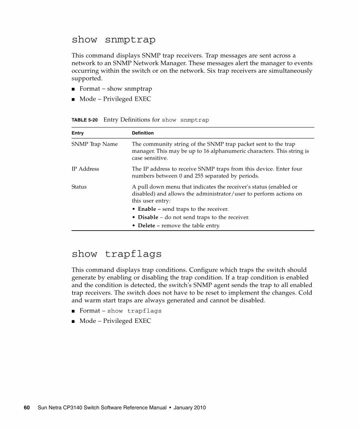
show snmptrap
This command displays SNMP trap receivers. Trap messages are sent across anetwork to an SNMP Network Manager. These messages alert the manager to eventsoccurring within the switch or on the network. Six trap receivers are simultaneouslysupported.
■ Format – show snmptrap
■ Mode – Privileged EXEC
show trapflags
This command displays trap conditions. Configure which traps the switch shouldgenerate by enabling or disabling the trap condition. If a trap condition is enabledand the condition is detected, the switch's SNMP agent sends the trap to all enabledtrap receivers. The switch does not have to be reset to implement the changes. Coldand warm start traps are always generated and cannot be disabled.
■ Format – show trapflags
■ Mode – Privileged EXEC
TABLE 5-20 Entry Definitions for show snmptrap
Entry Definition
SNMP Trap Name The community string of the SNMP trap packet sent to the trapmanager. This may be up to 16 alphanumeric characters. This string iscase sensitive.
IP Address The IP address to receive SNMP traps from this device. Enter fournumbers between 0 and 255 separated by periods.
Status A pull down menu that indicates the receiver's status (enabled ordisabled) and allows the administrator/user to perform actions onthis user entry:• Enable – send traps to the receiver.• Disable – do not send traps to the receiver.• Delete – remove the table entry.
60 Sun Netra CP3140 Switch Software Reference Manual • January 2010

snmp-server community
This command adds (and names) a new SNMP community. A community name is aname associated with the switch and with a set of SNMP managers that manage itwith a specified privileged level. The length of name can be up to 16 case-sensitivecharacters.
Note – Community names in the SNMP community table must be unique. Whenmaking multiple entries using the same community name, the first entry is kept andprocessed and all duplicate entries are ignored.
■ Default – Two default community names: Public and Private. You can replacethese default community names with unique identifiers for each community. Thedefault values for the remaining four community names are blank.
■ Format – snmp-server community <name>
■ Mode – Global Config
TABLE 5-21 Entry Definitions for show trapflags
Entry Definition
Authentication Flag May be enabled or disabled. The factory default is enabled. Indicateswhether authentication failure traps will be sent.
Link Up/Down Flag May be enabled or disabled. The factory default is enabled. Indicateswhether link status traps will be sent.
Multiple Users Flag May be enabled or disabled. The factory default is enabled. Indicateswhether a trap will be sent when the same user ID is logged into theswitch more than once at the same time (either via telnet or serialport).
Spanning Tree Flag May be enabled or disabled. The factory default is enabled. Indicateswhether spanning tree traps will be sent.
Broadcast Storm Flag May be enabled or disabled. The factory default is enabled. Indicateswhether broadcast storm traps will be sent.
DVMRP Traps May be enabled or disabled. The factory default is disabled. Indicateswhether DVMRP traps will be sent.
OSPF Traps May be enabled or disabled. The factory default is disabled. Indicateswhether OSPF traps will be sent.
PIM Traps May be enabled or disabled. The factory default is disabled. Indicateswhether PIM traps will be sent.
Chapter 5 Switching Commands 61
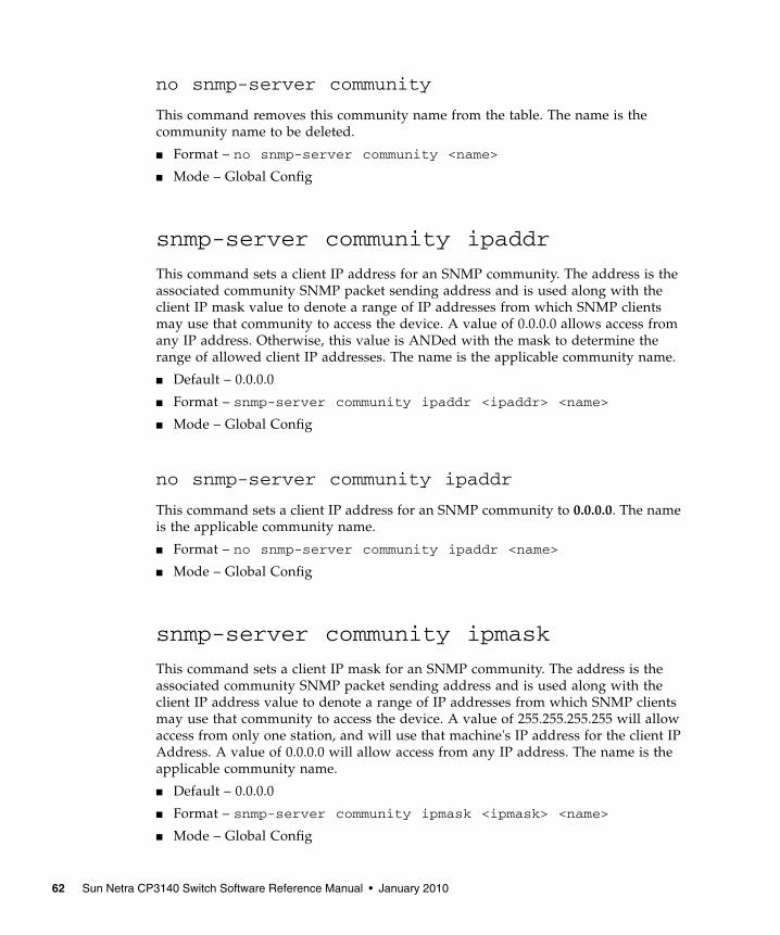
no snmp-server community
This command removes this community name from the table. The name is thecommunity name to be deleted.
■ Format – no snmp-server community <name>
■ Mode – Global Config
snmp-server community ipaddr
This command sets a client IP address for an SNMP community. The address is theassociated community SNMP packet sending address and is used along with theclient IP mask value to denote a range of IP addresses from which SNMP clientsmay use that community to access the device. A value of 0.0.0.0 allows access fromany IP address. Otherwise, this value is ANDed with the mask to determine therange of allowed client IP addresses. The name is the applicable community name.
■ Default – 0.0.0.0
■ Format – snmp-server community ipaddr <ipaddr> <name>
■ Mode – Global Config
no snmp-server community ipaddr
This command sets a client IP address for an SNMP community to 0.0.0.0. The nameis the applicable community name.
■ Format – no snmp-server community ipaddr <name>
■ Mode – Global Config
snmp-server community ipmask
This command sets a client IP mask for an SNMP community. The address is theassociated community SNMP packet sending address and is used along with theclient IP address value to denote a range of IP addresses from which SNMP clientsmay use that community to access the device. A value of 255.255.255.255 will allowaccess from only one station, and will use that machine's IP address for the client IPAddress. A value of 0.0.0.0 will allow access from any IP address. The name is theapplicable community name.
■ Default – 0.0.0.0
■ Format – snmp-server community ipmask <ipmask> <name>
■ Mode – Global Config
62 Sun Netra CP3140 Switch Software Reference Manual • January 2010

no snmp-server community ipmask
This command sets a client IP mask for an SNMP community to 0.0.0.0. The name isthe applicable community name. The community name may be up to 16alphanumeric characters.
■ Format – no snmp-server community ipmask <name>
■ Mode – Global Config
snmp-server community mode
This command activates an SNMP community. If a community is enabled, an SNMPmanager associated with this community manages the switch according to its accessright. If the community is disabled, no SNMP requests using this community areaccepted. In this case the SNMP manager associated with this community cannotmanage the switch until the Status is changed back to Enable.
■ Default – The default private and public communities are enabled by default. Thefour undefined communities are disabled by default.
■ Format – snmp-server community mode <name>
■ Mode – Global Config
no snmp-server community mode
This command deactivates an SNMP community. If the community is disabled, noSNMP requests using this community are accepted. In this case the SNMP managerassociated with this community cannot manage the switch until the Status ischanged back to Enable.
■ Format – no snmp-server community mode <name>
■ Mode – Global Config
snmp-server community ro
This command restricts access to switch information. The access mode is read-only(also called public).
■ Format – snmp-server community ro <name>
■ Mode – Global Config
Chapter 5 Switching Commands 63

snmp-server community rw
This command restricts access to switch information. The access mode is read/write(also called private).
■ Format – snmp-server community rw <name>
■ Mode – Global Config
snmp-server enable traps
This command enables the Authentication Flag.
■ Default – enabled
■ Format – snmp-server enable traps
■ Mode – Global Config
no snmp-server enable traps
This command disables the Authentication Flag.
■ Format – no snmp-server enable traps
■ Mode – Global Config
snmp-server enable traps bcaststorm
This command enables the broadcast storm trap. When enabled, broadcast stormtraps are sent only if the broadcast storm recovery mode setting associated with theport is enabled .
■ Default – enabled
■ Format – snmp-server enable traps bcaststorm
■ Mode – Global Config
no snmp-server enable traps bcaststorm
This command disables the broadcast storm trap. When enabled, broadcast stormtraps are sent only if the broadcast storm recovery mode setting associated with theport is enabled .
■ Format – no snmp-server enable traps bcaststorm
■ Mode – Global Config
64 Sun Netra CP3140 Switch Software Reference Manual • January 2010
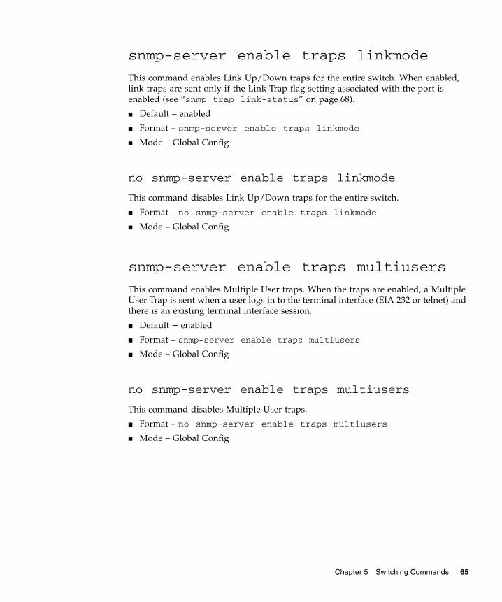
snmp-server enable traps linkmode
This command enables Link Up/Down traps for the entire switch. When enabled,link traps are sent only if the Link Trap flag setting associated with the port isenabled (see “snmp trap link-status” on page 68).
■ Default – enabled
■ Format – snmp-server enable traps linkmode
■ Mode – Global Config
no snmp-server enable traps linkmode
This command disables Link Up/Down traps for the entire switch.
■ Format – no snmp-server enable traps linkmode
■ Mode – Global Config
snmp-server enable traps multiusers
This command enables Multiple User traps. When the traps are enabled, a MultipleUser Trap is sent when a user logs in to the terminal interface (EIA 232 or telnet) andthere is an existing terminal interface session.
■ Default – enabled
■ Format – snmp-server enable traps multiusers
■ Mode – Global Config
no snmp-server enable traps multiusers
This command disables Multiple User traps.
■ Format – no snmp-server enable traps multiusers
■ Mode – Global Config
Chapter 5 Switching Commands 65

snmp-server enable traps stpmode
This command enables the sending of new root traps and topology changenotification traps.
■ Default – enabled
■ Format – snmp-server enable traps stpmode
■ Mode – Global Config
no snmp-server enable traps stpmode
This command disables the sending of new root traps and topology changenotification traps.
■ Format – no snmp-server enable traps stpmode
■ Mode – Global Config
snmptrap
This command adds an SNMP trap name. The maximum length of name is 16 case-sensitive alphanumeric characters.
■ Default – The default name for the six undefined community names is Delete.
■ Format – snmptrap <name> <ipaddr>
■ Mode – Global Config
no snmptrap
This command deletes trap receivers for a community.
■ Format – no snmptrap <name> <ipaddr>
■ Mode – Global Config
66 Sun Netra CP3140 Switch Software Reference Manual • January 2010

snmptrap ipaddr
This command assigns an IP address to a specified community name. The maximumlength of name is 16 case-sensitive alphanumeric characters.
Note – IP addresses in the SNMP trap receiver table must be unique. If you makemultiple entries using the same IP address, the first entry is retained and processed.All duplicate entries are ignored.
■ Format – snmptrap ipaddr <name> <ipaddrold> <ipaddrnew>
■ Mode – Global Config
snmptrap mode
This command activates or deactivates an SNMP trap. Enabled trap receivers areactive (able to receive traps). Disabled trap receivers are inactive (not able to receivetraps).
■ Format – snmptrap mode <name> <ipaddr>
■ Mode – Global Config
no snmptrap mode
This command deactivates an SNMP trap. Disabled trap receivers are inactive (notable to receive traps).
■ Format – no snmptrap mode <name> <ipaddr>
■ Mode – Global Config
telnet
This command regulates new telnet sessions. If sessions are enabled, new telnetsessions can be established until there are no more sessions available. If sessions aredisabled, no new telnet sessions are established. An established session remainsactive until the session is ended or an abnormal network error ends it.
■ Default – enabled
■ Format – telnet
■ Mode – Privileged EXEC
Chapter 5 Switching Commands 67

no telnet
This command disables telnet sessions. If sessions are disabled, no new telnetsessions are established.
■ Format – no telnet
■ Mode – Privileged EXEC
snmp trap link-status
This command enables link status traps by interface.
Note – This command is valid only when the Link Up/Down Flag is enabled (see“snmp-server enable traps linkmode” on page 65).
■ Format – snmp trap link-status
■ Mode – Interface Config
no snmp trap link-status
This command disables link status traps by interface.
Note – This command is valid only when the Link Up/Down Flag is enabled (see“snmp-server enable traps linkmode” on page 65).
■ Format – no snmp trap link-status
■ Mode – Interface Config
snmp trap link-status all
This command enables link status traps for all interfaces.
Note – This command is valid only when the Link Up/Down Flag is enabled (see“snmp-server enable traps linkmode” on page 65).
■ Format – snmp trap link-status all
■ Mode – Global Config
68 Sun Netra CP3140 Switch Software Reference Manual • January 2010

no snmp trap link-status all
This command disables link status traps for all interfaces.
Note – This command is valid only when the Link Up/Down Flag is enabled ( (see“snmp-server enable traps linkmode” on page 65).
■ Format – no snmp trap link-status all
■ Mode – Global Config
Management VLAN CommandThis command is used to set the Management VLAN.
network mgmt_vlan
This command configures the Management VLAN ID.
■ Default – 1
■ Format – network mgmt_vlan <1-4021>
■ Mode – Privileged EXEC
Chapter 5 Switching Commands 69

System Configuration CommandsThis chapter provides a detailed explanation of the System configuration commands.The commands are divided into two functional groups:
■ Show commands display switch settings, statistics, and other information.
■ Configuration commands configure features and options of the switch. For everyconfiguration command, there is a show command that displays the configurationsetting.
addport
This command adds one port to the port-channel (LAG). The first interface is alogical unit, slot and port slot and port number of a configured port-channel.
Note – Before adding a port to a port-channel, set the physical mode of the port (see“speed” on page 73).
■ Format – addport <logical slot/port>
■ Mode – Interface Config
cablestatus
This command tests the status of the cable attached to an interface.
■ Format – cablestatus <slot/port>
■ Mode – Privileged EXEC
auto-negotiate
This command enables automatic negotiation on a port. The default value is enable.
■ Format – auto-negotiate
■ Mode – Interface Config
70 Sun Netra CP3140 Switch Software Reference Manual • January 2010
no auto-negotiate
This command disables automatic negotiation on a port.
Note – Automatic sensing is disabled when automatic negotiation is disabled.
■ Format – no auto-negotiate
■ Mode – Interface Config
auto-negotiate all
This command enables automatic negotiation on all ports. The default value isenable.
■ Format – auto-negotiate all
■ Mode – Global Config
no auto-negotiate all
This command disables automatic negotiation on all ports.
■ Format – no auto-negotiate all
■ Mode – Global Config
deleteport (Interface Config)
This command deletes the port from the port-channel (LAG). The interface is alogical unit, slot and port slot and port number of a configured port-channel.
■ Format – deleteport <logical slot/port>
■ Mode – Interface Config
deleteport (Global Config)
This command deletes all configured ports from the port-channel (LAG). Theinterface is a logical unit, slot and port slot and port number of a configured port-channel.
■ Format – deleteport {<logical slot/port> | all}
■ Mode – Global Config
Chapter 5 Switching Commands 71
monitor session
This command configures a probe port and a monitored port for monitor session(port monitoring). The first slot/port is the source monitored port and the secondslot/port is the destination probe port. If this command is executed while portmonitoring is enabled, it will have the effect of changing the probe and monitoredport values.
■ Format – monitor session source <slot/port> <destination><slot/port>
■ Mode – Global Config
no monitor session
This command removes the monitor session (port monitoring) designation fromboth the source probe port and the destination monitored port and removes theprobe port from all VLANs. The port must be manually re-added to any desiredVLANs.
■ Format – no monitor session
■ Mode – Global Config
monitor session mode
This command configures the monitor session (port monitoring) mode to enable.The probe and monitored ports must be configured before monitor session (portmonitoring) can be enabled. If enabled, the probe port will monitor all trafficreceived and transmitted on the physical monitored port. It is not necessary todisable port monitoring before modifying the probe and monitored ports.
■ Default – disabled
■ Format – monitor session mode
■ Mode – Global Config
no monitor session mode
This command sets the monitor session (port monitoring) mode to disable.
■ Format – no monitor session mode
■ Mode – Global Config
72 Sun Netra CP3140 Switch Software Reference Manual • January 2010

shutdown
This command disables a port.
■ Default – enabled
■ Format – shutdown
■ Mode – Interface Config
no shutdown
This command enables a port.
■ Format – no shutdown
■ Mode – Interface Config
shutdown all
This command disables all ports.
■ Default – enabled
■ Format – shutdown all
■ Mode – Global Config
no shutdown all
This command enables all ports.
■ Format – no shutdown all
■ Mode – Global Config
speed
This command sets the speed and duplex setting for the interface.
■ Format – speed {<100 | 10> <half-duplex | full-duplex>}
■ Mode – Interface Config
Acceptable values for the speed command are as follows.
Chapter 5 Switching Commands 73

speed all
This command sets the speed and duplex setting for all interfaces.
■ Format – speed all {<100 | 10> <half-duplex | full-duplex>}
■ Mode – Global Config
Acceptable values for the speed all command are as follows.
storm-control broadcast
This command enables broadcast storm recovery mode. If the mode is enabled,broadcast storm recovery with high and low thresholds is implemented.
The threshold implementation follows a percentage pattern. If the broadcast trafficon any Ethernet port exceeds the high threshold percentage (as shown in TABLE 5-24)of the link speed, the switch discards the broadcasts traffic until the broadcast trafficreturns to the low threshold percentage or less. The full implementation is depictedin the following table.
TABLE 5-22 Entry Definitions for speed
Entry Definition
100h 100BASE-T half duplex
100f 100BASE-T full duplex
10h 10BASE-T half duplex
10f 10BASE-T full duplex
TABLE 5-23 Entry Definitions for speed all
Entry Definition
100h 100BASE-T half-duplex
100f 100BASE-T full duplex
10h 10BASE-T half duplex
10f 10BASE-T full duplex
74 Sun Netra CP3140 Switch Software Reference Manual • January 2010

■ Format – storm-control broadcast
■ Mode – Global Config
no storm-control broadcast
This command disables broadcast storm recovery mode.
The threshold implementation follows a percentage pattern. If the broadcast trafficon any Ethernet port exceeds the high threshold percentage (as shown in TABLE 5-25)of the link speed, the switch discards the broadcasts traffic until the broadcast trafficreturns to the low threshold percentage or less. The full implementation is depictedin the following table.
■ Format – no storm-control broadcast
■ Mode – Global Config
TABLE 5-24 Broadcast Storm Recovery Thresholds
Link Speed High Low
10M 20 10
100M 5 2
1000M 5 2
TABLE 5-25 Broadcast Storm Recovery Thresholds
Link Speed High Low
10M 20 10
100M 5 2
1000M 5 2
Chapter 5 Switching Commands 75

storm-control flowcontrol
This command enables 802.3x flow control for the switch.
Note – This command only applies to full-duplex mode ports.
■ Default – disabled
■ Format – storm-control flowcontrol
■ Mode – Global Config
no storm-control flowcontrol
This command disables 802.3x flow control for the switch.
Note – This command only applies to full-duplex mode ports.
■ Format – no storm-control flowcontrol
■ Mode – Global Config
show mac-address-table multicast
This command displays the Multicast Forwarding Database (MFDB) information. Ifthe command is entered with no parameter, the entire table is displayed. This is thesame as entering the optional all parameter. The user can display the table entry forone MAC Address by specifying the MAC address as an optional parameter.
■ Format – show mac-address-table multicast <macaddr | all>
■ Mode – Privileged EXEC
76 Sun Netra CP3140 Switch Software Reference Manual • January 2010

show mac-address-table static
This command displays the Static MAC Filtering information for all Static MACFilters. If <all> is selected, all the Static MAC Filters in the system are displayed. If amacaddr is entered, a vlan must also be entered and the Static MAC Filterinformation will be displayed only for that MAC address and VLAN.
■ Format – show mac-address-table static {<macaddr> <vlanid> | all}
■ Mode – Privileged EXEC
TABLE 5-26 Entry Definitions for show mac-address-table multicast
Entry Definition
Mac Address A multicast MAC address for which the switch has forwarding and orfiltering information. The format is two-digit hexadecimal numbersthat are separated by colons, for example 01:23:45:67:89:AB. In an IVLsystem the MAC address will be displayed as a MAC address andVLAN ID combination of 8 bytes.
Type This displays the type of the entry. Static entries are those that areconfigured by the end user. Dynamic entries are added to the table as aresult of a learning process or protocol.
Component The component that is responsible for this entry in the MulticastForwarding Database. Possible values are IGMP Snooping, GMRP, andStatic Filtering.
Description The text description of this multicast table entry.
Interfaces The list of interfaces that are designated for forwarding (Fwd:) andfiltering (Flt:).
Forwarding Interfaces The resultant forwarding list is derived from combining all thecomponent’s forwarding interfaces and removing the interfaces thatare listed as the static filtering interfaces.
TABLE 5-27 Entry Definitions for show mac-address-table static
Entry Definition
MAC Address The MAC Address of the static MAC filter entry.
VLAN ID The VLAN ID of the static MAC filter entry.
Source Port(s) Indicates the source port filter set's slot and port(s).
Destination Port(s) Indicates the destination port filter set's slot and port(s).
Chapter 5 Switching Commands 77

show mac-address-table staticfiltering
This command displays the Static Filtering entries in the Multicast ForwardingDatabase (MFDB) table.
■ Format – show mac-address-table staticfiltering
■ Mode – Privileged EXEC
show mac-address-table stats
This command displays the Multicast Forwarding Database (MFDB) statistics.
■ Format – show mac-address-table stats
■ Mode – Privileged EXEC
TABLE 5-28 Entry Definitions for show mac-address-table staticfiltering
Entry Definition
Mac Address A unicast MAC address for which the switch has forwarding andor filtering information. The format is 6 or 8 two-digit hexadecimalnumbers that are separated by colons, for example 01:23:45:67:89:AB.In an IVL system the MAC address will be displayed as 8 bytes.
Type This displays the type of the entry. Static entries are those that areconfigured by the end user. Dynamic entries are added to the table as aresult of a learning process or protocol.
Description The text description of this multicast table entry.
Interfaces The list of interfaces that are designated for forwarding (Fwd:) andfiltering (Flt:).
TABLE 5-29 Entry Definitions for show mac-address-table stats
Entry Definition
Total Entries This displays the total number of entries that can possibly be in theMulticast Forwarding Database table.
Most MFDB EntriesEver Used
This displays the largest number of entries that have been present inthe Multicast Forwarding Database table. This value is also known asthe MFDB high-water mark.
Current Entries This displays the current number of entries in the Multicast ForwardingDatabase table.
78 Sun Netra CP3140 Switch Software Reference Manual • January 2010

show monitor
This command displays the Port monitoring information for the system.
■ Format – show monitor
■ Mode – Privileged EXEC
show port
This command displays port information.
■ Format – show port {<slot/port> | all}
■ Mode – Privileged EXEC
TABLE 5-30 Entry Definitions for show monitor
Entry Definition
Port Monitor Mode Indicates whether the Port Monitoring feature is enabled or disabled.The possible values are enable and disable.
Probe Port slot/port The slot/port configured as the probe port. If this value has not beenconfigured, 'Not Configured' will be displayed.
Monitored Portslot/port
The slot/port configured as the monitored port. If this value has notbeen configured, 'Not Configured' will be displayed.
TABLE 5-31 Entry Definitions for show port
Entry Definition
Slot/Port Valid slot and port number separated by forward slashes.
Type If not blank, this field indicates that this port is a special type of port.The possible values are:• Mon – This port is a monitoring port. Look at the Port Monitoring
screens to find out more information.• Lag – This port is a member of a port-channel (LAG).• Probe – This port is a probe port.
Admin Mode Selects the Port control administration state. The port must beenabled in order for it to be allowed into the network. May beenabled or disabled. The factory default is enabled.
Chapter 5 Switching Commands 79
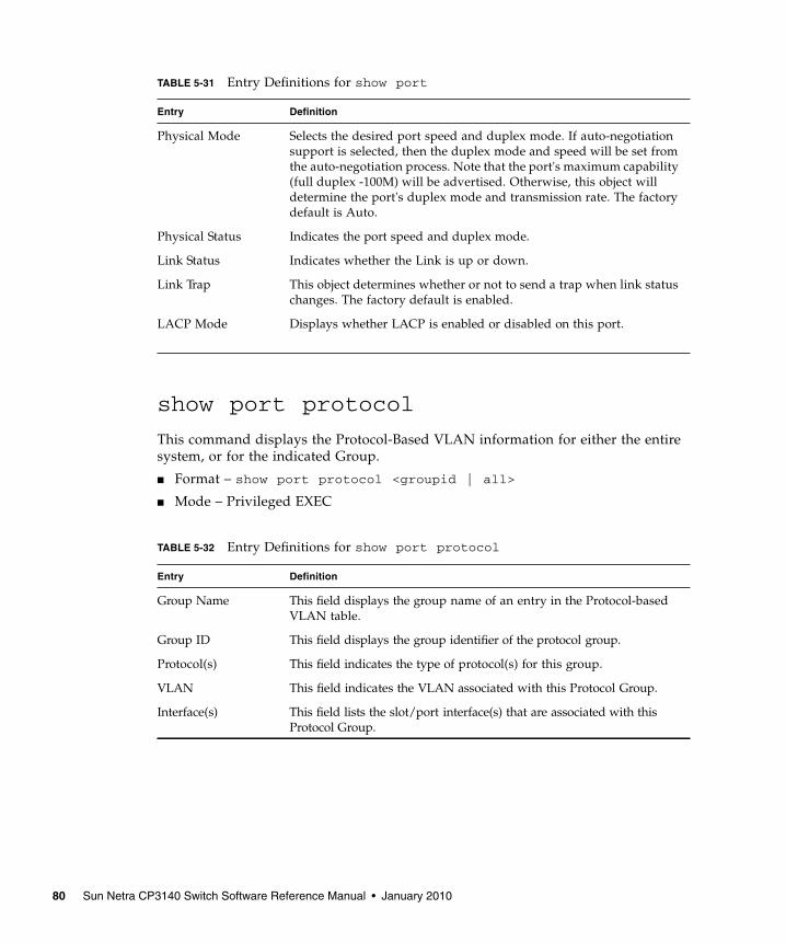
show port protocol
This command displays the Protocol-Based VLAN information for either the entiresystem, or for the indicated Group.
■ Format – show port protocol <groupid | all>
■ Mode – Privileged EXEC
Physical Mode Selects the desired port speed and duplex mode. If auto-negotiationsupport is selected, then the duplex mode and speed will be set fromthe auto-negotiation process. Note that the port's maximum capability(full duplex -100M) will be advertised. Otherwise, this object willdetermine the port's duplex mode and transmission rate. The factorydefault is Auto.
Physical Status Indicates the port speed and duplex mode.
Link Status Indicates whether the Link is up or down.
Link Trap This object determines whether or not to send a trap when link statuschanges. The factory default is enabled.
LACP Mode Displays whether LACP is enabled or disabled on this port.
TABLE 5-32 Entry Definitions for show port protocol
Entry Definition
Group Name This field displays the group name of an entry in the Protocol-basedVLAN table.
Group ID This field displays the group identifier of the protocol group.
Protocol(s) This field indicates the type of protocol(s) for this group.
VLAN This field indicates the VLAN associated with this Protocol Group.
Interface(s) This field lists the slot/port interface(s) that are associated with thisProtocol Group.
TABLE 5-31 Entry Definitions for show port
Entry Definition
80 Sun Netra CP3140 Switch Software Reference Manual • January 2010

show storm-control
This command displays switch configuration information.
■ Format – show storm-control
■ Mode – Privileged EXEC
Virtual LAN (VLAN) Commands
vlan
This command creates a new VLAN and assigns it an ID. The ID is a valid VLANidentification number (ID 1 is reserved for the default VLAN). VLAN range is2-4021.
■ Format – vlan <2-4021>
■ Mode – VLAN database
no vlan
This command deletes an existing VLAN. The ID is a valid VLAN identificationnumber (ID 1 is reserved for the default VLAN). VLAN range is 2-4021.
■ Format – no vlan <2-4021>
■ Mode – VLAN database
TABLE 5-33 Entry Definitions for show storm-control
Entry Definition
Broadcast StormRecovery Mode
May be enabled or disabled. The factory default is disabled.
802.3x Flow ControlMode
May be enabled or disabled. The factory default is disabled.
Chapter 5 Switching Commands 81
vlan acceptframe
This command sets the frame acceptance mode per interface. For VLAN Only mode,untagged frames or priority frames received on this interface are discarded. ForAdmit All mode, untagged frames or priority frames received on this interface areaccepted and assigned the value of the interface VLAN ID for this port. With eitheroption, VLAN tagged frames are forwarded in accordance with the IEEE 802.1QVLAN Specification.
■ Default – admit all
■ Format – vlan acceptframe <vlanonly | all>
■ Mode – Interface Config
no vlan acceptframe
This command sets the frame acceptance mode per interface to Admit All. ForAdmit All mode, untagged frames or priority frames received on this interface areaccepted and assigned the value of the interface VLAN ID for this port. With eitheroption, VLAN tagged frames are forwarded in accordance with the IEEE 802.1QVLAN Specification.
■ Format – vlan acceptframe <vlanonly | all>
■ Mode – Interface Config
vlan ingressfilter
This command enables ingress filtering. If ingress filtering is disabled, framesreceived with VLAN IDs that do not match the VLAN membership of the receivinginterface are admitted and forwarded to ports that are members of that VLAN.
■ Default – disabled
■ Format – vlan ingressfilter
■ Mode – Interface Config
no vlan ingressfilter
This command disables ingress filtering. If ingress filtering is disabled, framesreceived with VLAN IDs that do not match the VLAN membership of the receivinginterface are admitted and forwarded to ports that are members of that VLAN.
■ Format – no vlan ingressfilter
■ Mode – Interface Config
82 Sun Netra CP3140 Switch Software Reference Manual • January 2010
vlan makestatic
This command changes a dynamically created VLAN (one that is created by GVRPregistration) to a static VLAN (one that is permanently configured and defined). TheID is a valid VLAN identification number. VLAN range is 2-4021.
■ Format – vlan makestatic <2-4021>
■ Mode – VLAN database
vlan name
This command changes the name of a VLAN. The name is an alphanumeric string ofup to 32 characters, and the ID is a valid VLAN identification number. ID range is 1-4021.
■ Default – The name for VLAN ID 1 is always Default. The name for other VLANsis defaulted to a blank string.
■ Format – vlan name <2-4021> <name>
■ Mode – VLAN database
no vlan name
This command sets the name of a VLAN to a blank string. The VLAN ID is a vailidVLAN identification number. ID range is 1-4021.
■ Format – no vlan name <2-4021>
■ Mode – VLAN database
vlan participation
This command configures the degree of participation for a specific interface in aVLAN. The ID is a valid VLAN identification number, and the interface is a validinterface number.
■ Format – vlan participation <exclude | include | auto> <1-4021>
■ Mode – Interface Config
Participation options are as follows.
Chapter 5 Switching Commands 83

vlan participation all
This command configures the degree of participation for all interfaces in a VLAN.The ID is a valid VLAN identification number.
■ Format – vlan participation all <exclude | include | auto> <1-4021>
■ Mode – Global Config
Participation options are as follows.
TABLE 5-34 Entry Definitions for vlan participation
Entry Definition
include The interface is always a member of this VLAN. This is equivalent toregistration fixed.
exclude The interface is never a member of this VLAN. This is equivalent toregistration forbidden.
auto The interface is dynamically registered in this VLAN by GVRP. Theinterface will not participate in this VLAN unless a join request isreceived on this interface. This is equivalent to registration normal.
TABLE 5-35 Entry Definitions for vlan participation all
Entry Definition
include The interface is always a member of this VLAN. This is equivalent toregistration fixed.
exclude The interface is never a member of this VLAN. This is equivalent toregistration forbidden.
auto The interface is dynamically registered in this VLAN by GVRP. Theinterface will not participate in this VLAN unless a join request isreceived on this interface. This is equivalent to registration normal.
84 Sun Netra CP3140 Switch Software Reference Manual • January 2010
vlan port acceptframe all
This command sets the frame acceptance mode for all interfaces. For VLAN Onlymode, untagged frames or priority frames received on this interface are discarded.For Admit All mode, untagged frames or priority frames received on this interfaceare accepted and assigned the value of the interface VLAN ID for this port. Witheither option, VLAN tagged frames are forwarded in accordance with the IEEE802.1Q VLAN Specification.
■ Default – admit all
■ Format – vlan port acceptframe all <vlanonly | all>
■ Mode – Global Config
no vlan port acceptframe all
This command sets the frame acceptance mode for all interfaces to Admit All. ForAdmit All mode, untagged frames or priority frames received on this interface areaccepted and assigned the value of the interface VLAN ID for this port. With eitheroption, VLAN tagged frames are forwarded in accordance with the IEEE 802.1QVLAN Specification.
■ Format – no vlan port acceptframe all <vlanonly | all>
■ Mode – Global Config
vlan port ingressfilter all
This command enables ingress filtering for all ports. If ingress filtering is disabled,frames received with VLAN IDs that do not match the VLAN membership of thereceiving interface are admitted and forwarded to ports that are members of thatVLAN.
■ Default – disabled
■ Format – vlan port ingressfilter all
■ Mode – Global Config
Chapter 5 Switching Commands 85
no vlan port ingressfilter all
This command disables ingress filtering for all ports. If ingress filtering is disabled,frames received with VLAN IDs that do not match the VLAN membership of thereceiving interface are admitted and forwarded to ports that are members of thatVLAN.
■ Format – no vlan port ingressfilter all
■ Mode – Global Config
vlan port pvid all
This command changes the VLAN ID for all interfaces.
■ Default – 1
■ Format – vlan port pvid all <1-4021>
■ Mode – Global Config
no vlan port pvid all
This command sets the VLAN ID for all interfaces to 1.
■ Format – no vlan port pvid all <1-4021>
■ Mode – Global Config
vlan port tagging all
This command configures the tagging behavior for all interfaces in a VLAN toenabled. If tagging is enabled, traffic is transmitted as tagged frames. If tagging isdisabled, traffic is transmitted as untagged frames. The ID is a valid VLANidentification number.
■ Format – vlan port tagging all <1-4021>
■ Mode – Global Config
86 Sun Netra CP3140 Switch Software Reference Manual • January 2010

no vlan port tagging all
This command configures the tagging behavior for all interfaces in a VLAN todisabled. If tagging is disabled, traffic is transmitted as untagged frames. The ID is avalid VLAN identification number.
■ Format – no vlan port tagging all <1-4021>
■ Mode – Global Config
vlan protocol group
This command adds protocol-based VLAN group to the system. The <groupName>is a character string of 1 to 16 characters. When it is created, the protocol group willbe assigned a unique number that will be used to identify the group in subsequentcommands.
■ Format – vlan protocol group <groupname>
■ Mode – Global Config
vlan protocol group add protocol
This command adds the <protocol> to the protocol-based VLAN identified by<groupid>. A group may have more than one protocol associated with it. Eachinterface and protocol combination can only be associated with one group. If addinga protocol to a group causes any conflicts with interfaces currently associated withthe group, this command will fail and the protocol will not be added to the group.The possible values for protocol are ip, arp, and ipx.
■ Default – none
■ Format – vlan protocol group add protocol <groupid> <protocol>
■ Mode – Global Config
no vlan protocol group add protocol
This command removes the <protocol> from this protocol-based VLAN group that isidentified by this <groupid>. The possible values for protocol are ip, arp, and ipx.
■ Format – no vlan protocol group add protocol <groupid> <protocol>
■ Mode – Global Config
Chapter 5 Switching Commands 87

vlan protocol group remove
This command removes the protocol-based VLAN group that is identified by this<groupid>.
■ Format – vlan protocol group remove <groupid>
■ Mode – Global Config
protocol group
This command attaches a <vlanid> to the protocol-based VLAN identified by<groupid>. A group may only be associated with one VLAN at a time, however theVLAN association can be changed.
The referenced VLAN should be created prior to the creation of the protocol-basedVLAN except when GVRP is expected to create the VLAN.
■ Default – none
■ Format – protocol group <groupid> <vlanid>
■ Mode – VLAN database
no protocol group
This command removes the <vlanid> from this protocol-based VLAN group that isidentified by this <groupid>.
■ Format – no protocol group <groupid> <vlanid>
■ Mode – VLAN database
protocol vlan group
This command adds the physical <slot/port> interface to the protocol-based VLANidentified by <groupid>. A group may have more than one interface associated withit. Each interface and protocol combination can only be associated with one group. Ifadding an interface to a group causes any conflicts with protocols currentlyassociated with the group, this command will fail and the interface(s) will not beadded to the group.
88 Sun Netra CP3140 Switch Software Reference Manual • January 2010

The referenced VLAN should be created prior to the creation of the protocol-basedVLAN except when GVRP is expected to create the VLAN.
■ Default – none
■ Format – protocol vlan group <groupid>
■ Mode – Interface Config
no protocol vlan group
This command removes the <interface> from this protocol-based VLAN group that isidentified by this <groupid>. If <all> is selected, all ports will be removed from thisprotocol group.
■ Format – no protocol vlan group <groupid>
■ Mode – Interface Config
protocol vlan group all
This command adds all physical interfaces to the protocol-based VLAN identified by<groupid>. A group may have more than one interface associated with it. Eachinterface and protocol combination can only be associated with one group. If addingan interface to a group causes any conflicts with protocols currently associated withthe group, this command will fail and the interface(s) will not be added to the group.
The referenced VLAN should be created prior to the creation of the protocol-basedVLAN except when GVRP is expected to create the VLAN.
■ Default – none
■ Format – protocol vlan group all <groupid>
■ Mode – Global Config
no protocol vlan group all
This command removes all interfaces from this protocol-based VLAN group that isidentified by this <groupid>.
■ Format – no protocol vlan group all <groupid>
■ Mode – Global Config
Chapter 5 Switching Commands 89
vlan pvid
This command changes the VLAN ID per interface.
■ Default – 1
■ Format – vlan pvid <1-4021>
■ Mode – Interface Config
no vlan pvid
This command sets the VLAN ID per interface to 1.
■ Format – no vlan pvid <1-4021>
■ Mode – Interface Config
vlan tagging
This command configures the tagging behavior for a specific interface in a VLAN toenabled. If tagging is enabled, traffic is transmitted as tagged frames. If tagging isdisabled, traffic is transmitted as untagged frames. The ID is a valid VLANidentification number.
■ Format – vlan tagging <1-4021>
■ Mode – Interface Config
no vlan tagging
This command configures the tagging behavior for a specific interface in a VLAN todisabled. If tagging is disabled, traffic is transmitted as untagged frames. The ID is avalid VLAN identification number.
■ Format – no vlan tagging <1-4021>
■ Mode – Interface Config
show vlan
This command displays detailed information, including interface information, for aspecific VLAN. The ID is a valid VLAN identification number.
■ Format – show vlan <vlanid>
■ Mode – Privileged EXEC and User EXEC
90 Sun Netra CP3140 Switch Software Reference Manual • January 2010
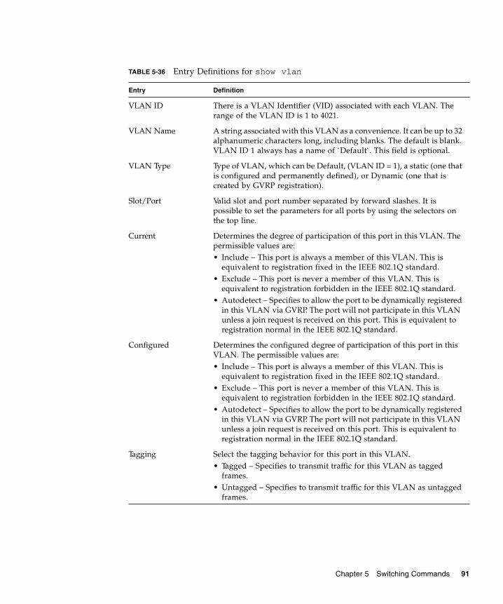
TABLE 5-36 Entry Definitions for show vlan
Entry Definition
VLAN ID There is a VLAN Identifier (VID) associated with each VLAN. Therange of the VLAN ID is 1 to 4021.
VLAN Name A string associated with this VLAN as a convenience. It can be up to 32alphanumeric characters long, including blanks. The default is blank.VLAN ID 1 always has a name of `Default`. This field is optional.
VLAN Type Type of VLAN, which can be Default, (VLAN ID = 1), a static (one thatis configured and permanently defined), or Dynamic (one that iscreated by GVRP registration).
Slot/Port Valid slot and port number separated by forward slashes. It ispossible to set the parameters for all ports by using the selectors onthe top line.
Current Determines the degree of participation of this port in this VLAN. Thepermissible values are:• Include – This port is always a member of this VLAN. This is
equivalent to registration fixed in the IEEE 802.1Q standard.• Exclude – This port is never a member of this VLAN. This is
equivalent to registration forbidden in the IEEE 802.1Q standard.• Autodetect – Specifies to allow the port to be dynamically registered
in this VLAN via GVRP. The port will not participate in this VLANunless a join request is received on this port. This is equivalent toregistration normal in the IEEE 802.1Q standard.
Configured Determines the configured degree of participation of this port in thisVLAN. The permissible values are:• Include – This port is always a member of this VLAN. This is
equivalent to registration fixed in the IEEE 802.1Q standard.• Exclude – This port is never a member of this VLAN. This is
equivalent to registration forbidden in the IEEE 802.1Q standard.• Autodetect – Specifies to allow the port to be dynamically registered
in this VLAN via GVRP. The port will not participate in this VLANunless a join request is received on this port. This is equivalent toregistration normal in the IEEE 802.1Q standard.
Tagging Select the tagging behavior for this port in this VLAN.• Tagged – Specifies to transmit traffic for this VLAN as tagged
frames.• Untagged – Specifies to transmit traffic for this VLAN as untagged
frames.
Chapter 5 Switching Commands 91
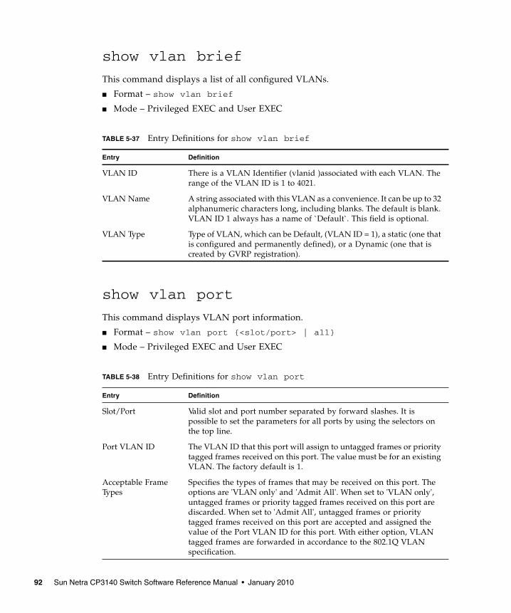
show vlan brief
This command displays a list of all configured VLANs.
■ Format – show vlan brief
■ Mode – Privileged EXEC and User EXEC
show vlan port
This command displays VLAN port information.
■ Format – show vlan port {<slot/port> | all}
■ Mode – Privileged EXEC and User EXEC
TABLE 5-37 Entry Definitions for show vlan brief
Entry Definition
VLAN ID There is a VLAN Identifier (vlanid )associated with each VLAN. Therange of the VLAN ID is 1 to 4021.
VLAN Name A string associated with this VLAN as a convenience. It can be up to 32alphanumeric characters long, including blanks. The default is blank.VLAN ID 1 always has a name of `Default`. This field is optional.
VLAN Type Type of VLAN, which can be Default, (VLAN ID = 1), a static (one thatis configured and permanently defined), or a Dynamic (one that iscreated by GVRP registration).
TABLE 5-38 Entry Definitions for show vlan port
Entry Definition
Slot/Port Valid slot and port number separated by forward slashes. It ispossible to set the parameters for all ports by using the selectors onthe top line.
Port VLAN ID The VLAN ID that this port will assign to untagged frames or prioritytagged frames received on this port. The value must be for an existingVLAN. The factory default is 1.
Acceptable FrameTypes
Specifies the types of frames that may be received on this port. Theoptions are 'VLAN only' and 'Admit All'. When set to 'VLAN only',untagged frames or priority tagged frames received on this port arediscarded. When set to 'Admit All', untagged frames or prioritytagged frames received on this port are accepted and assigned thevalue of the Port VLAN ID for this port. With either option, VLANtagged frames are forwarded in accordance to the 802.1Q VLANspecification.
92 Sun Netra CP3140 Switch Software Reference Manual • January 2010

System Utility CommandsThis section describes system utilities. The commands are divided into twofunctional groups:
■ Show commands display switch settings, statistics, and other information.
■ Configuration commands configure features and options of the switch. For everyconfiguration command, there is a show command that displays the configurationsetting.
clear config
This command resets the configuration to the factory defaults without powering offthe switch. The switch is automatically reset when this command is processed. Youare prompted to confirm that the reset should proceed.
■ Format – clear config
■ Mode – Privileged EXEC
clear counters
This command clears the stats for a specified <slot/port>or for all the ports or forthe entire switch based upon the argument.
■ Format – clear counters {<slot/port> | all}
■ Mode – Privileged EXEC
Ingress Filtering May be enabled or disabled. When enabled, the frame is discarded ifthis port is not a member of the VLAN with which this frame isassociated. In a tagged frame, the VLAN is identified by the VLAN IDin the tag. In an untagged frame, the VLAN is the Port VLAN IDspecified for the port that received this frame. When disabled, allframes are forwarded in accordance with the 802.1Q VLAN bridgespecification. The factory default is disabled.
GVRP May be enabled or disabled.
Default Priority The 802.1p priority assigned to tagged packets arriving on the port.
TABLE 5-38 Entry Definitions for show vlan port
Entry Definition
Chapter 5 Switching Commands 93

clear igmpsnooping
This command clears the tables managed by the IGMP Snooping function and willattempt to delete these entries from the Multicast Forwarding Database.
■ Format – clear igmpsnooping
■ Mode – Privileged EXEC
clear pass
This command resets all user passwords to the factory defaults without powering offthe switch. You are prompted to confirm that the password reset should proceed.
■ Format – clear pass
■ Mode – Privileged EXEC
enable passwd
This command changes the Privileged EXEC password. First type the command thenhit the enter or the return key.
■ Format – enable passwd
■ Mode – Privileged EXEC
clear port-channel
This command clears all port-channels (LAGs).
■ Format – clear port-channel
■ Mode – Privileged EXEC
clear traplog
This command clears the trap log.
■ Format – clear traplog
■ Mode – Privileged EXEC
94 Sun Netra CP3140 Switch Software Reference Manual • January 2010

clear vlan
This command resets VLAN configuration parameters to the factory defaults.
■ Format – clear vlan
■ Mode – Privileged EXEC
logout
This command closes the current telnet connection or resets the current serialconnection.
Note – Save configuration changes before logging out.
■ Format – logout
■ Mode – Privileged EXEC
ping
This command checks if another computer is on the network and listens forconnections. To use this command, configure the switch for network (in-band)connection. The source and target devices must have the ping utility enabled andrunning on top of TCP/IP. The switch can be pinged from any IP workstation withwhich the switch is connected through the default VLAN (VLAN 1), as long as thereis a physical path between the switch and the workstation. The terminal interfacesends, three pings to the target station.
■ Format – ping <ipaddr>
■ Mode – Privileged EXEC and User EXEC
reload
This command resets the switch without powering it off. Reset means that allnetwork connections are terminated and the boot code executes. The switch uses thestored configuration to initialize the switch. You are prompted to confirm that thereset should proceed. A successful reset is indicated by the LEDs on the switch.
■ Format – reload
■ Mode – Privileged EXEC
Chapter 5 Switching Commands 95

copy
This command uploads and downloads to/from the switch. Local URLs can bespecified using tftp or xmodem. The following can be specified as the source file foruploading from the switch: startup configuration (nvram:startup-config), errorlog (nvram:errorlog), message log (nvram:msglog) and trap log(nvram:traplog). A URL is specified for the destination.
The command can also be used to download the startup configuration or code imageby specifying the source as a URL and destination as nvram:startup-config or.system:image respectively.
The command can be used to the save the running configuration to nvram byspecifying the source as system:running-config and the destination asnvram:startup-config. The command can also be used to download SSH keyfiles as nvram:sshkey-rsa, nvram:sshkey-rsa2, and nvram:sshkey-dsa andhttp secure-server certificates as nvram:sslpem-root, nvram:sslpem-server,nvram:sslpem-dhweak, and nvram:sslpem-dhstrong.
■ Default – none
■ Format:
■ copy nvram:startup-config <url>
■ copy nvram:errorlog <url>
■ copy nvram:msglog <url>
■ copy nvram:traplog <url>
■ copy <url> nvram:startup-config
■ copy <url> system:image
■ copy system:running-config nvram:startup-config
■ copy <url> nvram:sslpem-root
■ copy <url> nvram:sslpem-server
■ copy <url> nvram:sslpem-dhweak
■ copy <url> nvram:sslpem-dhstrong
■ copy <url> nvram:sshkey-rsa1
■ copy <url> nvram:sshkey-rsa2
■ copy <url> nvram:sshkey-dsa
■ Mode – Privileged EXEC
96 Sun Netra CP3140 Switch Software Reference Manual • January 2010

User Account CommandsThese commands manage user accounts. The commands are divided into twofunctional groups:
■ Show commands display switch settings, statistics, and other information.
■ Configuration commands configure features and options of the switch. For everyconfiguration command, there is a show command that displays the configurationsetting.
disconnect
This command closes a telnet session.
■ Format – disconnect {<sessionID> | all}
■ Mode – Privileged EXEC
show loginsession
This command displays current telnet and serial port connections to the switch.
■ Format – show loginsession
■ Mode – Privileged EXEC
TABLE 5-39 Entry Definitions for show loginsession
Entry Definition
ID Login Session ID
User Name The name the user will use to login using the serial port or Telnet. Anew user may be added to the switch by entering a name in a blankentry. The user name may be up to 8 characters, and is not casesensitive. Two users are included as the factory default, ‘admin’ and‘guest’.
Connection From IP address of the telnet client machine or EIA-232 for the serial portconnection.
Idle Time Time this session has been idle.
Session Time Total time this session has been connected.
Chapter 5 Switching Commands 97

show users
This command displays the configured user names and their settings. This commandis only available for users with Read/Write privileges. The SNMPv3 fields will onlybe displayed if SNMP is available on the system.
■ Format – show users
■ Mode – Privileged EXEC
users name
This command adds a new user (account) if space permits. The account <username> canbe up to eight characters in length. The name may be comprised of alphanumericcharacters as well as the dash (‘-’) and underscore (‘_’). The <username> is not case-sensitive.
Six user names can be defined.
■ Format – users name <username>
■ Mode – Global Config
TABLE 5-40 Entry Definitions for show users
Entry Description
User Name The name the user will use to login using the serial port, Telnet orWeb. A new user may be added to the switch by entering a name in ablank entry. The user name may be up to eight characters, and is notcase sensitive. Two users are included as the factory default, ‘admin’and ‘guest’
Access Mode Shows whether the operator is able to change parameters on theswitch (Read/Write) or is only able to view them (Read Only). As afactory default, the ‘admin’ user has Read/Write access and the‘guest’ has Read Only access. There can only be one Read/ Write userand up to five Read Only users.
SNMPv3 AccessMode
This field displays the SNMPv3 Access Mode. If the value is set toRead-Write, the SNMPv3 user will be able to set and retrieveparameters on the system. If the value is set to ReadOnly, theSNMPv3 user will only be able to retrieve parameter information. TheSNMPv3 access mode may be different than the CLI and Web accessmode.
SNMPv3Authentication
This field displays the authentication protocol to be used for thespecified login user.
SNMPv3 Encryption This field displays the encryption protocol to be used for the specifiedlogin user.
98 Sun Netra CP3140 Switch Software Reference Manual • January 2010

no users name
This command removes an operator.
■ Format – no users name <username>
■ Mode – Global Config
Note – The ‘admin’ user account cannot be deleted.
users passwd
This command is used to change a password. The password should not be morethan eight alphanumeric characters in length. If a user is authorized forauthentication or encryption is enabled, the password must be at least eightalphanumeric characters in length. The username and password are not case-sensitive. When a password is changed, a prompt will ask for the former password.If none, press enter.
■ Default – no password
■ Format – users passwd <username>
■ Mode – Global Config
no users passwd
This command sets the password of an existing operator to blank. When a passwordis changed, a prompt will ask for the operator's former password. If none, pressenter.
■ Format – no users passwd <username>
■ Mode – Global Config
users snmpv3 accessmode
This command specifies the snmpv3 access privileges for the specified login user.The valid accessmode values are readonly or readwrite. The <username> is the loginuser name for which the specified access mode applies. The default is readwrite for‘admin’ user; readonly for all other users
■ Default:
■ admin – readwrite
■ other – readonly
Chapter 5 Switching Commands 99

■ Format – users snmpv3 accessmode <username> <readonly |readwrite>
■ Mode – Global Config
no users snmpv3 accessmode
This command sets the snmpv3 access privileges for the specified login user asreadwrite for the ‘admin’ user; readonly for all other users. The <username> is thelogin user name for which the specified access mode will apply.
■ Format – no users snmpv3 accessmode <username>
■ Mode – Global Config
users snmpv3 authentication
This command specifies the authentication protocol to be used for the specified loginuser. The valid authentication protocols are none, md5 or sha. If md5 or sha arespecified, the user login password is also used as the snmpv3 authenticationpassword and therefore must be at least eight characters in length. The <username>is the login user name associated with the authentication protocol.
■ Default – no authentication
■ Format – users snmpv3 authentication <username> <none | md5 |sha>
■ Mode – Global Config
no users snmpv3 authentication
This command sets the authentication protocol to be used for the specified login userto none. The <username> is the login user name for which the specifiedauthentication protocol will be used.
■ Format – users snmpv3 authentication <username>
■ Mode – Global Config
users snmpv3 encryption
This command specifies the encryption protocol to be used for the specified loginuser. The valid encryption protocols are des or none.
100 Sun Netra CP3140 Switch Software Reference Manual • January 2010

If des is specified, the required key may be specified on the command line. Theencryption key must be 8 to 64 characters long. If the des protocol is specified but akey is not provided, the user will be prompted for the key. When using the desprotocol, the user login password is also used as the snmpv3 encryption passwordand therefore must be at least eight characters in length.
If none is specified, a key must not be provided. The <username> is the login username associated with the specified encryption.
■ Default – no encryption
■ Format – users snmpv3 encryption <username> <none | des[key]>
■ Mode – Global Config
no users snmpv3 encryption
This command sets the encryption protocol to none. The <username> is the loginuser name for which the specified encryption protocol will be used.
■ Format – no users snmpv3 encryption <username>
■ Mode – Global Config
Port Based Network Access Control(IEEE 802.1X) CommandsThis section provides a detailed explanation of the 802.1x commands. Thecommands are divided into the following groups:
■ Configuration commands are used to configure features and options of theswitch. For every configuration command there is a show command that willdisplay the configuration setting.
■ Show commands are used to display switch settings, statistics and otherinformation.
Chapter 5 Switching Commands 101
authentication login
This command creates an authentication login list. The <listname> is up to 15alphanumeric characters and is not case sensitive. Up to 10 authentication login listscan be configured on the switch. When a list is created, the authentication method“local” is set as the first method.
When the optional parameters “Option1”, “Option2” and/or “Option3” are used, anordered list of methods are set in the authentication login list. If the authenticationlogin list does not exist, a new authentication login list is first created and then theauthentication methods are set in the authentication login list. The maximumnumber of authentication login methods is three. The possible method values arelocal, radius and reject.
The value of local indicates that the user’s locally stored ID and password are usedfor authentication. The value of radius indicates that the user’s ID and passwordwill be authenticated using the RADIUS server. The value of reject indicates theuser is never authenticated.
To authenticate a user, the authentication methods in the user’s login will beattempted in order until an authentication attempt succeeds or fails.
Note – The default login list included with the default configuration can not bechanged.
■ Format – authentication login <listname> [method1 [method2[method3]]]
■ Mode – Global Config
no authentication login
This command deletes the specified authentication login list. The attempt to deletewill fail if any of the following conditions are true:
■ The login list name is invalid or does not match an existing authentication loginlist
■ The specified authentication login list is assigned to any user or to the nonconfigured user for any component
■ The login list is the default login list included with the default configuration and wasnot created using ‘authentication login’. The default login list cannot be deleted.
102 Sun Netra CP3140 Switch Software Reference Manual • January 2010
Following are the format and mode for the no authentication logincommand:
■ Format – no authentication login <listname>
■ Mode – Global Config
clear dot1x statistics
This command resets the 802.1x statistics for the specified port or for all ports.
■ Format – clear dot1x statistics { <slot/port> | all }
■ Mode – Privileged EXEC
clear radius statistics
This command is used to clear all RADIUS statistics.
■ Format – clear radius statistics
■ Mode – Privileged EXEC
dot1x defaultlogin
This command assigns the authentication login list to use for non-configured usersfor 802.1x port security. This setting is over-ridden by the authentication login listassigned to a specific user if the user is configured locally. If this value is notconfigured, users will be authenticated using local authentication only.
■ Format – dot1x defaultlogin <listname>
■ Mode – Global Config
dot1x initialize
This command begins the initialization sequence on the specified port. Thiscommand is only valid if the control mode for the specified port is 'auto'. If thecontrol mode is not 'auto' an error will be returned.
■ Format – dot1x initialize <slot/port>
■ Mode – Privileged EXEC
Chapter 5 Switching Commands 103

dot1x login
This command assigns the specified authentication login list to the specified user for802.1x port security. The <user> parameter must be a configured user and the<listname> parameter must be a configured authentication login list.
■ Format – dot1x login <user> <listname>
■ Mode – Global Config
dot1x max-req
This command sets the maximum number of times the authenticator state machineon this port will transmit an EAPOL EAP Request/Identity frame before timing outthe supplicant. The <count> value must be in the range 1-10.
■ Default – 2
■ Format – dot1x max-req <count>
■ Mode – Interface Config
no dot1x max-req
This command sets the maximum number of times the authenticator state machineon this port will transmit an EAPOL EAP Request/Identity frame before timing outthe supplicant.
■ Format – no dot1x max-req
■ Mode – Interface Config
dot1x port-control
This command sets the authentication mode to be used on the specified port. Thecontrol mode may be one of the following:
■ force-unauthorized: The authenticator PAE unconditionally sets the controlledport to unauthorized.
■ force-authorized: The authenticator PAE unconditionally sets the controlled portto authorized.
■ auto: The authenticator PAE sets the controlled port mode to reflect the outcomeof the authentication exchanges between the supplicant, authenticator and theauthentication server.
104 Sun Netra CP3140 Switch Software Reference Manual • January 2010

Following are the format and mode for the dot1x port-control command.
■ Default – auto
■ Format – dot1x port-control {force-unauthorized | force-authorized | auto}
■ Mode – Interface Config
no dot1x port-control
This command sets the authentication mode to be used on the specified port to'auto'.
■ Format – no dot1x port-control
■ Mode – Interface Config
dot1x port-control All
This command sets the authentication mode to be used on all ports. The controlmode may be one of the following.
■ force-unauthorized: The authenticator PAE unconditionally sets the controlledport to unauthorized.
■ force-authorized: The authenticator PAE unconditionally sets the controlled portto authorized.
■ auto: The authenticator PAE sets the controlled port mode to reflect the outcomeof the authentication exchanges between the supplicant, authenticator and theauthentication server.
Following are the format and mode for the dot1x port-control All command.
■ Default – auto
■ Format – dot1x port-control all {force-unauthorized | force-authorized | auto}
■ Mode – Global Config
no dot1x port-control All
This command sets the authentication mode to be used on all ports to 'auto'.
■ Format – no dot1x port-control all
■ Mode – Global Config
Chapter 5 Switching Commands 105
dot1x re-authenticate
This command begins the re-authentication sequence on the specified port. Thiscommand is only valid if the control mode for the specified port is 'auto'. If thecontrol mode is not 'auto' an error will be returned.
■ Format – dot1x re-authenticate <slot/port>
■ Mode – Privileged EXEC
dot1x re-authentication
This command enables re-authentication of the supplicant for the specified port.
■ Default – disabled
■ Format – dot1x re-authentication
■ Mode – Interface Config
no dot1x re-authentication
This command disables re-authentication of the supplicant for the specified port.
■ Format – no dot1x re-authentication
■ Mode – Interface Config
dot1x system-auth-control
This command is used to enable the dot1x authentication support on the switch. Bydefault, the authentication support is disabled. While disabled, the dot1xconfiguration is retained and can be changed, but is not activated.
■ Default – disabled
■ Format – dot1x system-auth-control
■ Mode – Global Config
no dot1x system-auth-control
This command is used to disable the dot1x authentication support on the switch.
■ Format – no dot1x system-auth-control
■ Mode – Global Config
106 Sun Netra CP3140 Switch Software Reference Manual • January 2010
dot1x timeout
This command sets the value, in seconds, of the timer used by the authenticator statemachine on this port. Depending on the token used and the value (in seconds)passed, various timeout configurable parameters are set. The following tokens aresupported.
■ reauth-period: Sets the value, in seconds, of the timer used by the authenticatorstate machine on this port to determine when re-authentication of the supplicanttakes place. The reauth-period must be a value in the range 1 - 65535.
■ quiet-period: Sets the value, in seconds, of the timer used by the authenticatorstate machine on this port to define periods of time in which it will not attempt toacquire a supplicant. The quiet-period must be a value in the range 0 - 65535.
■ tx-period: Sets the value, in seconds, of the timer used by the authenticator statemachine on this port to determine when to send an EAPOL EAP Request/Identityframe to the supplicant. The quiet-period must be a value in the range 1 - 65535.
■ supp-timeout: Sets the value, in seconds, of the timer used by the authenticatorstate machine on this port to timeout the supplicant. The supp-timeout must be avalue in the range 1 - 65535.
■ server-timeout: Sets the value, in seconds, of the timer used by the authenticatorstate machine on this port to timeout the authentication server. The supp-timeoutmust be a value in the range 1 - 65535.
Following are the format and mode for the dot1x timeout command.
■ Defaults:
■ reauth-period: 3600 seconds
■ quiet-period: 60 seconds
■ tx-period: 30 seconds
■ supp-timeout: 30 seconds
■ server-timeout: 30 seconds
■ Format – dot1x timeout {{reauth-period <seconds>} | {quiet-period<seconds>} | {tx-period <seconds>} | {supp-timeout <seconds>} |{server-timeout <seconds>}}
■ Mode – Interface Config
Chapter 5 Switching Commands 107
no dot1x timeout
This command sets the value, in seconds, of the timer used by the authenticator statemachine on this port to the default values. Depending on the token used, thecorresponding default values are set.
■ Format – no dot1x timeout {reauth-period | quiet-period | tx-period | supp-timeout | server-timeout}
■ Mode – Interface Config
dot1x user
This command adds the specified user to the list of users with access to the specifiedport or all ports. The <user> parameter must be a configured user.
■ Format – dot1x user <user> {<slot/port> | all}
■ Mode – Global Config
no dot1x user
This command removes the user from the list of users with access to the specifiedport or all ports.
■ Format – no dot1x user <user> {<slot/port> | all}
■ Mode – Global Config
show radius accounting
This command is used to display the configured RADIUS accounting mode,accounting server and the statistics for the configured accounting server.
■ Format – show radius accounting [statistics <ipaddr>]
■ Mode – Privileged EXEC
If the optional token statistics <ipaddr> is not included, then only theaccounting mode and the RADIUS accounting server details are displayed.
108 Sun Netra CP3140 Switch Software Reference Manual • January 2010
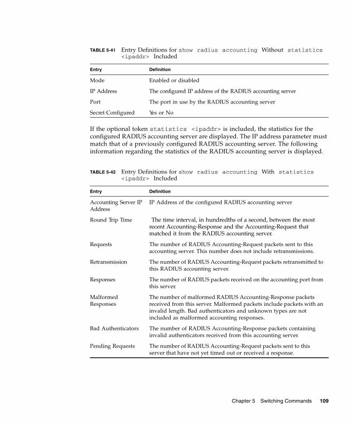
If the optional token statistics <ipaddr> is included, the statistics for theconfigured RADIUS accounting server are displayed. The IP address parameter mustmatch that of a previously configured RADIUS accounting server. The followinginformation regarding the statistics of the RADIUS accounting server is displayed.
TABLE 5-41 Entry Definitions for show radius accounting Without statistics<ipaddr> Included
Entry Definition
Mode Enabled or disabled
IP Address The configured IP address of the RADIUS accounting server
Port The port in use by the RADIUS accounting server
Secret Configured Yes or No
TABLE 5-42 Entry Definitions for show radius accounting With statistics<ipaddr> Included
Entry Definition
Accounting Server IPAddress
IP Address of the configured RADIUS accounting server
Round Trip Time The time interval, in hundredths of a second, between the mostrecent Accounting-Response and the Accounting-Request thatmatched it from the RADIUS accounting server.
Requests The number of RADIUS Accounting-Request packets sent to thisaccounting server. This number does not include retransmissions.
Retransmission The number of RADIUS Accounting-Request packets retransmitted tothis RADIUS accounting server.
Responses The number of RADIUS packets received on the accounting port fromthis server.
MalformedResponses
The number of malformed RADIUS Accounting-Response packetsreceived from this server. Malformed packets include packets with aninvalid length. Bad authenticators and unknown types are notincluded as malformed accounting responses.
Bad Authenticators The number of RADIUS Accounting-Response packets containinginvalid authenticators received from this accounting server.
Pending Requests The number of RADIUS Accounting-Request packets sent to thisserver that have not yet timed out or received a response.
Chapter 5 Switching Commands 109

show authentication
This command displays the ordered authentication methods for all authenticationlogin lists.
■ Format – show authentication
■ Mode – Privileged EXEC
show authentication users
This command displays information about the users assigned to the specifiedauthentication login list. If the login is assigned to non-configured users, the user“default” will appear in the user column.
■ Format – show authentication users <listname>
■ Mode – Privileged EXEC
Timeouts The number of accounting timeouts to this server.
Unknown Types The number of RADIUS packets of unknown types, which werereceived from this server on the accounting port.
Packets Dropped The number of RADIUS packets received from this server on theaccounting port and dropped for some other reason.
TABLE 5-43 Entry Definitions for show authentication
Entry Definition
Authentication LoginList
This displays the authentication login listname.
Method 1 This displays the first method in the specified authentication login list, ifany.
Method 2 This displays the second method in the specified authentication loginlist, if any.
Method 3 This displays the third method in the specified authentication loginlist, if any.
TABLE 5-42 Entry Definitions for show radius accounting With statistics<ipaddr> Included
Entry Definition
110 Sun Netra CP3140 Switch Software Reference Manual • January 2010

show dot1x
This command is used to show a summary of the global dot1x configuration,summary information of the dot1x configuration for a specified port or all ports, thedetailed dot1x configuration for a specified port and the dot1x statistics for aspecified port depending on the tokens used.
■ Format – show dot1x [{summary {<slot/port> | all} | {detail<slot/port>} | {statistics <slot/port>}]
■ Mode – Privileged EXEC
If none of the optional parameters are used, the global dot1x configuration summaryis displayed.
If the optional parameter summary {<slot/port> | all} is used, the dot1xconfiguration for the specified port or all ports are displayed.
TABLE 5-44 Entry Definitions for show authentication users
Entry Definition
User This field displays the user assigned to the specified authenticationlogin list.
Component This field displays the component (User or 802.1x) for which theauthentication login list is assigned.
TABLE 5-45 Entry Definitions for show dot1x Without Optional Parameters
Entry Definition
Administrative mode Indicates whether authentication control on the switch is enabled ordisabled.
Chapter 5 Switching Commands 111

If the optional parameter detail <slot/port> is used, the detailed dot1xconfiguration for the specified port are displayed.
TABLE 5-46 Entry Definitions for show dot1x With summary {<slot/port> | all}Parameter Used
Entry Definition
Port The interface whose configuration is displayed.
Control Mode The configured control mode for this port. Possible values are:• force-unauthorized• force-authorized• auto
Operating ControlMode
The control mode under which this port is operating. Possible valuesare:• authorized• unauthorized
ReauthenticationEnabled
Indicates whether re-authentication is enabled on this port
Key TransmissionEnabled
Indicates if the key is transmitted to the supplicant for the specifiedport
TABLE 5-47 Entry Definitions for show dot1x With detail <slot/port> ParameterUsed
Entry Definition
Port The interface whose configuration is displayed
Protocol Version The protocol version associated with this port. The only possible valueis 1, corresponding to the first version of the dot1x specification.
PAE Capabilities The port access entity (PAE) functionality of this port. Possible valuesare:• Authenticator• Supplicant
112 Sun Netra CP3140 Switch Software Reference Manual • January 2010

Authenticator PAEState
Current state of the authenticator PAE state machine. Possible valuesare:• Initialize• Disconnected• Connecting• Authenticating• Authenticated• Aborting• Held• ForceAuthorized• ForceUnauthorized
BackendAuthentication State
Current state of the backend authentication state machine. Possiblevalues are:• Request• Response• Success• Fail• Timeout• Idle• Initialize.
Quiet Period The timer used by the authenticator state machine on this port todefine periods of time in which it will not attempt to acquire asupplicant. The value is expressed in seconds and will be in the range 0and 65535.
Transmit Period The timer used by the authenticator state machine on the specified portto determine when to send an EAPOL EAP Request/Identity frame tothe supplicant. The value is expressed in seconds and will be in therange of 1 and 65535.
Supplicant Timeout The timer used by the authenticator state machine on this port totimeout the supplicant. The value is expressed in seconds and will bein the range of 1 and 65535.
Server Timeout The timer used by the authenticator on this port to timeout theauthentication server. The value is expressed in seconds and will be inthe range of 1 and 65535.
Maximum Requests The maximum number of times the authenticator state machine on thisport will retransmit an EAPOL EAP Request/Identity before timing outthe supplicant. The value will be in the range of 1 and 10.
TABLE 5-47 Entry Definitions for show dot1x With detail <slot/port> ParameterUsed
Entry Definition
Chapter 5 Switching Commands 113

If the optional parameter statistics <slot/port> is used, the dot1x statisticsfor the specified port are displayed.
ReauthenticationPeriod
The timer used by the authenticator state machine on this port todetermine when reauthentication of the supplicant takes place. Thevalue is expressed in seconds and will be in the range of 1 and 65535.
ReauthenticationEnabled
Indicates if reauthentication is enabled on this port. Possible values are:• True• False
Key TransmissionEnabled
Indicates if the key is transmitted to the supplicant for the specified port.Possible values are:• True• False.
Control Direction Indicates the control direction for the specified port or ports. Possiblevalues are both or in.
TABLE 5-48 Entry Definitions for show dot1x With statistics <slot/port>Parameter Used
Entry Definition
Port The interface whose statistics are displayed.
EAPOL FramesReceived
The number of valid EAPOL frames of any type that have been receivedby this authenticator.
EAPOL FramesTransmitted
The number of EAPOL frames of any type that have been transmittedby this authenticator.
EAPOL Start FramesReceived
The number of EAPOL start frames that have been received by thisauthenticator.
EAPOL LogoffFrames Received
The number of EAPOL logoff frames that have been received by thisauthenticator.
Last EAPOL FrameVersion
The protocol version number carried in the most recently receivedEAPOL frame.
Last EAPOL FrameSource
The source MAC address carried in the most recently received EAPOLframe.
EAP Response/IdFrames Received
The number of EAP response/identity frames that have been receivedby this authenticator.
EAP Response FramesReceived
The number of valid EAP response frames (other than resp/idframes) that have been received by this authenticator.
TABLE 5-47 Entry Definitions for show dot1x With detail <slot/port> ParameterUsed
Entry Definition
114 Sun Netra CP3140 Switch Software Reference Manual • January 2010

show dot1x users
This command displays 802.1x port security user information for locally configuredusers.
■ Format – show dot1x users <slot/port>
■ Mode – Privileged EXEC
show users authentication
This command displays all user and all authentication login information. It alsodisplays the authentication login list assigned to the default user.
■ Format – show users authentication
■ Mode – Privileged EXEC
EAP Request/IdFrames Transmitted
The number of EAP request/identity frames that have beentransmitted by this authenticator.
EAP Request FramesTransmitted
The number of EAP request frames (other than request/identityframes) that have been transmitted by this authenticator.
Invalid EAPOLFrames Received
The number of EAPOL frames that have been received by thisauthenticator in which the frame type is not recognized.
EAP Length ErrorFrames Received
The number of EAPOL frames that have been received by thisauthenticator in which the frame type is not recognized.
TABLE 5-49 Entry Definitions for show dot1x users
Entry Definition
User Users configured locally to have access to the specified port.
TABLE 5-48 Entry Definitions for show dot1x With statistics <slot/port>Parameter Used
Entry Definition
Chapter 5 Switching Commands 115
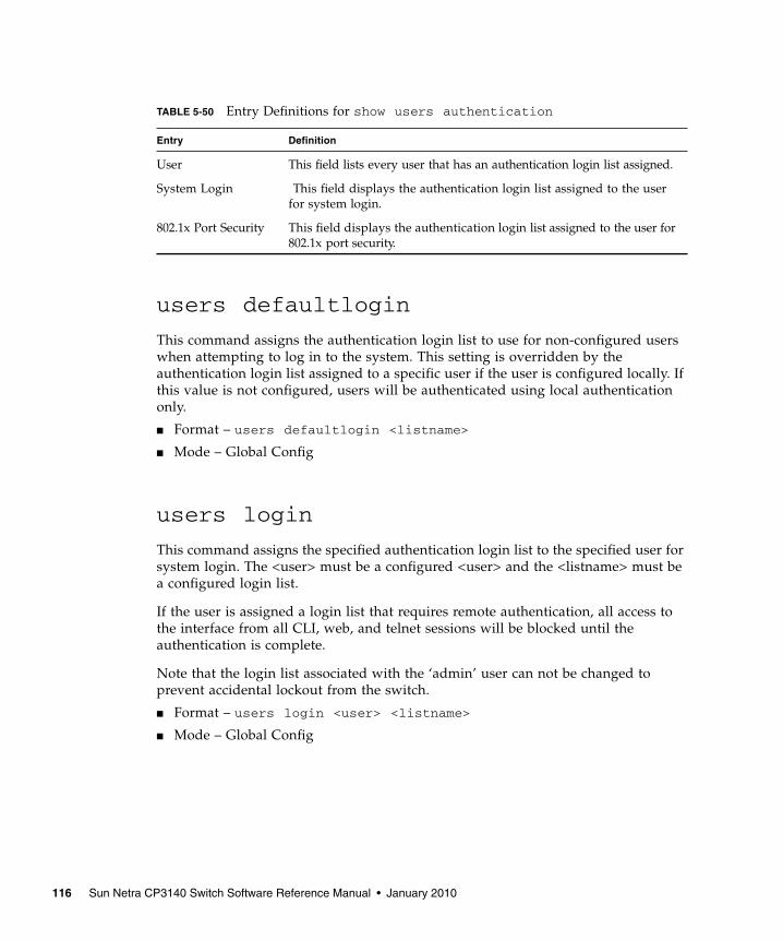
users defaultlogin
This command assigns the authentication login list to use for non-configured userswhen attempting to log in to the system. This setting is overridden by theauthentication login list assigned to a specific user if the user is configured locally. Ifthis value is not configured, users will be authenticated using local authenticationonly.
■ Format – users defaultlogin <listname>
■ Mode – Global Config
users login
This command assigns the specified authentication login list to the specified user forsystem login. The <user> must be a configured <user> and the <listname> must bea configured login list.
If the user is assigned a login list that requires remote authentication, all access tothe interface from all CLI, web, and telnet sessions will be blocked until theauthentication is complete.
Note that the login list associated with the ‘admin’ user can not be changed toprevent accidental lockout from the switch.
■ Format – users login <user> <listname>
■ Mode – Global Config
TABLE 5-50 Entry Definitions for show users authentication
Entry Definition
User This field lists every user that has an authentication login list assigned.
System Login This field displays the authentication login list assigned to the userfor system login.
802.1x Port Security This field displays the authentication login list assigned to the user for802.1x port security.
116 Sun Netra CP3140 Switch Software Reference Manual • January 2010
Remote Authentication Dial In UserService (RADIUS) CommandsThis section provides a detailed explanation of the RADIUS commands. Thecommands are divided into the following groups:
■ Configuration commands are used to configure features and options of theswitch. For every configuration command there is a show command that willdisplay the configuration setting.
■ Show commands are used to display switch settings, statistics and otherinformation.
radius accounting mode
This command is used to enable the RADIUS accounting function.
■ Default – disabled
■ Format – radius accounting mode
■ Mode – Global Config
no radius accounting mode
This command is used to set the RADIUS accounting function to the default value;that is, the RADIUS accounting function is disabled.
■ Format – no radius accounting mode
■ Mode – Global Config
radius server host
This command is used to configure the RADIUS authentication and accountingserver.
If the 'auth' token is used, the command configures the IP address to use to connectto a RADIUS authentication server. Up to 3 servers can be configured per RADIUSclient. If the maximum number of configured servers is reached, the command willfail until one of the servers is removed by executing the no form of the command. Ifthe optional <port> parameter is used, the command will configure the UDP portnumber to use to connect to the configured RADIUS server. In order to configure the
Chapter 5 Switching Commands 117
UDP port number, the IP address must match that of a previously configuredRADIUS authentication server. The port number must lie between 1-65535, with1812 being the default value.
If the 'acct' token is used, the command configures the IP address to use for theRADIUS accounting server. Only a single accounting server can be configured. If anaccounting server is currently configured, it must be removed from the configurationusing the no form of the command before this command succeeds. If the optional<port> parameter is used, the command will configure the UDP port to use toconnect to the RADIUS accounting server. The IP address specified must match thatof a previously configured accounting server. If a port is already configured for theaccounting server then the new port will replace the previously configured value.The port must be a value in the range 1 - 65535, with 1813 being the default value.
■ Format – radius server host {auth | acct} <ipaddr> [<port>]
■ Mode – Global Config
no radius server host
This command is used to remove the configured RADIUS authentication server orthe RADIUS accounting server. If the 'auth' token is used, the previously configuredRADIUS authentication server is removed from the configuration. Similarly, if the'acct' token is used, the previously configured RADIUS accounting server is removedfrom the configuration. The <ipaddr> parameter must match the IP address of thepreviously configured RADIUS authentication / accounting server.
■ Format – no radius server host {auth | acct} <ipaddress>
■ Mode – Global Config
radius server key
This command is used to configure the shared secret between the RADIUS client andthe RADIUS accounting / authentication server. Depending on whether the 'auth' or'acct' token is used, the shared secret will be configured for the RADIUSauthentication or RADIUS accounting server. The IP address provided must match apreviously configured server. When this command is executed, the secret will beprompted. The secret must be an alphanumeric value not exceeding 20 characters.
■ Format – radius server key {auth | acct} <ipaddr>
■ Mode – Global Config
118 Sun Netra CP3140 Switch Software Reference Manual • January 2010

radius server msgauth
This command enables the message authenticator attribute for a specified server.
■ Default – radius server msgauth <ipaddr>
■ Mode – Global Config
radius server primary
This command is used to configure the primary RADIUS authentication server forthis RADIUS client. The primary server is the one that is used by default forhandling RADIUS requests. The remaining configured servers are only used if theprimary server cannot be reached. A maximum of three servers can be configured oneach client. Only one of these servers can be configured as the primary. If a primaryserver is already configured prior to this command being executed, the serverspecified by the IP address specified used in this command will become the newprimary server. The IP address must match that of a previously configured RADIUSauthentication server.
■ Format – radius server primary <ipaddr>
■ Mode – Global Config
radius server retransmit
This command sets the maximum number of times a request packet is re-transmittedwhen no response is received from the RADIUS server. The retries value is aninteger in the range of 1 to 15.
■ Default – 10
■ Format – radius server retransmit <retries>
■ Mode – Global Config
no radius server retransmit
This command sets the maximum number of times a request packet is re-transmitted, when no response is received from the RADIUS server, to the defaultvalue, 10.
■ Format – no radius server retransmit
■ Mode – Global Config
Chapter 5 Switching Commands 119

radius server timeout
This command sets the timeout value (in seconds) after which a request must beretransmitted to the RADIUS server if no response is received. The timeout value isan integer in the range of 1 to 30.
■ Default – 6
■ Format – radius server timeout <seconds>
■ Mode – Global Config
no radius server timeout
This command sets the timeout value (in seconds) after which a request must beretransmitted to the RADIUS server if no response is received, to the default value,6.
■ Format – no radius server timeout
■ Mode – Global Config
show radius
This command is used to display the various RADIUS configuration items for theswitch as well as the configured RADIUS servers. If the optional token servers isnot included, the following RADIUS configuration items will be displayed.
■ Format – show radius [servers]
■ Mode – Privileged EXEC
TABLE 5-51 Entry Definitions for show radius With Token servers Not Included
Entry Definition
Primary Server IPAddress
Indicates the configured server currently in use for authentication
Number ofconfigured servers
The configured IP address of the authentication server
Max number ofretransmits
The configured value of the maximum number of times a requestpacket is retransmitted
Timeout Duration The configured timeout value, in seconds, for request re-transmissions
Accounting Mode Yes or No
120 Sun Netra CP3140 Switch Software Reference Manual • January 2010

If the optional token 'servers' is included, the following information regarding theconfigured RADIUS servers is displayed.
show radius statistics
This command is used to display the statistics for RADIUS or configured server . Toshow the configured RADIUS server statistic, the IP Address specified must matchthat of a previously configured RADIUS server. On execution, the following fieldsare displayed.
■ Format – show radius statistics [ipaddr]
■ Mode – Privileged EXEC
If the IP address is not specified only the Invalid Server Address field is displayed.Otherwise other listed fields are displayed.
TABLE 5-52 Entry Definitions for show radius With Token servers Included
Entry Definition
IP Address IP Address of the configured RADIUS server
Port The port in use by this server
Type Primary or secondary
Secret Configured Yes / No
MessageAuthenticator
Enables or disables. the message authenticator attribute for theselected server
TABLE 5-53 Entry Definitions for show radius statistics
Entry Definitions
Invalid ServerAddresses
The number of RADIUS Access-Response packets received fromunknown addresses.
Server IP Address IP Address of the server.
Round Trip Time The time interval, in hundredths of a second, between the mostrecent Access-Reply | Access-Challenge and the Access-Requestthat matched it from the RADIUS authentication server.
Access Requests The number of RADIUS Access-Request packets sent to this server.This number does not include retransmissions.
Access Retransmission The number of RADIUS Access-Request packets retransmitted to thisRADIUS authentication server.
Chapter 5 Switching Commands 121
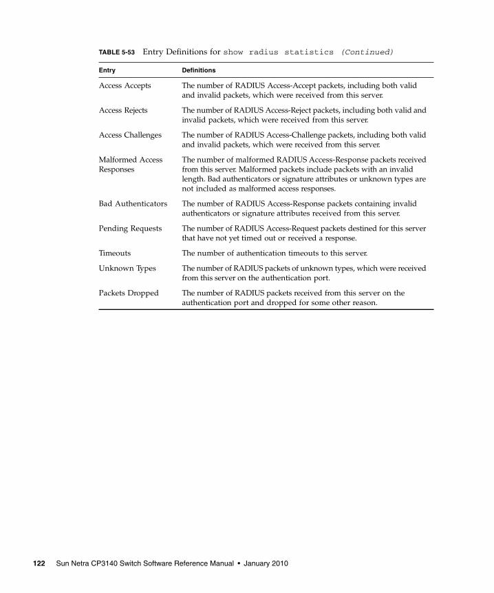
Access Accepts The number of RADIUS Access-Accept packets, including both validand invalid packets, which were received from this server.
Access Rejects The number of RADIUS Access-Reject packets, including both valid andinvalid packets, which were received from this server.
Access Challenges The number of RADIUS Access-Challenge packets, including both validand invalid packets, which were received from this server.
Malformed AccessResponses
The number of malformed RADIUS Access-Response packets receivedfrom this server. Malformed packets include packets with an invalidlength. Bad authenticators or signature attributes or unknown types arenot included as malformed access responses.
Bad Authenticators The number of RADIUS Access-Response packets containing invalidauthenticators or signature attributes received from this server.
Pending Requests The number of RADIUS Access-Request packets destined for this serverthat have not yet timed out or received a response.
Timeouts The number of authentication timeouts to this server.
Unknown Types The number of RADIUS packets of unknown types, which were receivedfrom this server on the authentication port.
Packets Dropped The number of RADIUS packets received from this server on theauthentication port and dropped for some other reason.
TABLE 5-53 Entry Definitions for show radius statistics (Continued)
Entry Definitions
122 Sun Netra CP3140 Switch Software Reference Manual • January 2010

Secure Shell (SSH) CommandsThis section provides a detailed explanation of the SSH commands. The commandsare divided into the following groups:
■ Configuration commands are used to configure features and options of theswitch. For every configuration command there is a show command that willdisplay the configuration setting.
■ Show commands are used to display switch settings, statistics and otherinformation.
ip ssh
This command is used to enable SSH.
■ Default – disabled
■ Format – ip ssh
■ Mode – Privileged EXEC
no ip ssh
This command is used to disable SSH.
■ Format – no ip ssh
■ Mode – Privileged EXEC
ip ssh protocol
This command is used to set or remove protocol levels (or versions) for SSH. EitherSSH1 (1), SSH2 (2), or both SSH 1 and SSH 2 (1 and 2) can be set.
■ Default – 1 and 2
■ Format – ip ssh protocol [1] [2]
■ Mode – Privileged EXEC
Chapter 5 Switching Commands 123

show ip ssh
This command displays the SSH settings.
■ Format – show ip ssh
■ Mode – Privileged EXEC
Hypertext Transfer Protocol (HTTP)CommandsThis section provides a detailed explanation of the HTTP commands. The commandsare divided into the following groups:
■ Configuration commands are used to configure features and options of theswitch. For every configuration command there is a show command that willdisplay the configuration setting.
■ Show commands are used to display switch settings, statistics and otherinformation.
ip http secure-port
This command is used to set the sslt port where port can be 1-65535 and the defaultis port 443.
■ Default – 443
■ Format – ip http secure-port <portid>
■ Mode – Privileged EXEC
TABLE 5-54 Entry Definitions for show ip ssh
Entry Definition
Administrative Mode This field indicates whether the administrative mode of SSH isenabled or disabled.
Protocol Level The protocol level may have the values of version 1, version 2 or bothversions 1 and version 2.
Connections This field specifies the current SSH connections.
124 Sun Netra CP3140 Switch Software Reference Manual • January 2010

no ip http secure-port
This command is used to reset the sslt port to the default value.
■ Format – no ip http secure-port
■ Mode – Privileged EXEC
ip http secure-protocol
This command is used to set protocol levels (versions). The protocol level can be setto TLS1, SSL3 or to both TLS1 and SSL3.
■ Default – SSL3 and TLS1
■ Format – ip http secure-protocol [SSL3] [TLS1]
■ Mode – Privileged EXEC
ip http secure-server
This command is used to enable the secure socket layer for secure HTTP.
■ Default – disabled
■ Format – ip http secure-server
■ Mode – Privileged EXEC
no ip http secure-server
This command is used to disable the secure socket layer for secure HTTP.
■ Format – ip http secure-server
■ Mode – Privileged EXEC
Chapter 5 Switching Commands 125
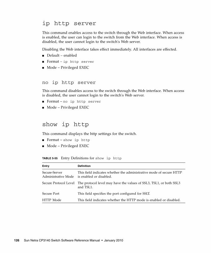
ip http server
This command enables access to the switch through the Web interface. When accessis enabled, the user can login to the switch from the Web interface. When access isdisabled, the user cannot login to the switch's Web server.
Disabling the Web interface takes effect immediately. All interfaces are effected.
■ Default – enabled
■ Format – ip http server
■ Mode – Privileged EXEC
no ip http server
This command disables access to the switch through the Web interface. When accessis disabled, the user cannot login to the switch's Web server.
■ Format – no ip http server
■ Mode – Privileged EXEC
show ip http
This command displays the http settings for the switch.
■ Format – show ip http
■ Mode – Privileged EXEC
TABLE 5-55 Entry Definitions for show ip http
Entry Definition
Secure-ServerAdministrative Mode
This field indicates whether the administrative mode of secure HTTPis enabled or disabled.
Secure Protocol Level The protocol level may have the values of SSL3, TSL1, or both SSL3and TSL1.
Secure Port This field specifies the port configured for SSLT.
HTTP Mode This field indicates whether the HTTP mode is enabled or disabled.
126 Sun Netra CP3140 Switch Software Reference Manual • January 2010
DHCP Server CommandsThese commands configure the DHCP Server parameters and address pools. Thecommands are divided by functionality into these different groups:
■ Configuration Commands are used to configure features and options of theswitch. For every configuration command there is a show command that willdisplay the configuration setting.
■ Show commands are used to display switch settings, statistics and otherinformation.
■ Clear commands clear some or all of the settings to factory defaults.
client-identifier
This command specifies the unique identifier for a DHCP client. Unique-identifier isa valid notation in hexadecimal format. In some systems, such as Microsoft DHCPclients, the client identifier is required instead of hardware addresses. The unique-identifier is a concatenation of the media type and the MAC address. For example,the Microsoft client identifier for Ethernet address c819.2488.f177 is 01c8.1924.88f1.77where 01 represents the Ethernet media type. Refer to the "Address ResolutionProtocol Parameters" section of RFC 1700, Assigned Numbers for a list of media typecodes.
■ Default – None
■ Format – client-identifier <uniqueidentifier>
■ Mode – DHCP Pool Config
no client-identifier
This command deletes the client identifier.
■ Format – no client-identifier
■ Mode – DHCP Pool Config
Chapter 5 Switching Commands 127

client-name
This command specifies the name for a DHCP client. Name is a string consisting ofstandard ASCII characters.
■ Default – None
■ Format – client-name <name>
■ Mode – DHCP Pool Config
no client-name
This command removes the client name.
■ Format – no client-name
■ Mode – DHCP Pool Config
default-router
This command specifies the default router list for a DHCP client. {address1,address2… address8} are valid IP addresses, each made up of four decimal bytesranging from 0 to 255. IP address 0.0.0.0 is invalid.
■ Default – None
■ Format – default-router <address1> [<address2>....<address8>]
■ Mode – DHCP Pool Config
no default-router
This command removes the default router list.
■ Format – no default-router
■ Mode – DHCP Pool Config
128 Sun Netra CP3140 Switch Software Reference Manual • January 2010
dns-server
This command specifies the IP servers available to a DHCP client. Addressparameters are valid IP addresses; each made up of four decimal bytes ranging from0 to 255. IP address 0.0.0.0 is invalid.
■ Default – none
■ Format – dns-server <address1> [<address2>....<address8>]
■ Mode – DHCP Pool Config
no dns-server
This command removes the DNS Server list.
■ Format – no dns-server
■ Mode – DHCP Pool Config
hardware-address
This command specifies the hardware address of a DHCP client.
Hardware-address is the MAC address of the hardware platform of the clientconsisting of 6 bytes in dotted hexadecimal format.
Type indicates the protocol of the hardware platform. It is 1 for 10 MB Ethernet and6 for IEEE 802.
■ Default – ethernet
■ Format – hardware-address <hardwareaddress> [type]
■ Mode – DHCP Pool Config
no hardware-address
This command removes the hardware address of the DHCP client.
■ Format – no hardware-address
■ Mode – DHCP Pool Config
Chapter 5 Switching Commands 129
host
This command specifies the IP address and network mask for a manual binding to aDHCP client. Address and Mask are valid IP addresses; each made up of fourdecimal bytes ranging from 0 to 255. IP address 0.0.0.0 is invalid.
The prefix-length is an integer from 0 to 32.
■ Default – none
■ Format – host <address> [mask | prefix-length]
■ Mode – DHCP Pool Config
no host
This command removes the IP address of the DHCP client.
■ Format – no host
■ Mode – DHCP Pool Config
ip dhcp excluded-address
This command specifies the IP addresses that a DHCP server should not assign toDHCP clients. Low-address and high-address are valid IP addresses; each made upof four decimal bytes ranging from 0 to 255. IP address 0.0.0.0 is invalid.
■ Default – none
■ Format – ip dhcp excluded-address <lowaddress> [highaddress]
■ Mode – Global Config
no ip dhcp excluded-address
This command removes the excluded IP addresses for a DHCP client. Low-addressand high-address are valid IP addresses; each made up of four decimal bytesranging from 0 to 255. IP address 0.0.0.0 is invalid.
■ Format – no ip dhcp excluded-address <lowaddress> [highaddress]
■ Mode – Global Config
130 Sun Netra CP3140 Switch Software Reference Manual • January 2010

ip dhcp ping packets
This command is used to specify the number in a range from 2-10, of packets aDHCP server sends to a pool address as part of a ping operation. Setting the numberof ping packets to 0 is the same as ‘no ip dhcp ping packets’ and will prevent theserver from pinging pool addresses.
■ Default – 2
■ Format – ip dhcp ping packets <0,2-10>
■ Mode – Global Config
no ip dhcp ping packets
This command prevents the server from pinging pool addresses and will set thenumber of packets to 0.
■ Default – 0
■ Format – no ip dhcp ping packets
■ Mode – Global Config
ip dhcp pool
This command configures a DHCP address pool name on a DHCP server and entersDHCP pool configuration mode.
■ Default – none
■ Format – ip dhcp pool <name>
■ Mode – Global Config Mode
no ip dhcp pool
This command removes the DHCP address pool. The name should be previouslyconfigured pool name.
■ Format – no ip dhcp pool <name>
■ Mode – Global Config Mode
Chapter 5 Switching Commands 131

lease
This command configures the duration of the lease for an IP address that is assignedfrom a DHCP server to a DHCP client. The overall lease time should be between 1-86400 minutes. If infinite is specified, lease is set for 60 days. Days is an integer from0 to 59. Hours is an integer from 0 to 1439. Minutes is an integer from 0 to 86399.
■ Default – 1 (day)
■ Format – lease {[<days> [hours] [minutes]] | [infinite]}
■ Mode – DHCP Pool Config
no lease
This command restores the default value of the lease time for DHCP Server.
■ Format – no lease
■ Mode – DHCP Pool Config
network
This command is used to configure the subnet number and mask for a DHCPaddress pool on the server. Network-number is a valid IP address, made up of fourdecimal bytes ranging from 0 to 255. IP address 0.0.0.0 is invalid. Mask is the IPsubnet mask for the specified address pool. The prefix-length is an integer from 0 to32.
■ Default – none
■ Format – network <networknumber> [mask | prefixlength]
■ Mode – DHCP Pool Config
no network
This command removes the subnet number and mask.
■ Format – no network
■ Mode – DHCP Pool Config
132 Sun Netra CP3140 Switch Software Reference Manual • January 2010
service dhcp
This command enables the DHCP server and relay agent features on the router.
■ Default – disabled
■ Format – service dhcp
■ Mode – Global Config
no service dhcp
This command disables the DHCP server and relay agent features.
■ Format – no service dhcp
■ Mode – Global Config
bootfile
The command specifies the name of the default boot image for a DHCP client. The<filename> specifies the boot image file.
■ Default – none
■ Format – bootfile <filename>
■ Mode – DHCP Pool Config
no bootfile
This command deletes the boot image name.
■ Format – no bootfile
■ Mode – DHCP Pool Config
domain-name
This command specifies the domain name for a DHCP client. The <domain>specifies the domain name string of the client.
■ Default – none
■ Format – domain-name <domain>
■ Mode – DHCP Pool Config
Chapter 5 Switching Commands 133

no domain-name
This command removes the domain name.
■ Format – no domain-name
■ Mode – DHCP Pool Config
ip dhcp bootp automatic
This command enables the allocation of the addresses to the bootp client. Theaddresses are from the automatic address pool.
■ Default – disable
■ Format – ip dhcp bootp automatic
■ Mode – Global Config
no ip dhcp bootp automatic
This command disables the allocation of the addresses to the bootp client. Theaddress are from the automatic address pool.
■ Format – no ip dhcp bootp automatic
■ Mode – Global Config
ip dhcp conflict logging
This command enables conflict logging on DHCP server.
■ Default – enabled
■ Format – ip dhcp conflict logging
■ Mode – Global Config
no ip dhcp conflict logging
This command disables conflict logging on DHCP server.
■ Format – no ip dhcp conflict logging
■ Mode – Global Config
134 Sun Netra CP3140 Switch Software Reference Manual • January 2010
netbios-name-server
This command configures NetBIOS Windows Internet Naming Service (WINS) nameservers that are available to DHCP clients.
One IP address is required, although one can specify up to eight addresses in onecommand line. Servers are listed in order of preference (address1 is the mostpreferred server, address2 is the next most preferred server, and so on).
■ Default – none
■ Format – netbios-name-server <address>[<address2>...<address8>]
■ Mode – DHCP Pool Config
no netbios-name-server
This command removes the NetBIOS name server list.
■ Format – no netbios-name-server
■ Mode – DHCP Pool Config
netbios-node-type
The command configures the NetBIOS node type for Microsoft Dynamic HostConfiguration Protocol (DHCP) clients.type Specifies the NetBIOS node type. Validtypes are:
■ b-node – Broadcast
■ p-node – Peer-to-peer
■ m-node – Mixed
■ h-node – Hybrid (recommended)
Following are the formats and modes for the netbios-node-type command.
■ Default – none
■ Format – netbios-node-type <type>
■ Mode – DHCP Pool Config
Chapter 5 Switching Commands 135
no netbios-node-type
This command removes the NetBIOS node Type.
■ Format – no netbios-node-type
■ Mode – DHCP Pool Config
next-server
This command configures the next server in the boot process of a DHCP client.
Address is the IP address of the next server in the boot process, which is typically aTrivial File Transfer Protocol (TFTP) server.
■ Default – If the next-server command is not used to configure a boot server list, theDHCP Server uses inbound interface helper addresses as boot servers.
■ Format – next-server <address>
■ Mode – DHCP Pool Config
no next-server
This command removes the boot server list.
■ Format – no next-server
■ Mode – DHCP Pool Config
option
The command configures DHCP Server options. Code specifies the DHCP optioncode. Ascii string specifies an NVT ASCII character string. ASCII character stringsthat contain white space must be delimited by quotation marks. Hex string specifieshexadecimal data. in hexadecimal character strings is two hexadecimal digits—eachbyte can be separated by a period, colon, or white space.
Example :a3:4f:22:0c / a3 4f 22 0c / a34f.220c.9fed The <address> specifies an IPaddress.
■ Default – none
■ Format – option <code> {ascii string | hex <string1>[<string2>...<string8> ] | ip <address1>[<address2>...<address8> ]}
■ Mode – DHCP Pool Config
136 Sun Netra CP3140 Switch Software Reference Manual • January 2010

no option
This command removes the options.
■ Format – no option <code>
■ Mode – DHCP Pool Config
show ip dhcp binding
This command displays address bindings for the specific IP address on the DHCPserver. If no IP address is specified, the bindings corresponding to all the addressesare displayed.
■ Format – show ip dhcp binding [address]
■ Mode – Privileged EXEC and User EXEC
show ip dhcp global configuration
This command displays address bindings for the specific IP address on the DHCPserver. If no IP address is specified, the bindings corresponding to all the addressesare displayed.
■ Format – show ip dhcp global configuration
■ Mode – Privileged EXEC and User EXEC
TABLE 5-56 Entry Definitions for show ip dhcp binding
Entry Definition
IP address The IP address of the client.
Hardware Address The MAC Address or the client identifier.
Lease expiration The lease expiration time of the IP Address assigned to the client.
Type The manner in which IP Address was assigned to the client.
Chapter 5 Switching Commands 137
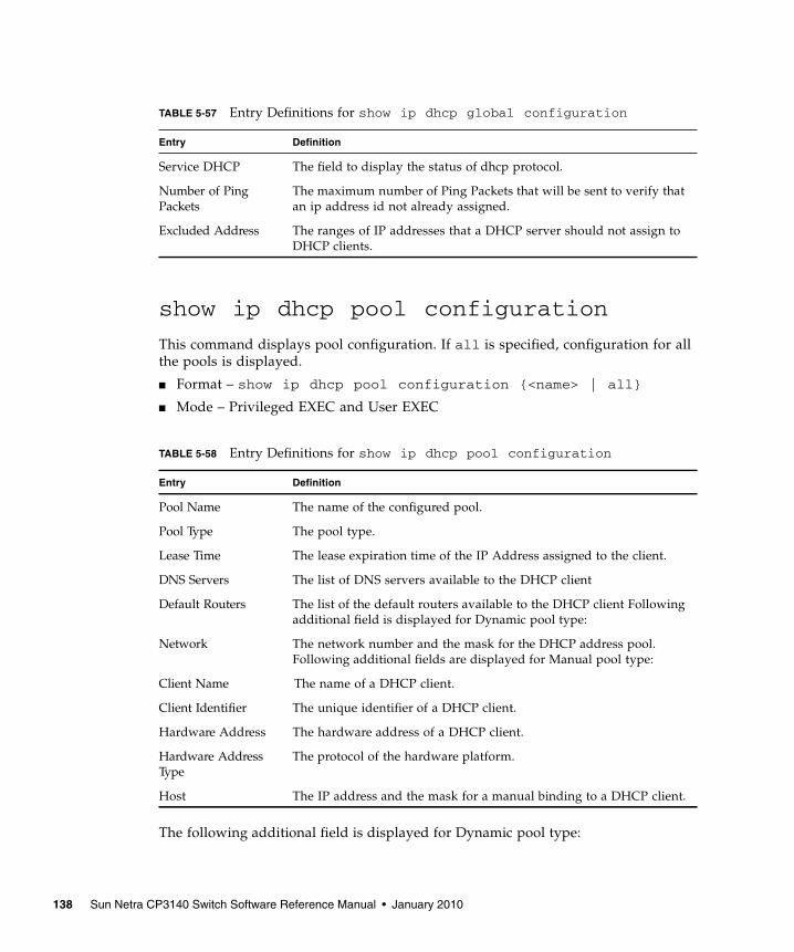
show ip dhcp pool configuration
This command displays pool configuration. If all is specified, configuration for allthe pools is displayed.
■ Format – show ip dhcp pool configuration {<name> | all}
■ Mode – Privileged EXEC and User EXEC
The following additional field is displayed for Dynamic pool type:
TABLE 5-57 Entry Definitions for show ip dhcp global configuration
Entry Definition
Service DHCP The field to display the status of dhcp protocol.
Number of PingPackets
The maximum number of Ping Packets that will be sent to verify thatan ip address id not already assigned.
Excluded Address The ranges of IP addresses that a DHCP server should not assign toDHCP clients.
TABLE 5-58 Entry Definitions for show ip dhcp pool configuration
Entry Definition
Pool Name The name of the configured pool.
Pool Type The pool type.
Lease Time The lease expiration time of the IP Address assigned to the client.
DNS Servers The list of DNS servers available to the DHCP client
Default Routers The list of the default routers available to the DHCP client Followingadditional field is displayed for Dynamic pool type:
Network The network number and the mask for the DHCP address pool.Following additional fields are displayed for Manual pool type:
Client Name The name of a DHCP client.
Client Identifier The unique identifier of a DHCP client.
Hardware Address The hardware address of a DHCP client.
Hardware AddressType
The protocol of the hardware platform.
Host The IP address and the mask for a manual binding to a DHCP client.
138 Sun Netra CP3140 Switch Software Reference Manual • January 2010

Following additional fields are displayed for Manual pool type:
show ip dhcp server statistics
This command displays DHCP server statistics.
■ Format – show ip dhcp server statistics
■ Mode – Privileged EXEC and User EXEC
TABLE 5-59 Field for Dynamic pool type for show ip dhcp pool configuration
Entry Definition
Network The network number and the mask for the DHCP address pool.
TABLE 5-60 Field for Manual pool type for show ip dhcp pool configuration
Entry Definition
Client Name The name of a DHCP client.
Client Identifier The unique identifier of a DHCP client.
Hardware Address The hardware address of a DHCP client.
Hardware AddressType
The protocol of the hardware platform.
Host The IP address and the mask for a manual binding to a DHCP client.
TABLE 5-61 Entry Definitions for show ip dhcp server statistics
Entry Defintion
Address Pool The number of configured address pools in the DHCP server.
Automatic bindings The number of IP addresses that have been automatically mapped tothe MAC addresses of hosts that are found in the DHCP database.
Manual bindings The number of IP addresses that have been manually mapped to theMAC addresses of hosts that are found in the DHCP database.
Expired bindings The number of expired leases.
Malformed messages The number of truncated or corrupted messages that were receivedby the DHCP server.
Chapter 5 Switching Commands 139
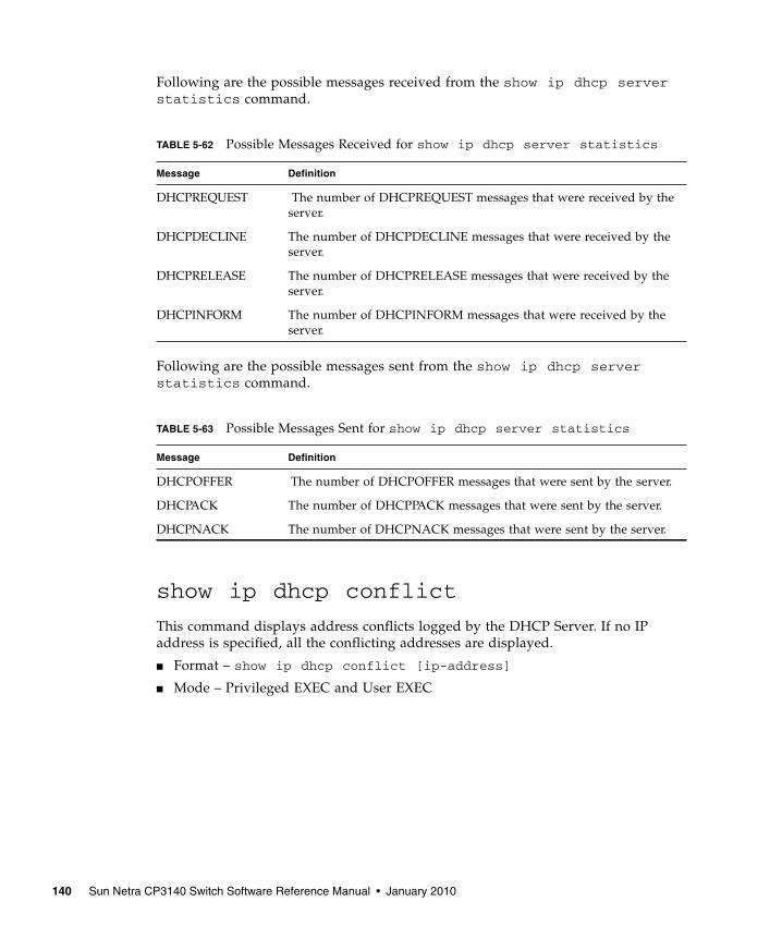
Following are the possible messages received from the show ip dhcp serverstatistics command.
Following are the possible messages sent from the show ip dhcp serverstatistics command.
show ip dhcp conflict
This command displays address conflicts logged by the DHCP Server. If no IPaddress is specified, all the conflicting addresses are displayed.
■ Format – show ip dhcp conflict [ip-address]
■ Mode – Privileged EXEC and User EXEC
TABLE 5-62 Possible Messages Received for show ip dhcp server statistics
Message Definition
DHCPREQUEST The number of DHCPREQUEST messages that were received by theserver.
DHCPDECLINE The number of DHCPDECLINE messages that were received by theserver.
DHCPRELEASE The number of DHCPRELEASE messages that were received by theserver.
DHCPINFORM The number of DHCPINFORM messages that were received by theserver.
TABLE 5-63 Possible Messages Sent for show ip dhcp server statistics
Message Definition
DHCPOFFER The number of DHCPOFFER messages that were sent by the server.
DHCPACK The number of DHCPPACK messages that were sent by the server.
DHCPNACK The number of DHCPNACK messages that were sent by the server.
140 Sun Netra CP3140 Switch Software Reference Manual • January 2010

clear ip dhcp binding
This command deletes an automatic address binding from the DHCP serverdatabase. If “*” is specified, the bindings corresponding to all the addresses aredeleted. <address> is a valid IP address made up of four decimal bytes ranging from0 to 255. IP address 0.0.0.0 is invalid.
■ Default – none
■ Format – clear ip dhcp binding {address | *}
■ Mode – Privileged EXEC
clear ip dhcp server statistics
This command clears DHCP server statistics counters.
■ Format – clear ip dhcp server statistics
■ Mode – Privileged EXEC
clear ip dhcp conflict
The command is used to clear an address conflict from the DHCP Server database.The server detects conflicts using a ping. DHCP server clears all conflicts If theasterisk (*) character is used as the address parameter.
■ Default – none
■ Format – clear ip dhcp conflict {<address> | *}
■ Mode – Privileged EXEC
TABLE 5-64 Entry Definitions for show ip dhcp conflict
Entry Definition
IP address The IP address of the host as recorded on the DHCP server.
Detection Method The manner in which the IP address of the hosts were found on theDHCP Server
Detection time The time when the conflict was found.
Chapter 5 Switching Commands 141
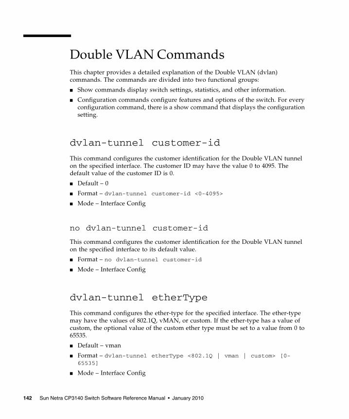
Double VLAN CommandsThis chapter provides a detailed explanation of the Double VLAN (dvlan)commands. The commands are divided into two functional groups:
■ Show commands display switch settings, statistics, and other information.
■ Configuration commands configure features and options of the switch. For everyconfiguration command, there is a show command that displays the configurationsetting.
dvlan-tunnel customer-id
This command configures the customer identification for the Double VLAN tunnelon the specified interface. The customer ID may have the value 0 to 4095. Thedefault value of the customer ID is 0.
■ Default – 0
■ Format – dvlan-tunnel customer-id <0-4095>
■ Mode – Interface Config
no dvlan-tunnel customer-id
This command configures the customer identification for the Double VLAN tunnelon the specified interface to its default value.
■ Format – no dvlan-tunnel customer-id
■ Mode – Interface Config
dvlan-tunnel etherType
This command configures the ether-type for the specified interface. The ether-typemay have the values of 802.1Q, vMAN, or custom. If the ether-type has a value ofcustom, the optional value of the custom ether type must be set to a value from 0 to65535.
■ Default – vman
■ Format – dvlan-tunnel etherType <802.1Q | vman | custom> [0-65535]
■ Mode – Interface Config
142 Sun Netra CP3140 Switch Software Reference Manual • January 2010

no dvlan-tunnel etherType
This command configures the ether-type for the specified interface to its defaultvalue.
■ Format – no dvlan-tunnel etherType
■ Mode – Interface Config
mode dot1q-tunnel
This command is used to enable Double VLAN Tunneling on the specified interface.By default, Double VLAN Tunneling is disabled.
■ Default – disabled
■ Format – mode dot1q-tunnel
■ Mode – Interface Config
no mode dot1q-tunnel
This command is used to disable Double VLAN Tunneling on the specified interface.By default, Double VLAN Tunneling is disabled.
■ Format – no mode dot1q-tunnel
■ Mode – Interface Config
mode dvlan-tunnel
This command is used to enable Double VLAN Tunneling on the specified interface.By default, Double VLAN Tunneling is disabled.
■ Default – disabled
■ Format – mode dvlan-tunnel
■ Mode – Interface Config
no mode dvlan-tunnel
This command is used to disable Double VLAN Tunneling on the specified interface.By default, Double VLAN Tunneling is disabled.
■ Format – no mode dvlan-tunnel
■ Mode – Interface Config
Chapter 5 Switching Commands 143
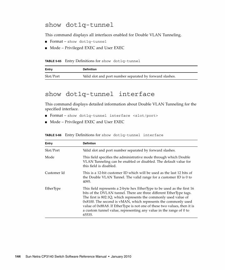
show dot1q-tunnel
This command displays all interfaces enabled for Double VLAN Tunneling.
■ Format – show dot1q-tunnel
■ Mode – Privileged EXEC and User EXEC
show dot1q-tunnel interface
This command displays detailed information about Double VLAN Tunneling for thespecified interface.
■ Format – show dot1q-tunnel interface <slot/port>
■ Mode – Privileged EXEC and User EXEC
TABLE 5-65 Entry Definitions for show dot1q-tunnel
Entry Definition
Slot/Port Valid slot and port number separated by forward slashes.
TABLE 5-66 Entry Definitions for show dot1q-tunnel interface
Entry Defintion
Slot/Port Valid slot and port number separated by forward slashes.
Mode This field specifies the administrative mode through which DoubleVLAN Tunneling can be enabled or disabled. The default value forthis field is disabled.
Customer Id This is a 12-bit customer ID which will be used as the last 12 bits ofthe Double VLAN Tunnel. The valid range for a customer ID is 0 to4095.
EtherType This field represents a 2-byte hex EtherType to be used as the first 16bits of the DVLAN tunnel. There are three different EtherType tags.The first is 802.1Q, which represents the commonly used value of0x8100. The second is vMAN, which represents the commonly usedvalue of 0x88A8. If EtherType is not one of these two values, then it isa custom tunnel value, representing any value in the range of 0 to65535.
144 Sun Netra CP3140 Switch Software Reference Manual • January 2010
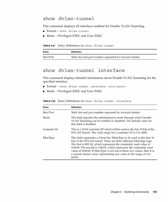
show dvlan-tunnel
This command displays all interfaces enabled for Double VLAN Tunneling.
■ Format – show dvlan-tunnel
■ Mode – Privileged EXEC and User EXEC
show dvlan-tunnel interface
This command displays detailed information about Double VLAN Tunneling for thespecified interface.
■ Format – show dvlan-tunnel interface <slot/port>
■ Mode – Privileged EXEC and User EXEC
TABLE 5-67 Entry Definitions for show dvlan-tunnel
Entry Definition
Slot/Port Valid slot and port number separated by forward slashes.
TABLE 5-68 Entry Definitions for show dvlan-tunnel interface
Entry Definition
Slot/Port Valid slot and port number separated by forward slashes.
Mode This field specifies the administrative mode through which DoubleVLAN Tunneling can be enabled or disabled. The default value forthis field is disabled.
Customer Id This is a 12-bit customer ID which will be used as the last 12 bits of theDVLAN Tunnel. The valid range for a customer ID is 0 to 4095.
EtherType This field represents a 2-byte hex EtherType to be used as the first 16bits of the DVLAN tunnel. There are three different EtherType tags.The first is 802.1Q, which represents the commonly used value of0x8100. The second is vMAN, which represents the commonly usedvalue of 0x88A8. If EtherType is not one of these two values, then it isa custom tunnel value, representing any value in the range of 0 to65535.
Chapter 5 Switching Commands 145
Provisioning (IEEE 802.1p) CommandsThis chapter provides a detailed explanation of the Provisioning commands. Thecommands are divided into two functional groups:
■ Show commands display switch settings, statistics, and other information.
■ Configuration commands configure features and options of the switch. For everyconfiguration command, there is a show command that displays the configurationsetting.
classofservice dot1pmapping
This command maps an 802.1p priority to an internal traffic class for a device whenin ‘Global Config’ mode. The number of available traffic classes may vary with theplatform. Userpriority and trafficclass can both be the range from 0-7. The commandis only available on platforms that support priority to traffic class mapping on a‘per-port’ basis, and the number of available traffic classes may vary with theplatform.
■ Format – classofservice dot1pmapping <userpriority><trafficclass>
■ Mode – Global Config or Interface Config
show classofservice dot1pmapping
This command displays the current 802.1p priority mapping to internal trafficclasses for a specific interface. The slot/port parameter is required on platforms thatsupport priority to traffic class mapping on a ‘per-port’ basis.
Platforms that support priority to traffic class mapping on a per-port basis:
■ Format – show classofservice dot1pmapping <slot/port>
Platforms that do not support priority to traffic class mapping on a per-port basis:
■ Format – show classofservice dot1pmapping
■ Mode – Privileged EXEC and User EXEC
146 Sun Netra CP3140 Switch Software Reference Manual • January 2010

vlan port priority all
This command configures the port priority assigned for untagged packets for allports presently plugged into the device. The range for the priority is 0-7. Anysubsequent per port configuration will override this configuration setting.
■ Format – vlan port priority all <priority>
■ Mode – Global Config
vlan priority
This command configures the default 802.1p port priority assigned for untaggedpackets for a specific interface. The range for the priority is 0-7
■ Default – 0
■ Format – vlan priority <priority>
■ Mode – Interface Config
GARP CommandsThis chapter provides a detailed explanation of the GARP commands. Thecommands are divided into two functional groups:
■ Show commands display switch settings, statistics, and other information.
■ Configuration commands configure features and options of the switch. For everyconfiguration command, there is a show command that displays the configurationsetting.
set garp timer join
This command sets the GVRP join time per port and per GARP. Join time is theinterval between the transmission of GARP Protocol Data Units (PDUs) registering(or re-registering) membership for a VLAN or multicast group.
This command has an effect only when GVRP is enabled. The time is from 10 to 100(centiseconds). the value 20 centiseconds is 0.2 seconds.
■ Default – 20
■ Format – set garp timer join <10-100>
■ Mode – Interface Config
Chapter 5 Switching Commands 147

no set garp timer join
This command sets the GVRP join time per port and per GARP to 20 centiseconds(0.2 seconds). This command has an effect only when GVRP is enabled.
■ Format – no set garp timer join
■ Mode – Interface Config
set garp timer join all
This command sets the GVRP join time for all ports and per GARP. Join time is theinterval between the transmission of GARP Protocol Data Units (PDUs) registering(or re-registering) membership for a VLAN or multicast group.
This command has an effect only when GVRP is enabled. The time is from 10 to 100(centiseconds). The value 20 centiseconds is 0.2 seconds.
■ Default – 20
■ Format – set garp timer join all <10-100>
■ Mode – Global Config
no set garp timer join all
This command sets the GVRP join time for all ports and per GARP to 20centiseconds (0.2 seconds). This command has an effect only when GVRP is enabled.
■ Format – no set garp timer join all
■ Mode – Global Config
148 Sun Netra CP3140 Switch Software Reference Manual • January 2010

set garp timer leave
This command sets the GVRP leave time per port. Leave time is the time to waitafter receiving an unregister request for a VLAN or a multicast group before deletingthe VLAN entry. This can be considered a buffer time for another station to assertregistration for the same attribute in order to maintain uninterrupted service.time is20 to 600 (centiseconds). The value 60 centiseconds is 0.6 seconds.
Note – This command has an effect only when GVRP is enabled.
■ Default – 60
■ Format – set garp timer leave <20-600>
■ Mode – Interface Config
no set garp timer leave
This command sets the GVRP leave time per port to 60 centiseconds (0.6 seconds).
Note – This command has an effect only when GVRP is enabled.
■ Format – no set garp timer leave
■ Mode – Interface Config
set garp timer leave all
This command sets the GVRP leave time for all ports. Leave time is the time to waitafter receiving an unregister request for a VLAN or a multicast group before deletingthe VLAN entry. This can be considered a buffer time for another station to assertregistration for the same attribute in order to maintain uninterrupted service.time is20 to 600 (centiseconds). The value 60 centiseconds is 0.6 seconds.
Note – This command has an effect only when GVRP is enabled.
■ Default – 60
■ Format – set garp timer leave all <20-600>
■ Mode – Global Config
Chapter 5 Switching Commands 149
no set garp timer leave all
This command sets the GVRP leave time for all ports to the default 60 centiseconds(0.6 seconds).
Note – This command has an effect only when GVRP is enabled.
■ Format – no set garp timer leave all
■ Mode – Global Config
set garp timer leaveall
This command sets how frequently Leave All PDUs are generated per port. A LeaveAll PDU indicates that all registrations will be unregistered. Participants would needto rejoin in order to maintain registration. The value applies per port and per GARPparticipation. The time may range from 200 to 6000 (centiseconds). The value 1000centiseconds is 10 seconds.
Note – This command has an effect only when GVRP is enabled.
■ Default – 1000
■ Format – set garp timer leaveall <200-6000>
■ Mode – Interface Config
no set garp timer leaveall
This command sets how frequently Leave All PDUs are generated per port to 1000centiseconds (10 seconds). .
Note – This command has an effect only when GVRP is enabled.
■ Format – no set garp timer leaveall
■ Mode – Interface Config
150 Sun Netra CP3140 Switch Software Reference Manual • January 2010

set garp timer leaveall all
This command sets how frequently Leave All PDUs are generated for all ports. ALeave All PDU indicates that all registrations will be unregistered. Participantswould need to rejoin in order to maintain registration. The value applies per portand per GARP participation. The time may range from 200 to 6000 (centiseconds).The value 1000 centiseconds is 10 seconds.
Note – This command has an effect only when GVRP is enabled.
■ Default – 1000
■ Format – set garp timer leaveall all <200-6000>
■ Mode – Global Config
no set garp timer leaveall all
This command sets how frequently Leave All PDUs are generated for all ports to1000 centiseconds (10 seconds).
Note – This command has an effect only when GVRP is enabled.
■ Format – no set garp timer leaveall all
■ Mode – Global Config
show garp
This command displays Generic Attributes Registration Protocol (GARP)information.
■ Format – show garp
■ Mode – Privileged EXEC and User EXEC
TABLE 5-69 Entry Definitions for show garp
Entry Definition
GMRP Admin Mode This displays the administrative mode of GARP Multicast RegistrationProtocol (GMRP) for the system.
GVRP Admin Mode This displays the administrative mode of GARP VLAN RegistrationProtocol (GVRP) for the system
Chapter 5 Switching Commands 151

GARP VLAN Registration Protocol(GVRP) CommandsThis chapter provides a detailed explanation of the GVRP commands. Thecommands are divided into two functional groups:
■ Show commands display switch settings, statistics, and other information.
■ Configuration commands configure features and options of the switch. For everyconfiguration command, there is a show command that displays the configurationsetting.
set gvrp adminmode
This command enables GVRP.
■ Default – disabled
■ Format – set gvrp adminmode
■ Mode – Privileged EXEC
no set gvrp adminmode
This command disables GVRP.
■ Format – no set gvrp adminmode
■ Mode – Privileged EXEC
set gvrp interfacemode
This command enables GVRP (GARP VLAN Registration Protocol) for a specificport.
■ Default – disabled
■ Format – set gvrp interfacemode
■ Mode – Interface Config
152 Sun Netra CP3140 Switch Software Reference Manual • January 2010

no set gvrp interfacemode
This command disables GVRP (GARP VLAN Registration Protocol) for a specificport. If GVRP is disabled, Join Time, Leave Time and Leave All Time have no effect.
■ Format – no set gvrp interfacemode
■ Mode – Interface Config
set gvrp interfacemode all
This command enables GVRP (GARP VLAN Registration Protocol) for all ports.
■ Default – disabled
■ Format – set gvrp interfacemode all
■ Mode – Global Config
no set gvrp interfacemode all
This command disables GVRP (GARP VLAN Registration Protocol) for all ports. IfGVRP is disabled, Join Time, Leave Time and Leave All Time have no effect.
■ Format – no set gvrp interfacemode all
■ Mode – Global Config
show gvrp configuration
This command displays Generic Attributes Registration Protocol (GARP)information for one or all interfaces.
■ Format – show gvrp configuration {<slot/port> | all}
■ Mode – Privileged EXEC and User EXEC
Chapter 5 Switching Commands 153

TABLE 5-70 Entry Definitions for show gvrp configuration
Entry Definition
Interface Valid slot and port number separated by forward slashes.
Join Timer Specifies the interval between the transmission of GARP PDUsregistering (or re-registering) membership for an attribute. Currentattributes are a VLAN or multicast group. There is an instance of thistimer on a per-Port, per-GARP participant basis. Permissible valuesare 10 to 100 centiseconds (0.1 to 1.0 seconds). The factory default is 20centiseconds (0.2 seconds). The finest granularity of specification is 1centisecond (0.01 seconds).
Leave Timer Specifies the period of time to wait after receiving an unregister requestfor an attribute before deleting the attribute. Current attributes are aVLAN or multicast group. This may be considered a buffer time foranother station to assert registration for the same attribute in order tomaintain uninterrupted service. There is an instance of this timer on aper-Port, per-GARP participant basis. Permissible values are 20 to 600centiseconds (0.2 to 6.0 seconds). The factory default is 60 centiseconds(0.6 seconds). The finest granularity of specification is 1 centisecond (0.01seconds).
LeaveAll Timer This Leave All Time controls how frequently LeaveAll PDUs aregenerated. A LeaveAll PDU indicates that all registrations will shortlybe deregistered. Participants will need to rejoin in order to maintainregistration. There is an instance of this timer on a per-Port, per-GARPparticipant basis. The Leave All Period Timer is set to a random value inthe range of LeaveAll-Time to 1.5*LeaveAllTime. Permissible valuesare 200 to 6000 centiseconds (2 to 60 seconds). The factory default is1000 centiseconds (10 seconds). The finest granularity of specification is1 centisecond (0.01 seconds).
Port GMRP Mode Indicates the GMRP administrative mode for the port. It may beenabled or disabled. If this parameter is disabled, Join Time, LeaveTime and Leave All Time have no effect. The factory default is disabled.
154 Sun Netra CP3140 Switch Software Reference Manual • January 2010
GARP Multicast Registration Protocol(GMRP) CommandsThis chapter provides a detailed explanation of the GMRP commands. Thecommands are divided into two functional groups:
■ Show commands display switch settings, statistics, and other information.
■ Configuration commands configure features and options of the switch. For everyconfiguration command, there is a show command that displays the configurationsetting.
set gmrp adminmode
This command enables GARP Multicast Registration Protocol (GMRP) on thesystem. The default value is disable.
■ Format – set gmrp adminmode
■ Mode – Privileged EXEC
no set gmrp adminmode
This command disables GARP Multicast Registration Protocol (GMRP) on thesystem.
■ Format – no set gmrp adminmode
■ Mode – Privileged EXEC
set gmrp interfacemode
This command enables GARP Multicast Registration Protocol on a selected interface.If an interface which has GARP enabled is enabled for routing or is enlisted as amember of a port-channel (LAG), GARP functionality will be disabled on thatinterface. GARP functionality will subsequently be re-enabled if routing is disabledand port-channel (LAG) membership is removed from an interface that has GARPenabled.
■ Default – disabled
■ Format – set gmrp interfacemode
■ Mode – Interface Config
Chapter 5 Switching Commands 155

no set gmrp interfacemode
This command disables GARP Multicast Registration Protocol on a selectedinterface. If an interface which has GARP enabled is enabled for routing or isenlisted as a member of a port-channel (LAG), GARP functionality will be disabledon that interface. GARP functionality will subsequently be re-enabled if routing isdisabled and port-channel (LAG) membership is removed from an interface that hasGARP enabled.
■ Format – no set gmrp interfacemode
■ Mode – Interface Config
set gmrp interfacemode all
This command enables GARP Multicast Registration Protocol on all interfaces. If aninterface which has GARP enabled is enabled for routing or is enlisted as a memberof a port-channel (LAG), GARP functionality will be disabled on that interface.GARP functionality will subsequently be re-enabled if routing is disabled and port-channel (LAG) membership is removed from an interface that has GARP enabled.
■ Default – disabled
■ Format – set gmrp interfacemode all
■ Mode – Global Config
no set gmrp interfacemode all
This command disables GARP Multicast Registration Protocol on a selectedinterface.
■ Format – no set gmrp interfacemode all
■ Mode – Global Config
show gmrp configuration
This command displays Generic Attributes Registration Protocol (GARP)information for one or all interfaces.
■ Format – show gmrp configuration {<slot/port> | all}
■ Mode – Privileged EXEC and User EXEC
156 Sun Netra CP3140 Switch Software Reference Manual • January 2010
show mac-address-table gmrp
This command displays the GARP Multicast Registration Protocol (GMRP) entries inthe Multicast Forwarding Database (MFDB) table.
■ Format – show mac-address-table gmrp
■ Mode – Privileged EXEC
TABLE 5-71 Entry Definitions for show gmrp configuration
Entry Definition
Interface This displays the slot/port of the interface that this row in the tabledescribes.
Join Timer Specifies the interval between the transmission of GARP PDUsregistering (or re-registering) membership for an attribute. Currentattributes are a VLAN or multicast group. There is an instance of thistimer on a per-Port, per-GARP participant basis. Permissible valuesare 10 to 100 centiseconds (0.1 to 1.0 seconds). The factory default is 20centiseconds (0.2 seconds). The finest granularity of specification is 1centisecond (0.01 seconds).
Leave Timer Specifies the period of time to wait after receiving an unregister requestfor an attribute before deleting the attribute. Current attributes are aVLAN or multicast group. This may be considered a buffer time foranother station to assert registration for the same attribute in order tomaintain uninterrupted service. There is an instance of this timer on aper-Port, per-GARP participant basis. Permissible values are 20 to 600centiseconds (0.2 to 6.0 seconds). The factory default is 60 centiseconds(0.6 seconds). The finest granularity of specification is 1 centisecond (0.01seconds).
LeaveAll Timer This Leave All Time controls how frequently LeaveAll PDUs aregenerated. A LeaveAll PDU indicates that all registrations willshortly be deregistered. Participants will need to rejoin in order tomaintain registration. There is an instance of this timer on a per-Port,per-GARP participant basis. The Leave All Period Timer is set to arandom value in the range of LeaveAll-Time to 1.5*LeaveAllTime.Permissible values are 200 to 6000 centiseconds (2 to 60 seconds). Thefactory default is 1000 centiseconds (10 seconds). The finestgranularity of specification is 1 centisecond (0.01 seconds).
Port GMRP Mode Indicates the GMRP administrative mode for the port. It may beenabled or disabled. If this parameter is disabled, Join Time, LeaveTime and Leave All Time have no effect. The factory default is disabled.
Chapter 5 Switching Commands 157
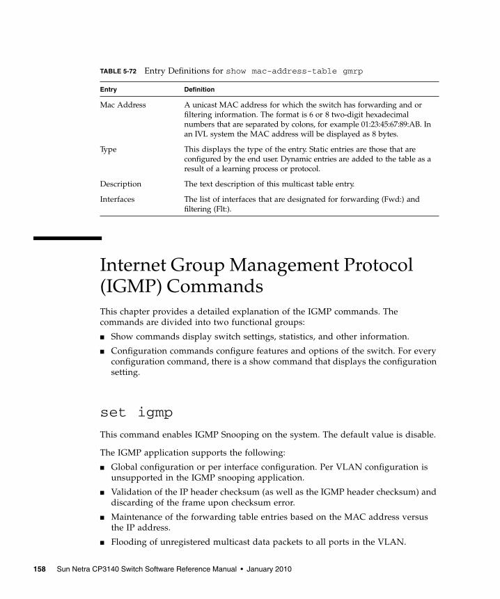
Internet Group Management Protocol(IGMP) CommandsThis chapter provides a detailed explanation of the IGMP commands. Thecommands are divided into two functional groups:
■ Show commands display switch settings, statistics, and other information.
■ Configuration commands configure features and options of the switch. For everyconfiguration command, there is a show command that displays the configurationsetting.
set igmp
This command enables IGMP Snooping on the system. The default value is disable.
The IGMP application supports the following:
■ Global configuration or per interface configuration. Per VLAN configuration isunsupported in the IGMP snooping application.
■ Validation of the IP header checksum (as well as the IGMP header checksum) anddiscarding of the frame upon checksum error.
■ Maintenance of the forwarding table entries based on the MAC address versusthe IP address.
■ Flooding of unregistered multicast data packets to all ports in the VLAN.
TABLE 5-72 Entry Definitions for show mac-address-table gmrp
Entry Definition
Mac Address A unicast MAC address for which the switch has forwarding and orfiltering information. The format is 6 or 8 two-digit hexadecimalnumbers that are separated by colons, for example 01:23:45:67:89:AB. Inan IVL system the MAC address will be displayed as 8 bytes.
Type This displays the type of the entry. Static entries are those that areconfigured by the end user. Dynamic entries are added to the table as aresult of a learning process or protocol.
Description The text description of this multicast table entry.
Interfaces The list of interfaces that are designated for forwarding (Fwd:) andfiltering (Flt:).
158 Sun Netra CP3140 Switch Software Reference Manual • January 2010
Following are the format and mode for the set igmp command.
■ Format – set igmp
■ Mode – Global Config
no set igmp
This command disables IGMP Snooping on the system.
■ Format – no set igmp
■ Mode – Global Config
set igmp
This command enables IGMP Snooping on a selected interface. If an interface whichhas IGMP Snooping enabled is enabled for routing or is enlisted as a member of aport-channel (LAG), IGMP Snooping functionality will be disabled on that interface.IGMP Snooping functionality will subsequently be re-enabled if routing is disabledor port-channel (LAG) membership is removed from an interface that has IGMPSnooping enabled.
■ Default – Disabled
■ Format – set igmp
■ Mode – Interface Config
no set igmp
This command disables IGMP Snooping on a selected interface.
■ Format – no set igmp
■ Mode – Interface Config
Chapter 5 Switching Commands 159

set igmp groupmembershipinterval
This command sets the IGMP Group Membership Interval time on the system. TheGroup Membership Interval time is the amount of time in seconds that a switch willwait for a report from a particular group on a particular interface before deleting theinterface from the entry. This value must be greater than the IGMP MaximumResponse time value. The range is 2 to 3600 seconds.
■ Default – 260
■ Format – set igmp groupmembershipinterval <2-3600>
■ Mode – Global Config
no set igmp groupmembershipinterval
This command sets the IGMP Group Membership Interval time on the system to 260seconds.
■ Format – no set igmp groupmembershipinterval
■ Mode – Global Config
set igmp interfacemode all
This command enables IGMP Snooping on all interfaces. If an interface which hasIGMP Snooping enabled is enabled for routing or is enlisted as a member of a port-channel (LAG), IGMP Snooping functionality will be disabled on that interface.IGMP Snooping functionality will subsequently be re-enabled if routing is disabledor port-channel (LAG) membership is removed from an interface that has IGMPSnooping enabled.
■ Default – disabled
■ Format – set igmp interfacemode all
■ Mode – Global Config
no set igmp interfacemode all
This command disables IGMP Snooping on all interfaces.
■ Format – no set igmp interfacemode all
■ Mode – Global Config
160 Sun Netra CP3140 Switch Software Reference Manual • January 2010

set igmp maxresponse
This command sets the IGMP Maximum Response time on the system. TheMaximum Response time is the amount of time in seconds that a switch will waitafter sending a query on an interface because it did not receive a report for aparticular group in that interface. This value must be less than the IGMP QueryInterval time value. The range is 1 to 3599 seconds.
■ Default – 10
■ Format – set igmp maxresponse <1-3599>
■ Mode – Global Config
no set igmp maxresponse
This command sets the IGMP Maximum Response time on the system to 10 seconds.
■ Format – no set igmp maxresponse
■ Mode – Global Config
set igmp mcrtrexpiretime
This command sets the Multicast Router Present Expiration time on the system. Thisis the amount of time in seconds that a switch will wait for a query to be received onan interface before the interface is removed from the list of interfaces with multicastrouters attached. The range is 0 to 3600 seconds. A value of 0 indicates an infinitetimeout; that is, no expiration.
■ Default – 0
■ Format – set igmp mcrtrexpiretime <0-3600>
■ Mode – Global Config
no set igmp mcrtrexpiretime
This command sets the Multicast Router Present Expiration time on the system to 0.A value of 0 indicates an infinite timeout; that is, no expiration.
■ Format – no set igmp mcrtrexpiretime
■ Mode – Global Config
Chapter 5 Switching Commands 161
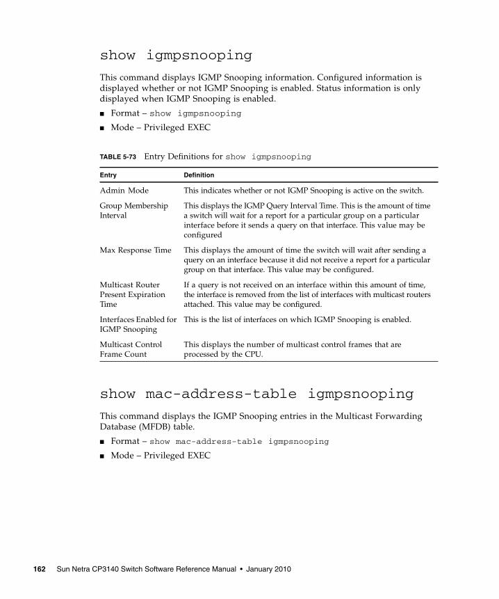
show igmpsnooping
This command displays IGMP Snooping information. Configured information isdisplayed whether or not IGMP Snooping is enabled. Status information is onlydisplayed when IGMP Snooping is enabled.
■ Format – show igmpsnooping
■ Mode – Privileged EXEC
show mac-address-table igmpsnooping
This command displays the IGMP Snooping entries in the Multicast ForwardingDatabase (MFDB) table.
■ Format – show mac-address-table igmpsnooping
■ Mode – Privileged EXEC
TABLE 5-73 Entry Definitions for show igmpsnooping
Entry Definition
Admin Mode This indicates whether or not IGMP Snooping is active on the switch.
Group MembershipInterval
This displays the IGMP Query Interval Time. This is the amount of timea switch will wait for a report for a particular group on a particularinterface before it sends a query on that interface. This value may beconfigured
Max Response Time This displays the amount of time the switch will wait after sending aquery on an interface because it did not receive a report for a particulargroup on that interface. This value may be configured.
Multicast RouterPresent ExpirationTime
If a query is not received on an interface within this amount of time,the interface is removed from the list of interfaces with multicast routersattached. This value may be configured.
Interfaces Enabled forIGMP Snooping
This is the list of interfaces on which IGMP Snooping is enabled.
Multicast ControlFrame Count
This displays the number of multicast control frames that areprocessed by the CPU.
162 Sun Netra CP3140 Switch Software Reference Manual • January 2010
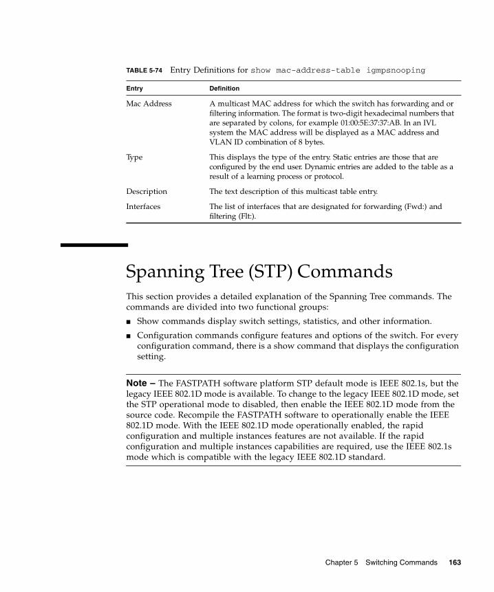
Spanning Tree (STP) CommandsThis section provides a detailed explanation of the Spanning Tree commands. Thecommands are divided into two functional groups:
■ Show commands display switch settings, statistics, and other information.
■ Configuration commands configure features and options of the switch. For everyconfiguration command, there is a show command that displays the configurationsetting.
Note – The FASTPATH software platform STP default mode is IEEE 802.1s, but thelegacy IEEE 802.1D mode is available. To change to the legacy IEEE 802.1D mode, setthe STP operational mode to disabled, then enable the IEEE 802.1D mode from thesource code. Recompile the FASTPATH software to operationally enable the IEEE802.1D mode. With the IEEE 802.1D mode operationally enabled, the rapidconfiguration and multiple instances features are not available. If the rapidconfiguration and multiple instances capabilities are required, use the IEEE 802.1smode which is compatible with the legacy IEEE 802.1D standard.
TABLE 5-74 Entry Definitions for show mac-address-table igmpsnooping
Entry Definition
Mac Address A multicast MAC address for which the switch has forwarding and orfiltering information. The format is two-digit hexadecimal numbers thatare separated by colons, for example 01:00:5E:37:37:AB. In an IVLsystem the MAC address will be displayed as a MAC address andVLAN ID combination of 8 bytes.
Type This displays the type of the entry. Static entries are those that areconfigured by the end user. Dynamic entries are added to the table as aresult of a learning process or protocol.
Description The text description of this multicast table entry.
Interfaces The list of interfaces that are designated for forwarding (Fwd:) andfiltering (Flt:).
Chapter 5 Switching Commands 163

spanning-tree max-hops
This command sets the MSTP Max Hops parameter to a new value for the commonand internal spanning tree. The max-hops value is in a range of 1 to 127.
■ Default – 20
■ Format – spanning-tree max-hops <1-127>
■ Mode – Global Config
no spanning-tree max-hops
This command sets the Bridge Max Hops parameter for the common and internalspanning tree to the default value.
■ Format – no spanning-tree max-hops
■ Mode – Global Config
spanning-tree
This command sets the spanning-tree operational mode to enabled.
■ Default – disabled
■ Format – spanning-tree
■ Mode – Global Config
no spanning-tree
This command sets the spanning-tree operational mode to disabled. While disabled,the spanning-tree configuration is retained and can be changed, but is not activated.
■ Format – no spanning-tree
■ Mode – Global Config
164 Sun Netra CP3140 Switch Software Reference Manual • January 2010
spanning-tree configuration name
This command sets the Configuration Identifier Name for use in identifying theconfiguration that this switch is currently using. The <name> is a string of at most 32characters.
■ Default – The base MAC address displayed using hexadecimal notation as specifiedin IEEE 802 standard.
■ Format – spanning-tree configuration name <name>
■ Mode – Global Config
no spanning-tree configuration name
This command resets the Configuration Identifier Name to its default.
■ Format – no spanning-tree configuration name
■ Mode – Global Config
spanning-tree configuration revision
This command sets the Configuration Identifier Revision Level for use in identifyingthe configuration that this switch is currently using. The Configuration IdentifierRevision Level is a number in the range of 0 to 65535.
■ Default – 0
■ Format – spanning-tree configuration revision <0-65535>
■ Mode – Global Config
no spanning-tree configuration revision
This command sets the Configuration Identifier Revision Level for use in identifyingthe configuration that this switch is currently using to the default value, 0.
■ Format – no spanning-tree configuration revision
■ Mode – Global Config
Chapter 5 Switching Commands 165

spanning-tree edgeport
This command specifies that this port is an Edge Port within the common andinternal spanning tree. This will allow this port to transition to Forwarding Statewithout delay.
■ Format – spanning-tree edgeport
■ Mode – Interface Config
no spanning-tree edgeport
This command specifies that this port is not an Edge Port within the common andinternal spanning tree.
■ Format – no spanning-tree edgeport
■ Mode – Interface Config
spanning-tree forceversion
This command sets the Force Protocol Version parameter to a new value. The ForceProtocol Version can be one of the following:
■ 802.1d - ST BPDUs are transmitted rather than MST BPDUs (IEEE 802.1dfunctionality supported)
■ 802.1w - RST BPDUs are transmitted rather than MST BPDUs (IEEE 802.1wfunctionality supported)
■ 802.1s - MST BPDUs are transmitted (IEEE 802.1s functionality supported)
Following are the format and mode for the spanning-tree forceversioncommand.
■ Default – 802.1s
■ Format – spanning-tree forceversion <802.1d | 802.1w | 802.1s>
■ Mode – Global Config
no spanning-tree forceversion
This command sets the Force Protocol Version parameter to the default value, 802.1s.
■ Format – no spanning-tree forceversion
■ Mode – Global Config
166 Sun Netra CP3140 Switch Software Reference Manual • January 2010
spanning-tree forward-time
This command sets the Bridge Forward Delay parameter to a new value for thecommon and internal spanning tree. The forward-time value is in seconds within arange of 4 to 30, with the value being greater than or equal to "(Bridge Max Age / 2)+ 1".
■ Default – 15
■ Format – spanning-tree forward-time <4-30>
■ Mode – Global Config
no spanning-tree forward-time
This command sets the Bridge Forward Delay parameter for the common andinternal spanning tree to the default value, 15.
■ Format – no spanning-tree forward-time
■ Mode – Global Config
spanning-tree hello-time
This command sets the Admin Hello Time parameter to a new value for the commonand internal spanning tree. The hellotime <value> is in whole seconds within arange of 1 to 10 with the value being less than or equal to "(Bridge Max Age / 2) - 1".
■ Default – 2
■ Format – spanning-tree hello-time <1-10>
■ Mode – Interface Config
no spanning-tree hello-time
This command sets the admin Hello Time parameter for the common and internalspanning tree to the default value.
■ Format – no spanning-tree hello-time
■ Mode – Interface Config
Chapter 5 Switching Commands 167

spanning-tree max-age
This command sets the Bridge Max Age parameter to a new value for the commonand internal spanning tree. The max-age value is in seconds within a range of 6 to40, with the value being less than or equal to "2 times - (Bridge Forward Delay - 1)".
■ Default – 20
■ Format – spanning-tree max-age <6-40>
■ Mode – Global Config
no spanning-tree max-age
This command sets the Bridge Max Age parameter for the common and internalspanning tree to the default value, 20.
■ Format – no spanning-tree max-age
■ Mode – Global Config
spanning-tree mst instance
This command adds a multiple spanning tree instance to the switch. The instance<mstid> is a number within a range of 1 to 4021, that corresponds to the newinstance ID to be added. The maximum number of multiple instances supported byFASTPATH is 4.
■ Format – spanning-tree mst instance <mstid>
■ Mode – Global Config
no spanning-tree mst instance
This command removes a multiple spanning tree instance from the switch andreallocates all VLANs allocated to the deleted instance to the common and internalspanning tree. The instance <mstid> is a number that corresponds to the desiredexisting multiple spanning tree instance to be removed.
■ Format – no spanning-tree mst instance <mstid>
■ Mode – Global Config
168 Sun Netra CP3140 Switch Software Reference Manual • January 2010

spanning-tree mst priority
This command sets the bridge priority for a specific multiple spanning tree instance.The instance <mstid> is a number that corresponds to the desired existing multiplespanning tree instance. The priority value is a number within a range of 0 to 61440 inincrements of 4096.
If 0 (defined as the default CIST ID) is passed as the <mstid>, then this command setsthe Bridge Priority parameter to a new value for the common and internal spanning tree.The bridge priority value again is a number within a range of 0 to 61440. The twelve leastsignificant bits will be masked according to the 802.1s specification. This will cause thepriority to be rounded down to the next lower valid priority.
■ Default – 32768
■ Format – spanning-tree mst priority <mstid> <0-61440>
■ Mode – Global Config
no spanning-tree mst priority
This command sets the bridge priority for a specific multiple spanning tree instanceto the default value, 32768. The instance <mstid> is a number that corresponds tothe desired existing multiple spanning tree instance.
If 0 (defined as the default CIST ID) is passed as the <mstid>, then this commandsets the Bridge Priority parameter for the common and internal spanning tree to thedefault value, 32768.
■ Format – spanning-tree mst priority <mstid>
■ Mode – Global Config
spanning-tree mst vlan
This command adds an association between a multiple spanning tree instance and aVLAN. The VLAN will no longer be associated with the common and internalspanning tree. The instance <mstid> is a number that corresponds to the desiredexisting multiple spanning tree instance. The <vlanid> corresponds to an existingVLAN ID.
■ Format – spanning-tree mst vlan <mstid> <vlanid>
■ Mode – Global Config
Chapter 5 Switching Commands 169
no spanning-tree mst vlan
This command removes an association between a multiple spanning tree instanceand a VLAN. The VLAN will again be associated with the common and internalspanning tree. The instance <mstid> is a number that corresponds to the desiredexisting multiple spanning tree instance. The <vlanid> corresponds to an existingVLAN ID.
■ Format – no spanning-tree mst vlan <mstid> <vlanid>
■ Mode – Global Config
spanning-tree port mode
This command sets the Administrative Switch Port State for this port to enabled.
■ Default – disabled
■ Format – spanning-tree port mode
■ Mode – Interface Config
no spanning-tree port mode
This command sets the Administrative Switch Port State for this port to disabled.
■ Format – no spanning-tree port mode
■ Mode – Interface Config
spanning-tree port mode all
This command sets the Administrative Switch Port State for all ports to enabled.
■ Default – disabled
■ Format – spanning-tree port mode all
■ Mode – Global Config
no spanning-tree port mode all
This command sets the Administrative Switch Port State for all ports to disabled.
■ Format – no spanning-tree port mode all
■ Mode – Global Config
170 Sun Netra CP3140 Switch Software Reference Manual • January 2010

spanning-tree
This command sets the STP mode for a specific port-channel (LAG). This is the valuespecified for STP Mode on the Port Configuration Menu. 802.1D mode is the default.The interface is a logical unit, slot and port slot and port for a configured port-channel. The all option sets all configured port-channels (LAGs) with the sameoption.
■ Format – spanning-tree {<logical slot/port> | all | <off | 802.1d| fast>}
■ Mode – Global Config
The mode is one of the following.
spanning-tree bpdumigrationcheck
This command enables BPDU migration check on a given interface. The all optionenables BPDU migration check on all interfaces.
■ Format – spanning-tree bpdumigrationcheck {<slot/port> | all}
■ Mode – Global Config
no spanning-tree bpdumigrationcheck
This command disables BPDU migration check on a given interface. The all optiondisables BPDU migration check on all interfaces.
■ Format – no spanning-tree bpdumigrationcheck {<slot/port> |all}
■ Mode – Global Config
TABLE 5-75 Mode Settings for spanning-tree
Entry Description
802.1d IEEE 802.1D-compliant STP mode is used
fast Fast STP mode is used
off STP is turned off
Chapter 5 Switching Commands 171
show spanning-tree
This command displays spanning tree settings for the common and internalspanning tree, when the optional parameter “brief” is not included in the command.The following details are displayed.
■ Format – show spanning-tree <brief>
■ Mode – Privileged EXEC and User EXEC
TABLE 5-76 Entry Definitions for show spanning-tree Without brief Parameter
Entry Definition
Bridge Priority Specifies the bridge priority for the spanning tree.
Bridge Identifier The bridge identifier for the selected instance.
Time Since TopologyChange
The time in seconds since the topology last changed.
Topology ChangeCount
Number of times the topology has changed.
Topology Change inprogress
Boolean value of the Topology Change parameter for the switchindicating if a topology change is in progress on any port assigned tothe common and internal spanning tree.
Designated Root The bridge identifier of the root bridge. It is derived from the bridgepriority and the base MAC address of the bridge.
Root Path Cost Value of the Root Path Cost parameter for the common and internalspanning tree.
Root Port Identifier Port to access the Designated Root.
Bridge Max Age Specifies the bridge maximum age for the spanning tree.
Bridge ForwardingDelay
Specifies the time spent in “Listening and Learning” mode beforeforwarding packets. Bridge Forwarding Delay must be greater orequal to “(Bridge Max Age/2) + 1”. The time range is from 4 secondsto 30 seconds. The default value is 15.
Hello Time Configured value of the parameter for common spanning tree.
Bridge Hold Time Minimum time between transmission of Configuration Bridge ProtocolData Units (BPDUs)
CST Regional Root Bridge Identifier of the common spanning tree regional root. It isderived using the bridge priority and the base MAC address of thebridge.
172 Sun Netra CP3140 Switch Software Reference Manual • January 2010

When the “brief” optional parameter is included, this command displays spanningtree settings for the bridge. In this case, the following details are displayed.
show spanning-tree interface
This command displays the settings and parameters for a specific switch port withinthe common and internal spanning tree. The <slot/port> is the desired switch port.The following details are displayed on execution of the command.
■ Format – show spanning-tree interface <slot/port>
■ Mode – Privileged EXEC and User EXEC
Regional Root PathCost
Path cost to the common spanning tree Regional Root.
Associated FIDs List of forwarding database identifiers currently associated with thisinstance.
Associated VLANs List of VLAN IDs currently associated with this instance.
TABLE 5-77 Entry Definitions for show spanning-tree With brief Parameter
Entry Definition
Bridge Priority Specifies the bridge priority for the spanning tree.
Bridge Identifier The bridge identifier for the selected instance.
Bridge Max Age Specifies the bridge maximum age for the spanning tree.
Hello Time Configured value of the parameter for the common spanning tree.
Bridge ForwardingDelay
Specifies the time spent in “Listening and Learning” mode beforeforwarding packets. Bridge Forwarding Delay must be greater orequal to “(Bridge Max Age/2) + 1”. The time range is from 4 secondsto 30 seconds. The default value is 15.
Bridge Hold Time Minimum time between transmission of Configuration BridgeProtocol Data Units (BPDUs).
TABLE 5-76 Entry Definitions for show spanning-tree Without brief Parameter
Entry Definition
Chapter 5 Switching Commands 173

show spanning-tree mst detailed
This command displays settings and parameters for the specified multiple spanningtree instance. The instance <mstid> is a number that corresponds to the desiredexisting multiple spanning tree instance ID. The following details are displayed.
■ Format – show spanning-tree mst detailed <mstid>
■ Mode – Privileged EXEC and User EXEC
TABLE 5-78 Entry Definitions for show spanning-tree interface
Entry Definition
Port Mode Enabled or disabled.
Port Up Time SinceCounters LastCleared
Time since port was reset, displayed in days, hours, minutes, andseconds.
STP BPDUsTransmitted
Spanning Tree Protocol Bridge Protocol Data Units sent
STP BPDUs Received Spanning Tree Protocol Bridge Protocol Data Units received.
RST BPDUsTransmitted
Rapid Spanning Tree Protocol Bridge Protocol Data Units sent
RST BPDUs Received Rapid Spanning Tree Protocol Bridge Protocol Data Units received.
MSTP BPDUsTransmitted
Multiple Spanning Tree Protocol Bridge Protocol Data Units sent
MSTP BPDUsReceived
Multiple Spanning Tree Protocol Bridge Protocol Data Units received.
TABLE 5-79 Entry Definitions for show spanning-tree mst detailed
Entry Definition
MST Instance ID The ID of the MST being created.
MST Bridge Priority The bridge priority for the MST instance selected.
Time Since TopologyChange
The time in seconds since the topology changed.
Topology ChangeCount
Number of times the topology has changed for this multiple spanningtree instance.
Topology Change inProgress
Value of the Topology Change parameter for the multiple spanning treeinstance.
174 Sun Netra CP3140 Switch Software Reference Manual • January 2010

show spanning-tree mst port detailed
This command displays the detailed settings and parameters for a specific switchport within a particular multiple spanning tree instance. The instance <mstid> is anumber that corresponds to the desired existing multiple spanning tree instance. The<slot/port> is the desired switch port.
■ Format – show spanning-tree mst port detailed <mstid> <slot/port>
■ Mode – Privileged EXEC and User EXEC
Designated Root Identifier of the Regional Root for this multiple spanning tree instance.
Root Path Cost Path Cost to the Designated Root for this multiple spanning treeinstance.
Root Port Identifier Port to access the Designated Root for this multiple spanning treeinstance.
Associated FIDs List of forwarding database identifiers associated with this instance.
Associated VLANs List of VLAN IDs associated with this instance.
TABLE 5-80 Entry Definitions for show spanning-tree mst port detailed
Entry Definition
MST Instance ID The ID of the MST instance.
Port Identifier The port identifier for the specified port within the spanning tree.
Port Priority The priority for a particular port within the selected MST instance.
Port Forwarding State Current spanning tree state of this port
Port Role Each MST Bridge Port that is enabled is assigned a Port Role for eachspanning tree.
Port Path Cost Configured value of the Internal Port Path Cost parameter
Designated Root The Identifier of the designated root for this port.
Designated Port Cost Path Cost offered to the LAN by the Designated Port
Designated Bridge Bridge Identifier of the bridge with the Designated Port.
Designated PortIdentifier
Port on the Designated Bridge that offers the lowest cost to the LAN.
TABLE 5-79 Entry Definitions for show spanning-tree mst detailed
Entry Definition
Chapter 5 Switching Commands 175

If 0 (defined as the default CIST ID) is passed as the <mstid>, then this commanddisplays the settings and parameters for a specific switch port within the commonand internal spanning tree. The <slot/port> is the desired switch port. In this case,the following are displayed.
TABLE 5-81 Entry Definitions for show spanning-tree mst port detailed if 0 isPassed as the <mtsid>
Entry Definition
Port Identifier The port identifier for this port within the CST.
Port Priority The priority of the port within the CST.
Port Forwarding State The forwarding state of the port within the CST.
Port Role The role of the specified interface within the CST.
Port Path Cost The configured path cost for the specified interface.
Designated Root Identifier of the designated root for this port within the CST.
Designated Port Cost Path Cost offered to the LAN by the Designated Port.
Designated Bridge The bridge containing the designated port
Designated PortIdentifier
Port on the Designated Bridge that offers the lowest cost to the LAN
Topology ChangeAcknowledgement
Value of flag in next Configuration Bridge Protocol Data Unit (BPDU)transmission indicating if a topology change is in progress for thisport.
Hello Time The hello time in use for this port.
Edge Port The configured value indicating if this port is an edge port.
Edge Port Status The derived value of the edge port status. True if operating as an edgeport; false otherwise.
Point To Point MACStatus
Derived value indicating if this port is part of a point to point link.
CST Regional Root The regional root identifier in use for this port.
CST Port Cost The configured path cost for this port.
176 Sun Netra CP3140 Switch Software Reference Manual • January 2010

show spanning-tree mst port summary
This command displays the settings of one or all ports within the specified multiplespanning tree instance. The parameter <mstid> indicates a particular MST instance.The parameter {<slot/port> | all} indicates the desired switch port or all ports.
If 0 (defined as the default CIST ID) is passed as the <mstid>, then the statussummary is displayed for one or all ports within the common and internal spanningtree.
■ Format – show spanning-tree mst port summary <mstid> {<slot/port>| all}
■ Mode – Privileged EXEC and User EXEC
show spanning-tree mst summary
This command displays summary information about all multiple spanning treeinstances in the switch. On execution, the following details are displayed.
■ Format – show spanning-tree mst summary
■ Mode – Privileged EXEC and User EXEC
TABLE 5-82 Entry Definitions for show spanning-tree mst port summary
Entry Definition
MST Instance ID The MST instance associated with this port.
Slot/Port Valid slot and port number separated by forward slashes.
Type Currently not used.
STP State The forwarding state of the port in the specified spanning treeinstance
Port Role The role of the specified port within the spanning tree.
Link Status The operational status of the link. Possible values are “Up” or“Down”.
Link Trap The link trap configuration for the specified interface.
TABLE 5-83 Entry Definitions for show spanning-tree mst summary
Entry Definition
MST Instance ID List List of multiple spanning trees IDs currently configured.
Chapter 5 Switching Commands 177

For each MSTID, the following will be displayed.
show spanning-tree summary
This command displays spanning tree settings and parameters for the switch. Thefollowing details are displayed on execution of the command.
■ Format – show spanning-tree summary
■ Mode – Privileged EXEC and User EXEC
TABLE 5-84 Entry Definitions for show spanning-tree mst summary for EachMTSID
Display Definition
Associated FIDs List of forwarding database identifiers associated with this instance.
Associated VLANs List of VLAN IDs associated with this instance.
TABLE 5-85 Entry Definitions for show spanning-tree summary
Entry Definition
Spanning TreeAdminmode
Enabled or disabled.
Spanning Tree Version Version of 802.1 currently supported (IEEE 802.1s, IEEE 802.1w, orIEEE 802.1d) based upon the Force Protocol Version parameter.
Configuration Name Identifier used to identify the configuration currently being used.
ConfigurationRevision Level
Identifier used to identify the configuration currently being used.
Configuration DigestKey
Identifier used to identify the configuration currently being used.
MST Instances List of all multiple spanning tree instances configured on the switch
178 Sun Netra CP3140 Switch Software Reference Manual • January 2010

show spanning-tree vlan
This command displays the association between a VLAN and a multiple spanningtree instance. The<vlanid> corresponds to an existing VLAN ID.
■ Format – show spanning-tree vlan <vlanid>
■ Mode – Privileged EXEC and User EXEC
Layer 2 Failover CommandsThis section describes the Layer 2 failover commands. Layer 2 failover functionalitydisables configured server ports in case a monitored uplink port or port channelfails. This failover is designed to be used with NIC teaming or bonding to facilitateuplink redundancy without the need for Layer 2 connections between Fabric/Baseswitches.
Layer 2 failover incorparates the track object features of VRRP, using the objectstatus to determine uplink status to the switch. For commands and configurationguidelines, see “VRRP Tracking Commands” on page 194.
failover track
This command configures the interface to track the configured monitor and todisable the interface if the monitor status is down. The number at the end of thecommand corresponds to the track object number listed under the globalconfiguration.
TABLE 5-86 Entry Definitions for show spanning-tree vlan
Entry Definition
Associated Instance Identifier for the associated multiple spanning tree instance or "CST"if associated with the common and internal spanning tree
Default disabled
Format Failover track [ <1-255> ]
Mode Interface Config
Chapter 5 Switching Commands 179

show track failover
Show status of single or all interfaces configured with the failover track command.
Link Aggregation (LAG)/Port-Channel(802.3AD) CommandsThis section provides a detailed explanation of the LAG commands. The commandsare divided into two functional groups:
■ Show commands display switch settings, statistics, and other information.
■ Configuration commands configure features and options of the switch. For everyconfiguration command, there is a show command that displays the configurationsetting.
port-channel staticcapability
This command enables the support of port-channels (static link aggregations -LAGs) on the device. By default, the static capability for all port-channels isdisabled.
■ Default – disabled
Format show track failover [ interface <0/#> ] [all]
Mode Privileged EXEC
TABLE 5-87 Entry Definitions for show track failover
Entry Definition
Interface Displays interfaces configured with failover track command.
Track Num Displays the tracking object number associated with the listed interface.
Track Status Displays the status of the tracking object (up or down).
Interface Status Displays the status of the interface configured with the failover trackcommand.• Up indicates the tracked object is up and the interface is connected and
active.• Disabled indicates the tracked object is down and the interface link state
has been disabled.
180 Sun Netra CP3140 Switch Software Reference Manual • January 2010
■ Format – port-channel staticcapability
■ Mode – Global Config
no port-channel staticcapability
This command disables the support of static port-channels (link aggregations -LAGs) on the device.
■ Format – no port-channel staticcapability
■ Mode – Global Config
port lacpmode
This command enables Link Aggregation Control Protocol (LACP) on a port.
■ Default – disabled
■ Format – port lacpmode
■ Mode – Interface Config
no port lacpmode
This command disables Link Aggregation Control Protocol (LACP) on a port.
■ Format – no port lacpmode
■ Mode – Interface Config
port lacpmode all
This command enables Link Aggregation Control Protocol (LACP) on all ports.
■ Format – port lacpmode all
■ Mode – Global Config
no port lacpmode all
This command disables Link Aggregation Control Protocol (LACP) on all ports.
■ Format – no port lacpmode all
■ Mode – Global Config
Chapter 5 Switching Commands 181

port-channel
This command configures a new port-channel (LAG) and generates a logicalslot/port number for the port-channel. The <name> field is a character string whichallows the dash '-' character as well as alphanumeric characters. Display this numberusing the “show port-channel”.
Note – Before including a port in a port-channel, set the port physical mode (see“speed” on page 73).
■ Format – port-channel <name>
■ Mode – Global Config
no port-channel
This command deletes a port-channel (LAG).
■ Format – no port-channel <name>
■ Mode – Global Config
port-channel adminmode all
This command enables a port-channel (LAG). The interface is a logical slot/port fora configured port-channel. The option all sets every configured port-channel withthe same administrative mode setting.
■ Format – port-channel adminmode all
■ Mode – Global Config
no port-channel adminmode
This command disables a port-channel (LAG). The interface is a logical slot/port fora configured port- channel. The option all sets every configured port-channel withthe same administrative mode setting.
■ Format – no port-channel adminmode all
■ Mode – Global Config
182 Sun Netra CP3140 Switch Software Reference Manual • January 2010

port-channel linktrap
This command enables link trap notifications for the port-channel (LAG). Theinterface is a logical slot/ port for a configured port-channel. The option all setsevery configured port-channel with the same administrative mode setting.
■ Default – enabled
■ Format – port-channel linktrap {<logical slot/port> | all}
■ Mode – Global Config
no port-channel linktrap
This command disables link trap notifications for the port-channel (LAG). Theinterface is a logical unit, slot and port slot and port for a configured port-channel.The option all sets every configured port-channel with the same administrativemode setting.
■ Format – no port-channel linktrap {<logical slot/port> | all]
■ Mode – GlobalConfig
port-channel name
This command defines a name for the port-channel (LAG). The interface is a logicalslot/port for a configured port-channel, and name is an alphanumeric string up to15 characters. This command is used to modify the name that was associated withthe port-channel when it was created.
■ Format – port-channel name {<logical slot/port> | all | <name>}
■ Mode – Global Config
show port-channel brief
This command displays the static capability of all port-channels (LAGs) on thedevice as well as a summary of individual port-channels.
■ Format – show port-channel brief
■ Mode – Privileged EXEC and User EXEC
Chapter 5 Switching Commands 183
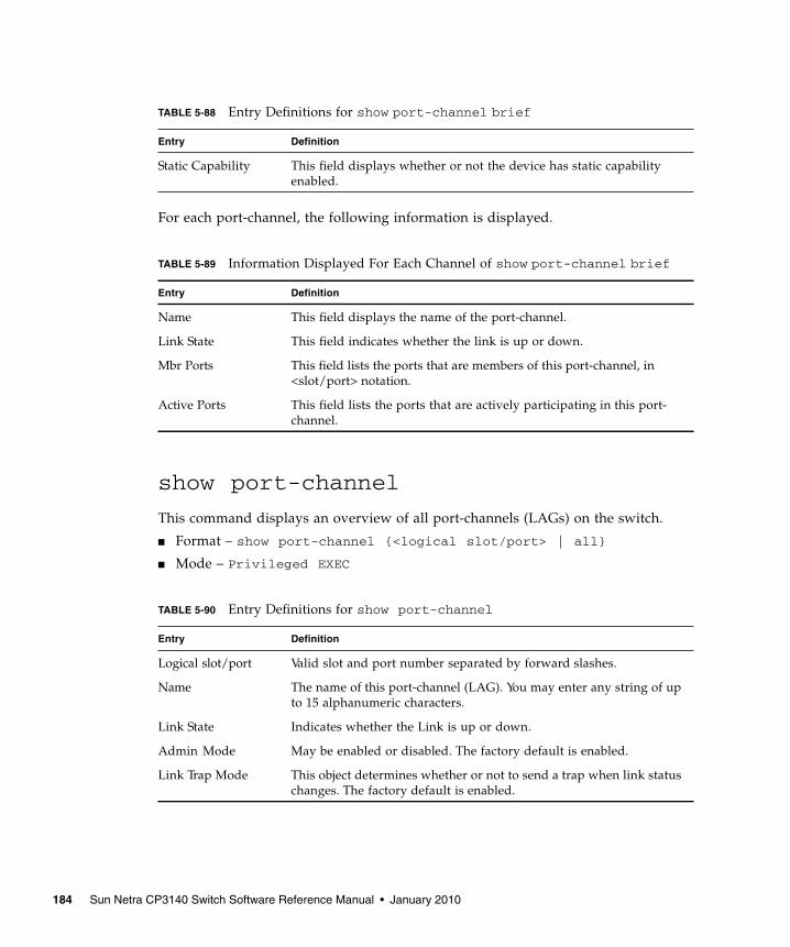
For each port-channel, the following information is displayed.
show port-channel
This command displays an overview of all port-channels (LAGs) on the switch.
■ Format – show port-channel {<logical slot/port> | all}
■ Mode – Privileged EXEC
TABLE 5-88 Entry Definitions for show port-channel brief
Entry Definition
Static Capability This field displays whether or not the device has static capabilityenabled.
TABLE 5-89 Information Displayed For Each Channel of show port-channel brief
Entry Definition
Name This field displays the name of the port-channel.
Link State This field indicates whether the link is up or down.
Mbr Ports This field lists the ports that are members of this port-channel, in<slot/port> notation.
Active Ports This field lists the ports that are actively participating in this port-channel.
TABLE 5-90 Entry Definitions for show port-channel
Entry Definition
Logical slot/port Valid slot and port number separated by forward slashes.
Name The name of this port-channel (LAG). You may enter any string of upto 15 alphanumeric characters.
Link State Indicates whether the Link is up or down.
Admin Mode May be enabled or disabled. The factory default is enabled.
Link Trap Mode This object determines whether or not to send a trap when link statuschanges. The factory default is enabled.
184 Sun Netra CP3140 Switch Software Reference Manual • January 2010
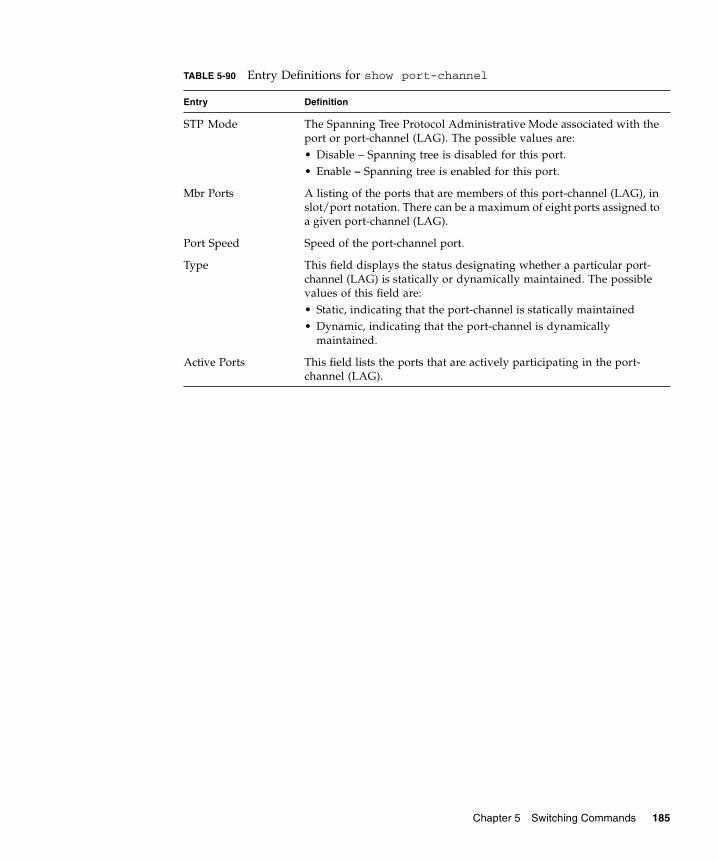
STP Mode The Spanning Tree Protocol Administrative Mode associated with theport or port-channel (LAG). The possible values are:• Disable – Spanning tree is disabled for this port.• Enable – Spanning tree is enabled for this port.
Mbr Ports A listing of the ports that are members of this port-channel (LAG), inslot/port notation. There can be a maximum of eight ports assigned toa given port-channel (LAG).
Port Speed Speed of the port-channel port.
Type This field displays the status designating whether a particular port-channel (LAG) is statically or dynamically maintained. The possiblevalues of this field are:• Static, indicating that the port-channel is statically maintained• Dynamic, indicating that the port-channel is dynamically
maintained.
Active Ports This field lists the ports that are actively participating in the port-channel (LAG).
TABLE 5-90 Entry Definitions for show port-channel
Entry Definition
Chapter 5 Switching Commands 185

186 Sun Netra CP3140 Switch Software Reference Manual • January 2010

CHAPTER 6
Quality of Service Commands
This chapter provides a detailed explanation of the Quality of Service (QoS)commands. The following QoS commands are available in the FASTPATH softwareQoS module.
The commands are divided into these different groups:
■ Show commands are used to display device settings, statistics and otherinformation.
■ Configuration Commands are used to configure features and options of theswitch. For every configuration command there is a show command that willdisplay the configuration setting.
187
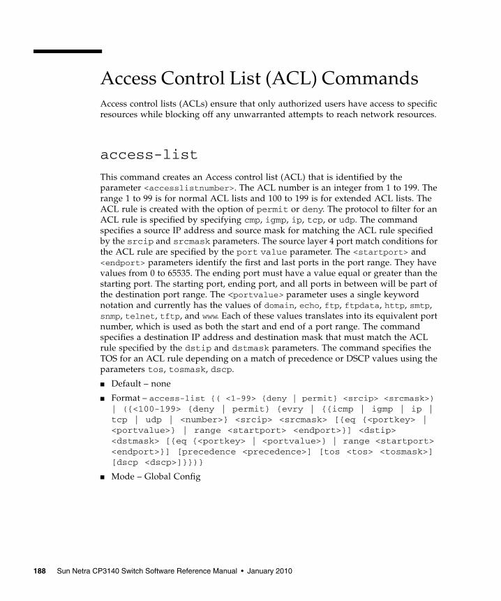
Access Control List (ACL) CommandsAccess control lists (ACLs) ensure that only authorized users have access to specificresources while blocking off any unwarranted attempts to reach network resources.
access-list
This command creates an Access control list (ACL) that is identified by theparameter <accesslistnumber>. The ACL number is an integer from 1 to 199. Therange 1 to 99 is for normal ACL lists and 100 to 199 is for extended ACL lists. TheACL rule is created with the option of permit or deny. The protocol to filter for anACL rule is specified by specifying cmp, igmp, ip, tcp, or udp. The commandspecifies a source IP address and source mask for matching the ACL rule specifiedby the srcip and srcmask parameters. The source layer 4 port match conditions forthe ACL rule are specified by the port value parameter. The <startport> and<endport> parameters identify the first and last ports in the port range. They havevalues from 0 to 65535. The ending port must have a value equal or greater than thestarting port. The starting port, ending port, and all ports in between will be part ofthe destination port range. The <portvalue> parameter uses a single keywordnotation and currently has the values of domain, echo, ftp, ftpdata, http, smtp,snmp, telnet, tftp, and www. Each of these values translates into its equivalent portnumber, which is used as both the start and end of a port range. The commandspecifies a destination IP address and destination mask that must match the ACLrule specified by the dstip and dstmask parameters. The command specifies theTOS for an ACL rule depending on a match of precedence or DSCP values using theparameters tos, tosmask, dscp.
■ Default – none
■ Format – access-list {( <1-99> {deny | permit} <srcip> <srcmask>)| ({<100-199> {deny | permit} {evry | {{icmp | igmp | ip |tcp | udp | <number>} <srcip> <srcmask> [{eq {<portkey> |<portvalue>} | range <startport> <endport>}] <dstip><dstmask> [{eq {<portkey> | <portvalue>} | range <startport><endport>}] [precedence <precedence>] [tos <tos> <tosmask>][dscp <dscp>]}})}
■ Mode – Global Config
188 Sun Netra CP3140 Switch Software Reference Manual • January 2010

no access-list
This command deletes an ACL that is identified by the parameter<accesslistnumber> from the system.
■ Format – no access-list <accesslistnumber>
■ Mode – Global Config
ip access-group
This command attaches a specified ACL to an interface.
■ Default – none
■ Format – ip access-group <accesslistnumber> <in | out>
■ Mode – Interface Config
ip access-group all
This command attaches a specified ACL to all interfaces.
■ Default – none
■ Format – ip access-group all <accesslistnumber> <in | out>
■ Mode – Global Config
show ip access-lists
This command displays an Access control list (ACL) and all of the rules that aredefined for the ACL. The <accesslistnumber> is the number used to identify theACL.
■ Format – show ip access-lists <accesslistnumber>
■ Mode – Privileged EXEC and User EXEC
TABLE 6-1 Entry Definitions for show ip access-lists
Entry Definition
Rule Number The number identifier for each rule that is defined for the ACL.
Action The action associated with each rule. The possible values are Permitor Deny.
Protocol The protocol to filter for this rule.
Chapter 6 Quality of Service Commands 189

Bandwidth Provisioning (BP)CommandsThe Bandwidth Provisioning feature enables network providers to deliver varyinglevels of allocated bandwidth to users sharing the same physical interface. Bymapping a subscriber’s traffic profile to a predefined policy and then activelyprovisioning the minimum and maximum bandwidth consumed by that subscriber,the network provider can provide enhanced service offerings to its customers.
bwallocation
This command creates a bandwidth allocation profile. The <name> field is analphanumeric string up to 15 characters. The <name> field also supports the dash“-” character.
Note – The CLI mode is changed to Bwallocation Config when this command issuccessfully executed.
■ Default – none
■ Format – bwallocation <name>
■ Mode – Bwprovisioning Config
Source IP Address The source IP address for this rule.
Source IP Mask The source IP Mask for this rule.
Source Ports The source port range for this rule.
Destination IPAddress
The destination IP address for this rule.
Destination IP Mask The destination IP Mask for this rule.
Destination Ports The destination port range for this rule.
Service Type FieldMatch
Indicates whether an IP DSCP, IP Precedence, or IP TOS matchcondition is specified for this rule.
Service Type FieldValue
Indicates the value specified for the Service Type Field Match (IPDSCP, IP Precedence, or IP TOS).
TABLE 6-1 Entry Definitions for show ip access-lists (Continued)
Entry Definition
190 Sun Netra CP3140 Switch Software Reference Manual • January 2010

no bwallocation
This command deletes a bandwidth allocation profile from the system. The <name>field is the user supplied name associated with the bandwidth allocation profile. Abandwidth allocation profile may not be deleted while it is associated with a trafficclass.
■ Format – no bwallocation <name>
■ Mode – Bwprovisioning Config
bwallocation
This command associates a bandwidth allocation profile with a traffic class. The<bwprofile> parameter must represent a valid bandwidth allocation profile. Thesum of the bandwidth allocation profile minimum bandwidth of all traffic classesassociated with the same interface must not exceed the total bandwidth of theinterface.
There is no restriction on the sum of the maximum bandwidth of all traffic classesattached to the same port. When a traffic class is attached to a port-channel (LAG)interface, the bandwidth allocation profile minimum bandwidth parameter will notbe applicable to the traffic class.
■ Default – none
■ Format – bwallocation <bwprofile>
■ Mode – Traffic-class Config
maxbandwidth
This commands configures the maximum bandwidth for this bandwidth allocationprofile. The bandwidth is specified in Mbps. The <maxbandwidth> parameter willbe a value from 0 to the maximum bandwidth of the interface associated with thisprofile. The bandwidth allocation profile maximum bandwidth must be greater thanor equal to the minimum bandwidth. If this value is set to 0, it will not allow anytraffic for this bandwidth allocation profile.
■ Default – 100
■ Format – maxbandwidth <maxbandwidth>
■ Mode – Bwallocation Config
Chapter 6 Quality of Service Commands 191

no maxbandwidth
This commands resets the maximum bandwidth for this bandwidth allocationprofile to the default value.
■ Format – no maxbandwidth <maxbw>
■ Mode – Bwallocation Config
minbandwidth
This command configures the minimum bandwidth for this bandwidth allocationprofile. The bandwidth is specified in Mbps. The <minbandwidth> parameter willbe a value from 0 to the maximum bandwidth of the interface associated with thisprofile and represents the minimum data rate for this bandwidth allocation profile.
The bandwidth allocation profile minimum bandwidth must be smaller or equal tothe maximum bandwidth.
■ Default – 1
■ Format – minbandwidth <minbandwidth>
no minbandwidth
This command resets the minimum bandwidth for this bandwidth allocation profileto the default value.
■ Format – no minbandwidth
■ Mode – Bwallocation Config
port
This command attaches a specific interface to this traffic class. The <slot/port> mustindicate a valid <slot/port>.
■ Format – port <slot/port>
■ Mode – Interface Config
192 Sun Netra CP3140 Switch Software Reference Manual • January 2010

show bwp-trafficclass detailed
This command displays the traffic class information for the specified traffic class.
■ Format – show bwprovisioning trafficclass detailed <name>
■ Mode – Privileged EXEC
The following attributes are only displayed if there is a Bandwidth Allocation Profileassociated with this traffic class.
show bwp-trafficclass summary
This command displays the traffic class information for all traffic classes in thesystem.
■ Format – show bwp-trafficclass summary
■ Mode – Privileged EXEC and User EXEC
TABLE 6-2 Entry Definitions for show bwp-trafficclass detailed
Entry Definition
Traffic Class Name Displays the user-defined name of this traffic class.
Slot/Port Valid slot and port number separated by forward slashes.
VLAN ID Displays the user-defined VLAN ID with which this traffic class isassociated.
Weight Displays the user-defined weight of this traffic class.
Accept Byte Count Displays the number of packets that were accepted.
Bandwidth AllocationProfile
Displays the bandwidth allocation profile associated with this trafficclass. This field is blank if there is no bandwidth allocation profileassociated with this traffic class.
TABLE 6-3 Entry Definitions for show bwp-trafficclass detailed WithBandwidth Allocation Profile Association
Entry Definition
Minimum Bandwidth Displays the user-defined minimum bandwidth of this traffic class.
Maximum Bandwidth Displays the user-defined maximum bandwidth of this traffic class.
Chapter 6 Quality of Service Commands 193

show bwp-trafficclass allocatedbw
This command displays the bandwidth allocated by traffic classes for the specifiedinterface or all interfaces. The allocated minimum bandwidth cannot exceed theinterface bandwidth, unless the interface is a port-channel (LAG) interface.
■ Format – show bwp-trafficclass allocatedbw {<slot/port> |all}
■ Mode – Privileged EXEC
TABLE 6-4 Entry Definitions for show bwp-trafficclass summary
Entry Definition
Traffic Class Name Displays the user-defined name of this traffic class.
Slot/Port Valid slot and port number separated by forward slashes.
VLAN ID Displays the user-defined VLAN ID with which this traffic class isassociated.
Weight Displays the user-defined weight of this traffic class.
Bandwidth AllocationProfile
Displays the bandwidth allocation profile associated with this trafficclass. This field is blank if there is no bandwidth allocation profileassociated with this traffic class.
TABLE 6-5 Entry Definitions for show bwp-trafficclass allocatedbw
Entry Definition
Slot/Port Valid slot and port number separated by forward slashes.
Allocated MinimumBandwidth
Displays the total minimum bandwidth assigned by traffic classes onthis interface.
Allocated MaximumBandwidth
Displays the total maximum bandwidth assigned by traffic classes onthis interface.
194 Sun Netra CP3140 Switch Software Reference Manual • January 2010
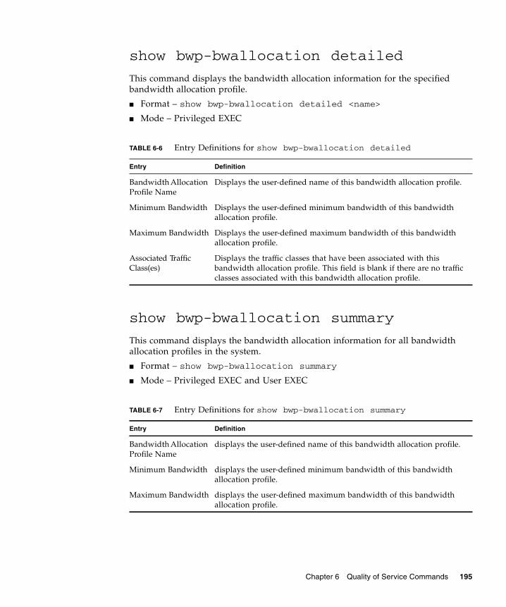
show bwp-bwallocation detailed
This command displays the bandwidth allocation information for the specifiedbandwidth allocation profile.
■ Format – show bwp-bwallocation detailed <name>
■ Mode – Privileged EXEC
show bwp-bwallocation summary
This command displays the bandwidth allocation information for all bandwidthallocation profiles in the system.
■ Format – show bwp-bwallocation summary
■ Mode – Privileged EXEC and User EXEC
TABLE 6-6 Entry Definitions for show bwp-bwallocation detailed
Entry Definition
Bandwidth AllocationProfile Name
Displays the user-defined name of this bandwidth allocation profile.
Minimum Bandwidth Displays the user-defined minimum bandwidth of this bandwidthallocation profile.
Maximum Bandwidth Displays the user-defined maximum bandwidth of this bandwidthallocation profile.
Associated TrafficClass(es)
Displays the traffic classes that have been associated with thisbandwidth allocation profile. This field is blank if there are no trafficclasses associated with this bandwidth allocation profile.
TABLE 6-7 Entry Definitions for show bwp-bwallocation summary
Entry Definition
Bandwidth AllocationProfile Name
displays the user-defined name of this bandwidth allocation profile.
Minimum Bandwidth displays the user-defined minimum bandwidth of this bandwidthallocation profile.
Maximum Bandwidth displays the user-defined maximum bandwidth of this bandwidthallocation profile.
Chapter 6 Quality of Service Commands 195

traffic-class
This command creates a traffic class. The <name> field is an alphanumeric string upto 15 characters. The <name> field also supports the dash “-” character.
Note – The CLI mode is changed to Traffic-Class Config when this command issuccessfully executed.
■ Default – none
■ Format – traffic-class <name>
■ Mode – Bwprovisioning Config
no traffic-class
This command deletes a traffic class from the system. The <name> field is theadministrator supplied name associated with the traffic class. Upon deletion of atraffic, all traffic class association with a bandwidth allocation profile isautomatically removed.
■ Format – no traffic-class <name>
■ Mode – Bwprovisioning Config
vlan
This command associates a VLAN with a traffic class. The <vlanid> field is theVLAN ID for the traffic class within the range of 1 to 4094.
The VLAN parameter can identify an invalid vlan (The vlan does not need to exist inthe system.)
■ Format – vlan <vlanid>
■ Mode – Traffic-class Config
weight
This command configures the priority for this traffic class. The <weight> parameterwill be a value between 1 and 1024.
■ Default – 1
■ Format – weight <weight>
■ Mode – Traffic-class Config
196 Sun Netra CP3140 Switch Software Reference Manual • January 2010
Differentiated Services CommandsThis section contains the CLI commands used for the QoS Differentiated Services(DiffServ) package.
The user configures DiffServ in several stages by specifying:
■ Class
■ Creating and deleting classes
■ Defining match criteria for a class
Note – The only way to remove an individual match criterion from an existing classdefinition is to delete the class and re-create it.
■ Policy
■ Creating and deleting policies
■ Associating classes with a policy
■ Defining policy statements for a policy/class combination
■ Service
■ Adding and removing a policy to/from a directional (i.e., inbound, outbound)interface
Packets are filtered and processed based on defined criteria. The filtering criteria isdefined by a class. The processing is defined by a policy's attributes. Policy attributesmay be defined on a per-class instance basis, and it is these attributes that areapplied when a match occurs.
Packet processing begins by testing the match criteria for a packet. A policy isapplied to a packet when a class match within that policy is found.
Note that the type of class – all, any, or acl – has a bearing on the validity ofmatch criteria specified when defining the class. A class type of 'any' processes itsmatch rules in an ordered sequence; additional rules specified for such a classsimply extend this list. A class type of acl obtains its rule list by interpreting eachACL rule definition at the time the Diffserv class is created. Differences arise whenspecifying match criteria for a class type all, since only one value for eachnon-excluded match field is allowed within a class definition. If a field is alreadyspecified for a class, all subsequent attempts to specify the same field fail, includingthe cases where a field can be specified multiple ways through alternative formats.The exception to this is when the exclude option is specified, in which case thisrestriction does not apply to the excluded fields.
The following class restrictions are imposed by the FASTPATH DiffServ design:
Chapter 6 Quality of Service Commands 197

■ Nested class support limited to:
■ any within any
■ all within all
■ No nested not conditions
■ No nested acl class types
■ Each class contains at most one referenced class
■ Hierarchical service policies not supported in a class definition
■ Access list matched by reference only, and must be sole criterion in a class
■ for example, ACL rules copied as class match criteria at time of class creation,with class type any
■ implicit ACL deny all rule also copied
■ no nesting of class type acl
Regarding nested classes, referred to here as class references, a given class definitioncan contain at most one reference to another class, which can be combined withother match criteria. The referenced class is truly a reference and not a copy, sinceadditions to a referenced class affect all classes that reference it. Changes to any classdefinition currently referenced by any other class must result in valid classdefinitions for all derived classes otherwise the change is rejected. A class referencemay be removed from a class definition.
The user can display summary and detailed information for classes, policies andservices. All configuration information is accessible via the CLI, Web, and SNMPuser interfaces.
diffserv
This command sets the DiffServ operational mode to active. While disabled, theDiffServ configuration is retained and can be changed, but it is not activated. Whenenabled, Diffserv services are activated.
■ Format – diffserv
■ Mode – Global Config
198 Sun Netra CP3140 Switch Software Reference Manual • January 2010
no diffserv
This command sets the DiffServ operational mode to inactive. While disabled, theDiffServ configuration is retained and can be changed, but it is not activated. Whenenabled, Diffserv services are activated.
■ Format – no diffserv
■ Mode – Global Config
Class CommandsThe class command set is used in DiffServ to define:
■ Traffic Classification – Specify Behavior Aggregate (BA), based on DSCP, andMulti-Field (MF) classes of traffic (name, match criteria)
■ Service Levels – Specify the BA forwarding classes / service levels. Conceptually,DiffServ is a two-level hierarchy of classes:
■ Service/PHB
■ Traffic Class
This set of commands consists of class creation/deletion and matching, with theclass match commands specifying layer 3, layer 2, and general match criteria. Theclass match criteria are also known as class rules, with a class definition consisting ofone or more rules to identify the traffic belonging to the class. Note that once a classmatch criterion is created for a class, it cannot be changed or deleted - the entireclass must be deleted and re-created.
The CLI command root is class-map.
class-map
This command defines a new DiffServ class of type match-all, match-any or match-access-group. The <classname> parameter is a case sensitive alphanumeric stringfrom 1 to 31 characters uniquely identifying the class (Note: the class name 'default'is reserved and must not be used here).
When used without any match condition, this command enters the class-map mode.The <classname> is the name of an existing DiffServ class (note: the class name'default' is reserved and is not allowed here)
The class type of match-all indicates all of the individual match conditions must betrue for a packet to be considered a member of the class.
Chapter 6 Quality of Service Commands 199
The class type of match-any indicates only one of the match criteria must be true fora packet to belong to the class; multiple matching criteria are evaluated in asequential order, with the highest precedence awarded to the first criterion definedfor the class.
The class type of match-access-group indicates the individual class match criteria areevaluated based on an access list (ACL). The <aclid> parameter is an integerspecifying an existing ACL number (refer to the appropriate ACL documentation forthe valid ACL number range). A match-access-group class type copies its set ofmatch criteria from the current rule definition of the specified ACL number. Allelements of a single ACL Rule are treated by DiffServ as a grouped set, similar toclass type all. For any class, at least one class match condition must be specified forthe class to be considered valid.
Note – The class match conditions are obtained from the referenced access list at thetime of class creation. Thus, any subsequent changes to the referenced ACLdefinition do not affect the DiffServ class. To pick up the latest ACL definition, theDiffServ class must be deleted and re-created.
This command may be used without specifying a class type to enter the Class-MapConfig mode for an existing DiffServ class.
Note – The CLI mode is changed to Class-Map Config when this command issuccessfully executed.
■ Format – class-map <classmapname> {<match-all | match-any |match-access-group> <aclid>}
■ Mode – Global Config
no class-map
This command eliminates an existing DiffServ class. The <classname> is the name ofan existing DiffServ class (note: the class name 'default' is reserved and is notallowed here). This command may be issued at any time; if the class is currentlyreferenced by one or more policies or by any other class, this deletion attempt willfail.
■ Format – no class-map <classname>
■ Mode – Global Config
200 Sun Netra CP3140 Switch Software Reference Manual • January 2010
class-map rename
This command changes the name of a DiffServ class. The <classname> is the name ofan existing DiffServ class. The <newclassname> parameter is a case-sensitivealphanumeric string from 1 to 31 characters uniquely identifying the class (Note: theclass name ‘default’ is reserved and must not be used here).
■ Default – none
■ Format – class-map rename <classname> <newclassname>
■ Mode – Global Config
match any
This command adds to the specified class definition a match condition whereby allpackets are considered to belong to the class.
■ Default – none
■ Format – match any
■ Mode – Class-Map Config
match class-map
This command adds to the specified class definition the set of match conditionsdefined for another class. The <refclassname> is the name of an existing DiffServclass whose match conditions are being referenced by the specified class definition.
Note – There is no [not] option for this match command.
■ Default – none
■ Format – match class-map <refclassname>
■ Mode – Class-Map Config
■ Restrictions:
■ The class types of both <classname> and <refclassname> must be identical(i.e., any vs. any, or all vs. all). A class type of acl is not supported by thiscommand.
■ Cannot specify <refclassname> the same as <classname> (i.e., self-referencingof class name not allowed).
■ At most one other class may be referenced by a class.
Chapter 6 Quality of Service Commands 201

■ Any attempt to delete the <refclassname> class while still referenced by any<classname> will fail.
■ The combined match criteria of <classname> and <refclassname> must be anallowed combination based on the class type. Any subsequent changes to the<refclassname> class match criteria must maintain this validity, or the changeattempt will fail.
■ The total number of class rules formed by the complete reference class chain(includes both predecessor and successor classes) must not exceed a platform-specific maximum.
■ In some cases, each removal of a refclass rule reduces the maximum number ofavailable rules in the class definition by one.
no match class-map
This command removes from the specified class definition the set of matchconditions defined for another class. The <refclassname> is the name of an existingDiffServ class whose match conditions are being referenced by the specified classdefinition. Note: there is no [not] option for this match command.
■ Format – no match class-map <refclassname>
■ Mode – Class-Map Config
match cos
This command adds to the specified class definition a match condition based on theclass of service of a packet, which is defined as the three bit priority field in the802.1p header. The CoS value is an integer from 0 to 7. The optional [not] parameterhas the effect of negating this match condition for the class (i.e., match all class ofservice values except for what is specified here).
■ Default – none
■ Format – match [not] cos <0-7>
■ Mode – Class-Map Config
202 Sun Netra CP3140 Switch Software Reference Manual • January 2010

match destination-address mac
This command adds to the specified class definition a match condition based on thedestination MAC address of a packet. The <macaddr> parameter is any layer 2 MACaddress formatted as six, two-digit hexadecimal numbers separated by colons (e.g.,00:11:22:dd:ee:ff). The <macmask> parameter is a layer 2 MAC address bit mask,which need not be contiguous, and is formatted as six, two-digit hexadecimalnumbers separated by colons (e.g., ff:07:23:ff:fe:dc). The optional [not] parameter hasthe effect of negating this match condition for the class (i.e., match all destinationMAC addresses except for what is specified here).
■ Default – none
■ Format – match [not] destination-address mac <macaddr><macmask>
■ Mode – Class-Map Config
match dstip
This command adds to the specified class definition a match condition based on thedestination IP address of a packet. The <ipaddr> parameter specifies an IP address.The <ipmask> parameter specifies an IP address bit mask; note that although similarto a standard subnet mask, this bit mask need not be contiguous. The optional [not]parameter has the effect of negating this match condition for the class (i.e., match alldestination IP addresses except for what is specified here).
■ Default – none
■ Format – match [not] dstip <ipaddr> <ipmask>
■ Mode – Class-Map Config
match dstl4port
This command adds to the specified class definition a match condition based on thedestination layer 4 port of a packet using a single keyword or numeric notation or anumeric range notation.
To specify the match condition as a single keyword, the value for <portkey> is oneof the supported port name keywords. The currently supported <portkey> valuesare: domain, echo, ftp, ftpdata, http, smtp, snmp, telnet, tftp, www. Each of thesetranslates into its equivalent port number, which is used as both the start and end ofa port range.
To specify the match condition using a numeric notation, one layer 4 port number isrequired. The port number is an integer from 0 to 65535.
Chapter 6 Quality of Service Commands 203
To specify the match condition using a numeric range notation, two layer 4 portnumbers are required and together they specify a contiguous port range. Each portnumber is an integer from 0 to 65535, but with the added requirement that thesecond number be equal to or greater than the first.
The optional [not] parameter has the effect of negating this match condition for theclass (i.e., match all destination layer 4 port numbers except for the one specifiedhere).
■ Default – none
■ Format – match [not] dstl4port {portkey | <0-65535>} [0-65535]
■ Mode – Class-Map Config
match ip dscp
This command adds to the specified class definition a match condition based on thevalue of the IP DiffServ Code Point (DSCP) field in a packet, which is defined as thehigh-order six bits of the Service Type octet in the IP header (the low-order two bitsare not checked). The optional [not] parameter has the effect of negating this matchcondition for the class (i.e., match all IP DSCP values except for what is specifiedhere). The <dscpval> value is specified as either an integer from 0 to 63, orsymbolically through one of the following keywords: af11, af12, af13, af21, af22, af23,af31, af32, af33, af41, af42, af43, be, cs0, cs1, cs2, cs3, cs4, cs5, cs6, cs7, ef.
Note – The ip dscp, ip precedence, and ip tos match conditions are alternative waysto specify a match criterion for the same Service Type field in the IP header, but witha slightly different user notation.
Note – To specify a match on all DSCP values, use the match [not] ip tos <tosbits><tosmask> command with <tosbits> set to 0 and <tosmask> set to 03 (hex).
■ Default – none
■ Format – match [not] ip dscp <dscpval>
■ Mode – Class-Map Config
204 Sun Netra CP3140 Switch Software Reference Manual • January 2010

match ip precedence
This command adds to the specified class definition a match condition based on thevalue of the IP Precedence field in a packet, which is defined as the high-order threebits of the Service Type octet in the IP header (the low-order five bits are notchecked). The precedence value is an integer from 0 to 7. The optional [not]parameter has the effect of negating this match condition for the class (i.e., match allIP Precedence values except for what is specified here).
Note – The ip dscp, ip precedence, and ip tos match conditions are alternative waysto specify a match criterion for the same Service Type field in the IP header, but witha slightly different user notation.
Note – To specify a match on all Precedence values, use the match [not] ip tos<tosbits> <tosmask>command with <tosbits> set to 0 and <tosmask> set to 1F (hex).
■ Default – none
■ Format – match [not] ip precedence <0-7>
■ Mode – Class-Map Config
match ip tos
This command adds to the specified class definition a match condition based on thevalue of the IP TOS field in a packet, which is defined as all eight bits of the ServiceType octet in the IP header. The value of <tosbits> is a two-digit hexadecimalnumber from 00 to ff. The value of <tosmask> is a two-digit hexadecimal numberfrom 00 to ff. The optional [not] parameter has the effect of negating this matchcondition for the class (i.e., match all IP Precedence values except for what isspecified here). The <tosmask> denotes the bit positions in <tosbits> that are usedfor comparison against the IP TOS field in a packet. For example, to check for an IPTOS value having bits 7 and 5 set and bit 1 clear, where bit 7 is most significant, usea <tosbits> value of a0 (hex) and a <tosmask> of a2 (hex).
Note – The ip dscp, ip precedence, and ip tos match conditions are alternative waysto specify a match criterion for the same Service Type field in the IP header, but witha slightly different user notation.
Chapter 6 Quality of Service Commands 205

Note – In essence, this the “free form” version of the IP DSCP/Precedence/TOSmatch specification in that the user has complete control of specifying which bits ofthe IP Service Type field are checked.
■ Default – none
■ Format – match [not] ip tos <tosbits> <tosmask>
■ Mode – Class-Map Config
match protocol
This command adds to the specified class definition a match condition based on thevalue of the IP Protocol field in a packet using a single keyword notation or anumeric value notation.
To specify the match condition using a single keyword notation, the value for<protocol-name> is one of the supported protocol name keywords. The currentlysupported values are: icmp, igmp, ip, tcp, udp. Note that a value of ip is interpretedto match all protocol number values.
To specify the match condition using a numeric value notation, the protocol numberis a standard value assigned by IANA and is interpreted as an integer from 0 to 255.Note: This command does not validate the protocol number value against thecurrent list defined by IANA.
The optional [not] parameter has the effect of negating this match condition for theclass (i.e., match allIP Protocol numbers except for the one specified here).
■ Default – none
■ Format – match [not] protocol {protocol-name | <0-255>}
■ Mode – Class-Map Config
206 Sun Netra CP3140 Switch Software Reference Manual • January 2010

match source-address mac
This command adds to the specified class definition a match condition based on thesource MAC address of a packet. The <address> parameter is any layer 2 MACaddress formatted as six, two-digit hexadecimal numbers separated by colons (e.g.,00:11:22:dd:ee:ff). The <macmask> parameter is a layer 2 MAC address bit mask,which need not be contiguous, and is formatted as six, two-digit hexadecimalnumbers separated by colons (e.g., ff:07:23:ff:fe:dc). The optional [not] parameter hasthe effect of negating this match condition for the class (i.e., match all source MACaddresses except for what is specified here).
■ Default – none
■ Format – match [not] source-address mac <address> <macmask>
■ Mode – Class-Map Config
match srcip
This command adds to the specified class definition a match condition based on thesource IP address of a packet. The <ipaddr> parameter specifies an IP address. The<ipmask> parameter specifies an IP address bit mask; note that although itresembles a standard subnet mask, this bit mask need not be contiguous. Theoptional [not] parameter has the effect of negating this match condition for the class(i.e., match all source IP addresses except for what is specified here).
■ Default – none
■ Format – match [not] srcip <ipaddr> <ipmask>
■ Mode – Class-Map Config
match srcl4port
This command adds to the specified class definition a match condition based on thesource layer 4 port of a packet using a single keyword or numeric notation or anumeric range notation.
To specify the match condition as a single keyword notation, the value for <portkey>is one of the supported port name keywords (listed below).
The currently supported <portkey> values are: domain, echo, ftp, ftpdata, http,smtp, snmp, telnet, tftp, www. Each of these translates into its equivalent portnumber, which is used as both the start and end of a port range.
To specify the match condition as a numeric value, one layer 4 port number isrequired. The port number is an integer from 0 to 65535.
Chapter 6 Quality of Service Commands 207
To specify the match condition as a range, rwo layer 4 port numbers are requiredand together they specify a contiguous port range. Each port number is an integerfrom 0 to 65535, but with the added requirement that the second number be equal toor greater than the first. The optional [not] parameter has the effect of negating thismatch condition for the class (i.e., match all source layer 4 ports except for thosewithin the range specified here).
The optional [not] parameter has the effect of negating this match condition for theclass (i.e., match all source layer 4 port numbers except for the one specified here).
■ Default – None
■ Format – match [not] srcl4port {portkey | <0-65535>} [0-65535]
■ Mode – Class-Map Config
match vlan
This command adds to the specified class definition a match condition based on thevalue of the layer 2 VLAN Identifier field of a packet. The VLAN ID is an integerfrom 1 to 4094. The optional [not] parameter has the effect of negating this matchcondition for the class (i.e., match all VLAN Identifier values except for what isspecified here).
■ Default – None
■ Format – match [not] vlan <1-4094>
■ Mode – Class-Map Config
Policy CommandsThe 'policy' command set is used in DiffServ to define:
■ Traffic Conditioning – Specify traffic conditioning actions (policing, marking,shaping) to apply to traffic classes
■ Service Provisioning – Specify bandwidth and queue depth managementrequirements of service levels (EF, AF, etc.)
The policy commands are used to associate a traffic class, which was defined by theclass command set, with one or more QoS policy attributes. This association is thenassigned to an interface in a particular direction to form a service. The user specifiesthe policy name when the policy is created.
208 Sun Netra CP3140 Switch Software Reference Manual • January 2010

The DiffServ CLI does not necessarily require that users associate only one trafficclass to one policy. In fact, multiple traffic classes can be associated with a singlepolicy, each defining a particular treatment for packets that match the classdefinition. When a packet satisfies the conditions of more than one class, preferenceis based on the order in which the classes were added to the policy, with theforemost class taking highest precedence.
This set of commands consists of policy creation/deletion, class addition/removal,and individual policy attributes. Note that the only way to remove an individualpolicy attribute from a class instance within a policy is to remove the class instanceand re-add it to the policy. The values associated with an existing policy attributecan be changed without removing the class instance.
The CLI command root is policy-map.
bandwidth kbps
This command identifies a minimum amount of bandwidth to be reserved for thespecified class instance within the named policy using an absolute rate notation. Thecommitted information rate is specified in kilobits-per-second (Kbps) and is aninteger from 1 to 4294967295.
Note – The actual bandwidth allocation does not occur until the policy is attachedto an interface in a particular direction.
Note – The bandwidth kbps and percent commands are alternative ways to specifythe same bandwidth policy attribute.
■ Format – bandwidth kbps <1-4294967295>
■ Mode – Policy-Class-Map Config
■ Restrictions – The sum of the committed information rate values for allbandwidth and expedite commands defined within a policy must not exceed theavailable link bandwidth of the interface to which that policy is assigned.Violation of this requirement will prevent successful attachment of a policy to theinterface, or will cause this command to fail if the policy is already in service onone or more interfaces.
■ Policy Type – Out
■ Incompatibilities – Expedite (all forms)
Chapter 6 Quality of Service Commands 209

bandwidth percent
This command identifies a minimum amount of bandwidth to be reserved for thespecified class instance within the named policy using a relative rate notation. Thecommitted information rate is specified as a percentage of total link capacity and isan integer from 1 to 100.
Note – The actual bandwidth allocation does not occur until the policy is attachedto an interface in a particular direction.
Note – The bandwidth kbps and percent commands are alternative ways to specifythe same bandwidth policy attribute.
■ Format – bandwidth percent <1-100>
■ Mode – Policy-Class-Map Config
■ Restrictions – The sum of the committed information rate values for allbandwidth and expedite commands defined within a policy must not exceed theavailable link bandwidth of the interface to which that policy is assigned.Violation of this requirement will prevent successful attachment of a policy to theinterface, or will cause this command to fail if the policy is already in service onone or more interfaces.
■ Policy Type – Out
■ Incompatibilities – Expedite (all forms)
class
This command creates an instance of a class definition within the specified policy forthe purpose of defining treatment of the traffic class through subsequent policyattribute statements. The <classname> is the name of an existing DiffServ class. Notethat this command causes the specified policy to create a reference to the classdefinition.
Note – The CLI mode is changed to Policy-Class-Map Config when this command issuccessfully executed.
■ Format – class <classname>
■ Mode – Policy-Map Config
210 Sun Netra CP3140 Switch Software Reference Manual • January 2010
no class
This command deletes the instance of a particular class and its defined treatmentfrom the specified policy. <classname> is the names of an existing DiffServ class.Note that this command removes the reference to the class definition for thespecified policy.
■ Format – no class <classname>
■ Mode – Policy-Map Config
mark ip-dscp
This command marks all packets for the associated traffic stream with the specifiedIP DSCP value.
The <dscpval> value is specified as either an integer from 0 to 63, or symbolicallythrough one of the following keywords: af11, af12, af13, af21, af22,af23, af31, af32, af33, af41, af42, af43, be, cs0, cs1, cs2,cs3, cs4, cs5, cs6, cs7, ef.
■ Format – mark ip-dscp <dscpval>
■ Mode – Policy-Class-Map Config
■ Policy Type – In
■ Incompatibilities – Mark IP Precedence, Police (all forms)
mark ip-precedence
This command marks all packets for the associated traffic stream with the specifiedIP Precedence value. The IP Precedence value is an integer from 0 to 7.
■ Format – mark ip-precedence <0-7>
■ Mode – Policy-Class-Map Config
■ Policy Type – In
■ Incompatibilities – Mark IP DSCP, Police (all forms)
Chapter 6 Quality of Service Commands 211

police-simple
This command is used to establish the traffic policing style for the specified class.The simple form of the police command uses a single data rate and burst size,resulting in two outcomes: conform and nonconform. The conforming data rate isspecified in kilobits-per-second (Kbps) and is an integer from 1 to 4294967295. Theconforming burst size is specified in kilobytes (KB) and is an integer from 1 to 128.
For each outcome, the only possible actions are drop, set-dscp-transmit, set-prec-transmit, or transmit. In this simple form of the police command, the conform actiondefaults to transmit and the violate action defaults to drop. These actions can be setwith this command once the style has been configured.
For set-dscp-transmit, a <dscpval> value is required and is specified as either aninteger from 0 to 63, or symbolically through one of the following keywords: af11,af12, af13, af21, af22, af23, af31, af32, af33, af41, af42, af43, be, cs0, cs1, cs2, cs3, cs4,cs5, cs6, cs7, ef.
For set-prec-transmit, an IP Precedence value is required and is specified as aninteger from 0-7.
■ Format – police-simple {<1-4294967295> <1-128> conform-action{drop |set-prec-transmit <0-7> | set-dscp-transmit <0-63> |transmit}[violate-action {drop | set-prec-transmit <0-7> |set-dscp-transmit <0-63> | transmit}]}
■ Mode – Policy-Class-Map Config
■ Restrictions – Only one style of police command (simple, singlerate, tworate) isallowed for a given class instance in a particular policy.
■ Policy Type – In
■ Incompatibilities – Mark IP DSCP, Mark IP Precedence
police-single-rate
This command is used to establish the traffic policing style for the specified class.The single-rate form of the police command uses a single data rate and two burstsizes, resulting in three outcomes: conform, exceed and violate. The conforming datarate is specified in kilobits-per-second (Kbps) and is an integer from 1 to 4294967295.The conforming burst size is specified in kilobytes (KB) as an integer from 1 to 128.The exceeding burst size is specified in kilobytes (KB) as an integer from 1 to 128.Note that the exceeding burst size must be equal to or greater than the conformingburst size.
212 Sun Netra CP3140 Switch Software Reference Manual • January 2010

For each outcome, the only possible actions are drop, set-dscp-transmit, set-prec-transmit, or transmit. In this singlerate form of the police command, the conformaction defaults to send, the exceed action defaults to drop, and the violate actiondefaults to drop. These actions can be set with this command once the style has beenconfigured.
For set-dscp-transmit, a <dscpval> value is required and is specified as either aninteger from 0 to 63, or symbolically through one of the following keywords: af11,af12, af13, af21, af22, af23, af31, af32, af33, af41, af42,af43, be, cs0, cs1, cs2, cs3, cs4, cs5, cs6, cs7, ef.
For set-prec-transmit, an IP Precedence value is required and is specified as aninteger from 0-7.
■ Format – police-single-rate {<1-4294967295> <1-128> <1-128>conform-action {drop | set-prec-transmit <0-7> | set-dscp-transmit <0-63> | transmit} exceed-action {drop | set-prec-transmit <0-7> |set-dscp-transmit <0-63> | transmit}[violate-action {drop |set-prec-transmit <0-7> | set-dscp-transmit <0-63> | transmit}]}
■ Mode – Policy-Class-Map Config
■ Restrictions – Only one style of police command (simple, singlerate, tworate) isallowed for a given class instance in a particular policy.
■ Policy Type – In
■ Incompatibilities – Mark IP DSCP, Mark IP Precedence
police-two-rate
This command is used to establish the traffic policing style for the specified class.The two-rate form of the police command uses two data rates and two burst sizes,resulting in three outcomes: conform, exceed and violate. The first two dataparameters are the conforming data rate and burst size. The conforming data rate isspecified in kilobits-per-second (Kbps) and is an integer from 1 to 4294967295, whilethe conforming burst size is specified in kilobytes (KB) as an integer from 1 to 128.The next two data parameters are the peak data rate and burst size. The peak datarate is specified in kilobits-per-second (Kbps) as an integer from 1 to 4294967295,while the peak burst size is specified in kilobytes (KB) as an integer from 1 to 128.Note that the peak data rate must be equal to or greater than the conforming datarate.
For each outcome, the only possible actions are drop, set-dscp-transmit, set-prec-transmit, or transmit. In this two-rate form of the police command, the conformaction defaults to send, the exceed action defaults to drop, and the violate actiondefaults to drop. These actions can be set with this command once the style has beenconfigured.
Chapter 6 Quality of Service Commands 213

For set-dscp-transmit, a <dscpval> value is required and is specified as either aninteger from 0 to 63, or symbolically through one of the following keywords: af11,af12, af13, af21, af22, af23, af31, af32, af33, af41, af42, af43, be, cs0, cs1, cs2, cs3, cs4,cs5, cs6, cs7, ef.
For set-prec-transmit, an IP Precedence value is required and is specified as aninteger from 0-7.
■ Format – police-two-rate {<1-4294967295> <1-128> <1-4294967295><1-128> conform-action {drop | set-prec-transmit <0-7> | set-dscp-transmit <0-63> | transmit} exceed-action {drop | set-prec-transmit <0-7> | set-dscp-transmit <0-63> | transmit}[violate-action{drop | set-prec-transmit <0-7> | set-dscp-transmit <0-63> |transmit}]}
■ Mode – Policy-Class-Map Config
■ Restrictions – Only one style of police command (simple, singlerate, tworate) isallowed for a given class instance in a particular policy.
■ Policy Type – In
■ Incompatibilities – Mark IP DSCP, Mark IP Precedence
policy-map
This command establishes a new DiffServ policy. The <policyname> parameter is acase-sensitive alphanumeric string from 1 to 31 characters uniquely identifying thepolicy. The type of policy is specific to either the inbound or outbound trafficdirection as indicated by the {in | out} parameter.
Note – The policy type dictates which of the individual policy attribute commandsare valid within the policy definition.
Note – The CLI mode is changed to Policy-Map Config when this command issuccessfully executed.
■ Format – policy-map <policyname> <in | out>
■ Mode – Global Config
214 Sun Netra CP3140 Switch Software Reference Manual • January 2010
no policy-map
This command eliminates an existing DiffServ policy. The <policyname> parameteris the name of an existing DiffServ policy. This command may be issued at any time;if the policy is currently referenced by one or more interface service attachments,this deletion attempt will fail.
■ Format – no policy-map <policyname>
■ Mode – Global Config
policy-map rename
This command changes the name of a DiffServ policy. The <policyname> is the nameof an existing DiffServ class. The <newpolicyname> parameter is a case-sensitivealphanumeric string from 1 to 31 characters uniquely identifying the policy.
■ Format – policy-map rename <policyname> <newpolicyname>
■ Mode – Global Config
Service CommandsThe 'service' command set is used in DiffServ to define:
■ Traffic Conditioning – Assign a DiffServ traffic conditioning policy (as specifiedby the policy commands) to an interface in the incoming direction
■ Service Provisioning – Assign a DiffServ service provisioning policy (as specifiedby the policy commands) to an interface in the outgoing direction
The service commands attach a defined policy to a directional interface. Only onepolicy may be assigned at any one time to an interface in a particular direction. Thepolicy type (in, out) must match the interface direction to which it is attached.
This set of commands consists of service addition/removal.
The CLI command root is service-policy.
Chapter 6 Quality of Service Commands 215

service-policy
This command attaches a policy to an interface in a particular direction. Thecommand can be used in the Interface Config mode to attach a policy to a specificinterface. Alternatively, the command can be used in the Global Config mode toattach this policy to all system interfaces. The direction value is either in or out. The<policyname> parameter is the name of an existing DiffServ policy, whose type mustmatch the interface direction. Note that this command causes a service to create areference to the policy.
Note – This command effectively enables DiffServ on an interface (in a particulardirection). There is no separate interface administrative 'mode' command forDiffServ.
Note – This command will fail if any attributes within the policy definition exceedthe capabilities of the interface. Once a policy is successfully attached to an interface,any attempt to change the policy definition such that it would result in a violation ofsaid interface capabilities will cause the policy change attempt to fail.
■ Format – service-policy <in | out> <policymapname>
■ Modes – Global Config (for all system interfaces) Interface Config (for a specificinterface)
■ Restrictions – Only a single policy may be attached to a particular interface in aparticular direction at any one time.
no service-policy
This command detaches a policy from an interface in a particular direction. Thecommand can be used in the Interface Config mode to detach a policy from a specificinterface. Alternatively, the command can be used in the Global Config mode todetach this policy from all system interfaces to which it is currently attached. Thedirection value is either in or out. The <policyname> parameter is the name of anexisting DiffServ policy. Note that this command causes a service to remove itsreference to the policy.
Note – This command effectively disables DiffServ on an interface (in a particulardirection). There is no separate interface administrative 'mode' command forDiffServ.
216 Sun Netra CP3140 Switch Software Reference Manual • January 2010

■ Format – no service-policy <in | out> <policymapname>
■ Modes – Global Config (for all system interfaces) Interface Config (for a specificinterface)
Show CommandsThe 'show' command set is used in DiffServ to display configuration and statusinformation for:
■ Classes
■ Policies
■ Services
This information can be displayed in either summary or detailed formats. The statusinformation is only shown when the DiffServ administrative mode is enabled; it issuppressed otherwise.
There is also a 'show' command for general DiffServ information that is available atany time.
show class-map
This command displays all configuration information for the specified class. The<classname> is the name of an existing DiffServ class.
■ Format – show class-map <classname>
■ Mode – Privileged EXEC and User EXEC
If the Class Name is specified the following fields are displayed.
Chapter 6 Quality of Service Commands 217
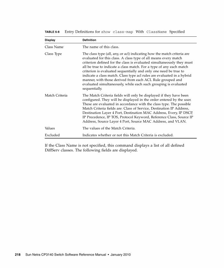
If the Class Name is not specified, this command displays a list of all definedDiffServ classes. The following fields are displayed.
TABLE 6-8 Entry Definitions for show class-map With ClassName Specified
Display Definition
Class Name The name of this class.
Class Type The class type (all, any, or acl) indicating how the match criteria areevaluated for this class. A class type of all means every matchcriterion defined for the class is evaluated simultaneously they mustall be true to indicate a class match. For a type of any each matchcriterion is evaluated sequentially and only one need be true toindicate a class match. Class type acl rules are evaluated in a hybridmanner, with those derived from each ACL Rule grouped andevaluated simultaneously, while each such grouping is evaluatedsequentially.
Match Criteria The Match Criteria fields will only be displayed if they have beenconfigured. They will be displayed in the order entered by the user.These are evaluated in accordance with the class type. The possibleMatch Criteria fields are: Class of Service, Destination IP Address,Destination Layer 4 Port, Destination MAC Address, Every, IP DSCP,IP Precedence, IP TOS, Protocol Keyword, Reference Class, Source IPAddress, Source Layer 4 Port, Source MAC Address, and VLAN.
Values The values of the Match Criteria.
Excluded Indicates whether or not this Match Criteria is excluded.
218 Sun Netra CP3140 Switch Software Reference Manual • January 2010
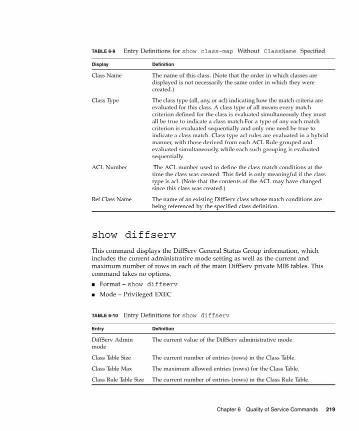
show diffserv
This command displays the DiffServ General Status Group information, whichincludes the current administrative mode setting as well as the current andmaximum number of rows in each of the main DiffServ private MIB tables. Thiscommand takes no options.
■ Format – show diffserv
■ Mode – Privileged EXEC
TABLE 6-9 Entry Definitions for show class-map Without ClassName Specified
Display Definition
Class Name The name of this class. (Note that the order in which classes aredisplayed is not necessarily the same order in which they werecreated.)
Class Type The class type (all, any, or acl) indicating how the match criteria areevaluated for this class. A class type of all means every matchcriterion defined for the class is evaluated simultaneously they mustall be true to indicate a class match.For a type of any each matchcriterion is evaluated sequentially and only one need be true toindicate a class match. Class type acl rules are evaluated in a hybridmanner, with those derived from each ACL Rule grouped andevaluated simultaneously, while each such grouping is evaluatedsequentially.
ACL Number The ACL number used to define the class match conditions at thetime the class was created. This field is only meaningful if the classtype is acl. (Note that the contents of the ACL may have changedsince this class was created.)
Ref Class Name The name of an existing DiffServ class whose match conditions arebeing referenced by the specified class definition.
TABLE 6-10 Entry Definitions for show diffserv
Entry Definition
DiffServ Adminmode
The current value of the DiffServ administrative mode.
Class Table Size The current number of entries (rows) in the Class Table.
Class Table Max The maximum allowed entries (rows) for the Class Table.
Class Rule Table Size The current number of entries (rows) in the Class Rule Table.
Chapter 6 Quality of Service Commands 219
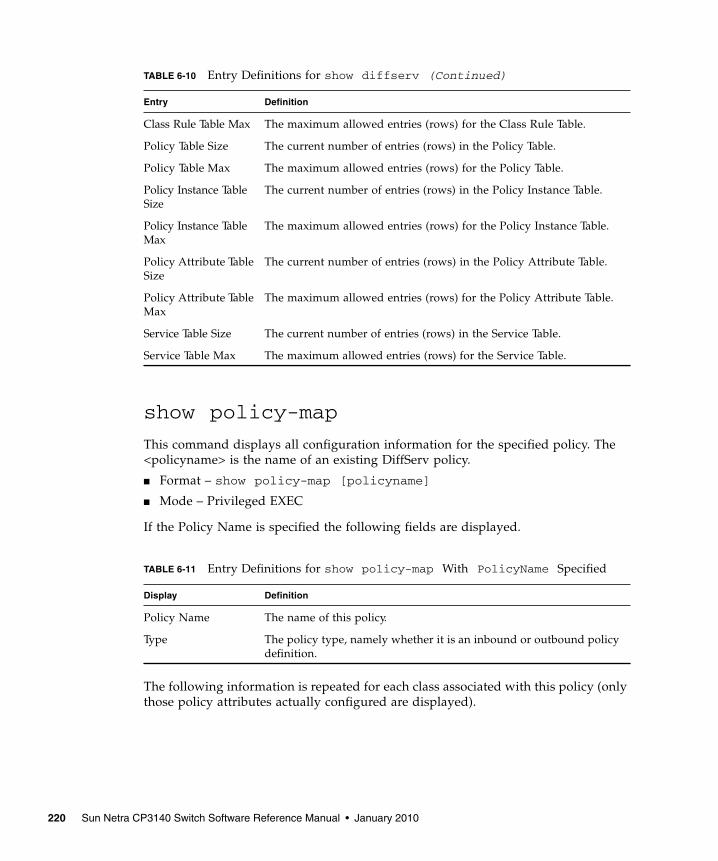
show policy-map
This command displays all configuration information for the specified policy. The<policyname> is the name of an existing DiffServ policy.
■ Format – show policy-map [policyname]
■ Mode – Privileged EXEC
If the Policy Name is specified the following fields are displayed.
The following information is repeated for each class associated with this policy (onlythose policy attributes actually configured are displayed).
Class Rule Table Max The maximum allowed entries (rows) for the Class Rule Table.
Policy Table Size The current number of entries (rows) in the Policy Table.
Policy Table Max The maximum allowed entries (rows) for the Policy Table.
Policy Instance TableSize
The current number of entries (rows) in the Policy Instance Table.
Policy Instance TableMax
The maximum allowed entries (rows) for the Policy Instance Table.
Policy Attribute TableSize
The current number of entries (rows) in the Policy Attribute Table.
Policy Attribute TableMax
The maximum allowed entries (rows) for the Policy Attribute Table.
Service Table Size The current number of entries (rows) in the Service Table.
Service Table Max The maximum allowed entries (rows) for the Service Table.
TABLE 6-11 Entry Definitions for show policy-map With PolicyName Specified
Display Definition
Policy Name The name of this policy.
Type The policy type, namely whether it is an inbound or outbound policydefinition.
TABLE 6-10 Entry Definitions for show diffserv (Continued)
Entry Definition
220 Sun Netra CP3140 Switch Software Reference Manual • January 2010
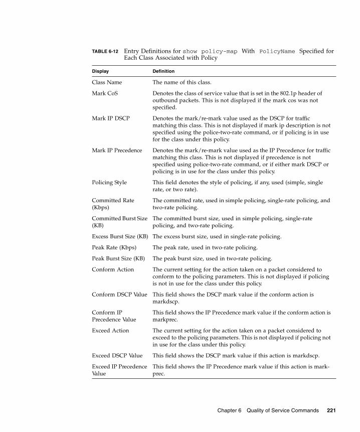
TABLE 6-12 Entry Definitions for show policy-map With PolicyName Specified forEach Class Associated with Policy
Display Definition
Class Name The name of this class.
Mark CoS Denotes the class of service value that is set in the 802.1p header ofoutbound packets. This is not displayed if the mark cos was notspecified.
Mark IP DSCP Denotes the mark/re-mark value used as the DSCP for trafficmatching this class. This is not displayed if mark ip description is notspecified using the police-two-rate command, or if policing is in usefor the class under this policy.
Mark IP Precedence Denotes the mark/re-mark value used as the IP Precedence for trafficmatching this class. This is not displayed if precedence is notspecified using police-two-rate command, or if either mark DSCP orpolicing is in use for the class under this policy.
Policing Style This field denotes the style of policing, if any, used (simple, singlerate, or two rate).
Committed Rate(Kbps)
The committed rate, used in simple policing, single-rate policing, andtwo-rate policing.
Committed Burst Size(KB)
The committed burst size, used in simple policing, single-ratepolicing, and two-rate policing.
Excess Burst Size (KB) The excess burst size, used in single-rate policing.
Peak Rate (Kbps) The peak rate, used in two-rate policing.
Peak Burst Size (KB) The peak burst size, used in two-rate policing.
Conform Action The current setting for the action taken on a packet considered toconform to the policing parameters. This is not displayed if policingis not in use for the class under this policy.
Conform DSCP Value This field shows the DSCP mark value if the conform action ismarkdscp.
Conform IPPrecedence Value
This field shows the IP Precedence mark value if the conform action ismarkprec.
Exceed Action The current setting for the action taken on a packet considered toexceed to the policing parameters. This is not displayed if policing notin use for the class under this policy.
Exceed DSCP Value This field shows the DSCP mark value if this action is markdscp.
Exceed IP PrecedenceValue
This field shows the IP Precedence mark value if this action is mark-prec.
Chapter 6 Quality of Service Commands 221

If the Policy Name is not specified this command displays a list of all definedDiffServ policies. The following fields are displayed.
Non-Conform Action The current setting for the action taken on a packet considered to notconform to the policing parameters. This is not displayed if policingnot in use for the class under this policy.
Non-Conform DSCPValue
The DSCP mark value if this action is markdscp.
Non-Conform IPPrecedence Value
The IP Precedence mark value if this action is markprec.
Bandwidth The minimum amount of bandwidth reserved in either percent orkilobits-per-second.
Expedite Burst Size(KBytes)
The maximum guaranteed amount of bandwidth reserved in eitherpercent or kilobits-per-second format.
Shaping Average This field is displayed if average shaping is in use. Indicates whetheraverage or peak rate shaping is in use, along with the parameters usedto form the traffic shaping criteria, such as CIR and PIR. This is notdisplayed if shaping is not configured for the class under this policy.
Shape CommittedRate (Kbps)
This field is displayed if average or peak rate shaping is in use. Itdisplays the shaping committed rate in kilobits-per-second.
Shape Peak Rate(Kbps)
This field is displayed if peak rate shaping is in use. It displays theshaping peak rate in kilobits-per-second.
Random DropMinimum Threshold
The RED minimum threshold.This is not displayed if the queue depthmanagement scheme is not RED.
Random DropMaximum Threshold
The RED maximum threshold.This is not displayed if the queue depthmanagement scheme is not RED.
Random DropMaximum DropProbability
The RED maximum drop probability.This is not displayed if thequeue depth management scheme is not RED.
Random DropSampling Rate
The RED sampling rate.This is not displayed if the queue depthmanagement scheme is not RED.
Random Drop DecayExponent
The RED decay exponent.This is not displayed if the queue depthmanagement scheme is not RED.
TABLE 6-12 Entry Definitions for show policy-map With PolicyName Specified forEach Class Associated with Policy (Continued)
Display Definition
222 Sun Netra CP3140 Switch Software Reference Manual • January 2010
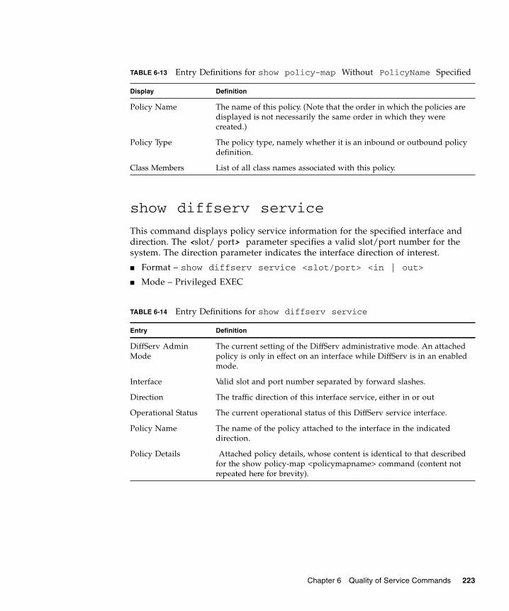
show diffserv service
This command displays policy service information for the specified interface anddirection. The <slot/ port> parameter specifies a valid slot/port number for thesystem. The direction parameter indicates the interface direction of interest.
■ Format – show diffserv service <slot/port> <in | out>
■ Mode – Privileged EXEC
TABLE 6-13 Entry Definitions for show policy-map Without PolicyName Specified
Display Definition
Policy Name The name of this policy. (Note that the order in which the policies aredisplayed is not necessarily the same order in which they werecreated.)
Policy Type The policy type, namely whether it is an inbound or outbound policydefinition.
Class Members List of all class names associated with this policy.
TABLE 6-14 Entry Definitions for show diffserv service
Entry Definition
DiffServ AdminMode
The current setting of the DiffServ administrative mode. An attachedpolicy is only in effect on an interface while DiffServ is in an enabledmode.
Interface Valid slot and port number separated by forward slashes.
Direction The traffic direction of this interface service, either in or out
Operational Status The current operational status of this DiffServ service interface.
Policy Name The name of the policy attached to the interface in the indicateddirection.
Policy Details Attached policy details, whose content is identical to that describedfor the show policy-map <policymapname> command (content notrepeated here for brevity).
Chapter 6 Quality of Service Commands 223

show diffserv service brief
This command displays all interfaces in the system to which a DiffServ policy hasbeen attached. The direction parameter is optional; if specified, only services in theindicated direction are shown, otherwise service information is shown for bothdirections, where applicable.
■ Format – show diffserv service brief [in | out]
■ Mode – Privileged EXEC
The following information is repeated for interface and direction (only thoseinterfaces configured with an attached policy are shown).
show policy-map interface
This command displays policy-oriented statistics information for the specifiedinterface and direction. The <slot/port> parameter specifies a valid interface for thesystem. The direction parameter indicates the interface direction of interest.
Note – This command is only allowed while the DiffServ administrative mode isenabled.
■ Format – show policy-map interface <slot/port> <in | out>
TABLE 6-15 Entry Definitions for show diffserv service brief
Entry Definition
DiffServ Mode The current setting of the DiffServ administrative mode. An attachedpolicy is only active on an interface while DiffServ is in an enabledmode.
TABLE 6-16 Entry Definitions for show diffserv service brief For Interface andDirection
Entry Definition
Interface Valid slot and port number separated by forward slashes.
Direction The traffic direction of this interface service, either in or out
OperStatus The current operational status of this DiffServ service interface.
Policy Name The name of the policy attached to the interface in the indicateddirection.
224 Sun Netra CP3140 Switch Software Reference Manual • January 2010
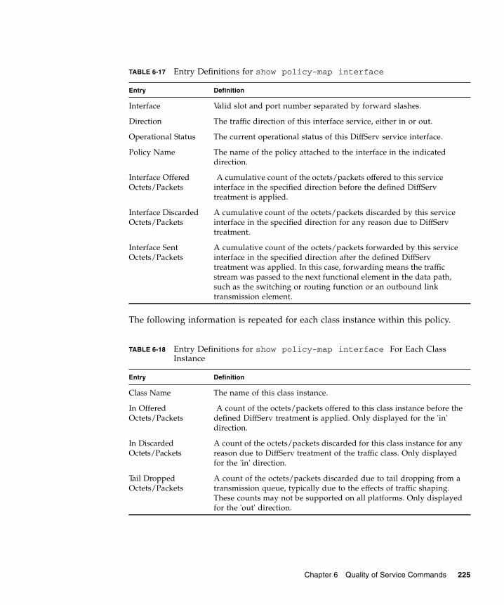
The following information is repeated for each class instance within this policy.
TABLE 6-17 Entry Definitions for show policy-map interface
Entry Definition
Interface Valid slot and port number separated by forward slashes.
Direction The traffic direction of this interface service, either in or out.
Operational Status The current operational status of this DiffServ service interface.
Policy Name The name of the policy attached to the interface in the indicateddirection.
Interface OfferedOctets/Packets
A cumulative count of the octets/packets offered to this serviceinterface in the specified direction before the defined DiffServtreatment is applied.
Interface DiscardedOctets/Packets
A cumulative count of the octets/packets discarded by this serviceinterface in the specified direction for any reason due to DiffServtreatment.
Interface SentOctets/Packets
A cumulative count of the octets/packets forwarded by this serviceinterface in the specified direction after the defined DiffServtreatment was applied. In this case, forwarding means the trafficstream was passed to the next functional element in the data path,such as the switching or routing function or an outbound linktransmission element.
TABLE 6-18 Entry Definitions for show policy-map interface For Each ClassInstance
Entry Definition
Class Name The name of this class instance.
In OfferedOctets/Packets
A count of the octets/packets offered to this class instance before thedefined DiffServ treatment is applied. Only displayed for the 'in'direction.
In DiscardedOctets/Packets
A count of the octets/packets discarded for this class instance for anyreason due to DiffServ treatment of the traffic class. Only displayedfor the 'in' direction.
Tail DroppedOctets/Packets
A count of the octets/packets discarded due to tail dropping from atransmission queue, typically due to the effects of traffic shaping.These counts may not be supported on all platforms. Only displayedfor the 'out' direction.
Chapter 6 Quality of Service Commands 225
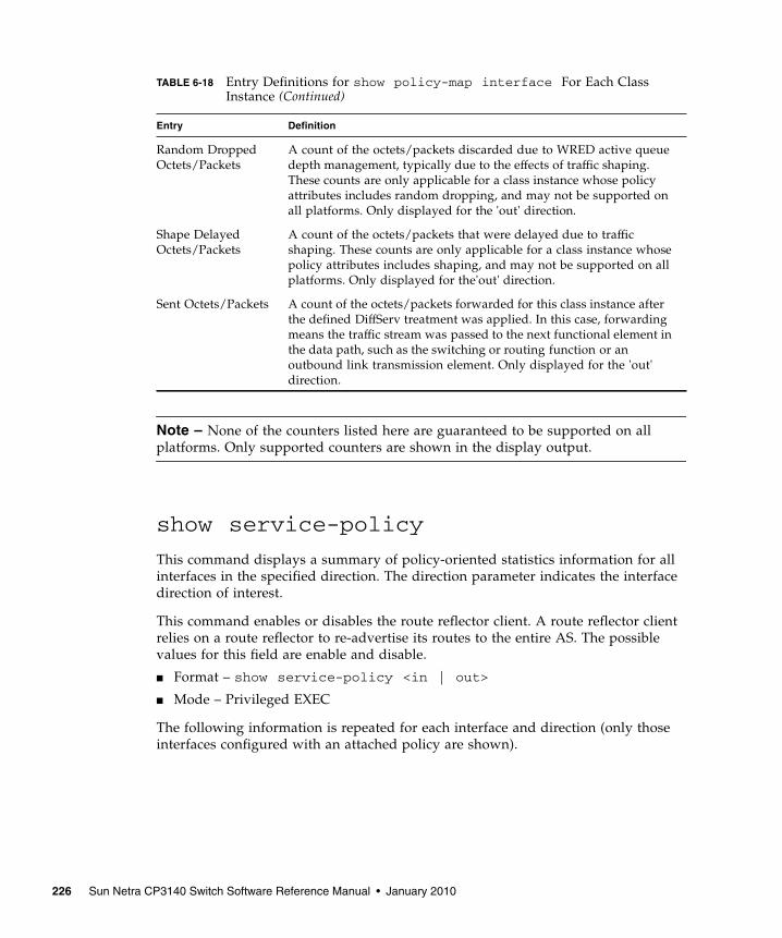
Note – None of the counters listed here are guaranteed to be supported on allplatforms. Only supported counters are shown in the display output.
show service-policy
This command displays a summary of policy-oriented statistics information for allinterfaces in the specified direction. The direction parameter indicates the interfacedirection of interest.
This command enables or disables the route reflector client. A route reflector clientrelies on a route reflector to re-advertise its routes to the entire AS. The possiblevalues for this field are enable and disable.
■ Format – show service-policy <in | out>
■ Mode – Privileged EXEC
The following information is repeated for each interface and direction (only thoseinterfaces configured with an attached policy are shown).
Random DroppedOctets/Packets
A count of the octets/packets discarded due to WRED active queuedepth management, typically due to the effects of traffic shaping.These counts are only applicable for a class instance whose policyattributes includes random dropping, and may not be supported onall platforms. Only displayed for the 'out' direction.
Shape DelayedOctets/Packets
A count of the octets/packets that were delayed due to trafficshaping. These counts are only applicable for a class instance whosepolicy attributes includes shaping, and may not be supported on allplatforms. Only displayed for the'out' direction.
Sent Octets/Packets A count of the octets/packets forwarded for this class instance afterthe defined DiffServ treatment was applied. In this case, forwardingmeans the traffic stream was passed to the next functional element inthe data path, such as the switching or routing function or anoutbound link transmission element. Only displayed for the 'out'direction.
TABLE 6-18 Entry Definitions for show policy-map interface For Each ClassInstance (Continued)
Entry Definition
226 Sun Netra CP3140 Switch Software Reference Manual • January 2010
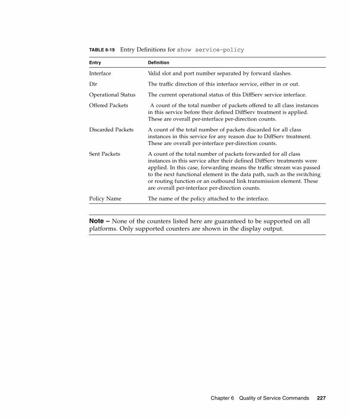
Note – None of the counters listed here are guaranteed to be supported on allplatforms. Only supported counters are shown in the display output.
TABLE 6-19 Entry Definitions for show service-policy
Entry Definition
Interface Valid slot and port number separated by forward slashes.
Dir The traffic direction of this interface service, either in or out.
Operational Status The current operational status of this DiffServ service interface.
Offered Packets A count of the total number of packets offered to all class instancesin this service before their defined DiffServ treatment is applied.These are overall per-interface per-direction counts.
Discarded Packets A count of the total number of packets discarded for all classinstances in this service for any reason due to DiffServ treatment.These are overall per-interface per-direction counts.
Sent Packets A count of the total number of packets forwarded for all classinstances in this service after their defined DiffServ treatments wereapplied. In this case, forwarding means the traffic stream was passedto the next functional element in the data path, such as the switchingor routing function or an outbound link transmission element. Theseare overall per-interface per-direction counts.
Policy Name The name of the policy attached to the interface.
Chapter 6 Quality of Service Commands 227

228 Sun Netra CP3140 Switch Software Reference Manual • January 2010

CHAPTER 7
Routing Commands
This chapter provides detailed explanations of the Routing commands.
Note – The commands in this appendix are not officially supported by SunMicrosystems. The information in this appendix is provided as a courtesy; use themat your own risk.
This chapter contains the following topics:
■ “Address Resolution Protocol Commands” on page 230
■ “IP Routing” on page 235
■ “Bootp/DHCP Relay Commands” on page 246
■ “Router Discovery Protocol Commands” on page 249
■ “Virtual LAN Routing Commands” on page 252
■ “Virtual Router Redundancy Protocol (VRRP) Commands” on page 254
■ “VRRP Tracking Commands” on page 260
■ “Open Shortest Path First (OSPF) Commands” on page 263
■ “Routing Information Protocol (RIP) Commands” on page 291
229

Address Resolution Protocol CommandsThis section provides a detailed explanation of the Address Resolution Protocol(ARP) commands. The commands are divided by functionality into the followingdifferent groups:
■ Show commands are used to display switch settings, statistics and otherinformation.
■ Configuration commands are used to configure features and options of theswitch. For every configuration command there is a show command that willdisplay the configuration setting.
■ Copy commands are used to transfer configuration and informational files to andfrom the switch.
arp
This command creates an ARP entry. The value for <ipaddress> is the IP address ofa device on a subnet attached to an existing routing interface. <macaddr> is aunicast MAC address for that device. The format is 6 two-digit hexadecimalnumbers that are separated by colons, for example 00:06:29:32:81:40.
■ Format – arp <ipaddress> <macaddr>
■ Mode – Global Config
no arp
This command deletes an ARP entry. The value for <arpentry> is the IP address ofthe interface. The value for <ipaddress> is the IP address of a device on a subnetattached to an existing routing interface. <macaddr> is a unicast MAC address forthat device.
■ Format – no arp <ipaddress> <macaddr>
■ Mode – Global Config
arp cachesize
This command configures the ARP cache size. The value for <cachesize> is aplatform specific integer value.
■ Format – arp cachesize <Platform specific integer value>
230 Sun Netra CP3140 Switch Software Reference Manual • January 2010

■ Mode – Global Config
no arp cachesize
This command configures the default ARP cache size.
■ Format – no arp cachesize
■ Mode – Global Config
arp dynamicrenew
This command enables ARP component to automatically renew ARP entries of typedynamic when they age out.
■ Format – arp dynamicrenew
■ Mode – Privileged Exec
no arp dynamicrenew
This command disables ARP component from automatically renewing ARP entriesof type dynamic when they age out.
■ Format – no arp dynamicrenew
■ Mode – Privileged Exec
arp purge
This command causes the specified IP address to be removed from the ARP cache.Only entries of type dynamic or gateway are affected by this command.
■ Format – arp purge <ipaddr>
■ Mode – Privileged EXEC
arp resptime
This command configures the ARP request response timeout.
The value for <seconds> is a valid positive integer, which represents the IP ARPentry response timeout time in seconds. The range for <seconds> is between 1-10seconds.
Chapter 7 Routing Commands 231
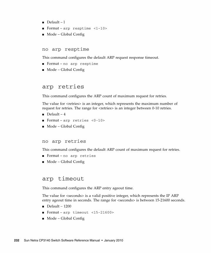
■ Default – l
■ Format – arp resptime <1-10>
■ Mode – Global Config
no arp resptime
This command configures the default ARP request response timeout.
■ Format – no arp resptime
■ Mode – Global Config
arp retries
This command configures the ARP count of maximum request for retries.
The value for <retries> is an integer, which represents the maximum number ofrequest for retries. The range for <retries> is an integer between 0-10 retries.
■ Default – 4
■ Format – arp retries <0-10>
■ Mode – Global Config
no arp retries
This command configures the default ARP count of maximum request for retries.
■ Format – no arp retries
■ Mode – Global Config
arp timeout
This command configures the ARP entry ageout time.
The value for <seconds> is a valid positive integer, which represents the IP ARPentry ageout time in seconds. The range for <seconds> is between 15-21600 seconds.
■ Default – 1200
■ Format – arp timeout <15-21600>
■ Mode – Global Config
232 Sun Netra CP3140 Switch Software Reference Manual • January 2010
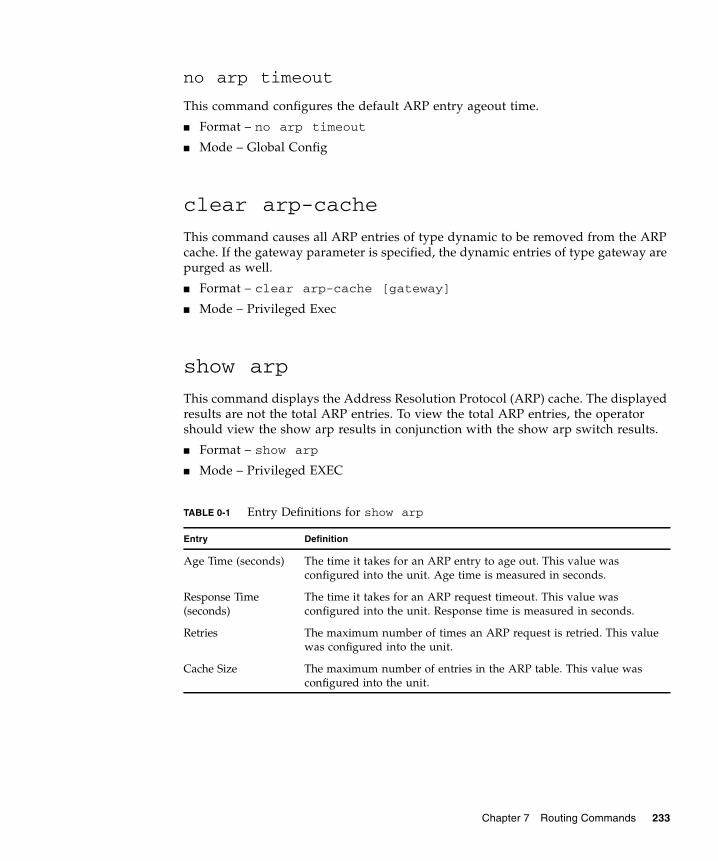
no arp timeout
This command configures the default ARP entry ageout time.
■ Format – no arp timeout
■ Mode – Global Config
clear arp-cache
This command causes all ARP entries of type dynamic to be removed from the ARPcache. If the gateway parameter is specified, the dynamic entries of type gateway arepurged as well.
■ Format – clear arp-cache [gateway]
■ Mode – Privileged Exec
show arp
This command displays the Address Resolution Protocol (ARP) cache. The displayedresults are not the total ARP entries. To view the total ARP entries, the operatorshould view the show arp results in conjunction with the show arp switch results.
■ Format – show arp
■ Mode – Privileged EXEC
TABLE 0-1 Entry Definitions for show arp
Entry Definition
Age Time (seconds) The time it takes for an ARP entry to age out. This value wasconfigured into the unit. Age time is measured in seconds.
Response Time(seconds)
The time it takes for an ARP request timeout. This value wasconfigured into the unit. Response time is measured in seconds.
Retries The maximum number of times an ARP request is retried. This valuewas configured into the unit.
Cache Size The maximum number of entries in the ARP table. This value wasconfigured into the unit.
Chapter 7 Routing Commands 233

The following are displayed for each ARP entry.
show arp brief
This command displays the brief Address Resolution Protocol (ARP) tableinformation.
■ Format – show arp brief
■ Mode – Privileged EXEC
Dynamic RenewMode
Displays whether the ARP component automatically attempts torenew dynamic ARP entries when they age out.
Total Entry CountCurrent / Peak
Field listing the total entries in the ARP table and the peak entrycount in the ARP table.
Static Entry CountCurrent / Max
Field listing the static entry count in the ARP table and maximumstatic entry count in the ARP table.
TABLE 0-2 Entry Definitions for show arp For Each ARP Entry
Display Definition
IP Address The IP address of a device on a subnet attached to an existing routinginterface.
MAC Address The hardware MAC address of that device.
Interface The routing slot/port associated with the device ARP entry.
Type The type that was configured into the unit. The possible values areLocal, Gateway, Dynamic and Static.
Age This field displays the current age of the ARP entry since last refresh(in hh:mm:ss format
TABLE 0-1 Entry Definitions for show arp
Entry Definition
234 Sun Netra CP3140 Switch Software Reference Manual • January 2010
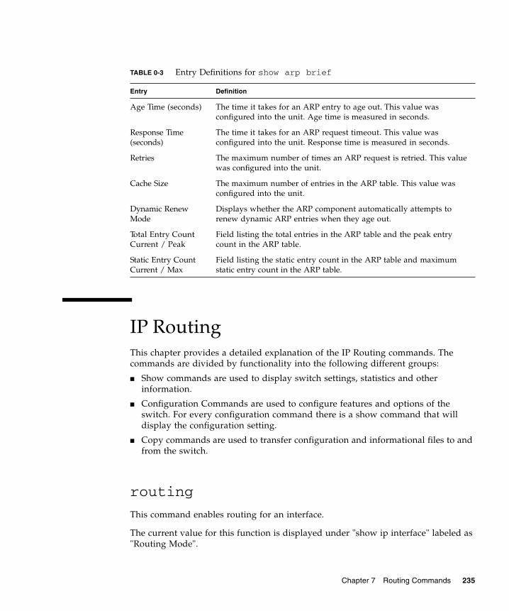
IP RoutingThis chapter provides a detailed explanation of the IP Routing commands. Thecommands are divided by functionality into the following different groups:
■ Show commands are used to display switch settings, statistics and otherinformation.
■ Configuration Commands are used to configure features and options of theswitch. For every configuration command there is a show command that willdisplay the configuration setting.
■ Copy commands are used to transfer configuration and informational files to andfrom the switch.
routing
This command enables routing for an interface.
The current value for this function is displayed under "show ip interface" labeled as"Routing Mode".
TABLE 0-3 Entry Definitions for show arp brief
Entry Definition
Age Time (seconds) The time it takes for an ARP entry to age out. This value wasconfigured into the unit. Age time is measured in seconds.
Response Time(seconds)
The time it takes for an ARP request timeout. This value wasconfigured into the unit. Response time is measured in seconds.
Retries The maximum number of times an ARP request is retried. This valuewas configured into the unit.
Cache Size The maximum number of entries in the ARP table. This value wasconfigured into the unit.
Dynamic RenewMode
Displays whether the ARP component automatically attempts torenew dynamic ARP entries when they age out.
Total Entry CountCurrent / Peak
Field listing the total entries in the ARP table and the peak entrycount in the ARP table.
Static Entry CountCurrent / Max
Field listing the static entry count in the ARP table and maximumstatic entry count in the ARP table.
Chapter 7 Routing Commands 235
■ Default – disabled
■ Format – routing
■ Mode – Interface Config
no routing
This command disables routing for an interface.
The current value for this function is displayed under "show ip interface" labeled as"Routing Mode".
■ Format – no routing
■ Mode – Interface Config
ip routing
This command enables the IP Router Admin Mode for the master switch.
■ Format – ip routing
■ Mode – Global Config
no ip routing
This command disables the IP Router Admin Mode for the master switch.
■ Format – no ip routing
■ Mode – Global Config
ip address
This command configures an IP address on an interface.
The value for <ipaddr> is the IP Address of the interface.
The value for <subnetmask> is a 4-digit dotted-decimal number which representsthe Subnet Mask of the interface. This changes the label "IP address" in "show ipinterface."
■ Format – ip address <ipaddr> <subnetmask>
■ Mode – Interface Config
236 Sun Netra CP3140 Switch Software Reference Manual • January 2010
no ip address
This command deletes an IP address from an interface. The value for <ipaddr> is theIP Address of the interface.
The value for <subnetmask> is a 4-digit dotted-decimal number which representsthe Subnet Mask of the interface.
■ Format – no ip address <ipaddr> <subnetmask>
■ Mode – Interface Config
ip route
This command configures a static route. The <ip_addr> is a valid ip address. The<subnet_mask> is a valid subnet mask. The <nextHopRtr> is a valid IP address ofthe next hop router. The <preference> is an integer value from 1 to 255.
■ Default – preference - 1
■ Format – ip route <ip_addr> <subnet_mask> <nextHopRtr>[<preference>]
■ Mode – Global Config
no ip route
This command deletes all next hops to a destination static route. If the optional<nextHopRtr> parameter is designated, the next hop is deleted and if the optionalpreference value is designated, the preference value of the static route is reset to itsdefault,
■ Format – no ip route <ip_addr> <subnet_mask> [{<nextHopRtr> |<preference>}]
■ Mode – Global Config
ip route default
This command configures the default route. The value for <nextHopRtr> is a validIP address of the next hop router. The <preference> is an integer value from 1 to 255
■ Default – preference - 1
■ Format – ip route default <nextHopRtr> [<preference>]
■ Mode – Global Config
Chapter 7 Routing Commands 237

no ip route default
This command deletes all configured default routes. If the optional <nextHopRtr>parameter is designated, the specific next hop is deleted from the configured defaultroute and if the optional preference value is designated, the preference of theconfigured default route is reset to its default.
■ Format – no ip route default [{<nextHopRtr> | <preference>}]
■ Mode – Global Config
ip route distance
This command sets the default distance for static routes. Lower route preferencevalues are preferred when determining the best route. The "ip route" and "ip routedefault" commands allow you to optionally set the distance of an individual staticroute. The default distance is used when no distance is specified in these commands.Changing the default distance does not update the distance of existing static routes,even if they were assigned the original default distance. The new default distancewill only be applied to static routes created after invoking the "ip route distance"command.
238 Sun Netra CP3140 Switch Software Reference Manual • January 2010

■ Default – 1
■ Format – ip route distance <1-255>
■ Mode – Global Config
no ip route distance
This command sets the default static route preference value in the router. Lowerroute preference values are preferred when determining the best route.
■ Format – no ip route distance
■ Mode – Global Config
ip forwarding
This command enables forwarding of IP frames.
■ Default – enabled
■ Format – ip forwarding
■ Mode – Global Config
no ip forwarding
This command disables forwarding of IP frames.
■ Format – no ip forwarding
■ Mode – Global Config
ip netdirbcast
This command enables the forwarding of network-directed broadcasts. Whenenabled, network directed broadcasts are forwarded. When disabled they aredropped.
■ Default – disabled
■ Format – ip netdirbcast
■ Mode – Interface Config
Chapter 7 Routing Commands 239
no ip netdirbcast
This command disables the forwarding of network-directed broadcasts. Whendisabled, network directed broadcasts are dropped.
■ Format – no ip netdirbcast
■ Mode – Interface Config
ip mtu
This command sets the maximum transmission unit (MTU) size of IP packets sent ona specific routing interface.
■ Default – 1500 bytes
■ Format – ip mtu <68 - 9194>
■ Mode – Interface Config
no ip mtu
This command sets the maximum transmission unit (MTU) size to the default value.
■ Format – no ip mtu
■ Mode – Interface Config
show ip brief
This command displays all the summary information of the IP. This command takesno options.
■ Format – show ip brief
■ Mode – Privileged EXEC and User EXEC
TABLE 0-4 Entry Definitions for show ip brief
Entry Definition
Default Time to Live The computed TTL (Time to Live) of forwarding a packet from thelocal router to the final destination.
240 Sun Netra CP3140 Switch Software Reference Manual • January 2010

show ip interface
This command displays all pertinent information about the IP interface.
■ Format – show ip interface <slot/port>
■ Mode – Privileged EXEC and User EXEC
Router ID A 32 bit integer in dotted decimal format identifying the router, aboutwhich information is displayed. This is a configured value.
Routing Mode Shows whether the routing mode is enabled or disabled.
IP Forwarding Mode Shows whether forwarding of IP frames is enabled or disabled. Thisis a configured value.
TABLE 0-5 Entry Definitions for show ip interface
Entry Definition
IP Address An IP address representing the subnet configuration of the routerinterface. This value was configured into the unit.
Subnet Mask A mask of the network and host portion of the IP address for therouter interface. This value was configured into the unit.
Routing Mode The administrative mode of router interface participation. Thepossible values are enable or disable. This value was configured intothe unit.
Administrative Mode The administrative mode of the specified interface. The possiblevalues of this field are enable or disable. This value was configuredinto the unit.
Forward Net DirectedBroadcasts
Displays whether forwarding of network-directed broadcasts isenabled or disabled. This value was configured into the unit.
Active State Displays whether the interface is active or inactive. An interface isconsidered active if its link is up and it is in forwarding state.
Link Speed Data Rate An integer representing the physical link data rate of the specifiedinterface. This is measured in Megabits per second (Mbps).
MAC Address The burned in physical address of the specified interface. The formatis 6 two-digit hexadecimal numbers that are separated by colons.
Encapsulation Type The encapsulation type for the specified interface. The types are:Ethernet or SNAP.
TABLE 0-4 Entry Definitions for show ip brief
Entry Definition
Chapter 7 Routing Commands 241
show ip interface brief
This command displays summary information about IP configuration settings for allports in the router. This command takes no options.
■ Format – show ip interface brief
■ Mode – Privileged EXEC and User EXEC
show ip route
This command displays the entire route table. This commands takes no options.
■ Format – show ip route
■ Mode – Privileged EXEC
TABLE 0-6 Entry Definitions for show ip interface brief
Entry Definition
Slot/Port Valid slot and port number separated by forward slashes.
IP Address The IP address of the routing interface in 32-bit dotted decimalformat.
IP Mask The IP mask of the routing interface in 32-bit dotted decimal format.
Netdir Bcast Indicates if IP forwards net-directed broadcasts on this interface.Possible values are Enable or Disable.
MultiCast Fwd Indicates the multicast forwarding administrative mode on theinterface. Possible values are Enable or Disable.
In Access Mode Indicates the inbound access list checking administrative mode onthis interface. Possible values are Enable or Disable.
Out Access Mode Indicates the outbound access list checking administrative mode onthis interface. Possible values are Enable or Disable.
TABLE 0-7 Entry Definitions for show ip route
Entry Definition
Network Address An IP address identifying the network on the specified interface.
242 Sun Netra CP3140 Switch Software Reference Manual • January 2010

For each Next Hop, the following is displayed.
show ip route bestroutes
This command causes the entire route table to be displayed. This commands takesno options.
■ Format – show ip route bestroutes
■ Mode – Privileged EXEC
For each Next Hop, the following is displayed.
Subnet Mask A mask of the network and host portion of the IP address for therouter interface.
Protocol Tells which protocol added the specified route. The possibilities are:local, static, OSPF or RIP.
Total Number ofRoutes
The total number of routes.
TABLE 0-8 Entry Definitions for show ip route For Each Next Hop
Display Definition
Next Hop Intf The outgoing router interface to use when forwarding traffic to thenext destination.
Next Hop IP Address The outgoing router IP address to use when forwarding traffic to thenext router (if any) in the path toward the destination.
TABLE 0-9 Entry Definitions for show ip route bestroutes
Entry Definition
Network Address An IP route prefix for the destination.
Subnet Mask A mask of the network and host portion of the IP address for thespecified interface.
Protocol Tells which protocol added the specified route. The possibilities are:local, static, OSPF or RIP.
Total Number ofRoutes
The total number of routes in the route table.
TABLE 0-7 Entry Definitions for show ip route
Entry Definition
Chapter 7 Routing Commands 243

show ip route entry
This command displays the entire route table.
■ Format – show ip route entry
■ Mode – Privileged EXEC
For each Next Hop, the following is displayed.
TABLE 0-10 Entry Definitions for show ip route bestroutes For Each Next Hop
Display Definition
Next Hop Intf The outgoing router interface to use when forwarding traffic to thenext destination.
Next Hop IP Address The outgoing router IP address to use when forwarding traffic to thenext router (if any) in the path toward the destination. The next routerwill always be one of the adjacent neighbors or the IP address of thelocal interface for a directly attached network.
TABLE 0-11 Entry Definitions for show ip route entry
Entry Definition
Network Address A valid network address identifying the network on the specifiedinterface.
Subnet Mask A mask of the network and host portion of the IP address for theattached network.
Protocol Tells which protocol added the specified route. The possibilities are:local, static, OSPF or RIP.
TABLE 0-12 Entry Definitions for show ip route entry For Each Next Hop
Display Definition
Next Hop Interface The outgoing router interface to use when forwarding traffic to thenext destination.
Next Hop IP Address The outgoing router IP address to use when forwarding traffic to thenext router (if any) in the path toward the destination.
Preference The metric value that is used for this route entry.
244 Sun Netra CP3140 Switch Software Reference Manual • January 2010
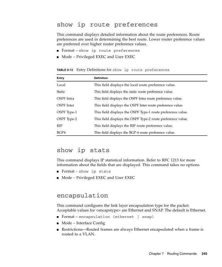
show ip route preferences
This command displays detailed information about the route preferences. Routepreferences are used in determining the best route. Lower router preference valuesare preferred over higher router preference values.
■ Format – show ip route preferences
■ Mode – Privileged EXEC and User EXEC
show ip stats
This command displays IP statistical information. Refer to RFC 1213 for moreinformation about the fields that are displayed. This command takes no options.
■ Format – show ip stats
■ Mode – Privileged EXEC and User EXEC
encapsulation
This command configures the link layer encapsulation type for the packet.Acceptable values for <encapstype> are Ethernet and SNAP. The default is Ethernet.
■ Format – encapsulation {ethernet | snap}
■ Mode – Interface Config
■ Restrictions—Routed frames are always Ethernet encapsulated when a frame isrouted to a VLAN.
TABLE 0-13 Entry Definitions for show ip route preferences
Entry Definition
Local This field displays the local route preference value.
Static This field displays the static route preference value.
OSPF Intra This field displays the OSPF Intra route preference value.
OSPF Inter This field displays the OSPF Inter route preference value.
OSPF Type-1 This field displays the OSPF Type-1 route preference value.
OSPF Type-2 This field displays the OSPF Type-2 route preference value.
RIP This field displays the RIP route preference value.
BGP4 This field displays the BGP-4 route preference value.
Chapter 7 Routing Commands 245

Bootp/DHCP Relay CommandsThis chapter provides a detailed explanation of the BootP/DHCP Relay commands.The commands are divided by functionality into the following different groups:
■ Show commands are used to display switch settings, statistics and otherinformation.
■ Configuration Commands are used to configure features and options of theswitch. For every configuration command there is a show command that willdisplay the configuration setting.
■ Copy commands are used to transfer configuration and informational files to andfrom the switch.
bootpdhcprelay cidoptmode
This command enables the circuit ID option mode for BootP/DHCP Relay on thesystem.
■ Default – disabled
■ Format – bootpdhcprelay cidoptmode
■ Mode – Global Config
no bootpdhcprelay cidoptmode
This command disables the circuit ID option mode for BootP/DHCP Relay on thesystem.
■ Format – no bootpdhcprelay cidoptmode
■ Mode – Global Config
bootpdhcprelay enable
This command enables the forwarding of relay requests for BootP/DHCP Relay onthe system.
■ Default – disabled
■ Format – bootpdhcprelay enable
■ Mode – Global Config
246 Sun Netra CP3140 Switch Software Reference Manual • January 2010

no bootpdhcprelay enable
This command disables the forwarding of relay requests for BootP/DHCP Relay onthe system.
■ Format – no bootpdhcprelay enable
■ Mode – Global Config
bootpdhcprelay maxhopcount
This command configures the maximum allowable relay agent hops forBootP/DHCP Relay on the system. The <hops> parameter has a range of 1 to 16.
■ Default – 4
■ Format – bootpdhcprelay maxhopcount <1-16>
■ Mode – Global Config
no bootpdhcprelay maxhopcount
This command configures the default maximum allowable relay agent hops forBootP/DHCP Relay on the system.
■ Format – no bootpdhcprelay maxhopcount
■ Mode – Global Config
bootpdhcprelay minwaittime
This command configures the minimum wait time in seconds for BootP/DHCPRelay on the system. When the BOOTP relay agent receives a BOOTREQUESTmessage, it MAY use the seconds-since-client-began-booting field of the request as afactor in deciding whether to relay the request or not. The parameter has a range of0 to 100 seconds.
■ Default – 0
■ Format – bootpdhcprelay minwaittime <0-100>
■ Mode – Global Config
no bootpdhcprelay minwaittime
This command configures the default minimum wait time in seconds forBootP/DHCP Relay on the system.
Chapter 7 Routing Commands 247

■ Format – no bootpdhcprelay minwaittime
■ Mode – Global Config
bootpdhcprelay serverip
This command configures the server IP Address for BootP/DHCP Relay on thesystem. The <ipaddr>
parameter is an IP address in a 4-digit dotted decimal format.
■ Default – 0.0.0.0
■ Format – bootpdhcprelay serverip <ipaddr>
■ Mode – Global Config
no bootpdhcprelay serverip
This command configures the default server IP Address for BootP/DHCP Relay onthe system.
■ Format – no bootpdhcprelay serverip
■ Mode – Global Config
show bootpdhcprelay
This command displays the BootP/DHCP Relay information.
■ Format – show bootpdhcprelay
■ Mode – Privileged EXEC and User EXEC
TABLE 0-14 Entry Definitions for show bootpdhcprelay
Entry Definition
Maximum HopCount
The maximum allowable relay agent hops.
Minimum Wait Time(Seconds)
The minimum wait time.
Admin Mode Represents whether relaying of requests is enabled or disabled.
Server IP Address The IP Address for the BootP/DHCP Relay server.
Circuit Id OptionMode
The DHCP circuit Id option which may be enabled or disabled.
248 Sun Netra CP3140 Switch Software Reference Manual • January 2010
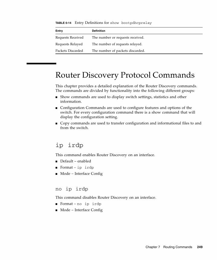
Router Discovery Protocol CommandsThis chapter provides a detailed explanation of the Router Discovery commands.The commands are divided by functionality into the following different groups:
■ Show commands are used to display switch settings, statistics and otherinformation.
■ Configuration Commands are used to configure features and options of theswitch. For every configuration command there is a show command that willdisplay the configuration setting.
■ Copy commands are used to transfer configuration and informational files to andfrom the switch.
ip irdp
This command enables Router Discovery on an interface.
■ Default – enabled
■ Format – ip irdp
■ Mode – Interface Config
no ip irdp
This command disables Router Discovery on an interface.
■ Format – no ip irdp
■ Mode – Interface Config
Requests Received The number or requests received.
Requests Relayed The number of requests relayed.
Packets Discarded The number of packets discarded.
TABLE 0-14 Entry Definitions for show bootpdhcprelay
Entry Definition
Chapter 7 Routing Commands 249
ip irdp address
This command configures the address to be used to advertise the router for theinterface. The valid values for ipaddr are 224.0.0.1 and 255.255.255.255.
■ Default – 224.0.0.1
■ Format – ip irdp address <ipaddr>
■ Mode – Interface Config
no ip irdp address
This command configures the default address to be used to advertise the router forthe interface.
■ Format – no ip irdp address
■ Mode – Interface Config
ip irdp holdtime
This command configures the value, in seconds, of the holdtime field of the routeradvertisement sent from this interface. The range is the maxadvertinterval to 9000seconds.
■ Default – 3 * maxinterval
■ Format – ip irdp holdtime <maxadvertinterval-9000>
■ Mode – Interface Config
no ip irdp holdtime
This command configures the default value, in seconds, of the holdtime field of therouter advertisement sent from this interface.
■ Format – no ip irdp holdtime
■ Mode – Interface Config
ip irdp maxadvertinterval
This command configures the maximum time, in seconds, allowed between sendingrouter advertisements from the interface. The range for maxadvertinterval is 4 to1800 seconds.
250 Sun Netra CP3140 Switch Software Reference Manual • January 2010
■ Default – 600
■ Format – ip irdp maxadvertinterval <4-1800>
■ Mode – Interface Config
no ip irdp maxadvertinterval
This command configures the default maximum time, in seconds.
■ Format – no ip irdp maxadvertinterval
■ Mode – Interface Config
ip irdp minadvertinterval
This command configures the minimum time, in seconds, allowed between sendingrouter advertisements from the interface. The range for minadvertinterval is 3 to thevalue of maxadvertinterval.
■ Default – 0.75 * maxadvertinterval
■ Format – ip irdp minadvertinterval <3-maxadvertinterval>
■ Mode – Interface Config
no ip irdp minadvertinterval
This command configures the default minimum time, in seconds.
■ Format – no ip irdp minadvertinterval
■ Mode – Interface Config
ip irdp preference
This command configures the preferability of the address as a default router address,relative to other router addresses on the same subnet. The range is -2147483648 to -1to 0 to 1 to 2147483647.
■ Default – 0
■ Format – ip irdp preference <-2147483648-2147483647>
■ Mode – Interface Config
Chapter 7 Routing Commands 251

no ip irdp preference
This command configures the default preferability of the address as a default routeraddress, relative to other router addresses on the same subnet.
■ Format – no ip irdp preference
■ Mode – Interface Config
show ip irdp
This command displays the router discovery information for all interfaces, or aspecified interface.
■ Format – show ip irdp {<slot/port> | all}
■ Mode – Privileged EXEC and User EXEC
Virtual LAN Routing CommandsThis chapter provides a detailed explanation of the Virtual LAN Routing commands.The commands are divided by functionality into the following different groups:
■ Show commands are used to display switch settings, statistics and otherinformation.
TABLE 0-15 Entry Definitions for show ip irdp
DIsplay Definition
Ad Mode Displays the advertise mode which indicates whether routerdiscovery is enabled or disabled on this interface.
Max Int Displays the maximum advertise interval which is the maximum timeallowed between sending router advertisements from the interface inseconds.
Min Int Displays the minimum advertise interval which is the minimum timeallowed between sending router advertisements from the interface inseconds.
Adv Life Displays advertise lifetime which is the value of the lifetime field ofthe router advertisement sent from the interface in seconds.
Preferences Displays the preference of the address as a default router address,relative to other router addresses on the same subnet.
252 Sun Netra CP3140 Switch Software Reference Manual • January 2010

■ Configuration Commands are used to configure features and options of theswitch. For every configuration command there is a show command that willdisplay the configuration setting.
■ Copy commands are used to transfer configuration and informational files to andfrom the switch.
vlan routing
This command creates routing on a VLAN. The <vlanid> value has a range from 1 to4021.
■ Format – vlan routing <vlanid>
■ Mode – VLAN Database
no vlan routing
This command deletes routing on a VLAN. The <vlanid> value has a range from 1 to4021.
■ Format – no vlan routing <vlanid>
■ Mode – VLAN Database
show ip vlan
This command displays the VLAN routing information for all VLANs with routingenabled in the system.
■ Format – show ip vlan
■ Mode – Privileged EXEC and User EXEC
TABLE 0-16 Entry Definitions for show ip vlan
Display Definition
MAC Address usedby Routing VLANs
The MAC Address associated with the internal bridge-router interface(IBRI). The same MAC Address is used by all VLAN routinginterfaces. It will be displayed above the per-VLAN information.
VLAN ID The identifier of the VLAN.
Chapter 7 Routing Commands 253
Virtual Router Redundancy Protocol(VRRP) CommandsThis section provides a detailed explanation of the VRRP commands. The commandsare divided by functionality into the following different groups:
■ Show commands are used to display switch settings, statistics and otherinformation.
■ Configuration Commands are used to configure features and options of theswitch. For every configuration command there is a show command that willdisplay the configuration setting.
■ Copy commands are used to transfer configuration and informational files to andfrom the switch.
ip vrrp
This command sets the virtual router ID on an interface for Virtual routerconfiguration in the router. The parameter <vrID> is the virtual router ID which hasan integer value range from 1 to 255.
■ Default – none
■ Format – ip vrrp <vrID>
■ Mode – Interface Config
no ip vrrp
This command removes all VRRP configuration details of the virtual routerconfigured on a specific interface. The parameter <vrID> is the virtual router IDwhich has an integer value ranges from 1 to 255.
■ Format – no ip vrrp <vrID>
Logical Interface Indicates the logical slot/port associated with the VLAN routinginterface.
IP Address Displays the IP Address associated with this VLAN.
Subnet Mask Indicates the subnet mask that is associated with this VLAN.
TABLE 0-16 Entry Definitions for show ip vlan
Display Definition
254 Sun Netra CP3140 Switch Software Reference Manual • January 2010

■ Mode – Interface Config
ip vrrp
This command enables the administrative mode of VRRP in the router.
■ Default – enabled
■ Format – ip vrrp
■ Mode – Global Config
no ip vrrp
This command disables the default administrative mode of VRRP in the router.
■ Format – no ip vrrp
■ Mode – Global Config
ip vrrp mode
This command enables the virtual router configured on the specified interface.Enabling the status field starts a virtual router. The parameter <vrID> is the virtualrouter ID which has an integer value ranging from 1 to 255.
■ Default – disabled
■ Format – ip vrrp <vrID> mode
■ Mode – Interface Config
no ip vrrp mode
This command disables the virtual router configured on the specified interface.Disabling the status field stops a virtual router.
■ Format – no ip vrrp <vrID> mode
■ Mode – Interface Config
Chapter 7 Routing Commands 255
ip vrrp ip
This command sets the ipaddress value for a virtual router. The value for <ipaddr>is the IP Address which is to be configured on that interface for VRRP. Theparameter <vrID> is the virtual router ID which has an integer value range from 1 to255.
■ Default – none
■ Format – ip vrrp <vrID> ip <ipaddr>
■ Mode – Interface Config
ip vrrp authentication
This command sets the authorization details value for the virtual router configuredon a specified interface. The parameter {none | simple} specifies the authorizationtype for virtual router configured on the specified interface. The parameter [key] isoptional, it is only required when authorization type is simple text password. Theparameter <vrID> is the virtual router ID which has an integer value ranges from 1to 255.
■ Default – no authorization
■ Format – ip vrrp <vrID> authentication {none | simple <key>}
■ Mode – Interface Config
no ip vrrp authentication
This command sets the default authorization details value for the virtual routerconfigured on a specified interface.
■ Format – no ip vrrp <vrID> authentication
■ Mode – Interface Config
ip vrrp preempt
This command sets the preemption mode value for the virtual router configured ona specified interface. The parameter <vrID> is the virtual router ID which has aninteger value range from 1 to 255.
■ Default – enabled
■ Format – ip vrrp <vrID> preempt
■ Mode – Interface Config
256 Sun Netra CP3140 Switch Software Reference Manual • January 2010

no ip vrrp preempt
This command sets the default preemption mode value for the virtual routerconfigured on a specified interface.
■ Format – no ip vrrp <vrID> preempt
■ Mode – Interface Config
ip vrrp priority
This command sets the priority value for the virtual router configured on a specifiedinterface. The priority of the interface is a priority integer from 1 to 254. Theparameter <vrID> is the virtual router ID which has an integer value ranges from 1to 255.
■ Default – 100
■ Format – ip vrrp <vrID> priority <1-254>
■ Mode – Interface Config
no ip vrrp priority
This command sets the default priority value for the virtual router configured on aspecified interface.
■ Format – no ip vrrp <vrID> priority
■ Mode – Interface Config
ip vrrp timers advertise
This command sets the advertisement value for a virtual router. The value foradvinterval is time used for VRRP advertisement in seconds. The parameter <vrID>is the virtual router ID which has an integer value range from 1 to 255.
■ Default – 1
■ Format – ip vrrp <vrID> timers advertise <1-255>
■ Mode – Interface Config
no ip vrrp timers advertise
This command sets the default advertisement value for a virtual router.
■ Format – no ip vrrp <vrID> timers advertise
Chapter 7 Routing Commands 257
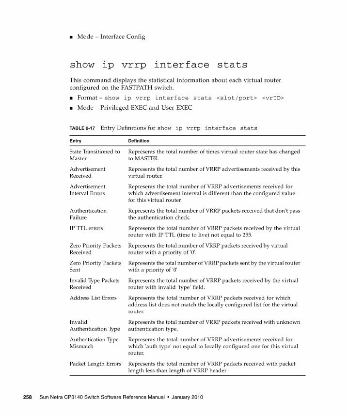
■ Mode – Interface Config
show ip vrrp interface stats
This command displays the statistical information about each virtual routerconfigured on the FASTPATH switch.
■ Format – show ip vrrp interface stats <slot/port> <vrID>
■ Mode – Privileged EXEC and User EXEC
TABLE 0-17 Entry Definitions for show ip vrrp interface stats
Entry Definition
State Transitioned toMaster
Represents the total number of times virtual router state has changedto MASTER.
AdvertisementReceived
Represents the total number of VRRP advertisements received by thisvirtual router.
AdvertisementInterval Errors
Represents the total number of VRRP advertisements received forwhich advertisement interval is different than the configured valuefor this virtual router.
AuthenticationFailure
Represents the total number of VRRP packets received that don't passthe authentication check.
IP TTL errors Represents the total number of VRRP packets received by the virtualrouter with IP TTL (time to live) not equal to 255.
Zero Priority PacketsReceived
Represents the total number of VRRP packets received by virtualrouter with a priority of '0'.
Zero Priority PacketsSent
Represents the total number of VRRP packets sent by the virtual routerwith a priority of '0'
Invalid Type PacketsReceived
Represents the total number of VRRP packets received by the virtualrouter with invalid 'type' field.
Address List Errors Represents the total number of VRRP packets received for whichaddress list does not match the locally configured list for the virtualrouter.
InvalidAuthentication Type
Represents the total number of VRRP packets received with unknownauthentication type.
Authentication TypeMismatch
Represents the total number of VRRP advertisements received forwhich 'auth type' not equal to locally configured one for this virtualrouter.
Packet Length Errors Represents the total number of VRRP packets received with packetlength less than length of VRRP header
258 Sun Netra CP3140 Switch Software Reference Manual • January 2010

show ip vrrp
This command displays whether VRRP functionality is enabled or disabled on theFASTPATH switch. It also displays some global parameters which are required formonitoring—This command takes no options.
■ Format – show ip vrrp
■ Mode – Privileged EXEC and User EXEC
show ip vrrp interface
This command displays all configuration information and VRRP router statistics of avirtual router configured on a specific interface.
■ Format – show ip vrrp interface <slot/port> <vrID>
■ Mode – Privileged EXEC and User EXEC
TABLE 0-18 Entry Definitions for show ip vrrp
Entry Definition
VRRP Admin Mode Displays the administrative mode for VRRP functionality on theswitch.
Router ChecksumErrors
Represents the total number of VRRP packets received with aninvalid VRRP checksum value.
Router Version Errors Represents the total number of VRRP packets received withUnknown or unsupported version number.
Router VRID Errors Represents the total number of VRRP packets received with invalidVRID for this virtual router.
TABLE 0-19 Entry Definitions for show ip vrrp interface
Display Definition
IP Address Represents the configured IP Address for the Virtual router.
VMAC address Represents the VMAC address of the specified router.
Authentication type Represents the authentication type for the specific virtual router.
Priority Represents the priority value for the specific virtual router.
Advertisementinterval
Represents the advertisement interval for the specific virtual router.
Chapter 7 Routing Commands 259

show ip vrrp interface brief
This command displays information about each virtual router configured on theFASTPATH switch. This command takes no options. It displays information abouteach virtual router.
■ Format – show ip vrrp interface brief
■ Mode – Privileged EXEC and User EXEC
VRRP Tracking CommandsThis section provides information about the VRRP tracking commands. Theconfiguration of VRRP tracking is accomplished with two logical steps.
1. Configure the events that can impact VRRP priority change by defining trackingobjects.
2. Link between VRRP priority changes and tracking objects by specifying VRRPpriority change for state change in the tracked objects.
Pre-Empt Mode The preemption mode configured on the specified virtual router.
Administrative Mode Represents the status (Enable or Disable) of the specific router.
State Represents the state (Master/backup) of the specific virtual
TABLE 0-20 Entry Definitions for show ip vrrp interface brief
Display Definition
Slot/Port Valid slot and port number separated by forward slashes.
VRID Represents the router ID of the virtual router.
IP Address The IP Address that was configured on the virtual router
Mode Represents whether the virtual router is enabled or disabled.
State Represents the state (Master/backup) of the virtual router.
TABLE 0-19 Entry Definitions for show ip vrrp interface (Continued)
Display Definition
260 Sun Netra CP3140 Switch Software Reference Manual • January 2010

track
A track object can track a particular interface property or IP layer properties. Aninterface might be tracked by its line-protocol state (up/down) or by its IP routingstate (enable/disable). Use the following commands according to the trackingmethod you prefer.
track <object-number> interface <unit/port>line-protocol
Track the link state of an interface. This object will be up when the interface islinked.
■ Default – none
■ Format – track <object-number> interface <unit/port> line-protocol
■ Mode – Global Config
track <object-number> interface <unit/port> iprouting
Tracks the state of a local IP route.
■ Default – none
■ Format – track <object-number> interface <unit/port> ip routing
■ Mode – Global Config
Chapter 7 Routing Commands 261
An IP-routing object is considered up when the following criteria exists:
■ IP routing is enabled and active on the interface.
■ The interface line-protocol state is up.
■ The interface IP address is known. The IP address is configured or receivedthrough the Dynamic Host Configuration Protocol (DHCP) or IP Control Protocol(IPCP) negotiation.
An IP-routing object is considered down when one of the following criteria exist:
■ IP routing is disabled globally.
■ The interface line-protocol state is down.
■ The interface IP address is unknown. The IP address is not configured or receivedthrough DHCP or IPCP negotiation.
track <object-number> ip route <ip-address/prefix-length> reachability
Tracks the state of a remote IP address. This object will be up when the remote IPaddress is present in the ARP table.
■ Default – none
■ Format – track <object-number> ip route <ip-address/prefix-length> reachability
■ Mode – Global Config
no track
Removes the track with the given object number.
■ Format – no track <object number>
■ Mode – Global Config
vrrp
Assocates a track object with a VRRP instance. When the tracked object is down, theVRRP instance’s priority will be decremented by <decrement priority>.
■ Default – none
■ Format – vrrp <vrID> track <object-number> <decrement priority>
■ Mode – Global Config
262 Sun Netra CP3140 Switch Software Reference Manual • January 2010

no vrrp
Removes the specified track object from the specificed VRRP instance.
■ Format – no vrrp <vrID> track <object-number>
■ Mode – Global Config
show track
Displays all configuration information for VRRP track objects.
■ Format – show track [object-number]
■ Mode – Privileged EXEC and User EXEC
■ Track ID – This field represents the tracked objects ID number
■ Interface – Represents the interface the track object is monitoring
■ Attribute – Represents this particular track object’s type
show ip vrrp track
Displays the current status of all tracks associated with <vrID>
■ Format – show ip vrrp track <vrID>
■ Mode – Privileged EXEC and User EXEC
■ Priority Dec – Represents the amount the given track object is decrementing thepriority of the VRRP instance
■ Track ID – Represents the tracked objects ID number
■ Interface – Represents the interface the track object is monitoring
■ Attribute – Represents this particular track object’s type
Open Shortest Path First (OSPF)CommandsThis chapter provides a detailed explanation of the OSPF commands. The commandsare divided by functionality into the following different groups:
■ Show commands are used to display switch settings, statistics and otherinformation.
Chapter 7 Routing Commands 263

■ Configuration Commands are used to configure features and options of theswitch. For every configuration command there is a show command that willdisplay the configuration setting.
■ Copy commands are used to transfer configuration and informational files to andfrom the switch.
enable (OSPF)
This command resets the default administrative mode of OSPF in the router (active).
■ Default – enabled
■ Format – enable
■ Mode – Router OSPF Config
no enable (OSPF)
This command sets the administrative mode of OSPF in the router to inactive.
■ Format – no enable
■ Mode – Router OSPF Config
ip ospf
This command enables OSPF on a router interface.
■ Default – disabled
■ Format – ip ospf
■ Mode – Interface Config
no ip ospf
This command disables OSPF on a router interface.
■ Format – no ip ospf
■ Mode – Interface Config
1583compatibility
This command enables OSPF 1583 compatibility.
264 Sun Netra CP3140 Switch Software Reference Manual • January 2010

Note – 1583 compatibility mode is enabled by default. If all OSPF routers in therouting domain are capable of operating according to RFC 2328, OSPF 1583compatibility mode should be disabled.
■ Default – enabled
■ Format – 1583compatibility
■ Mode – Router OSPF Config
no 1583compatibility
This command disables OSPF 1583 compatibility.
■ Format – no 1583compatibility
■ Mode – Router OSPF Config
area default-cost
This command configures the monetary default cost for the stub area. The operatormust specify the area id and an integer value between 1-16777215.
■ Format – area <areaid> default-cost <1-16777215>
■ Mode – Router OSPF Config
area nssa
This command configures the specified areaid to function as an NSSA.
■ Format – area <areaid> nssa
■ Mode – Router OSPF Config
no area nssa
This command disables nssa from the specified area id.
■ Format – no area <areaid> nssa
■ Mode – Router OSPF Config
Chapter 7 Routing Commands 265

area nssa default-info-originate
This command configures the metric value and type for the default route advertisedinto the NSSA. The optional metric parameter specifies the metric of the defaultroute and is to be in a range of 1-16777215. If no metric is specified, the default valueis ****. The metric type can be comparable (nssa-external 1) or non-comparable (nssa-external 2).
■ Format – area <areaid> nssa default-info-originate [<metric>][{comparable | non-comparable}]
■ Mode – Router OSPF Config
area nssa no-redistribute (OSPF)
This command configures the NSSA ABR so that learned external routes will not beredistributed to the NSSA.
■ Format – area <areaid> nssa no-redistribute
■ Mode – Router OSPF Config
area nssa no-summary (OSPF)
This command configures the NSSA so that summary LSAs are not advertised intothe NSSA
■ Format – area <areaid> nssa no-summary
■ Mode – Router OSPF Config
area nssa translator-role (OSPF)
This command configures the translator role of the NSSA. A value of always willcause the router to assume the role of the translator the instant it becomes a borderrouter and a value of candidate will cause the router to participate in the translatorelection process when it attains border router status
■ Format – area <areaid> nssa translator-role {always |candidate}
■ Mode – Router OSPF Config
266 Sun Netra CP3140 Switch Software Reference Manual • January 2010

area nssa translator-stab-intv
This command configures the translator stability interval of the NSSA. Thestabilityinterval is the period of time that an elected translator continues to performits duties after it determines that its translator status has been deposed by anotherrouter.
■ Format – area <areaid> nssa translator-stab-intv<stabilityinterval>
■ Mode – Router OSPF Config
area range
This command creates a specified area range for a specified NSSA. The <ipaddr> isa valid IP address. The <subnetmask> is a valid subnet mask. The lsdb type must bespecified by either summarylink or nssaexternallink, and the advertising of the arearange can be optionally allowed or suppressed.
■ Format – area <areaid> range <ipaddr> <subnetmask>{summarylink | nssaexternallink} [advertise | not-advertise]
■ Mode – Router OSPF Config
no area range
This command deletes a specified area range.
The <ipaddr> is a valid IP address.
The <subnetmask> is a valid subnet mask.
■ Format – no area <areaid> range <ipaddr> <subnetmask>
■ Mode – Router OSPF Config
area stub
This command creates a stub area for the specified area ID. A stub area ischaracterized by the fact that AS External LSAs are not propagated into the area.Removing AS External LSAs and Summary LSAs can significantly reduce the linkstate database of routers within the stub area.
■ Format – area <areaid> stub
■ Mode – Router OSPF Config
Chapter 7 Routing Commands 267
no area stub
This command deletes a stub area for the specified area ID.
■ Format – no area <areaid> stub
■ Mode – Router OSPF Config
area stub summarylsa
This command configures the Summary LSA mode for the stub area identified by<areaid>. The Summary LSA mode is configured as enabled.
■ Default – disabled
■ Format – area <areaid> stub summarylsa
■ Mode – Router OSPF Config
no area stub summarylsa
This command configures the default Summary LSA mode for the stub areaidentified by <areaid>.
■ Format – no area <areaid> stub summarylsa
■ Mode – Router OSPF Config
area virtual-link
This command creates the OSPF virtual interface for the specified <areaid> and<neighbor>. The <neighbor> parameter is the Router ID of the neighbor.
■ Format – area <areaid> virtual-link <neighbor>
■ Mode – Router OSPF Config
no area virtual-link
This command deletes the OSPF virtual interface from the given interface, identifiedby <areaid> and <neighbor>. The <neighbor> parameter is the Router ID of theneighbor.
■ Format – no area <areaid> virtual-link <neighbor>
■ Mode – Router OSPF Config
268 Sun Netra CP3140 Switch Software Reference Manual • January 2010
area virtual-link authentication
This command configures the authentication type and key for the OSPF virtualinterface identified by <areaid> and <neighbor>. The <neighbor> parameter is theRouter ID of the neighbor. The value for <type> is either none, simple, or encrypt.The [key] is composed of standard displayable, non-control keystrokes from aStandard 101/102-key keyboard. The authentication key must be 8 bytes or less ifthe authentication type is simple. If the type is encrypt, the key may be up to 256bytes. Unauthenticated interfaces do not need an authentication key. If the type isencrypt, a key id in the range of 0 and 255 must be specified.The default value forauthentication type is none. Neither the default password key nor the default key idare configured.
■ Default – none
■ Format – area <areaid> virtual-link <neighbor> authentication{none | {simple <key>} | {encrypt <key> <keyid>}}
■ Mode – Router OSPF Config
no area virtual-link authentication
This command configures the default authentication type for the OSPF virtualinterface identified by <areaid> and <neighbor>. The <neighbor> parameter is theRouter ID of the neighbor.
■ Format – no area <areaid> virtual-link <neighbor>authentication
■ Mode – Router OSPF Config
area virtual-link dead-interval
This command configures the dead interval for the OSPF virtual interface on thevirtual interface identified by <areaid> and <neighbor>. The <neighbor> parameteris the Router ID of the neighbor. The range for <seconds> is 1 to 65535.
■ Default – 40
■ Format – area <areaid> virtual-link <neighbor> dead-interval<1-65535>
■ Mode – Router OSPF Config
Chapter 7 Routing Commands 269

no area virtual-link dead-interval
This command configures the default dead interval for the OSPF virtual interface onthe virtual interface identified by <areaid> and <neighbor>. The <neighbor>parameter is the Router ID of the neighbor.
■ Format – no area <areaid> virtual-link <neighbor> dead-interval
■ Mode – Router OSPF Config
area virtual-link hello-interval
This command configures the hello interval for the OSPF virtual interface on thevirtual interface identified by <areaid> and <neighbor>. The <neighbor> parameteris the Router ID of the neighbor. The range for <seconds> is 1 to 65535.
■ Default – 10
■ Format – area <areaid> virtual-link <neighbor> hello-interval<1-65535>
■ Mode – Router OSPF Config
no area virtual-link hello-interval
This command configures the default hello interval for the OSPF virtual interface onthe virtual interface identified by <areaid> and <neighbor>. The <neighbor>parameter is the Router ID of the neighbor.
■ Format – no area <areaid> virtual-link <neighbor> hello-interval
■ Mode – Router OSPF Config
area virtual-link retransmit-interval
This command configures the retransmit interval for the OSPF virtual interface onthe virtual interface identified by <areaid> and <neighbor>. The <neighbor>parameter is the Router ID of the neighbor. The range for <seconds> is 0 to 3600.
■ Default – 5
■ Format – area <areaid> virtual-link <neighbor> retransmit-interval <0-3600>
■ Mode – Router OSPF Config
270 Sun Netra CP3140 Switch Software Reference Manual • January 2010
no area virtual-link retransmit-interval
This command configures the default retransmit interval for the OSPF virtualinterface on the virtual interface identified by <areaid> and <neighbor>. The<neighbor> parameter is the Router ID of the neighbor.
■ Format – no area <areaid> virtual-link <neighbor> retransmit-interval
■ Mode – Router OSPF Config
area virtual-link transmit-delay
This command configures the transmit delay for the OSPF virtual interface on thevirtual interface identified by <areaid> and <neighbor>. The <neighbor> parameteris the Router ID of the neighbor. The range for <seconds> is 0 to 3600 (1 hour).
■ Default – 1
■ Format – area <areaid> virtual-link <neighbor> transmit-delay<0-3600>
■ Mode – Router OSPF Config
no area virtual-link transmit-delay
This command configures the default transmit delay for the OSPF virtual interfaceon the virtual interface identified by <areaid> and <neighbor>. The <neighbor>parameter is the Router ID of the neighbor.
■ Format – no area <areaid> virtual-link <neighbor> transmit-delay
■ Mode – Router OSPF Config
default-information originate (OSPF)
This command is used to control the advertisement of default routes.
■ Defaults:
■ metric—unspecified
■ type—2
■ Format – default-information originate [always] [metric <0-16777215>] [metric-type {1 | 2}]
■ Mode – Router OSPF Config
Chapter 7 Routing Commands 271
no default-information originate (OSPF)
This command is used to control the advertisement of default routes.
■ Format – no default-information originate [metric] [metric-type]
■ Mode – Router OSPF Config
default-metric (OSPF)
This command is used to set a default for the metric of distributed routes.
■ Format – default-metric <1-16777215>
■ Mode – Router OSPF Config
no default-metric (OSPF)
This command is used to set a default for the metric of distributed routes.
■ Format – no default-metric
■ Mode – Router OSPF Config
distance ospf
This command sets the route preference value of OSPF in the router. Lower routepreference values are preferred when determining the best route. The type of OSPFcan be intra, inter, type-1, or type-2. The OSPF specification (RFC 2328) requires thatpreferences must be given to the routes learned via OSPF in the following order:intra < inter < type-1 < type-2.
The range of preference is 0 to 255.
■ Defaults:
■ intra – 8
■ inter – 10
■ type-1 – 13
■ type-2 – 150
■ Format – distance ospf {intra | inter | type1 | type2} <0-255>
■ Mode – Router OSPF Config
272 Sun Netra CP3140 Switch Software Reference Manual • January 2010
no distance ospf
This command sets the default route preference value of OSPF in the router. Thetype of OSPF can be intra, inter, type-1, or type-2.
■ Format – no disatance ospf {intra | inter | type1 | type2}
■ Mode – Router OSPF Config
distribute-list out
This command is used to specify the access list to filter routes received from thesource protocol.
■ Format – distribute-list <1-199> out {rip | static |connected}
■ Mode – Router OSPF Config
no distribute-list out
This command is used to specify the access list to filter routes received from thesource protocol.
■ Format – no distribute-list <1-199> out {rip | static |connected}
■ Mode – Router OSPF Config
exit-overflow-interval
This command configures the exit overflow interval for OSPF. It describes thenumber of seconds after entering Overflow state that a router will wait beforeattempting to leave the Overflow State. This allows the router to again originatenon-default AS-external-LSAs. When set to 0, the router will not leave OverflowState until restarted. The range for <seconds> is 0 to 2147483647 seconds.
■ Default – 0
■ Format – exit-overflow-interval <0-2147483647>
■ Mode – Router OSPF Config
no exit-overflow-interval
This command configures the default exit overflow interval for OSPF.
Chapter 7 Routing Commands 273

■ Format – no exit-overflow-interval
■ Mode – Router OSPF Config
external-lsdb-limit
This command configures the external LSDB limit for OSPF.—If the value is -1, thenthere is no limit. When the number of non-default AS-external-LSAs in a router'slink-state database reaches the external LSDB limit, the router enters overflow state.The router never holds more than the external LSDB limit non-default AS-external-LSAs in it database. The external LSDB limit MUST be set identically in all routersattached to the OSPF backbone and/or any regular OSPF area. The range for <limit>is -1 to 2147483647.
■ Default – -1
■ Format – external-lsdb-limit <-1-2147483647>
■ Mode – Router OSPF Config
no external-lsdb-limit
This command configures the default external LSDB limit for OSPF.
■ Format – no external-lsdb-limit
■ Mode – Router OSPF Config
ip ospf areaid
This command sets the OSPF area to which the specified router interface belongs.The value for <areaid> is an IP address, formatted as a 4-digit dotted-decimalnumber that uniquely identifies the area to which the interface connects. Assigningan area id, which does not exist on an interface, causes the area to be created withdefault values.
■ Format – ip ospf areaid <areaid>
■ Mode – Interface Config
ip ospf authentication
This command sets the OSPF Authentication Type and Key for the specifiedinterface.
274 Sun Netra CP3140 Switch Software Reference Manual • January 2010

The value of <type> is either none, simple or encrypt. The [key] is composed ofstandard displayable, non-control keystrokes from a Standard 101/102-keykeyboard. The authentication key must be 8 bytes or less if the authentication type issimple. If the type is encrypt, the key may be up to 256 bytes. If the type is encrypt a<keyid> in the range of 0 and 255 must be specified.
■ Defaults
■ The default authentication type is none.
■ The default password key is not configured. Unauthenticated interfaces do notneed an authentication key.
■ The default keyid is not configured. Unauthenticated interfaces do not need anauthentication key id.
■ Format – ip ospf authentication {none | {simple <key>} |{encrypt <key> <keyid>}}
■ Mode – Interface Config
no ip ospf authentication
This command sets the default OSPF Authentication Type for the specified interface.
■ Format – no ip ospf authentication
■ Mode – Interface Config
ip ospf cost
This command configures the cost on an OSPF interface. The <cost> parameter has arange of 1 to 65535.
■ Default – 10
■ Format – ip ospf cost <1-5535>
■ Mode – Interface Config
no ip ospf cost
This command configures the default cost on an OSPF interface. The <cost>parameter has a range of 1 to 65535.
■ Format – no ip ospf cost
■ Mode – Interface Config
Chapter 7 Routing Commands 275

ip ospf dead-interval
This command sets the OSPF dead interval for the specified interface.
The value for <seconds> is a valid positive integer, which represents the length oftime in seconds that a router's Hello packets have not been seen before its neighborrouters declare that the router is down. The value for the length of time must be thesame for all routers attached to a common network. This value should be somemultiple of the Hello Interval (i.e. 4).
Valid values range for <seconds> is from 1 to 2147483647.
■ Default – 40
■ Format – ip ospf dead-interval <1-2147483647>
■ Mode – Interface Config
no ip ospf dead-interval
This command sets the default OSPF dead interval for the specified interface.
■ Format – no ip ospf dead-interval
■ Mode – Interface Config
ip ospf hello-interval
This command sets the OSPF hello interval for the specified interface.
The value for <seconds> is a valid positive integer, which represents the length oftime in seconds. The value for the length of time must be the same for all routersattached to a network.
Valid values range from 1 to 65535.
■ Default – 10
■ Format – ip ospf hello-interval <1-65535>
■ Mode – Interface Config
no ip ospf hello-interval
This command sets the default OSPF hello interval for the specified interface.
■ Format – no ip ospf hello-interval
■ Mode – Interface Config
276 Sun Netra CP3140 Switch Software Reference Manual • January 2010

ip ospf priority
This command sets the OSPF priority for the specified router interface. The priorityof the interface is a priority integer from 0 to 255.
A value of '0' indicates that the router is not eligible to become the designated routeron this network.
■ Default – 1, which is the highest router priority.
■ Format – ip ospf priority <0-255>
■ Mode – Interface Config
no ip ospf priority
This command sets the default OSPF priority for the specified router interface.
■ Format – no ip ospf priority
■ Mode – Interface Config
ip ospf retransmit-interval
This command sets the OSPF retransmit Interval for the specified interface. Theretransmit interval is specified in seconds.
The value for <seconds> is the number of seconds between link-state advertisementretransmissions for adjacencies belonging to this router interface. This value is alsoused when retransmitting database and link-state request packets.
Valid values range from 0 to 3600 (1 hour).
■ Default – 5
■ Format – ip ospf retransmit-interval <0-3600>
■ Mode – Interface Config
no ip ospf retransmit-interval
This command sets the default OSPF retransmit Interval for the specified interface.
■ Format – no ip ospf retransmit-interval
■ Mode – Interface Config
Chapter 7 Routing Commands 277
ip ospf transmit-delay
This command sets the OSPF Transit Delay for the specified interface. The transmitdelay is specified in seconds. In addition, it sets the estimated number of seconds ittakes to transmit a link state update packet over this interface.
Valid values for <seconds> range from 1 to 3600 (1 hour).
■ Default – 1
■ Format – ip ospf transmit-delay <1-3600>
■ Mode – Interface Config
no ip ospf transmit-delay
This command sets the default OSPF Transit Delay for the specified interface.
■ Format – no ip ospf transmit-delay
■ Mode – Interface Config
ip ospf mtu-ignore
This command disables OSPF maximum transmission unit (MTU) mismatchdetection. OSPF Database Description packets specify the size of the largest IPpacket that can be sent without fragmentation on the interface. When a routerreceives a Database Description packet, it examines the MTU advertised by theneighbor. By default, if the MTU is larger than the router can accept, the DatabaseDescription packet is rejected and the OSPF adjacency is not established.
■ Default – Enabled
■ Format – ip ospf mtu-ignore
■ Mode – Interface Config
no ip ospf mtu-ignore
This command enables the OSPF MTU mismatch detection.
■ Format – no ip ospf mtu-ignore
■ Mode – Interface Config
278 Sun Netra CP3140 Switch Software Reference Manual • January 2010
router-id
This command sets a 4-digit dotted-decimal number uniquely identifying the routerospf id. The <ipaddress> is a configured value.
■ Format – router-id <ipaddress>
■ Mode – Router OSPF Config
redistribute
This command configures OSPF protocol to redistribute routes from the specifiedsource protocol/ routers.
■ Default – metric -- unspecified; type -- 2; tag -- 0
■ Format – redistribute {rip | static | connected} [metric <0-16777215>] [metric-type {1 | 2}] [tag <0-4294967295>][subnets]
■ Mode – Router OSPF Config
no redistribute
This command configures OSPF protocol to redistribute routes from the specifiedsource protocol/routers.
■ Format – no redistribute {rip | static | connected} [metric][metric-type] [tag] [subnets]
■ Mode – Router OSPF Config
maximum-paths
This command sets the number of paths that OSPF can report for a given destinationwhere maxpaths is platform dependent.
■ Default – 4
■ Format – maximum-paths <maxpaths>
■ Mode – OSPF Router Config
no maximum-paths
This command resets the number of paths that OSPF can report for a givendestination back to its default value.
Chapter 7 Routing Commands 279

■ Format – no maximum-paths
■ Mode – OSPF Router Config
show ip ospf
This command displays information relevant to the OSPF router. This commandtakes no options.
■ Format – show ip ospf
■ Mode – Privileged EXEC
The information below will only be displayed if OSPF is enabled.
TABLE 0-21 Entry Definitions for show ip ospf
Entry Definition
Router ID A 32 bit integer in dotted decimal format identifying the router, aboutwhich information is displayed. This is a configured value.
OSPF Admin Mode The administrative mode of OSPF in the router. This is a configuredvalue.
ASBR Mode Reflects whether the ASBR mode is enabled or disabled. Enableimplies that the router is an autonomous system border router. Routerautomatically becomes an ASBR when it is configured to redistributeroutes learnt from other protocol. The possible values for the ASBRstatus is enabled (if the router is configured to re-distribute routeslearnt by other protocols) or disabled (if the router is not configuredfor the same).
RFC 1583Compatibility
Reflects whether 1583 compatibility is enabled or disabled. This is aconfigured value.
Default-metric RDefault value for redistributed routes.
Source Source protocol/routes that are being redistributed.
Metric-value Metric of the routes being redistributed.
Type-value External Type 1 or External Type 2 routes.
Tag-value Decimal value attached to each external route.
Subnets For redistributing routes into OSPF, the scope of redistribution for thespecified protocol.
Distribute-list TAccess list used to filter redistributed routes.
Default-info originate Indicates whether the default routes received from other sourceprotocols are advertised or not
280 Sun Netra CP3140 Switch Software Reference Manual • January 2010

show ip ospf area
This command displays information about the area. The <areaid> identifies theOSPF area that is being displayed.
■ Format – show ip ospf area <areaid>
■ Mode – Privileged EXEC and User EXEC
TABLE 0-22 Entry Definitions for show ip ospf When OSPF Is Enabled
Display Definition
ABR Status Reflects the whether or not the router is an OSPF Area Border Router.
Exit OverflowInterval
The number of seconds that, after entering OverflowState, a routerwill attempt to leave OverflowState.
External LSA count The number of external (LS type 5) link-state advertisements in thelink-state database.
External LSAChecksum
A number which represents the sum of the LS checksums of externallink-state advertisements contained in the link-state database.
New LSAsOriginated
The number of new link-state advertisements that have beenoriginated.
LSAs Received The number of link-state advertisements received determined to benew instantiations.
External LSDB Limit The maximum number of non-default AS-external-LSAs entries thatcan be stored in the link-state database.
Max Paths Maximum number of paths that OSPF can report for a givendestination.
TABLE 0-23 Entry Definitions for show ip ospf area
Entry Definition
AreaID The area id of the requested OSPF area.
Aging Interval A number representing the aging interval for this area.
External Routing A number representing the external routing capabilities for this area.
Authentication Type The configured authentication type to use for this area.
Spf Runs The number of times that the intra-area route table has beencalculated using this area's link-state database.
Area Border RouterCount
The total number of area border routers reachable within this area.
Chapter 7 Routing Commands 281

show ip ospf database
This command displays the link state database. This command takes no options. Theinformation below will only be displayed if OSPF is enabled.
■ Format – show ip ospf database
■ Mode – Privileged EXEC and User EXEC
Area LSA Count Total number of link-state advertisements in this area's link-statedatabase, excluding AS External LSA's.
Area LSA Checksum A number representing the Area LSA Checksum for the specifiedAreaID excluding the external (LS type 5) link-state advertisements.
Stub Mode Represents whether the specified Area is a stub area or not. The possiblevalues are enabled and disabled. This is a configured value.
Metric Value A number representing the Metric Value for the specified area.
Metric Type The default Metric Type for the specified Area.
TABLE 0-24 Entry Definitions for show ip ospf database
Entry Definition
Router ID A 32 bit dotted decimal number representing the LSDB interface.
Area ID The IP address identifying the router ID.
LSA Type The types are: router, network, ipnet sum, asbr sum, as external,group member, tmp 1, tmp 2, opaque link, opaque area.
LS ID A number that "uniquely identifies an LSA that a router originatesfrom all other self originated LSA's of the same LS type."
Age A number representing the age of the link state advertisement inseconds.
Sequence A number that represents which LSA is more recent.
Checksum Is to total number LSA checksum.
Options This is an integer. It indicates that the LSA receives special handlingduring routing calculations.
TABLE 0-23 Entry Definitions for show ip ospf area (Continued)
Entry Definition
282 Sun Netra CP3140 Switch Software Reference Manual • January 2010

show ip ospf interface
This command displays the information for the IFO object or virtual interface tables.
■ Format – show ip ospf interface <slot/port>
■ Mode – Privileged EXEC and User EXEC
The information that follows will only be displayed if OSPF is enabled.
TABLE 0-25 Entry Definitions for show ip ospf interface
Entry Definition
IP Address Represents the IP address for the specified interface. This is aconfigured value.
Subnet Mask A mask of the network and host portion of the IP address for theOSPF interface. This value was configured into the unit. This is aconfigured value.
OSPF Admin Mode States whether OSPF is enabled or disabled on a router interface. Thisis a configured value.
OSPF Area ID Represents the OSPF Area Id for the specified interface. This is aconfigured value.
Router Priority A number representing the OSPF Priority for the specified interface.This is a configured value.
Retransmit Interval A number representing the OSPF Retransmit Interval for the specifiedinterface. This is a configured value.
Hello Interval A number representing the OSPF Hello Interval for the specifiedinterface. This is a configured value.
Dead Interval A number representing the OSPF Dead Interval for the specifiedinterface. This is a configured value.
LSA Ack Interval A number representing the OSPF LSA Acknowledgement Interval forthe specified interface.
Transit Delay Interval A number representing the OSPF Transit Delay for the specifiedinterface. This is a configured value.
Authentication Type The OSPF Authentication Type for the specified interface are: none,simple, and encrypt. This is a configured value.
Chapter 7 Routing Commands 283

show ip ospf interface brief
This command displays brief information for the IFO object or virtual interfacetables. This command takes no options.
■ Format – show ip ospf interface brief
■ Mode – Privileged EXEC and User EXEC
TABLE 0-26 Entry Definitions for show ip ospf interface When OSPF IsEnanbled
Display Definition
OSPF Interface Type Broadcast LANs, such as Ethernet and IEEE 802.5, take the value'broadcast'. The OSPF Interface Type will be 'broadcast'.
State The OSPF Interface States are: down, loopback, waiting, point-to-point, designated router, and backup designated router. This is thestate of the OSPF interface.
Designated Router The router ID representing the designated router.
Backup DesignatedRouter
The router ID representing the backup designated router.
Number of LinkEvents
The number of link events.
Metric Cost The cost of the ospf interface. This is a configured value.
TABLE 0-27 Entry Definitions for show ip ospf interface brief
Entry Definition
Slot/Port Valid slot and port number separated by forward slashes.
OSPF Admin Mode States whether OSPF is enabled or disabled on a router interface. Thisis a configured value.
OSPF Area ID Represents the OSPF Area Id for the specified interface. This is aconfigured value.
Router Priority A number representing the OSPF Priority for the specified interface.This is a configured value.
Hello Interval A number representing the OSPF Hello Interval for the specifiedinterface. This is a configured value.
Dead Interval A number representing the OSPF Dead Interval for the specifiedinterface. This is a configured value.
284 Sun Netra CP3140 Switch Software Reference Manual • January 2010
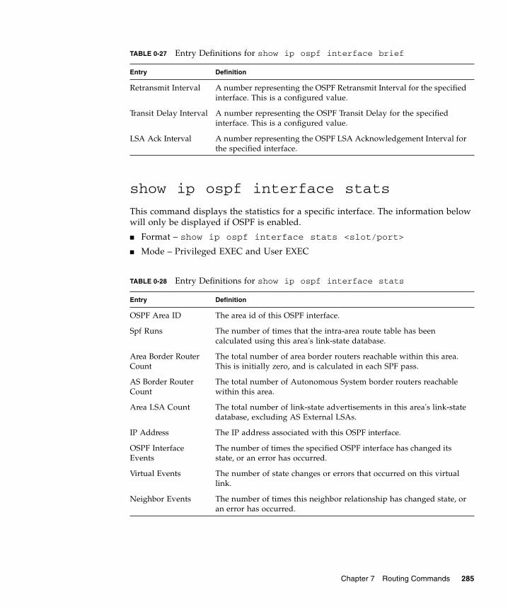
show ip ospf interface stats
This command displays the statistics for a specific interface. The information belowwill only be displayed if OSPF is enabled.
■ Format – show ip ospf interface stats <slot/port>
■ Mode – Privileged EXEC and User EXEC
Retransmit Interval A number representing the OSPF Retransmit Interval for the specifiedinterface. This is a configured value.
Transit Delay Interval A number representing the OSPF Transit Delay for the specifiedinterface. This is a configured value.
LSA Ack Interval A number representing the OSPF LSA Acknowledgement Interval forthe specified interface.
TABLE 0-28 Entry Definitions for show ip ospf interface stats
Entry Definition
OSPF Area ID The area id of this OSPF interface.
Spf Runs The number of times that the intra-area route table has beencalculated using this area's link-state database.
Area Border RouterCount
The total number of area border routers reachable within this area.This is initially zero, and is calculated in each SPF pass.
AS Border RouterCount
The total number of Autonomous System border routers reachablewithin this area.
Area LSA Count The total number of link-state advertisements in this area's link-statedatabase, excluding AS External LSAs.
IP Address The IP address associated with this OSPF interface.
OSPF InterfaceEvents
The number of times the specified OSPF interface has changed itsstate, or an error has occurred.
Virtual Events The number of state changes or errors that occurred on this virtuallink.
Neighbor Events The number of times this neighbor relationship has changed state, oran error has occurred.
TABLE 0-27 Entry Definitions for show ip ospf interface brief
Entry Definition
Chapter 7 Routing Commands 285

show ip ospf neighbor
This command displays the OSPF neighbor table list. When a particular neighbor IDis specified, detailed information about a neighbor is given. The information belowwill only be displayed if OSPF is enabled and the interface has a neighbor. The IPaddress is the IP address of the neighbor.
■ Format – show ip ospf neighbor <ipaddr> <slot/port>
■ Mode – Privileged EXEC and User EXEC
External LSA Count The number of external (LS type 5) link-state advertisements in thelink-state database.
LSAs Received The number of LSAs received.
Originate New LSAs The number of LSAs originated.
TABLE 0-29 Entry Definitions for show ip ospf neighbor
Entry Definition
Interface Valid slot and port number separated by forward slashes..
Router Id A 4-digit dotted-decimal number identifying neighbor router.
Options An integer value that indicates the optional OSPF capabilitiessupported by the neighbor. The neighbor's optional OSPF capabilitiesare also listed in its Hello packets. This enables received HelloPackets to be rejected (i.e., neighbor relationships will not even startto form) if there is a mismatch in certain crucial OSPF capabilities.
Router Priority Displays the OSPF priority for the specified interface. The priority ofan interface is a priority integer from 0 to 255. A value of '0' indicatesthat the router is not eligible to become the designated router on thisnetwork.
TABLE 0-28 Entry Definitions for show ip ospf interface stats
Entry Definition
286 Sun Netra CP3140 Switch Software Reference Manual • January 2010
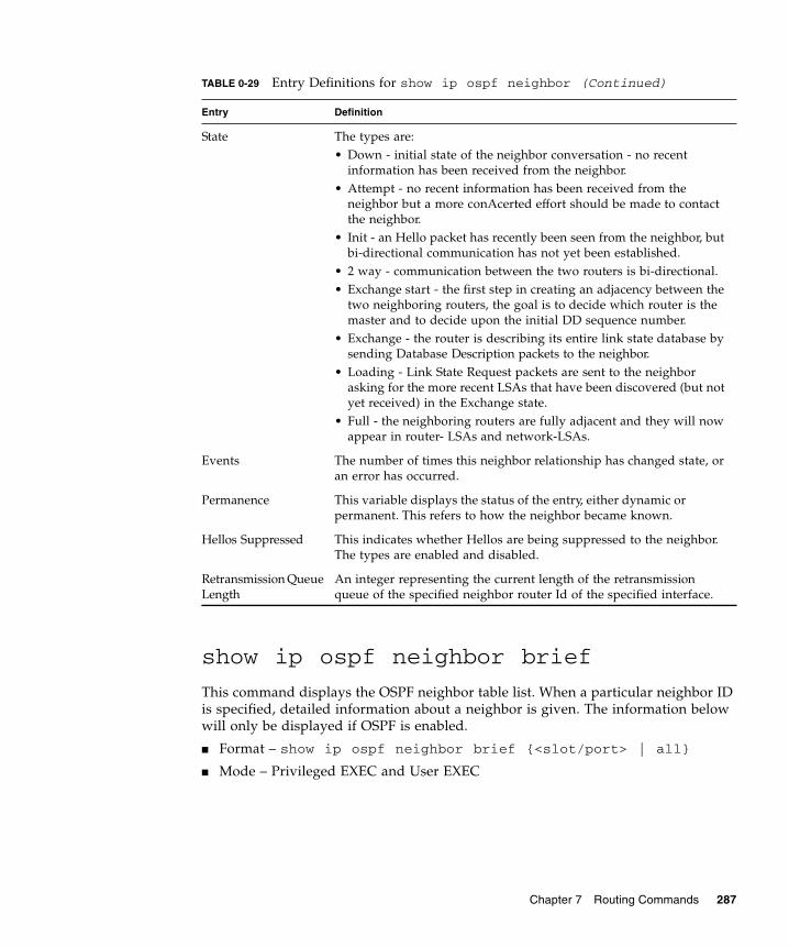
show ip ospf neighbor brief
This command displays the OSPF neighbor table list. When a particular neighbor IDis specified, detailed information about a neighbor is given. The information belowwill only be displayed if OSPF is enabled.
■ Format – show ip ospf neighbor brief {<slot/port> | all}
■ Mode – Privileged EXEC and User EXEC
State The types are:• Down - initial state of the neighbor conversation - no recent
information has been received from the neighbor.• Attempt - no recent information has been received from the
neighbor but a more conAcerted effort should be made to contactthe neighbor.
• Init - an Hello packet has recently been seen from the neighbor, butbi-directional communication has not yet been established.
• 2 way - communication between the two routers is bi-directional.• Exchange start - the first step in creating an adjacency between the
two neighboring routers, the goal is to decide which router is themaster and to decide upon the initial DD sequence number.
• Exchange - the router is describing its entire link state database bysending Database Description packets to the neighbor.
• Loading - Link State Request packets are sent to the neighborasking for the more recent LSAs that have been discovered (but notyet received) in the Exchange state.
• Full - the neighboring routers are fully adjacent and they will nowappear in router- LSAs and network-LSAs.
Events The number of times this neighbor relationship has changed state, oran error has occurred.
Permanence This variable displays the status of the entry, either dynamic orpermanent. This refers to how the neighbor became known.
Hellos Suppressed This indicates whether Hellos are being suppressed to the neighbor.The types are enabled and disabled.
Retransmission QueueLength
An integer representing the current length of the retransmissionqueue of the specified neighbor router Id of the specified interface.
TABLE 0-29 Entry Definitions for show ip ospf neighbor (Continued)
Entry Definition
Chapter 7 Routing Commands 287
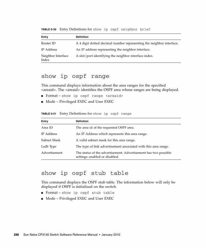
show ip ospf range
This command displays information about the area ranges for the specified<areaid>. The <areaid> identifies the OSPF area whose ranges are being displayed.
■ Format – show ip ospf range <areaid>
■ Mode – Privileged EXEC and User EXEC
show ip ospf stub table
This command displays the OSPF stub table. The information below will only bedisplayed if OSPF is initialized on the switch.
■ Format – show ip ospf stub table
■ Mode – Privileged EXEC and User EXEC
TABLE 0-30 Entry Definitions for show ip ospf neighbor brief
Entry Definition
Router ID A 4 digit dotted decimal number representing the neighbor interface.
IP Address An IP address representing the neighbor interface.
Neighbor InterfaceIndex
A slot/port identifying the neighbor interface index.
TABLE 0-31 Entry Definitions for show ip ospf range
Entry Definition
Area ID The area id of the requested OSPF area.
IP Address An IP Address which represents this area range.
Subnet Mask A valid subnet mask for this area range.
Lsdb Type The type of link advertisement associated with this area range.
Advertisement The status of the advertisement. Advertisement has two possiblesettings: enabled or disabled.
288 Sun Netra CP3140 Switch Software Reference Manual • January 2010

show ip ospf virtual-link
This command displays the OSPF Virtual Interface information for a specific areaand neighbor. The <areaid> parameter identifies the area and the <neighbor>parameter identifies the neighbor's Router ID.
■ Format – show ip ospf virtual-link <areaid> <neighbor>
■ Mode – Privileged EXEC and User EXEC
TABLE 0-32 Entry Definitions for show ip ospf stub table
Entry Definition
Area ID A 32-bit identifier for the created stub area.
Type of Service The type of service associated with the stub metric. FASTPATH onlysupports Normal TOS.
Metric Val The metric value is applied based on the TOS. It defaults to the leastmetric of the type of service among the interfaces to other areas. TheOSPF cost for a route is a function of the metric value.
Metric Type The type of metric advertised as the default route.
Import SummaryLSA
Controls the import of summary LSAs into stub areas.
TABLE 0-33 Entry Definitions for show ip ospf virtual-link
Entry Definition
Area ID The area id of the requested OSPF area.
Neighbor Router ID The input neighbor Router ID.
Hello Interval The configured hello interval for the OSPF virtual interface.
Dead Interval The configured dead interval for the OSPF virtual interface.
Iftransit DelayInterval
The configured transit delay for the OSPF virtual interface.
Retransmit Interval The configured retransmit interval for the OSPF virtual interface.
Authentication Type The configured authentication type of the OSPF virtual interface.
State The OSPF Interface States are: down, loopback, waiting, point-to-point, designated router, and backup designated router. This is thestate of the OSPF interface.
Neighbor State The neighbor state.
Chapter 7 Routing Commands 289
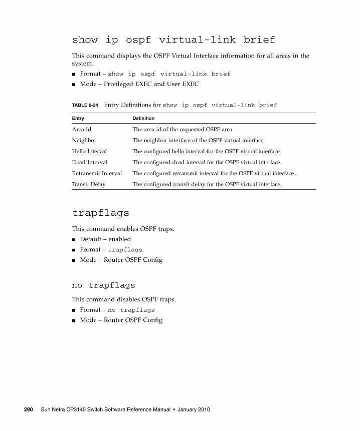
show ip ospf virtual-link brief
This command displays the OSPF Virtual Interface information for all areas in thesystem.
■ Format – show ip ospf virtual-link brief
■ Mode – Privileged EXEC and User EXEC
trapflags
This command enables OSPF traps.
■ Default – enabled
■ Format – trapflags
■ Mode – Router OSPF Config
no trapflags
This command disables OSPF traps.
■ Format – no trapflags
■ Mode – Router OSPF Config
TABLE 0-34 Entry Definitions for show ip ospf virtual-link brief
Entry Definition
Area Id The area id of the requested OSPF area.
Neighbor The neighbor interface of the OSPF virtual interface.
Hello Interval The configured hello interval for the OSPF virtual interface.
Dead Interval The configured dead interval for the OSPF virtual interface.
Retransmit Interval The configured retransmit interval for the OSPF virtual interface.
Transit Delay The configured transit delay for the OSPF virtual interface.
290 Sun Netra CP3140 Switch Software Reference Manual • January 2010
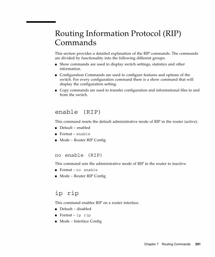
Routing Information Protocol (RIP)CommandsThis section provides a detailed explanation of the RIP commands. The commandsare divided by functionality into the following different groups:
■ Show commands are used to display switch settings, statistics and otherinformation.
■ Configuration Commands are used to configure features and options of theswitch. For every configuration command there is a show command that willdisplay the configuration setting.
■ Copy commands are used to transfer configuration and informational files to andfrom the switch.
enable (RIP)
This command resets the default administrative mode of RIP in the router (active).
■ Default – enabled
■ Format – enable
■ Mode – Router RIP Config
no enable (RIP)
This command sets the administrative mode of RIP in the router to inactive.
■ Format – no enable
■ Mode – Router RIP Config
ip rip
This command enables RIP on a router interface.
■ Default – disabled
■ Format – ip rip
■ Mode – Interface Config
Chapter 7 Routing Commands 291

no ip rip
This command disables RIP on a router interface.
■ Format – no ip rip
■ Mode – Interface Config
auto-summary
This command enables the RIP auto-summarization mode.
■ Default – enabled
■ Format – auto-summary
■ Mode – Router RIP Config
no auto-summary
This command disables the RIP auto-summarization mode.
■ Format – no auto-summary
■ Mode – Router RIP Config
default-information originate (RIP)
This command is used to control the advertisement of default routes.
■ Format – default-information originate
■ Mode – Router RIP Config
no default-information originate (RIP)
This command is used to control the advertisement of default routes.
■ Format – no default-information originate
■ Mode – Router RIP Config
default-metric (RIP)
This command is used to set a default for the metric of distributed routes.
■ Format – default-metric <0-15>
292 Sun Netra CP3140 Switch Software Reference Manual • January 2010

■ Mode – Router RIP Config
no default-metric (RIP)
This command is used to reset the default metric of distributed routes to its defaultvalue.
■ Format – no default-metric
■ Mode – Router RIP Config
distance rip
This command sets the route preference value of RIP in the router. Lower routepreference values are preferred when determining the best route.
■ Default – 15
■ Format – distance rip <0-255>
■ Mode – Router RIP Config
no distance rip
This command sets the default route preference value of RIP in the router.
■ Format – no distance rip
■ Mode – Router RIP Config
distribute-list out
This command is used to specify the access list to filter routes received from thesource protocol.
■ Default – 0
■ Format – distribute-list <1-199> out {ospf | static |connected}
■ Mode – Router RIP Config
no distribute-list out
This command is used to specify the access list to filter routes received from thesource protocol.
Chapter 7 Routing Commands 293

■ Format – no distribute-list <1-199> out {ospf | static |connected}
■ Mode – Router RIP Config
no default-information originate
This command is used to control the advertisement of default routes.
■ Format – no default-information originate
■ Mode – Router RIP Config
ip rip authentication
This command sets the RIP Version 2 Authentication Type and Key for the specifiedinterface. The value of <type> is either none, simple, or encrypt.
The value for authentication key [key] must be 16 bytes or less. The [key] iscomposed of standard displayable, non-control keystrokes from a Standard 101/102-key keyboard. If the value of <type> is encrypt, a keyid in the range of 0 and 255must be specified.
■ Defaults:
■ The default authentication type is none.
■ The default password key is an empty string. Unauthenticated interfaces donot need an authentication key.
■ The default key id is not defined. Unauthenticated interfaces do not need anauthentication key id.
■ Format – ip rip authentication {none | {simple <key>} |{encrypt <key> <keyid>}}
■ Mode – Interface Config
no ip rip authentication
This command sets the default RIP Version 2 Authentication Type.
■ Format – no ip rip authentication
■ Mode – Interface Config
294 Sun Netra CP3140 Switch Software Reference Manual • January 2010

ip rip receive version
This command configures the interface to allow RIP control packets of the specifiedversion(s) to be received.
The value for <mode> is one of: rip1 to receive only RIP version 1 formatted packets,rip2 for RIP version 2, both to receive packets from either format, or none to notallow any RIP control packets to be received.
■ Default – both
■ Format – ip rip receive version {rip1 | rip2 | both | none}
■ Mode – Interface Config
no ip rip receive version
This command configures the interface to allow RIP control packets of the defaultversion(s) to be received.
■ Format – no ip rip receive version
■ Mode – Interface Config
ip rip send version
This command configures the interface to allow RIP control packets of the specifiedversion to be sent. The value for <mode> is one of: rip1 to broadcast RIP version 1formatted packets, rip1c (RIP version 1 compatibility mode) which sends RIPversion 2 formatted packets via broadcast, rip2 for sending RIP version 2 usingmulticast, or none to not allow any RIP control packets to be sent.
■ Default – rip2
■ Format – ip rip send version {rip1 | rip1c | rip2 | none}
■ Mode – Interface Config
no ip rip send version
This command configures the interface to allow RIP control packets of the defaultversion to be sent.
■ Format – no ip rip send version
■ Mode – Interface Config
Chapter 7 Routing Commands 295
hostroutesaccept
This command enables the RIP hostroutesaccept mode.
■ Default – enabled
■ Format – hostroutesaccept
■ Mode – Router RIP Config
no hostroutesaccept
This command disables the RIP hostroutesaccept mode.
■ Format – no hostroutesaccept
■ Mode – Router RIP Config
split-horizon
This command sets the RIP split horizon mode.
■ Default – simple
■ Format – split-horizon {none | simple | poison}
■ Mode – Router RIP Config
no split-horizon
This command sets the default RIP split horizon mode.
■ Format – no split-horizon
■ Mode – Router RIP Config
redistribute
This command configures RIP protocol to redistribute routes from the specifiedsource protocol/routers. There are five possible match options. When you submitthe command redistribute ospf match <match- type> the match-type or typesspecified are added to any match types presently being redistributed. Internal routesare redistributed by default.
■ Defaults:
■ metric—not-configured
■ match—internal
296 Sun Netra CP3140 Switch Software Reference Manual • January 2010
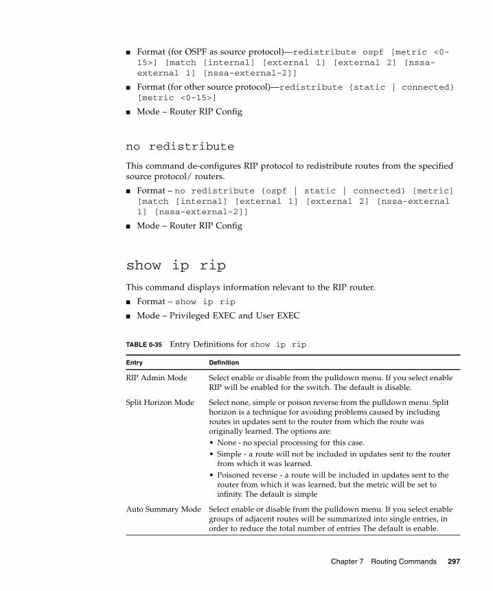
■ Format (for OSPF as source protocol)—redistribute ospf [metric <0-15>] [match [internal] [external 1] [external 2] [nssa-external 1] [nssa-external-2]]
■ Format (for other source protocol)—redistribute {static | connected}[metric <0-15>]
■ Mode – Router RIP Config
no redistribute
This command de-configures RIP protocol to redistribute routes from the specifiedsource protocol/ routers.
■ Format – no redistribute {ospf | static | connected} [metric][match [internal] [external 1] [external 2] [nssa-external1] [nssa-external-2]]
■ Mode – Router RIP Config
show ip rip
This command displays information relevant to the RIP router.
■ Format – show ip rip
■ Mode – Privileged EXEC and User EXEC
TABLE 0-35 Entry Definitions for show ip rip
Entry Definition
RIP Admin Mode Select enable or disable from the pulldown menu. If you select enableRIP will be enabled for the switch. The default is disable.
Split Horizon Mode Select none, simple or poison reverse from the pulldown menu. Splithorizon is a technique for avoiding problems caused by includingroutes in updates sent to the router from which the route wasoriginally learned. The options are:• None - no special processing for this case.• Simple - a route will not be included in updates sent to the router
from which it was learned.• Poisoned reverse - a route will be included in updates sent to the
router from which it was learned, but the metric will be set toinfinity. The default is simple
Auto Summary Mode Select enable or disable from the pulldown menu. If you select enablegroups of adjacent routes will be summarized into single entries, inorder to reduce the total number of entries The default is enable.
Chapter 7 Routing Commands 297
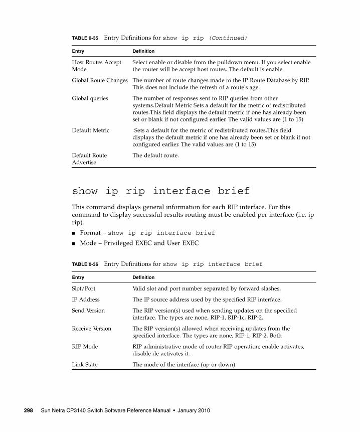
show ip rip interface brief
This command displays general information for each RIP interface. For thiscommand to display successful results routing must be enabled per interface (i.e. iprip).
■ Format – show ip rip interface brief
■ Mode – Privileged EXEC and User EXEC
Host Routes AcceptMode
Select enable or disable from the pulldown menu. If you select enablethe router will be accept host routes. The default is enable.
Global Route Changes The number of route changes made to the IP Route Database by RIP.This does not include the refresh of a route's age.
Global queries The number of responses sent to RIP queries from othersystems.Default Metric Sets a default for the metric of redistributedroutes.This field displays the default metric if one has already beenset or blank if not configured earlier. The valid values are (1 to 15)
Default Metric Sets a default for the metric of redistributed routes.This fielddisplays the default metric if one has already been set or blank if notconfigured earlier. The valid values are (1 to 15)
Default RouteAdvertise
The default route.
TABLE 0-36 Entry Definitions for show ip rip interface brief
Entry Definition
Slot/Port Valid slot and port number separated by forward slashes.
IP Address The IP source address used by the specified RIP interface.
Send Version The RIP version(s) used when sending updates on the specifiedinterface. The types are none, RIP-1, RIP-1c, RIP-2.
Receive Version The RIP version(s) allowed when receiving updates from thespecified interface. The types are none, RIP-1, RIP-2, Both
RIP Mode RIP administrative mode of router RIP operation; enable activates,disable de-activates it.
Link State The mode of the interface (up or down).
TABLE 0-35 Entry Definitions for show ip rip (Continued)
Entry Definition
298 Sun Netra CP3140 Switch Software Reference Manual • January 2010

show ip rip interface
This command displays information related to a particular RIP interface.
■ Format – show ip rip interface <slot/port>
■ Mode – Privileged EXEC and User EXEC
The following information will be invalid if the link state is down.
TABLE 0-37 Entry Definitions for show ip rip interface
Entry Definition
Interface Valid slot and port number separated by forward slashes. This is aconfigured value.
IP Address The IP source address used by the specified RIP interface. This is aconfigured value.
Send version The RIP version(s) used when sending updates on the specifiedinterface. The types are none, RIP-1, RIP-1c, RIP-2. This is aconfigured value.
Receive version The RIP version(s) allowed when receiving updates from thespecified interface. The types are none, RIP-1, RIP-2, Both. This is aconfigured value.
Both RIP AdminMode
RIP administrative mode of router RIP operation; enable activates,disable de-activates it. This is a configured value.
Link State Indicates whether the RIP interface is up or down. This is aconfigured value.
Authentication Type The RIP Authentication Type for the specified interface. The types arenone, simple, and encrypt. This is a configured value.
Default Metric A number which represents the metric used for default routes in RIPupdates originated on the specified interface. This is a configuredvalue.
TABLE 0-38 Entry Definitions for show ip rip interface With Link StateDown
Entry Definition
Bad Packets Received The number of RIP response packets received by the RIP processwhich were subsequently discarded for any reason.
Bad Routes Received The number of routes contained in valid RIP packets that wereignored for any reason.
Updates Sent The number of triggered RIP updates actually sent on this interface.
Chapter 7 Routing Commands 299

300 Sun Netra CP3140 Switch Software Reference Manual • January 2010
APPENDIX A
Configuration Examples
This appendix contains the following configuration examples:
■ “IEEE 802.1Q VLAN” on page 301
■ “VLAN Routing” on page 306
■ “STP, RSTP and MSTP Configuration” on page 308
■ “Sun Netra CP3140 VRRP Configuration” on page 310
IEEE 802.1Q VLANLAN switches can segment networks into logically defined virtual workgroups. Thislogical segmentation is commonly referred as a virtual LAN (VLAN). This logicalsegmentation of devices provides better LAN administration, security, andmanagement of broadcast activity over the network. Virtual LANs have become anintegral feature of switched LAN solutions.
The VLAN example in TABLE A-1 demonstrates a simple VLAN configuration withFASTPATH. If a single port is a member of VLANs 2, 3, and 4, the port expects to seetraffic tagged with either VLAN 2, 3, or 4.
The PVID (Port Virtual Identification) could be something entirely different, forexample 12, and things would still work fine, just so incoming traffic was tagged.
Example Projects:
■ Project A = (VLAN2, ports 1, 2)
■ Project B = (VLAN3, ports 3, 4)
■ Project C = (VLAN4, ports 5, 6)
■ Project P = (VLAN 9, port 7)
301

TABLE A-1 Creating VLANs
VLAN Commands
Create VLAN 2 vlan database
vlan 2
exit
config
interface 0/1
vlan participation vlan tagging 2/3/4/9include 2
vlan tagging 2
exit
interface 0/2
vlan participation vlan tagging 2/3/4/9include 2
vlan tagging 2
exit
Create VLAN 3 vlan database
vlan 3
exit
config
interface 0/3
vlan participation vlan tagging 2/3/4/9include 3
vlan tagging 3
exit
interface 0/4
vlan participation include 3
vlan tagging 3
exit
302 Sun Netra CP3140 Switch Software Reference Manual • January 2010

Create VLAN 4 vlan database
vlan 4
exit
config
interface 0/5
vlan participation include 4
vlan tagging 4
exit
interface 0/6
vlan participation include 4
vlan tagging 4
exit
TABLE A-1 Creating VLANs (Continued)
VLAN Commands
Appendix A Configuration Examples 303

VLAN Solution 1All traffic entering the ports is tagged traffic. Since the traffic is tagged, the PVIDconfiguration for each port is not a concern.
■ The network card configuration for devices on Project A (VLAN2, ports 1, 2) mustbe set to tag all traffic with VLAN2.
Create VLAN 9 vlan database
vlan 9
exit
config
interface 0/1
vlan participation include 9
vlan tagging 9
exit
interface 0/2
vlan participation include 9
vlan tagging 9
exit
interface 0/3
vlan participation include 9
vlan tagging 9
exit
interface 0/4
vlan participation include 9
vlan tagging 9
exit
interface 0/5
vlan participation include 9
vlan tagging 9
exit
interface 0/6
vlan participation include 9
vlan tagging 9
exit
interface 0/7
vlan participation include 9
vlan tagging 9
exit
TABLE A-1 Creating VLANs (Continued)
VLAN Commands
304 Sun Netra CP3140 Switch Software Reference Manual • January 2010
■ The network card configuration for devices on Project B (VLAN3, ports 3, 4) mustbe set to tag all traffic with VLAN3.
■ The network card configuration for devices on Project C (VLAN4, ports 5, 6) mustbe set to tag all traffic with VLAN4.
■ The network card configuration for devices on Project P (VLAN 9, port 7) must beset to tag all traffic with VLAN9.
VLAN Solution 2The network card configuration for devices on Project A, B and C should be set toNOT tag traffic.
To take care of these untagged frames, configure the following:
■ vlan pvid 2 (in interface 0/1)
■ vlan pvid 2 (in interface 0/2)
■ vlan pvid 3 (in interface 0/3)
■ vlan pvid 3 (in interface 0/4)
■ vlan pvid 4 (in interface 0/5)
■ vlan pvid 4 (in interface 0/6)
Note – Refer to the release notes for the FASTPATH application level code. Therelease notes detail the platform specific functionality of the Switching, Routing,SNMP, Config, Management, and Bandwidth Provisioning packages. The suite offeatures supported by the FASTPATH packages are not available on all the platformsto which FASTPATH has been ported.
Appendix A Configuration Examples 305
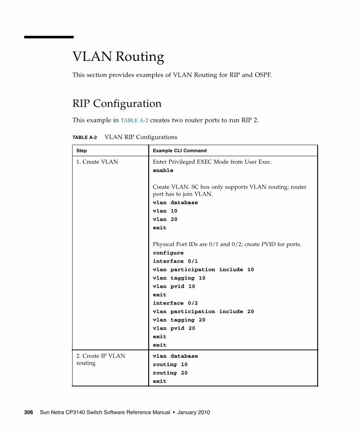
VLAN RoutingThis section provides examples of VLAN Routing for RIP and OSPF.
RIP ConfigurationThis example in TABLE A-2 creates two router ports to run RIP 2.
TABLE A-2 VLAN RIP Configurations
Step Example CLI Command
1. Create VLAN Enter Privileged EXEC Mode from User Exec.enable
Create VLAN. SC box only supports VLAN routing; routerport has to join VLAN.vlan database
vlan 10
vlan 20
exit
Physical Port IDs are 0/1 and 0/2; create PVID for ports.configure
interface 0/1
vlan participation include 10
vlan tagging 10
vlan pvid 10
exit
interface 0/2
vlan participation include 20
vlan tagging 20
vlan pvid 20
exit
exit
2. Create IP VLANrouting
vlan database
routing 10
routing 20
exit
306 Sun Netra CP3140 Switch Software Reference Manual • January 2010

3. Enable the routingfunction for the virtualrouter
configure
ip routing
4. Configure Router ID(virtual)
router ospf
router-id 192.168.111.50
exit
5. Configure IP interface(virtual)
Assign IP to router port 4/1 and 4/2.interface 4/1
ip address 9.1.1.1 255.0 0 0
exit
interface 4/2
ip address 192.168.111.1 255.255.255.0
exit
6. Enable OSPF protocol router ospf
enable
exit
interface 4/1
ip ospf
exit
interface 4/2
ip ospf
exit
TABLE A-2 VLAN RIP Configurations (Continued)
Step Example CLI Command
Appendix A Configuration Examples 307
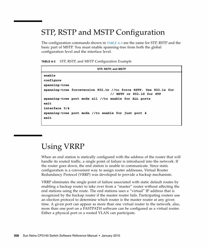
STP, RSTP and MSTP ConfigurationThe configuration commands shown in TABLE A-3 are the same for STP, RSTP and thebasic part of MSTP. You must enable spanning-tree from both the globalconfiguration level and the interface level.
Using VRRPWhen an end station is statically configured with the address of the router that willhandle its routed traffic, a single point of failure is introduced into the network. Ifthe router goes down, the end station is unable to communicate. Since staticconfiguration is a convenient way to assign router addresses, Virtual RouterRedundancy Protocol (VRRP) was developed to provide a backup mechanism.
VRRP eliminates the single point of failure associated with static default routes byenabling a backup router to take over from a “master” router without affecting theend stations using the route. The end stations uses a “virtual” IP address that isrecognized by the backup router if the master router fails. Participating routers usean election protocol to determine which router is the master router at any giventime. A given port can appear as more than one virtual router to the network, also,more than one port on a FASTPATH software can be configured as a virtual router.Either a physical port or a routed VLAN can participate.
TABLE A-3 STP, RSTP, and MSTP Configuration Example
STP, RSTP, and MSTP
enable
configure
spanning-tree
spanning-tree forceversion 802.1w //to force RSTP. Use 802.1s for// MSTP or 802.1d for STP
spanning-tree port mode all //to enable for ALL ports
exit
interface 0/4
spanning-tree port mode //to enable for just port 4
exit
308 Sun Netra CP3140 Switch Software Reference Manual • January 2010
Setting Up VRRP on the Sun Netra CP3140VRRP provides redundant gateways in an L3 routed network. If Sun Netra CP3140board is used as an L2 only switch, there is no reason to use VRRP. If L3 routing isused, then VRRP can be used.
A Sun Netra CT 900 chassis can be equipped with maximum of two Sun NetraCP3140 boards. A user can configure the two Sun Netra CP3140 boards in eachchassis as redundant gateways for the node boards in the same chassis, or the usercan group multiple chassis into a layer 2 network and then use the Sun NetraCP3140 boards in one chassis as the redundant gateways for all the node boards inthe group.
A user may not also configure Sun Netra CP3140 boards as redundant gateways,instead a pair or a set of external routers can be used to provide VRRP facility to aset of Sun Netra CT 900 chassis. In such configuration, Sun Netra CP3140 boards areused as L2 switches only.
The L2 requirements for a VRRP configuration involving Sun Netra CT 900 chassisare the following:
■ An ATCA node interface should be reachable to all the VRRP enabled switchcards in its L2 network. When the VRRP master router fails, a node board shouldhave an L2 path to the VRRP backup routers.
■ There should be L2 reachability between VRRP master and backup routers forheartbeating. The Sun Netra CP3140 board interconnect can be used for thispurpose if two switch cards in a chassis are used as VRRP master and backup.
For example, if a Sun Netra CP3140 board is set up as router for a node board in thesame Sun Netra CT 900 chassis and that Sun Netra CP3140 board fails, the nodeboard can not reach any other network element via the interface connected to thefailed Sun Netra CP3140 board. Even if there is a backup router set up using VRRP,it won’t be reachable via that interface. In such configuration, the only solution is toconfigure a bonding interface on top of the two base/fabric interfaces. With abonding interface solution, the node can reach the backup router (that is, the otherSun Netra CP3140 board in the chassis) via the interface connected to the backuprouter.
A network involving multiple Sun Netra CT 900 chassis with redundant paths to theVRRP enabled Sun Netra CP3140s can have multiple broadcast loops. Therefore, it isimportant to configure the Spanning Tree Protocol on the Sun Netra CP3140 board ina loop.
Appendix A Configuration Examples 309
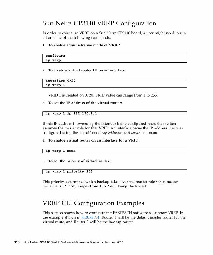
Sun Netra CP3140 VRRP ConfigurationIn order to configure VRRP on a Sun Netra CP3140 board, a user might need to runall or some of the following commands:
1. To enable administrative mode of VRRP
2. To create a virtual router ID on an interface:
VRID 1 is created on 0/20. VRID value can range from 1 to 255.
3. To set the IP address of the virtual router:
If this IP address is owned by the interface being configured, then that switchassumes the master role for that VRID. An interface owns the IP address that wasconfigured using the ip address <ip-address> <netmask> command
4. To enable virtual router on an interface for a VRID:
5. To set the priority of virtual router:
This priority determines which backup takes over the master role when masterrouter fails. Priority ranges from 1 to 254, 1 being the lowest.
VRRP CLI Configuration ExamplesThis section shows how to configure the FASTPATH software to support VRRP. Inthe example shown in FIGURE A-1, Router 1 will be the default master router for thevirtual route, and Router 2 will be the backup router.
configureip vrrp
interface 0/20ip vrrp 1
ip vrrp 1 ip 192.150.2.1
ip vrrp 1 mode
ip vrrp 1 priority 253
310 Sun Netra CP3140 Switch Software Reference Manual • January 2010
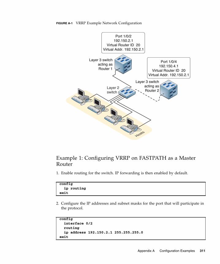
FIGURE A-1 VRRP Example Network Configuration
Example 1: Configuring VRRP on FASTPATH as a MasterRouter
1. Enable routing for the switch. IP forwarding is then enabled by default.
2. Configure the IP addresses and subnet masks for the port that will participate inthe protocol.
config ip routingexit
config interface 0/2 routing ip address 192.150.2.1 255.255.255.0exit
Hosts
Layer 2switch
Layer 3 switchacting asRouter 1
Layer 3 switchacting asRouter 2
Port 1/0/2192.150.2.1
Virtual Router ID 20Virtual Addr. 192.150.2.1
Port 1/0/4192.150.4.1
Virtual Router ID 20Virtual Addr. 192.150.2.1
Appendix A Configuration Examples 311

3. Enable VRRP for the switch.
4. Assign virtual router IDs to the port that will participate in the protocol.
5. Specify the IP address that the virtual router function will recognize. Note thatthe virtual IP address on port 1/0/2 is the same as the port’s actual IP address,therefore this router will always be the VRRP master when it is active. And thepriority default is 255.
6. Enable VRRP on the port.
Example 2: Configuring VRRP on FASTPATH as a BackupRouter
1. Enable routing for the switch. IP forwarding is then enabled by default.
2. Configure the IP addresses and subnet masks for the port that will participate inthe protocol.
config ip vrrpexit
config interface 0/2 ip vrrp 20
ip vrrp 20 ip 192.150.2.1
ip vrrp 20 modeexit
config ip routingexit
config interface 0/4 routing ip address 192.150.4.1 255.255.255.0exit
312 Sun Netra CP3140 Switch Software Reference Manual • January 2010
3. Enable VRRP for the switch.
4. Assign virtual router IDs to the port that will participate in the protocol.
5. Specify the IP address that the virtual router function will recognize. Since thevirtual IP address on port 1/0/4 is the same as Router 1’s port 1/0/2 actual IPaddress, this router will always be the VRRP backup when Router 1 is active.
6. Set the priority for the port. The default priority is 100.
7. Enable VRRP on the port.
config ip vrrp 20exit
config interface 0/4 ip vrrp 20
ip vrrp 20 ip 192.150.2.1
ip vrrp 20 priority 254
ip vrrp 20 modeexit
Appendix A Configuration Examples 313

314 Sun Netra CP3140 Switch Software Reference Manual • January 2010

APPENDIX B
Using RADIUS
Making use of a single database of accessible information – as in an AuthenticationServer – can greatly simplify the authentication and management of users in a largenetwork. One such type of Authentication Server supports the RemoteAuthentication Dial-In User Service (RADIUS) protocol as defined by RFC 2865.
For authenticating users prior to access, the RADIUS standard has become theprotocol of choice by administrators of large accessible networks. To accomplish theauthentication in a secure manner, the RADIUS client and RADIUS server must bothbe configured with the same shared password or secret. This secret is used togenerate one-way encrypted authenticators that are present in all RADIUS packets.The secret is never transmitted over the network.
RADIUS conforms to a secure communications client/server model using UDP as atransport protocol. It is extremely flexible, supporting a variety of methods toauthenticate and statistically track users. RADIUS is also extensible, allowing fornew methods of authentication to be added without disrupting existingfunctionality.
As a user attempts to connect to a functioning RADIUS supported network, a devicereferred to as the Network Access Server (NAS) or switch/router first detects thecontact. The NAS or user-login interface then prompts the user for a name andpassword. The NAS encrypts the supplied information and a RADIUS clienttransports the request to a preconfigured RADIUS server. The server canauthenticate the user itself, or make use of a back-end device to ascertainauthenticity. In either case a response might or might not be forthcoming to theclient. If the server accepts the user, it returns a positive result with attributescontaining configuration information. If the server rejects the user, it returns anegative result. If the server rejects the client or the shared secrets differ, the serverreturns no result. If the server requires additional verification from the user, itreturns a challenge, and the request process begins again.
315
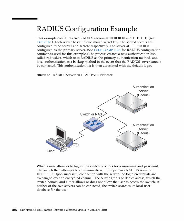
RADIUS Configuration ExampleThis example configures two RADIUS servers at 10.10.10.10 and 11.11.11.11 (seeFIGURE B-1). Each server has a unique shared secret key. The shared secrets areconfigured to be secret1 and secret2 respectively. The server at 10.10.10.10 isconfigured as the primary server. (See CODE EXAMPLE B-1 for RADIUS configurationcommands used for this example.) The process creates a new authentication list,called radiusList, which uses RADIUS as the primary authentication method, andlocal authentication as a backup method in the event that the RADIUS server cannotbe contacted. This authentication list is then associated with the default login.
FIGURE B-1 RADIUS Servers in a FASTPATH Network
When a user attempts to log in, the switch prompts for a username and password.The switch then attempts to communicate with the primary RADIUS server at10.10.10.10. Upon successful connection with the server, the login credentials areexchanged over an encrypted channel. The server grants or denies access, which theswitch honors, and either allows or does not allow the user to access the switch. Ifneither of the two servers can be contacted, the switch searches its local userdatabase for the use.
ESCAPE
ENTER
ESCAPE
ENTER
Client
Switch or NAS
Authenticationserver
(Radius)
Authenticationserver
(Radius)
316 Sun Netra CP3140 Switch Software Reference Manual • January 2010

CODE EXAMPLE B-1 RADIUS Configuration Example
configradius server host auth 10.10.10.10radius server key auth 10.10.10.10
secret1secret1
radius server host auth 11.11.11.11radius server key auth 11.11.11.11
secret2secret2
radius server primary 10.10.10.10authentication login radiusList radius localusers defaultlogin radiusList
exit
Appendix B Using RADIUS 317

318 Sun Netra CP3140 Switch Software Reference Manual • January 2010
APPENDIX C
Management Security
In the past, network communications were simply a matter of packaging frames ofinformation and shipping them over the wire to their destination. Protocols gavelittle thought to who might be viewing the frames as they crossed the wire, or whatillegitimate parties might do with the information so gleaned. More and more,security has become an ever-present concern amongst the members of thenetworking community. Networking infrastructure is far too important to risk abuseby hackers, whether they are malevolent or simply mischievous. As a whole, thecommunity has turned to encryption as a means of insuring the security of networktransactions.
Interactive login is a mainstay for providing a means to control and/or configure anentity across the network. For decades the Telnet protocol has provided thiscapability for devices wishing to provide interactive login over a network. However,these protocols are chief culprits with regard to the transmission of sensitiveinformation (like passwords) over the network unprotected. The current de factostandard for providing interactive login in a secure fashion is the Secure Shell (SSH).SSH provides a number of services in a secure manner. These include portforwarding, file transfer, X11 forwarding, and interactive login. Of these, currentlyonly interactive login is of interest for the Sun Netra CP3140 switch.
Managing devices with a web browser has been standard practice for several years.Unfortunately, standard HTTP transactions are no more secure than Telnet. This wasone of the original barriers to the success of "e-commerce". The solution (then andnow) is the use of the Secure Sockets Layer (SSL) protocol. SSL provides a means ofabstracting an encrypted connection between two stations. Once established, such aconnection is virtually no different to use than an unsecured connection. This allowsan established protocol (like HTTP) to operate in a secure manner in an opennetwork. A third component of management on a modern networking appliance isSNMP. The SNMP protocol has it own security mechanisms outside of SSH and SSL.Consequently discussion of security for SNMP transactions is outside the scope ofthis chapter.
319

Enabling Management SecurityEnabling management security is a two-step process. The first step involvesgenerating and loading appropriate authentication keys (SSH) and securitycertificates (SSL). Optionally, a reputable third party such as RSA Security, Inc. orEntrust, Inc. can validate these certificates and keys, but for evaluation purposesvalidation is unnecessary. The second step involves enabling either SSL or SSH andoptionally disabling the insecure versions of Telnet and web management. Onceenabled, subsequent management connections may be made in a secure manner.
Certificate GenerationTo generate self-signed credentials, the open source applications ssh-keygen andopenssl can be used to create the seven files used to form the security certificatesand authentication keys. Both of these applications are well documented by the opensource community. Detailed descriptions will not be repeated here as you can checkthe man pages for detailed help. Two scripts are included at the end of this appendixalong with some helper files. This set of files can be freely modified and used togenerate the appropriate self-signed credentials. Generation of these credentials hasbeen verified using both cygwin and Linux.
Once the component files are created, the credentials must be loaded onto the SunNetra CP3140 switch. This is accomplished by using the copy command from aTFTP server. From privileged EXEC mode, issue the following command:
Where the IP address of the TFTP server should be substituted as appropriate. Thiscopy command is repeated for all the authentication components:
■ rsa1.key nvram:sshkey-rsa1
■ rsa2.key nvram:sshkey-rsa2
■ dsa.key nvram:sshkey-dsa
■ dh512.pem nvram:sslpem-dhweak
■ dh1024.pem nvram:sslpem-dhstrong
■ server.pem nvram:sslpem-server
■ rootcert.pem nvram:sslpem-root
copy tftp://192.168.77.122/rsa1.key nvram:sshkey-rsa1
320 Sun Netra CP3140 Switch Software Reference Manual • January 2010

The SSL and SSH credentials may be uploaded separately as needed. It is likely thatif security is required for one access method it would be required for all accessmethods. Thus it is recommended that the certificates and authentication key becreated simultaneously.
Configuring Secure ShellOnce the authentication credentials are loaded and the certificates andauthentication keys are formed, management security may be configured on theFASTPATH device. From privileged EXEC mode, issue the command:
This allows Secure Shell sessions to be instantiated on the Sun Netra CP3140. Themessage log should be checked for errors if a secure connection cannot beestablished. Entries such as the following indicate the nature of the problem.
In this case, the authentication credentials were invalid and should be regenerated.Messages indicating successful start of the SSH service look like this:
ip ssh
0 days 02:30:30 File: ssh_sys_fastpath.c : Line: 584 : tid40052584, context 0x0x157dba0, deleting 40052584, retval = 10 days 02:30:30 File: ssh_sys_fastpath.c : Line: 401 : SSHD:exiting global context 0x0x157dba00 days 02:30:30 File: sshd_main.c : Line: 550 : SSHD: host key iscorrupt (did not decode).
0 days 00:17:07 Unit: 1 : File: sshd_main.c : Line: 349 : SSHD:Done generating server key0 days 00:17:06 Unit: 1 : File: sshd_main.c : Line: 639 : SSHD:successfully loaded RSA2 key0 days 00:17:06 Unit: 1 : File: sshd_main.c : Line: 627 : SSHD:successfully opened file ssh_host_rsa_key0 days 00:17:06 Unit: 1 : File: sshd_main.c : Line: 605 : SSHD:successfully loaded DSA key0 days 00:17:06 Unit: 1 : File: sshd_main.c : Line: 592 : SSHD:successfully opened file ssh_host_dsa_key0 days 00:17:06 Unit: 1 : File: sshd_control.c : Line: 400 : SSHD:sshdListenTask started
Appendix C Management Security 321
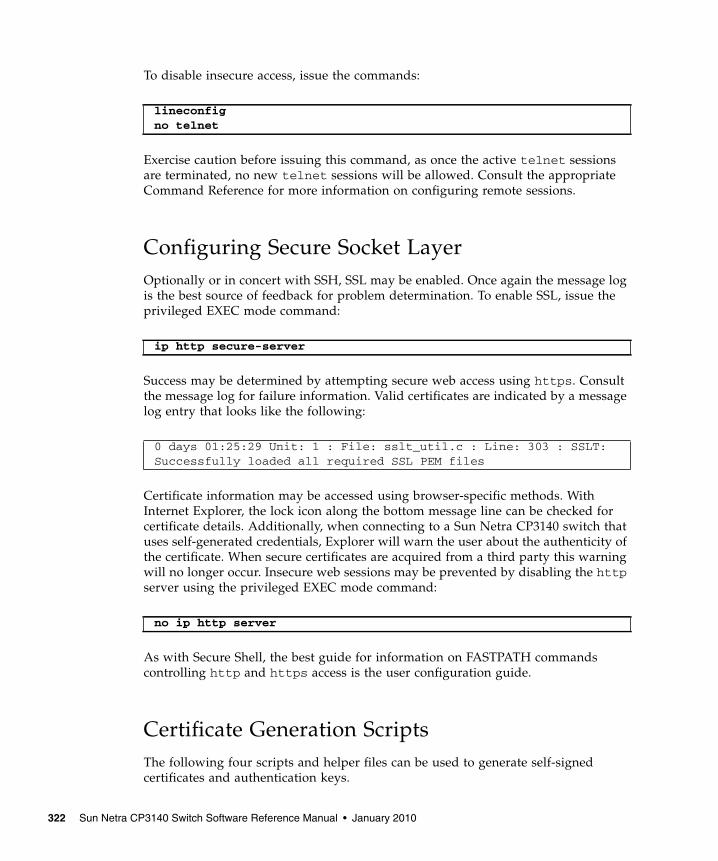
To disable insecure access, issue the commands:
Exercise caution before issuing this command, as once the active telnet sessionsare terminated, no new telnet sessions will be allowed. Consult the appropriateCommand Reference for more information on configuring remote sessions.
Configuring Secure Socket LayerOptionally or in concert with SSH, SSL may be enabled. Once again the message logis the best source of feedback for problem determination. To enable SSL, issue theprivileged EXEC mode command:
Success may be determined by attempting secure web access using https. Consultthe message log for failure information. Valid certificates are indicated by a messagelog entry that looks like the following:
Certificate information may be accessed using browser-specific methods. WithInternet Explorer, the lock icon along the bottom message line can be checked forcertificate details. Additionally, when connecting to a Sun Netra CP3140 switch thatuses self-generated credentials, Explorer will warn the user about the authenticity ofthe certificate. When secure certificates are acquired from a third party this warningwill no longer occur. Insecure web sessions may be prevented by disabling the httpserver using the privileged EXEC mode command:
As with Secure Shell, the best guide for information on FASTPATH commandscontrolling http and https access is the user configuration guide.
Certificate Generation ScriptsThe following four scripts and helper files can be used to generate self-signedcertificates and authentication keys.
lineconfigno telnet
ip http secure-server
0 days 01:25:29 Unit: 1 : File: sslt_util.c : Line: 303 : SSLT:Successfully loaded all required SSL PEM files
no ip http server
322 Sun Netra CP3140 Switch Software Reference Manual • January 2010
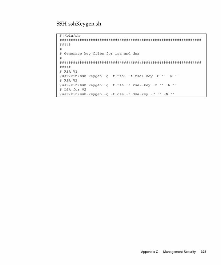
SSH sshKeygen.sh
#!/bin/sh####################################################################### Generate key files for rsa and dsa####################################################################### RSA V1/usr/bin/ssh-keygen -q -t rsa1 -f rsa1.key -C '' -N ''# RSA V2/usr/bin/ssh-keygen -q -t rsa -f rsa2.key -C '' -N ''# DSA for V2/usr/bin/ssh-keygen -q -t dsa -f dsa.key -C '' -N ''
Appendix C Management Security 323
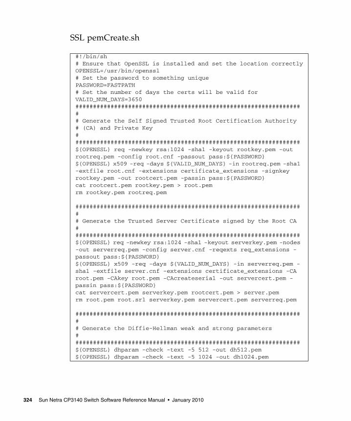
SSL pemCreate.sh
#!/bin/sh# Ensure that OpenSSL is installed and set the location correctlyOPENSSL=/usr/bin/openssl# Set the password to something uniquePASSWORD=FASTPATH# Set the number of days the certs will be valid forVALID_NUM_DAYS=3650################################################################## Generate the Self Signed Trusted Root Certification Authority# (CA) and Private Key#################################################################${OPENSSL} req -newkey rsa:1024 -sha1 -keyout rootkey.pem -outrootreq.pem -config root.cnf -passout pass:${PASSWORD}${OPENSSL} x509 -req -days ${VALID_NUM_DAYS} -in rootreq.pem -sha1-extfile root.cnf -extensions certificate_extensions -signkeyrootkey.pem -out rootcert.pem -passin pass:${PASSWORD}cat rootcert.pem rootkey.pem > root.pemrm rootkey.pem rootreq.pem
################################################################## Generate the Trusted Server Certificate signed by the Root CA#################################################################${OPENSSL} req -newkey rsa:1024 -sha1 -keyout serverkey.pem -nodes-out serverreq.pem -config server.cnf -reqexts req_extensions -passout pass:${PASSWORD}${OPENSSL} x509 -req -days ${VALID_NUM_DAYS} -in serverreq.pem -sha1 -extfile server.cnf -extensions certificate_extensions -CAroot.pem -CAkey root.pem -CAcreateserial -out servercert.pem -passin pass:${PASSWORD}cat servercert.pem serverkey.pem rootcert.pem > server.pemrm root.pem root.srl serverkey.pem servercert.pem serverreq.pem
################################################################## Generate the Diffie-Hellman weak and strong parameters#################################################################${OPENSSL} dhparam -check -text -5 512 -out dh512.pem${OPENSSL} dhparam -check -text -5 1024 -out dh1024.pem
324 Sun Netra CP3140 Switch Software Reference Manual • January 2010

SSL root.cnf
# default settings for DTI example.[ ca ]default_ca = dtica[ dtica ]dir = /opt/dticacertificate = $dir/cacert.pemdatabase = $dir/index.txtnew_certs_dir = $dir/certsprivate_key = $dir/private/cakey.pemserial = $dir/serialdefault_crl_days = 7default_days = 365default_md = sha1policy = dtica_policyx509_extensions = certificate_extensions[ dtica_policy ]commonName = suppliedstateOrProvinceName = suppliedcountryName = suppliedemailAddress = suppliedorganizationName = suppliedorganizationalUnitName = supplied[ req ]default_bits = 2048default_keyfile = privkey.pemdefault_md = sha1prompt = nodistinguished_name = req_distinguished_namex509_extensions = req_extensions# the following sections are specific to the request being built[ certificate_extensions ]basicConstraints = CA:truesubjectKeyIdentifier=hashauthorityKeyIdentifier=keyid:always,issuer:always[ req_distinguished_name ]countryName = USstateOrProvinceName = MississippilocalityName = RidgelandorganizationName = Diversified Technology, Inc.organizationalUnitName = SupportcommonName = DTI Root CAemailAddress = [email protected][ req_extensions ]basicConstraints = CA:true
Appendix C Management Security 325

SSH server.cnf
# default settings for DTI example.[ ca ]default_ca = dtica[ dtica ]dir = /opt/edticacertificate = $dir/cacert.pemdatabase = $dir/index.txtnew_certs_dir = $dir/certsprivate_key = $dir/private/cakey.pemserial = $dir/serialdefault_crl_days = 7default_days = 365default_md = sha1policy = dtica_policyx509_extensions = certificate_extensions[ dtica_policy ]countryName = suppliedstateOrProvinceName = suppliedlocalityName = suppliedorganizationName = suppliedorganizationalUnitName = suppliedcommonName = suppliedemailAddress = supplied[ req ]default_bits = 2048default_keyfile = privkey.pemdefault_md = sha1prompt = nodistinguished_name = req_distinguished_namex509_extensions = req_extensions# the following sections are specific to the request being built[ certificate_extensions ]basicConstraints = CA:falsesubjectAltName = DNS:localhost[ req_distinguished_name ]countryName = USstateOrProvinceName = MississippilocalityName = ridgelandorganizationName = Diversified Technology, Inc.organizationalUnitName = SupportcommonName = localhostemailAddress = [email protected][ req_extensions ]basicConstraints = CA:truesubjectAltName = DNS:localhostdistinguished_name =req_distinguished_name
326 Sun Netra CP3140 Switch Software Reference Manual • January 2010

APPENDIX D
uBoot Software
This appendix describes the uBoot software on the Sun Netra CP3140 switch boardand includes the following topics:
■ “uBoot Overview” on page 327
■ “Boot Utility Menu” on page 330
■ “Network Booting” on page 333
uBoot OverviewThe uBoot software is the boot loader for the switch. Much like a BIOS, it brings thesystem to a usable state for the operating system to boot. It also performs a power-on self-test (POST) of the CPU subsystem. It can be used as a recovery console if thefirmware image is corrupt or a firmware update fails. Several importantenvironment variables are stored in uBoot, only some of which should ever bechanged, namely noekey and baudrate.
uBoot ConsoleTo get to a uBoot console, you must prevent the switch from booting into Linux.Shown here is the start of the switch boot sequence.
CPU: 400 MHzDRAM: 128 MBFLASH: 32 MBBooting ...
327
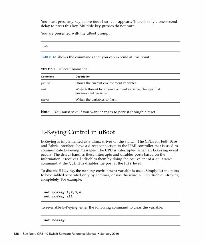
You must press any key before Booting ... appears. There is only a one-seconddelay to press this key. Multiple key presses do not hurt.
You are presented with the uBoot prompt:
TABLE D-1 shows the commands that you can execute at this point.
Note – You must save if you want changes to persist through a reset.
E-Keying Control in uBootE-Keying is implemented as a Linux driver on the switch. The CPUs for both Baseand Fabric interfaces have a direct connection to the IPMI controller that is used tocommunicate E-Keying messages. The CPU is interrupted when an E-Keying eventoccurs. The driver handles these interrupts and disables ports based on theinformation it receives. It disables them by doing the equivalent of a shutdowncommand at the CLI. This disables the port at the PHY level.
To disable E-Keying, the noekey environment variable is used. Simply list the portsto be disabled separated only by commas, or use the word all to disable E-Keyingcompletely. For example:
To re-enable E-Keying, enter the following command to clear the variable.
=>
TABLE D-1 uBoot Commands
Command Description
print Shows the current environment variables.
set When followed by an environment variable, changes thatenvironment variable.
save Writes the variables to flash.
set noekey 1,2,3,4set noekey all
set noekey
328 Sun Netra CP3140 Switch Software Reference Manual • January 2010
After changing the environment variables, you must always save if you would likeyour change to persist though a reset.
Serial Baud Rate Control in uBootThe serial baud rate can be changed from within FASTPATH, on the boot menu, orin uBoot. Only changes made in uBoot will persist through a reset. To change thebaud rate in uBoot, the baudrate variable must be changed. Only standard baudrates are accepted.
To change the baud rate in uBoot, enter:
After changing the environment variables, you must always save if you would likeyour change to persist though a reset.
Boot SequenceFollowing is an example of the switch boot sequence.
set baudrate 115200
Appendix D uBoot Software 329

The switch should take approximately 20 seconds to boot to a console and be fullyfunctional.
Boot Utility MenuThere is a utility menu that can be used before FASTPATH boots. As seen in thepreceding section, during boot, a two-option menu is displayed for five seconds.This menu enables you to access to the utility menu if you press 2 and Return.
The following screen is displayed once you enter the boot utility menu.
CPU: 400 MHzDRAM: 128 MBFLASH: 32 MB
Booting ...
Boot Menu v1.0
Select startup mode. If no selection is made within 5 seconds,the Switch-Router Application will start automatically...
Switch-Router Startup -- Main Menu
1 - Start Switch-Router Application2 - Display Utility MenuSelect (1, 2):
Copying Application to RAM...done.
Starting Application...1 File: bootos.c Line: 243 Task: 111ca6f4 EC: 2863311530(0xaaaaaaaa)(0 d 0 hrs 0 min 17 sec)Switch-Router Starting...|PCI device BCM5695_B0 attached as unit 0.\PCI device BCM5695_B0 attached as unit 1.Switch-Router Started!
(Unit 1)>User:
330 Sun Netra CP3140 Switch Software Reference Manual • January 2010
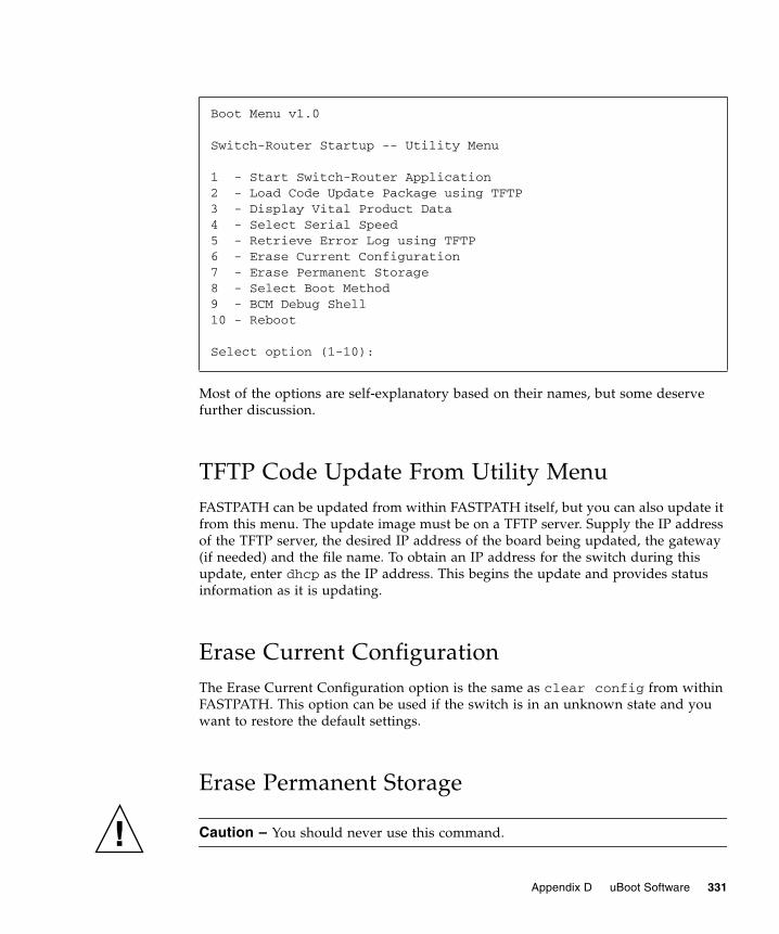
Most of the options are self-explanatory based on their names, but some deservefurther discussion.
TFTP Code Update From Utility MenuFASTPATH can be updated from within FASTPATH itself, but you can also update itfrom this menu. The update image must be on a TFTP server. Supply the IP addressof the TFTP server, the desired IP address of the board being updated, the gateway(if needed) and the file name. To obtain an IP address for the switch during thisupdate, enter dhcp as the IP address. This begins the update and provides statusinformation as it is updating.
Erase Current ConfigurationThe Erase Current Configuration option is the same as clear config from withinFASTPATH. This option can be used if the switch is in an unknown state and youwant to restore the default settings.
Erase Permanent Storage
Caution – You should never use this command.
Boot Menu v1.0
Switch-Router Startup -- Utility Menu
1 - Start Switch-Router Application2 - Load Code Update Package using TFTP3 - Display Vital Product Data4 - Select Serial Speed5 - Retrieve Error Log using TFTP6 - Erase Current Configuration7 - Erase Permanent Storage8 - Select Boot Method9 - BCM Debug Shell10 - Reboot
Select option (1-10):
Appendix D uBoot Software 331

The Erase Permanent Storage command completely erases FASTPATH, any log files,and any configurations. It does not erase uBoot or Linux. Updates can safely beinstalled without running this option, and configurations and log files are preserved.
Boot MethodThe switch supports three boot methods:
■ From the local image on the Compact Flash card■ From an image over the network■ From an image over the serial port
The default option is booting from the Compact Flash card. See “Network Booting”on page 333 for more information on network booting.
BCM Debug Shell
Note – This environment is provided as is, with no support.
The BCM Debug Shell option boots the Broadcom diag shell, currently SDK version5.2.1. Several commands provided in this shell are not supported on the switch anddo not work. This shell is provided mainly for debug, testing, and diagnosticspurposes. This shell has many low-level tests and low-level register access. It can beused to check the integrity of particular boards. Help is provided in the shell with?? and commands followed by a single question mark. Some commands of interestare SystemSnake, dsanity, TestList, and TestRun.
Note that ports are not numbered in the same order here as in FASTPATH. In theBCM diag shell, the ports are the actual port numbers of the chips. In FASTPATH,the port numbers have been abstracted to represent the ATCA channel numbers.TABLE D-2 maps the BCM diag shell numbers to the FASTPATH numbers.
TABLE D-2 BCM Diag Shell to FASTPATH Mapping
Port # in BCM Debug Shell Base Port Fabric Port
Chip 0 port 0 13 1
Chip 0 port 1 14 2
Chip 0 port 2 15 3
Chip 0 port 3 16 4
Chip 0 port 4 12 5
332 Sun Netra CP3140 Switch Software Reference Manual • January 2010
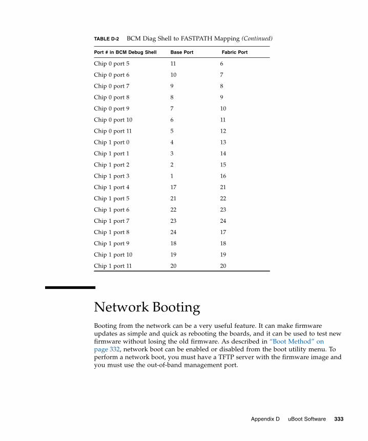
Network BootingBooting from the network can be a very useful feature. It can make firmwareupdates as simple and quick as rebooting the boards, and it can be used to test newfirmware without losing the old firmware. As described in “Boot Method” onpage 332, network boot can be enabled or disabled from the boot utility menu. Toperform a network boot, you must have a TFTP server with the firmware image andyou must use the out-of-band management port.
Chip 0 port 5 11 6
Chip 0 port 6 10 7
Chip 0 port 7 9 8
Chip 0 port 8 8 9
Chip 0 port 9 7 10
Chip 0 port 10 6 11
Chip 0 port 11 5 12
Chip 1 port 0 4 13
Chip 1 port 1 3 14
Chip 1 port 2 2 15
Chip 1 port 3 1 16
Chip 1 port 4 17 21
Chip 1 port 5 21 22
Chip 1 port 6 22 23
Chip 1 port 7 23 24
Chip 1 port 8 24 17
Chip 1 port 9 18 18
Chip 1 port 10 19 19
Chip 1 port 11 20 20
TABLE D-2 BCM Diag Shell to FASTPATH Mapping (Continued)
Port # in BCM Debug Shell Base Port Fabric Port
Appendix D uBoot Software 333
The network boot supports DHCP to obtain an IP address. Simply use dhcp as theIP address when configuring network boot. The network boot uses the out-of-bandmanagement port to download the firmware image, and then frees it to be used asnormal once FASTPATH boots. This enables an NMSto control the firmware revisionon the switch as well as manage and control the switch functions.
334 Sun Netra CP3140 Switch Software Reference Manual • January 2010

APPENDIX E
Firmware Updating Procedures
This appendix describes the firmware updating procedures for the switch andincludes the following topics:
■ “Overview” on page 335
■ “Testing Updates Before Installing Them” on page 336
■ “Updating the Switch Firmware Through the Boot Utility Menu” on page 338
■ “Updating the Switch Firmware Through the FASTPATH Software” onpage 341
OverviewFollowing is the list of firmware that is on the switch:
■ IPMC firmware
■ Base firmware
■ Base U-Boot loader
■ Base Linux operating system
■ Base FASTPATH
■ Fabric firmware
■ Fabric U-Boot boot loader
■ Fabric Linux operating system
■ Fabric FASTPATH
All of the firmware listed are field upgradable. There is a single update image thatsupports the Base firmware, Fabric firmware, and IPMC firmware. This updateimage must be installed twice: once on the Base and once on the Fabric. The IPMC
335
update happens during a Base update. Each component listed above can be updatedindependently without affecting the other components; for example, the FASTPATHcomponent can be updated without affecting the uBoot and Linux components.
Testing Updates Before Installing ThemThe switch supports network booting. This feature can be used to test updates toFASTPATH without installing them. Updates containing changes to U-Boot, Linux,or the IPMC must be installed to the flash before they can be used.
1. Set up a TFTP server on the update network.
The update network is the network where the update image is stored.
2. Place the update image on the TFTP server.
The update image will have a .tgz file extension.
3. Connect to the serial management port of the Base or Fabric network to beupdated and connect the MGMT port to the update network.
4. Reset the switch.
Following are the different methods that you can use to reset the switch:
■ Press the reset button on the switch.
■ Disengage and reengage the card injector/ejector mechanisms at the top andbottom of the card.
■ Execute the reload command through the switch software.
5. As the switch resets, press 2 to enter the Utility Menu.
6. Press 8 to change the boot method.
7. Press 3 to select network as the boot method.
8. Enter the necessary information for your TFTP server.
For the host IP field, you can enter dhcp if you would like to use DHCP to obtaina valid IP address.
9. Press 1 to boot the system.
Use option 8 of the Utility Menu to change the boot method back to flash, ifnecessary.
CODE EXAMPLE E-1 an example of the console output (note that there might be slightvariations depending on the settings and the software versions).
336 Sun Netra CP3140 Switch Software Reference Manual • January 2010

CODE EXAMPLE E-1 Sample Output for Network Booting
CPU: 400 MHzDRAM: 128 MBFLASH: 32 MB
Booting ...
Boot Menu v1.5
Select startup mode. If no selection is made within 5 seconds,the Switch-Router Application will start automatically...
Switch-Router Startup -- Main Menu
1 - Start Switch-Router Application2 - Display Utility MenuSelect (1, 2): 2
Boot Menu v1.0
Switch-Router Startup -- Utility Menu
1 - Start Switch-Router Application 2 - Load Code Update Package using TFTP 3 - Display Vital Product Data 4 - Select Serial Speed 5 - Retrieve Error Log using TFTP 6 - Erase Current Configuration 7 - Erase Permanent Storage 8 - Select Boot Method 9 - BCM Debug Shell 10 - Reboot
Select option (1-10): 8
Current boot method: FLASH1 - Flash Boot2 - Network Boot3 - Exit without changeSelect option (1-3): 2Enter Server IP []: 10.10.3.199Enter Host IP []: dhcpEnter Gateway IP []:Enter Filename []: /p/atscp3140.1.4.1.1.tgzAccept changes? Press(Y/N): y
Appendix E Firmware Updating Procedures 337
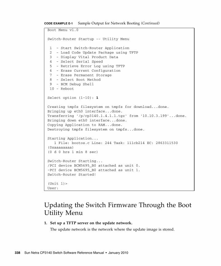
Updating the Switch Firmware Through the BootUtility Menu1. Set up a TFTP server on the update network.
The update network is the network where the update image is stored.
Boot Menu v1.0
Switch-Router Startup -- Utility Menu
1 - Start Switch-Router Application 2 - Load Code Update Package using TFTP 3 - Display Vital Product Data 4 - Select Serial Speed 5 - Retrieve Error Log using TFTP 6 - Erase Current Configuration 7 - Erase Permanent Storage 8 - Select Boot Method 9 - BCM Debug Shell 10 - Reboot
Select option (1-10): 1
Creating tmpfs filesystem on tmpfs for download...done.Bringing up eth0 interface...done.Transferring '/p/cp3140.1.4.1.1.tgz' from '10.10.3.199'...done.Bringing down eth0 interface...done.Copying Application to RAM...done.Destroying tmpfs filesystem on tmpfs...done.
Starting Application... 1 File: bootos.c Line: 244 Task: 111cb214 EC: 2863311530(0xaaaaaaaa)(0 d 0 hrs 1 min 8 sec)
Switch-Router Starting.../PCI device BCM5695_B0 attached as unit 0.-PCI device BCM5695_B0 attached as unit 1.Switch-Router Started!
(Unit 1)>User:
CODE EXAMPLE E-1 Sample Output for Network Booting (Continued)
338 Sun Netra CP3140 Switch Software Reference Manual • January 2010

2. Place the update image on the TFTP server.
The update image will have a .tgz file extension.
3. Connect to the serial management port of the Base or Fabric network to beupdated and connect the MGMT port to the update network.
4. Reset the switch.
Following are the different methods that you can use to reset the switch:
■ Press the reset button on the switch
■ Disengage and reengage the card injector/ejector mechanisms at the top andbottom of the card
■ Execute the reload command through the switch software
5. As the switch resets, press 2 to enter the Utility Menu.
6. Press 2 to choose to update the firmware through TFTP.
7. Enter the necessary information for your TFTP server.
For the host IP field, you can enter dhcp if you would like to use DHCP to obtaina valid IP address.
8. Once the update is complete, reset the switch.
If the update is only for the FASTPATH software, you do not need to reboot andcan press 1 instead.
9. Repeat these steps for the other network interface.
CODE EXAMPLE E-2 is an example of the console output (note that there might beslight variations depending on the settings and the software versions).
CODE EXAMPLE E-2 Sample Output for Updating Firmware Using the Boot Utility Menu
CPU: 400 MHzDRAM: 128 MBFLASH: 32 MB
Booting ...
Boot Menu v1.5
Select startup mode. If no selection is made within 5 seconds,the Switch-Router Application will start automatically...
Switch-Router Startup -- Main Menu
1 - Start Switch-Router Application2 - Display Utility Menu
Appendix E Firmware Updating Procedures 339
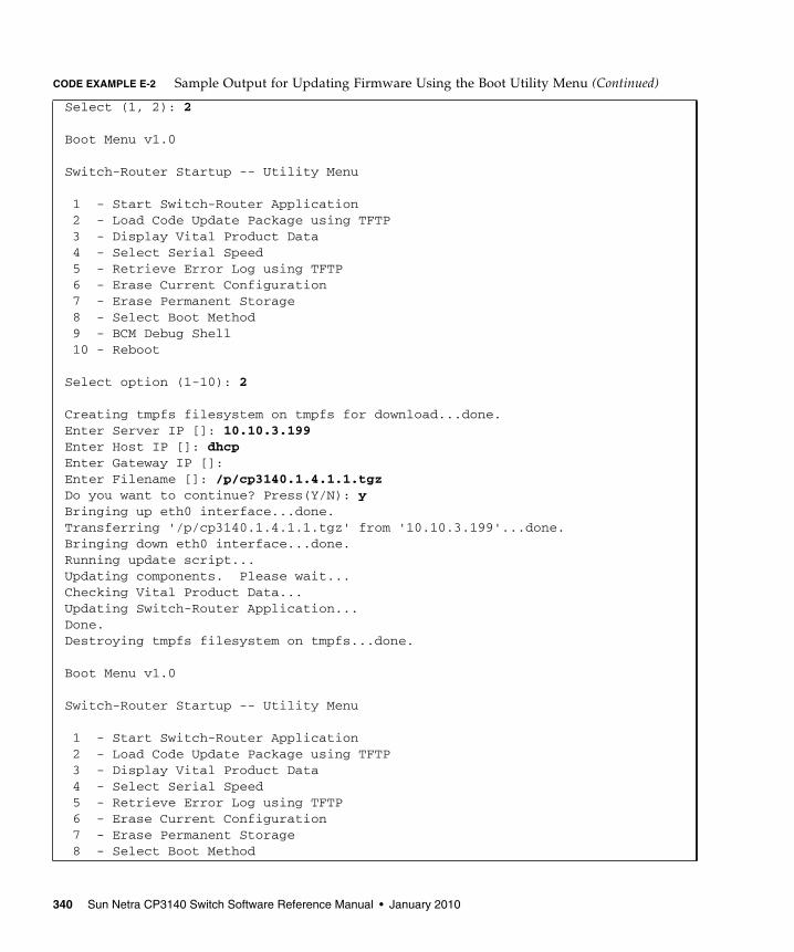
Select (1, 2): 2
Boot Menu v1.0
Switch-Router Startup -- Utility Menu
1 - Start Switch-Router Application 2 - Load Code Update Package using TFTP 3 - Display Vital Product Data 4 - Select Serial Speed 5 - Retrieve Error Log using TFTP 6 - Erase Current Configuration 7 - Erase Permanent Storage 8 - Select Boot Method 9 - BCM Debug Shell 10 - Reboot
Select option (1-10): 2
Creating tmpfs filesystem on tmpfs for download...done.Enter Server IP []: 10.10.3.199Enter Host IP []: dhcpEnter Gateway IP []:Enter Filename []: /p/cp3140.1.4.1.1.tgzDo you want to continue? Press(Y/N): yBringing up eth0 interface...done.Transferring '/p/cp3140.1.4.1.1.tgz' from '10.10.3.199'...done.Bringing down eth0 interface...done.Running update script...Updating components. Please wait...Checking Vital Product Data...Updating Switch-Router Application...Done.Destroying tmpfs filesystem on tmpfs...done.
Boot Menu v1.0
Switch-Router Startup -- Utility Menu
1 - Start Switch-Router Application 2 - Load Code Update Package using TFTP 3 - Display Vital Product Data 4 - Select Serial Speed 5 - Retrieve Error Log using TFTP 6 - Erase Current Configuration 7 - Erase Permanent Storage 8 - Select Boot Method
CODE EXAMPLE E-2 Sample Output for Updating Firmware Using the Boot Utility Menu (Continued)
340 Sun Netra CP3140 Switch Software Reference Manual • January 2010

Updating the Switch Firmware Through theFASTPATH SoftwareThese instructions cover all firmware updates initiated through the FASTPATHsoftware.
1. Set up a TFTP server on the update network.
The update network is the network where the update image is stored.
2. Place the update image on the TFTP server.
The update image will have a .tgz file extension.
3. Determine if you are using telnet, SSH, or SNMP.
■ If you are using telnet, SSH, or SNMP, skip to Step 7.
■ If you are not using telnet, SSH, or SNMP, then continue with Step 4.
4. Connect to the serial management port of the Base or Fabric network to beupdated.
5. Log in to the switch.
6. Configure the network of the switch that you are upgrading.
You can configure the network using either the out-of-band management or thein-band network.
■ If you are using the out-of-band management, connect the MGMT port, eitherthrough the front panel of the switch or through the rear transition card, tothe update network.
■ If you are using DHCP, enter the following command:
9 - BCM Debug Shell 10 - Reboot
Select option (1-10): 10Rebooting...syncing filesystems....This may take a few momentsumount: forced umount of (null) failed!Rebooting system!The system is going down NOW !!Sending SIGKILL to all processes.Please stand by while rebooting the system.
serviceport protocol dhcp
CODE EXAMPLE E-2 Sample Output for Updating Firmware Using the Boot Utility Menu (Continued)
Appendix E Firmware Updating Procedures 341
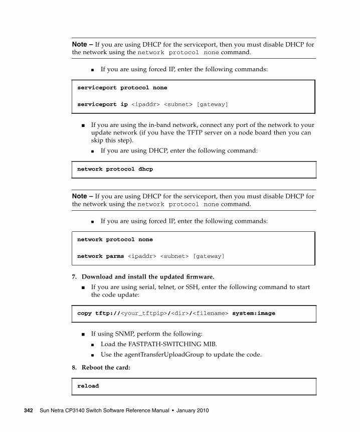
Note – If you are using DHCP for the serviceport, then you must disable DHCP forthe network using the network protocol none command.
■ If you are using forced IP, enter the following commands:
■ If you are using the in-band network, connect any port of the network to yourupdate network (if you have the TFTP server on a node board then you canskip this step).
■ If you are using DHCP, enter the following command:
Note – If you are using DHCP for the serviceport, then you must disable DHCP forthe network using the network protocol none command.
■ If you are using forced IP, enter the following commands:
7. Download and install the updated firmware.
■ If you are using serial, telnet, or SSH, enter the following command to startthe code update:
■ If using SNMP, perform the following:
■ Load the FASTPATH-SWITCHING MIB.
■ Use the agentTransferUploadGroup to update the code.
8. Reboot the card:
serviceport protocol none
serviceport ip <ipaddr> <subnet> [gateway]
network protocol dhcp
network protocol none
network parms <ipaddr> <subnet> [gateway]
copy tftp://<your_tftpip>/<dir>/<filename> system:image
reload
342 Sun Netra CP3140 Switch Software Reference Manual • January 2010
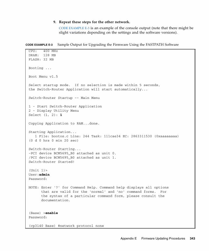
9. Repeat these steps for the other network.
CODE EXAMPLE E-3 is an example of the console output (note that there might beslight variations depending on the settings and the software versions).
CODE EXAMPLE E-3 Sample Output for Upgrading the Firmware Using the FASTPATH Software
CPU: 400 MHzDRAM: 128 MBFLASH: 32 MB
Booting ...
Boot Menu v1.5
Select startup mode. If no selection is made within 5 seconds,the Switch-Router Application will start automatically...
Switch-Router Startup -- Main Menu
1 - Start Switch-Router Application2 - Display Utility MenuSelect (1, 2): 1
Copying Application to RAM...done.
Starting Application... 1 File: bootos.c Line: 244 Task: 111cae34 EC: 2863311530 (0xaaaaaaaa)(0 d 0 hrs 0 min 20 sec)
Switch-Router Starting...-PCI device BCM5695_B0 attached as unit 0./PCI device BCM5695_B0 attached as unit 1.Switch-Router Started!
(Unit 1)>User:adminPassword:
NOTE: Enter '?' for Command Help. Command help displays all options that are valid for the 'normal' and 'no' command forms. For the syntax of a particular command form, please consult the documentation.
(Base) >enablePassword:
(cp3140 Base) #network protocol none
Appendix E Firmware Updating Procedures 343

Changing protocol mode will reset ip configuration.Are you sure you want to continue? (y/n) y
(Base) #serviceport protocol dhcp
Changing protocol mode will reset ip configuration.Are you sure you want to continue? (y/n) y
(Base) #show serviceport
IP Address..................................... 10.10.3.3Subnet Mask.................................... 255.255.254.0Default Gateway................................ 10.10.2.1ServPort Configured Protocol Current........... DHCPBurned In MAC Address.......................... 00:20:13:F0:BB:E8
(Base) #copy tftp://10.10.3.199/p/cp3140.1.4.1.1.tgz system:image
Mode........................................... TFTPSet TFTP Server IP............................. 10.10.3.199TFTP Path...................................... p/TFTP Filename.................................. cp3140.1.4.1.1.tgzData Type...................................... Code
Are you sure you want to start? (y/n) yTFTP Code transfer starting...Updating components. Please wait...Extracting components...Checking Vital Product Data...Updating Switch-Router Application...Done.
File transfer operation completed successfully.
(Base) #reload
CODE EXAMPLE E-3 Sample Output for Upgrading the Firmware Using the FASTPATH Software
344 Sun Netra CP3140 Switch Software Reference Manual • January 2010
Glossary
Knowledge of the following terms and acronyms is useful in the administration ofthe Netra CT 900 server.
AATCA (Advanced Telecom Computing Architecture) Also referred to as
AdvancedTCA®. A series of industry standard specifications for the nextgeneration of carrier grade communications equipment. AdvancedTCAincorporates the latest trends in high speed interconnect technologies, nextgeneration processors, and improved reliability, manageability andserviceability, resulting in a new blade (board) and chassis (shelf) form factoroptimized for communications at the lowest cost due to standardization.
Bbackup shelf
management card Any shelf management card capable of assuming support for the shelfmanager function.
Base channel A physical connection within the Base interface composed of up to fourdifferential signal pairs. Each Base channel is the endpoint of a slot-to-slotconnection within the base interface.
Base switch A switch that supports the Base interface. A Base switch provides10/100/1000BASE-T packet switching services to all node boards installed inthe shelf. In the Netra CT 900 server, the Base switches reside in physical slots
345
7 and 8 (logical slots 1 and 2) in the shelf and support connections to all nodeslots and boards. Boards that support the Fabric interface and Base interfaceare also referred to as “switches.”
Base interface An interface that is used to support 10/100 or 1000BASE-T connectionsbetween node boards and switches in a shelf. Midplanes are required tosupport the Base interface by routing four different signal pairs between allnode board slots and each switch slot (in the Netra CT 900 server, the Baseswitch slots are physical slots 7 and 8, logical slots 1 and 2).
Ddata transport
interface A collection of point-to-point interfaces and bused signals intended to provideinterconnect among the payloads on switches and node boards.
Dual Star topology An interconnect fabric topology in which two switch resources provideredundant connections to all end points within the network. A pair of switchesprovide redundant interconnects between node boards.
EElectronic Keying or
E-Keying A protocol used to describe the compatibility between the Base interface,Fabric interface, update channel interface, and synchronization clocksconnections of front boards.
ETSI European Telecommunications Standards Institute.
FFabric channel A Fabric channel is comprised of two rows of signal pairs for a total of eight
signal pairs per channel. Thus, each connector supports up to five channelsavailable for board to board connectivity. A channel may also be viewed asbeing comprised of four 2-pair ports.
Fabric interface A Zone 2 interface that provides 15 connections per board or slot, eachcomprising up to 8 differential signal pairs (channels) supporting connectionswith up to 15 other slots or boards. Midplanes can support the Fabric interface
346 Sun Netra CP3140 Switch Software Reference Manual • January 2010
in a variety of configurations including Full Mesh and Dual Star topologies.Boards that support the Fabric interface can be configured as fabric nodeboards, fabric switches, or mesh-enabled boards. Board implementations of theFabric interface are defined by the PICMG® 3.x subsidiary specifications.
field-replaceable unit(FRU) From a service point of view, the smallest irreducible elements of a server.
Examples of FRUs are disk drives, I/O cards, and power entry modules. Notethat a server, with all of its cards and other components, is not a FRU.However, an empty server is a FRU.
frame A physical or logical entity that can contain one or more shelves. Also called arack, or, if enclosed, a cabinet.
front board A board that conforms to PICMG 3.0 mechanicals (8U x280mm), including aPCB and a panel. A front board connects with the Zone 1 and Zone 2 midplaneconnectors. It can optionally connect with a Zone 3 midplane connector ordirectly to a rear transition card connector and is installed into the frontposition in the shelf.
Full channel A Fabric channel connection that uses all eight differential signal pairs betweenend-points.
Full Mesh topology A Full Mesh configuration that can be supported within the Fabric interface toprovide one dedicated channel of connectivity between each pair of slotswithin a shelf. Full Mesh-configured midplanes are capable of supportingmesh-enabled boards or switches and node boards installed in a Dual Stararrangement.
Hhot-swap The connection and disconnection of peripherals or other components without
interrupting system operation. This facility may have design implications forboth hardware and software.
II2C Inter-integrated circuit bus. A multi-master, 2-wire serial bus used as the basis
for current IPMBs.
IPMB (Intelligent Platform Management Bus) The lowest level hardwaremanagement bus as described in the Intelligent Platform Management BusCommunications Protocol specification.
Glossary 347

IPMB-0 hub A hub device that provides multiple radial IPMB-0 links to various FRUs in thesystem. For example, an IPMB-0 hub is present in an ShMC that has radialIPMB-0 links.
IPMB-0 link With radial topology, the physical IPMB-0 segment between an IPMB-0segment between an IPMB-0 hub and a single FRU. Each IPMB-0 link on anIPMB-0 hub is usually associated with a separate IPMB-0 sensor. An IPMB-0link can also connect in a bused topology to multiple FRUs.
IPM controller(IPMC) The portion of a FRU that interfaces to the ATCA IPMB-0 and represents that
FRU and any device subsidiary to it.
IPMI (Intelligent Platform Management Interface) A specification and mechanismfor providing inventory management, monitoring, logging, and control forelements of a computer system. As defined in Intelligent PlatformManagement Interface specification.
Llogic ground A shelf-wide electrical net used on boards and midplanes as a reference and
return path for logic-level signals that are carried between boards.
MMesh Enabled board A board that provides connectivity to all other boards within the midplane.
Mesh Enabled boards support the Fabric interface and can also support theBase interface. Mesh Enabled boards can use 2 to 15 Fabric interface channels(typically all 15 channels) to support direct connections to all other boards inthe shelf. The number of channels supported dictate the maximum number ofboards that can be connected to within a shelf. Mesh Enabled boards that donot use the Base interface can be installed in the lowest available logical slot.Mesh Enabled boards supporting the Base interface can be Base switches, inwhich case they can support Base channels 1 and 2 and can be installed intological slots 3 to 16. Boards supporting the Base interface use Base channels 1and 2 only to support 10/100/1000BASE-T Ethernet.
midplane The functional equivalent of a backplane. The midplane is secured to the backof the server. The CPU card, I/O cards, and storage devices connect to themidplane from the front, and the rear transition cards connect to the midplanefrom the rear.
348 Sun Netra CP3140 Switch Software Reference Manual • January 2010

NNEBS (Network Equipment/Building System) A set of requirements for equipment
installed in telecommunications control offices in the United States. Theserequirements cover personnel safety, protection of property, and operationalcontinuity. NEBS testing involves subjecting equipment to various vibrationstresses, fire, and other environmental and quality metrics. There are threelevels of NEBS compliance, each a superset of the preceding. NEBS level 3, thehighest level, certifies that a piece of equipment can be safely deployed in an“extreme environment.” A telecommunications central office is considered anextreme environment.
The NEBS standards are maintained by Telcordia Technologies, Inc., formerlyBellcore.
node board A board intended for use in a star topology midplane that has connectivity to aswitch within the midplane. Node boards can support either or both the Baseinterface and Fabric interface. Boards supporting the Fabric interface use Fabricchannels 1 and 2. Boards supporting the Base interface use Base channels 1 and2 only to support 10/100/1000BASE-T Ethernet.
node slot A slot in the midplane that supports only node boards. A node slot is notcapable of supporting a switch, thus a node board can never occupy logicalslots 1 and 2. Node slots apply only to midplanes designed to support startopologies. Node slots support both the Base interface and Fabric interface.Typically, a node slot supports two or four Fabric channels and Base channels 1and 2. Each two channel node slots establish connections to logical slots 1 and2, respectively. Four channel node slots establish connections to logical slots 1,2, 3, and 4, respectively.
PPCI (Peripheral Component Interconnect) A standard for connecting peripherals to
a computer. It runs at 20 - 33 MHz and carries 32 bits at a time over a 124-pinconnector or 64 bits over a 188-pin connector. An address is sent in one cyclefollowed by one word of data (or several in burst mode).
Technically, PCI is not a bus but a bridge or mezzanine. It includes buffers todecouple the CPU from relatively slow peripherals and allow them to operateasynchronously.
physical address An address that defines the physical slot location of a FRU. A physical addressconsists of a site type and site number.
Glossary 349

PICMG (PCI Industrial Computer Manufacturers Group) A consortium of companieswho develop open specifications for telecommunications and industrialcomputing applications, including the CompactPCI standard.
Rrear-access A configuration option for the Netra CT 900 server in which all of the cables
come out from the back of the shelf.
rear transition card A card used only on the rear-access models of the Netra CT 900 server toextend the connectors to the back of the shelf.
Reliability, Availability,Serviceability (RAS) A hardware and software feature that implements or improves the reliability,
availability and serviceability of a server.
Sshelf A collection of components that consists of the midplane, front boards, cooling
devices, rear transition cards, and power entry modules. The shelf washistorically known as a chassis.
shelf address A variable length, variable format descriptor of up to 20 bytes in length thatprovides a unique identifier for each shelf within a management domain.
shelf ground A safety ground and earth return that is connected to the frame and isavailable to all boards.
shelf manager The entity in the system that is responsible for managing the power, cooling,and interconnects (with Electronic Keying) in an AdvancedTCA shelf. Theshelf manager also routes messages between the System Manager Interface andIPMB-0, provides interfaces to system repositories, and responds to eventmessages. The shelf manager can be partially or wholly deployed on the ShMCor System Manager Hardware.
ShMC (Shelf Management Controller) An IPMC that is also capable of supporting thefunctions required of the shelf manager.
SNMP Simple Network Management Protocol.
star topology A midplane topology having one or more hub slots providing connectivityamong the supported node slots.
350 Sun Netra CP3140 Switch Software Reference Manual • January 2010

switch A board intended for use in a star topology midplane that providesconnectivity to a number of node boards within the midplane. Switches cansupport either or both the Base interface and Fabric interface. Boards utilizingthe Fabric interface typically provide switching resources to all 15 availableFabric channels. Switches supporting the Base interface are installed intological slots 1 and 2 and use all 16 Base channels to provide 10/100/1000BASE-T Ethernet switching resources to up to 14 node boards and the other switch.One Base channel is assigned to support a connection to the shelf managementcard.
switch slot In a star topology midplane, switch slots must reside in logical slots 1 and 2.Switch slots support both the Base interface and Fabric interface. Switch slotslocated in logical sots 1 and 2 are capable of supporting both Base interface andFabric interface switches. Logical slots 1 and 2 are always switch slotsregardless of the fabric topology. These slots support up to 16 Base channelsand up to 15 Fabric channels each.
system A managed entity that can include one or more of the following components:node and switches, shelves, and frames.
UU A unit of measure equal to 1.75 in. (44.45 mm).
update channelinterface Also referred to as the update channel. A Zone 2 interface that provides
connections comprising of ten differential signal pairs between two boards.This direct connection between two boards can be used to synchronize stateinformation. The transport implemented for the update channel on a board isnot defined. Update channels can be used only by two like-function boardscreated by a single vendor. Electronic Keying is used to ensure that updatechannel end points have matching transport protocols mapped prior toenabling the drivers. Midplanes must support the update channel. Boards cansupport the update channel.
ZZone 1 The linear space along the height dimension of an ATCA slot that is allocated
for power, management, and other ancillary functions.
Zone 2 The linear space along the height dimension of an ATCA slot that is allocatedto the data transport interface.
Glossary 351

Zone 3 The linear space along the height dimension of an ATCA slot that is reservedfor user-defined connections and/or interconnections to the rear transitioncards for rear access systems.
352 Sun Netra CP3140 Switch Software Reference Manual • January 2010
Index
Numerics1583compatibility, 264
Aaccess-list, 188addport, 70area default-cost, 265area nssa, 265area nssa default-info-originate, 266area nssa no-redistribute (OSPF), 266area nssa no-summary (OSPF), 266area nssa translator-role (OSPF), 266area nssa translator-stab-intv, 267area range, 267area stub, 267area stub summarylsa, 268area virtual-link, 268area virtual-link authentication, 269area virtual-link dead-interval, 269area virtual-link hello-interval, 270area virtual-link retransmit-
interval, 270area virtual-link transmit-delay, 271arp, 230arp cachesize, 230arp dynamicrenew, 231arp purge, 231arp resptime, 231arp retries, 232arp timeout, 232
authentication login, 102auto-negotiate, 70auto-negotiate all, 71auto-summary, 292
Bbandwidth kbps, 209bandwidth percent, 210bootfile, 133bootpdhcprelay cidoptmode, 246bootpdhcprelay enable, 246bootpdhcprelay maxhopcount, 247bootpdhcprelay minwaittime, 247bootpdhcprelay serverip, 248bridge aging-time, 49bwallocation, 190, 191Bwprovisioning bwallocation mode, 30Bwprovisioning Config command mode, 24Bwprovisioning Config mode, 29Bwprovisioning Trafficclass mode, 29Bwprovisioning-bwallocation Config command
mode, 25Bwprovisioning-Trafficclass Config command
mode, 25
Ccablestatus, 70character strings, 12class, 210Class Map Config command mode, 24
353

Class Map mode, 28class-map, 199class-map rename, 201classofservice dot1pmapping, 146clear arp-cache, 233clear config, 21, 93clear counters, 93clear dot1x statistics, 103clear igmpsnooping, 94clear ip dhcp binding, 141clear ip dhcp conflict, 141clear ip dhcp server statistics, 141clear pass, 94clear port-channel, 94clear radius statistics, 103clear traplog, 94clear vlan, 95client-identifier, 127client-name, 128command conventions, 10command modes
Bwprovisioning Config, 24Bwprovisioning-bwallocation Config, 25Bwprovisioning-Trafficclass Config, 25Class Map Config, 24DHCP Pool Config, 25Global Config, 23Interface Config, 24Line Config, 24Policy Class Config, 24Policy Map Config, 24Privileged Exec, 23Router BGP Config, 24Router OSPF Config, 24Router RIP Config, 24User Exec, 23VLAN, 23
configuration examples, 301VLAN, 301VLAN routing, 306VRRP, 311, 312
copy, 20, 21, 96copy system, 18, 21
Ddefault-information originate
(OSPF), 271default-information originate (RIP), 292default-metric (OSPF), 272default-metric (RIP), 292default-router, 128deleteport (Global Config), 71deleteport (Interface Config), 71DHCP Pool Config command mode, 25DHCP Pool Config mode, 30diffserv, 198disconnect, 97displaying
software version information, 16distance ospf, 272distance rip, 293distribute-list out, 273, 293dns-server, 129domain-name, 133dot1x defaultlogin, 103dot1x initialize, 103dot1x login, 104dot1x max-req, 104dot1x port-control, 104dot1x port-control All, 105dot1x re-authenticate, 106dot1x re-authentication, 106dot1x system-auth-control, 106dot1x timeout, 107dot1x user, 108dvlan-tunnel customer-id, 142dvlan-tunnel etherType, 142
Eenable (OSPF), 264enable (RIP), 291enable passwd, 94encapsulation, 245exit-overflow-interval, 273external-lsdb-limit, 274
354 Sun Netra CP3140 Switch Software Reference Manual • January 2010
Fflow of operationf for the CLI, 30format for CLI commands, 9
GGlobal Config command mode, 23Global Config mode, 27
Hhardware-address, 129host, 130hostroutesaccept, 296how router route table, 262, 263
IInterface Config command mode, 24Interface Config mode, 28ip access-group, 189ip access-group all, 189ip address, 236ip dhcp bootp automatic, 134ip dhcp conflict logging, 134ip dhcp excluded-address, 130ip dhcp ping packets, 131ip dhcp pool, 131ip forwarding, 239ip http secure-port, 124ip http secure-protocol, 125ip http secure-server, 125ip http server, 126ip irdp, 249ip irdp address, 250ip irdp holdtime, 250ip irdp maxadvertinterval, 250ip irdp minadvertinterval, 251ip irdp preference, 251ip mtu, 240ip netdirbcast, 239ip ospf, 264ip ospf areaid, 274ip ospf authentication, 274ip ospf cost, 275ip ospf dead-interval, 276
ip ospf hello-interval, 276ip ospf mtu-ignore, 278ip ospf priority, 277ip ospf retransmit-interval, 277ip ospf transmit-delay, 278ip rip, 291ip rip authentication, 294ip rip receive version, 295ip rip send version, 295ip route, 237ip route default, 237ip route distance, 238ip routing, 236ip ssh, 123ip ssh protocol, 123ip vrrp, 254, 255ip vrrp authentication, 256ip vrrp ip, 256ip vrrp mode, 255ip vrrp preempt, 256ip vrrp priority, 257ip vrrp timers advertise, 257
Llease, 132Line Config command mode, 24Line Config mode, 28logout, 18, 95
MManagement Security, 319managing IP addresses, 18mark ip-dscp, 211mark ip-precedence, 211match any, 201match class-map, 201match cos, 202match destination-address mac, 203match dstip, 203match dstl4port, 203match ip dscp, 204match ip precedence, 205match ip tos, 205
Index 355

match protocol, 206match source-address mac, 207match srcip, 207match srcl4port, 207match vlan, 208maxbandwidth, 191maximum-paths, 279minbandwidth, 192mode dot1q-tunnel, 143mode dvlan-tunnel, 143mode-based command hierarchy, 26mode-based topology, 25modes
Bwprovisioning bwallocation, 30Bwprovisioning Config, 29Bwprovisioning Trafficclass, 29Class Map, 28DHCP Pool Config, 30Global Config, 27Interface Config, 28Line Config, 28Policy Class, 28Policy Map, 28Privileged Exec, 27Router BGP Config, 29Router OSPF Config, 29Router RIP Config, 29User Exec, 27VLAN, 27
monitor session, 72monitor session mode, 72MSTP
configuration example, 308mtu, 50
Nnetbios-name-server, 135netbios-node-type, 135network, 132network javamode, 50network mac-address, 51network mac-type, 51network mgmt_vlan, 69network parms, 19, 52network protocol, 52
next-server, 136no 1583compatibility, 265no access-list, 189no area nssa, 265no area range, 267no area stub, 268no area stub summarylsa, 268no area virtual-link, 268no area virtual-link authentication, 269no area virtual-link dead-interval, 270no area virtual-link hello-interval, 270no area virtual-link retransmit-
interval, 271no area virtual-link transmit-delay, 271no arp, 230no arp cachesize, 231no arp dynamicrenew, 231no arp resptime, 232no arp retries, 232no arp timeout, 233no authentication login, 102no auto-negotiate all, 71no auto-summary, 292no bootfile, 133no bootpdhcprelay cidoptmode, 246no bootpdhcprelay enable, 247no bootpdhcprelay maxhopcount, 247no bootpdhcprelay minwaittime, 247no bootpdhcprelay serverip, 248no bridge aging-time, 49no bwallocation, 191no class, 211no class-map, 200no client-identifier, 127no client-name, 128no default-information originate, 294no default-information originate
(OSPF), 272no default-information originate
(RIP), 292no default-metric (OSPF), 272no default-metric (RIP), 293no default-router, 128
356 Sun Netra CP3140 Switch Software Reference Manual • January 2010

no diffserv, 199no distance ospf, 273no distance rip, 293no distribute-list out, 273, 293no dns-server, 129no domain-name, 134no dot1x max-req, 104no dot1x port-control, 105no dot1x port-control All, 105no dot1x system-auth-control, 106no dot1x timeout, 108no dot1x user, 108no dvlan-tunnel customer-id, 142no dvlan-tunnel etherType, 143no enable (OSPF), 264no enable (RIP), 291no exit-overflow-interval, 273no external-lsdb-limit, 274no hardware-address, 129no host, 130no hostroutesaccept, 296no ip address, 237no ip dhcp bootp automatic, 134no ip dhcp conflict logging, 134no ip dhcp excluded-address, 130no ip dhcp ping packets, 131no ip dhcp pool, 131no ip forwarding, 239no ip http secure-port, 125no ip http secure-server, 125no ip http server, 126no ip irdp, 249no ip irdp address, 250no ip irdp holdtime, 250no ip irdp maxadvertinterval, 251no ip irdp minadvertinterval, 251no ip irdp preference, 252no ip mtu, 240no ip netdirbcast, 240no ip ospf, 264no ip ospf authentication, 275no ip ospf cost, 275no ip ospf dead-interval, 276
no ip ospf hello-interval, 276no ip ospf mtu-ignore, 278no ip ospf priority, 277no ip ospf retransmit-interval, 277no ip ospf transmit-delay, 278no ip rip, 292no ip rip authentication, 294no ip rip receive version, 295no ip rip send version, 295no ip route, 237no ip route default, 238no ip route distance, 239no ip routing, 236no ip ssh, 123no ip vrrp, 254, 255no ip vrrp authentication, 256no ip vrrp mode, 255no ip vrrp preempt, 257no ip vrrp priority, 257no ip vrrp timers advertise, 257no lease, 132no match class-map, 202no maxbandwidth, 192no maximum-paths, 279no minbandwidth, 192no mode dot1q-tunnel, 143no mode dvlan-tunnel, 143no monitor session, 72no monitor session mode, 72no mtu, 50no netbios-name-server, 135no netbios-node-type, 136no network, 132no network javamode, 51no network mac-type, 51no next-server, 136no option, 137no policy-map, 215no port lacpmode, 181no port lacpmode all, 181no port-channel, 182no port-channel adminmode, 182no port-channel linktrap, 183
Index 357

no port-channel staticcapability, 181no protocol group, 88no protocol vlan group, 89no protocol vlan group all, 89no radius accounting mode, 117no radius server host, 118no radius server retransmit, 119no radius server timeout, 120no redistribute, 279, 297no remotecon maxsessions, 52no remotecon timeout, 53no routing, 236no serial baudrate, 54no serial timeout, 54no service dhcp, 133no service-policy, 216no set garp timer join, 148no set garp timer join all, 148no set garp timer leave, 149no set garp timer leave all, 150no set garp timer leaveall, 150no set garp timer leaveall all, 151no set gmrp adminmode, 155no set gmrp interfacemode, 156no set gmrp interfacemode all, 156no set gvrp adminmode, 152no set gvrp interfacemode, 153no set gvrp interfacemode all, 153no set igmp, 159no set igmp groupmembershipinterval, 160no set igmp interfacemode all, 160no set igmp maxresponse, 161no set igmp mcrtrexpiretime, 161no shutdown, 73no shutdown all, 73no snmp trap link-status, 68no snmp trap link-status all, 69no snmp-server community, 62no snmp-server community ipaddr, 62no snmp-server community ipmask, 63no snmp-server community mode, 63no snmp-server enable traps, 64
no snmp-server enable trapsbcaststorm, 64
no snmp-server enable traps linkmode, 65no snmp-server enable traps
multiusers, 65no snmp-server enable traps stpmode, 66no snmptrap, 66no spanning-tree, 164no spanning-tree bpdumigrationcheck, 171no spanning-tree configuration name, 165no spanning-tree configuration
revision, 165no spanning-tree edgeport, 166no spanning-tree forceversion, 166no spanning-tree forward-time, 167no spanning-tree hello-time, 167no spanning-tree max-age, 168no spanning-tree max-hops, 164no spanning-tree mst instance, 168no spanning-tree mst priority, 169no spanning-tree mst vlan, 170no spanning-tree port mode, 170no spanning-tree port mode all, 170no split-horizon, 296no storm-control broadcast, 75no storm-control flowcontrol, 76no telnet, 68no traffic-class, 196no trapflags, 290no users name, 99no users passwd, 99no users snmpv3 accessmode, 100no users snmpv3 authentication, 100no users snmpv3 encryption, 101no vlan, 81no vlan acceptframe, 82no vlan ingressfilter, 82no vlan name, 83no vlan port acceptframe all, 85no vlan port ingressfilter all, 86no vlan port pvid all, 86no vlan port tagging all, 87no vlan protocol group add protocol, 87
358 Sun Netra CP3140 Switch Software Reference Manual • January 2010

no vlan pvid, 90no vlan routing, 253no vlan tagging, 90
Ooption, 136
Pparameter conventions, 10ping, 95police-simple, 212police-single-rate, 212police-two-rate, 213Policy Class Config command mode, 24Policy Class mode, 28Policy Map Config command mode, 24Policy Map mode, 28policy-map, 214policy-map rename, 215port, 192port lacpmode, 181port lacpmode all, 181port-channel, 182port-channel adminmode all, 182port-channel linktrap, 183port-channel name, 183port-channel staticcapability, 180Privileged Exec command mode, 23Privileged Exec mode, 27prompts
Switch>, 23, 24, 25protocol group, 88protocol vlan group, 88protocol vlan group all, 89
RRADIUS, 315
configuration, 316using, 315
RADIUS (Remote Authentication Dial In UserService), 315
radius accounting mode, 117radius server host, 117radius server key, 118
radius server msgauth, 119radius server primary, 119radius server retransmit, 119radius server timeout, 120redistribute, 279, 296reload, 21, 95remotecon maxsessions, 52remotecon timeout, 53Router BGP Config command mode, 24Router BGP Config mode, 29Router OSPF Config command mode, 24Router OSPF Config mode, 29Router RIP Config command mode, 24Router RIP Config mode, 29router-id, 279routing, 235RSTP
configuration example, 308
Sscope of software, 2serial baudrate, 53serial timeout, 54service dhcp, 133service-policy, 216serviceport ip, 54serviceport protocol, 55set garp timer join, 147set garp timer join all, 148set garp timer leave, 149set garp timer leave all, 149set garp timer leaveall, 150set garp timer leaveall all, 151set gmrp adminmode, 155set gmrp interfacemode, 155set gmrp interfacemode all, 156set gvrp adminmode, 152set gvrp interfacemode, 152set gvrp interfacemode all, 153set igmp, 158, 159set igmp groupmembershipinterval, 160set igmp interfacemode all, 160set igmp maxresponse, 161
Index 359

set igmp mcrtrexpiretime, 161set prompt, 54show arp, 233show arp brief, 234show arp switch, 34show authentication, 110show authentication users, 110show bootpdhcprelay, 248show bwp-bwallocation detailed, 195show bwp-bwallocation summary, 195show bwp-trafficclass allocatedbw, 194show bwp-trafficclass detailed, 193show bwp-trafficclass summary, 193show class-map, 217show classofservice dot1pmapping, 146show diffserv, 219show diffserv service, 223show diffserv service brief, 224show dot1q-tunnel, 144show dot1q-tunnel interface, 144show dot1x, 111show dot1x users, 115show dvlan-tunnel, 145show dvlan-tunnel interface, 145show eventlog, 35show forwardingdb agetime, 55show garp, 151show gmrp configuration, 156show gvrp configuration, 153show hardware, 16, 35show igmpsnooping, 162show interface, 36show interface ethernet, 38show ip access-lists, 189show ip brief, 240show ip dhcp binding, 137show ip dhcp conflict, 140show ip dhcp global configuration, 137show ip dhcp pool configuration, 138show ip dhcp server statistics, 139show ip http, 126show ip interface, 241show ip interface brief, 242
show ip irdp, 252show ip ospf, 280show ip ospf area, 281show ip ospf database, 282show ip ospf interface, 283show ip ospf interface brief, 284show ip ospf interface stats, 285show ip ospf neighbor, 286show ip ospf neighbor brief, 287show ip ospf range, 288show ip ospf stub table, 288show ip ospf virtual-link, 289show ip ospf virtual-link brief, 290show ip rip, 297show ip rip interface, 299show ip rip interface brief, 298show ip route, 242show ip route bestroutes, 243show ip route entry, 244show ip route preferences, 245show ip ssh, 124show ip stats, 245show ip vlan, 253show ip vrrp, 259show ip vrrp interface, 259show ip vrrp interface brief, 260show ip vrrp interface stats, 258show logging, 45show loginsession, 17, 97show mac-address-table gmrp, 157show mac-address-table igmpsnooping, 162show mac-address-table multicast, 76show mac-address-table static, 77show mac-address-table
staticfiltering, 78show mac-address-table stats, 78show mac-addr-table, 46show monitor, 79show msglog, 47show network, 19, 55show policy-map, 220show policy-map interface, 224show port, 79
360 Sun Netra CP3140 Switch Software Reference Manual • January 2010
show port all, 17show port protocol, 80show port-channel, 184show port-channel brief, 183show radius, 120show radius accounting, 108show radius statistics, 121show remotecon, 57show running-config, 48show serial, 57show service-policy, 226show serviceport, 58show snmpcommunity, 59show snmptrap, 60show spanning-tree, 172show spanning-tree interface, 173show spanning-tree mst detailed, 174show spanning-tree mst port
detailed, 175show spanning-tree mst port summary, 177show spanning-tree mst summary, 177show spanning-tree summary, 178show spanning-tree vlan, 179show storm-control, 81show sysinfo, 48show trapflags, 60show users, 17, 98show users authentication, 115show vlan, 90show vlan brief, 92show vlan port, 92shutdown, 73shutdown all, 73snmp trap link-status, 68snmp trap link-status all, 68snmp-server, 48snmp-server community, 61snmp-server community ipaddr, 62snmp-server community ipmask, 62snmp-server community mode, 63snmp-server community ro, 63snmp-server community rw, 64snmp-server enable traps, 64
snmp-server enable traps bcaststorm, 64snmp-server enable traps linkmode, 65snmp-server enable traps multiusers, 65snmp-server enable traps stpmode, 66snmptrap, 66snmptrap ipaddr, 67snmptrap mode, 67spanning-tree, 164, 171spanning-tree bpdumigrationcheck, 171spanning-tree configuration name, 165spanning-tree configuration
revision, 165spanning-tree edgeport, 166spanning-tree forceversion, 166spanning-tree forward-time, 167spanning-tree hello-time, 167spanning-tree max-age, 168spanning-tree max-hops, 164spanning-tree mst instance, 168spanning-tree mst priority, 169spanning-tree mst vlan, 169spanning-tree port mode, 170spanning-tree port mode all, 170speed, 73speed all, 74split-horizon, 296SSH
authentication keys, 320certificate generation, 320configuring, 320loading credentials, 320server.cnf, 326sshKeygen.sh, 323
SSH (Secure Shell), 319SSL
configuraing, 322pemCreate.sh, 324root.cnf, 325
SSL (secured socket level), 320storm-control broadcast, 74storm-control flowcontrol, 76STP
configuration example, 308switch, starting, 15
Index 361
Switch> prompt, 23, 24, 25switching commands, 33system info, 16system setup, 16
Ttelnet, 67traffic-class, 196trapflags, 290
UUser Exec command mode, 23User Exec mode, 27users defaultlogin, 116users login, 116users name, 98users passwd, 18, 99users snmpv3 accessmode, 99users snmpv3 authentication, 100users snmpv3 encryption, 100
Vvalues of common parameters, 10vlan, 81, 196vlan acceptframe, 82VLAN command mode, 23vlan ingressfilter, 82vlan makestatic, 83VLAN mode, 27vlan name, 83vlan participation, 83vlan participation all, 84vlan port acceptframe all, 85vlan port ingressfilter all, 85vlan port priority all, 147vlan port pvid all, 86vlan port tagging all, 86vlan priority, 147vlan protocol group, 87vlan protocol group add protocol, 87vlan protocol group remove, 88vlan pvid, 90vlan routing, 253
vlan tagging, 90VRRP
configuration, Netra CP3140, 310setup, 309Using, 308
Wweight, 196
362 Sun Netra CP3140 Switch Software Reference Manual • January 2010