sun storedge 3000 family cli 2.4 user’s guide€¦ · · 2016-01-30iv sun storedge 3000 family...
TRANSCRIPT

Sun Microsystems, Inc.www.sun.com
Submit comments about this document at: http://www.sun.com/hwdocs/feedback
Sun StorEdge™ 3000 Family CLI 2.4 User’s Guide
Part No. 817-4951-17March 2007, Revision A

Copyright © 2002–2007 Dot Hill Systems Corporation and others, 2200 Faraday Avenue, Suite 100, Carlsbad, California 92008, USA.
All rights reserved.
Sun Microsystems, Inc. and Dot Hill Systems Corporation may have intellectual property rights relating to technology embodied in this product or document. In particular, and without limitation, these intellectual property rights may include one or more of the U.S. patents listed at http://www.sun.com/patents and one or more additional patents or pending patent applications in the U.S. and other countries.
This product or document is distributed under licenses restricting its use, copying distribution, and decompilation. No part of this product or document may be reproduced in any form by any means without prior written authorization of Sun and its licensors, if any.
Third-party software is copyrighted and licensed from Sun suppliers.
Parts of the product may be derived from Berkeley BSD systems, licensed from the University of California. UNIX is a registered trademark in the U.S. and in other countries, exclusively licensed through X/Open Company, Ltd.
Sun, Sun Microsystems, the Sun logo, Sun StorEdge, AnswerBook2, docs.sun.com, and Solaris are trademarks or registered trademarks of Sun Microsystems, Inc. in the U.S. and in other countries.
U.S. Government Rights—Commercial use. Government users are subject to the Sun Microsystems, Inc. standard license agreement and applicable provisions of the FAR and its supplements.
DOCUMENTATION IS PROVIDED “AS IS” AND ALL EXPRESS OR IMPLIED CONDITIONS, REPRESENTATIONS AND WARRANTIES, INCLUDING ANY IMPLIED WARRANTY OF MERCHANTABILITY, FITNESS FOR A PARTICULAR PURPOSE OR NONINFRINGEMENT, ARE DISCLAIMED, EXCEPT TO THE EXTENT THAT SUCH DISCLAIMERS ARE HELD TO BE LEGALLY INVALID.
Copyright © 2002–2007 Dot Hill Systems Corporation et d'autres, 2200 Faraday Avenue, Suite 100, Carlsbad, Californie 92009, Etats-Unis.
Tous droits réservés.
Sun Microsystems, Inc. et Dot Hill Systems Corporation peuvent avoir les droits de propriété intellectuels relatants à la technologie incorporée dans le produit qui est décrit dans ce document. En particulier, et sans la limitation, ces droits de propriété intellectuels peuvent inclure un ou plus des brevets américains énumérés à http://www.sun.com/patents et un ou les brevets plus supplémentaires ou les applications de brevet en attente dans les Etats-Unis et dans les autres pays.
Ce produit ou document est protégé par un copyright et distribué avec des licences qui en restreignent l’utilisation, la copie, la distribution, et la décompilation. Aucune partie de ce produit ou document ne peut être reproduite sous aucune forme, par quelque moyen que ce soit, sans l'autorisation préalable et écrite de Sun et de ses bailleurs de licence, s’il y en a.
Le logiciel détenu par des tiers, et qui comprend la technologie relative aux polices de caractères, est protégé par un copyright et licencié par des fournisseurs de Sun.
Des parties de ce produit pourront être dérivées des systèmes Berkeley BSD licenciés par l’Université de Californie. UNIX est une marque déposée aux Etats-Unis et dans d’autres pays et licenciée exclusivement par X/Open Company, Ltd.
Sun, Sun Microsystems, le logo Sun, Sun StorEdge, AnswerBook2, docs.sun.com, et Solaris sont des marques de fabrique ou des marques déposées de Sun Microsystems, Inc. aux Etats-Unis et dans d’autres pays.
LA DOCUMENTATION EST FOURNIE “EN L’ÉTAT” ET TOUTES AUTRES CONDITIONS, DECLARATIONS ET GARANTIES EXPRESSES OU TACITES SONT FORMELLEMENT EXCLUES, DANS LA MESURE AUTORISEE PAR LA LOI APPLICABLE, Y COMPRIS NOTAMMENT TOUTE GARANTIE IMPLICITE RELATIVE A LA QUALITE MARCHANDE, A L'APTITUDE A UNE UTILISATION PARTICULIERE OU A L’ABSENCE DE CONTREFAÇON.

Contents
Preface xi
1. Overview 1
Supported Communication Modes 1
Accessing the Sun StorEdge CLI 2
▼ To Access the Sun StorEdge CLI from UNIX Operating Systems 3
▼ To Access the Sun StorEdge CLI from the Microsoft Windows Operating System 4
Accessing the Man Page and Help 4
▼ To Access the Man Page from UNIX Operating Systems 4
▼ To Access Help from the Microsoft Windows Operating System 4
Interactive Command Mode 5
Single-Command Mode 6
Command Keywords 7
Device Names for Inband Communication 10
Device Names for Out-of-Band Communication 11
Disk Device Syntax 12
Logical Drive Syntax 13
Logical Volume Syntax 14
Device Capacity 15
iii

2. System Function Commands 17
Basic Commands 18
about 18
exit 18
help 19
quit 19
select 20
version 20
Network Commands 21
configure network-interface 21
create host-wwn-name 23
delete host-wwn-name 24
set protocol 25
show host-wwn-names 27
show ip-address 28
show network-parameters 28
show port-wwn 29
show protocol 30
show rs232-configuration 31
Component Status Commands 31
set auto-write-through-trigger 32
show access-mode 33
show auto-write-through-trigger 34
show battery-status 35
show enclosure-status 38
show frus 45
show peripheral-device-status 47
iv Sun StorEdge 3000 Family CLI 2.4 User’s Guide • March 2007

Configuration Commands 49
download nvram 49
reset nvram 50
show bypass device 51
show bypass RAID 54
show bypass SFP 55
show configuration 57
show loop-map 60
upload nvram 62
Event Message Commands 63
clear events 63
show events 64
show persistent-events 65
3. Controller and Disk Commands 67
Controller Commands 68
download controller-configuration 68
fail 70
mute 71
password 71
reset controller 72
set cache-parameters 73
set controller-date 76
set controller-name 77
set controller-password 77
set rs232-configuration 78
set unique-identifier 79
show cache-parameters 81
show controller-date 81
Contents v

show controller-name 82
show inquiry-data 82
show redundancy-mode 84
show redundant-controller 86
show shutdown-status 86
show unique-identifier 87
shutdown controller 88
unfail 89
upload controller-configuration 89
Disk Commands 90
abort clone 90
clone 91
configure global-spare 92
scan disk 93
set disk-array 94
set led 95
show clone 97
show disk-array 97
show disks 98
show led-status 101
unconfigure global-spare 102
4. Channel Commands 105
Channel Commands 106
configure channel 106
set drive-parameters 108
set host-parameters 110
set inter-controller-link 112
show channels 113
vi Sun StorEdge 3000 Family CLI 2.4 User’s Guide • March 2007

show drive-parameters 115
show host-parameters 117
show inter-controller-link 118
5. Logical Drive, Partition, and Logical Volume Commands 121
Logical Drive Commands 122
abort create 122
abort expand 123
abort media-check 124
abort parity-check 125
abort rebuild 126
add disk 126
check media 127
check parity 128
configure local-spare 130
create logical-drive 131
delete logical-drive 134
expand 135
rebuild 137
set logical-drive 138
show disks logical-drive 140
show logical-drive 142
show logical-drives add-disk 144
show logical-drives expanding 144
show logical-drives initializing 145
show logical-drives logical volume 146
show logical-drives parity-check 148
show logical-drives rebuilding 149
show media-check 149
Contents vii

show stripe-size-list 150
shutdown logical-drive 151
unconfigure local-spare 152
Partition Commands 153
configure partition 154
map partition 155
show lun-maps 158
show partitions 159
unmap partition 160
Logical Volume Commands 163
create logical-volume 163
delete logical-volume 164
set logical-volume 165
show logical-volumes 167
6. Firmware Show and Download Commands 169
Show Commands 169
show safte-device 170
show sata-mux 171
show sata-router 172
show ses-devices 173
Download Commands 175
download controller-firmware 175
download disk-firmware 177
download pld-hardware 179
download safte-firmware 180
download sata-path-controller-firmware 181
download sata-router-firmware 182
download ses-firmware 183
viii Sun StorEdge 3000 Family CLI 2.4 User’s Guide • March 2007

A. Summary of Sun StorEdge CLI Options and Commands 185
B. Error and Event Messages 197
C. Show Configuration Command Output 207
Show Configuration Output 208
XML DTD for the show configuration --xml Command 215
Sample Show Configuration XML Output 240
Glossary 279
Index 287
Contents ix

x Sun StorEdge 3000 Family CLI 2.4 User’s Guide • March 2007

Preface
Use the Sun StorEdge™ 3000 Family Command-Line Interface (Sun StorEdge CLI) to manage Sun StorEdge 3000 family array controllers, examine and configure Sun StorEdge 3000 family arrays, save and restore configuration data, and download new firmware to RAID controllers and Just a Bunch of Disks (JBODs). The Sun StorEdge CLI communicates with the storage subsystem using inband or out-of-band communication with the RAID controller over low voltage differential (LVD) SCSI, Fibre Channel, or Ethernet connections.
The commands in this document apply to the:
■ Sun StorEdge 3120 SCSI array■ Sun StorEdge 3310 SCSI array■ Sun StorEdge 3320 SCSI array■ Sun StorEdge 3510 FC array■ Sun StorEdge 3511 SATA array
Note – The Sun StorEdge 3120 SCSI array is a standalone JBOD. It does not have a RAID controller to manage the disks. For a list of the Sun StorEdge CLI commands that work with JBODs, see “JBOD Commands” on page 195.
For instructions on installing the Sun StorEdge CLI, refer to the Sun StorEdge 3000 Family Software Installation Guide.
This guide is written for experienced system administrators who are familiar with Sun hardware and software products.
xi

How This Book Is OrganizedThis book covers the following topics:
Chapter 1 introduces the Sun StorEdge CLI and provides an overview.
Chapter 2 provides the available system function commands with sample code.
Chapter 3 provides the available controller and disk commands with sample code.
Chapter 4 provides the available host and drive channel commands with sample code.
Chapter 5 provides the available Sun StorEdge CLI commands with sample code for logical drives, partitions, and logical volumes.
Chapter 6 provides the firmware, disk drive, SCSI Enclosure Services (SES), SCSI Accessed Fault-Tolerant Enclosure (SAF-TE), programmable logic device (PLD), and serial ATA (SATA) router and path controller show and download commands.
Appendix A contains a list of the Sun StorEdge CLI options, a list of Sun StorEdge CLI commands for RAID arrays, and a list of Sun StorEdge CLI commands for JBODs.
Appendix B lists error and status messages and error codes.
Appendix C includes a list of the items included in the output of the show configuration command and the sample XML output of the show configuration XML file command.
The Glossary provides RAID terminology and definitions used throughout the product documentation.
Using UNIX CommandsThis document does not contain information on basic UNIX® commands and procedures such as shutting down the system, booting the system, and configuring devices. See the following for this information:
■ Software documentation that you received with your system
■ Solaris™ operating system documentation, which is at
http://docs.sun.com
xii Sun StorEdge 3000 Family CLI 2.4 User’s Guide • March 2007

Shell Prompts
Typographic ConventionsThe Sun StorEdge CLI syntax and examples use the typeface conventions described in the following table.
Shell Prompt
C shell machine-name%
C shell superuser machine-name#
Bourne shell and Korn shell $
Bourne shell and Korn shell superuser #
Typeface1
1 The settings on your browser might differ from these settings.
Meaning Examples
AaBbCc123 The names of commands, files, and directories; on-screen computer output
Edit your.login file.Use ls -a to list all files.% You have mail.
AaBbCc123 What you type, when contrasted with on-screen computer output
% su
Password:
AaBbCc123 Book titles, new words or terms, words to be emphasized. Replace command-line variables with real names or values.
Read Chapter 6 in the User’s Guide.These are called class options.You must be superuser to do this.To delete a file, type rm filename.
Preface xiii

The Sun StorEdge CLI syntax and examples use the special characters described in the following table.
Related DocumentationThe following table contains a list of related software documentation. For a complete list of all related documentation, refer to the Sun StorEdge 3000 Family Installation, Operation, and Service Manual for your array.
Character Description Example
[ ] brackets Brackets indicate that the option or argument is optional. If the brackets are omitted, the argument must be specified.
mute [controller]
{ } braces Braces indicate that the enclosed options or arguments are mutually dependent. Treat everything enclosed in braces as a unit.
check parity {ld-index | ld-id}
| separator A separator indicates that only one of the arguments separated by this character can be specified.
shutdown logical-drive ld-index | ld-id
Title Part Number
Sun StorEdge 3120 SCSI Array Release Notes 816-7955
Sun StorEdge 3310 SCSI Array Release Notes 819-7109
Sun StorEdge 3320 SCSI Array Release Notes 817-7660
Sun StorEdge 3510 FC and 3511 SATA Array Release Notes 817-6597
Sun StorEdge 3000 Family 2.4 Software Installation Guide 817-3764
Sun StorEdge 3000 Family RAID Firmware 4.2 User’s Guide 817-3711
Sun StorEdge 3000 Family Configuration Service 2.4 User’s Guide 817-3337
Sun StorEdge 3000 Family Diagnostic Reporter 2.4 User’s Guide 817-3338
Sun StorEdge 3000 Family RAID Controller Firmware Migration Guide 819-6573
xiv Sun StorEdge 3000 Family CLI 2.4 User’s Guide • March 2007
Accessing Sun DocumentationAll Sun StorEdge 3000 family documentation is available online in both PDF and HTML format at the following location:
http://www.sun.com/products-n-solutions/hardware/docs/Network_Storage_Solutions/Workgroup/
You can view, print, or purchase a broad selection of Sun documentation at:
http://www.sun.com/documentation
Contacting Sun Technical SupportFor late-breaking news and troubleshooting tips, review the Release Notes for your array located in the appropriate directory:
http://www.sun.com/products-n-solutions/hardware/docs/Network_Storage_Solutions/Workgroup/
If you have technical questions about this product that are not answered in the documentation, go to:
http://www.sun.com/service/contacting
To initiate or check on a USA-only service request, contact Sun support at:
800-USA-4SUN
To obtain international technical support, contact the sales office of each country at:
http://www.sun.com/service/contacting/sales.html
Preface xv

508 Accessibility Features The Sun StorEdge documentation is available in Section 508-compliant HTML files that can be used with assistive technology programs for visually impaired personnel. These files are provided on the Documentation CD for your product as well as on the web sites identified in the previous “Accessing Sun Documentation” section. Additionally, the software and firmware applications provide keyboard navigation and shortcuts, which are documented in the user’s guides.
Sun Welcomes Your CommentsSun is interested in improving its documentation and welcomes your comments and suggestions. You can submit your comments by going to:
http://www.sun.com/hwdocs/feedback
Please include the title and part number of your document with your feedback: Sun StorEdge 3000 Family CLI 2.4 User’s Guide, part number 817-4951-17.
xvi Sun StorEdge 3000 Family CLI 2.4 User’s Guide • March 2007

CHAPTER 1
Overview
This chapter introduces the Sun StorEdge Command-Line Interface (Sun StorEdge CLI) and includes the following topics:
■ “Supported Communication Modes” on page 1■ “Accessing the Sun StorEdge CLI” on page 2■ “Accessing the Man Page and Help” on page 4■ “Interactive Command Mode” on page 5■ “Single-Command Mode” on page 6■ “Command Keywords” on page 7
■ “Device Names for Inband Communication” on page 10■ “Device Names for Out-of-Band Communication” on page 11■ “Disk Device Syntax” on page 12■ “Logical Drive Syntax” on page 13■ “Logical Volume Syntax” on page 14■ “Device Capacity” on page 15
Supported Communication ModesThe Sun StorEdge CLI provides the capability to monitor and configure Sun StorEdge 3000 family arrays from an operating system command-line interface using inband or out-of-band interfaces.
Note – All methods that involve accessing a local device require superuser privileges. Only when an IP address is specified on the command line can the user invoke the Sun StorEdge CLI without being root.
1

The management mode is determined based on the following:
■ If a host name or IP address is specified on the command line, it is used. This is out-of-band mode. For more details, see “Device Names for Out-of-Band Communication” on page 11.
■ If a local Fibre Channel (FC) or SCSI device is specified on the command line, it is used. This is inband mode. For more details, see “Device Names for Inband Communication” on page 10.
■ When no address or device is specified, a search of local devices is done. If only one device is found, it is automatically selected. If more then one device is found, a list of devices to select from is displayed. This is inband mode. For more details, see “Device Names for Inband Communication” on page 10.
■ If the user selects a local device and specifies the --oob option, the Sun StorEdge CLI retrieves the network address of the device using inband methods. However, from that point forward, out-of-band access is used.
Note – If the array’s IP address cannot be found, the --oob option does not switch to out-of-band mode. This prevents scripts from failing when the array’s IP address is not set.
Accessing the Sun StorEdge CLIThe Sun StorEdge CLI must be installed on the server attached to the array that you want to access. For instructions about installing the Sun StorEdge CLI, refer to the Sun StorEdge 3000 Family Software Installation Guide.
Note – If the same array is connected to multiple servers, it is possible to have the Sun StorEdge CLI running on each of these servers trying to manage and monitor the same array. Due to a restriction on monitoring commands sent to the array controller by only one server at a time, some monitoring commands might fail if sent simultaneously by multiple servers. This could cause inaccurate reporting or the processes to stop responding. To prevent this from happening, the CLI can be configured to enable and disable array monitoring on a server.
Note – You cannot use the Sun StorEdge CLI and Sun StorEdge Configuration Service at the same time to configure, monitor, or maintain an array.
2 Sun StorEdge 3000 Family CLI 2.4 User’s Guide • March 2007

To access the Sun StorEdge CLI, follow the appropriate procedure for your operating system.
The Sun StorEdge CLI start-up time depends on several factors:
■ the number of device files in /dev/es and /dev/rdsk
■ the I/O load that is presented to any devices on the system
■ the behavior of the SES driver
The SES driver exhibits undesirable behavior when the Sun StorEdge CLI attempts to open a device file corresponding to a non-existent SES device. This is similar to the way the format(1M) command startup time depends on the number of disk devices on the system and the I/O load presented to those devices.
Note – To prevent unauthorized access to administrative functions of the RAID controller, the Sun StorEdge CLI requires superuser or system administrator privileges for in-band access, and uses the controller password to authorize users of the out-of-band interface.
▼ To Access the Sun StorEdge CLI from UNIX Operating SystemsTo access the Sun StorEdge CLI from the Solaris operating system or Linux, HP-UX, or AIX operating systems, perform the following steps.
1. To access the Sun StorEdge CLI, log in as root on the server that is attached to the array.
2. Type:
Note – If you do not have /usr/sbin in your PATH environment variable, you can run the Sun StorEdge CLI as /usr/sbin/sccli.
# sccli (with options and commands as described in this guide)
Chapter 1 Overview 3

▼ To Access the Sun StorEdge CLI from the Microsoft Windows Operating SystemTo access the Sun StorEdge CLI, go to Start → Programs → Sun StorEdge CLI Family → Command Line Interface. This launches the file: c:\program files\sun\sccli\sccli.bat. You can modify this file if you want to change the command-line options passed to the Sun StorEdge CLI.
You can also access the Sun StorEdge CLI from a command shell. In the shell window, type:
Accessing the Man Page and HelpRefer to the Sun StorEdge CLI man page and the Release Notes for the latest documentation updates.
▼ To Access the Man Page from UNIX Operating SystemsFor the Solaris operating system or Linux, HP-UX, or AIX operating systems, to access the man page, type:
▼ To Access Help from the Microsoft Windows Operating SystemTo access help in Windows, go to Start → Programs → Sun StorEdge CLI Family → Command Line Help.
c:\program files\sun\sccli\sccli.exe
# man sccli
4 Sun StorEdge 3000 Family CLI 2.4 User’s Guide • March 2007

Interactive Command ModeThe Sun StorEdge CLI supports single-command mode and interactive mode. In interactive mode no command is specified on the command line. Specifying the device name on the command line is optional. If the device name is omitted, the Sun StorEdge CLI searches for any locally attached Sun StorEdge 3000 family arrays. If one is found, it is selected automatically. If more than one device is found, a list of choices is displayed. If no device is found, the Sun StorEdge CLI exits with an error.
In interactive mode, specify the device on the command line. For instance, type:
To choose from a list of available devices, do not specify a device on the command line. For instance, in Solaris, type:
Note – In interactive mode, special characters must be enclosed in single or double quotes, which are parsed and stripped off. For example, if you want to set your password to an empty string, specify an empty string by typing two quote characters with nothing in between, such as set password "".
# sccli 206.1.111.111sccli: selected se3000://206.1.111.111:58632 [SUN StorEdge 3310 SN#000001]sccli> show disks freesccli: no free disks found
# sccliAvailable devices:
1. /dev/rdsk/c1t0d0s2 [SUN StorEdge 3310 SN#000001] (Primary) 2. /dev/rdsk/c6t40d0s2 [SUN StorEdge 3510 SN#003CE3] (Primary)
Please enter selection: 1sccli> versionsccli version 2.0.0
Chapter 1 Overview 5

Single-Command ModeIn single-command mode, the name of the target device and the command to execute are specified on the command line. The Sun StorEdge CLI executes the command and exits.
To start single-command mode, type:
In single-command mode, type the entire command on the command line. For instance, in Solaris, type:
In single-command mode in Windows, type:
When the Sun StorEdge CLI performs a single command, an exit code indicates the success or failure of the command. An exit code of 0 indicates success, and any non-zero code indicates the command failed.
# sccli option [device-name |host-name [:port]] command parameters
TABLE 1-1 Single-Command Syntax
Syntax Description
device-name Specify a native operating system device file name for a locally attached SCSI target.
host-name Specify a controller name or the IP address for the host of the primary agent.
port Specify a port number for the primary agent on the specified controller or IP address.
# sccli /dev/rdsk/c1t0d0s2 show events
c:\> sccli \\.\PhysicalDrive3 show events
6 Sun StorEdge 3000 Family CLI 2.4 User’s Guide • March 2007

Command KeywordsSun StorEdge CLI commands are case-independent. Uppercase, lowercase, or mixed case parameters, commands, and options can be used. Options have a long form and a single-letter form. Options begin with a single dash “-” for single-letter form and with two dashes “--” for long form.
In most cases, you can abbreviate command keywords to the shortest unambiguous substring. For example, abbreviate the show disks command to sh d. Or, type show lds to execute the show logical-drive command. However, to avoid ambiguity, do not abbreviate the command name.
The general syntax for commands in single-command mode is:
Except for the help, about, and version commands, all Sun StorEdge CLI commands require the specification of a device name.
The following table shows the parameters and options that are used with commands in the following chapters. TABLE 1-2 also shows the options that can be used to simplify script creation and retrieve information.
# sccli option [device-name | host-name [:port]] command parameters
TABLE 1-2 Command Parameters and Options
Parameter or Option Short Form Description
ch.id.lun A single-host LUN mapping for a logical unit on a host channel can be specified using 3 dotted decimals in this form, where ch is the physical host channel number, id is the SCSI ID of the logical unit, and lun is the logical unit number.
device For more information, see “Device Names for Inband Communication” on page 10 and “Device Names for Out-of-Band Communication” on page 11.
disk Physical disk drives are specified as two decimal integers separated by a period. The first number is the physical channel number, and the second number is the SCSI target ID for the drive on that channel. For example, specify the disk with target ID 1 on channel 2 as 2.1.
Chapter 1 Overview 7

--disk disk -d disk LVD JBOD enclosure only. Selects the disk enclosure containing the specified disk. Specify a Solaris device name such as sd31 or c1t0d0. This option is an alternative to specifying an enclosure services device such as /dev/es/sesn when selecting a JBOD enclosure. The disk option does not support split-bus JBOD enclosures.
disk-list A list of disk specifiers, separated by commas. For example, 1.0, 1.1, 1.2.
--help, --usage
-h Displays a usage message and exits without processing any commands. This option can also be used as a command. For information about the help command, see “help” on page 19.
inter-controller-link icl The command abbreviation, icl, provides an alternative to typing the full command name.
ld-list A comma-separated list of logical drive indexes, for example, ld0,ld1,ld2, or a list of logical drive identifiers. Note that these logical drive numbers do not necessarily correspond to the single-digit logical drive identifiers in the firmware menu interface. The Sun StorEdge CLI logical drive indexes might change when logical drives are deleted.
--list -l Displays a list of local or remote devices that the Sun StorEdge CLI manages, and exits without processing any commands. The output includes a file name or URL that can be used to access the device in subsequent commands and the SCSI inquiry data and serial number of the subsystem. If a network URL is specified on the command line, the output is limited to that device. If a local device file name or directory name is specified, the search is limited to matching devices. The output includes the device name, vendor, product ID, and serial number.
logical-drive ld or lds A logical drive can be represented by a logical drive index (a small decimal number distinguished by an ld prefix), or a logical drive identifier (an eight-digit hexadecimal number). For example, a logical drive might be identified both by its logical drive index ld3 and its logical drive ID 71038221. For additional information, see “Logical Drive Syntax” on page 13.Note that these logical drive numbers do not necessarily correspond to the single-digit logical drive identifiers in the firmware menu interface. The Sun StorEdge CLI logical drive indexes might change when logical drives are deleted.
TABLE 1-2 Command Parameters and Options (Continued)
Parameter or Option Short Form Description
8 Sun StorEdge 3000 Family CLI 2.4 User’s Guide • March 2007
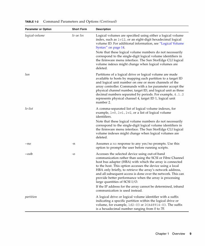
logical-volume lv or lvs Logical volumes are specified using either a logical volume index, such as lv12, or an eight-digit hexadecimal logical volume ID. For additional information, see “Logical Volume Syntax” on page 14.Note that these logical volume numbers do not necessarily correspond to the single-digit logical volume identifiers in the firmware menu interface. The Sun StorEdge CLI logical volume indexes might change when logical volumes are deleted.
lun Partitions of a logical drive or logical volume are made available to hosts by mapping each partition to a target ID and logical unit number on one or more channels of the array controller. Commands with a lun parameter accept the physical channel number, target ID, and logical unit as three decimal numbers separated by periods. For example, 4.1.2 represents physical channel 4, target ID 1, logical unit number 2.
lv-list A comma-separated list of logical volume indexes, for example, lv0,lv1,lv2, or a list of logical volume identifiers. Note that these logical volume numbers do not necessarily correspond to the single-digit logical volume identifiers in the firmware menu interface. The Sun StorEdge CLI logical volume indexes might change when logical volumes are deleted.
--no -n Assumes a no response to any yes/no prompts. Use this option to prompt the user before running scripts.
--oob -o Accesses the selected device using out-of-band communication rather than using the SCSI or Fibre Channel host bus adapter (HBA) with which the array is connected to the host. This option accesses the device using a local HBA only briefly, to retrieve the array’s network address, and all subsequent access is done over the network. This can provide better performance when the array is processing large quantities of SCSI I/O.If the IP address for the array cannot be determined, inband communication is used instead.
partition A logical drive or logical volume identifier with a suffix indicating a specific partition within the logical drive or volume, for example, ld2-03 or 2CA48914-03. The suffix is a hexadecimal number ranging from 0 to 7F.
TABLE 1-2 Command Parameters and Options (Continued)
Parameter or Option Short Form Description
Chapter 1 Overview 9

Device Names for Inband CommunicationFor inband communication, device names include one of the following:
■ Native SCSI or FC disk device file names■ Native device file names with the directory names and partitions removed
For systems using the Solaris operating system, the device name is typically specified as:
In the preceding device name code:
X = controller number
Y = SCSI target number
Z = logical unit number
s2 = slice 2 of the (logical) disk. Usually, slice 2 is specified when identifying a disk for administrative purposes, but any slice number between 0 and 7 (if the slice exists) works.
An example of the device name in Solaris is:
--password password -w password Specifies the password assigned to the array controller. The user must supply the correct password when issuing potentially dangerous commands to the array over a network connection. For security reasons, it is preferable to supply this password using the Sun StorEdge CLI password command, or enter the password interactively when prompted for it. No password is required for commands which do not modify the state of the controller, or commands issued using the inband communication mode.
target-list A comma-separated list of SCSI target ID numbers.
--version -v Displays the version number of the Sun StorEdge CLI and exits without processing any commands.
--yes -y Assumes a yes response to any yes/no prompts. Use this option to run scripts without prompting the user.
/dev/rdsk/cXtYdZs2
/dev/rdsk/c2t0d0
TABLE 1-2 Command Parameters and Options (Continued)
Parameter or Option Short Form Description
10 Sun StorEdge 3000 Family CLI 2.4 User’s Guide • March 2007

To access a JBOD enclosure services device using Solaris, specify the device name as shown in the following example, or use the --disk option and specify the name of a disk device within the enclosure.
For Windows operating systems, the device name is specified using the Windows internal device name for the physical device, where N corresponds to the disk number displayed in the Disk Administrator.
For example:
Note – If no device is specified on the command line, and more than one array is connected to the host, a menu of devices is presented with one device file name for each array. If there is only one Sun StorEdge 3000 family array device connected to the host, that device is selected automatically.
Note – If inband management access has been disabled by Sun StorEdge CLI—the firmware application—or Sun StorEdge Configuration Service, and a user attempts to use inband management, the message “RAID controller not responding” displays when a command is run. If this occurs, use out-of-band management to access Sun StorEdge CLI. For details, see “Device Names for Out-of-Band Communication” on page 11.
Device Names for Out-of-Band CommunicationTo access a RAID array using its out-of-band network interface rather than using the SCSI or FC host bus adapter (HBA) with which the array is connected to the host, specify the --oob option. This option accesses the device using a local HBA only briefly, to retrieve the array’s network address, and all subsequent access is done over the network. Out-of-band communication is useful when heavy SCSI I/O makes inband access slow. It can also be used when the host has no path to the primary controller, but can still retrieve the IP address of the array from a logical unit number (LUN) mapped from the secondary controller.
/dev/es/sesn
\\.\PhysicalDriveN
PhysicalDrive3
Chapter 1 Overview 11

Alternately, if the host on which the Sun StorEdge CLI is running is not connected to the array with a SCSI or FC HBA, a URL can be specified to indicate that the Sun StorEdge CLI should connect to the remote array over the network.
In out-of-band management, the device name is typically specified as a URL in the format:
Disk Device SyntaxA physical disk attached to the array can be identified with any of the following:
[se3000://] hostname-or-address[:port]
TABLE 1-3 Out-of-Band Device Name Syntax
Syntax Description
[se3000://] Optionally, use this prefix to ensure that the string that follows is interpreted only as a host name and not as a device name.
hostname-or-address Specify a host name or the IP address for the host of the primary agent.
port Optionally, specify the TCP/IP port number to use. The default value, 58632, is the only supported value.
TABLE 1-4 Disk Device Syntax
Syntax Description
ch.id Dotted-decimal format where ch is physical device channel and id is the SCSI ID of the device.
ch.m-n Where ch is physical device channel and m to n represents a contiguous range of IDs on the same channel.
sdn or c<X>t<Y>d<Z>
JBOD LVD disks only. Specify a disk device using a Solaris or SPARC device name such as sd31 or c1t0d0 when a JBOD chassis is selected.
12 Sun StorEdge 3000 Family CLI 2.4 User’s Guide • March 2007

Logical Drive SyntaxLogical drives can be specified by one of the following alphanumeric strings:
■ an eight-digit hexadecimal logical drive identifier.
■ a logical drive index composed of the prefix “ld” followed by a temporary decimal ordinal number ranging from 0 to n-1, where n is the number of logical drives configured on the array.
Note – Logical drive indexes can change whenever a logical drive is deleted, while a logical drive identifier never changes over the life of the logical drive.
The logical drive index number referenced with each logical drive is dynamic; it might change when logical drives are created or deleted. The index number is used strictly as a placeholder that enables you to visually keep track of logical drives. For example, if four logical drives exist, and LD2 is deleted, the existing LD3 dynamically changes to LD2, and LD4 changes to LD3. Only the LD index number changes; all LUN mapping and data on the logical drives remains unchanged. Care must be taken not to assume that a logical drive keeps the same logical drive index after creating or deleting any logical drive or rebooting the array controller.
Caution – Any time logical drives are created or deleted, the numbering of logical drive indexes might change. After creating or deleting logical drives, issue a show logical-drive command to view an updated list of logical drive indexes. Or, use logical drive IDs, which do not change over the lifetime of the logical drive, rather than logical drive indexes.
Note – In contrast, in the firmware application, the LG number on the View and Edit Logical Drives menu is not dynamic. After a logical drive is deleted, you see an empty placeholder.
Some commands accept a list of logical drives, or LD-list. This list is constructed by concatenating one or more logical drive identifiers or indexes as shown in the following examples.
This example lists logical drives using the local drive identifier.
0043BF50,05CC1F19,025E42E1
Chapter 1 Overview 13

This example lists logical drives using the index number.
Note – Do not include spaces before or after the commas when specifying a logical drive list.
Logical Volume SyntaxLogical volumes are specified by one of the following alphanumeric strings:
■ an eight-digit hexadecimal logical volume identifier.
■ a logical volume index composed of the prefix “lv” followed by a temporary decimal ordinal number ranging from 0 to n-1, where n is the number of logical volumes configured on the array.
Note – Logical volume indexes can change whenever a logical volume is deleted, while a logical volume identifier never changes over the life of the logical volume.
The logical volume index number referenced with each logical volume is dynamic; it might change when logical volumes are created or deleted. The index number is used strictly as a placeholder that enables you to visually keep track of logical volumes. For example, if four logical volumes exist, and LV2 is deleted, the existing LV3 dynamically changes to LV2, and LV4 changes to LV3. Only the LV index number changes; all LUN mapping and data on the logical volume remains unchanged. Care must be taken not to assume that a logical volume keeps the same logical volume index after creating or deleting any logical volume or rebooting the array controller.
A list of logical volumes identifiers or indexes can be specified by concatenating one or more logical drive identifiers or logical volume indexes, separating them with commas.
Caution – Any time logical volumes are created or deleted, the numbering of logical volume indexes might change. After creating or deleting logical volumes, issue a show logical-volumes command to view an updated list of logical volume indexes. Or, use logical volume IDs, which do not change over the lifetime of the logical volume, rather than logical volume indexes.
ld0,ld1,ld2
14 Sun StorEdge 3000 Family CLI 2.4 User’s Guide • March 2007

Note – In contrast, in the firmware application, the LG number on the View and Edit Logical Drives menu is not dynamic. After a logical volume is deleted, you see an empty placeholder.
This example lists logical volumes using the local volume identifier.
This example lists logical volumes using the local volume index number.
Device CapacityIn the Sun StorEdge CLI, all device capacity is displayed in powers of 1024.
1 Kbyte = 1024 bytes
1 Mbyte = 1024 Kbyte = 1,048,576 bytes
1 Gbyte = 1024 Mbyte = 1,073,741,824 bytes
1 Tbyte = 1024 Gbyte = 1,099,511,627,776 bytes
52AD5DEB,472C1397,E2054317
lv0,lv1,lv2
Chapter 1 Overview 15

16 Sun StorEdge 3000 Family CLI 2.4 User’s Guide • March 2007

CHAPTER 2
System Function Commands
This chapter provides the available system function commands with sample code. Topics covered in this chapter include:
■ “Basic Commands” on page 18■ “Network Commands” on page 21■ “Component Status Commands” on page 31■ “Configuration Commands” on page 49■ “Event Message Commands” on page 63
Note – To prevent unauthorized access to administrative functions of the RAID controller, the Sun StorEdge CLI requires superuser or system administrator privileges for inband access, and uses the controller password to authorize users of the out-of-band interface.
Note – If no command is entered on the command line, the Sun StorEdge CLI enters an interactive mode, prompting you to enter commands until the quit command is entered. All commands operate on the currently selected device.
17

Basic CommandsThe following commands are explained in this section:
■ about■ exit■ help■ quit■ select■ version
about
Description
The about command displays version, copyright, build, and operating system information.
Syntax
Examples
The following example shows the about text for the Sun StorEdge CLI.
exit
Description
The exit command exits the interactive mode. You can also use the quit command to exit the Sun StorEdge CLI.
about
sccli> aboutSun StorEdge 3000 Family CLICopyright 2002-2005 Dot Hill Systems Corporation.All rights reserved. Use is subject to license terms.sccli version 2.1.0built 2005.04.30.21.02build 11 for solaris-sparc
18 Sun StorEdge 3000 Family CLI 2.4 User’s Guide • March 2007

Syntax
help
Description
The help command displays a short summary of the available commands.
Syntax
If no command is specified, basic usage information is displayed.
Examples
The following example shows the help text for the show channels command.
quit
Description
The quit command exits the interactive mode. You can also use the exit command to exit the Sun StorEdge CLI.
Syntax
exit
help [command]
sccli> help show channels show channels display channel configuration
quit
Chapter 2 System Function Commands 19

select
Description
The select command selects a new device to which subsequent commands are issued. If no device is specified, and more than one choice exists, a menu of choices is displayed. This command should not be used on the command line because a select command is automatically executed if no device name is specified.
Syntax
Examples
The following example selects an out-of-band FC device.
The following example selects an inband SCSI device.
version
Description
The version command displays the version number of the Sun StorEdge CLI.
Syntax
Examples
In the following example, version 2.1.0 is displayed.
select device
sccli> select 199.249.246.28sccli: selecting se3000://199.249.246.28:58632[SUN StorEdge 3510 SN#000187]
sccli> select c15t0d0sccli: selected /dev/rdsk/c0t5d0s2 [SUN StorEdge 3310 SN#00028E]
version
20 Sun StorEdge 3000 Family CLI 2.4 User’s Guide • March 2007

Network CommandsThe following commands are explained in this section:
■ configure network-interface■ create host-wwn-name■ delete host-wwn-name■ set protocol■ show host-wwn-names■ show ip-address■ show network-parameters■ show port-wwn■ show protocol■ show rs232-configuration
configure network-interface
Description
The configure network-interface command configures the local area network (LAN) interface, enabling the telnet, File Transfer Protocol (FTP), Simple Network Management Protocol (SNMP), and out-of-band management functions.
Note – If you assign an IP address to an array to manage it out-of-band, for security reasons consider using an IP address on a private network rather than a publicly routable network. Using the controller firmware to set a password for the controller limits unauthorized access to the array. Changing the firmware’s Network Protocol Support settings can provide further security by disabling the ability to remotely connect to the array using individual protocols such as HTTP, HTTPS, telnet, FTP, and SSH. Refer to the “Communication Parameters” section of the Sun StorEdge 3000 Family RAID Firmware User’s Guide for more information.
# sccli versionsccli: selected se3000://199.249.246.28:58632[SUN StorEdge 3510 SN#000187]sccli version 2.1.0
Chapter 2 System Function Commands 21

Syntax
For dynamic addressing, use the following syntax.
For static addressing, use the following syntax.
Arguments
The following dynamic options are accepted.
Note – The rarp and dhcp options can be combined to specify that the controller try the protocols in the listed order.
Note – All LAN parameters must be specified on the same command line.
Alternately, if none of the dynamic options are specified on the same command line, a static IP address can be specified along with optional netmask and default gateway parameters.
configure network-interface lan0 [rarp| dhcp]
configure network-interface lan0 [ip-address ip-address | netmask netmask-ip | gateway gateway-ip]
TABLE 2-1 Dynamic Options for configure network-interface
Argument Description
rarp Specify whether the Reverse Address Resolution Protocol (RARP) is used to establish an IP address.
dhcp Specify whether the Dynamic Host Configuration Protocol (DHCP) is used to obtain an IP address.
TABLE 2-2 Static Options for configure network-interface
Argument Description
ip-address n.n.n.n The IP address of the array.
netmask m.m.m.m The netmask, in dotted-decimal format; for example, 255.255.255.0
gateway g.g.g.g The IP address of a default router.
22 Sun StorEdge 3000 Family CLI 2.4 User’s Guide • March 2007

Examples
The following example configures the controller IP address as 192.168.0.10, netmask as 255.255.255.0, and gateway as 192.168.0.1.
The following example specifies that the DHCP protocol be used to establish an IP address.
create host-wwn-name
Description
Sun StorEdge 3000 family FC and SATA devices only. The create host-wwn-name command creates a list of Host ID/worldwide name (WWN) entries to associate a symbolic name with a host worldwide port name (WWPN). This enables the user to use the symbolic name instead of the numeric WWPN when creating host LUN filters. To review the available WWPN values, run the show port-wwn command. For details, see “show port-wwn” on page 29.
Note – A maximum of 64 host WWN entries can be created.
Syntax
# sccli c2t0d0 configure network-interface lan0 ip 192.168.0.10 netmask 255.255.255.0 gateway 192.168.0.1
# sccli c2t0d0 configure network-interface lan0 dhcp
create host-wwn-name wwn name [position]
Chapter 2 System Function Commands 23

Arguments
Examples
The following example creates the alias sun-hba-1 for the HBA WWPN value 210000e08b095562.
To see the existing WWNs, use the show host-wwn-names command. For details, see “show host-wwn-names” on page 27.
delete host-wwn-name
Description
Sun StorEdge 3000 family FC and SATA devices only. The delete host-wwn-name command deletes a Host ID/worldwide name (WWN) entry.
Syntax
Note – Names that contain special characters, such as spaces, must be enclosed in double quotation marks.
TABLE 2-3 Arguments for create host-wwn-name
Argument Description
wwn Specify a WWPN corresponding to a host bus adapter, expressed as a 16-digit hexadecimal number.
name Specify a symbolic name for the host bus adapter. Names that contain special characters, such as spaces, must be enclosed in double quotation marks.
[position] Specify a number representing the position in the list of names where this name will appear. To add the WWN to the top of the WWN list, specify head. To add the WWN to the bottom of the WWN list, specify tail.
# sccli c2t0d0 create host-wwn-name 210000e08b095562 sun-hba-1
delete host-wwn-name [name | wwn]
24 Sun StorEdge 3000 Family CLI 2.4 User’s Guide • March 2007

Examples
The following example deletes the alias test name 2.
set protocol
Description
The set protocol command enables or disables the specified network protocol and sets the telnet inactivity timeout value. For security reasons, you might want to disable the network protocols that you do not want to support. This limits the ways security can be breached.
Syntax
Arguments
Note – The PriAgentAll protocol must remain enabled for Sun StorEdge Configuration Service and Sun StorEdge CLI to receive information from the controller firmware. Do not disable this protocol.
sccli> delete host-wwn-name “test name 2”
set protocol {protocol-name {enabled | disabled} | telnet-inactivity-timeout s}
Chapter 2 System Function Commands 25

Examples
The following example sets the telnet inactivity time period to 60 seconds.
The following example disables FTP access.
TABLE 2-4 Arguments for set protocol
Argument Description
protocol-name {enabled | disabled}
Specify the protocol name and enabled or disabled to control the protocols that can be used to access the Sun StorEdge CLI. For instance, to prohibit data access through a protocol, specify the protocol name and disabled. The supported protocol values include:• TELNET – Telnet access to the IP address (enabled by default).• HTTP – Hypertext Transport Protocol (enabled by default).• HTTPS – Hypertext Transport Protocol Secure (disabled by
default).• FTP – File Transfer Protocol (enabled by default).• SSH – Secure Socket Handling (disabled by default).• PriAgentAll – Controller internal communication protocol
(enabled by default).• SNMP – Simple Network Management Protocol (disabled by
default). SNMP might be used to communicate with external management software.
• DHCP – Dynamic Host Configuration Protocol (enabled by default). DHCP is used in some networks to dynamically assign IP addresses to systems on the network.
• Ping – Ping enables hosts in the network to determine if an array is online (enabled by default).
Valid values: enabled, disabled.
telnet-inactivity-timeout s
Specify the amount of time before the telnet connection times out. Valid values: 0 (disabled), 60s, 120s, 300s, 600s, 1200s, 1500s, 1800s, 2700s.
# sccli c2t0d0 set protocol telnet-inactivity-timeout 60s
# sccli c2t0d0 set protocol ftp disabled
26 Sun StorEdge 3000 Family CLI 2.4 User’s Guide • March 2007

show host-wwn-names
Description
Sun StorEdge 3000 family FC and SATA devices only. The show host-wwn-names command displays all registered host bus adapter (HBA) worldwide name (WWN) entries in the controller for host channels.
Note – A maximum of 64 host WWN entries can be created.
Syntax
Arguments
Examples
The following example shows all host WWN entries for the specified device.
If no host WWN entries are defined, a message is displayed onscreen, but it is not considered an error. For details on defining host WWN entries, see “create host-wwn-name” on page 23.
show host-wwn-names
TABLE 2-5 Arguments for show host-wwn-names
Argument Description
[name | wwn] Specify the host name or WWN.
# sccli c2t0d0 show host-wwn-names Host-ID/WWN Name --------------------------------------210000e08b095562 sun-hba-1210100e08b295562 sun-hba-2
Chapter 2 System Function Commands 27

show ip-address
Description
The show ip-address command displays the IP address of the array controller.
Note – Before running this command, make sure the network parameters on the controller are set.
Syntax
Examples
The following example shows the IP address for device c2t0d0.
show network-parameters
Description
The show network-parameters command displays the IP address, netmask, and default router address of the network management port.
Syntax
show ip-address
# sccli c2t0d0 show ip-address206.1.111.11
show network-parameters
28 Sun StorEdge 3000 Family CLI 2.4 User’s Guide • March 2007

Examples
The following example shows the network parameters for the network management port.
show port-wwn
Description
Sun StorEdge 3000 family FC and SATA devices only. The show port-wwn command displays the worldwide name (WWN) entries for the FC host channels.
Note – A maximum of 64 host WWN entries can be created.
Syntax
Examples
The following example shows the worldwide port name (WWPN) entries for the FC host channels.
sccli> show network-parameters ip-address: 206.235.238.223 netmask: 255.255.255.0 gateway: 0.0.0.0 mode: static
show port-wwn
sccli> show port-wwnCh Id WWPN------------------------- 0 40 216000C0FF800238 0 41 216000C0FF900238 1 43 226000C0FFB00238 1 42 226000C0FFA00238 4 44 256000C0FFC00238 4 45 256000C0FFD00238 5 47 266000C0FFF00238 5 46 266000C0FFE00238
Chapter 2 System Function Commands 29

show protocol
Description
The show protocol command displays all possible network protocols supported by the controller and protocol parameters including the Telnet inactivity timeout value. To enable and disable network protocols, see “set protocol” on page 25.
Syntax
Examples
The following example shows all network protocols for the specified device and shows that the telnet connection does not time out if it is not being used.
Returned Values
The returned protocol values include:
■ telnet – Telnet access to the IP address (enabled by default) and the Inactivity-timeout parameter which indicates the amount of time before the Telnet connection times out.
■ HTTP – Hypertext Transport Protocol (disabled by default).
■ HTTPS – Hypertext Transport Protocol Secure (disabled by default).
■ FTP – File Transfer Protocol (disabled by default).
■ SSH – Secure Socket Handling (disabled by default).
■ PriAgentAll – Controller internal communication protocol (enabled by default).
show protocol
sccli> show protocol Identifier Status Port Parameters -------------------------------------- telnet enabled 23 inactivity-timeout=disabled http enabled 80 n/a https enabled 443 n/a ftp enabled 21 n/a ssh enabled 22 n/a priagentall enabled 1 n/a snmp enabled 161 n/a dhcp enabled 68 n/a ping enabled n/a n/a
30 Sun StorEdge 3000 Family CLI 2.4 User’s Guide • March 2007

■ SNMP – Simple Network Management Protocol (enabled by default). SNMP might be used to communicate with external management software.
■ DHCP – Dynamic Host Configuration Protocol (enabled by default). DHCP is used in some networks to dynamically assign IP addresses to systems on the network.
■ ping – Ping enables hosts in the network to determine if an array is online (enabled by default).
show rs232-configuration
Description
The show rs232-configuration command displays the RS-232 connection configuration. Returned values include the port number and current baud rate. In a redundant-controller configuration, the COM port rate is always the same for both ports. Valid rates include: 2400, 4800, 9600, 19200, 38400, and 115200.
Syntax
Examples
The following example shows the baud-rate is set to 38400 bps for COM1 and COM2.
Component Status CommandsThe following commands are explained in this section:
■ set auto-write-through-trigger■ show access-mode■ show auto-write-through-trigger■ show battery-status■ show enclosure-status
show rs232-configuration
sccli> show rs232-configuration COM1 speed: 38400bps COM2 speed: 38400bps
Chapter 2 System Function Commands 31

■ show frus■ show peripheral-device-status
For details on displaying all the components for an array, see “show configuration” on page 57.
set auto-write-through-trigger
Description
Use the set auto-write-through-trigger command to configure the array to dynamically switch from write-back cache to write-through cache, or to shut down the controller, if a specified event occurs. For details on setting the write policy, see “set cache-parameters” on page 73.
Syntax
Arguments
set auto-write-through-trigger param value
TABLE 2-6 Arguments for set auto-write-through-trigger
Argument Description
controller-failure
If the cache setting is set to write-back, specify whether the cache setting automatically defaults to write-through cache when a controller event trigger operation, such as a controller failure, occurs. Valid values: enabled, disabled.
battery-backup-failure
If the cache setting is set to write-back, specify whether the cache setting automatically defaults to write-through cache when a battery backup event trigger operation, such as low voltage on a battery backup device, occurs. Valid values: enabled, disabled.
ac-power-loss If the cache setting is set to write-back, specify whether the cache setting automatically defaults to write-through cache when a power loss event trigger operation, such as a power failure, occurs. Valid values: enabled, disabled.
32 Sun StorEdge 3000 Family CLI 2.4 User’s Guide • March 2007

Examples
The following example sets the temperature threshold time period to two minutes.
The following example disables the automatic write policy change on controller failure.
show access-mode
Description
The show access-mode command displays whether the communication mode being used to manage the device uses data channels (inband) or an Ethernet connection (out-of-band). Returned values include inband and out-of-band.
Note – If inband management access has been disabled by Sun StorEdge CLI—the firmware application—or Sun StorEdge Configuration Service, and a user attempts to use inband management, the message “RAID controller not responding” displays when a command is run. If this occurs, use out-of-band management to access Sun StorEdge CLI. For details, see “Device Names for Out-of-Band Communication” on page 11.
power-supply-failure
If the cache setting is set to write-back, specify whether the cache setting automatically defaults to write-through cache when a power supply event trigger operation, such as a power supply failure, occurs. Valid values: enabled, disabled.
fan-failure If the cache setting is set to write-back, specify whether the cache setting automatically defaults to write-through cache when a fan event trigger operation, such as a fan failure, occurs. Valid values: enabled, disabled.
temperature-exceeded-delay
Specify whether to force a controller shutdown if a temperature is detected that exceeds system threshold limits. Adjust this setting to shut down the controller as soon as the temperature limit is exceeded, or after a configurable delay. Valid values: enabled, disabled, 2min, 5min, 10min, 20min, 30min, 45min, 1hour.
sccli> set auto-write-through-trigger temperature-exceeded-delay 2min
sccli> set auto-write-through-trigger controller-failure disabled
TABLE 2-6 Arguments for set auto-write-through-trigger (Continued)
Argument Description
Chapter 2 System Function Commands 33

Syntax
Examples
The following example shows the Sun StorEdge CLI communication mode is inband.
show auto-write-through-trigger
Description
The show auto-write-through-trigger command displays the controller event trigger configuration including whether the array dynamically switches from write-back cache to write-through cache, or shuts down the controller, if a specified event occurs. The specified events include fan failure, power supply failure, battery back-up failure, AC power loss, and temperature that exceeds system threshold limits.
Syntax
Examples
The following example shows the event trigger information for a Sun StorEdge 3510 FC array.
show access-mode
sccli> show access-mode access-mode: inband
show auto-write-through-trigger
sccli> show auto-write-through-trigger controller-failure: enabled battery-backup-failure: enabled ups-ac-power-loss: disabled power-supply-failure: enabled fan-failure: enabled temperature-exceeded-delay: enabled
34 Sun StorEdge 3000 Family CLI 2.4 User’s Guide • March 2007

Returned Values
The returned values are described in the following table.
show battery-status
Description
Sun StorEdge 3000 family FC and SATA arrays only. The show battery-status command displays the expiration and hardware status of the battery modules, which preserve the contents of the write cache in each RAID controller. For redundant controllers, status for both batteries is shown.
If you run the show battery-status command and the battery in-service date is not set, run the show battery-status -u command. Early model battery boards were not programmed with an in-service date. The show battery-status -u command sets the in-service date to the battery board manufacturing date and prompts the user to verify the date. For details on replacing the battery, refer to the Sun StorEdge 3000 Family FRU Installation Guide.
Note – To successfully execute scripts using the Sun StorEdge CLI, the battery in-service date must be set. Newer battery boards are programmed with the in-service date.
If the battery type is an early board module (FRU ID 370-5545 REVB), then battery expiration monitoring is not supported. In this case, a message displays, “battery board type is not supported.” If your configuration requires the battery expiration feature, consult your sales representative to obtain a new battery.
TABLE 2-7 Output for show auto-write-through-trigger
Field Description
controller-failure Controller failure event trigger status.
battery-backup-failure Battery backup unit has failed or is not fully charged.
ups-ac-power-loss UPS AC power loss.
power-supply-failure Power supply failure.
fan-failure Fan failure.
temperature-exceeded-delay Number of seconds delay before controller shutdown after exceeding the temperature threshold Valid values: enabled, disabled, 2min, 5min, 10min, 20min, 30min, 45min, 1hour.
Chapter 2 System Function Commands 35
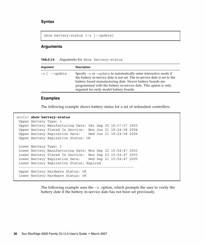
Syntax
Arguments
Examples
The following example shows battery status for a set of redundant controllers.
The following example uses the -u option, which prompts the user to verify the battery date if the battery in-service date has not been set previously.
show battery-status [-u |--update]
TABLE 2-8 Arguments for show battery-status
Argument Description
-u | --update Specify -u or --update to automatically enter interactive mode if the battery in-service date is not set. The in-service date is set to the battery board manufacturing date. Newer battery boards are programmed with the battery in-service date. This option is only required for early model battery boards.
sccli> show battery-status Upper Battery Type: 1 Upper Battery Manufacturing Date: Sat Sep 20 16:17:57 2003 Upper Battery Placed In Service: Mon Jun 21 18:24:58 2004 Upper Battery Expiration Date: Wed Jun 21 18:24:58 2006 Upper Battery Expiration Status: OK
Lower Battery Type: 1 Lower Battery Manufacturing Date: Mon Sep 22 15:54:47 2003 Lower Battery Placed In Service: Mon Sep 22 15:54:47 2003 Lower Battery Expiration Date: Wed Sep 21 15:54:47 2005 Lower Battery Expiration Status: Expired -------------------------------------------------------- Upper Battery Hardware Status: OK Lower Battery Hardware Status: OK
36 Sun StorEdge 3000 Family CLI 2.4 User’s Guide • March 2007

Returned Values
The returned expiration and hardware status values for the show battery-status command are described in the tables below.
sccli> show battery-status -u Upper Battery Type: 1 Upper Battery Manufacturing Date: Mon Feb 2 08:00:00 2004 Upper Battery Placed In Service: Wed Aug 11 20:18:02 2004 Upper Battery Expiration Date: Fri Aug 11 20:18:02 2006 Upper Battery Expiration Status: OK
Lower Battery Type: 1 Lower Battery Manufacturing Date: Tue Mar 30 14:32:26 2004 Lower Battery Placed In Service: Wed Sep 29 21:04:39 2004 Lower Battery Expiration Date: Fri Sep 29 21:04:39 2006 Lower Battery Expiration Status: OK -------------------------------------------------------- Upper Battery Hardware Status: OK Lower Battery Hardware Status: OK
TABLE 2-9 Battery expiration status values for show battery status
Value Description
OK Battery is neither near nor at expiration
Warning Three weeks or less to battery expiration
Expired Battery expired
TABLE 2-10 Battery hardware status values for show battery status
Value Description
OK Battery fully charged and functioning
Charging Battery slightly drained and charging
Critical Battery almost drained and charging
Missing Battery not installed
BAD Battery completely drained or not functioning
Chapter 2 System Function Commands 37

show enclosure-status
Description
The show enclosure-status command shows the status for all chassis components. If the selected device is a RAID subsystem consisting of more than one chassis, status displays for each chassis in the system. For details on the controller environmental sensor status, see “show peripheral-device-status” on page 47.
Sun StorEdge 3000 family SCSI arrays display the status for the:
■ SCSI Accessed Fault-Tolerant Enclosure (SAF-TE) revision number and status information
■ fan
■ power supply
■ temperature sensor
■ drive slot
Note – In split-bus configurations on Sun StorEdge 3000 SCSI devices, half the drives display a status of Unknown. The drives are present, but because of a SAF-TE design limitation, the information does not display.
Sun StorEdge 3510 FC arrays and Sun StorEdge 3511 SATA arrays display the status for the:
■ SCSI Enclosure Services (SES) revision number and status information
■ fan
■ power supply
■ temperature sensor
■ drive slot
■ voltage sensors – 16 sensors display for SATA devices and 12 sensors display for FC devices
Note – Sun StorEdge 3000 family FC and SATA enclosures contain two SES processors in a dual-controller array, and there can be more than one enclosure in a RAID subsystem.
Syntax
show enclosure-status
38 Sun StorEdge 3000 Family CLI 2.4 User’s Guide • March 2007

Examples
The following example shows the enclosure status for a Sun StorEdge 3310 SCSI device.
Note – The Enclosure SCSI channel type values include single-bus and split-bus. Throughout the documentation and the Sun StorEdge CLI, the term “split-bus” is interchangeable with the term “dual-bus.” For details on configuring an array, refer to the Sun StorEdge 3000 Family RAID Firmware User’s Guide for your array.
sccli> show enclosure-statusCh Id Chassis Vendor Product ID Rev Package Status---------------------------------------------------------------- 0 14 002A4C SUN StorEdge 3310 A 1170 1170 OK
Enclosure Component Status: Type Unit Status FRU P/N FRU S/N Add'l Data---------------------------------------------------------------- Fan 0 OK 370-5398 016626 -- Fan 1 OK 370-5398 016625 -- PS 0 OK 370-5398 016626 -- PS 1 OK 370-5398 016625 -- Temp 0 OK 370-5524 002A4C temp=25 Temp 1 OK 370-5524 002A4C temp=27 Temp 2 OK 370-5398 016626 temp=26 Temp 3 OK 370-5394 013924 temp=30 Temp 4 OK 370-5394 013919 temp=28 Temp 5 OK 370-5524 002A4C temp=28 Temp 6 OK 370-5398 016625 temp=25 EMU 0 OK 370-5394 013924 EMU 1 OK 370-5394 013919 DiskSlot 0 Unknown 370-5524 002A4C addr=0,led=off DiskSlot 1 Unknown 370-5524 002A4C addr=1,led=off DiskSlot 2 Unknown 370-5524 002A4C addr=2,led=off DiskSlot 3 Unknown 370-5524 002A4C addr=3,led=off DiskSlot 4 Unknown 370-5524 002A4C addr=4,led=off DiskSlot 5 Unknown 370-5524 002A4C addr=5,led=off DiskSlot 6 OK 370-5524 002A4C addr=0,led=off DiskSlot 7 OK 370-5524 002A4C addr=1,led=off DiskSlot 8 OK 370-5524 002A4C addr=2,led=off DiskSlot 9 OK 370-5524 002A4C addr=3,led=off DiskSlot 10 OK 370-5524 002A4C addr=4,led=off DiskSlot 11 OK 370-5524 002A4C addr=5,led=off
Enclosure SCSI Channel Type: split-bus
Chapter 2 System Function Commands 39
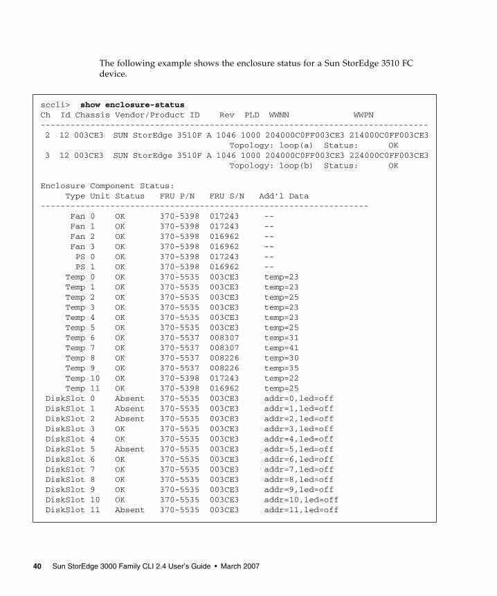
The following example shows the enclosure status for a Sun StorEdge 3510 FC device.
sccli> show enclosure-statusCh Id Chassis Vendor/Product ID Rev PLD WWNN WWPN------------------------------------------------------------------------------ 2 12 003CE3 SUN StorEdge 3510F A 1046 1000 204000C0FF003CE3 214000C0FF003CE3 Topology: loop(a) Status: OK 3 12 003CE3 SUN StorEdge 3510F A 1046 1000 204000C0FF003CE3 224000C0FF003CE3 Topology: loop(b) Status: OK
Enclosure Component Status: Type Unit Status FRU P/N FRU S/N Add'l Data------------------------------------------------------------------ Fan 0 OK 370-5398 017243 -- Fan 1 OK 370-5398 017243 -- Fan 2 OK 370-5398 016962 -- Fan 3 OK 370-5398 016962 -- PS 0 OK 370-5398 017243 -- PS 1 OK 370-5398 016962 -- Temp 0 OK 370-5535 003CE3 temp=23 Temp 1 OK 370-5535 003CE3 temp=23 Temp 2 OK 370-5535 003CE3 temp=25 Temp 3 OK 370-5535 003CE3 temp=23 Temp 4 OK 370-5535 003CE3 temp=23 Temp 5 OK 370-5535 003CE3 temp=25 Temp 6 OK 370-5537 008307 temp=31 Temp 7 OK 370-5537 008307 temp=41 Temp 8 OK 370-5537 008226 temp=30 Temp 9 OK 370-5537 008226 temp=35 Temp 10 OK 370-5398 017243 temp=22 Temp 11 OK 370-5398 016962 temp=25 DiskSlot 0 Absent 370-5535 003CE3 addr=0,led=off DiskSlot 1 Absent 370-5535 003CE3 addr=1,led=off DiskSlot 2 Absent 370-5535 003CE3 addr=2,led=off DiskSlot 3 OK 370-5535 003CE3 addr=3,led=off DiskSlot 4 OK 370-5535 003CE3 addr=4,led=off DiskSlot 5 Absent 370-5535 003CE3 addr=5,led=off DiskSlot 6 OK 370-5535 003CE3 addr=6,led=off DiskSlot 7 OK 370-5535 003CE3 addr=7,led=off DiskSlot 8 OK 370-5535 003CE3 addr=8,led=off DiskSlot 9 OK 370-5535 003CE3 addr=9,led=off DiskSlot 10 OK 370-5535 003CE3 addr=10,led=off DiskSlot 11 Absent 370-5535 003CE3 addr=11,led=off
40 Sun StorEdge 3000 Family CLI 2.4 User’s Guide • March 2007

Returned Values
The following table describes the location of the enclosure devices from the back of the Sun StorEdge 3120 SCSI array, as shown in FIGURE 2-1.
FIGURE 2-1 Sun StorEdge 3120 SCSI Array Enclosure Device Orientation
The returned values for the Sun StorEdge 3120 SCSI array are described in the following table.
TABLE 2-11 Sun StorEdge 3120 SCSI array output for show enclosure-status
Enclosure Types Description
Fan 0 Left side power supply fan
Fan 1 Right side power supply fan
PS 0 Left side power supply
PS 1 Right side power supply
Temp 0 Left drive temperature sensor
Temp 1 Center drive temperature sensor
Temp 2 Temperature sensor on left side power supply module (Power supply 0 in FIGURE 2-1)
Temp 3 Temperature sensor on left side I/O module
Temp 4 Temperature sensor on right side I/O module
Power supply 0
Power supply 1
Fan 0
Fan 1
Front of array
Left side
Right side
Chapter 2 System Function Commands 41

The following table describes the location of the enclosure devices from the back of the Sun StorEdge 3310 SCSI array, as shown in FIGURE 2-2.
FIGURE 2-2 Sun StorEdge 3310 SCSI Array and Sun StorEdge 3320 SCSI Array Enclosure Device Orientation
The returned values for Sun StorEdge 3310 SCSI arrays and Sun StorEdge 3320 SCSI arrays are described in the following table.
Temp 5 Right drive temperature sensor
Temp 6 Temperature sensor on right side power supply module (Power supply1 in FIGURE 2-1)
Disk Slot 0-3 Disk slot identifier refers to the backplane field-replaceable unit (FRU) to which disks are connected
TABLE 2-12 Output for Sun StorEdge 3310 SCSI array and Sun StorEdge 3320 SCSI array show enclosure-status
Enclosure Types Description
Fan 0 Left side power supply fan
Fan 1 Right side power supply fan
PS 0 Left side power supply
PS 1 Right side power supply
TABLE 2-11 Sun StorEdge 3120 SCSI array output for show enclosure-status
Enclosure Types Description
Front of array Right side
Left side
Fan 0 Power supply 0
Power supply 1
Fan 1
42 Sun StorEdge 3000 Family CLI 2.4 User’s Guide • March 2007

The following table describes the location of the enclosure devices from the back of the Sun StorEdge 3510 FC array and the Sun StorEdge 3511 SATA array, as shown in FIGURE 2-3.
FIGURE 2-3 Sun StorEdge 3510 FC Array and Sun StorEdge 3511 SATA Array Enclosure Device Orientation
Temp 0, 1, 5 Temperature sensor on chassis
Temp 2 Temperature sensor on left side power supply module (Power supply 0 in FIGURE 2-2)
Temp 3 Temperature sensor on left side event monitoring unit (EMU) module
Temp 4 Temperature sensor on right side EMU module
Temp 6 Temperature sensor on right side power supply module (Power supply 1 in FIGURE 2-2)
EMU 0 Left side event monitoring unit
EMU 1 Right side event monitoring unit
Disk Slot 0-11 Disk slot identifier refers to the backplane field-replaceable unit (FRU) to which disks are connected
TABLE 2-12 Output for Sun StorEdge 3310 SCSI array and Sun StorEdge 3320 SCSI array show enclosure-status (Continued)
Enclosure Types Description
Front of arrayRight side
Left side
Fan 0
Fan 1 Power supply 0
Fan 2
Fan 3
Power supply 1
Chapter 2 System Function Commands 43

The returned values for the Sun StorEdge 3510 FC array and the Sun StorEdge 3511 SATA array are described in the following table.
Note – Voltage sensors make sure that the array’s voltage is within normal ranges. To check the status and determine the location of voltage sensors, refer to the Sun StorEdge 3000 Family RAID Firmware User’s Guide.
Enclosure status values include:
TABLE 2-13 Output for Sun StorEdge 3510 FC array and Sun StorEdge 3511 SATA array show enclosure-status
Enclosure Types Description
Fan 0, 1 Left side power supply fan
Fan 2, 3 Right side power supply fan
PS 0 Left side power supply
PS 1 Right side power supply
Temp 0–5 Temperature sensor on chassis
Temp 6, 7 Temperature sensor on upper I/O module
Temp 8, 9 Temperature sensor on lower I/O module
Temp 10 Temperature sensor on left side power supply module (Power supply 0 in FIGURE 2-3)
Temp 11 Temperature sensor on right side power supply module (Power supply 1 in FIGURE 2-3)
Disk Slot 0-11 Disk slot identifier refers to the backplane field-replaceable unit (FRU) to which disks are connected
Status Description
OK This component has a status of OK.
Absent This component is absent.
Fault The component is exhibiting a fault condition.
Missing The field-replaceable unit (FRU) is missing, status cannot be determined.
Unknown This component status is not available.
44 Sun StorEdge 3000 Family CLI 2.4 User’s Guide • March 2007

show frus
Description
The show frus command displays field-replaceable unit (FRU) ID information for the RAID and any related JBODs, including dynamic FRU status information. All FRU information is retrieved from the SAF-TE device (Sun StorEdge 3000 family SCSI device), SES (Sun StorEdge 3000 family FC or SATA device), and SATA MUX board (Sun StorEdge 3511 SATA device). Use the -q option to exclude SATA MUX board information from the results, which will speed data return.
Syntax
Arguments
Examples
The following example returns all FRU information in a RAID array.
The following example returns all FRU information in a JBOD unit.
The following example shows a partial list of the FRUs in a Sun StorEdge 3310 SCSI device.
show frus [-q | --quick]
TABLE 2-14 Arguments for show frus
Argument Description
[-q | --quick] Excludes SATA MUX board information from the results, which will speed data return.
# sccli c2t0d0 show frus
# sccli /dev/es/ses2 show frus
Chapter 2 System Function Commands 45

sccli> show frus Name: PRI RAID CONTROLLER Description: SE3310 LVD RAID CTLR, 512MB MEM, BATT Part Number: 370-5403 Serial Number: 007725 Revision: 02Revision: 02 Initial Hardware Dash Level: 02 FRU Shortname: 370-5522 Manufacturing Date: Wed Jul 16 19:24:30 2003Manufacturing Location: Milpitas California, USA Manufacturer JEDEC ID: 0x0301 FRU Location: PRIMARY CONTROLLER SLOT Chassis Serial Number: 002A4C FRU Status: OK Name: SEC RAID CONTROLLER Description: SE3310 LVD RAID CTLR, 512MB MEM, BATT Part Number: 370-5403 Serial Number: 006550 Revision: 02 Manufacturing Date: Thu Jul 17 19:24:47 2003 Manufacturing Location: Milpitas California, USA Manufacturer JEDEC ID: 0x0301 FRU Location: SECONDARY CONTROLLER SLOT Chassis Serial Number: 002A4C FRU Status: OK
7 FRUs found in chassis SN#002A4C at ch 0 id 14
Name: RAID_CHASSIS_BKPLN Description: Minnow BOX, RAID, LVD, Chassis+Bkpln Part Number: 370-5524 Serial Number: 002A4C Revision: 01 Manufacturing Date: Thu Jun 26 15:15:17 2003 Manufacturing Location: Milpitas,CA,USA Manufacturer JEDEC ID: 0x0301 FRU Location: SCSI RAID MIDPLANE SLOT Chassis Serial Number: 002A4C FRU Status: OK...
46 Sun StorEdge 3000 Family CLI 2.4 User’s Guide • March 2007

Returned Values
The returned status values for the show frus command are described in the following table.
Note – In a dual controller configuration, if one controller has been removed, the surviving controller will show a Fault status because SES sensors on the removed controller are not available. The surviving controller SES will lose heartbeat to the other controller and thus detect fault status.
show peripheral-device-status
Description
The show peripheral-device-status command displays the status for all controller environmental sensors. For environmental status of the chassis (the SAF-TE or SES chassis components), see “show enclosure-status” on page 38.
The threshold ranges for peripheral devices are set using the firmware application. If a device exceeds the threshold range that was set, its status displays “Over upper threshold.” If a device does not meet the threshold range, its status displays “Under lower threshold.” For information on how to set the threshold ranges, refer to the Sun StorEdge 3000 Family RAID Firmware User’s Guide.
Syntax
TABLE 2-15 FRU Status Values
Status Description
OK All subcomponents of this FRU have a status of OK.
Fault One or more of the FRU components is exhibiting a fault condition.
Absent No FRU is located in the device.
N/A Not applicable.
show peripheral-device-status
Chapter 2 System Function Commands 47
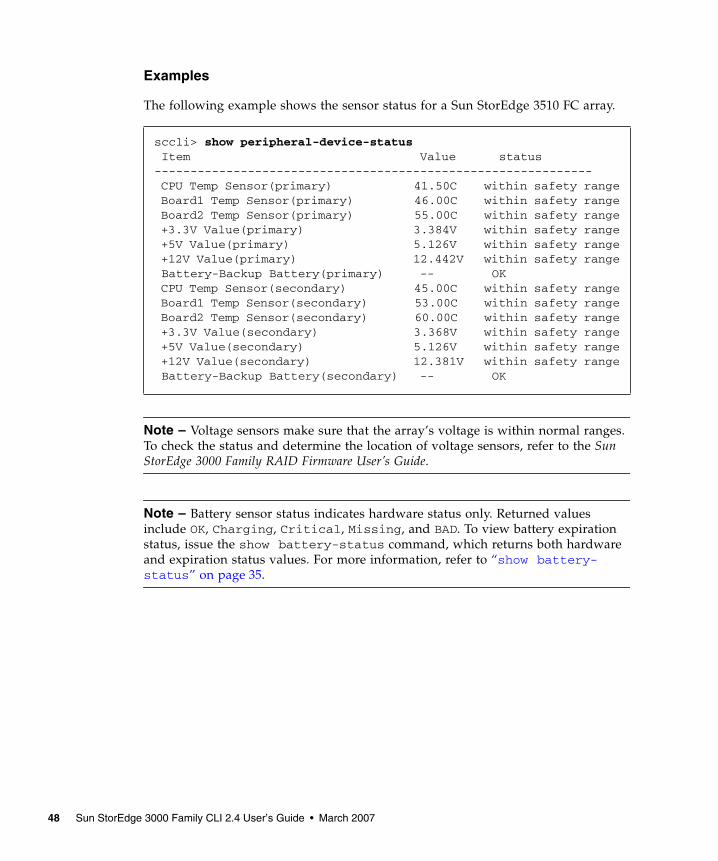
Examples
The following example shows the sensor status for a Sun StorEdge 3510 FC array.
Note – Voltage sensors make sure that the array’s voltage is within normal ranges. To check the status and determine the location of voltage sensors, refer to the Sun StorEdge 3000 Family RAID Firmware User’s Guide.
Note – Battery sensor status indicates hardware status only. Returned values include OK, Charging, Critical, Missing, and BAD. To view battery expiration status, issue the show battery-status command, which returns both hardware and expiration status values. For more information, refer to “show battery-status” on page 35.
sccli> show peripheral-device-status Item Value status------------------------------------------------------------- CPU Temp Sensor(primary) 41.50C within safety range Board1 Temp Sensor(primary) 46.00C within safety range Board2 Temp Sensor(primary) 55.00C within safety range +3.3V Value(primary) 3.384V within safety range +5V Value(primary) 5.126V within safety range +12V Value(primary) 12.442V within safety range Battery-Backup Battery(primary) -- OK CPU Temp Sensor(secondary) 45.00C within safety range Board1 Temp Sensor(secondary) 53.00C within safety range Board2 Temp Sensor(secondary) 60.00C within safety range +3.3V Value(secondary) 3.368V within safety range +5V Value(secondary) 5.126V within safety range +12V Value(secondary) 12.381V within safety range Battery-Backup Battery(secondary) -- OK
48 Sun StorEdge 3000 Family CLI 2.4 User’s Guide • March 2007

Configuration CommandsThe following commands are explained in this section:
■ download nvram■ reset nvram■ show bypass device■ show bypass RAID■ show bypass SFP■ show configuration■ show loop-map■ upload nvram
For details on uploading and downloading the controller configuration, see “download controller-configuration” on page 68 and “upload controller-configuration” on page 89.
download nvram
Description
The download nvram command restores the NVRAM configuration from an NVRAM file to the RAID controller. The binary NVRAM file contains information specific to the host device, such as channel settings, RAID controller parameters, and so on. The IP address, password, and controller name and unique ID are not downloaded from the NVRAM file to the host device since these settings differ for each controller. After the download completes, reset the controller for the NVRAM settings to take effect.
Note – The saved NVRAM file is operating system-dependent. You must download the file to the same operating system that the file is saved on. For instance, if the file is saved to the Solaris operating system, you must download it from a Solaris operating system.
Syntax
download nvram filename [-r | --reset]
Chapter 2 System Function Commands 49

Arguments
Examples
The following example downloads the NVRAM file, tmpsn2-1.nvram, and then resets the controller.
reset nvram
Description
The reset nvram command clears the NVRAM configuration memory and restores the original default settings, including all controller, host, and drive parameters. The controller unique ID is set to the chassis serial number and the controller name is not set.
Caution – This command does not restore the controller IP address, instead it configures the network for DHCP. You must have a serial connection to reset the IP address, netmask, and default gateway settings. And, the serial connection must be set to 38400. Use the RAID array’s COM port and the firmware application to restore these settings. For more information, refer to the Sun StorEdge 3000 Family RAID Firmware User’s Guide.
After issuing the reset nvram command, reset the controller and reconfigure the controller to restore any non-default configuration options for your array, such as cache write policy and LUN maps. When you run the reset nvram command, LUN maps are not restored. To review the existing LUNs before running this command, run the show lun-maps command. For details, see “show lun-maps” on page 158.
Caution – Logical drives and logical volumes are not deleted, but it is possible for them to become inaccessible after this command is run. This might result in data loss.
TABLE 2-16 Arguments for download nvram
Argument Description
filename Specify the file name for the file that you want to download.
[-r | --reset] Reset the controller after the download completes.
# sccli 192.168.0.1 download nvram /tmpsn2-1.nvram -r
50 Sun StorEdge 3000 Family CLI 2.4 User’s Guide • March 2007

Caution – All reset commands cause the array to stop responding to I/O requests from the host for a period of time. This might result in data loss unless all I/O activity is suspended by halting all applications that are accessing the array, and unmounting any file systems that are mounted from the array. In redundant-controller configurations, these commands affect all LUNs on both controllers.
Syntax
Examples
The following example shows the message prompts that are displayed when you run the reset nvram command.
show bypass device
Description
Note – This command should only be used by support personnel during troubleshooting procedures.
Sun StorEdge 3000 family FC and SATA arrays only. The show bypass device command displays the bypass status of all disks and SES devices on a specified loop.
Note – Loop A and Loop B refer to the redundant FC loops that each device is connected to. The SES device in the top slot of the chassis is connected to Loop A, which is the first drive channel. The bottom SES device is connected to Loop B, which is the second drive channel.
reset nvram
sccli> reset nvramWARNING: The configuration of the array controller will be erased.Factory default parameters will take effect at next controller reset.Logical devices may not be accessible until mappings are reconfigured.If your configuration contains more than 32 partitions, data onpartitions may no longer be accessible.Are you sure?
Chapter 2 System Function Commands 51

Sun StorEdge 3511 SATA Array
The Sun StorEdge 3511 SATA array contains a Sierra Logic SR-1216 FC-to-SATA protocol router. Unlike Sun StorEdge 3000 family FC disk drives, the SR-1216 router presents multiple FC target IDs on a single physical hardware port. Therefore, if a target ID that is presented by an SR-1216 is bypassed, the SR-1216 physical port is bypassed. This causes the IDs of all SATA drives (target IDs) that are presented by the SR-1216 port to be removed from the loop. Conversely, if a target ID that is presented by an SR-1216 is unbypassed, all SATA drives (target IDs) that are presented by the SR-1216 port are restored to the loop.
Syntax
Arguments
show bypass device ses-channel channel loop [loopa|loopb]
TABLE 2-17 Arguments for show bypass device
Argument Description
ses-channel channel
Specify the drive channel number of the FC port from which to send the command. The channel must be configured as a drive channel.Valid values: 0-5.
loop Specify the drive loop of the small form-factor (SFP) transceiver for which the bypass information is displayed. Loop a is the top slot and loop b is the bottom slot. Valid values: loopa, loopb, a, or b.
52 Sun StorEdge 3000 Family CLI 2.4 User’s Guide • March 2007

Examples
The following example is sent on channel 2 and shows the bypass information for loop A.
The following example is sent on channel 3 and shows the bypass information for loop B.
sccli> show bypass device ses-channel 2 loop loopa
CH ID TYPE ENCL LOOP BYP-STATUS ATTRIBUTES-- -- ---- ---- ---- ---------- SHF-------2 0 DISK RAID LOOP-A Unbypassed ---2 1 DISK RAID LOOP-A Bypassed S2 2 DISK RAID LOOP-A Unbypassed ---2 3 DISK RAID LOOP-A Unbypassed ---2 4 DISK RAID LOOP-A Unbypassed ---2 5 DISK RAID LOOP-A Unbypassed ---2 6 DISK RAID LOOP-A Unbypassed ---2 7 DISK RAID LOOP-A Unbypassed ---2 8 DISK RAID LOOP-A Unbypassed ---2 9 DISK RAID LOOP-A Unbypassed ---2 10 DISK RAID LOOP-A Unbypassed ---2 11 DISK RAID LOOP-A Bypassed HF2 12 SES RAID LOOP-A Unbypassed ---
sccli> show bypass device ses-channel 3 loop loopb
CH ID TYPE ENCL LOOP BYP-STATUS ATTRIBUTES-- -- ---- ---- ---- ---------- SHF-------3 0 DISK RAID LOOP-B Bypassed S3 1 DISK RAID LOOP-B Bypassed H3 2 DISK RAID LOOP-B Unbypassed ---3 3 DISK RAID LOOP-B Unbypassed ---3 4 DISK RAID LOOP-B Unbypassed ---3 5 DISK RAID LOOP-B Unbypassed ---3 6 DISK RAID LOOP-B Unbypassed ---3 7 DISK RAID LOOP-B Unbypassed ---3 8 DISK RAID LOOP-B Unbypassed ---3 9 DISK RAID LOOP-B Unbypassed ---3 10 DISK RAID LOOP-B Unbypassed ---3 11 DISK RAID LOOP-B Unbypassed ---3 12 SES RAID LOOP-B Unbypassed ---
Chapter 2 System Function Commands 53

Returned Values
If a device is bypassed, the Attributes returned values include S, F, or H.
■ An S means the device was bypassed due to a Sun StorEdge CLI command.
■ An F means a drive fault caused the bypass.
■ An H means the device was bypassed due to a hardware problem (no signal was present).
show bypass RAID
Description
Note – This command should only be used by technical support personnel during troubleshooting procedures.
Sun StorEdge 3000 family FC and SATA arrays only. The show bypass RAID command displays the hardware bypass status of the RAID controllers on Loop A and Loop B. In a redundant RAID controller system, there is a RAID controller in the top slot of the chassis and a RAID controller in the bottom slot of the chassis. Each RAID controller has a connection to Loop A and Loop B. In a normal redundant RAID controller system, the top and bottom RAID controllers indicate unbypassed status on both loops. If a RAID controller has failed due to natural causes, or has failed as a result of the fail primary or fail secondary command, the show bypass RAID command indicates that the RAID controller is bypassed.
Syntax
Examples
The following example shows the bypass status of the RAID controllers.
show bypass raid
sccli> show bypass raid
SLOT LOOP BYP-STATUS---- ---- ----------TOP LOOP-A BypassedTOP LOOP-B BypassedBOTTOM LOOP-A UnbypassedBOTTOM LOOP-B Unbypassed
54 Sun StorEdge 3000 Family CLI 2.4 User’s Guide • March 2007

show bypass SFP
Description
Note – This command should only be used by support personnel during troubleshooting procedures.
Sun StorEdge 3000 family FC and SATA arrays only. The show bypass SFP command displays the bypass status of all small form-factor (SFP) transceivers on a specified loop.
Note – Loop A and Loop B refer to the redundant FC loops that each device is connected to. The SES device in the top slot of the chassis is connected to Loop A, which is the first drive channel. The bottom SES device is connected to Loop B, which is the second drive channel.
Syntax
Arguments
show bypass sfp ses-channel channel loop [loopa|loopb]
TABLE 2-18 Arguments for show bypass SFP
Argument Description
ses-channel channel
Specify the drive channel number of the FC port from which to send the command. The channel must be configured as a drive channel.
loop Specify the drive loop of the SFP for which the bypass information is displayed. Valid values: loopa, loopb, a, or b.
Chapter 2 System Function Commands 55

Examples
The following example is sent on channel 2 and shows the bypass information for Loop A.
The following example is sent on channel 2 and shows the bypass information for a Sun StorEdge 3511 SATA array on loop A.
Returned Values
The Port returned values indicate the type of device, FC or SATA, that is attached to the loop.
■ On a Sun StorEdge 3510 FC RAID IOM board, from left to right, there are six ports: channel 0, channel 1, channel 2(3) Left, channel 2(3) Right, channel 4 and channel 5. Valid values for the Sun StorEdge 3510 FC RAID IOM board include 0, 1, 4, 5, L and R.
sccli> show bypass sfp ses-channel 2 loop loopa
PORT ENCL-ID ENCL-TYPE LOOP BYP-STATUS ATTRIBUTES---- ------- --------- ---- ---------- SH--------0 0 RAID LOOP-A Unbypassed --1 0 RAID LOOP-A Not-Installed --L 0 RAID LOOP-A Bypassed -HR 0 RAID LOOP-A Not-Installed --4 0 RAID LOOP-A Not-Installed --5 0 RAID LOOP-A Bypassed -H
sccli> show bypass sfp ses-channel 2 loop loopa
PORT ENCL-ID ENCL-TYPE LOOP BYP-STATUS ATTRIBUTES---- ------- --------- ---- ---------- SH--------0L 0 RAID LOOP-A Unbypassed --0R 0 RAID LOOP-A Unbypassed --1L 0 RAID LOOP-A Not-Installed --1R 0 RAID LOOP-A Not-Installed --2 0 RAID LOOP-A Bypassed -H3 0 RAID LOOP-A Not-Installed --4 0 RAID LOOP-A Not-Installed --5 0 RAID LOOP-A Bypassed -HAL 1 JBOD LOOP-A Unbypassed --AR 1 JBOD LOOP-A Unbypassed --BL 1 JBOD LOOP-A Unbypassed --BR 1 JBOD LOOP-A Bypassed -H
56 Sun StorEdge 3000 Family CLI 2.4 User’s Guide • March 2007

■ On a Sun StorEdge 3510 FC JBOD IOM board, from left to right, there are two ports: Left and Right. Valid values for port include L and R.
■ On a Sun StorEdge 3511 SATA RAID IOM board, from left to right, there are eight ports: channel 0 left, channel 0 right, channel 1 left, channel 1 right, channel 2, channel 3, channel 4 and channel 5. Valid values for the Sun StorEdge 3511 SATA RAID IOM board include 0L, 0R, 1L, 1R, 2, 3, 4 and 5.
■ On a Sun StorEdge 3511 SATA JBOD IOM board, from left to right, there are four ports: loop A left, loop A right, loop B left and loop B right. Valid value ports for the Sun StorEdge 3511 SATA JBOD IOM include AL, AR, BL and BR.
If a device is bypassed, the Attributes returned values include S or H.
■ An S means the device was bypassed due to a Sun StorEdge CLI command.
■ An H means the device was bypassed due to a hardware problem (no signal was present).
show configuration
Description
The show configuration command displays the array configuration including inquiry information, field-replaceable unit (FRU) information, SATA information, protocol support, automatic write-through event triggers, peripheral device status, redundancy mode, redundant-controller configuration, access mode, controller boot time and date, and the enclosure status, which includes the status for the SES or SAF-TE device and all chassis components—the fan, power supply, temperature sensor, and drive slots. The configuration can be displayed onscreen, or written to the specified file. The output is plain text by default, but XML output can be obtained by specifying the --xml option. To see a sample XML report, see “Show Configuration Command Output” on page 207.
Note – In split-bus configurations on Sun StorEdge 3000 family SCSI devices, half the drives display a status of Unknown. The drives are present, but because of a SAF-TE design limitation, the information does not display.
Note – Sun StorEdge 3000 family FC and SATA enclosures contain two SES processors in a dual-controller array, and there can be more than one enclosure in a RAID subsystem.
Syntax
show configuration [--xml | -x] [filename]
Chapter 2 System Function Commands 57

Arguments
TABLE 2-19 Arguments for show configuration
Argument Description
{--xml | -x} If the -x or --xml options are specified, XML output is generated.
filename Specify the file name for the configuration file that you want to show.
58 Sun StorEdge 3000 Family CLI 2.4 User’s Guide • March 2007

Examples
The following example shows a portion of a Sun StorEdge 3510 FC RAID configuration.
sccli> show configuration
* inquiry-data
Vendor: SUN Product: StorEdge 3510 Revision: 411G Peripheral Device Type: 0x0 NVRAM Defaults: 411G01 3510 S410F Bootrecord version: 1.31H Serial Number: 003CE3 Page 80 Serial Number: 003CE3161637C100 Page 83 Logical Unit Device ID: 600C0FF000000000003CE3161637C100 Page 83 Target Device ID: 206000C0FF003CE3 IP Address: 206.6.181.213 Page D0 Fibre Channel Address: A7 (id 40) Page D0 Node Name: 206000C0FF003CE3 Page D0 Port Name: 216000C0FF803CE3 Ethernet Address: 00:C0:FF:00:3C:E3 Device Type: Primary unique-identifier: 03CE3 controller-name: ""
* network-parameters
ip-address: 206.1.111.111 netmask: 255.255.255.0 gateway: 206.1.111.2 mode: static
* host-parameters
max-luns-per-id: 32 queue-depth: 1024 fibre-connection-mode:loop inband-mgmt-access: enabled...
Chapter 2 System Function Commands 59

The following example writes the RAID configuration information to the myconfig.xml file.
Returned Values
Configuration values in the report include inquiry data, network parameters, host parameters, drive parameters, redundant-controller configuration, redundancy mode, cache parameters, RS-232 configuration, channels, disks, logical drives, logical volumes, partitions, LUN maps, FRUs, protocols, automatic write-through event triggers, peripheral device status, enclosure status, access mode, controller date and time, disk array parameters, host WWNs (Sun StorEdge 3000 family FC and SATA devices only), port WWNs (Sun StorEdge 3000 family FC and SATA devices only), intercontroller link (Sun StorEdge 3000 family FC and SATA devices only), battery status (Sun StorEdge 3000 family FC and SATA devices only), SATA router (Sun StorEdge 3511 SATA devices only), SATA MUX (Sun StorEdge 3511 SATA devices only), SES (Sun StorEdge 3000 family FC and SATA devices only), voltage sensors (Sun StorEdge 3000 family FC and SATA devices only), and SAF-TE (Sun StorEdge 3000 family SCSI devices only).
Note – Some redundant-controller configuration values, including local/remote redundancy mode, secondary RS-232 port status, and communication channel type, are legacy parameters that are no longer used.
show loop-map
Description
Note – This command should only be used by technical support personnel during troubleshooting procedures.
Sun StorEdge 3000 family FC and SATA devices only. The show loop-map command shows the FC loop positional map for a given channel. This information shows how the FC devices are connected in the loop. The positional map displays the Arbitrated Loop Physical Address (ALPA) and the SCSI Select ID that corresponds to that ALPA. Use the positional loop map during the diagnostic process to determine which devices to selectively bypass in order to isolate faulty devices.
# sccli c2t0d0 show configuration --xml myconfig.xml
60 Sun StorEdge 3000 Family CLI 2.4 User’s Guide • March 2007

There can be two RAID controllers on each drive loop. The first device displayed in the loop map is the RAID controller that executes the diagnostics and performs the port bypass operations. Both ALPAs and SCSI Select IDs are displayed. Additional information is also displayed including device type, chassis enclosure ID, and slot number that the device resides in.
Sun StorEdge 3511 SATA Array
The Sun StorEdge 3511 SATA array contains a Sierra Logic SR-1216 FC-to-SATA protocol router. Unlike FC disk drives, the SR-1216 router presents multiple FC target IDs on a single physical hardware port. Therefore, if a target ID that is presented by an SR-1216 is bypassed, the SR-1216 physical port is bypassed. This causes the IDs of all SATA drives (target IDs) that are presented by the SR-1216 port to be removed from the loop. Conversely, if a target ID that is presented by an SR-1216 is unbypassed, all SATA drives (target IDs) that are presented by the SR-1216 port are restored to the loop.
Note – If one of the SATA disk drives is not installed or has suffered a catastrophic failure, the target ID of the SATA disk drive does not appear in the loop map.
Syntax
Arguments
Note – The channel must be configured as a drive channel and there must be an SES device present on the channel.
show loop-map channel channel
TABLE 2-20 Arguments for show loop-map
Argument Description
channel ch Specify the drive channel number of the FC port from which the loop map information is to be obtained. Valid values: 0–5.
Chapter 2 System Function Commands 61

Examples
The following example displays the loop map on channel 2.
Note – The first line of output in the loop map identifies the primary RAID controller that requested the loop map and that issues any subsequent FC diagnostic commands.
upload nvram
Description
The upload nvram command saves the NVRAM configuration to a host file. The binary NVRAM file contains information specific to the host device, such as channel settings, RAID controller parameters, IP address, RAID controller password and name, and unique IDs.
sccli> show loop-map channel 2
14 devices found in loop map
=== Channel Loop Map retrieved from CH 2 ID 12 ===
AL_PA SEL_ID SEL_ID TYPE ENCL_ID SLOT(hex) (hex) (dec)----- ----- ----- ---- ------ ----CE 0F 15 RAID N/A N/AD4 0B 11 DISK 0 11DC 06 6 DISK 0 6D5 0A 10 DISK 0 10DA 07 7 DISK 0 7D3 0C 12 SES 0 N/AE8 01 1 DISK 0 1E1 04 4 DISK 0 4E4 02 2 DISK 0 2E2 03 3 DISK 0 3E0 05 5 DISK 0 5EF 00 0 DISK 0 0D9 08 8 DISK 0 8D6 09 9 DISK 0 9
62 Sun StorEdge 3000 Family CLI 2.4 User’s Guide • March 2007

Note – The saved NVRAM file is operating system dependent. You must download the file to the same operating system that the file is saved on. For instance, if the file is saved to the Solaris operating system, you must download it from the Solaris operating system.
Syntax
For details on downloading the NVRAM file, see “download nvram” on page 49.
Event Message CommandsThe following commands are explained in this section:
■ clear events■ show events■ show persistent-events
clear events
Description
The clear events command clears the RAID controller event log. These events are not saved in the persistent event disk reserved space.
Syntax
Examples
The following example clears the event log for controller c0t5d0s2.
upload nvram file
clear events
# sccli /dev/rdsk/c0t5d0s2 clear events
Chapter 2 System Function Commands 63

show events
Description
The show events command displays the events for the specified RAID controller. Events are erased from the controller cache when the controller is reset or power cycled. When the events are erased from the controller cache, they are stored as persistent events. For more information, see “show persistent-events” on page 65.
Syntax
Arguments
show events [last {n} | all][-v]
TABLE 2-21 Arguments for show events
Argument Description
last {n} Gets the latest n events for the controller.
latest {n} Gets the latest n events for the controller.
all Gets all the events for the controller.
[-v] Specifying the -v option displays more detailed information about event messages if you are using a 3.xx RAID controller.
If you are using a 4.xx RAID controller, the default is without the -v option. Using this option with this controller results in messages that are not valid, due to the fact that the 4.xx RAID controller uses a different interface than the 3.xx RAID controller. Do not use the -v option with this version of controller.
64 Sun StorEdge 3000 Family CLI 2.4 User’s Guide • March 2007
Examples
If no option is specified, the command shows all events.
To show the last 10 events for a controller, type:
show persistent-events
Description
Out-of-band connections only. The show persistent-events command displays the events recorded in disk reserved space. When a controller is reset or power cycled, all events are moved to disk reserved space and can only be viewed with this command. Unlike regular events in the controller cache that display with the show events command, persistent events are not erased from the cache when the controller is reset or power cycled. However, only 512 events can be stored. This command must be issued out-of-band. For details, see “Device Names for Out-of-Band Communication” on page 11.
To view current events, or any events that have occurred since the last reset or power cycle, use the show events command. For details, see “show events” on page 64.
Syntax
sccli> show events
Wed Apr 9 05:45:55 2003[Primary] NotificationController Initialization Completed
Wed Apr 9 05:45:54 2003[Secondary] NotificationController Initialization Completed
Thu Apr 10 05:53:33 2003[Primary] NotificationLG:0 Logical Drive NOTICE: Starting Parity Regeneration
# sccli c2t0d0 show events last 10
show persistent-events {[from date] [to date]}
Chapter 2 System Function Commands 65
Arguments
Examples
The following example displays the events from October 26 to October 27. No persistent events occurred on October 26.
The following example shows all events from November 24, 2004.
TABLE 2-22 Arguments for show persistent-events
Argument Description
date Specify the date for the events you want to display in the format MMDDhhmmYYYYss or mm/dd/yy. If no DD value is entered, the default value is 1. If no hh, mm, or ss value is entered, the default value is 0. If no YYY is entered, the default value is the current year.
# sccli 206.6.181.214 show persistent-events from 1026 to 1027sccli: selected se3000://206.6.181.214:58632 [SUN StorEdge 3310 SN#000001]Wed Oct 27 11:28:42 2004[Primary] NotificationController Initialization Completed
Wed Oct 27 11:28:43 2004[Secondary] NotificationController Initialization Completed
# sccli 206.6.181.214 show persistent-events from 11/24/04sccli: selected se3000://206.6.111.111:58632 [SUN StorEdge 3310 SN#000001]Wed Nov 24 14:18:57 2004[Primary] NotificationSAF-TE Device(0) NOTICE: Fan Back On-Line(Idx:1)
Wed Nov 24 14:18:57 2004[Primary] NotificationSAF-TE Device(0) NOTICE: Power Supply Back On-Line(Idx:0)
66 Sun StorEdge 3000 Family CLI 2.4 User’s Guide • March 2007

CHAPTER 3
Controller and Disk Commands
This chapter provides the available controller and disk commands with sample code. Topics covered in this chapter include:
■ “Controller Commands” on page 68■ “Disk Commands” on page 90
Note – To prevent unauthorized access to administrative functions of the RAID controller, the Sun StorEdge CLI requires superuser or system administrator privileges for inband access, and uses the controller password to authorize users of the out-of-band interface.
Note – If no command is entered on the command line, the Sun StorEdge CLI enters an interactive mode, prompting you to enter commands until the quit command is entered. All commands operate on the currently selected device.
67

Controller CommandsThe following commands are explained in this section:
■ download controller-configuration■ fail■ mute■ password■ reset controller■ set cache-parameters■ set controller-date■ set controller-name■ set controller-password■ To remove an existing password, specify a zero-length
string with a pair of double-quote characters. For example:■ set unique-identifier■ show cache-parameters■ show controller-date■ show controller-name■ show inquiry-data■ show redundancy-mode■ show redundant-controller■ show shutdown-status■ show unique-identifier■ shutdown controller■ unfail■ upload controller-configuration
For details on downloading controller firmware, see “download controller-firmware” on page 175.
Note – The secondary controller in dual-controller configurations does not support any administrative functions. In active/active configurations where LUNs are assigned to both the primary and secondary controllers, a Sun StorEdge CLI command can be used only with those LUNs assigned to the primary controller.
download controller-configuration
Description
The download controller-configuration command restores controller configuration information previously saved using the upload controller-configuration command. The configuraton file includes channel settings; host
68 Sun StorEdge 3000 Family CLI 2.4 User’s Guide • March 2007

and drive side parameters; array parameters; network port setup; controller general parameters; logical drive, logical volume, and physical drive information; partition information and mappings on host channels.
A logical drive or logical volume create operation might be required to completely restore the saved configuration. However, creating a logical drive might take a long time, and block other operations. The command provides an option to specify whether to build the logical drive.
Caution – The download controller-configuration command unmaps all existing logical drives if they do not match the configuration file that is being downloaded.
Note – Optimally, rebuild any logical drives before running this command.
Syntax
Arguments
Caution – All reset commands cause the array to stop responding to I/O requests from the host for a period of time. This might result in data loss unless all I/O activity is suspended by halting all applications that are accessing the array, and unmounting any file systems that are mounted from the array. In redundant-controller configurations, these commands affect all LUNs on both controllers. After running a reset command, to stay in prompt mode, run the select command to reselect the device.
download controller-configuration [-b | --build] filename
TABLE 3-1 Arguments for download controller-configuration
Argument Description
-b, --build Rebuild RAID sets specified in the saved configuration. If this option is not specified, RAID sets are not created, and the configuration will not be completely restored.
Chapter 3 Controller and Disk Commands 69

fail
Description
The fail command simulates a controller failure and causes all the LUNs assigned to the specified controller to fail over to the redundant controller, if it is configured for failover. If the controller is configured for failover, the inter-controller link is not disconnected with this command.
Note – Before running this command, perform a show redundancy-mode command to make sure a secondary controller exists. For details, see “show redundancy-mode” on page 84.
Note – This command prompts the user to confirm the failure, unless the --yes option is specified.
Syntax
Arguments
Examples
The following example fails the secondary controller if Y is specified at the prompt. Specify N to cancel the failure.
fail {primary | secondary}
TABLE 3-2 Arguments for fail
Argument Description
primary Fails the logical drive to the primary controller.
secondary Fails the logical drive to the secondary controller.
sccli> fail secondaryAre you sure?
70 Sun StorEdge 3000 Family CLI 2.4 User’s Guide • March 2007

The following example fails the primary controller and uses the -yes option so no prompt is displayed before the controller fails.
mute
Description
The mute command silences the controller’s audible alarm. After the fault condition that caused the alarm to sound is cleared, the next fault condition causes the alarm to sound again. For details on alarms, refer to the Sun StorEdge 3000 Family Installation, Operation, and Service Guide for your array.
Note – This command works on RAID subsystems. It does not work on JBODs. To manually silence a JBOD alarm, push the Reset button on the right ear of the array.
Syntax
password
Description
Use the password command in scripts to specify the password assigned to the array controller when the user is not available to respond to password prompts. The correct password must be supplied when issuing potentially dangerous commands to the array over a network connection. For interactive sessions, the Sun StorEdge CLI prompts the user for this password only when necessary. No password is required when accessing the array using inband SCSI. For details on setting the password, see “set controller-password” on page 77.
Syntax
Note – Use quotation marks around password strings that contain spaces or apostrophes.
# sccli c2t0d0 -yes fail primary
mute [controller]
password password
Chapter 3 Controller and Disk Commands 71

Examples
The following example supplies the controller password, test password.
reset controller
Description
The reset controller command shuts down the controller, flushes its cache to disk, and then restarts the controller. This temporarily causes the array to go offline, which might affect applications running on any hosts connected to the array. After running a reset command, to stay in prompt mode, run the select command to reselect the device.
Caution – All reset commands are potentially dangerous. Reset commands cause the array to stop responding to I/O requests from the host for a period of time. This might result in data loss unless all I/O activity is suspended by halting all applications that are accessing the array, and unmounting any file systems that are mounted from the array. In redundant-controller configurations, these commands affect all LUNs on both controllers.
Syntax
Examples
The following example resets the controller for the specified device.
sccli> password “test password”
reset controller
# sccli /dev/rdsk/c0t5d0s2 reset controllerWARNING: This is a potentially dangerous operation. The controller will go offline for several minutes. Data loss may occur if the controller is currently in use. Do you want to reset the controller now? ysccli: resetting controller...sccli: controller has been resetsccli: /dev/rdsk/c0t5d0s2: waiting for device to be readysccli: /dev/rdsk/c0t5d0s2: device resetsccli: /dev/rdsk/c0t5d0s2: device is ready
72 Sun StorEdge 3000 Family CLI 2.4 User’s Guide • March 2007

set cache-parameters
Description
The set cache-parameters command sets cache policy (write-back or write-through), optimization mode (sequential or random), and a periodic cache synchronization value.
Caution – Data inconsistency can occur when a controller configured with one optimization mode is used to replace a failed controller with a different mode.
Caution – In a single-controller configuration, if you set the cache policy to write-back, data corruption might occur in the event of a controller failure. To avoid the possibility of data corruption, set the write policy to write-through.
The controller must be reset for this command to take effect.
Caution – All reset commands cause the array to stop responding to I/O requests from the host for a period of time. This might result in data loss unless all I/O activity is suspended by halting all applications that are accessing the array, and unmounting any file systems that are mounted from the array. In redundant-controller configurations, these commands affect all LUNs on both controllers.
Cache Policy
The cache policy determines when cached data is written to the disk drives. The ability to hold data in cache while it is being written to disk can increase storage device speed during sequential reads.
Using write-through cache, the controller writes the data to the disk drive before signaling the host OS that the process is complete. Write-through cache has lower write operation and throughput performance than write-back cache, but it is the safer strategy, with minimum risk of data loss on power failure. Because a battery module is installed, power is supplied to the data cached in memory and the data can be written to disk when power is restored.
Using write-back cache, the controller receives the data to write to disk, stores it in the memory buffer, and immediately sends the host OS a signal that the write operation is complete, before the data is actually written to the disk drive. Write-back caching improves the performance of write operations and the throughput of the controller card. Write-back cache is enabled by default.
Chapter 3 Controller and Disk Commands 73

The controller cache write policy is the default setting for all logical drives. When you create a logical drive, if you do not specify a write policy, the logical drive uses the write policy specified by the set cache-parameters command. If the write policy changes for the controller, the write policy automatically changes for the logical drive as well. If you specify write-back or write-through for individual logical drives, the write policy for those drives remains the same regardless of any changes to the global write policy. For details about setting individual logical drive cache policy, see “set logical-drive” on page 138.
You can also configure the write policy to automatically change from write-back cache to write-through cache when certain environmental events, such as a fan failure, occur. For details, see “set auto-write-through-trigger” on page 32.
For more information on cache policy, refer to the Sun StorEdge 3000 Family RAID Firmware User’s Guide.
Optimization Mode
Before creating or modifying logical drives, determine the appropriate optimization mode for the RAID array. The controller supports two optimization modes, sequential I/O and random I/O. Sequential I/O is the default mode.
The RAID array’s cache optimization mode determines the cache block size used by the controller for all logical drives:
■ For sequential optimization, the cache block size is 128 Kbyte.■ For random optimization, the cache block size is 32 Kbyte.
An appropriate cache block size improves performance when a particular application uses either large or small stripe sizes:
■ Video playback, multimedia post-production audio and video editing, and similar applications read and write large files in sequential order.
■ Transaction-based and database update applications read and write small files in random order.
Since the cache block size works in conjunction with the default stripe size set by the cache optimization mode for each logical drive you create, these default stripe sizes are consistent with the cache block size setting. You can, however, specify a different stripe size for any logical drive at the time you create it. For more information, “create logical-drive” on page 131.
Once logical drives are created, you can use the set cache-parameters command to change the optimization mode while logical drives exist. However, using the Sun StorEdge CLI set cache-parameters command to change optimization mode can result in a pre-existing logical drive having a stripe size that, because it is inappropriate for that optimization mode, could not have been selected at the time the logical drive was created. This combination will not yield the best
74 Sun StorEdge 3000 Family CLI 2.4 User’s Guide • March 2007

performance possible, but there is no risk of data loss or other data-related problems. You can avoid this inefficiency by choosing stripe sizes and an optimization mode that are appropriate for your applications.
For information on stripe size and optimization modes, refer to the Sun StorEdge 3000 Family RAID Firmware User’s Guide.
Syntax
Arguments
Examples
The following example sets the cache mode to write-back.
The following example sets the cache mode to write-back, the optimization to sequential, and the sync period to 30 seconds.
set cache-parameters [random | sequential] [write-policy] [sync-period value]
TABLE 3-3 Arguments for set cache-parameters
Argument Description
random Optimizes for random access. Random I/O indicates small blocks of data are written across each drive.
sequential Optimizes for sequential access. Sequential I/O indicates large blocks of data are written across each drive.
write-policy Specify when cached data is written to the disk drives. The controller cache write policy is the default setting for all logical drives. When you create a logical drive, if you do not specify a write policy option, the logical drive uses the write policy specified by the set cache-parameters command. Then, if the write policy changes for the controller, the write policy automatically changes for the logical drive as well. Valid values: write-back, write-through.
sync-period value Specify the periodic cache synchronization value in seconds. Valid values: 0 (continuous syncing), 30s, 60s, 120s, 300s, 600s, disabled (default value)
sccli> set cache-parameters write-back
sccli> set cache-parameters sequential write-back sync-period 30s
Chapter 3 Controller and Disk Commands 75

set controller-date
Description
The set controller-date command sets a controller date, time, and time zone which enables you to reference and correlate messages and errors.
Syntax
Arguments
Examples
The following example sets the controller time and date to September 22, 2004 at 1:43 pm in the Pacific Standard time zone during daylight savings time.
set controller-date month day hh:mm:ss year time-zone
TABLE 3-4 Arguments for set controller-date
Argument Description
month Specify the month in abbreviated format. Valid values: Jan, Feb, Mar, Apr, May, Jun, Jul, Aug, Sep, Oct, Nov, Dec.
day Specify the day of the month. Valid values: 1–31.
hh:mm:ss Specify the controller time based on a 24-hour system. hh: Specify the hour. Valid values: 0–23.mm: Specify the minute. Valid values: 1–59.ss: Specify the seconds. Valid values: 1–59.
year Specify the year. If you do not specify the year, it is automatically set to the year set in the RAID firmware.
time zone Specify the time zone based on Greenwich Mean Time (GMT) followed by a plus (+) or minus (-) sign and the number of hours earlier or later your location is from the Greenwich mean time. For instance, the time zone setting for Japan is GMT +9 and the time zone for New York is GMT -4 or -5 depending on daylight savings. If you do not specify the time zone, it is automatically set to the time zone set in the RAID firmware.
# sccli c2t0d0 set controller-date sep 22 13:43:00 gmt -7
76 Sun StorEdge 3000 Family CLI 2.4 User’s Guide • March 2007

set controller-name
Description
The set controller-name command specifies a name for the array.
Note – The controller password and controller name share a 32-character space. Because the minimum length of the controller password is 1 (when the controller password is empty), the maximum length for the controller name is 31. When the controller name occupies 31 characters, there is only one character left for the controller password, and vice versa.
Syntax
Examples
The following example sets the controller name as testname.
To remove an existing controller name, specify a zero-length string with a pair of double-quote characters. For example:
set controller-password
Description
The set controller-password command specifies a password that protects the RS-232 character interface, telnet, and FTP services from unauthorized use.
Note – The controller password and controller name share a 32-character space. Because the minimum length of the controller name is 1 (when the controller name is empty), the maximum length for the controller password is 31. When the controller password occupies 31 characters, there is only one character left for the controller name, and vice versa.
set controller-name controller-name
# sccli c2t0d0 set controller-name “testname”
# sccli c2t0d0 set controller-name ““
Chapter 3 Controller and Disk Commands 77

Syntax
Examples
The following example sets the controller password as test123.
The following example shows how the password length is checked. If you enter a maximum length for the password that exceeds the maximum allowed based on the length of the controller name, you will get an error. As shown in this example, the controller name has been set to 1023456789 (10 characters), so the maximum length of the password allowed is 22:
To remove an existing password, specify a zero-length string with a pair of double-quote characters. For example:
set rs232-configuration
Description
The set rs232-configuration command specifies the speed, in bits per second, for the specified RAID controller port. Single-controller configurations have a single RS-232 port (port 1). Redundant controllers have a second port (port 2). Usually, both ports are connected to support controller failover, so both should be set to the same speed. The default speed is 38400. The controller must be reset for this change to take effect.
set controller-password password
# sccli c2t0d0 set controller-password “test123”
# sccli c2t0d0 set controller-password “1234567890abcdef1234567890abcdef”controller current acceptable max length of password: 22sccli> get/set operation: error: failed to check/set password
# sccli c2t0d0 set controller-password ““
78 Sun StorEdge 3000 Family CLI 2.4 User’s Guide • March 2007

Caution – All reset commands cause the array to stop responding to I/O requests from the host for a period of time. This might result in data loss unless all I/O activity is suspended by halting all applications that are accessing the array, and unmounting any file systems that are mounted from the array. In redundant-controller configurations, these commands affect all LUNs on both controllers. After running a reset command, to stay in prompt mode, run the select command to reselect the device.
Syntax
Arguments
Examples
In the following example, the RAID controller RS-232 port 1 band rate is set to 38400.
set unique-identifier
Description
Caution – This value is used to construct unique values for the Ethernet address, FC WWNs, and other identifiers, and changing it unnecessarily might cause the logical units to become inaccessible to hosts.
set rs232-configuration port-number speed
TABLE 3-5 Arguments for set rs232-configuration
Argument Description
port-number Specify the controller RS-232 port number. Port 1 is external. Valid values: 1, 2
speed Specify the controller RS-232 baud-rate parameter. Valid values: 2400, 4800, 9600, 19200, 38400
# sccli c2t0d0 set rs232-configuration 1 38400
Chapter 3 Controller and Disk Commands 79

The set unique-identifier command specifies the unique identifier for the array subsystem as a six-digit hexadecimal number from 0 to 0xfffff. This identifier is initialized from the chassis serial number automatically, and should not be changed unless the chassis is replaced. The controller must be reset for this change to take effect.
Caution – All reset commands cause the array to stop responding to I/O requests from the host for a period of time. This might result in data loss unless all I/O activity is suspended by halting all applications that are accessing the array, and unmounting any file systems that are mounted from the array. In redundant-controller configurations, these commands affect all LUNs on both controllers. After running a reset command, to stay in prompt mode, run the select command to reselect the device.
Note – If the value 0 is specified, it is interpreted as a request to set the controller unique ID to match the chassis serial number, which is obtained from the enclosure services device in the chassis.
Syntax
Examples
The following example sets the controller unique identifier as 0x1234.
The following example sets the controller unique identifier to the default value based on the chassis serial number. This command must be followed by the reset controller command before the change takes effect.
set unique-identifier number
# sccli c2t0d0 set unique-identifier 0x1234
# sccli c2t0d0 set unique-identifier 0
80 Sun StorEdge 3000 Family CLI 2.4 User’s Guide • March 2007

show cache-parameters
Description
The show cache-parameters command displays the RAID controller parameters that influence the performance of the read/write cache. Returned values include write policy (write-through or write-back), optimization mode (random or sequential), periodic cache synchronization period, and current global write policy (write-through or write-back). For details on setting the cache parameters, see “set cache-parameters” on page 73.
Syntax
Examples
The following example shows all the cache settings for a Sun StorEdge 3510 FC device.
show controller-date
Description
The show controller-date command displays the boot time and date, current time and date, and time zone of the RAID controller.
Syntax
show cache-parameters
sccli> show cache-parameters mode: write-back optimization: sequential sync-period: 30s current-global-write-policy: write-back
show controller-date
Chapter 3 Controller and Disk Commands 81

Examples
The following example shows the controller boot time and date, current time and date, and time zone.
show controller-name
Description
The show controller-name command displays the RAID controller name. If the RAID controller name is not set, the command returns ““ (an empty set of quotation marks).
Syntax
Examples
The following example shows the controller name is test.
show inquiry-data
Description
The show inquiry-data command displays the data returned by the array controller including the inquiry vendor ID, product ID, firmware revision, and if applicable, IP address. The output of this command varies from one product to another, and from one channel to another.
When addressing a primary controller, the Ethernet address is also displayed. A “Serial Number” field is also displayed; this may contain a RAID controller unique ID value, which defaults to the RAID enclosure’s serial number, or a JBOD serial number, depending on the type of device selected.
sccli> show controller-date Boot time : Thu Sep 16 02:37:36 2004 Current time : Wed Sep 22 13:43:06 2004 Time Zone : GMT -07:00
show controller-name
sccli> show controller-name controller-name: test
82 Sun StorEdge 3000 Family CLI 2.4 User’s Guide • March 2007
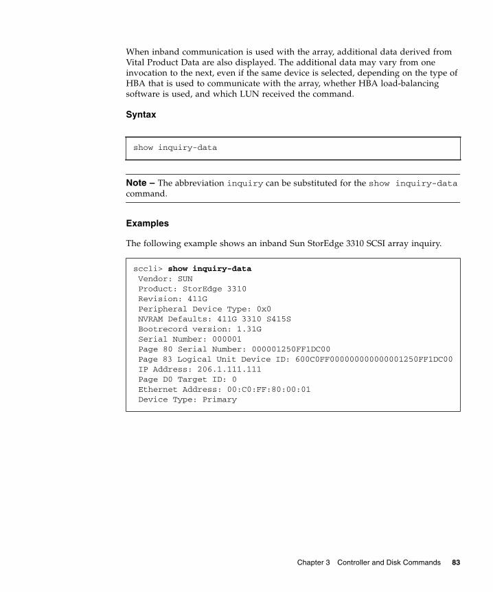
When inband communication is used with the array, additional data derived from Vital Product Data are also displayed. The additional data may vary from one invocation to the next, even if the same device is selected, depending on the type of HBA that is used to communicate with the array, whether HBA load-balancing software is used, and which LUN received the command.
Syntax
Note – The abbreviation inquiry can be substituted for the show inquiry-data command.
Examples
The following example shows an inband Sun StorEdge 3310 SCSI array inquiry.
show inquiry-data
sccli> show inquiry-data Vendor: SUN Product: StorEdge 3310 Revision: 411G Peripheral Device Type: 0x0 NVRAM Defaults: 411G 3310 S415S Bootrecord version: 1.31G Serial Number: 000001 Page 80 Serial Number: 000001250FF1DC00 Page 83 Logical Unit Device ID: 600C0FF000000000000001250FF1DC00 IP Address: 206.1.111.111 Page D0 Target ID: 0 Ethernet Address: 00:C0:FF:80:00:01 Device Type: Primary
Chapter 3 Controller and Disk Commands 83

The following example shows an inband Sun StorEdge 3510 FC array inquiry.
The following example shows an out-of-band Sun StorEdge 3510 FC array inquiry.
show redundancy-mode
Description
The show redundancy-mode command shows whether the two controllers are operating correctly as a redundant pair. Returned values include Active-Active, disabled, enabled, failed, scanning, detected, and primary or secondary.
You can also use the show redundancy-mode command to monitor the status of an automatic firmware update. The Sun StorEdge CLI will display the progression of “Failed,” “Scanning,” “Detected,” and “Enabled” states. Returned values include:
sccli> inquiry Vendor: SUN Product: StorEdge 3510 Revision: 411G Peripheral Device Type: 0x0 NVRAM Defaults: 411G01 3510 S410F Bootrecord version: 1.31H Serial Number: 003CE3 Page 80 Serial Number: 003CE3161637C100 Page 83 Logical Unit Device ID: 600C0FF000000000003CE3161637C100 Page 83 Target Device ID: 206000C0FF003CE3 IP Address: 206.1.111.111 Page D0 Fibre Channel Address: A7 (id 40) Page D0 Node Name: 206000C0FF003CE3 Page D0 Port Name: 216000C0FF803CE3 Ethernet Address: 00:C0:FF:00:3C:E3 Device Type: Primary
# sccli 206.1.111.111 inquirysccli: selected se3000://206.1.111.111:58632 [SUN StorEdge 3510 SN#004DE2] Vendor: SUN Product: StorEdge 3510Revision: 411G NVRAM Defaults: 411G 3510 S415F Bootrecord Version: 1.31H Serial Number: 004DE2 IP Address: 206.1.111.111 Ethernet Address: 00:C0:FF:00:4D:E2
84 Sun StorEdge 3000 Family CLI 2.4 User’s Guide • March 2007

1. Initial Failed Status Response: This is the response to the command upon a controller failure and is shown for completeness.
2. Scanning Status: Install Controller FRU. The installed controller is performing self-test and scanning disk channels. This is also the state where the controller updates the firmware on the newly installed controller if it is not identical to the running firmware version. The controllers can remain in this state for up to 10 minutes depending upon system activity.
3. Detected Status: Redundant Controller Process Starts. The installed controller has completed the scanning of the disk channels, updated installed controller firmware as required, and communicated to the primary controller. This status is transitional and normally cannot be detected unless repetitive operations are executed.
4. Enabled State: Redundant Controller Procedure Completed. The installed controller has completed the redundant controller procedure enabling the active-active operation.
Syntax
Examples
The following example shows the redundancy status is Enabled and the mode is Active-Active for a Sun StorEdge 3510 FC array.
Note – The primary controller location displays as “N/A” for Sun StorEdge 3000 family SCSI arrays. The controller location is provided only for Sun StorEdge 3510 FC arrays and Sun StorEdge 3511 SATA arrays.
show redundancy-mode
sccli> show redundancy-mode Primary controller serial number: 8009328 Primary controller location: Lower Redundancy mode: Active-Active Redundancy status: Enabled Secondary controller serial number: 8009200
Chapter 3 Controller and Disk Commands 85

show redundant-controller
Description
The show redundant-controller command displays the redundant-controller information.
Syntax
Examples
The following example shows the redundant-controller information.
show shutdown-status
Description
The show shutdown-status command displays the controller shutdown status.
Syntax
show redundant-controller
sccli> show redundant-controller Redundant Controller Configuration: primary Cache Synchronization: enabled Host Channel Failover Mode: shared Local/Remote Redundant Mode: local Write-Through Data Synchronization: enabled Secondary RS-232 Port Status: disabled Communication Channel Type: SCSI
show shutdown-status
86 Sun StorEdge 3000 Family CLI 2.4 User’s Guide • March 2007

Examples
The following example shows the controller shutdown is complete.
Status values include:
■ Controller-online – No pending or previously issued shutdown command■ Shutdown-busy – Busy with another shutdown command■ Shutdown-in-progress – Shutdown in progress■ Shutdown-complete – Controller shutdown complete■ Unknown – Unknown status
show unique-identifier
Description
The show unique-identifier command displays the RAID controller unique identifier. A valid controller unique identifier is a hexidecimal number from 0 to 0xfffff. It is displayed as a six-digit value, where the first digit is always 0 for consistency with the presentation of FRU serial numbers. The default value for the unique ID is the FRU serial number of the midplane/chassis in which the controller resides.
Syntax
Examples
The following example shows the unique identifier is 00476F.
sccli> shutdown controllerWARNING: This is a potentially dangerous operation.The array will remain offline until it is reset.Data loss may occur if the controller is currently in use.Do you want to reset the controller now? ysccli: shutting down controller...sccli: controller is shut downsccli> show shutdown-status Controller shutdown complete.
show unique-identifier
sccli> show unique-identifier unique-identifier: 00476F
Chapter 3 Controller and Disk Commands 87

shutdown controller
Description
The shutdown controller command shuts down the RAID controller and stops I/O processing. This temporarily causes the array to go offline, which might affect applications running on any hosts connected to the array. Data in the controller cache is flushed to logical drives. After issuing this command, issue the reset controller command.
Caution – The shutdown command causes the array to stop responding to I/O requests from the host. This might result in data loss unless all I/O activity is suspended by halting all applications that are accessing the array, and unmounting any file systems that are mounted from the array. In redundant-controller configurations, these commands affect all LUNs on both controllers.
Note – Use this command whenever the RAID array is powered off. It ensures that all data is written to disk, and that the backup battery (if present) is not drained by the cache memory.
Note – A controller shutdown does not generate an event message. To view the status of the shutdown, use the show shutdown-status command. For details, see “show shutdown-status” on page 86.
Syntax
Examples
The following example shows the message prompts that are displayed when you run the shutdown controller command.
shutdown controller
# sccli /dev/rdsk/c0t5d0s2 shutdown controllerWARNING: This is a potentially dangerous operation. The controller will go offline for several minutes. Data loss may occur if the controller is currently in use. Do you want to reset the controller now? ysccli: shutting down controller...sccli: controller is shut down
88 Sun StorEdge 3000 Family CLI 2.4 User’s Guide • March 2007

unfail
Description
The unfail command restores the controller pair to redundant operation. When a primary controller fails, the secondary controller becomes the primary controller. The unfail command makes the initial primary controller the secondary controller.
Note – The unfail command reverses the fail secondary command, permitting the secondary controller to resume operation and restore the controller pair to redundant operation.
Syntax
Examples
The following example reverses the fail secondary command.
upload controller-configuration
Description
The upload controller-configuration command saves a description of the configuration of the array to a user-specified file. The file can be used to restore the same configuration to the array at a later date, or to copy the configuration to another array. The file includes channel settings; host and drive side parameters; array parameters; network port setup; controller general parameters; logical drive, logical volume, and physical drive information; partition information and mappings on host channels. For details on downloading the controller configuration file, see “download controller-configuration” on page 68.
Note – The file contains binary data and cannot be viewed with a text editor.
unfail
sccli> unfailAre you sure? y
Chapter 3 Controller and Disk Commands 89
Syntax
Examples
The following example saves the RAID configuration into the binary file raidcfg.bin.
Disk CommandsThe following commands are explained in this section:
■ abort clone■ clone■ configure global-spare■ scan disk■ set disk-array■ set led■ show clone■ show disk-array■ show disks■ show led-status■ unconfigure global-spare
For details on downloading disk firmware, see “download disk-firmware” on page 177.
abort clone
Description
The abort clone command stops the cloning of the specified disk drive.
To clone a disk, use the clone command. For details, see “clone” on page 91.
To view the progress of a clone, use the show clone command. For details, see “show clone” on page 97.
upload controller-configuration file
# sccli c2t0d0 upload controller-configuration raidcfg.bin
90 Sun StorEdge 3000 Family CLI 2.4 User’s Guide • March 2007

Syntax
Arguments
Examples
The following example aborts the clone disk drive operation for ID 5 on channel 2.
clone
Description
The clone command uses a destination disk to copy and replace a drive that is suspected of failing. The disk that you are replacing must be a member of a logical drive. The clone command is not supported for NRAID arrays.
The clone command might be issued in response to a self-monitoring analysis and reporting technology (SMART) warning. To enable SMART, see “set drive-parameters” on page 108.
Note – You cannot create a logical drive composed of Sun StorEdge 3510 FC drives and Sun StorEdge 3511 SATA drives. If you try to mix drive types in a logical drive, by cloning a disk with a different drive type, an error is displayed. For more information, refer to the Sun StorEdge 3000 Family RAID Firmware User’s Guide.
Syntax
abort clone disk-dest
TABLE 3-6 Arguments for abort clone
Argument Description
disk-dest Specify the disk to stop cloning.
# sccli c2t0d0 abort clone d2.5
clone source-disk dest-disk [priority]
Chapter 3 Controller and Disk Commands 91

Arguments
Examples
The following example copies and replaces disk drive ID 5 on channel 2 with disk drive ID 0 on channel 3.
configure global-spare
Description
The configure global-spare command specifies a global spare disk. The disk drive status is set to standby.
Note – If you connect one or more Sun StorEdge 3511 SATA expansion units to a Sun StorEdge 3510 FC array, configure an FC drive and a SATA drive as global spares. Then, if a drive fails in the RAID chassis, a FC global spare is used to replace the failed drive. Or, if a drive fails in the SATA expansion unit, a SATA global spare is used to replace the failed drive. If a failure occurs and the appropriate drive type is not available as a global spare, the failed drive will not be replaced automatically. For more information, refer to the Sun StorEdge 3000 Family RAID Firmware User’s Guide.
Syntax
TABLE 3-7 Arguments for clone
Argument Description
source-disk Specify the disk to copy and replace. For example, specify the source disk with target ID 1 on channel 2 as 2.1.
dest-disk Specify the disk to use as the replacement. For example, specify the destination disk with target ID 3 on channel 2 as 2.3.
priority Specify the priority of the disk replacement. Valid values: low, normal, improved, high. The higher the priority selected, the greater amount of system resources required to perform the clone. For example, specify low to have the replacement occur using minimal system resources.
# sccli c2t0d0 clone d2.5 d3.0
configure global-spare disk
92 Sun StorEdge 3000 Family CLI 2.4 User’s Guide • March 2007

Arguments
Examples
The following example configures disk drive ID 5 on channel 2 as a global spare.
scan disk
Description
The scan disk command scans and makes available a hard drive without having to shut down the array. When a Sun StorEdge 3000 family SCSI array is powered on, the controller scans all physical drives that are connected through drive channels. Unlike Sun StorEdge 3000 FC and SATA arrays, if a Sun StorEdge 3000 family SCSI array has completed initialization and then a physical drive is connected, the controller does not automatically recognize the new drive until the next controller reset. This difference in behavior is due to differences between Fibre Channel and SCSI architectures and protocols.
Note – This command is supported on Sun StorEdge 3000 SCSI arrays only.
Syntax
TABLE 3-8 Arguments for configure global-spare
Argument Description
disk Specify the disk to configure. For example, specify the disk with target ID 1 on channel 2 as 2.1. When you assign a global spare, the system automatically assigns global spare status to the unassigned drive with the lowest drive ID. This enables the array to use the global spare to rebuild a logical drive automatically without user intervention when a failing drive needs to be replaced.
# sccli c2t0d0 configure global-spare 2.5
scan disk [disk-list]
Chapter 3 Controller and Disk Commands 93
Arguments
Examples
The following example scans disk 2.
set disk-array
Description
The set disk-array command sets disk array parameters including the background logical drive rebuilding priority and hard drive data verification.
Syntax
TABLE 3-9 Arguments for scan disk
Argument Description
disk-list Scans specific disks. Use any of the following formats: ch.id, ch.idm-n. ch is physical device channel, id is the SCSI ID of the device, and m to n represents a contiguous range of IDs on the same channel. For example, 2.0, 2.3 or 2.2-5.
sccli> scan disk d2.11
set disk-array [normal-verify value| rebuild-verify value | init-verify value] [rebuild-priority value]
94 Sun StorEdge 3000 Family CLI 2.4 User’s Guide • March 2007

Arguments
Examples
The following example specifies that data is verified during the rebuilding process and when initializing logical drives.
set led
Description
The set led command changes the drive LED for the specified disk (or slot) from green to amber. For Sun StorEdge 3000 family SCSI JBODs, specify a disk device using a Solaris device name such as sd31 or c1t0d0s2, or specify a slot number. Use the show led-status command to show the status of the identified disk drive.
Note – This command does not support Sun StorEdge 3510 FC JBODs or Sun StorEdge 3511 SATA JBODs.
TABLE 3-10 Arguments for set disk-array
Argument Description
normal-verify
{enabled | disabled}
Specify whether to perform Verify-after-Write during normal I/O requests. This method affects write performance during normal use.
rebuild-verify
{enabled | disabled}
Specify whether to perform Verify-after-Write during the rebuilding process.
init-verify
{enabled | disabled}
Specify whether to perform Verify-after-Write while initializing the logical drive.
rebuild-priority
Specify the priority of the logical drive rebuild process. Valid values: low, normal, improved, high. The higher the priority selected, the greater amount of system resources required. For example, specify low to perform the rebuild after other firmware processes complete.
sccli> set disk-array rebuild-verify enabled init-verify enabled
Chapter 3 Controller and Disk Commands 95

Note – Selecting a slot by disk name is not supported in split-bus enclosure configurations because the enclosure services processor resides on only one of the internal buses and the Sun StorEdge CLI might not be able to determine the slot location of a particular device. In such configurations, use the show enclosure-status command and the disk documentation provided with your enclosure to determine the correct slot number instead.
Syntax
To change a specific drive LED in a RAID array from green to amber, use the following parameters.
To change a specific drive LED in a Sun StorEdge 3000 family SCSI JBOD from green to amber, use the following parameters.
Arguments
set led disk ch.id {on | off}
set led {slot n | disk sdn | disk cXtYdZ} {on | off}
TABLE 3-11 Arguments for set led
Argument Description
slot n Changes the drive LED from green to amber for the specified disk drive slot.
disk sdn Changes the drive LED from green to amber for the specified Solaris disk drive slot.
disk cXtYdZ Changes the drive LED from green to amber for the specified Solaris disk drive slot.
ch.id Changes the drive LED from green to amber for the specified drive within a RAID subsystem.
{on | off} Specify whether to change the LED from green to amber.
96 Sun StorEdge 3000 Family CLI 2.4 User’s Guide • March 2007

Examples
The following example changes the drive with SCSI address 8 from green to amber in the enclosure associated with the enclosure device /dev/es/ses0.
show clone
Description
The show clone command displays the progress of disk cloning.
Syntax
Examples
The following example returns information for the disks being cloned on the specified device.
show disk-array
Description
The show disk-array command displays the disk array parameters including the logical drive rebuild priority and the hard drive settings for verifying the written data for initializing, rebuilding, and writing normal I/O data.
Syntax
sccli> set led disk 0.8 on (enclosure sn 005362) led-slot-0: on
show clone
sccli> clone d2.5 d0.5sccli: start clone 2.5 to 0.5sccli> show clone Ch ID Status------------------- 0 5 2% complete
show disk-array
Chapter 3 Controller and Disk Commands 97

Examples
The following example returns the disk array parameter information.
show disks
Description
The show disks command displays information about the disk drives in the array enclosure and any expansion chassis. Information returned includes the following: channel and ID, negotiated speed, associated logical drive, capacity (size), status, vendor information, mirror output, and worldwide node name (WWNN).
Note – Mirror output is valid only for RAID 1 logical drives.
Syntax
Arguments
sccli> show disk-array init-verify: disabled rebuild-verify: disabled normal-verify: disabled rebuild-priority: low
show disks [disk-list | channel {ch} | free | all] [-b | --buffer-size]
TABLE 3-12 Arguments for show disks
Argument Description
disk-list Shows specific disks. Use any of the following formats: ch.id, ch.idm-n. ch is physical device channel, id is the SCSI ID of the device, and m to n represents a contiguous range of IDs on the same channel. For example, 2.0, 2.3, or 2.2-5.
channel ch Shows all disks on the specified channel.
all Shows all disk drives.
free Shows all unassigned disks.
-b, --buffer-size
Shows the disk buffer size.
98 Sun StorEdge 3000 Family CLI 2.4 User’s Guide • March 2007

Examples
The following example returns information for disks ID 0, ID 3, and ID 7 on channel 2.
The following example returns information for disks on channel 2 for disks 3 through 7, and for channel 1 disk 4.
The following example shows all disk information.
# sccli c2t0d0 show disks 2.0,2.3,2.7
# sccli c2t0d0 show disks 2.3-7,1.4
sccli> show disksCh Id Size Speed LD Status IDs Rev----------------------------------------------------------------------------2(3) 3 33.92GB 200MB NONE FRMT SEAGATE ST336752FSUN36G 0205 S/N 3ET0N0V000007303 WWNN 20000004CFAB138F Mirror (2.3)2(3) 6 33.92GB 200MB ld0 ONLINE SEAGATE ST336753FSUN36G 0349 S/N 3HX0YEJT00007349 WWNN 2000000C50332BFD Mirror (2.6)2(3) 7 33.92GB 200MB ld0 ONLINE SEAGATE ST336753FSUN36G 0349 S/N 3HX0Y6J300007349 WWNN 2000000C503335DC Mirror (2.7)2(3) 8 33.92GB 200MB ld0 ONLINE SEAGATE ST336753FSUN36G 0349 S/N 3HX0YC1Y00007349 WWNN 2000000C503334AE Mirror (2.8)2(3) 9 33.92GB 200MB ld0 ONLINE SEAGATE ST336753FSUN36G 0349 S/N 3HX0Y7W100007349 WWNN 2000000C50332BBE Mirror (2.9)2(3) 10 33.92GB 200MB NONE FRMT SEAGATE ST336753FSUN36G 0349 S/N 3HX0YAQF00007349 WWNN 2000000C50333AB8 Mirror (2.10)
Chapter 3 Controller and Disk Commands 99

Note – All device capacity is displayed in powers of 1024. For details, see “Device Capacity” on page 15.
Returned Values
Returned values include channel number, disk SCSI ID, size, speed (megabytes per second), logical drive assignment, status, drive model ID, firmware revision, serial number, and device node name. If the -b option is specified, the drive buffer size and drive serial number are displayed.
Logical drive assignment values include:
■ Global – global spare■ None – unassigned
Speed values include:
■ Async – SCSI Asynchronous■ SYNC – SCSI Synchronous■ 20MB – SCSI Ultra■ 40MB – SCSI Ultra Wide■ 80MB – SCSI Ultra2■ 160MB – SCSI 160■ 320MB – SCSI Ultra3■ 100MB – FC 1GB/s■ 200MB – FC 2 GB/s
Status values include:
■ Online – in good condition■ Global – global spare■ Stand-By – standby for global or local spare■ Initing – initialization in progress■ Rebuild – rebuild in progress■ Adding – adding disk in progress■ In_Clone – drive is in process of cloning another drive■ Forclone – drive is a valid clone of another drive■ Copying – drive is in process of copying from another drive■ New – new disk that has not been configured■ Used – contains RAID meta data■ Bad – failed disk■ Absent – disk does not exist■ Missing – configured disk is missing■ SB-Miss – configured spare drive is missing■ FRMT – drive was part of a logical drive that no longer exists, but the controller
still recognizes the logical drive data format contained on it
100 Sun StorEdge 3000 Family CLI 2.4 User’s Guide • March 2007

■ None – not assigned■ Good – no operation in progress■ M – media check in progress
show led-status
Description
The show led-status command displays the status of the LED adjacent to the specified disk drive slot in the array enclosure or expansion chassis. Returned values include on and off. If the value is on, the LED of the specified drive is amber. If the value is off, the LED of the specified drive is green if it is working properly.
Note – This command does not support Sun StorEdge 3510 FC JBOD devices or Sun StorEdge 3511 SATA JBOD devices.
Syntax
To display the status of LEDs in LVD RAID enclosures, use the following syntax.
To show the status of LVD JBOD enclosures, use the following syntax.
show led-status
show led-status disk ch.id
show led-status {slot n | disk sdn | disk cXtYdZ}
Chapter 3 Controller and Disk Commands 101

Arguments
Examples
The following example shows the status of the LED adjacent to the disk assigned to drive slot 3 for an expansion chassis.
The following example shows the status of the LED adjacent to the disk assigned to drive slot 2 for the RAID array.
unconfigure global-spare
Description
The unconfigure global-spare command unconfigures a global spare disk.
Syntax
TABLE 3-13 Arguments for show led-status
Argument Description
slot n Shows the status for the LED adjacent to the specified disk drive slot. This argument is not accepted for RAID controllers.
disk sdn Shows the status for the LED adjacent to the specified Solaris disk drive slot. This argument is not accepted for split-bus configurations.
disk cXtYdZ Shows the status for the LED adjacent to the specified Solaris disk drive slot. This argument is not accepted for split-bus configurations.
ch.id Shows the status for the LED adjacent to the specified drive within a RAID array.
sccli> show led-status slot 3(enclosure sn 002A4C) led-slot-3: on
sccli> show led-status disk 2.0 (enclosure sn 002A4C) led-slot-0: off
unconfigure global-spare disk
102 Sun StorEdge 3000 Family CLI 2.4 User’s Guide • March 2007

Arguments
Examples
The following example unconfigures disk drive ID 5 on channel 2 as a global spare.
TABLE 3-14 Arguments for unconfigure global-spare
Argument Description
disk Specify the disk to unconfigure. For example, specify the disk with target ID 1 on channel 2 as 2.1.
# sccli c2t0d0 unconfigure global-spare 2.5
Chapter 3 Controller and Disk Commands 103

104 Sun StorEdge 3000 Family CLI 2.4 User’s Guide • March 2007

CHAPTER 4
Channel Commands
This chapter provides the available host, drive, and redundant controller communication (RCCOM) channel commands with sample code.
Note – To prevent unauthorized access to administrative functions of the RAID controller, the Sun StorEdge CLI requires superuser or system administrator privileges for inband access, and uses the controller password to authorize users of the out-of-band interface.
Note – If no command is entered on the command line, the Sun StorEdge CLI enters an interactive mode, prompting you to enter commands until the quit command is entered. All commands operate on the currently selected device.
105

Channel CommandsThe following commands are explained in this section:
■ configure channel■ set drive-parameters■ set host-parameters■ set inter-controller-link■ show channels■ show drive-parameters■ show host-parameters■ show inter-controller-link
configure channel
Description
The configure channel command configures host, drive, or RCCOM channels and establishes channel IDs on the primary and secondary controller. The most common reason to change a channel setting is to change a host channel to a drive channel to attach expansion units to a RAID array. After a channel configuration change, the RAID controller must be reset.
Caution – All reset commands cause the array to stop responding to I/O requests from the host for a period of time. This might result in data loss unless all I/O activity is suspended by halting all applications that are accessing the array, and unmounting any file systems that are mounted from the array. In redundant-controller configurations, these commands affect all LUNs on both controllers. After running a reset command, to stay in prompt mode, run the select command to reselect the device.
Note – If a primary ID is not mapped to a channel, and a secondary ID is mapped, “Async” displays in the Speed field when the show channels command is run. For details, see “show channels” on page 113.
Syntax
configure channel channel [{host|drive|RCCOM}] [primary-id target-list] [secondary-id target-list] [-r | --reset]
106 Sun StorEdge 3000 Family CLI 2.4 User’s Guide • March 2007

Arguments
Examples
The following example sets the channel mode as host and resets the controller immediately.
The following example sets the channel primary ID as 112 and the secondary ID as 114 and 115.
TABLE 4-1 Arguments for configure channel
Argument Description
channel channel Specify the physical drive channel. Use the following format: {p}[,..{q}[,….{n}]]. Valid values include 0–5 or 0–7.
[host | drive| RCCOM]
Specify whether the channel is used to interface with a host or disk drive, or assigned to RCCOM. If the channel is configured as a host channel, multiple IDs can be applied. However, if the channel is configured as a drive channel, only one ID can be applied.
primary-id target-list
Specify one or more comma-separated target IDs for the primary controller on the specified channel. Specify None if you do not want to configure a primary ID. primary-id can be abbreviated pid. Valid values: None (no ID configured), 0–15 for SCSI devices, and 0–125 for FC and SATA devices.
secondary-id target-list
Specify one or more comma-separated target IDs for the secondary controller. Specify None if you do not want to configure a secondary ID. secondary-id can be shortened to sid. Valid values: None (no ID configured), 0–15 for SCSI devices, and 0–125 for FC and SATA devices.
[-r | --reset] Specify that the controller reset immediately so that the specified changes take effect. By default, the specified changes do not take effect until a reset controller command is issued.
# sccli c2t0d0 configure channel 0 mode host --reset
# sccli c2t0d0 configure channel 0 primary-id 112 secondary-id 114,115
Chapter 4 Channel Commands 107
set drive-parameters
Description
The set drive-parameters command sets the specified RAID controller parameters that affect the operation of drive channels. For details about configuring a drive channel, see “configure channel” on page 106.
Caution – Do not change the scsi-io-timeout argument. Setting the timeout to a lower value causes the controller to judge a drive as failed while a drive is still retrying or while a drive is unable to arbitrate the SCSI bus. Setting the timeout to a greater value causes the controller to keep waiting for a drive, and it might cause a host timeout.
Syntax
Arguments
set drive-parameters parameter-name value
TABLE 4-2 Arguments for set drive-parameters
Argument Description
scsi-io-timeout Specify the time interval for the controller to wait for a disk drive to respond. If the controller attempts to read data from or write data to a drive but the drive does not respond within the SCSI I/O timeout value, the drive is considered a failed drive. Valid values: 500ms, 1s, 2s, 4s, 6s, 7s, 8s, 10s, 15s, 20s, 30s (default).
spin-up {enabled | disabled}
This parameter is reserved and should be used only by qualified technicians. Specify whether the disk drives are powered up sequentially when the array powers up. When the power supply is unable to provide sufficient current for all physical drives and controllers that are powered on at the same time, spinning-up the physical drives serially requires less current. Valid values: enabled, disabled.
disk-access-delay
Specify the amount of time that the controller waits before it tries to access the physical drives after power-on. The default value is 15 seconds. Valid values: 0s, 5s, 10s, 15s (default), ...75s (increments of 5 between 0–75).
108 Sun StorEdge 3000 Family CLI 2.4 User’s Guide • March 2007

queue-depth Specify the maximum queue depth (tag count) that the controller uses when queuing commands for each disk drive. To indicate that the queue depth value can be computed automatically, specify the value 0. The default value is 32. Valid values: 0 (disable), 1, 2, 4, 8, 16, 32, 64, 128.
polling-interval
Specify the interval at which the array controller polls the disk drives. The default value is 0 (disabled), which means if there is no activity on the bus, the controller does not know if a drive has failed or has been removed. Setting an interval enables the program to detect a drive failure when there is no array activity; however, performance is degraded. Valid values: 0 (disable), 500ms, 1s, 2s, 5s, 10s, 30s.
enclosure-polling-interval
Specify the interval at which the array controller polls the SAF-TE or SES environmental services processor in the enclosure. The default value of 0 specifies that polling is disabled. Valid values: 0 (disabled), 50ms, 100ms, 200ms, 500ms, 1s, 2s, 5s, 10s, 20s, 30s, 60s.
auto-detect-swap-interval
Specify the interval between checks to determine if a failed drive has been physically replaced. The default value of 0 specifies that auto-detecting is disabled. Valid values: 0, 5s, 10s, 15s, 30s, 60s.
smart Specify whether the disk drives perform predictive failure (SMART) analysis. Valid values: disabled, detect-only, detect-perpetual-clone, detect-clone-replace.• Detect-only predicts symptoms of drive failure, but only writes
an error message to the controller event log.• Detect-perpetual-clone detects future problems and clones a
spare drive so that it is ready when failure does occur. The spare drive stays mirrored to the source drive (the drive whose failure has been predicted) but does not replace it until the source drive fails.
• Detect-clone-replace detects future problems, clones a spare drive, and immediately uses the cloned drive to replace the source drive whose failure is predicted.
auto-global-spare {enabled | disabled}
Specify whether the RAID controller automatically allocates disk drives as global spares. When you enable this option, the system automatically assigns a global spare to the unassigned drive with the lowest drive ID. This enables the array to use the global spare to rebuild a logical drive automatically without user intervention when a failing drive needs to be replaced. Valid values: enabled, disabled.
TABLE 4-2 Arguments for set drive-parameters (Continued)
Argument Description
Chapter 4 Channel Commands 109

Examples
The following example sets the SCSI I/O timeout to 30 seconds.
The following example sets the queue depth to 32 (the default value).
The following example sets the interval of drive polling to 10 seconds and disables SMART monitoring.
set host-parameters
Description
The set host-parameters command sets the specified host-channel related parameters including the maximum number of LUNs per target address, queue depth, inband management access, and the FC connection mode (FC and SATA devices only). For details about configuring a host channel, see “configure channel” on page 106.
Note – If inband management is disabled by the Sun StorEdge CLI, the RAID firmware application, or Sun StorEdge Configuration Service, and a user attempts to use inband management, the message “RAID controller not responding” displays when a Sun StorEdge CLI command is run. If this occurs, use out-of-band management to access the RAID controller with the Sun StorEdge CLI. For details, see “Device Names for Out-of-Band Communication” on page 11.
Syntax
# sccli c2t0d0 set drive-parameters scsi-io-timeout 30s
# sccli c2t0d0 set drive-parameters queue-depth 32
# sccli c2t0d0 set drive-parameters poll-interval 10s smart disabled
set host-parameters [queue-depth value] [max-luns-per-id value] [fibre-connection-mode] [inband-management value]
110 Sun StorEdge 3000 Family CLI 2.4 User’s Guide • March 2007

Arguments
Examples
The following example sets the maximum I/O number in the controller queue to 16.
The following example sets the maximum LUN number of each SCSI ID to 8.
TABLE 4-3 Arguments for set host-parameters
Argument Description
max-luns-per-id Specify the maximum number of LUNs that can be assigned to any one host ID (target address). Each time a host channel ID is added, it uses the number of LUNs allocated in this setting. The default setting is 32 LUNs. Valid values: 1, 2, 4, 8, 16, 32.
queue-depth Specify the maximum number of I/O operations that can be queued simultaneously for a given logical drive. The default value is 1024. Valid values: 0 (auto), 1, 2, 4, 8, 16, 32, 64, 128, 256, 512, 1024.
fibre-connection-mode FC and SATA devices only. Specify the connection mode. • Loop configures an arbitrated loop, which can be used with Direct
Attached Storage (DAS) or Storage Area Network (SAN) configurations. Fibre Channel-Arbitrated Loop (FC-AL) supports only half-duplex communication, but allows up to eight IDs per channel.
• Point-to-point can be used only with a switched fabric network, also called a Storage Area Network (SAN) configuration. Point-to-Point protocol supports full duplex communication, but only allows one ID per channel.
Valid values: loop, point-to-point.
inband-management {enabled | disabled}
Specify whether users can access Sun StorEdge CLI and Sun StorEdge Configuration Service using inband communication over a FC or SCSI channel. If this argument is disabled, out-of-band access must be used. For more information about out-of-band access, see “Device Names for Out-of-Band Communication” on page 11. Valid values: enabled, disabled.
# sccli c2t0d0 set host-parameters queue-depth 16
# sccli c2t0d0 set host-parameters max-luns-per-id 8
Chapter 4 Channel Commands 111

set inter-controller-link
Description
Redundant Sun StorEdge 3000 family FC and SATA arrays only. The set inter-controller-link command connects or disconnects an individual port on the upper of lower RAID controller in a redundant-controller configuration. For the Sun StorEdge 3510 FC array, the two controllers are effectively disconnected (on that channel) if either one of the two inter-controller links are disconnected because host channels on both Sun StorEdge 3510 FC controllers are controlled by the same port. For the Sun StorEdge 3511 SATA array, the command must be run for each individual channel and slot location because host channels on the primary and secondary controller are controlled by different ports.
Caution – If the controllers are not connected, host applications might not experience transparent failover in the event of a controller failure.
Syntax
Note – icl can be substituted for the keywords inter-controller-link.
set inter-controller-link {upper|lower} channel channel {connected|disconnected}
112 Sun StorEdge 3000 Family CLI 2.4 User’s Guide • March 2007

Arguments
Examples
The following example disconnects the port on lower channel 1.
The following example sets the port bypass circuit for channel 5 on the upper controller slot to enabled.
show channels
Description
The show channels command displays information about host, drive, and RCCOM channels including the channel number, channel mode, primary and secondary ID, speed, and connection mode.
TABLE 4-4 Arguments for set inter-controller-link
Argument Description
{upper | lower} Specify the location of the array controller slot, upper or lower.
channel ch Specify the channel to modify. Valid values: 0, 1, 4, 5.
{connected | disconnected}
Specify the desired state for the port bypass circuit. Usually, all inter-controller links on both the upper and lower controllers are connected. For the Sun StorEdge 3510 FC array, disconnecting the upper or lower controller’s inter-controller link on any given host channel breaks the internal connection between the two controllers, and between the upper controller and the external connector on the lower controller and vice versa. For the Sun StorEdge 3511 SATA array, you must disconnect the upper and lower host channel to disconnect the inter-controller link.Disconnecting the inter-controller link potentially doubles aggregate bandwidth because the controllers do not have to share bandwidth on each channel; and, it also prevents controller failover from working.
# sccli c2t0d0 set inter-controller-link lower channel 1 disconnected
# sccli c2t0d0 set icl upper channel 5 connected
Chapter 4 Channel Commands 113

Syntax
Arguments
Examples
The following example returns information for channels 0 and 2.
The following example returns all channel information for a Sun StorEdge 3510 FC array.
Returned Values
Returned values include channel number, channel type, media (node), speed, width, primary ID (PID), and secondary ID (SID).
show channels [channel-list]
TABLE 4-5 Arguments for show channels
Argument Description
channel-list Specify the channel. The format for channel-list is {n}[,...{m}] or a range format “{n}-{m}” or {n}[,...{p}-{m}]. Valid channel numbers include: 0–7 or 0–5 depending on the hardware. If {m} is greater than the largest channel number, information for all the channels is displayed.
# sccli c2t0d0 show channels 0,2
sccli> show channelsCh Type Media Speed Width PID / SID-------------------------------------------- 0 Host FC(L) 2G Serial 40 / 41 1 Host FC(L) 2G Serial 43 / 42 2 DRV+RCC FC(L) 2G Serial 14 / 15 3 DRV+RCC FC(L) 2G Serial 14 / 15 4 Host FC(L) 2G Serial 44 / 45 5 Host FC(L) 2G Serial 47 / 46 6 Host LAN N/A Serial NA / NA
114 Sun StorEdge 3000 Family CLI 2.4 User’s Guide • March 2007

Channel type values include:
■ Host ■ DRV (Drive) ■ RCC (RCCOM)
Media (mode) values include:
■ L – loop mode (FC and SATA only)■ P – point-to-point (FC and SATA only)■ SCSI■ FC■ LAN – network channel
Speed values include:
■ Async – ■ For SCSI, SCSI Asynchronous ■ For FC or SATA, no link or link down
■ SYNC – SCSI Synchronous■ Ultra – SCSI Ultra■ Ultra2 – SCSI Ultra2■ U160 – SCSI U160■ U320 – SCSI U320■ 1G – FC 1 GB/s■ 2G – FC 2 GB/s
Note – Speed values are displayed for the primary controller only. Therefore, if a user maps one LUN to the primary controller, and another LUN to a secondary controller, only the established connection to the primary controller is displayed. As a result, if a primary ID is not mapped to a channel, and a secondary ID is mapped, “Async” displays in the Speed field.
PID (primary ID) / SID (secondary ID) values include:
■ SCSI 0-15
■ FC and SATA 0-125
■ When multiple IDs exist for the primary ID or secondary ID, an asterisk (*) displays in the PID or SID field.
show drive-parameters
Description
The show drive-parameters command displays the specified RAID controller parameters pertinent to the operation of disk drives and enclosure services connected to drive channels.
Chapter 4 Channel Commands 115

Syntax
Examples
The following example shows all drive parameters of the Sun StorEdge 3510 FC array.
Returned Values
The returned values for the show drive-parameters command are described in the following table.
show drive-parameters
sccli> show drive-parameters spin-up: disabled disk-access-delay: 15s scsi-io-timeout: 30s queue-depth: 32 polling-interval: disabled enclosure-polling-interval: 30s auto-detect-swap-interval: disabled smart: disabled auto-global-spare: disabled
TABLE 4-6 Output for show drive-parameters
Field Description
spin-up {enabled | disabled}
Specifies whether the disk drive automatically spins up on power up. Valid values: enabled, disabled.
disk-access-delay
The delay in seconds or milliseconds before disk access is granted.
scsi-io-timeout Delay in seconds before disk drive I/O timeout. Valid values: 500ms, 1s, 2s, 4s, 6s, 7s, 8s, 10s, 15s, 20s, 30s (default).
queue-depth Maximum queue depth that the controller uses when queuing commands for each disk drive. The default value is 32. Valid values: 0 (disabled), 1, 2, 4, 8, 16, 32, 64, 128.
polling-interval
Specifies the interval at which the array controller polls the disk drives. Valid values: 0 (disable), 500ms, 1s, 2s, 5s, 10s, 30s.
116 Sun StorEdge 3000 Family CLI 2.4 User’s Guide • March 2007

show host-parameters
Description
The show host-parameters command displays the maximum I/O queue depth per LUN, the number of LUNs that can be configured per target ID, the fibre connection mode (point-to-point or loop for FC and SATA only), and inband management access. To view the partitions mapped to specific host channels, use the show lun-maps command. For details, see “show lun-maps” on page 158.
Syntax
Examples
The following example shows the host parameters for a Sun StorEdge 3510 FC array.
enclosure-polling-interval
Specifies the interval at which the array controller polls the SAF-TE or SES environmental services processor in the enclosure. Valid values: 0 (disabled), 50ms, 100ms, 200ms, 500ms, 1s, 2s, 5s, 10s, 20s, 30s, 60s.
auto-detect-swap-interval
Interval (in milliseconds) between checks to determine if a failed drive has been physically replaced. The default value of 0 specifies that auto-detecting is disabled. Valid values: 0, 5s, 10s, 15s, 30s, 60s.
smart Determines whether the disk drives perform predictive failure analysis. Valid values: disabled, detect-only, detect-perpetual-clone, detect-clone-replace.
auto-global-spare {enabled | disabled}
Specifies whether the RAID controller automatically allocates disk drives as global spares. Valid values: enabled, disabled.
show host-parameters
sccli> show host-parameters max-luns-per-id: 32 queue-depth: 1024 fibre-connection-mode:loop inband-management: enabled
TABLE 4-6 Output for show drive-parameters (Continued)
Field Description
Chapter 4 Channel Commands 117

The following example shows the host parameters for a Sun StorEdge 3310 SCSI array.
show inter-controller-link
Description
Redundant Sun StorEdge 3000 family FC and SATA arrays only. The show inter-controller-link command displays the status of the port bypass circuit for the specified channel on the array controller in the upper or lower slot. If specified, the arguments must specify an array controller slot location and a channel specifier. If no arguments are specified, the upper and lower slots of channels 0, 1, 4, and 5 are displayed.
Syntax
Note – icl can be substituted for the keywords inter-controller-link.
Arguments
sccli> show host-parameters max-luns-per-id: 32 queue-depth: 1024 inband-management: enabled
show inter-controller-link {upper | lower} channel ch
TABLE 4-7 Arguments for show inter-controller-link
Argument Description
{upper | lower} Specify the upper or lower controller slot in the chassis to which the command is directed.
channel ch Specify the channel number of the inter-controller link.
118 Sun StorEdge 3000 Family CLI 2.4 User’s Guide • March 2007

Examples
The following example shows the inter-controller links for channels 0, 1, 4, and 5.
# sccli 111.1.111.11 show inter-controller-link inter-controller-link upper channel 0: connected inter-controller-link lower channel 0: connected inter-controller-link upper channel 1: connected inter-controller-link lower channel 1: connected inter-controller-link upper channel 4: connected inter-controller-link lower channel 4: connected inter-controller-link upper channel 5: connected inter-controller-link lower channel 5: connected
Chapter 4 Channel Commands 119

120 Sun StorEdge 3000 Family CLI 2.4 User’s Guide • March 2007

CHAPTER 5
Logical Drive, Partition, and Logical Volume Commands
This chapter provides the available Sun StorEdge CLI commands with sample code for logical drives, partitions, and logical volumes. Topics covered in this chapter include:
■ “Logical Drive Commands” on page 122■ “Partition Commands” on page 153■ “Logical Volume Commands” on page 163
Note – To prevent unauthorized access to administrative functions of the RAID controller, the Sun StorEdge CLI requires superuser or system administrator privileges for inband access, and uses the controller password to authorize users of the out-of-band interface.
Note – If no device is specified on the command line, and more than one array is connected to the host, a menu of devices is presented with one device file name for each array. If there is only one Sun StorEdge 3000 family array connected to the host, that device is selected automatically.
Note – Logical drive indexes can change whenever a logical drive is deleted, while a logical drive identifier never changes over the life of the logical drive.
121

Logical Drive CommandsThe following commands are explained in this section:
■ abort create■ abort expand■ abort media-check■ abort parity-check■ abort rebuild■ add disk■ check parity■ check media■ configure local-spare■ create logical-drive■ delete logical-drive■ expand■ rebuild■ set logical-drive■ show disks logical-drive■ show logical-drive■ show logical-drives expanding■ show logical-drives initializing■ show logical-drives logical volume■ show logical-drives parity-check■ show logical-drives rebuilding■ show media-check■ show stripe-size-list■ shutdown logical-drive■ unconfigure local-spare
abort create
Description
The abort create command stops the creation of a logical drive.
To create a logical drive, use the create logical-drive command. For details, see “create logical-drive” on page 131. To view logical drives, use the show logical-drive command. For details, see “show logical-drive” on page 142.
Syntax
abort create {ld-index | ld-id}
122 Sun StorEdge 3000 Family CLI 2.4 User’s Guide • March 2007

Arguments
Examples
The following example stops the creation of logical drive 8.
abort expand
Description
The abort expand command stops the expansion of a logical drive.
To expand a logical drive, use the expand command. For details, see “expand” on page 135. To view the progress of an expansion, use the show logical-drives expanding command. For details, see “show logical-drives expanding” on page 144.
Syntax
Arguments
TABLE 5-1 Arguments for abort create
Argument Description
ld-index Specify the logical drive index number. For example, ld3.
ld-id Specify the logical drive ID. For example, 71038221.
sccli> abort create ld8
abort expand {ld-index | ld-id}
TABLE 5-2 Arguments for abort expand
Argument Description
ld-index Specify the logical drive index number. For example, ld3.
ld-id Specify the logical drive ID. For example, 71038221.
Chapter 5 Logical Drive, Partition, and Logical Volume Commands 123

Examples
The following example stops the expansion of logical drive 8.
abort media-check
Description
The abort media-check command stops a media check on specified disks or all member disks of the specified logical drive.
For more information on the check media command, see “check media” on page 127.
Note – The front-panel LEDs for the drives being checked will blink until the media check is finished or aborted. For more information about LEDs, refer to the Sun StorEdge 3000 Family Installation, Operation, and Service Manual for your array.
Syntax
Arguments
sccli> abort expand ld8
abort media-check {disk-list | ld-index | ld-id}
TABLE 5-3 Arguments for abort media-check
Argument Description
disk-list Shows specific disks. Use any of the following formats: ch.id, ch.idm-n. ch is physical device channel and id is the SCSI ID of the device and m to n represents a contiguous range of IDs on the same channel. For example, 2.0, 2.3 or 2.2-5.
ld-index Specify the logical drive index number. For example, ld3.
ld-id Specify the logical drive ID. For example, 71038221.
124 Sun StorEdge 3000 Family CLI 2.4 User’s Guide • March 2007

Examples
The following example stops the media check for all member disks of logical drive 5.
abort parity-check
Description
The abort parity-check command stops the parity check on the specified logical drive.
To check parity, use the check-parity command. For details, see “check parity” on page 128. To view the progress of a parity check, use the show logical-drives parity-check command. For details, see “show logical-drives parity-check” on page 148.
Syntax
Arguments
Examples
The following example stops the parity check on logical drive 0.
sccli> abort media-check ld5
abort parity-check {ld-index | ld-id}
TABLE 5-4 Arguments for abort parity-check
Argument Description
ld-index Specify the logical drive index number. For example, ld3.
ld-id Specify the logical drive ID. For example, 71038221.
sccli> abort parity-check ld0
Chapter 5 Logical Drive, Partition, and Logical Volume Commands 125

abort rebuild
Description
The abort rebuild command stops the rebuilding of a logical drive.
To rebuild a logical drive, use the rebuild command. For details, see “rebuild” on page 137. To view the progress of an expansion, use the show logical-drives rebuilding command. For details, see “show logical-drives rebuilding” on page 149.
Syntax
Arguments
Examples
The following example stops rebuilding logical drive 4.
add disk
Description
The add disk command adds one disk or a list of disks to the specified logical drive. The disks must not be members of a logical drive. If you try to add a disk to an unsupported RAID level, an error returns.
Syntax
abort rebuild {ld-index | ld-id}
TABLE 5-5 Arguments for abort rebuild
Argument Description
ld-index Specify the logical drive index number. For example, ld3.
ld-id Specify the logical drive ID. For example, 71038221.
sccli> abort rebuild ld4
add disk {ld-index | ld-id} {disk-list}
126 Sun StorEdge 3000 Family CLI 2.4 User’s Guide • March 2007

Arguments
Examples
The following example adds two disks to logical drive 2.
check media
Description
The check media command sequentially checks each physical drive in a specified logical drive, block by block, for bad blocks. If a bad block is encountered, the controller rebuilds the data from the bad block onto a good block if one is available on the physical drive. If no good blocks are available on the physical drive, the controller designates the physical drive Bad, generates an event message and, if a spare drive is available, begins rebuilding data from the bad physical drive onto the spare.
Use the show media-check command to review the progress of a media check. For details, see “show media-check” on page 149.
It is useful to run a media scan if a drive has failed, if drive errors are encountered, or when a rebuild is required after replacing a drive. You might want to run a nightly script to execute the check media command rather than running the command continuously.
Note – A firmware menu option called Media Scan at Power-Up specifies whether media scan runs automatically following a controller power-cycle, reset, or after logical drive initialization. This setting is disabled by default. For more information, refer to the Sun StorEdge 3000 Family RAID Firmware User's Guide.
TABLE 5-6 Arguments for add disk
Argument Description
disk-list Adds specific disks. Use any of the following formats: ch.id, ch.idm-n. ch is physical device channel, id is the SCSI ID of the device, and m to n represents a contiguous range of IDs on the same channel. For example, 2.0, 2.3 or 2.2-5.
ld-index Specify the logical drive index number. For example, ld3.
ld-id Specify the logical drive ID. For example, 71038221.
sccli> add disk ld2 d0.0 d0.1
Chapter 5 Logical Drive, Partition, and Logical Volume Commands 127

You can use the abort media-check command to stop a media check.
Note – The front-panel LEDs for the drives being checked will blink until the media check is finished or aborted. For more information about LEDs, refer to the Sun StorEdge 3000 Family Installation, Operation, and Service Manual for your array.
Syntax
Arguments
Examples
The following example checks all member disks of logical drive 5.
check parity
Description
The check parity command checks the integrity of redundant data on fault-tolerant logical drives. A qualified logical drive must be configured as a RAID1, RAID3, or RAID5 array. For RAID 3 and 5 configurations, the parity checking procedure on a logical drive recalculates the parity of data stripes in each of the logical drive’s RAID stripe sets and compares it with the stored parity. If a
check media {ld-index | ld-id} [priority][continuous]
TABLE 5-7 Arguments for check media
Argument Description
ld-index Specify the logical drive index number. For example, ld3.
ld-id Specify the logical drive ID. For example, 71038221.
priority Specify the priority of the disk check. Valid values: low, normal, improved, high. For example, specify low to have the media check occur after other firmware processes complete. The higher the priority selected, the greater amount of system resources required to perform the media check. Specify low to have the check occur using minimal system resources.
continuous Specify continuous to run a media check at all times.
sccli> check media ld5
128 Sun StorEdge 3000 Family CLI 2.4 User’s Guide • March 2007

discrepancy is found, an error is reported and the new correct parity is substituted for the stored parity. For RAID 1 configurations, if an inconsistency is encountered, data is copied from the master disk to the slave disk. If a bad block is encountered when the parity is regenerated, the data is copied from the other disk, master or slave, to the reporting disk drive reallocating the bad block.
Note – You cannot check parity on multiple logical drives simultaneously. If you try to run multiple parity checks at the same time, an error is displayed.
To view the progress of a parity check, use the show logical-drives parity-check command. For details, see “show logical-drives parity-check” on page 148. To cancel the parity check, use the abort parity-check command. For details, see “abort parity-check” on page 125.
Syntax
Arguments
Examples
To check parity and view the parity status for logical drive 0, type:
check parity {ld-index | ld-id} [check-only] [verbose]
TABLE 5-8 Arguments for check parity
Argument Description
ld-index Specify the logical drive index number. For example, ld3.
ld-id Specify the logical drive ID. For example, 71038221.
check-only Specify check-only to indicate that if an inconsistency is found, parity regeneration is not performed.
verbose Specify verbose to generate events when an inconsistency is encountered.
sccli> check parity ld0sccli> show ld parity-checkLD LD-ID Status------------------------ld0 627D800A 2% complete
Chapter 5 Logical Drive, Partition, and Logical Volume Commands 129
configure local-spare
Description
The configure local-spare command specifies a local spare disk as a dedicated spare disk for the specified logical drive. The disk drive status is set to standby. Local spares can only be assigned to logical drives in RAID1, RAID3, and RAID5 arrays.
Note – You cannot create a logical drive composed of Sun StorEdge 3510 FC drives and Sun StorEdge 3511 SATA drives. If you try to mix drive types in a logical drive, by configuring a local spare with a different drive type, an error is displayed. For more information, refer to the Sun StorEdge 3000 Family RAID Firmware User’s Guide.
Syntax
Arguments
Examples
The following example configures disk drive ID 5 on channel 2 as a local spare for the logical drive with index number 2.
The following example configures disk drive ID 5 on channel 2 as a local spare for the logical drive with ID 2C33AAEA.
configure local-spare disk [ld-index | ld-id]
TABLE 5-9 Arguments for configure local-spare
Argument Description
disk Specify the disk to configure. For example, specify the disk with target ID 1 on channel 2 as 2.1.
ld-index Specify the logical drive index number. For example, ld3.
ld-id Specify the logical drive ID. For example, 71038221.
# sccli c2t0d0 configure local-spare 2.5 ld2
# sccli c2t0d0 configure local-spare 2.5 2C33AAEA
130 Sun StorEdge 3000 Family CLI 2.4 User’s Guide • March 2007

create logical-drive
Description
The create logical-drive command creates a logical drive with the specified RAID level and disk drives, assigns the logical drive to the primary or secondary RAID controller, assigns the global spare drives, sets the stripe size, sets the maximum disk capacity per drive, sets the cache write policy, and sets the logical drive initialization mode.
Caution – Any time logical drives are created or deleted, the numbering of logical drive indexes might change. After creating or deleting logical drives, issue a show logical-drive command to view an updated list of logical drive indexes. Or, use logical drive IDs, which do not change over the lifetime of the logical drive, rather than logical drive indexes. For more information, see “Logical Drive Syntax” on page 13.
Note – You cannot create a logical drive composed of Sun StorEdge 3510 FC drives and Sun StorEdge 3511 SATA drives. If you try to mix drive types in a logical drive, an error is displayed. For more information, refer to the Sun StorEdge 3000 Family RAID Firmware User’s Guide.
Note – All device capacity is displayed in powers of 1024. For details, see “Device Capacity” on page 15.
Stripe Size
Depending on the optimization mode and RAID level selected, newly created logical drives are configured with the default stripe sizes shown in the following table.
Note – Default stripe sizes optimize performance for most applications.
When you create a logical drive, you can replace the default stripe size with one that better suits your application.
TABLE 5-10 Default Stripe Size Per Optimization Mode (Kbyte)
RAID Level Sequential I/O Random I/O
0, 1, 5 128 32
3 16 4
Chapter 5 Logical Drive, Partition, and Logical Volume Commands 131

■ For sequential optimization, available stripe size choices include 16 Kbyte, 32 Kbyte, 64 Kbyte, 128 Kbyte, and 256 Kbyte.
■ For random optimization, available stripe size choices include 4 Kbyte, 8 Kbyte, 16 Kbyte, 32 Kbyte, 64 Kbyte, 128 Kbyte, and 256 Kbyte.
To view the optimization mode, type show cache-parameters. For more information about optimization modes, see “set cache-parameters” on page 73.
Note – Once data is written to logical drives, the only way to change the stripe size is to back up all data to another location, delete all logical configurations of drives, reconfigure the logical drive with the stripe size, and reboot the array.
Syntax
Arguments
create logical-drive raid-level disk-list [assignment] [global-spare {disk-list}] [stripe-size {size}] [max-disk-capacity{size}] [write-policy] [mode]
TABLE 5-11 Arguments for create logical-drive
Argument Description
raid-level Specify the RAID level to assign to the logical drive. Valid values: raid0, raid1, raid3, raid5, raid1+, raid3+, raid5+. The plus (+) sign includes a local spare. The local spare is randomly chosen from the disk-list.
disk-list Specify a comma-separated list of IDs to use for the RAID set and the local spare, if specified. Use the show disks free command to determine which disks are available.
assignment Specify the controller assignment for the logical drive. If no value is specified, the logical drive is assigned to the primary controller by default. Valid values: primary, secondary.
global-spare {disk-list}
Specify a list of drives to use as global spares, for example, d0:1,d0:2-3. When you assign a global spare, the system automatically assigns global spare status to the unassigned drive with the lowest drive ID. This enables the array to use the global spare to rebuild a logical drive automatically without user intervention when a failing drive needs to be replaced.
132 Sun StorEdge 3000 Family CLI 2.4 User’s Guide • March 2007

Examples
The following example creates a logical drive as RAID 1 with disks 1 through 4 on channel 2 on the primary controller. Channel 2 ID 0 is assigned as the global spare.
stripe-size Specify the stripe block size in a multiple of 4. Valid values: 4k, 8k, 16k, 32k, 64k, 128k, 256k. Depending on the RAID level and cache optimization setting, some of the values may not be available for your configuration. To view the valid values for a specific RAID level, use the show stripe-size-list command. For details, see “show stripe-size-list” on page 150. If no stripe size is specified, the default value is used.
max-disk-capacity nMB
Allocates only nMB of each drive, instead of the entire drive; the remaining space on the drives can be used to expand the logical drive later. Include a MB or GB suffix with the specified parameter. The default value is the maximum capacity of the logical drive.
size nMB An alternative to the max-disk-capacity keyword that specifies the total usable size of the resulting logical drive. The logical drive can be expanded later until it fills the capacity of all the member drives.
write-policy Specify the logical drive cache policy. Valid values: write-back, write-through. If you do not specify a write policy, the logical drive uses the write policy specified for the controller. If the write policy changes for the controller, the write policy automatically changes for the logical drive as well. To set the controller write policy, use the set cache-parameters command. For details, see “set cache-parameters” on page 73.
mode Specify the initialization mode. The default value is online. Because logical drive initialization can take up to several hours, you can choose to initialize a logical drive online to immediately begin configuring and using the logical drive before initialization is complete. However, because the controller is building the logical drive while performing I/O operations, initializing a logical drive online requires more time than offline initialization.Specify offline to manually bring the drive online. If you do not select online initialization, you can configure and use the drive only after initialization is complete. Because the controller is building the logical drive without having to also perform I/O operations, offline initialization requires less time than online initialization.Valid values: online, offline.
# sccli c2t0d0 create logical-drive raid1 2.1-4 primary global-spare 2.0
TABLE 5-11 Arguments for create logical-drive (Continued)
Argument Description
Chapter 5 Logical Drive, Partition, and Logical Volume Commands 133

The following example creates a 10-Gbyte RAID 5 volume using six disk drives (disks with IDs 0 to 5 on channel 2), one of which is reserved as a global spare for this logical drive.
The following example creates a logical drive as RAID 1 with disks 1, 3, and 4 on channel 2 on the primary controller. Channel 2 ID 0 is assigned as the global spare, and each disk drive uses 1000-Mbyte capacity to build the RAID.
delete logical-drive
Description
The delete logical-drive command deletes the specified logical drives and disassociates all disks that are assigned to the logical drive.
Caution – Any time logical drives are created or deleted, the numbering of logical drive indexes might change. After creating or deleting logical drives, issue a show logical-drive command to view an updated list of logical drive indexes. Or, use logical drive IDs, which do not change over the lifetime of the logical drive, rather than logical drive indexes. For more information, see “Logical Drive Syntax” on page 13.
Note – Before you can delete a logical drive, you must unmap all assigned LUNs. To review LUN maps, see “show lun-maps” on page 158.
Syntax
# sccli c2t0d0 create logical-drive raid5 size 10gb global-spare 2.0-5
# sccli c2t0d0 create logical-drive 1 2.1,2.3,2.4 primary global-spare 2.0 max-disk-capacity 1000MB
delete logical-drive {ld-index | ld-id}
134 Sun StorEdge 3000 Family CLI 2.4 User’s Guide • March 2007

Arguments
Examples
The following example deletes the logical drive with the logical drive index number 2.
The following example deletes the logical drive with the logical drive ID number 3C24554F.
expand
Description
The expand command expands a logical drive or logical volume by the specified size. The size you specify is added for each available physical drive in the logical drive, and is limited to the maximum available free disk space on the smallest physical drive. The total capacity added is calculated automatically, based on the RAID level. RAID levels 0, 1, 3, and 5 support expansion. For more information on how the expansion size is calculated, refer to the Sun StorEdge 3000 Family RAID Firmware User’s Guide.
Note – To expand a logical volume, you must first expand the logical drives that make up the logical volume.
Note – To expand a logical drive with a local spare assigned, you must remove the local spare, and then expand the logical drive. Since local spares are dedicated to a specific logical drive, if you expand the logical drive size, the spare drive can no longer accommodate the size of the expanded logical drive.
TABLE 5-12 Arguments for delete logical-drive
Argument Description
ld-index Specify the logical drive index number. For example, ld3.
ld-id Specify the logical drive ID. For example, 71038221.
# sccli c2t0d0 delete logical-drive ld2
# sccli c2t0d0 delete logical-drive 3C24554F
Chapter 5 Logical Drive, Partition, and Logical Volume Commands 135

Note – All device capacity is displayed in powers of 1024. For details, see “Device Capacity” on page 15.
Syntax
Arguments
expand {ld-index | lv-index | ld-id | lv-id} size [online|offline]
TABLE 5-13 Arguments for expand
Argument Description
lv-index Specify a comma-separated list of logical volume indexes, for example, lv0,lv1,lv2.
ld-index Specify the logical drive index number. For example, ld3.
lv-id Specify a logical volumes using an eight-digit hexadecimal logical volume ID, for example, 3C24554F.
ld-id Specify the logical drive ID. For example, 71038221.
size nMB Specify the total usable size per physical drive to be added to the logical drive. The capacity you specify is allocated from each available physical drive and cannot exceed the space available on the smallest drive. Include an MB or GB suffix with the specified parameter.
online|offline Specify the expansion mode. The default value is online. Because logical drive expansion can take up to several hours, you can choose to expand a logical drive online to immediately begin configuring and using the logical drive before expansion is complete. However, because the controller is expanding the logical drive while performing I/O operations, expanding a logical drive online requires more time than offline expansion.Specify offline to configure and use the drive only after expansion is complete. Because the controller is expanding the logical drive without having to also perform I/O operations, offline expansion requires less time than online expansion.Valid values: online, offline.
136 Sun StorEdge 3000 Family CLI 2.4 User’s Guide • March 2007

Examples
The following example expands each physical drive in logical drive 5 by 36 Gbyte and brings the logical drive online.
rebuild
Description
The rebuild command rebuilds the specified logical drive. RAID levels 1, 3, and 5 are supported. If you attempt to perform the rebuild command on an unsupported RAID level or if no spare drives are available, an error is returned.
In most cases, you do not need to use this command because replaced drives are automatically rebuilt. If a spare is not present when the failure occurs, or for some reason the drive does not rebuild, you can use this command to manually start the rebuild process. Also, if the rebuild process is interrupted by a reset, use this command to restart the rebuilding process.
The time required to rebuild a logical drive is determined by the size of the logical drive, the I/O that is being processed by the controller and the array’s rebuild priority setting. To review the rebuild priority, run the show disk-array command. For details, see “show disk-array” on page 97.
Syntax
Arguments
sccli> expand ld5 36GB online
rebuild [ld-index | ld-id]
TABLE 5-14 Arguments for rebuild
Argument Description
ld-index Rebuild a specific logical drive. The index number is generated from the Sun StorEdge CLI. Use the show logical-drive command to find the number.
ld-id Rebuild a specific logical drive. The ID is generated from the Sun StorEdge CLI. Use the show logical-drive command to find the number.
Chapter 5 Logical Drive, Partition, and Logical Volume Commands 137

Examples
The following example rebuilds logical drive 0.
set logical-drive
Description
The set logical-drive command sets the write policy and controller assignment for the specified logical drive. Before using this command, you must create a logical drive. For details, see “create logical-drive” on page 131.
You can also use this command to reset the status of a previously failed drive. After a logical drive experiences a fatal failure, it will show as Dead when you view drive status using the show logical-drive command.
When this occurs for non-redundant RAID sets, reset the controller and then reset the drive status to good.
When this occurs for redundant RAID sets, reset the controller, reset the drive status to degraded, and then rebuild the logical drive.
Note – Before resetting drive status to either good or degraded, you must reset the controller. After resetting the controller, the drive status will still show as Dead. For more information on resetting the controller, refer to “reset controller” on page 72.
Note – For information on resetting drive status using the firmware application, refer to the Sun StorEdge 3000 Family RAID Firmware User’s Guide.
Syntax
# sccli c2t0d0 rebuild ld0
set logical-drive {ld-index | ld-id} [write-policy] [assignment] status {good | degraded}
138 Sun StorEdge 3000 Family CLI 2.4 User’s Guide • March 2007

Arguments
Caution – In a single-controller configuration, if you set the cache policy to write-back, data corruption might occur in the event of a controller failure. To avoid the possibility of data corruption, set the write policy for single-controller configurations to write-through.
Examples
The following example sets the write policy for logical drive 0 to write-back.
The following example resets the drive status to good for a failed non-redundant RAID set.
TABLE 5-15 Arguments for set logical-drive
Argument Description
ld-index Specify the logical drive index number. For example, ld3.
ld-id Specify the logical drive ID. For example, 71038221.
write-policy Set the write policy for the logical drive. Valid values: write-back, write-through, default. If you do not specify a write-policy, or if you specify default, the logical drive uses the write-policy specified for the controller. If the write policy changes for the controller, the write policy automatically changes for the logical drive as well. To set the controller write policy, use the set cache-parameters command. For details, see “set cache-parameters” on page 73.
assignment Specify the controller assignment for the logical drive. If no value is specified, the logical drive is assigned to the primary controller by default. Valid values include: primary and secondary.
status Specify to reset the logical drive status. Valid values include: degraded (for failed redundant RAID sets) and good (for failed non-redundant RAID sets).
sccli> set logical-drive ld0 write-back
sccli> set logical-drive status good
Chapter 5 Logical Drive, Partition, and Logical Volume Commands 139

show disks logical-drive
Description
The show disks command displays information about the disk drives in the specified logical drive. Returned values include: channel number, SCSI ID, size (MB), speed, logical drive index, logical drive ID that the disk is assigned to, status, vendor, and revision.
Caution – Any time logical drives are created or deleted, the numbering of logical drive indexes might change. After creating or deleting logical drives, issue a show logical-drive command to view an updated list of logical drive indexes. Or, use logical drive IDs, which do not change over the lifetime of the logical drive, rather than logical drive indexes. For more information, see “Logical Drive Syntax” on page 13.
Syntax
Note – ld can be substituted for the keyword logical-drive.
Arguments
show disks [logical-drive {ld-index | ld-id}]
TABLE 5-16 Arguments for show disks logical-drive
Argument Description
ld-index Show a specific logical drive. The index number is generated from the Sun StorEdge CLI. Values range from 0 to 31. Use the show logical-drive command to find the number.
ld-id Show a specific logical drive. The ID is generated from the Sun StorEdge CLI. Use the show logical-drive command to find the number.
140 Sun StorEdge 3000 Family CLI 2.4 User’s Guide • March 2007
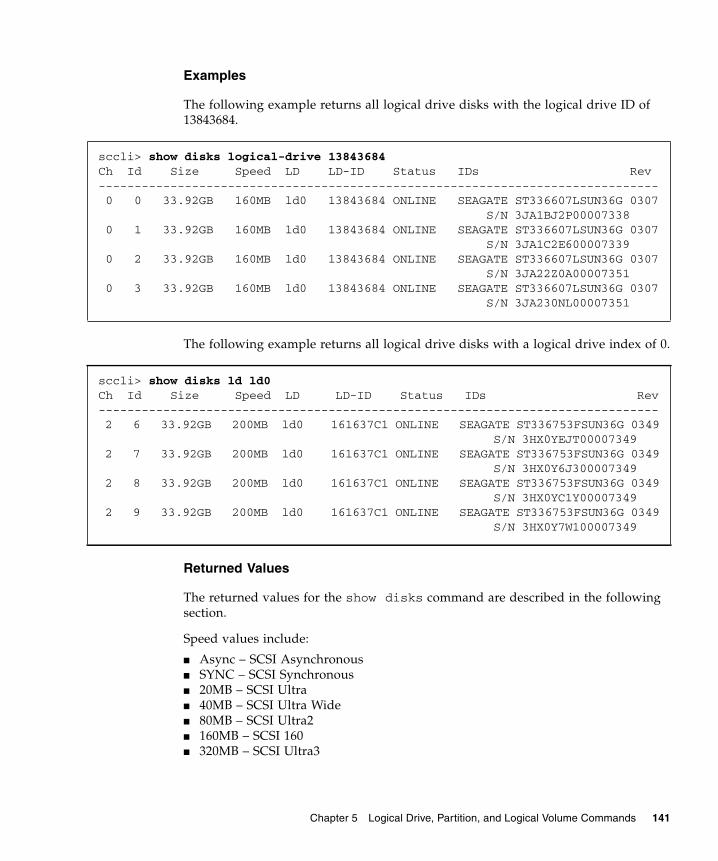
Examples
The following example returns all logical drive disks with the logical drive ID of 13843684.
The following example returns all logical drive disks with a logical drive index of 0.
Returned Values
The returned values for the show disks command are described in the following section.
Speed values include:
■ Async – SCSI Asynchronous■ SYNC – SCSI Synchronous■ 20MB – SCSI Ultra■ 40MB – SCSI Ultra Wide■ 80MB – SCSI Ultra2■ 160MB – SCSI 160■ 320MB – SCSI Ultra3
sccli> show disks logical-drive 13843684Ch Id Size Speed LD LD-ID Status IDs Rev------------------------------------------------------------------------------ 0 0 33.92GB 160MB ld0 13843684 ONLINE SEAGATE ST336607LSUN36G 0307 S/N 3JA1BJ2P00007338 0 1 33.92GB 160MB ld0 13843684 ONLINE SEAGATE ST336607LSUN36G 0307 S/N 3JA1C2E600007339 0 2 33.92GB 160MB ld0 13843684 ONLINE SEAGATE ST336607LSUN36G 0307 S/N 3JA22Z0A00007351 0 3 33.92GB 160MB ld0 13843684 ONLINE SEAGATE ST336607LSUN36G 0307 S/N 3JA230NL00007351
sccli> show disks ld ld0Ch Id Size Speed LD LD-ID Status IDs Rev------------------------------------------------------------------------------ 2 6 33.92GB 200MB ld0 161637C1 ONLINE SEAGATE ST336753FSUN36G 0349 S/N 3HX0YEJT00007349 2 7 33.92GB 200MB ld0 161637C1 ONLINE SEAGATE ST336753FSUN36G 0349 S/N 3HX0Y6J300007349 2 8 33.92GB 200MB ld0 161637C1 ONLINE SEAGATE ST336753FSUN36G 0349 S/N 3HX0YC1Y00007349 2 9 33.92GB 200MB ld0 161637C1 ONLINE SEAGATE ST336753FSUN36G 0349 S/N 3HX0Y7W100007349
Chapter 5 Logical Drive, Partition, and Logical Volume Commands 141
■ 100MB – FC 1 GB/s■ 200MB – FC 2 GB/s
Status values include:
■ Online – in good condition■ Global – global spare■ Stand-By – standby for global or local spare■ Initing – initialization in progress■ Rebuild – rebuild in progress■ New – new disk that has not been configured■ Used – contains RAID meta data■ Bad – failed disk■ Absent – disk does not exist■ Missing – configured disk is missing■ SB-Miss – configured spare drive is missing■ None – not assigned■ Good – no operation in progress
show logical-drive
Description
The show logical-drive command displays information about specified logical drives. For details on creating logical drives, see “create logical-drive” on page 131.
Caution – Any time logical drives are created or deleted, the numbering of logical drive indexes might change. After creating or deleting logical drives, issue a show logical-drive command to view an updated list of logical drive indexes. Or, use logical drive IDs, which do not change over the lifetime of the logical drive, rather than logical drive indexes. For more information, see “Logical Drive Syntax” on page 13.
Note – If no write policy is specified for the logical drive, the write policy is set to the global controller setting and “Default” displays in the Write-Policy field. To view the controller write policy, run the show cache-parameters command. For more information about the cache policy, see “set cache-parameters” on page 73.
Syntax
show logical-drive [ld-list]
142 Sun StorEdge 3000 Family CLI 2.4 User’s Guide • March 2007

Note – The abbreviation ld can be substituted for the keyword logical-drive.
Arguments
If no options are specified, all logical drives are displayed.
Examples
The following example returns all logical drive information.
The following example returns all logical drives with logical drive index numbers 0 and 1.
Returned Values
Returned values include LD index, LD ID, size (MB or GB), controller assignment, RAID level, number of disks, number of spares, number of failed disks, status, write policy type, block size (KB), and block status.
Status values include:
■ Good – no reported failures■ Good I – online initialization or expansion in progress■ Good E – offline expansion in progress
TABLE 5-17 Arguments for show logical-drive
Argument Description
ld-list Specify a list of logical drives.
sccli> show ldLD LD-ID Size Assigned Type Disks Spare Failed Status------------------------------------------------------------------------ld0 161637C1 101.00GB Primary RAID5 4 1 0 Good Write-Policy Default StripeSize 128KB
sccli> show logical-drive ld0,ld1LD LD-ID Size Assigned Type Disks Spare Failed Status------------------------------------------------------------------------ld0 250FF1DC 30MB Primary RAID5 4 2 0 Good Write-Policy Default StripeSize 128KBld1 363F38D9 67.34GB Primary RAID3 3 2 0 Good Write-Policy Default StripeSize 16KB
Chapter 5 Logical Drive, Partition, and Logical Volume Commands 143

■ Initing – initialization in progress■ Initing I – offline initialization in progress■ Incomplete – two or more drives failed■ Invalid – wrong optimization setting■ Dead – drive in a fatal fail state■ Drv Failed – drive failed■ Drv Absent – drive not detected■ Rebuilding – rebuild in progress■ P – parity check in progress■ E – expand in progress■ I – online initialization in progress■ A – adding disk in progress■ AP – adding disk paused
show logical-drives add-disk
Description
The show logical-drives add-disk command displays the status of disks that are being added to a logical drive. Returned values include LD index, LD ID, and progress. For details on the add disk command, see “add disk” on page 126.
Syntax
Note – The abbreviation ld can be substituted for the keyword logical-drive.
Examples
The following example returns the completion percentage for the disks that are being added.
show logical-drives expanding
Description
The show logical-drives expanding command displays the progress of the logical drive expansion. Returned values include LD index, LD ID, and progress. For details on expanding logical drives, see “expand” on page 135.
show logical-drives add-disk
# sccli c2t0d0 show logical-drives add-disk
144 Sun StorEdge 3000 Family CLI 2.4 User’s Guide • March 2007

Syntax
Note – The abbreviation ld can be substituted for the keyword logical-drive.
Examples
The following example returns the completion percentage for the logical drive expansion.
show logical-drives initializing
Description
The show logical-drives initializing command displays the progress of the RAID controller initialization. Returned values include LD index, LD ID, and progress.
Syntax
Note – The abbreviation ld can be substituted for the keyword logical-drive.
show logical-drives expanding
sccli> show logical-drives expandingLD LD-ID Status------------------------ld0 250FF1DC 60% complete (offline)
show logical-drives initializing
Chapter 5 Logical Drive, Partition, and Logical Volume Commands 145

Examples
The following example returns the completion percentage of the RAID controller for all logical drives.
show logical-drives logical volume
Description
The show logical-drives logical-volume command displays information for all logical drives in a specified logical volume.
Caution – Any time logical volumes are created or deleted, the numbering of logical volume indexes might change. After creating or deleting logical volumes, issue a show logical-volumes command to view an updated list of logical volume indexes. Or, use logical volume IDs, which do not change over the lifetime of the logical volume, rather than logical volume indexes. For more information, see “Logical Volume Syntax” on page 14.
Note – If no write policy is specified for the logical drive, the write policy is set to the global controller setting and “Default” displays in the Write-Policy field. To view the controller write policy, run the show cache-parameters command. For more information about the cache policy, see “set cache-parameters” on page 73.
Syntax
Note – The abbreviation ld can be substituted for the keyword logical-drive. The abbreviation lv can be substituted for the keyword logical-volume.
sccli> show ld initializingLD LD-ID Status------------------------ld1 59839F65 10% complete (online)
show logical-drives logical-volume {lv-index | lv-id}
146 Sun StorEdge 3000 Family CLI 2.4 User’s Guide • March 2007

Arguments
Examples
The following example returns all logical drives with the logical volume ID of 12345678.
The following example shows all logical drives in the logical volume with the ID of 0.
Returned Values
Returned values include LD index, LD ID, RAID level, size (GB), status, number of disks, number of spares, and number of failed disks.
Status values include:
■ Good – in good condition■ Initing – the logical drive is initializing■ Incomplete – two or more drives failed■ Invalid – wrong optimization setting■ Drv Failed – drive failed■ Drv Absent – drive not detected
TABLE 5-18 Arguments for show logical-drives logical volume
Argument Description
lv-index Show specific drives in a logical volume. The index number is generated from the Sun StorEdge CLI. Use the show logical-volumes command to find the number.
lv-id Show specific drives in a logical volume. The ID number is generated from the Sun StorEdge CLI. Use the show logical-volumes command to find the number
# sccli c2t0d0 show logical-drives logical-volume 12345678
sccli> show ld lv lv0LD LD-ID Size Assigned Type Disks Spare Failed Status------------------------------------------------------------------------ld1 363F38D9 67.34GB Primary RAID3 3 2 0 Good Write-Policy Default StripeSize 16KB
Chapter 5 Logical Drive, Partition, and Logical Volume Commands 147

show logical-drives parity-check
Description
The show logical-drives check-parity command displays the status of a parity check being performed on a logical drive. Returned values include LD index, LD ID, and progress. To cancel the parity check, use the abort parity-check command. For details, see “abort parity-check” on page 125.
Syntax
Note – The abbreviation ld can be substituted for the keyword logical-drive.
Examples
The following example returns the percent complete for the parity check for logical drive 0.
For details on the check parity command, see “check parity” on page 128.
show logical-drives parity-check
sccli> check parity ld0sccli> show ld parity-checkLD LD-ID Status------------------------ld0 627D800A 2% complete
148 Sun StorEdge 3000 Family CLI 2.4 User’s Guide • March 2007

show logical-drives rebuilding
Description
The show logical-drives rebuilding command displays the status for all logical drives being rebuilt. Returned values include LD index, LD ID, and progress. To cancel the rebuild, use the abort rebuild command. For details, see “abort rebuild” on page 126.
Syntax
Note – The abbreviation ld can be substituted for the keyword logical-drive.
Examples
The following example returns the rebuilding process percent complete for the logical drive.
show media-check
Description
The show media-check command displays the progress of a media check. To cancel the media check, use the abort media-check command. For details, see “abort media-check” on page 124.
Note – The front-panel LEDs for the drives being checked will blink until the media check is finished or aborted. For more information about LEDs, refer to the Sun StorEdge 3000 Family Installation, Operation, and Service Manual for your array.
Syntax
show logical-drives rebuilding
# sccli c2t0d0 show logical-drives rebuilding
show media-check
Chapter 5 Logical Drive, Partition, and Logical Volume Commands 149

Examples
The following example shows the progress of the media check.
show stripe-size-list
Description
The show stripe-size list command displays the valid stripe block size list for the specified RAID level. To set the stripe size for an individual logical drive, use the create logical-drive command. For details, see “create logical-drive” on page 131.
Note – Once data is written to logical drives, the only way to change the stripe size is to back up all data to another location, delete all logical configurations of drives, reconfigure the logical drive with the stripe size, and reboot the array.
Syntax
Arguments
sccli> show media-check Ch ID Iteration Status------------------------------ 2 6 0 2% complete 2 7 0 2% complete 2 8 0 2% complete 2 9 0 2% complete
show stripe-size-list raid-level
TABLE 5-19 Arguments for show stripe-size-list
Argument Description
raid-level Specify the RAID level to display the corresponding stripe block size. Valid values: raid0, raid1, raid3, raid5.
150 Sun StorEdge 3000 Family CLI 2.4 User’s Guide • March 2007
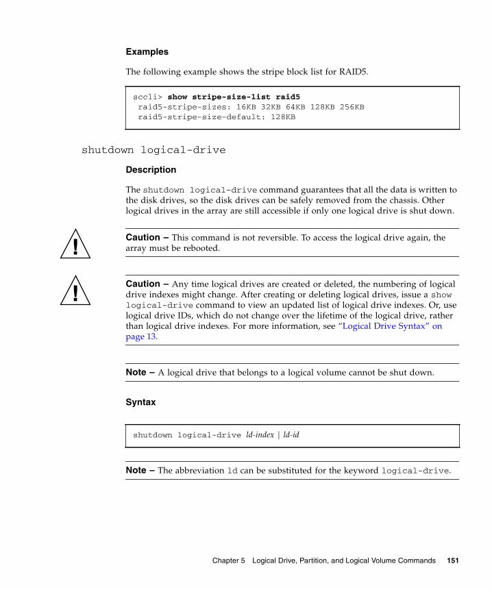
Examples
The following example shows the stripe block list for RAID5.
shutdown logical-drive
Description
The shutdown logical-drive command guarantees that all the data is written to the disk drives, so the disk drives can be safely removed from the chassis. Other logical drives in the array are still accessible if only one logical drive is shut down.
Caution – This command is not reversible. To access the logical drive again, the array must be rebooted.
Caution – Any time logical drives are created or deleted, the numbering of logical drive indexes might change. After creating or deleting logical drives, issue a show logical-drive command to view an updated list of logical drive indexes. Or, use logical drive IDs, which do not change over the lifetime of the logical drive, rather than logical drive indexes. For more information, see “Logical Drive Syntax” on page 13.
Note – A logical drive that belongs to a logical volume cannot be shut down.
Syntax
Note – The abbreviation ld can be substituted for the keyword logical-drive.
sccli> show stripe-size-list raid5 raid5-stripe-sizes: 16KB 32KB 64KB 128KB 256KB raid5-stripe-size-default: 128KB
shutdown logical-drive ld-index | ld-id
Chapter 5 Logical Drive, Partition, and Logical Volume Commands 151

Arguments
Examples
The following example shuts down the logical drive and then shows the status of that drive.
unconfigure local-spare
Description
The unconfigure local-spare command removes a local spare disk as a dedicated spare disk for the specified logical drive.
Caution – Any time logical drives are created or deleted, the numbering of logical drive indexes might change. After creating or deleting logical drives, issue a show logical-drive command to view an updated list of logical drive indexes. Or, use logical drive IDs, which do not change over the lifetime of the logical drive, rather than logical drive indexes. For more information, see “Logical Drive Syntax” on page 13.
TABLE 5-20 Arguments for shutdown logical-drive
Argument Description
ld-index Specify the logical drive index number. For example, ld3.
ld-id Specify the logical drive ID. For example, 71038221.
sccli> shutdown logical-drive ld3WARNING: This is a potentially dangerous operation.The logical drive will be placed permanently offline.A controller reset will be required to bring it back online.Are you sure? yessccli: ld3: offlined logical drivesccli> show logical-driveLD LD-ID Size Assigned Type Disks Spare Failed Status-------------------------------------------------------------------------ld0 0043BF50 101.01GB Primary RAID0 3 0 0 Goodld1 025E42E1 33.67GB Primary RAID1 2 3 0 Goodld2 05CC1F19 67.34GB Primary NRAID 2 0 0 Goodld3 52AD5DEB 33.67GB Primary NRAID 1 0 0 ShutDown
152 Sun StorEdge 3000 Family CLI 2.4 User’s Guide • March 2007

Syntax
Arguments
Examples
The following example unconfigures disk drive ID 5 on channel 2 as a local spare for the logical drive with index number 2.
The following example unconfigures disk drive ID 5 on channel 2 as a local spare for the logical drive with ID 2C33AAEA.
Partition CommandsThe following commands are explained in this section:
■ configure partition■ map partition■ show lun-maps■ show partitions■ unmap partition
unconfigure local-spare disk [ld-index | ld-id]
TABLE 5-21 Arguments for unconfigure local-spare
Argument Description
disk Specify the disk to unconfigure. For example, specify the disk with target ID 1 on channel 2 as 2.1.
ld-index Specify the logical drive index number. For example, ld3.
ld-id Specify the logical drive ID. For example, 71038221.
# sccli c2t0d0 unconfigure local-spare 2.5 ld2
# sccli c2t0d0 unconfigure local-spare 2.5 2C33AAEA
Chapter 5 Logical Drive, Partition, and Logical Volume Commands 153

configure partition
Description
The configure partition command specifies how much disk space to assign to the partition or deletes a specified partition. When a logical drive or logical volume is created, it is automatically assigned to partition 0.
Syntax
Arguments
Note – All device capacity is displayed in powers of 1024. For details, see “Device Capacity” on page 15.
Note – Changes to a partition cause the next-higher-numbered partition to shrink or grow. Any change in the size of one partition causes the dimensions of the partition next to it to change as well, invalidating whatever data might be stored on both partitions. Before implementing a new partition layout, the layout is displayed and the user is warned that data in the old partitions will be lost. The user is prompted to continue.
configure partition partition [size | delete]
TABLE 5-22 Arguments for configure partition
Argument Description
partition ID Specify a combination of LD-ID/LV-ID and partition-number in XXXXXXXX-PP format where XXXXXXXX represents the Logical Drive/Volume ID, or a combination of LD/LV Index and partition number in ld{X}/lv{X}-PP format where LD/LV Index is the Logical Drive/Volume Index number. PP is a two-digital hexidecimal number that represents the partition number.
size Specify the partition size in MB, such as 4000MB. To delete a partition, specify a size of 0. Or, use the delete keyword.
delete To delete a partition, specify the delete keyword. All partitions in the logical drive or logical volume must be unmapped for this argument to take effect.
154 Sun StorEdge 3000 Family CLI 2.4 User’s Guide • March 2007

Examples
The following example creates a partition for a logical drive with a logical drive index number of 2, partition number of 2, and partition size of 4000 Mbyte, and leaves the remaining capacity for the next partition.
The following example creates a partition for a logical drive with a logical drive ID of 1D2F34AA, partition number of 2, and partition size of 4000 Mbyte, and leaves the remaining capacity for the next partition.
This example deletes a partition from logical drive 0.
map partition
Description
The map partition command maps a partition to the specified host channel, target, and LUN on the specified controller. To review host channel assignments, run the show channels command. For more information, see “show channels” on page 113. To review LUN maps, see “show lun-maps” on page 158.
Note – In redundant-controller configurations, the specified channel and target must be valid on the controller to which the specified logical drive or volume is assigned. For example, to map a partition to the primary controller in a FC array, the logical drive or logical volume must be assigned to a primary channel ID.
Note – A maximum of 32 partitions per logical drive can be created. And, a maximum of 64 host WWN entries can be created.
# sccli c2t0d0 configure partition ld2-02 4000MB
# sccli c2t0d0 configure partition 1D2F34AA-02 4000MB
# sccli c2t0d0 configure partition ld0-0 delete
Chapter 5 Logical Drive, Partition, and Logical Volume Commands 155

Syntax
To map a partition, use the following syntax:
Or, to map a partition, use the following syntax:
Arguments
map partition-id channel channel-number target SCSI-id lun lun-number [wwpn | host-id][read-only | read-write] [include | exclude] [mask] [name]
map partition-id channel.target.lun [wwpn | host-id][read-only | read-write] [include | exclude] [mask] [name]
TABLE 5-23 Arguments for map partition
Argument Description
partition ID Specify a combination of LD-ID/LV-ID and partition-number in XXXXXXXX-PP format where XXXXXXXX represents the Logical Drive/Volume ID, or a combination of LD/LV Index and partition number in ld{X}/lv{X}-PP format where LD/LV Index is the Logical Drive/Volume Index number. PP is a two-digital hexidecimal number that represents the partition number. Valid partition-IDs for a logical drive, for example, are 3C2B1111-01 or ld2-03. Valid partition-IDs for a logical volume, for example, are 205FB9AC-01 or lv2-03.
channel ch Specify a host channel number between 0 and 7.
target target Specify a host channel target number between 0 and 126.
lun lun Specify a host channel LUN number.
channel.target.lun Specify the channel, target, and LUN to map. For example, 4.1.2 represents physical channel 4, target ID 1, logical unit number 2.
wwpn Sun StorEdge 3000 family FC and SATA devices only. Specify a worldwide port name (WWPN) to map to the host bus adapter with the specified WWPN. To review the available WWPN values, run the show port-wwn command. For details, see “show port-wwn” on page 29.
host-id Specify the host-ID of the corresponding WWPN to map to the host bus adapter. To review the available WWPN values, run the show port-wwn command. For details, see “show port-wwn” on page 29.
156 Sun StorEdge 3000 Family CLI 2.4 User’s Guide • March 2007

Examples
The following example maps partition 0 of the logical drive with index number 2 to LUN 0 of channel 1 on ID 112 and 113.
The following example maps partition 0 of the logical drive with ID 2D1A2222 to LUN 0 of channel 1 on ID 112.
The following example maps partition 0 of the logical volume with index number 2 to LUN 0 of channel 1 on ID 112. It sets access permission to read/write, includes the filter so all hosts can access the LUN, and names it “sabre-2.”
[read-only | read-write]
Sun StorEdge 3000 family FC and SATA devices only. To specify the access mode, which assigns Read-Only or Read/Write privileges, type read-only or read-write.
[include | exclude] Sun StorEdge 3000 family FC and SATA devices only. Specify include to grant LUN access to the host identified by the WWN and WWN Mask. Type exclude to deny the identified host LUN access. If no host has been granted access to the selected LUN (by specifying include), all hosts can access that LUN. Once any host is granted access to a LUN, only hosts with explicit access (with include specified) can access that LUN.
mask Sun StorEdge 3000 family FC and SATA devices only. Specify the WWN Mask. LUN access is granted based on the host identified by WWN and mask.
name Sun StorEdge 3000 family FC and SATA devices only. To set a name for the filter, type the name you want to use
# sccli c2t0d0 map ld2-00 channel 1 target 112 lun 0
# sccli c2t0d0 map 2D1A2222-00 channel 1 target 112 lun 0
# sccli c2t0d0 map lv2-00 1.112.0 read-write include sabre-2
TABLE 5-23 Arguments for map partition (Continued)
Argument Description
Chapter 5 Logical Drive, Partition, and Logical Volume Commands 157

show lun-maps
Description
The show lun-maps command shows all partitions mapped to a specified host channel. Returned values include host channel, target ID, LUN ID, logical volume or logical drive index, partition ID, controller assignment, and worldwide name (WWN) filters for the LUNs.
Sun StorEdge 3000 family FC and SATA arrays only. This command additionally shows mask information, access (RW for read/write or RO for ready only permission), type (I for include or E for exclude), and name.
Syntax
Arguments
Examples
The following example shows all partitions mapped to host channel 1 and 3.
The following example shows all partitions mapped to the host channels in a Sun StorEdge 3510 FC array.
show lun-maps [channel host-channel-list]
TABLE 5-24 Arguments for show lun-maps
Argument Description
host-channel-list Specify the LUN format. Use the format {n}[,…{m}] or a range format “{n}-{m}” or {n}[,…{p}-{m}].Valid channel numbers include 0–7 or 0–5 depending on the hardware configuration.
sccli> show lun-maps channel 1-3Ch Tgt LUN ld/lv ID-Partition Assigned Filter Map-------------------------------------------------------------- 1 0 0 ld0 64D138EC-00 Primary 3 1 0 ld1 3C67B2FD-00 Secondary
158 Sun StorEdge 3000 Family CLI 2.4 User’s Guide • March 2007

show partitions
Description
The show partitions command displays information about all disk partitions, or just those partitions allocated from the specified logical volumes or logical drives. Returned values include logical volume or logical drive index, logical volume or logical drive ID, partition number, offset (GB), and size (GB).
Syntax
Arguments
sccli> show lun-mapsCh Tgt LUN ld/lv ID-Partition Assigned Filter Map Access Type Mask Name--------------------------------------------------------------------0 40 0 ld2 3F1561F1-00 Primary 210000E08B101256 {sabre-2} RW I FFFFFFFFFFFFFFFF0 40 0 ld0 20CEAE10-00 Primary 210100E08B301256 {sabre-1} RW I FFFFFFFFFFFFFFFF1 42 0 ld1 15F4EEA7-00 Secondary1 42 1 ld3 029B14A2-00 Secondary
show partitions [{lv-index | lv-id} | {ld-index | ld-id}]
TABLE 5-25 Arguments for show partitions
Argument Description
lv-index Specify a comma-separated list of logical volume indexes, for example, lv0,lv1,lv2.
ld-index Specify the logical drive index number. For example, ld3.
lv-id Specify a logical volumes using an eight-digit hexadecimal logical volume ID, for example, 3C24554F.
ld-id Specify the logical drive ID. For example, 71038221.
Chapter 5 Logical Drive, Partition, and Logical Volume Commands 159

Examples
The following example shows the logical drive partition table for the logical drive with the ID 161637C1.
The following example shows the logical volume partition table for the logical volume with index number 0.
unmap partition
Description
The unmap partition command unmaps a partition. Use the appropriate syntax depending on the target you want to unmap. To view the current partitions, use the show partitions or show lun-maps command. For details, see “show partitions” on page 159 or “show lun-maps” on page 158.
You can unmap a partition currently mapped to the specified channel.target.lun address. If a host worldwide port name (WWPN) or alias (previously defined using create host-wwn-name) is specified, the specified host LUN mapping is removed without affecting other host LUN maps on the same host LUN.
Syntax
To unmap a partition using a channel, target, LUN address, use the following syntax.
You can unmap a specified partition from any LUNs to which its mapped, or if channel is specified, from LUNs on the specified channel.
sccli> show partitions logical-drive 161637c1LD/LV ID-Partition Size-------------------------------------ld0-00 161637C1-00 101.00GB
sccli> show part lv0LD/LV ID-Partition Size-------------------------------lv0-00 02CE9894-00 4.00GB
unmap partition channel.target.lun [wwpn | host-wwn-name]
160 Sun StorEdge 3000 Family CLI 2.4 User’s Guide • March 2007

To unmap a partition from a specified partition or channel, use the following syntax.
Arguments
unmap partition partition-id [channel]
TABLE 5-26 Arguments for unmap partition
Argument Description
partition-id Specify a combination of LD-ID/LV-ID and partition-number in XXXXXXXX-PP format where XXXXXXXX represents the Logical Drive/Volume ID, or a combination of LD/LV Index and partition number in ld{X}/lv{X}-PP format where LD/LV Index is the Logical Drive/Volume Index number. PP is a two-digital hexidecimal number that represents the partition number. Valid partition IDs for a logical drive, for example, are 3C2B1111-01 or ld2-03. Valid partition IDs for a logical volume, for example, are 205FB9AC-01 or lv2-03.
channel Specify a host channel number between 0 and 7 when unmapping a specific partition from only one channel.
channel.target.lun Specify the channel, target, and LUN to unmap. This must be on the same controller as the logical volume or the logical drive that you are unmapping. Specify a host channel number between 0 and 7 when unmapping a specific partition from only one channel. Specify a host channel SCSI target number between 0 and 126. Since a host channel can have multiple SCSI IDs, the user can map the partition to multiple SCSI IDs of a host channel. Use the SCSI-ID-list format: {p}[,…{q}[,…{n}]]. Specify a host channel LUN number. For example, 4.1.2 represents physical channel 4, target ID 1, logical unit number 2.
wwpn Sun StorEdge 3000 family FC and SATA devices only. Specify a worldwide port name (WWPN) to unmap from the host bus adapter with the specified WWPN. To review the available WWPN values, run the show port-wwn command. For details, see “show port-wwn” on page 29.
host-wwn-name Sun StorEdge 3000 family FC and SATA devices only. Specify a host name to unmap from the host bus adapter with the specified worldwide name (WWN).
Chapter 5 Logical Drive, Partition, and Logical Volume Commands 161

Examples
The following example unmaps the partition assigned to host channel, target ID 0, LUN 3.
The following example unmaps the partition from partition ID 0A7F8942-00.
sccli> show lun-mapsCh Tgt LUN ld/lv ID-Partition Assigned Filter Map-------------------------------------------------------------- 1 0 0 ld0 13843684-00 Primary 1 0 1 ld1 295AB786-00 Primary 1 0 2 ld2 0A7F8942-00 Primary 1 0 3 ld2 0A7F8942-00 Primarysccli> unmap partition 1.0.3sccli> show lun-mapsCh Tgt LUN ld/lv ID-Partition Assigned Filter Map-------------------------------------------------------------- 1 0 0 ld0 13843684-00 Primary 1 0 1 ld1 295AB786-00 Primary 1 0 2 ld2 0A7F8942-00 Primary
sccli> unmap partition 0A7F8942-00 1
162 Sun StorEdge 3000 Family CLI 2.4 User’s Guide • March 2007

Logical Volume CommandsThe following commands are explained in this section:
■ create logical-volume■ delete logical-volume■ set logical-volume■ show logical-volumes
create logical-volume
Description
Note – Logical volumes are unsuited to some modern configurations such as Sun Cluster environments, and do not work in those configurations. Use logical drives instead. For more information about logical drives, see “create logical-drive” on page 131.
The create logical-volume command creates a logical volume from the specified logical drives on the specified controller. The logical drives used to create the logical volume must not already be mapped to any host channels. Be sure to specify the secondary keyword if the underlying logical drives are mapped to the secondary controller.
Caution – Any time logical volumes are created or deleted, the numbering of logical volume indexes might change. After creating or deleting logical volumes, issue a show logical-volumes command to view an updated list of logical volume indexes. Or, use logical volume IDs, which do not change over the lifetime of the logical volume, rather than logical volume indexes. For more information, “Logical Volume Syntax” on page 14.
Syntax
create logical-volume ld-list [assignment] [write-policy]
Chapter 5 Logical Drive, Partition, and Logical Volume Commands 163

Arguments
Examples
The following example creates a logical volume using ld0 and ld2 and assigns it to the primary controller.
The following example creates a logical volume using IDs 2378FDED, 7887DDAB and assigns it to the secondary controller.
delete logical-volume
Description
The delete logical-volume command deletes the specified logical volumes.
Caution – Any time logical volumes are created or deleted, the numbering of logical volume indexes might change. After creating or deleting logical volumes, issue a show logical-volumes command to view an updated list of logical volume indexes. Alternatively, use logical volume IDs, which do not change over the lifetime of the logical volume, rather than logical volume indexes. For more information, see “Logical Volume Syntax” on page 14.
TABLE 5-27 Arguments for create logical-volume
Argument Description
ld-list A comma separated list of logical drive indexes, for example, ld0,ld1,ld2, or a list of logical drive identifiers, such as, 71038221.
assignment Specify the controller assignment for the logical volume. If no value is specified, the logical volume is assigned to the primary controller by default. Valid values: primary, secondary.
write-policy Set the write policy for the logical volume. Valid values: write-back, write-through. If you do not specify a write policy, the logical volume uses the write policy specified for the controller. If the write policy changes for the controller, the write policy automatically changes for the logical volume as well. To set the controller write policy, use the set cache-parameters command. For details, see “set cache-parameters” on page 73.
# sccli c2t0d0 create logical-volume ld0,ld2 primary
# sccli c2t0d0 create logical-volume 2378FDED,7887DDAB secondary
164 Sun StorEdge 3000 Family CLI 2.4 User’s Guide • March 2007

Note – Before you can delete a logical volume, you must unmap all assigned LUNs. To review LUN maps, see “show lun-maps” on page 158.
Syntax
Arguments
Examples
The following example deletes the logical volume with the logical volume index number 2.
The following example deletes the logical volume with the logical volume ID number 3C24554F.
set logical-volume
Description
The set logical-volume command sets the write policy and controller assignment for the specified logical volume. Before using this command, you must create a logical volume. For more details, see “create logical-volume” on page 163.
delete logical-volume {lv-index | lv-id}
TABLE 5-28 Arguments for delete logical-volume
Argument Description
lv-index Specify a comma-separated list of logical volume indexes, for example, lv0,lv1,lv2.
lv-id Specify a logical volumes using an eight-digit hexadecimal logical volume ID; for example, 3C24554F.
# sccli c2t0d0 delete logical-volume lv2
# sccli c2t0d0 delete logical-volume 3C24554F
Chapter 5 Logical Drive, Partition, and Logical Volume Commands 165

Note – Logical volumes are unsuited to some modern configurations such as Sun Cluster environments, and do not work in those configurations. Use logical drives instead. For more information about logical drives, see “create logical-drive” on page 131.
Syntax
Arguments
Examples
The following example sets write policy for logical volume 4 to write-back.
set logical-volume {lv-index | lv-id} [assignment] [write-policy]
TABLE 5-29 Arguments for set logical-volume
Argument Description
lv-index Set specific drives in a logical volume. The index number is generated from the Sun StorEdge CLI. Use the show logical-volumes command to find the number.
lv-id Set specific drives in a logical volume. The ID number is generated from the Sun StorEdge CLI. Use the show logical-volumes command to find the number.
write-policy Set the write policy for the logical volume. Valid values: write-back, write-through, default. If you do not specify a write-policy, or if you specify default, the logical volume uses the write-policy specified for the controller. If the write policy changes for the controller, the write policy automatically changes for the logical volume as well. To set the controller write policy, use the set cache-parameters command. For details, see “set cache-parameters” on page 73.
assignment Specify the controller assignment for the logical volume. If no value is specified, the logical volume is assigned to the primary controller by default. Valid values: primary, secondary.
set logical-volume lv4 write-back
166 Sun StorEdge 3000 Family CLI 2.4 User’s Guide • March 2007

show logical-volumes
Description
The show logical-volumes command displays information about all, or a specified list, of logical volumes. Returned values include LV index, LV ID, logical volume count, LD ID list, size (Mbyte or Gbyte), write policy, and assignment information. For details on creating logical volumes, see “create logical-volume” on page 163.
Caution – Any time logical volumes are created or deleted, the numbering of logical volume indexes might change. After creating or deleting logical volumes, issue a show logical-volumes command to view an updated list of logical volume indexes. Or, use logical volume IDs, which do not change over the lifetime of the logical volume, rather than logical volume indexes. For more information, “Logical Volume Syntax” on page 14.
Note – If no write policy is specified for the logical volume, the write policy is set to the global controller setting and “Default” displays in the Write-Policy field. To view the controller write policy, run the show cache-parameters command. For more information about the cache policy, see “set cache-parameters” on page 73.
Note – All device capacity is displayed in powers of 1024. For details, see “Device Capacity” on page 15.
Syntax
Arguments
If no arguments are specified, all logical volumes are displayed.
show logical-volumes lv-list
TABLE 5-30 Arguments for show logical-volumes
Argument Description
lv-list Specify a list of logical volumes.
Chapter 5 Logical Drive, Partition, and Logical Volume Commands 167

Examples
The following example returns all logical volume information.
The following example returns all logical volumes with logical volume index numbers 0 and 2.
# sccli 206.111.111.111 show logical-volumessccli: selected se3000://206.111.111.111:58632 [SUN StorEdge 3510 SN#000002]LV LV-ID Size Assigned Write-Policy LDs----------------------------------------------------------------lv0 43DBA866 13.67GB Primary Default 2 ld1,ld2
# sccli c2t0d0 show logical-volumes lv0,lv2LV LV-ID Size Assigned LDs-----------------------------------------lv0 02CE9894 4.00GB Primary 2 ld0,ld1lv2 02CE9894 4.00GB Primary 2 ld0,ld1
168 Sun StorEdge 3000 Family CLI 2.4 User’s Guide • March 2007

CHAPTER 6
Firmware Show and Download Commands
This chapter provides the firmware, disk drive, SCSI Enclosure Services (SES), SCSI Accessed Fault-Tolerant Enclosure (SAF-TE), programmable logic device (PLD), and serial ATA (SATA) router and path controller show and download commands. Topics covered in this chapter include:
■ “Show Commands” on page 169■ “Download Commands” on page 175
Note – To prevent unauthorized access to administrative functions of the RAID controller, the Sun StorEdge CLI requires superuser or system administrator privileges for inband access, and uses the controller password to authorize users of the out-of-band interface.
Show CommandsThe following commands are explained in this section:
■ show safte-device■ show sata-mux■ show sata-router■ show ses-devices
169

show safte-device
Description
Sun StorEdge 3000 family SCSI devices only. The show safte-device command displays information returned by the SCSI Accessed Fault-Tolerant Enclosure (SAF-TE) device embedded in SCSI LVD RAID enclosures or JBODs. When this command is issued to an LVD SCSI RAID array with one or more expansion chassis attached, the output includes one line for the RAID chassis and one line for each expansion chassis, since each enclosure contains a separate SAF-TE device.
The output includes the channel and target ID of the SAF-TE device, the serial number of the chassis in which it is installed, the vendor and product IDs (an A indicates a RAID device and an D indicates an expansion unit or JBOD), SAF-TE firmware revision, and the SAF-TE firmware package revision, which refers to firmware for other microprocesses in the chassis that are managed by the SAF-TE processor.
Syntax
Examples
The following example shows the SAF-TE device information for a Sun StorEdge 3310 SCSI array.
The following example shows the SAF-TE device information for a Sun StorEdge 3120 SCSI array.
show safte-device
sccli> show safte-deviceCh Id Chassis Vendor Product ID Rev Package--------------------------------------------------------- 0 14 002A4C SUN StorEdge 3310 A 1170 1170
sccli> show safte-device Id Chassis Vendor Product ID Rev Package------------------------------------------------------ 5 0064CA SUN StorEdge 3120 D 1170 1170
170 Sun StorEdge 3000 Family CLI 2.4 User’s Guide • March 2007

show sata-mux
Description
The show sata-mux command shows the SATA multiplexer (MUX) board information for all drives. Each drive has one MUX board. The information for the MUX board includes the channel number and ID of the drive attached to the MUX board, MUX board serial number, MUX board type (active-passive or active-active), path controller (PC150) firmware revision number, and PC150 boot revision.
Syntax
Examples
The following example shows the MUX board information for the drives attached to the specified device. When no serial number has been programmed for the MUX board, n/a displays in the MUX-SN column.
show sata-mux
Chapter 6 Firmware Show and Download Commands 171
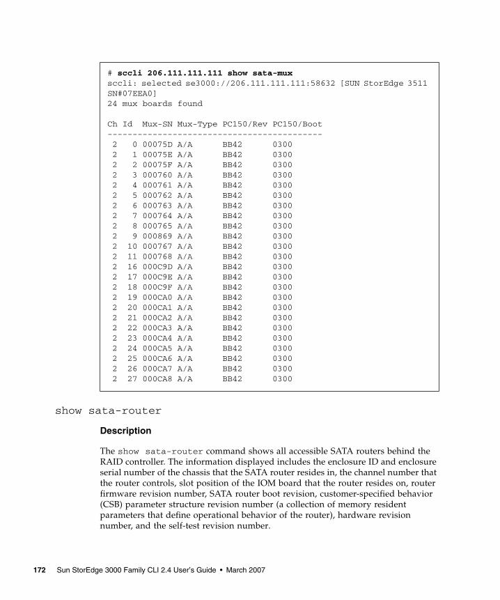
show sata-router
Description
The show sata-router command shows all accessible SATA routers behind the RAID controller. The information displayed includes the enclosure ID and enclosure serial number of the chassis that the SATA router resides in, the channel number that the router controls, slot position of the IOM board that the router resides on, router firmware revision number, SATA router boot revision, customer-specified behavior (CSB) parameter structure revision number (a collection of memory resident parameters that define operational behavior of the router), hardware revision number, and the self-test revision number.
# sccli 206.111.111.111 show sata-muxsccli: selected se3000://206.111.111.111:58632 [SUN StorEdge 3511 SN#07EEA0]24 mux boards found
Ch Id Mux-SN Mux-Type PC150/Rev PC150/Boot------------------------------------------- 2 0 00075D A/A BB42 0300 2 1 00075E A/A BB42 0300 2 2 00075F A/A BB42 0300 2 3 000760 A/A BB42 0300 2 4 000761 A/A BB42 0300 2 5 000762 A/A BB42 0300 2 6 000763 A/A BB42 0300 2 7 000764 A/A BB42 0300 2 8 000765 A/A BB42 0300 2 9 000869 A/A BB42 0300 2 10 000767 A/A BB42 0300 2 11 000768 A/A BB42 0300 2 16 000C9D A/A BB42 0300 2 17 000C9E A/A BB42 0300 2 18 000C9F A/A BB42 0300 2 19 000CA0 A/A BB42 0300 2 20 000CA1 A/A BB42 0300 2 21 000CA2 A/A BB42 0300 2 22 000CA3 A/A BB42 0300 2 23 000CA4 A/A BB42 0300 2 24 000CA5 A/A BB42 0300 2 25 000CA6 A/A BB42 0300 2 26 000CA7 A/A BB42 0300 2 27 000CA8 A/A BB42 0300
172 Sun StorEdge 3000 Family CLI 2.4 User’s Guide • March 2007

Syntax
Examples
The following example shows the data returned from a redundant configuration. Two routers are assigned to the same chassis in a redundant configuration. (The Encl-SN column displays the same chassis serial number for both routers.)
In the following example, no valid path exists on the lower router, so n/a displays to indicate that no data was returned.
show ses-devices
Description
Sun StorEdge 3000 family FC and SATA devices only. The show ses-devices command displays a list of SCSI Enclosure Services (SES) devices visible to the selected array controller or JBOD. The output includes the channel and target ID of the SES device, serial number of the chassis in which it is installed, vendor and product IDs, SES firmware revision, programmable logic device (PLD) firmware revision, worldwide node name (WWNN), worldwide port name (WWPN) for the device, and the loop location.
In redundant configurations, SES devices are installed in pairs in a single chassis. Therefore, two devices show the same chassis serial number. It is important to ensure the SES firmware and PLD revisions are consistent for SES devices installed
show sata-router
sccli> show sata-routerEncl-ID Encl-SN Ch Slot Rev Boot-rev CSB HW-rev ST-rev-------------------------------------------------------------0 07ECC0 2 upper DP0553 0548 0500 11 05520 07ECC0 3 lower DP0553 0548 0500 11 0552
# sccli 206.6.180.20 show sata-routersccli: selected se3000://206.1.111.11:58632 [SUN StorEdge 3511 SN#07ECDF]Encl-ID Encl-SN Ch Slot Rev Boot-rev CSB HW-rev ST-rev------------------------------------------------------------0 07ECDF 2 upper DP0548 0509 0500 00 05520 07ECDF 3 lower n/a n/a n/a n/a n/a
Chapter 6 Firmware Show and Download Commands 173
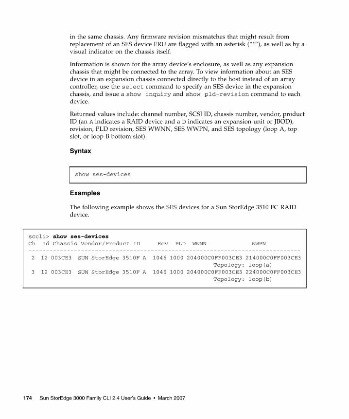
in the same chassis. Any firmware revision mismatches that might result from replacement of an SES device FRU are flagged with an asterisk (“*”), as well as by a visual indicator on the chassis itself.
Information is shown for the array device’s enclosure, as well as any expansion chassis that might be connected to the array. To view information about an SES device in an expansion chassis connected directly to the host instead of an array controller, use the select command to specify an SES device in the expansion chassis, and issue a show inquiry and show pld-revision command to each device.
Returned values include: channel number, SCSI ID, chassis number, vendor, product ID (an A indicates a RAID device and a D indicates an expansion unit or JBOD), revision, PLD revision, SES WWNN, SES WWPN, and SES topology (loop A, top slot, or loop B bottom slot).
Syntax
Examples
The following example shows the SES devices for a Sun StorEdge 3510 FC RAID device.
show ses-devices
sccli> show ses-devicesCh Id Chassis Vendor/Product ID Rev PLD WWNN WWPN------------------------------------------------------------------------------ 2 12 003CE3 SUN StorEdge 3510F A 1046 1000 204000C0FF003CE3 214000C0FF003CE3 Topology: loop(a) 3 12 003CE3 SUN StorEdge 3510F A 1046 1000 204000C0FF003CE3 224000C0FF003CE3 Topology: loop(b)
174 Sun StorEdge 3000 Family CLI 2.4 User’s Guide • March 2007

Download CommandsThe following commands are explained in this section:
■ download controller-firmware■ download disk-firmware■ download pld-hardware■ download safte-firmware■ download sata-path-controller-firmware■ download sata-router-firmware■ download ses-firmware
Caution – All download commands are potentially dangerous.
Caution – In redundant-controller configurations, download commands affect all LUNs on both controllers. After running a download command, run the select command to reselect the device.
Caution – Stop the Configuration Service agent if it is running.
Note – Although redundant-controller configurations support live firmware upgrades using its failover capability, the failover operation itself might cause warning messages to be displayed on the console or system log. These messages can be ignored.
Note – If the download firmware files are not under the same directory as the Sun StorEdge CLI, you must specify the full path.
download controller-firmware
Description
The download controller-firmware command downloads firmware to the RAID controller. Before the command is executed, the firmware file is checked to ensure that it is appropriate for the target device. In a dual-controller configuration, the failover capability of the redundant controller pair is used to activate the new
Chapter 6 Firmware Show and Download Commands 175

firmware without requiring the array to be shut down in what is known as a live upgrade or hot firmware download operation. In a single-controller configuration, the new firmware is activated by resetting the controller.
If the -r or --reset option is specified, the controllers are always reset instead of performing a live upgrade. This option is faster and is recommended when a live upgrade is not required.
Caution – All reset commands cause the array to stop responding to I/O requests from the host for a period of time. This might result in data loss unless all I/O activity is suspended by halting all applications that are accessing the array, and unmounting any file systems that are mounted from the array. In redundant-controller configurations, these commands affect all LUNs on both controllers.
Syntax
Arguments
Examples
The following example downloads firmware to the RAID controller.
download controller-firmware filename [-r | --reset]
TABLE 6-1 Arguments for download controller-firmware
Argument Description
filename Specify the firmware file name for the file that you want to download.
[-r | --reset] Reset the controller after the download completes.
sccli> download controller-firmware SUN411G-3510.binsccli: selected se3000://199.249.246.28:58632 [Sun StorEdge 3510 SN#000187]The controllers will be reset sequentially.One controller will remain online while the other restarts.This should not affect normal I/O activity.Are you sure? yes
176 Sun StorEdge 3000 Family CLI 2.4 User’s Guide • March 2007

Note – To monitor the status of the automatic firmware update, use the Sun StorEdge CLI show redundancy-mode command. The Sun StorEdge CLI will display the progression of “Failed,” “Scanning,” “Detected,” and “Enabled” states. For details, see “show redundancy-mode” on page 84.
download disk-firmware
Caution – Do not use this command with the Solaris operating system. Disk drive firmware is provided through Sun disk firmware patches which include the required download utility. Sun disk firmware patches are separate from the Sun StorEdge 3000 family firmware patches. For details, refer to the Release Notes for your array.
Description
Sun StorEdge 3000 family RAID arrays only. The download disk-firmware command downloads disk drive firmware to disk drives connected to the array. The disk model is matched against SCSI inquiry data to determine which drives should be programmed. The disk firmware file is matched to the capacity, family, and drive type of the drive to which you are downloading. For instance, if you attempt to download 73-Gbyte drive Fujitsu firmware to a Seagate drive, the download fails.
Note – The download disk-firmware command does not support a live upgrade (a hot download operation). This command shuts down the array controller first, preventing the host from performing I/O for several minutes.
This command only upgrades firmware in drives attached to RAID array controllers. To upgrade disk firmware in drives contained within a standalone expansion chassis (JBOD), use the procedure documented in the README file provided with the firmware.
When using this command:
■ All daemons that access the RAID controller must be stopped.■ I/O is interrupted.■ The controller is reset after disks are flashed.
Syntax
download disk-firmware filename product-id
Chapter 6 Firmware Show and Download Commands 177

Arguments
Examples
The following example shows the disk product ID on channel 2 ID 6 and then downloads the disk firmware to that drive.
The following example downloads the firmware to the disk in the JBOD unit /dev/rdsk/c6t0d0s2, which is attached to a RAID controller.
TABLE 6-2 Arguments for download disk-firmware
Argument Description
filename Specify the firmware file name for the file that you want to download.
product-id Specify the product ID of the disk inquiry string. For example, type ST336607FSUN36G or ST373453FSUN37G. If there is a character space in the inquiry string, use quotation marks (““) where the space occurs. For example, type “ST336607 SUN36G“ or ST373453““SUN37G. To determine the disk inquiry string, run the show disks command.
sccli> show disksCh Id Size Speed LD Status IDs----------------------------------------------------------------------- 2 6 33.92GB 200MB ld0 ONLINE SEAGATE ST336753FSUN36G 0349 S/N 3HX0YEJT00007349 2 7 33.92GB 200MB ld0 ONLINE SEAGATE ST336753FSUN36G 0349 S/N 3HX0Y6J300007349 2 8 33.92GB 200MB ld1 ONLINE SEAGATE ST336753FSUN36G 0349 S/N 3HX0YC1Y00007349 2 9 33.92GB 200MB ld1 ONLINE SEAGATE ST336753FSUN36G 0349 S/N 3HX0Y7W100007349 2 10 33.92GB 200MB GLOBAL STAND-BY SEAGATE ST336753FSUN36G 0349 S/N 3HX0YAQF00007349sccli> download disk-firmware newfile ST336753FSUN36G
# sccli /dev/rdsk/c6t0d0s2 download disk-firmware new_disk_fw
178 Sun StorEdge 3000 Family CLI 2.4 User’s Guide • March 2007

download pld-hardware
Description
Fibre Channel and SATA devices only. The download pld-hardware command downloads PLD hardware into the SES microprocessor in a Sun StorEdge 3000 family FC RAID or JBOD device. To determine the PLD version on a device, use the show ses-devices command. For details, see “show ses-devices” on page 173.
Note – The download pld-hardware command does not support a live upgrade (a hot download operation). Shut down the array before performing this command. When the download completes, restart the device to activate the new hardware.
Syntax
Arguments
Examples
The following example downloads the hardware using the SES device in the RAID controller with the IP address 192.168.0.1.
The following example downloads the hardware using the SES device to a FC JBOD unit.
download pld-hardware filename
TABLE 6-3 Arguments for download pld-hardware
Argument Description
filename Specify the firmware file name for the file that you want to download.
# sccli 192.168.0.1 download pld-hardware pld1r10.s3r
# sccli /dev/es/ses3 download pld-hardware pld1r10.s3r
Chapter 6 Firmware Show and Download Commands 179

download safte-firmware
Description
Sun StorEdge 3000 family SCSI devices only. The download safte-firmware command downloads firmware into the microprocessors for the SCSI Accessed Fault-Tolerant Enclosure (SAF-TE) device within a SCSI RAID controller or JBOD. The firmware file contains code for the various microprocessors that monitor and control the enclosure. The Sun StorEdge CLI detects whether the firmware file is a more recent version. If the version is out of date, the Sun StorEdge CLI will not download the firmware. However, you can use the -f or --force command to download the firmware unconditionally.
This procedure can be performed live without resetting the controller. However, the updated firmware version number might not correctly display in the firmware Telnet or serial menu interface until the controller is reset.
Syntax
Arguments
Examples
The following example downloads SAF-TE firmware to the SAF-TE device in the RAID controller.
The following example downloads SAF-TE firmware to the SAF-TE device in the JBOD.
download safte-firmware [-f | --force] filename
TABLE 6-4 Arguments for download safte-firmware
Argument Description
[-f | --force] Specify the firmware is downloaded unconditionally, regardless of the version detected.
filename Specify the firmware file name for the file that you want to download.
# sccli c2t0d0 download safte-firmware saftefw_3310_1180.bin
# sccli /dev/es/ses2 download safte-firmware saftefw_3310_1180.bin
180 Sun StorEdge 3000 Family CLI 2.4 User’s Guide • March 2007

download sata-path-controller-firmware
Description
Sun StorEdge 3000 family SATA devices only. The download sata-path-controller-firmware command downloads the path controller microcode that resides on the multiplexer (MUX) boards behind the SATA router. Before downloading the SATA path controller firmware, the Sun StorEdge CLI checks the redundancy of all SATA routers. If the configuration is redundant, then a live upgrade (hot download) is performed.
Caution – All download commands are potentially dangerous.
If the configuration is not redundant, the user cannot perform a live upgrade. Since routers can cause critical damage to the RAID system, in a non-redundant configuration, the controller must be shut down before the download and must be reset after the download. In single-controller and non-redundant configurations, the Sun StorEdge CLI prompts the user to continue. If the user specifies Y at the prompt, the Sun StorEdge CLI shuts down the controller, performs the download, and then resets the controller. When the controller shuts down, the host is prevented from performing I/O for several minutes.
Note – To manually check the array redundancy, run a show sata-router command. Two routers are assigned to the same chassis in a redundant configuration. (The Encl-SN column displays the same chassis serial number for both routers.) For details on the show sata-router command, see “show sata-router” on page 172.
Syntax
Arguments
download sata-path-controller-firmware filename
TABLE 6-5 Arguments for download sata-path-controller-firmware
Argument Description
filename Specify the firmware file name for the file that you want to download.
Chapter 6 Firmware Show and Download Commands 181

Examples
The following example downloads the path controller firmware to all SATA routers.
download sata-router-firmware
Description
Sun StorEdge 3000 family SATA devices only. The download sata-router-firmware command downloads SR-1216 router firmware to all SATA routers in the SATA unit including SATA RAID controllers, expansion units, and JBODs. Before downloading the SATA router firmware, the Sun StorEdge CLI checks the redundancy of all SATA routers. If the configuration is redundant, then a live upgrade (hot download) is performed.
Caution – All download commands are potentially dangerous.
If the configuration is not redundant, the user cannot perform a live upgrade. Since routers can cause critical damage to the RAID system, in a non-redundant configuration, the controller must be shut down before the download and must be reset after the download. In single-controller and non-redundant configurations, the Sun StorEdge CLI prompts the user to continue. If the user specifies Y at the prompt, the Sun StorEdge CLI shuts down the controller, performs the download, and then resets the controller. When the controller shuts down, the host is prevented from performing I/O for several minutes.
To manually check the array redundancy, run a show sata-router command. Two routers are assigned to the same chassis in a redundant configuration. (The Encl-SN column displays the same chassis serial number for both routers.) For details on the show sata-router command, see “show sata-router” on page 172.
Syntax
# sccli 192.168.0.1 download sata-path-controller-firmware PC_BB42.dat
download sata-router-firmware filename [-r | --reset]
182 Sun StorEdge 3000 Family CLI 2.4 User’s Guide • March 2007

Arguments
Examples
The following example downloads SATA firmware to the specified device.
download ses-firmware
Description
Sun StorEdge 3000 family FC and SATA devices only. The download ses-firmware command downloads firmware to the SCSI Enclosure Services (SES) device in a FC or SATA RAID array or JBOD unit.
Syntax
Arguments
TABLE 6-6 Arguments for download sata-router-firmware
Argument Description
filename Specify the firmware file name for the file that you want to download.
[-r | --reset] Reset the controller after the download completes.
# sccli 192.168.0.1 download sata-router-firmware FW-DP0555.dlf
download ses-firmware filename
TABLE 6-7 Arguments for download ses-firmware
Argument Description
filename Specify the firmware file name for the file that you want to download.
Chapter 6 Firmware Show and Download Commands 183

Examples
The following example downloads SES firmware to the SES device with device name c2t0d0 in the RAID controller.
The following example downloads SES firmware to the SES device in the JBOD /dev/es/ses4.
# sccli c2t0d0 download ses-firmware ses-1103.s3r
# sccli /dev/es/ses4 download ses-firmware sesfw_sunfc_1046.s3r
184 Sun StorEdge 3000 Family CLI 2.4 User’s Guide • March 2007

APPENDIX A
Summary of Sun StorEdge CLI Options and Commands
This appendix contains:
■ A list of the Sun StorEdge CLI options■ A list of Sun StorEdge CLI commands for RAID arrays■ A list of Sun StorEdge CLI commands for JBODs
A list of the Sun StorEdge CLI commands is also available with the help or usage command within the Sun StorEdge CLI.
An “X” in a product column in the following table indicates that the Sun StorEdge CLI command works with that product.
TABLE A-1 Optional Parameters Available With Most Commands
Options Function
-d, --disk LVD JBOD enclosure only. Selects the disk device name that you specify such as sd31 or c1t0d0 when a JBOD chassis is selected.
-h, --help, --usage
display valid commands
-l, --list display a list of local or remote devices that the Sun StorEdge CLI manages, and exits without processing any commands
-n, --no assumes a no response to any yes/no prompts. Use this option to run scripts without prompting the user
-o, --oob access the selected device using out-of-band communication (through its network interface) rather than using SCSI commands
-v, --version display program version information
-w, --password specify the password assigned to the array controller
-y, --yes assumes a yes response to any yes/no prompts. Use this option to run scripts without prompting the user
185

TABLE A-2 Platform support for RAID Array Commands
Command / Page Number Function
Sun StorEdge 3510 FC Array
Sun StorEdge 3511 SATA Array
Sun StorEdge 3310 SCSI Array
Sun StorEdge 3320 SCSI Array
“abort clone” on page 90
stop the cloning of the specified disk drive
X X X X
“abort create” on page 122
stop the creation of a logical drive
X X X X
“abort expand” on page 123
stop the expansion of a logical drive
X X X X
“abort media-check” on page 124
stop a media check on specified disks or all member disks of the specified logical drive
X X X X
“abort parity-check” on page 125
stop the parity check on the specified logical drive
X X X X
“abort rebuild” on page 126
stop the rebuilding of a logical drive
X X X X
“about” on page 18 display program version and copyright info
X X X X
“add disk” on page 126
add one disk or a list of disks to the specified logical drive
X X X X
“check media” on page 127
check specified disks or all member disks of the specified logical drive
X X X X
“check parity” on page 128
check device parity X X X X
“clear events” on page 63
clear the event log X X X X
“clone” on page 91 use a destination disk to copy and replace a drive that is suspected of failing
X X X X
“configure channel” on page 106
configure a host or drive channel
X X X X
“configure global-spare” on page 92
configure a disk as a global spare
X X X X
“configure local-spare” on page 130
configure a disk as a local spare for a specific logical drive
X X X X
186 Sun StorEdge 3000 Family CLI 2.4 User’s Guide • March 2007
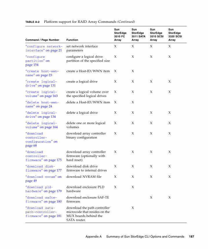
“configure network-interface” on page 21
set network interface parameters
X X X X
“configure partition” on page 154
configure a logical drive partition of the specified size
X X X X
“create host-wwn-name” on page 23
create a Host-ID/WWN item X X
“create logical-drive” on page 131
create a logical drive X X X X
“create logical-volume” on page 163
create a logical volume over the specified logical drives
X X X X
“delete host-wwn-name” on page 24
delete a Host-ID/WWN item X X
“delete logical-drive” on page 134
delete a logical drive X X X X
“delete logical-volume” on page 164
delete one or more logical volumes
X X X X
“download controller-configuration” on page 68
download array controller binary configuration
X X X X
“download controller-firmware” on page 175
download array controller firmware (optionally with hard reset)
X X X X
“download disk-firmware” on page 177
download disk drive firmware to internal drives
X X X X
“download nvram” on page 49
download NVRAM file X X X X
“download pld-hardware” on page 179
download enclosure PLD hardware
X X
“download safte-firmware” on page 180
download enclosure SAF-TE firmware
X X
“download sata-path-controller-firmware” on page 181
download the path controller microcode that resides on the MUX boards behind the SATA router.
X
TABLE A-2 Platform support for RAID Array Commands (Continued)
Command / Page Number Function
Sun StorEdge 3510 FC Array
Sun StorEdge 3511 SATA Array
Sun StorEdge 3310 SCSI Array
Sun StorEdge 3320 SCSI Array
Appendix A Summary of Sun StorEdge CLI Options and Commands 187

“download sata-router-firmware” on page 182
download SR-1216 router firmware to accessible SR-1216 routers behind the RAID controller
X
“download ses-firmware” on page 183
download enclosure SES firmware
X X
“exit” on page 18 exit the Sun StorEdge CLI X X X X
“expand” on page 135 expand a logical drive by the specified size per available physical drive
X X X X
“fail” on page 70 fail a controller in a redundant controller pair
X X X X
“help” on page 19 display help for commands X X X X
“map partition” on page 155
map a logical drive or logical volume partition to a host channel/target/LUN
X X X X
“mute” on page 71 silence the enclosure alarm X X X X
“password” on page 71 specify the array controller password
X X X X
“quit” on page 19 exit the program X X X X
“rebuild” on page 137 rebuild the specified logical drive
X X X X
“reset controller” on page 72
reset the array controller X X X X
“reset nvram” on page 50
restore NVRAM to factory defaults
X X X X
“scan disk” on page 93
scans and makes available a hard drive without having to shut down the array
X X
“select” on page 20 specify a storage device to monitor or configure
X X X X
“set auto-write-through-trigger” on page 32
configure the array to dynamically switch from write-back cache to write-through cache if a specified event occurs
X X X X
TABLE A-2 Platform support for RAID Array Commands (Continued)
Command / Page Number Function
Sun StorEdge 3510 FC Array
Sun StorEdge 3511 SATA Array
Sun StorEdge 3310 SCSI Array
Sun StorEdge 3320 SCSI Array
188 Sun StorEdge 3000 Family CLI 2.4 User’s Guide • March 2007

“set cache-parameters” on page 73
set cache write policy and optimization policy
X X X X
“set controller-date” on page 76
set a controller date and time X X X X
“set controller-name” on page 77
set the controller name X X X X
“set controller-password” on page 77
set the controller password X X X X
“set disk-array” on page 94
set disk array parameters including the background logical drive rebuilding priority and hard drive data verification
X X X X
“set drive-parameters” on page 108
set drive channel parameters X X X X
“set host-parameters” on page 110
set host channel parameters X X X X
“set inter-controller-link” on page 112
enable/disable per-channel inter-controller link
X X
“set led” on page 95 change the drive LED for the specified disk (or slot) from green to amber
X X X X
“set logical-drive” on page 138
set the write policy for a logical drive
X X X X
“set logical-volume” on page 165
set the write policy for the specified logical volume
X X X X
“set protocol” on page 25
enable or disable the specified network protocol and set the Telnet inactivity timeout value.
X X X X
TABLE A-2 Platform support for RAID Array Commands (Continued)
Command / Page Number Function
Sun StorEdge 3510 FC Array
Sun StorEdge 3511 SATA Array
Sun StorEdge 3310 SCSI Array
Sun StorEdge 3320 SCSI Array
Appendix A Summary of Sun StorEdge CLI Options and Commands 189

“To remove an existing password, specify a zero-length string with a pair of double-quote characters. For example:” on page 78
set the RS-232 interface baud rate
X X X X
“set unique-identifier” on page 79
set the subsystem’s six-digit hexadecimal serial number
X X X X
“show access-mode” on page 33
display the Sun StorEdge CLI access mode
X X X X
“show auto-write-through-trigger” on page 34
display the event trigger status for the controller
X X X X
“show battery-status” on page 35
display battery information including battery type, manufacturing data, in-service date, expiration date, and status
X X
“show bypass device” on page 51
display the bypass status of all devices on a specified loop
X X
“show bypass RAID” on page 54
display the hardware bypass status of the RAID controllers on Loop A and Loop B
X X
“show bypass SFP” on page 55
display the bypass status of all SFPs on a specified loop
X X
“show cache-parameters” on page 81
display cache policy X X X X
“show channels” on page 113
display channel configuration
X X X X
“show clone” on page 97
display the progress of disk cloning
X x X X
“show configuration” on page 57
display the RAID enclosure device’s configuration
X X X X
TABLE A-2 Platform support for RAID Array Commands (Continued)
Command / Page Number Function
Sun StorEdge 3510 FC Array
Sun StorEdge 3511 SATA Array
Sun StorEdge 3310 SCSI Array
Sun StorEdge 3320 SCSI Array
190 Sun StorEdge 3000 Family CLI 2.4 User’s Guide • March 2007

“show controller-date” on page 81
display the boot time and date of the RAID controller
X X X X
“show controller-name” on page 82
display controller name X X X X
“show disk-array” on page 97
display the disk array parameters including the logical drive rebuild priority and the hard drive settings for verifying the written data for initializing, rebuilding, and writing normal I/O data
X X X X
“show disks” on page 98
display information for array disks
X X X X
“show disks logical-drive” on page 140
display information for array disks in a logical drive
X X X X
“show drive-parameters” on page 115
display drive parameters X X X X
“show enclosure-status” on page 38
display the status for all chassis components including the fan, power supply, temperature sensor, and drive slots
X X X X
“show events” on page 64
display the controller event log
X X X X
“show frus” on page 45
display FRU-ID information X X X X
“show host-parameters” on page 117
display host I/O parameters X X X X
“show host-wwn-names” on page 27
display all registered HBA WWNs in the controller for host channels
X X
“show inquiry-data” on page 82
display SCSI inquiry data for selected device
X X X X
TABLE A-2 Platform support for RAID Array Commands (Continued)
Command / Page Number Function
Sun StorEdge 3510 FC Array
Sun StorEdge 3511 SATA Array
Sun StorEdge 3310 SCSI Array
Sun StorEdge 3320 SCSI Array
Appendix A Summary of Sun StorEdge CLI Options and Commands 191

“show inter-controller-link” on page 118
display status of inter-controller link on specified channel
X X
“show ip-address” on page 28
display the controller’s IP network address
X X X X
“show led-status” on page 101
display the status of the LED adjacent to the specified disk drive slot in the array enclosure or expansion chassis.
X X X X
“show logical-drive” on page 142
display logical drives X X X X
“show logical-drives add-disk” on page 144
display the status of disks that are being added to a logical drive
X X X X
“show logical-drives expanding” on page 144
display the progress of the logical drive expansion
X X X X
“show logical-drives initializing” on page 145
display the progress of the RAID controller initialization
X X X X
“show logical-drives logical volume” on page 146
display information about for all logical drives in a specified logical volume
X X X X
“show logical-drives parity-check” on page 148
display the parity check progress for a logical drive
X X X X
“show logical-drives rebuilding” on page 149
display the rebuilding progress for all logical drives
X X X X
“show logical-volumes” on page 167
display logical volumes X X X X
“show loop-map” on page 60
display the FC loop positional map for a given channel
X X
“show lun-maps” on page 158
display LUN maps for host channels
X X X X
TABLE A-2 Platform support for RAID Array Commands (Continued)
Command / Page Number Function
Sun StorEdge 3510 FC Array
Sun StorEdge 3511 SATA Array
Sun StorEdge 3310 SCSI Array
Sun StorEdge 3320 SCSI Array
192 Sun StorEdge 3000 Family CLI 2.4 User’s Guide • March 2007

“show media-check” on page 149
display the progress of a media check
X X X X
“show network-parameters” on page 28
display controller network parameters
X X X X
“show partitions” on page 159
display partitions of logical drives
X X X X
“show peripheral-device-status” on page 47
display the status for all environmental sensors for the controller
X X X X
“show port-wwn” on page 29
display host channel FC Port Name WWNs
X X
“show protocol” on page 30
display all possible network protocols supported by the controller or particular information of a specified protocol
X X X X
“show redundancy-mode” on page 84
display redundancy status X X X X
“show redundant-controller” on page 86
display the redundant-controller information
X X X X
“show rs232-configuration” on page 31
display serial port configuration
X X X X
“show safte-device” on page 170
display status of SAF-TE devices
X X
“show sata-mux” on page 171
display the SATA MUX board information for all drives
X
“show sata-router” on page 172
display all accessible SATA routers behind the RAID controller
X
“show ses-devices” on page 173
display status of SES devices, including the PLD revision
X X
“show shutdown-status” on page 86
display the controller shutdown status
X X X X
TABLE A-2 Platform support for RAID Array Commands (Continued)
Command / Page Number Function
Sun StorEdge 3510 FC Array
Sun StorEdge 3511 SATA Array
Sun StorEdge 3310 SCSI Array
Sun StorEdge 3320 SCSI Array
Appendix A Summary of Sun StorEdge CLI Options and Commands 193

“show stripe-size-list” on page 150
display the valid stripe block size list for the specified RAID level
X X X X
“show unique-identifier” on page 87
display subsystem six-digit unique identifier
X X X X
“shutdown controller” on page 88
shut down controller (prepare for power off)
X X X X
“shutdown logical-drive” on page 151
shut down (force offline) a logical drive
X X X X
“unconfigure global-spare” on page 102
unconfigure a global spare drive
X X X X
“unconfigure local-spare” on page 152
unconfigure a local spare drive
X X X X
“unfail” on page 89 restore (deassert) a failed controller
X X X X
“unmap partition” on page 160
unmap a logical drive or logical volume partition from a host channel/target/LUN
X X X X
“upload controller-configuration” on page 89
upload array controller binary configuration
X X X X
“upload nvram” on page 62
upload an NVRAM file X X X X
“version” on page 20 display program version X X X X
TABLE A-2 Platform support for RAID Array Commands (Continued)
Command / Page Number Function
Sun StorEdge 3510 FC Array
Sun StorEdge 3511 SATA Array
Sun StorEdge 3310 SCSI Array
Sun StorEdge 3320 SCSI Array
194 Sun StorEdge 3000 Family CLI 2.4 User’s Guide • March 2007

An “X” in a product column in the following table indicates that the Sun StorEdge CLI command works with that product.
.
TABLE A-3 JBOD Commands
Command / Page Number Function
Sun StorEdge 3510 FC JBOD
Sun StorEdge 3310 SCSI JBOD
Sun StorEdge 3320 SCSI JBOD
Sun StorEdge 3120 SCSI JBOD
“about” on page 18 display program version and copyright info
X X X X
“download pld-hardware” on page 179
download PLD hardware into the SES microprocessor in a FC JBOD device
X
“download safte-firmware” on page 180
download firmware into the microprocessors within a SCSI JBOD
X X X
“download ses-firmware” on page 183
download enclosure SES firmware X
“exit” on page 18 exit the Sun StorEdge CLI X X X X
“help” on page 19 display help for commands X X X X
“quit” on page 19 exit the program X X X X
“select” on page 20 specify a storage device to monitor or configure
X X X X
“set led” on page 95 specify a name for a disk drive slot in the array enclosure or expansion chassis
X X X
“show access-mode” on page 33
display the access mode X X X X
“show configuration” on page 57
display the device’s configuration X X X X
“show enclosure-status” on page 38
display the status for all chassis components including the fan, power supply, temperature sensor, and drive slots
X X X X
“show frus” on page 45 display FRU-ID information X X X X
“show inquiry-data” on page 82
display SCSI inquiry data for selected device
X X X X
“show led-status” on page 101
display the status for the specified disk drive slot in the array enclosure or JBOD
X X X
Appendix A Summary of Sun StorEdge CLI Options and Commands 195

“show safte-device” on page 170
display status of SAF-TE devices X X X
“show ses-devices” on page 173
display status of SES devices including the PLD revision
X
“version” on page 20 display program version X X X X
TABLE A-3 JBOD Commands (Continued)
Command / Page Number Function
Sun StorEdge 3510 FC JBOD
Sun StorEdge 3310 SCSI JBOD
Sun StorEdge 3320 SCSI JBOD
Sun StorEdge 3120 SCSI JBOD
196 Sun StorEdge 3000 Family CLI 2.4 User’s Guide • March 2007

APPENDIX B
Error and Event Messages
This appendix provides a list of error and status messages for the Sun StorEdge CLI. For a list of controller error messages, many of which are passed through to the Sun StorEdge CLI, refer to the Sun StorEdge 3000 Family RAID Firmware User’s Guide.
TABLE B-1 lists the Error and Status messages for the Sun StorEdge CLI.
TABLE B-1 Sun StorEdge CLI Error and Status Messages
Error and Status Messages
Abort checking media failed
Abort checking parity failed
Abort clone failed
Abort creating logical drive failed
Abort expanding logical drive failed
Abort rebuilding logical drive failed
Access device failure
Adding disk failed
Adding disk only applicable on raid0/raid1/raid3/raid5
Another disk or logical drive operation under progress or not applicable operation for current disk or logical drive status
Assigned
Bad connection to the Primary Agent
Bad data returned from controller
Bad event data
Bad firmware data for download
Bad fru id data
197

Bad logical drive channel number
Bad logical drive id in library database
Bad logical drive index in library database
Bad logical host channel number
Bad logical volume id in library database
Bad logical volume index in library database
Bad parameter specified
Bad parameters specified
Bad physical channel number
Bad ses configuration page
Bad socket error
Bad status returned
Battery board does not exist
Battery board FRU ID not programmed
Battery type too old
Can not configure SIDs on single controller environment
Check media failed
Check parity failed
Check parity only applicable on raid1/raid3/raid5
Clear events failure
Clone failed
Clone only applicable on raid0/raid1/raid3/raid5
Close file failure
Close inband/outband device error
Configuration file format error
Controller access error
Controller busy
Controller firmware download ok, but can not engage firmware without redundant controller
Controller firmware download ok, but engage firmware failed
TABLE B-1 Sun StorEdge CLI Error and Status Messages (Continued)
Error and Status Messages
198 Sun StorEdge 3000 Family CLI 2.4 User’s Guide • March 2007

Controller firmware download ok, but engage operation is not allowed
Controller not ready
Controller not shutdown yet as expected
Create host wwn name failed
Data transfer time out
ddb information not programmed
Delete host wwn name failed
Device excluded by redundant path software
Device not supported
Disk drives do not match saved configuration
Drive type unknown
Element not found in ses pages
Element type not found in ses pages
Failed to assign logical drive
Failed to bypass a device
Failed to bypass sfp
Failed to check/set password
Failed to convert logical volume
Failed to create logical drive
Failed to create logical volume
Failed to delete logical volume
Failed to download nvram data
Failed to get battery information
Failed to get cache parameters
Failed to get caching statistics
Failed to get channel data
Failed to get channel statistics
Failed to get controller configuration page
Failed to get controller configuration string page
Failed to get controller module version
TABLE B-1 Sun StorEdge CLI Error and Status Messages (Continued)
Error and Status Messages
Appendix B Error and Event Messages 199

Failed to get controller network interface
Failed to get controller redundant mode
Failed to get controller statistics
Failed to get ctrl param in upload config command
Failed to get drive statistics
Failed to get fru id in upload config command
Failed to get host statistics
Failed to get ld and lv info in upload config command
Failed to get logical drive partition
Failed to get logical drive status
Failed to get loop map
Failed to get lun map in upload config command
Failed to get offset in enclosure page for specified element type
Failed to get peripheral configuration
Failed to get peripheral device status
Failed to get pld register raw data
Failed to get pld rev
Failed to get redundant controller configuration
Failed to get scsi drv info in upload config command
Failed to get ses page
Failed to get sfp bypass information
Failed to get write-policy
Failed to issue a lip
Failed to map logical volume
Failed to map logical volume filter
Failed to map partition to host channel
Failed to mute controller beep
Failed to parse ses configuration page
Failed to partition logical drive/volume
Failed to partition logical volume
TABLE B-1 Sun StorEdge CLI Error and Status Messages (Continued)
Error and Status Messages
200 Sun StorEdge 3000 Family CLI 2.4 User’s Guide • March 2007

Failed to program fru id
Failed to read fru id
Failed to remove logical drive
Failed to remove logical volume
Failed to reset sata router via specified ses target
Failed to reset timeout
Failed to scan fru id
Failed to scan safte
Failed to scan ses target
Failed to send ses page
Failed to set battery all information
Failed to set battery in service date
Failed to set cache parameters
Failed to set channel data
Failed to set controller network interface
Failed to set drive side parameters
Failed to set host side parameters
Failed to set peripheral configuration
Failed to set redundant controller configuration
Failed to set sata serial connector
Failed to set statistics
Failed to set write-policy
Failed to set/reset caching statistics
Failed to set/reset channel statistics
Failed to set/reset controller statistics
Failed to set/reset drive statistics
Failed to set/reset host statistics
Failed to show drive side parameters
Failed to show host side parameters
Failed to show logical volumes
TABLE B-1 Sun StorEdge CLI Error and Status Messages (Continued)
Error and Status Messages
Appendix B Error and Event Messages 201

Failed to show mapping on host channel
Failed to unbypass a device
Failed to unbypass sfp
Failed to unmap partition from host channel
Failed to upload nvram
Filter map exist
Firmware download failure
Firmware download failure on one or more drives, see status report above for failures
Firmware download failure on some targets
Firmware download not performed
Firmware type and unit type do not match
Get events failure
Get host wwn name list failed
Get network protocol failed
Get raid configuration error
Get raid configuration from file error
Get ses wdt status jbod failed
Get slot status failed
Getting network parameters failure
Host wwn entry existing
Host wwn entry not existing
Host wwn name too long
Illegal operation on mixed type of disk drive or unit
Illegal operation while a logical drive exists
Illegal request
In service date not set in the battery
Initializing
Invalid command
Invalid host wwn
Invalid protocol name
TABLE B-1 Sun StorEdge CLI Error and Status Messages (Continued)
Error and Status Messages
202 Sun StorEdge 3000 Family CLI 2.4 User’s Guide • March 2007

Invalid request
Invalid ses enclosure page length
IO chl diagnostic command aborted by user
IO chl diagnostic command bad target parameters
IO chl diagnostic command busy
IO chl diagnostic command completed with errors
IO chl diagnostic command completed with no error
IO chl diagnostic command failed
IO chl diagnostic command in progress
IO chl diagnostic command not ready
IO chl diagnostic command not running
IO chl diagnostic command not valid
IO chl diagnostic command out of resource
IO chl diagnostic command parameter error
IO chl diagnostic command too much ops running
Is member of logical volume
Library database data not valid
Library database update error
Local spare can not be assigned to NRAID or RAID0
Logical drive rebuild failed
Logical drive/volume expand failed
Logical drive/volume expand only applicable on raid0/raid1/raid3/raid5
Logical error of operation on ses
LUN map exist
Maximum error status value
Mixed drive type for a logical drive operation
Mixed drive type in the raid system
Network traffic
No available disk to create logical drive
No controller network interface
TABLE B-1 Sun StorEdge CLI Error and Status Messages (Continued)
Error and Status Messages
Appendix B Error and Event Messages 203

No disk clone found
No firmware data for download
No logical drive
No logical volume
No mux board found
No path found to inquiry sr-1216
No sr-1216 found
No valid data returned
No valid safte target found
No valid ses target found
No valid target found
Not a device mapped on primary controller
Not a drive channel
Not a host channel
Not a primary controller
Not a qualified channel
Not a spare drive
Not a supported SAFTE target
Not a supported SES target
Not a valid target
Not an existing channel
Not an existing target
Not spare drive
Not valid as spare drive
OK
Only offline creating can be aborted
Only offline expanding can be aborted
Open file failure
Open inband/outband device error
Operation not valid on this logical drive
TABLE B-1 Sun StorEdge CLI Error and Status Messages (Continued)
Error and Status Messages
204 Sun StorEdge 3000 Family CLI 2.4 User’s Guide • March 2007

Operation specified not available on the drive type
Out of resource
Partition was not specified
pc-150 firmware download failure
Primary Agent not found
RAID1 requires an even number of disks
Read configuration data error
Rebuild only applicable on raid1/raid3/raid5
Rebuilding
Restore host wwn name list failed
Retrieve
Retrieving
Retrieving controller name failure
Retrieving controller unique id failure
Retrieving ddb information failure
Retrieving pc-150 information failure
Retrieving rs232 configuration failure
Retrieving sr-1216 information failure
Save raid configuration to file error
Scanning fru is done, but at least one fru missing
SCSI device model missing
SCSI drive already exists
SCSI drive not found
SES operation on invalid target
Set controller current time failure
Set logical drive failed
Set logical volume failed
Set network protocol failed
Set ses wdt failed on jbod
Set slot operation failed
TABLE B-1 Sun StorEdge CLI Error and Status Messages (Continued)
Error and Status Messages
Appendix B Error and Event Messages 205
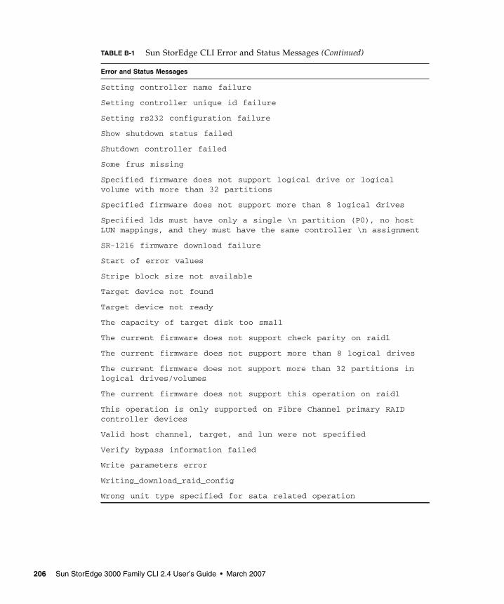
Setting controller name failure
Setting controller unique id failure
Setting rs232 configuration failure
Show shutdown status failed
Shutdown controller failed
Some frus missing
Specified firmware does not support logical drive or logical volume with more than 32 partitions
Specified firmware does not support more than 8 logical drives
Specified lds must have only a single \n partition (P0), no host LUN mappings, and they must have the same controller \n assignment
SR-1216 firmware download failure
Start of error values
Stripe block size not available
Target device not found
Target device not ready
The capacity of target disk too small
The current firmware does not support check parity on raid1
The current firmware does not support more than 8 logical drives
The current firmware does not support more than 32 partitions in logical drives/volumes
The current firmware does not support this operation on raid1
This operation is only supported on Fibre Channel primary RAID controller devices
Valid host channel, target, and lun were not specified
Verify bypass information failed
Write parameters error
Writing_download_raid_config
Wrong unit type specified for sata related operation
TABLE B-1 Sun StorEdge CLI Error and Status Messages (Continued)
Error and Status Messages
206 Sun StorEdge 3000 Family CLI 2.4 User’s Guide • March 2007

APPENDIX C
Show Configuration Command Output
This appendix includes a list of the items included in the output of the show configuration command and the sample XML output of the show configuration XML file command. Regardless of the file format, xml, txt, or onscreen, the output content is the same.
Topics in this appendix include:
■ “Show Configuration Output” on page 208■ “XML DTD for the show configuration --xml Command” on page 215■ “Sample Show Configuration XML Output” on page 240
For details on how to execute the show configuration command, see “show configuration” on page 57.
207

Show Configuration OutputThe show configuration command runs the following commands:
■ show inquiry-data■ show unique-identifier■ show controller-name■ show network-parameters■ show host-parameters■ show drive-parameters■ show redundant-controller■ show redundancy-mode■ show cache-parameters■ show RS232-configuration■ show channels■ show disks■ show logical-drive■ show logical-volumes■ show partitions■ show lun-maps■ show protocol■ show auto-write-through-trigger■ show peripheral-device-status■ show SES■ show port-WWNs■ show inter-controller-link■ show battery-status■ show SAF-TE■ show enclosure-status■ show sata-router■ show sata-mux■ show host-wwns■ show FRUs■ show access-mode■ show controller-date■ show disk array
208 Sun StorEdge 3000 Family CLI 2.4 User’s Guide • March 2007

The XML output produced by show configuration --xml includes the following data.
The Inquiry Data output shows:
■ Vendor■ Product■ Model■ Firmware Revision■ ID of NVRAM Defaults■ Boot Record Version■ MAC Address■ IP Address■ Primary Serial Number■ Secondary Serial Number■ Ethernet Address■ Device Type
The Unique Identifier output shows:
■ Unique ID
The Controller Name output shows:
■ Controller name
The Network Parameters output shows:
■ IP Address■ Netmask■ Gateway■ Mode
The Host Parameters output shows:
■ LUNs per host■ Queue depth■ Fibre connection■ Inband management
The Drive Parameters output shows:
■ SCSI Motor Start-up■ Power-up SCSI Reset■ Disk Access Latency■ SCSI I/O Timeout■ Tag Count Per Drive■ Drive Check Time Period■ Enclosure Polling Period■ Auto-detect Drive Check■ Drive SMART■ Auto Global Spare
Appendix C Show Configuration Command Output 209

The Redundant Controller output shows:
■ Controller configuration■ Cache synchronization■ Host channel failover mode■ Local/Remote redundant mode■ Write-through data synchronization■ Secondary RS232 port status■ Communication channel type
The Redundancy output shows:
■ Role■ Primary Controller Serial Number■ Redundancy Mode■ Redundant Status■ Secondary Controller Serial Number
The Cache Parameters output shows:
■ Write policy mode■ I/O optimization■ Synchronization period
The RS-232 Parameters output shows:
■ Port baud rate
The Channel output shows:
■ Channel ID■ Channel type■ Media type■ PID■ SID■ Current Clock Speed■ Current Width
The Disks output shows:
■ Channel Number■ Target Number■ Status■ Manufacturer■ Model■ Serial Number■ Product Revision■ Capacity■ Size Remaining■ Speed■ LD-ID
210 Sun StorEdge 3000 Family CLI 2.4 User’s Guide • March 2007

The Logical Drive output shows:
■ Logical Drive ID Number (eight-digit hex)■ Logical Drive IDX■ Assignment■ Status■ RAID Level■ Number of Drives■ Physical Drives■ Size■ Total Partitions■ Stripe size■ Write-policy mode
The Logical Volume output shows:
■ Logical Volume ID Number (eight-digit hex)■ Logical Volume IDX■ Controller assignment■ Size■ Write-policy mode■ Logical drive assignment
The Partitions output shows:
■ Logical drive/Logical volume ID■ Partition IDX■ Size
The LUN maps output shows:
■ Channel ID■ Target ID■ LUN■ Partition IDX■ Controller assignment■ Filter map
The Protocol output shows:
■ Protocol type■ Status■ Port number■ Parameters
Appendix C Show Configuration Command Output 211

The Automatic Write-Through Trigger output shows:
■ Controller failure status■ Battery backup status■ UPS AC power loss status■ Power supply status■ Fan failure status■ Temperature exceeded delay status
The Peripheral Device output shows:
■ CPU primary temperature sensor■ Board 1 primary temperature sensor■ Board 2 primary temperature sensor■ +3.3V primary value■ +5V primary value■ +12V primary value■ Battery backup primary battery ■ CPU secondary temperature sensor■ Board 1 secondary temperature sensor■ Board 2 secondary temperature sensor■ +3.3V secondary value■ +5V secondary value■ +12V secondary value■ Battery backup secondary battery
The SES output shows:
■ Channel■ ID■ Chassis Serial Number■ Vendor Product ID■ Revision■ PLD Revision■ WWNN■ WWPN■ Topology
The Port WWN output shows:
■ Channel■ Channel ID■ WWPN
The Inter-Controller Link (ICL) output shows:
■ Channel Number■ Bypass Status
212 Sun StorEdge 3000 Family CLI 2.4 User’s Guide • March 2007

The Battery Status output shows:
■ Name■ Type■ Manufacturing Date■ Placed In-Service Date■ Expiration Date■ Status
The SAF-TE output shows:
■ Channel■ ID■ Chassis Serial Number■ Vendor ■ Product ID■ Revision■ Package Revision
The Enclosure Status output shows:
■ SAF-TE or SES package and revision information■ Fan status■ Power supply status■ Temperature sensor status■ Disk slot status■ EMU status■ SCSI channel type
The SATA router output shows:
■ Enclosure ID■ Enclosure serial number■ Channel■ Slot■ Revision■ Boot revision■ CSB revision■ Hardware revision
The SATA MUX output shows:
■ Channel■ ID■ MUX serial number■ MUX type■ Path controller (PC150) revision■ Path controller (PC150) boot revision
Appendix C Show Configuration Command Output 213

The Host WWN output shows:
■ Host WWN
The FRU information output shows:
■ Name■ Description■ Part Number■ Serial Number■ Revision■ Initial Hardware Dash Level■ FRU Shortname■ Manufacturing Date■ Manufacturing Location■ Manufacturer JEDEC ID■ FRU Location■ Chassis Serial Number■ Status
The Access Mode output shows:
■ Access mode
The Controller Date output shows:
■ Boot time■ Current time■ Time zone
The Disk Array output shows:
■ Verify On Initialization■ Verify On Rebuild■ Verify On Normal■ Rebuild Priority
214 Sun StorEdge 3000 Family CLI 2.4 User’s Guide • March 2007

XML DTD for the show configuration --xml CommandThe show configuration --xml command conforms to the following DTD.
t
<?xml version=”1.0” ?>
<!-- ****************************************************** --><!-- Root element, the RAID BaseView --><!-- ****************************************************** --><!ELEMENT raidbaseview (raidsystem*)>
<!-- ********************************************************* --><!-- raidsystem element : The entire RAID system, which --><!-- consists of: --><!-- name: The RAID System name --><!-- status: the system status --><!-- manufacturer: --><!-- model: product model --><!-- firmware_version: Firmware version --><!-- bootrecord_version: Boot Record version. --><!-- mac_address: network MAC address. --><!-- ip: network IP address. --><!-- netmask: network mask address. --><!-- gateway: network gateway address. --><!-- (optional) --><!-- primary_sn: Primary Serial Number --><!-- secondary_sn: Secondary Serial Number --><!-- (optional) --><!-- controller_name: Controller Name --><!-- unique_id: Unique ID of the RAID System. --><!-- id_of_nvram_defaults: --><!-- total_logical_drives: --><!-- total_partitions: --><!-- total_physical_drives: Total Physical Drivers --><!-- total_ses_devices: --><!-- cache_size: --><!-- cpu: --><!-- fru: Controller FRU info --><!-- (optional) --><!-- channel: RAID System Channel info. --><!-- network: network channel info -->
Appendix C Show Configuration Command Output 215

<!-- (optional) --><!-- com_port: RAID System COM port info --><!-- cache_param: Cache parameter --><!-- array_param: Disk Array parameter --><!-- drive_param: Disk side parameter --><!-- host_param: Host side parameter --><!-- redundant_param: is system in redundant model --><!-- logical_volume Logical Volumes --><!-- (optional) --><!-- logical_drive: Logical Drivers --><!-- (optional) --><!-- ses: the SES device info --><!-- (optional) --><!-- port_wwn: port wwn info (optional) --><!-- inter_controller_link: controller internal link info --><!-- (optional) --><!-- battery_status: Battery status --><!-- (optional) --><!-- config_components Disk and SAFTE device info. --><!-- hostwwns: host wwn info (optional) --><!-- --><!-- boot_time: the controller boot time --><!-- time_zone: time zone --><!-- access_mode: the accesse mode: can be inband or out-of-band --><!-- controller_date: the controller current time --><!-- enclosure: the enclosure information --><!-- network_protocol: one network protocol --><!-- peripheral_device: peripheral device configuration --><!-- peripheral_device_status: peripheral device status --><!-- total_sata_mux: total sata mux number --><!-- total_sata_routers: total sata router number --><!-- ********************************************************* --><!ELEMENT raidsystem (name,status,manufacturer,model,firmware_version,
bootrecord_version,mac_address?,ip?,netmask?,gateway?,
216 Sun StorEdge 3000 Family CLI 2.4 User’s Guide • March 2007

primary_sn,secondary_sn?,controller_name,unique_id?,
id_of_nvram_defaults?,total_logical_drives,total_partitions,
total_physical_drives,total_ses_devices,cache_size,
cpu,fru*,channel+,network*,com_port+,cache_param,
array_param,drive_param,host_param,redundant_param,logical_volume*,logical_drive*,ses*,port_wwns*,inter_controller_link+,battery_status*,config_components,hostwwns*,
boot_time,time_zone,access_mode,controller_date,
enclosure+,network_protocol*,peripheral_device,peripheral_device_status,total_sata_mux,total_sata_routers)>
<!-- ****************************************************** --><!-- total_sata_routers element: --><!-- ****************************************************** --><!ELEMENT total_sata_routers (#PCDATA)>
<!-- ****************************************************** --><!-- total_sata_mux element: --><!-- ****************************************************** --><!ELEMENT total_sata_mux (#PCDATA)>
<!-- ****************************************************** --><!-- controller_date element: --><!-- ****************************************************** --><!ELEMENT controller_date (#PCDATA)>
<!-- ****************************************************** --><!-- access_mode element: --><!-- ****************************************************** --><!ELEMENT access_mode (#PCDATA)>
<!-- ****************************************************** --><!-- time_zone element: --><!-- ****************************************************** --><!ELEMENT time_zone (#PCDATA)>
Appendix C Show Configuration Command Output 217

<!-- ****************************************************** --><!-- boot_time element: --><!-- ****************************************************** --><!ELEMENT boot_time (#PCDATA)>
<!-- ****************************************************** --><!-- name element: --><!-- ****************************************************** --><!ELEMENT name (#PCDATA)>
<!-- ****************************************************** --><!-- status element: --><!-- It may be one of Online, Offline, --><!-- Critical, Degraded --><!-- ****************************************************** --><!ELEMENT status (#PCDATA)>
<!-- ****************************************************** --><!-- manufacturer element: --><!-- ****************************************************** --><!ELEMENT manufacturer (#PCDATA)>
<!-- ****************************************************** --><!-- model element: --><!-- ****************************************************** --><!ELEMENT model (#PCDATA)>
<!-- ****************************************************** --><!-- firmware_version element: --><!-- The RAID system Firmware version --><!-- format is major.minorEnginer --><!-- ****************************************************** --><!ELEMENT firmware_version (#PCDATA)>
<!-- ****************************************************** --><!-- bootrecord_version element: --><!-- The RAID system boot record version --><!-- ****************************************************** --><!ELEMENT bootrecord_version (#PCDATA)>
218 Sun StorEdge 3000 Family CLI 2.4 User’s Guide • March 2007

<!-- ****************************************************** --><!-- primary_sn element: --><!-- The RAID system primary controller serial number --><!-- ****************************************************** --><!ELEMENT primary_sn (#PCDATA)>
<!-- ****************************************************** --><!-- secondary_sn element: --><!-- The RAID system secondary controller serial number --><!-- It is optional, for some systems may have only --><!-- one controller --><!-- ****************************************************** --><!ELEMENT secondary_sn (#PCDATA)>
<!-- ****************************************************** --><!-- controller_name element: --><!-- The RAID system controller name --><!-- ****************************************************** --><!ELEMENT controller_name (#PCDATA)>
<!-- ****************************************************** --><!-- unique_id element: --><!-- The RAID system Unique ID --><!-- ****************************************************** --><!ELEMENT unique_id (#PCDATA)>
<!-- ****************************************************** --><!-- id_of_nvram_defaults element: --><!-- ****************************************************** --><!ELEMENT id_of_nvram_defaults (#PCDATA)>
<!-- ****************************************************** --><!-- total_logical_drives element: --><!-- The RAID system total logical --><!-- drive number --><!-- ****************************************************** --><!ELEMENT total_logical_drives (#PCDATA)>
<!-- ****************************************************** --><!-- total_partitions element: --><!-- The RAID system total partition --><!-- number --><!-- ****************************************************** --><!ELEMENT total_partitions (#PCDATA)>
Appendix C Show Configuration Command Output 219

<!-- ****************************************************** --><!-- total_physical_drives element: --><!-- The RAID system total physical drives --><!-- number --><!-- ****************************************************** --><!ELEMENT total_physical_drives (#PCDATA)>
<!-- ****************************************************** --><!-- total_ses_devices element: --><!-- The RAID system total SAFTE device --><!-- number --><!-- ****************************************************** --><!ELEMENT total_ses_devices (#PCDATA)>
<!-- ****************************************************** --><!-- cache_size element: The cache size, in binary MB --><!-- ****************************************************** --><!ELEMENT cache_size (#PCDATA)>
<!-- ****************************************************** --><!-- cpu element: The CPU type of the RAID system --><!-- ****************************************************** --><!ELEMENT cpu (#PCDATA)>
<!-- ******************************************************** --><!-- fru element: The FRU info of one part of the RAID system --><!-- It includes these elements --><!-- idx: the index --><!-- name: the name of the FRU --><!-- description: --><!-- part_number: the part number --><!-- serial_number: the serial number --><!-- revision: --><!-- manufacturing_date: Manufacture Date --><!-- manufacturing_location: Manufacture Location --><!-- manufacturer_jedec_id: Vendor JEDEC ID --><!-- fru_location: --><!-- chassis_serial_number: sn --><!-- ******************************************************** --><!ELEMENT fru (idx,name,description,part_number,serial_number,
revision,manufacturing_date,manufacturing_location,manufacturer_jedec_id,fru_location,chassis_serial_number, fru_status)>
220 Sun StorEdge 3000 Family CLI 2.4 User’s Guide • March 2007

<!-- ****************************************************** --><!-- fru_status element: --><!-- ****************************************************** --><!ELEMENT fru_status (#PCDATA)>
<!-- ****************************************************** --><!-- idx element: --><!-- ****************************************************** --><!ELEMENT idx (#PCDATA)>
<!-- ****************************************************** --><!-- part_number element: --><!-- ****************************************************** --><!ELEMENT part_number (#PCDATA)>
<!-- ****************************************************** --><!-- revision element: --><!-- ****************************************************** --><!ELEMENT revision (#PCDATA)>
<!-- ****************************************************** --><!-- manufacturer_jedec_id element: --><!-- ****************************************************** --><!ELEMENT manufacturer_jedec_id (#PCDATA)>
<!-- ****************************************************** --><!-- fru_location element: --><!-- ****************************************************** --><!ELEMENT fru_location (#PCDATA)>
<!-- ****************************************************** --><!-- chassis_serial_number element: --><!-- ****************************************************** --><!ELEMENT chassis_serial_number (#PCDATA)>
<!-- ****************************************************** --><!-- manufacturing_date element: --><!-- ****************************************************** --><!ELEMENT manufacturing_date (#PCDATA)>
<!-- ****************************************************** --><!-- manufacturing_location element: --><!-- ****************************************************** --><!ELEMENT manufacturing_location (#PCDATA)>
Appendix C Show Configuration Command Output 221

<!-- ****************************************************** --><!-- description element: --><!-- ****************************************************** --><!ELEMENT description (#PCDATA)>
<!-- ******************************************************** --><!-- channel element: The channel info of the RAID system --><!-- It include these elements --><!-- idx: the index, the physical channel number --><!-- logchl: Logical Channel number --><!-- mode: Channel model --><!-- type: Channel Type --><!-- pid: Channel PID --><!-- sid: Channel SID --><!-- term: Channel Terminal --><!-- defclk: Channel default clock --><!-- curclk: Channel current clock --><!-- defwid: Channel default width --><!-- curwid: Channel current width --><!-- *************************************************** --><!ELEMENT channel (idx,logchl,mode,type,pid,sid,term,
defclk,curclk,defwid,curwid)>
<!-- ****************************************************** --><!-- logchl element: Logical Channel number --><!-- ****************************************************** --><!ELEMENT logchl (#PCDATA)>
<!-- ****************************************************** --><!-- mode element: The Channel work mode can be “Host” --><!-- “Drive”, “RCCOM”, “Other” --><!-- ****************************************************** --><!ELEMENT mode (#PCDATA)>
<!-- ****************************************************** --><!-- type element: Channel type can be “SCSI” “PCI” “FC” --><!-- ****************************************************** --><!ELEMENT type (#PCDATA)>
<!-- ****************************************************** --><!-- pid element: PID of this channel --><!-- ****************************************************** --><!ELEMENT pid (#PCDATA)>
222 Sun StorEdge 3000 Family CLI 2.4 User’s Guide • March 2007

<!-- ****************************************************** --><!-- sid element: SID of this channel --><!-- ****************************************************** --><!ELEMENT sid (#PCDATA)>
<!-- ****************************************************** --><!-- defclk element: Default clock --><!-- ****************************************************** --><!ELEMENT defclk (#PCDATA)>
<!-- ****************************************************** --><!-- defwid element: Default width --><!-- ****************************************************** --><!ELEMENT defwid (#PCDATA)>
<!-- ****************************************************** --><!-- term element: This channel have term or not --><!-- ****************************************************** --><!ELEMENT term (#PCDATA)>
<!-- ****************************************************** --><!-- defclk element: Current clock --><!-- ****************************************************** --><!ELEMENT curclk (#PCDATA)>
<!-- ****************************************************** --><!-- defwid element: Current width --><!-- ****************************************************** --><!ELEMENT curwid (#PCDATA)>
<!-- ******************************************************** --><!-- network element: The channel info of the RAID system --><!-- It includes these elements --><!-- idx: --><!-- mac_address: --><!-- static_address: --><!-- transfer_speed_configurable: --><!-- current_transfer_speed: --><!-- supported_transfer_speed: --><!-- mac_address_configurable: --><!-- *************************************************** -->
Appendix C Show Configuration Command Output 223

<!ELEMENT network (idx,mac_address,static_address,transfer_speed_configurable,
current_transfer_speed,supported_transfer_speed,mac_address_configurable)>
<!-- ****************************************************** --><!-- mac_address element: Mac address --><!-- format is ##:##:##:##:##:## --><!-- ****************************************************** --><!ELEMENT mac_address (#PCDATA)>
<!-- ****************************************************** --><!-- transfer_speed_configurable element: --><!-- ****************************************************** --><!ELEMENT transfer_speed_configurable (#PCDATA)>
<!-- ****************************************************** --><!-- current_transfer_speed element: in MB --><!-- ****************************************************** --><!ELEMENT current_transfer_speed (#PCDATA)>
<!-- ****************************************************** --><!-- supported_transfer_speed element: in MB --><!-- ****************************************************** --><!ELEMENT supported_transfer_speed (#PCDATA)>
<!-- ****************************************************** --><!-- mac_address_configurable element: Enable, Disable --><!-- ****************************************************** --><!ELEMENT mac_address_configurable (#PCDATA)>
<!-- ****************************************************** --><!-- static_address element: --><!-- ****************************************************** --><!ELEMENT static_address (ip, netmask, gateway)>
<!-- ****************************************************** --><!-- ip element: IP address --><!-- ****************************************************** --><!ELEMENT ip (#PCDATA)>
<!-- ****************************************************** --><!-- netmask element: --><!-- ****************************************************** --><!ELEMENT netmask (#PCDATA)>
224 Sun StorEdge 3000 Family CLI 2.4 User’s Guide • March 2007

<!-- ****************************************************** --><!-- gateway element: --><!-- ****************************************************** --><!ELEMENT gateway (#PCDATA)>
<!-- ******************************************************** --><!-- com_port element: The RS-232 port info --><!-- It includes these elements --><!-- idx: the index --><!-- max_bps: --><!-- min_bps: --><!-- default_bps: --><!-- current_bps: --><!-- *************************************************** --><!ELEMENT com_port (idx, max_bps, min_bps, default_bps, current_bps)>
<!-- ****************************************************** --><!-- max_bps element: Max baud rate, in BPS --><!-- ****************************************************** --><!ELEMENT max_bps (#PCDATA)>
<!-- ****************************************************** --><!-- min_bps element: Min baud rate, in BPS --><!-- ****************************************************** --><!ELEMENT min_bps (#PCDATA)>
<!-- ****************************************************** --><!-- default_bps element: Default baud rate, in BPS --><!-- ****************************************************** --><!ELEMENT default_bps (#PCDATA)>
<!-- ****************************************************** --><!-- current_bps element: Current baud rate, in BPS --><!-- ****************************************************** --><!ELEMENT current_bps (#PCDATA)>
Appendix C Show Configuration Command Output 225

<!-- ******************************************************** --><!-- drive_param element: The Drive side configuration --><!-- It includes these elements --><!-- scsi_motor_spin_up: --><!-- power_up_scsi_reset: --><!-- disk_access_latency: --><!-- scsi_io_timeout: --><!-- tag_count_per_drive: --><!-- drive_check_period: --><!-- safte_polling_period: --><!-- auto_detect_drive_check: --><!-- drive_smart_mode --><!-- auto_global_spare --><!-- *************************************************** --><!ELEMENT drive_param (scsi_motor_spin_up,power_up_scsi_reset?,
disk_access_latency,scsi_io_timeout,tag_count_per_drive,drive_check_period,safte_polling_period,auto_detect_drive_check,drive_smart_mode,auto_global_spare)>
<!-- ****************************************************** --><!-- scsi_motor_spin_up element : in sec --><!-- ****************************************************** --><!ELEMENT scsi_motor_spin_up (#PCDATA)>
<!-- ****************************************************** --><!-- power_up_scsi_reset element: --><!-- ****************************************************** --><!ELEMENT power_up_scsi_reset (#PCDATA)>
<!-- ****************************************************** --><!-- disk_access_latency element: --><!-- ****************************************************** --><!ELEMENT disk_access_latency (#PCDATA)>
<!-- ****************************************************** --><!-- tag_count_per_drive element: --><!-- ****************************************************** --><!ELEMENT tag_count_per_drive (#PCDATA)>
<!-- ****************************************************** --><!-- safte_polling_period element: --><!-- ****************************************************** --><!ELEMENT safte_polling_period (#PCDATA)>
226 Sun StorEdge 3000 Family CLI 2.4 User’s Guide • March 2007

<!-- ****************************************************** --><!-- scsi_io_timeout element: --><!-- ****************************************************** --><!ELEMENT scsi_io_timeout (#PCDATA)>
<!-- ****************************************************** --><!-- drive_check_period element: --><!-- ****************************************************** --><!ELEMENT drive_check_period (#PCDATA)>
<!-- ****************************************************** --><!-- auto_detect_drive_check element: --><!-- ****************************************************** --><!ELEMENT auto_detect_drive_check (#PCDATA)>
<!-- ****************************************************** --><!-- drive_smart_mode element: --><!-- ****************************************************** --><!ELEMENT drive_smart_mode (#PCDATA)>
<!-- ****************************************************** --><!-- auto_global_spare element: --><!-- ****************************************************** --><!ELEMENT auto_global_spare (#PCDATA)>
<!-- ******************************************************** --><!-- cache_param element: The RAID system cache info includes --><!-- write_policy : The write policy --><!-- sync_period --><!-- optimization --><!-- ******************************************************** --><!ELEMENT cache_param (write_policy, sync_period?, optimization)>
<!-- ****************************************************** --><!-- optimization element: can be “Enable”, “Disable” --><!-- ****************************************************** --><!ELEMENT optimization (#PCDATA)>
Appendix C Show Configuration Command Output 227

<!-- ******************************************************** --><!-- array_param element: The RAID system array info includes --><!-- verify_on_init --><!-- verify_on_rebuild --><!-- verify_on_normal --><!-- rebuild_priority --><!-- ******************************************************** --><!ELEMENT array_param (verify_on_init, verify_on_rebuild, verify_on_normal, rebuild_priority)>
<!-- ****************************************************** --><!-- verify_on_init element: can be “Enable” “Disable” --><!-- ****************************************************** --><!ELEMENT verify_on_init (#PCDATA)>
<!-- ****************************************************** --><!-- verify_on_rebuild element: can be “Enable” “Disable” --><!-- ****************************************************** --><!ELEMENT verify_on_rebuild (#PCDATA)>
<!-- ****************************************************** --><!-- verify_on_normal element: can be “Enable” “Disable” --><!-- ****************************************************** --><!ELEMENT verify_on_normal (#PCDATA)>
<!-- ****************************************************** --><!-- rebuild_priority element: can be “High” “Improved” --><!-- “Normal” “Low” --><!-- ****************************************************** --><!ELEMENT rebuild_priority (#PCDATA)>
<!-- ****************************************************** --><!-- host_param element: The RAID system host side info, include --><!-- queue_io_count --><!-- luns_per_host --><!-- fibre_connection_mode --><!-- inband_access --><!-- ****************************************************** --><!ELEMENT host_param (queue_io_count,luns_per_host,
fibre_connection_mode,inband_access?)>
228 Sun StorEdge 3000 Family CLI 2.4 User’s Guide • March 2007

<!-- ****************************************************** --><!-- queue_io_count element: --><!-- ****************************************************** --><!ELEMENT queue_io_count (#PCDATA)>
<!-- ****************************************************** --><!-- luns_per_host element: --><!-- ****************************************************** --><!ELEMENT luns_per_host (#PCDATA)>
<!-- ****************************************************** --><!-- fibre_connection_mode element: --><!-- ****************************************************** --><!ELEMENT fibre_connection_mode (#PCDATA)>
<!-- ******************************************************** --><!-- redundant_param element: The RAID system redundant config , include --><!-- Primary_sn --><!-- Redundancy_mode --><!-- redundant_status --><!-- secondary_sn --><!-- ******************************************************** --><!ELEMENT redundant_param (role,Primary_sn,Redundancy_mode,
redundant_status,secondary_sn)>
<!-- ****************************************************** --><!-- role element: --><!-- ****************************************************** --><!ELEMENT role (#PCDATA)>
<!-- ****************************************************** --><!-- Primary_sn element: --><!-- ****************************************************** --><!ELEMENT Primary_sn (#PCDATA)>
<!-- ****************************************************** --><!-- Redundancy_mode element: --><!-- ****************************************************** --><!ELEMENT Redundancy_mode (#PCDATA)>
<!-- ****************************************************** --><!-- redundant_status element: --><!-- ****************************************************** --><!ELEMENT redundant_status (#PCDATA)>
Appendix C Show Configuration Command Output 229

<!-- ******************************************************** --><!-- logical_drive element: The Logical Drive info includes --><!-- ld_id --><!-- ld_idx --><!-- assignment --><!-- status --><!-- raid_level --><!-- number_of_drives --><!-- physical_drive --><!-- size --><!-- total_partitions --><!-- partition --><!-- ******************************************************** --><!ELEMENT logical_drive (ld_id,ld_idx,assignment,status,
raid_level,number_of_drives,physical_drive,size,total_partitions?,partition*,write_policy?,block_size?)>
<!-- ****************************************************** --><!-- write_policy element: --><!-- ****************************************************** --><!ELEMENT write_policy (#PCDATA)>
<!-- ****************************************************** --><!-- block_size element: --><!-- ****************************************************** --><!ELEMENT block_size (#PCDATA)>
<!-- ****************************************************** --><!-- ld_id element: --><!-- ****************************************************** --><!ELEMENT ld_id (#PCDATA)>
<!-- ****************************************************** --><!-- ld_idx element: --><!-- ****************************************************** --><!ELEMENT ld_idx (#PCDATA)>
<!-- ****************************************************** --><!-- assignment element: --><!-- ****************************************************** --><!ELEMENT assignment (#PCDATA)>
230 Sun StorEdge 3000 Family CLI 2.4 User’s Guide • March 2007

<!-- ****************************************************** --><!-- raid_level element: can be RAID0, RAID1, RAID3 .... --><!-- ****************************************************** --><!ELEMENT raid_level (#PCDATA)>
<!-- ****************************************************** --><!-- number_of_drives element: --><!-- ****************************************************** --><!ELEMENT number_of_drives (#PCDATA)>
<!-- ****************************************************** --><!-- physical_drive element: --><!-- ****************************************************** --><!ELEMENT physical_drive (#PCDATA)>
<!-- ****************************************************** --><!-- size element: in MB --><!-- ****************************************************** --><!ELEMENT size (#PCDATA)>
<!-- ******************************************************** --><!-- ses element: The SES device info includes --><!-- idx: index number --><!-- ch: channel number --><!-- id: SCSI ID --><!-- chassis --><!-- vender_product_id --><!-- rev --><!-- pld --><!-- wwnn --><!-- wwpn --><!-- topology --><!-- ******************************************************** --><!ELEMENT ses (idx,ch,id,chassis,vender_product_id,
rev,pld,wwnn,wwpn,topology)>
<!-- ****************************************************** --><!-- id element: --><!-- ****************************************************** --><!ELEMENT id (#PCDATA)>
<!-- ****************************************************** --><!-- chassis element: --><!-- ****************************************************** --><!ELEMENT chassis (#PCDATA)>
Appendix C Show Configuration Command Output 231

<!-- ****************************************************** --><!-- vender_product_id element: --><!-- ****************************************************** --><!ELEMENT vender_product_id (#PCDATA)>
<!-- ****************************************************** --><!-- rev element: --><!-- ****************************************************** --><!ELEMENT rev (#PCDATA)>
<!-- ****************************************************** --><!-- pld element: --><!-- ****************************************************** --><!ELEMENT pld (#PCDATA)>
<!-- ****************************************************** --><!-- wwnn element: --><!-- ****************************************************** --><!ELEMENT wwnn (#PCDATA)>
<!-- ****************************************************** --><!-- wwpn element: --><!-- ****************************************************** --><!ELEMENT wwpn (#PCDATA)>
<!-- ****************************************************** --><!-- topology element: --><!-- ****************************************************** --><!ELEMENT topology (#PCDATA)>
<!-- ******************************************************** --><!-- port_wwns element: include --><!-- port_wwn --><!-- ******************************************************** --><!ELEMENT port_wwns (port_wwn*)>
<!-- ******************************************************** --><!-- port_wwn element: include --><!-- idx --><!-- ch --><!-- id --><!-- wwnn --><!-- ******************************************************** --><!ELEMENT port_wwn (idx,ch,id,wwnn)>
232 Sun StorEdge 3000 Family CLI 2.4 User’s Guide • March 2007

<!-- ******************************************************** --><!-- hostwwns element: include --><!-- hostwwns --><!-- ******************************************************** --><!ELEMENT hostwwns (hostwwns*)>
<!-- ******************************************************** --><!-- hostwwn element: include --><!-- wwn --><!-- name --><!-- ******************************************************** --><!ELEMENT hostwwn (wwn,name)>
<!-- ****************************************************** --><!-- wwn element: --><!-- ****************************************************** --><!ELEMENT wwn (#PCDATA)>
<!-- ******************************************************** --><!-- inter_controller_link element: include --><!-- idx --><!-- slot --><!-- ch --><!-- ch_mode --><!-- bypass_status --><!-- ******************************************************** --><!ELEMENT inter_controller_link (idx,slot,ch,ch_mode,bypass_status)>
<!-- ****************************************************** --><!-- slot element: --><!-- ****************************************************** --><!ELEMENT slot (#PCDATA)>
<!-- ****************************************************** --><!-- ch_mode element: --><!-- ****************************************************** --><!ELEMENT ch_mode (#PCDATA)>
<!-- ****************************************************** --><!-- bypass_status element: --><!-- ****************************************************** --><!ELEMENT bypass_status (#PCDATA)>
Appendix C Show Configuration Command Output 233

<!-- ******************************************************** --><!-- battery_status element: battery status info includes --><!-- name --><!-- type --><!-- manufacturing_date --><!-- placed_in_service --><!-- ******************************************************** --><!ELEMENT battery_status (name,type,manufacturing_date,placed_in_service)>
<!-- ****************************************************** --><!-- placed_in_service element: --><!-- ****************************************************** --><!ELEMENT placed_in_service (#PCDATA)>
<!-- ******************************************************** --><!-- partition element: The partition info includes --><!-- idx --><!-- effective_size --><!-- offset --><!-- mapping --><!-- ******************************************************** --><!ELEMENT partition (idx, effective_size, offset, mapping?, filter_mapping?)> <!-- ****************************************************** --><!-- effective_size element: in MB --><!-- ****************************************************** --><!ELEMENT effective_size (#PCDATA)>
<!-- ****************************************************** --><!-- offset element: in MB --><!-- ****************************************************** --><!ELEMENT offset (#PCDATA)>
<!-- ****************************************************** --><!-- mapping element: --><!-- ****************************************************** --><!ELEMENT mapping (#PCDATA)>
<!-- ****************************************************** --><!-- filter_mapping element: --><!-- ****************************************************** --><!ELEMENT filter_mapping (#PCDATA)>
234 Sun StorEdge 3000 Family CLI 2.4 User’s Guide • March 2007

<!-- ******************************************************** --><!-- logical_volume element: The Logical Volume info, include --><!-- lv_id --><!-- lv_idx --><!-- assignment --><!-- status --><!-- size --><!-- logical_drive --><!-- total_partitions --><!-- partition --><!-- ******************************************************** --><!ELEMENT logical_volume (lv_id,lv_idx,assignment,status,
size,logical_drive,total_partitions,write_policy?,partition+)>
<!-- ****************************************************** --><!-- lv_id element: --><!-- ****************************************************** --><!ELEMENT lv_id (#PCDATA)>
<!-- ****************************************************** --><!-- number_of_logical_drive element: LV include LD number --><!-- ****************************************************** --><!ELEMENT number_of_logical_drive (#PCDATA)>
<!-- ****************************************************** --><!-- lv_idx element: --><!-- ****************************************************** --><!ELEMENT lv_idx (#PCDATA)>
<!-- ******************************************************** --><!-- config_components element: --><!-- ******************************************************** --><!ELEMENT config_components (disk*)>
<!-- ******************************************************** --><!-- Disk element: --><!-- ******************************************************** --><!ELEMENT disk (ch,target,status,manufacturer,model,
serial_number, product_revision,capacity,remaining_size,rpm,ld_id,ld_idx,wwnn?,Speed)>
Appendix C Show Configuration Command Output 235

<!-- ****************************************************** --><!-- wwnn element: --><!-- ****************************************************** --><!ELEMENT wwnn (#PCDATA)><!-- ****************************************************** --><!-- ch element: --><!-- ****************************************************** --><!ELEMENT ch (#PCDATA)>
<!-- ****************************************************** --><!-- target element: --><!-- ****************************************************** --><!ELEMENT target (#PCDATA)>
<!-- ****************************************************** --><!-- serial_number element: --><!-- ****************************************************** --><!ELEMENT serial_number (#PCDATA)>
<!-- ****************************************************** --><!-- product_revision element: --><!-- ****************************************************** --><!ELEMENT product_revision (#PCDATA)>
<!-- ****************************************************** --><!-- capacity element: --><!-- ****************************************************** --><!ELEMENT capacity (#PCDATA)>
<!-- ****************************************************** --><!-- remaining_size element: --><!-- ****************************************************** --><!ELEMENT remaining_size (#PCDATA)>
<!-- ****************************************************** --><!-- Speed element: --><!-- ****************************************************** --><!ELEMENT Speed (#PCDATA)>
<!-- ******************************************************** --><!-- CDROM element: --><!-- ******************************************************** --><!ELEMENT cdrom (ch, target, manufacturer, model)>
236 Sun StorEdge 3000 Family CLI 2.4 User’s Guide • March 2007

<!-- ******************************************************** --><!-- Tape element: --><!-- ******************************************************** --><!ELEMENT tape (ch, target, manufacturer, model)>
<!-- ******************************************************** --><!-- EMU element: --><!-- ******************************************************** --><!ELEMENT emu (ch, target, status, manufacturer, model, firmware_version, safte_status, fru_number, fru*)>
<!-- ******************************************************** --><!-- fru_number element: --><!-- ******************************************************** --><!ELEMENT fru_number (#PCDATA)>
<!-- ******************************************************** --><!-- safte_status element: --><!-- ******************************************************** --><!ELEMENT safte_status (idx, power_status_summary, power_supply_status?, fan_status_summary, fan_status?, temperature_status)>
<!-- ******************************************************** --><!-- power_status_summary element: --><!-- ******************************************************** --><!ELEMENT power_status_summary (#PCDATA)>
<!-- ******************************************************** --><!-- fan_status_summary element: --><!-- ******************************************************** --><!ELEMENT fan_status_summary (#PCDATA)>
<!-- ******************************************************** --><!-- temperature_status element: --><!-- ******************************************************** --><!ELEMENT temperature_status (#PCDATA)>
<!-- ******************************************************** --><!-- power_supply_status element: --><!-- ******************************************************** --><!ELEMENT power_supply_status (idx, status)>
Appendix C Show Configuration Command Output 237

<!-- ******************************************************** --><!-- fan_status element: --><!-- ******************************************************** --><!ELEMENT fan_status (idx, status)>
<!-- ******************************************************** --><!-- enclosure element: include below elements. --><!-- mgmt_device --><!-- component --><!-- ******************************************************** --><!ELEMENT enclosure (mgmt_device+,component+)>
<!-- ******************************************************** --><!-- mgmt_device element: --><!-- ******************************************************** --><!ELEMENT mgmt_device (idx, name)>
<!-- ******************************************************** --><!-- component element: --><!-- ******************************************************** --><!ELEMENT component (addr|led|temp)*>
<!ATTLIST componentfru-pn CDATA #REQUIREDfru-sn CDATA #REQUIREDstatus CDATA #REQUIREDtype CDATA #REQUIREDunit CDATA #REQUIRED
>
<!-- ******************************************************** --><!-- config_components element: --><!-- ******************************************************** --><!ELEMENT config_components (disk*)>
<!-- ******************************************************** --><!-- device element: --><!-- ******************************************************** --><!ELEMENT device (name,value,status)>
<!-- ******************************************************** --><!-- value element: --><!-- ******************************************************** --><!ELEMENT value (#PCDATA)>
238 Sun StorEdge 3000 Family CLI 2.4 User’s Guide • March 2007

<!-- ******************************************************** --><!-- event_trigger_operation_enables element: --><!-- ******************************************************** --><!ELEMENT event_trigger_operation_enables (controller_failure, battery_backup_unit_failure, UPS_AC_power_loss,power_supply_failure, fan_failure)>
<!-- ******************************************************** --><!-- network_protocol element: --><!-- ******************************************************** --><!ELEMENT network_protocol (identifier,status,port_number)>
<!-- ******************************************************** --><!-- peripheral_device element: --><!-- ******************************************************** --><!ELEMENT peripheral_device ( event_trigger_operation_enables, temperature-exceeded-delay)>
<!-- ******************************************************** --><!-- peripheral_device_status element: --><!-- ******************************************************** --><!ELEMENT peripheral_device_status (device+)>
<!-- ******************************************************** --><!-- sync_period element: --><!-- ******************************************************** --><!ELEMENT sync_period (#PCDATA)> <!-- ******************************************************** --><!-- controller_failure element: disabled or enabled --><!-- ******************************************************** --><!ELEMENT controller_failure (#PCDATA)>
<!-- ******************************************************** --><!-- battery_backup_unit_failure element: --><!-- ******************************************************** --><!ELEMENT battery_backup_unit_failure (#PCDATA)>
<!-- ******************************************************** --><!-- UPS_AC_power_loss element: --><!-- ******************************************************** --><!ELEMENT UPS_AC_power_loss (#PCDATA)>
Appendix C Show Configuration Command Output 239

Sample Show Configuration XML
OutputThe following pages show a sample of the show configuration command output in XML format for the Sun StorEdge 3511 SATA array. The following output is specific to that configuration. Each configuration varies, based on how the array is set up. Regardless of the file format, xml or txt or onscreen, the output content is the same.
<!-- ******************************************************** --><!-- power_supply_failure element: --><!-- ******************************************************** --><!ELEMENT power_supply_failure (#PCDATA)> <!-- ******************************************************** --><!-- fan_failure element: --><!-- ******************************************************** --><!ELEMENT fan_failure (#PCDATA)>
<!-- ******************************************************** --><!-- identifier element: --><!-- ******************************************************** --><!ELEMENT identifier (#PCDATA)>
<!-- ******************************************************** --><!-- port_number element: --><!-- ******************************************************** --><!ELEMENT port_number (#PCDATA)> <!-- ******************************************************** --><!-- temperature-exceeded-delay element: --><!-- ******************************************************** --><!ELEMENT temperature-exceeded-delay (#PCDATA)>
240 Sun StorEdge 3000 Family CLI 2.4 User’s Guide • March 2007

<raidbaseview><raidsystem><name>StorEdge 3511 A-A Array SN#0927C0</name><status>Online</status><manufacturer>SUN</manufacturer><model>StorEdge 3511</model><firmware_version>421C</firmware_version><bootrecord_version>1.31H</bootrecord_version><mac_address>00:c0:ff:09:27:c0</mac_address><ip>10.1.74.212</ip><netmask>255.255.255.0</netmask><gateway>10.1.74.1</gateway><primary_sn>8027229</primary_sn><secondary_sn>8027194</secondary_sn><controller_name></controller_name><unique_id>0x927C0</unique_id><id_of_nvram_defaults>421C 3511 S474T</id_of_nvram_defaults><total_logical_drives>3</total_logical_drives><total_partitions>3</total_partitions><total_physical_drives>23</total_physical_drives><total_ses_devices>2</total_ses_devices><cache_size>1024MB ECC SDRAM</cache_size><cpu>PPC750</cpu><fru><idx>0</idx><name>FC_CHASSIS_BKPLN</name><description>SATA,Chassis+Backplane, 2U</description><part_number>370-6775</part_number><serial_number>07ECE4</serial_number><revision>01</revision><Initial_Hardware_Dash_Level>01</Initial_Hardware_Dash_Level><FRU_Shortname>SATA Backplane</FRU_Shortname><manufacturing_date>Thu Mar 18 03:27:55 2004</manufacturing_date><manufacturing_location>Milpitas California, USA</manufacturing_location><manufacturer_jedec_id>0x0301</manufacturer_jedec_id><fru_location>FC MIDPLANE SLOT</fru_location><chassis_serial_number>07ECE4</chassis_serial_number><fru_status>OK</fru_status></fru>
Appendix C Show Configuration Command Output 241

<fru><idx>1</idx><name>FC_JBOD_IOM</name><description>I/O JBOD, SATA, 2U</description><part_number>370-6774</part_number><serial_number>GG0042</serial_number><revision>01</revision><Initial_Hardware_Dash_Level>01</Initial_Hardware_Dash_Level><FRU_Shortname>SATA I/O JBOD</FRU_Shortname><manufacturing_date>Sat Jun 26 18:32:29 2004</manufacturing_date><manufacturing_location>Milpitas,CA,USA</manufacturing_location><manufacturer_jedec_id>0x0301</manufacturer_jedec_id><fru_location>UPPER FC JBOD IOM SLOT</fru_location><chassis_serial_number>07ECE4</chassis_serial_number><fru_status>OK</fru_status></fru><fru><idx>2</idx><name>AC_POWER_SUPPLY</name><description>SE3310/SE3510 AC PWR SUPPLY w/FAN</description><part_number>370-5398</part_number><serial_number>114536</serial_number><revision>02</revision><Initial_Hardware_Dash_Level>02</Initial_Hardware_Dash_Level><FRU_Shortname>370-5398-02</FRU_Shortname><manufacturing_date>Sat Nov 29 15:00:56 2003</manufacturing_date><manufacturing_location>Irvine California, USA</manufacturing_location><manufacturer_jedec_id>0x048F</manufacturer_jedec_id><fru_location>RIGHT AC PSU SLOT #1 (RIGHT)</fru_location><chassis_serial_number>07ECE4</chassis_serial_number><fru_status>OK</fru_status></fru><fru><idx>3</idx><name>AC_POWER_SUPPLY</name><description>SE3310/SE3510 AC PWR SUPPLY w/FAN</description><part_number>370-5398</part_number><serial_number>115884</serial_number><revision>02</revision><Initial_Hardware_Dash_Level>02</Initial_Hardware_Dash_Level><FRU_Shortname>370-5398-02</FRU_Shortname>
242 Sun StorEdge 3000 Family CLI 2.4 User’s Guide • March 2007
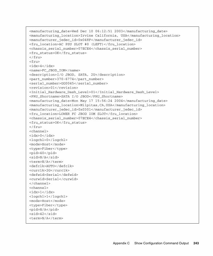
<manufacturing_date>Wed Dec 10 06:12:51 2003</manufacturing_date><manufacturing_location>Irvine California, USA</manufacturing_location><manufacturer_jedec_id>0x048F</manufacturer_jedec_id><fru_location>AC PSU SLOT #0 (LEFT)</fru_location><chassis_serial_number>07ECE4</chassis_serial_number><fru_status>OK</fru_status></fru><fru><idx>4</idx><name>FC_JBOD_IOM</name><description>I/O JBOD, SATA, 2U</description><part_number>370-6774</part_number><serial_number>GG0045</serial_number><revision>01</revision><Initial_Hardware_Dash_Level>01</Initial_Hardware_Dash_Level><FRU_Shortname>SATA I/O JBOD</FRU_Shortname><manufacturing_date>Mon May 17 15:56:24 2004</manufacturing_date><manufacturing_location>Milpitas,CA,USA</manufacturing_location><manufacturer_jedec_id>0x0301</manufacturer_jedec_id><fru_location>LOWER FC JBOD IOM SLOT</fru_location><chassis_serial_number>07ECE4</chassis_serial_number><fru_status>OK</fru_status></fru><channel><idx>0</idx><logchl>0</logchl><mode>Host</mode><type>Fiber</type><pid>40</pid><sid>N/A</sid><term>N/A</term><defclk>AUTO</defclk><curclk>2G</curclk><defwid>Serial</defwid><curwid>Serial</curwid></channel><channel><idx>1</idx><logchl>1</logchl><mode>Host</mode><type>Fiber</type><pid>N/A</pid><sid>42</sid><term>N/A</term>
Appendix C Show Configuration Command Output 243

<defclk>AUTO</defclk><curclk>N/A</curclk><defwid>Serial</defwid><curwid>N/A</curwid></channel><channel><idx>2</idx><logchl>0</logchl><mode>DRV+RCC</mode><type>Fiber</type><pid>14</pid><sid>15</sid><term>N/A</term><defclk>AUTO</defclk><curclk>2G</curclk><defwid>Serial</defwid><curwid>Serial</curwid></channel><channel><idx>3</idx><logchl>1</logchl><mode>DRV+RCC</mode><type>Fiber</type><pid>14</pid><sid>15</sid><term>N/A</term><defclk>AUTO</defclk><curclk>2G</curclk><defwid>Serial</defwid><curwid>Serial</curwid></channel><channel><idx>4</idx><logchl>2</logchl><mode>Host</mode><type>Fiber</type><pid>44</pid><sid>N/A</sid><term>N/A</term><defclk>AUTO</defclk><curclk>2G</curclk><defwid>Serial</defwid><curwid>Serial</curwid></channel>
244 Sun StorEdge 3000 Family CLI 2.4 User’s Guide • March 2007
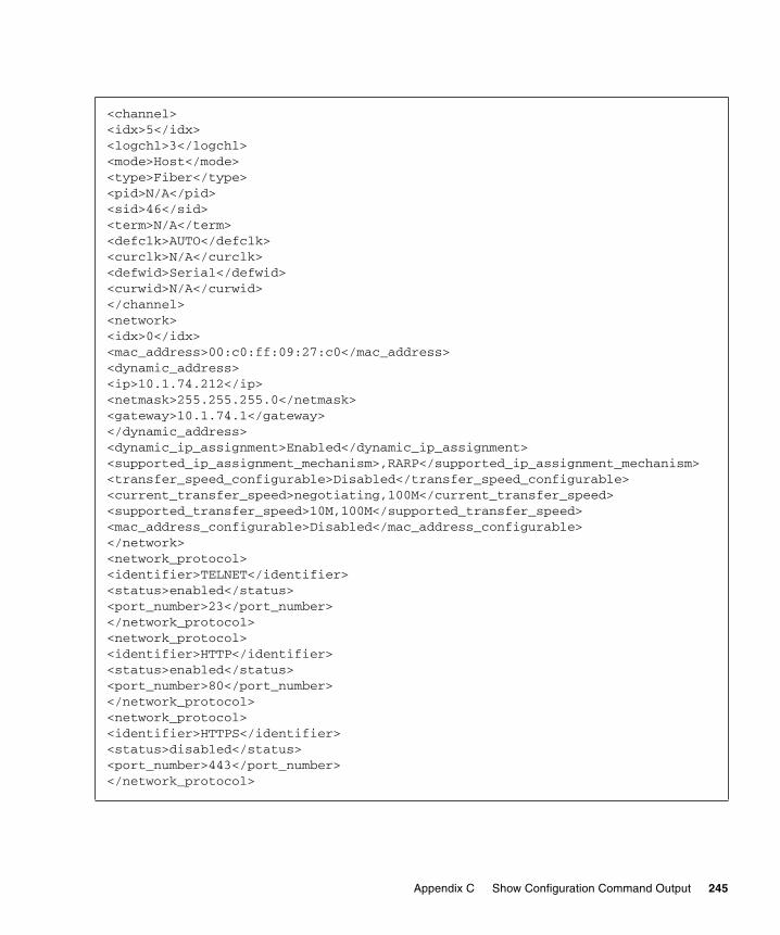
<channel><idx>5</idx><logchl>3</logchl><mode>Host</mode><type>Fiber</type><pid>N/A</pid><sid>46</sid><term>N/A</term><defclk>AUTO</defclk><curclk>N/A</curclk><defwid>Serial</defwid><curwid>N/A</curwid></channel><network><idx>0</idx><mac_address>00:c0:ff:09:27:c0</mac_address><dynamic_address><ip>10.1.74.212</ip><netmask>255.255.255.0</netmask><gateway>10.1.74.1</gateway></dynamic_address><dynamic_ip_assignment>Enabled</dynamic_ip_assignment><supported_ip_assignment_mechanism>,RARP</supported_ip_assignment_mechanism><transfer_speed_configurable>Disabled</transfer_speed_configurable><current_transfer_speed>negotiating,100M</current_transfer_speed><supported_transfer_speed>10M,100M</supported_transfer_speed><mac_address_configurable>Disabled</mac_address_configurable></network><network_protocol><identifier>TELNET</identifier><status>enabled</status><port_number>23</port_number></network_protocol><network_protocol><identifier>HTTP</identifier><status>enabled</status><port_number>80</port_number></network_protocol><network_protocol><identifier>HTTPS</identifier><status>disabled</status><port_number>443</port_number></network_protocol>
Appendix C Show Configuration Command Output 245
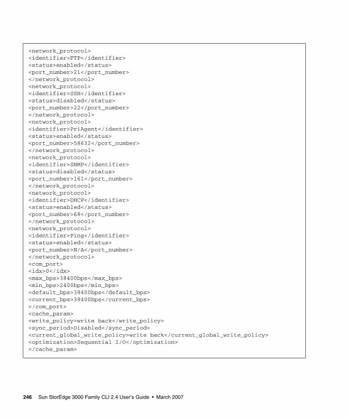
<network_protocol><identifier>FTP</identifier><status>enabled</status><port_number>21</port_number></network_protocol><network_protocol><identifier>SSH</identifier><status>disabled</status><port_number>22</port_number></network_protocol><network_protocol><identifier>PriAgent</identifier><status>enabled</status><port_number>58632</port_number></network_protocol><network_protocol><identifier>SNMP</identifier><status>disabled</status><port_number>161</port_number></network_protocol><network_protocol><identifier>DHCP</identifier><status>enabled</status><port_number>68</port_number></network_protocol><network_protocol><identifier>Ping</identifier><status>enabled</status><port_number>N/A</port_number></network_protocol><com_port><idx>0</idx><max_bps>38400bps</max_bps><min_bps>2400bps</min_bps><default_bps>38400bps</default_bps><current_bps>38400bps</current_bps></com_port><cache_param><write_policy>write back</write_policy><sync_period>Disabled</sync_period><current_global_write_policy>write back</current_global_write_policy><optimization>Sequential I/O</optimization></cache_param>
246 Sun StorEdge 3000 Family CLI 2.4 User’s Guide • March 2007

<peripheral_device><event_trigger_operation_enables><controller_failure>enabled</controller_failure><battery_backup_unit_failure>enabled</battery_backup_unit_failure><UPS_AC_power_loss>disabled</UPS_AC_power_loss><power_supply_failure>enabled</power_supply_failure><fan_failure>enabled</fan_failure></event_trigger_operation_enables><temperature-exceeded-delay>30min</temperature-exceeded-delay></peripheral_device><peripheral_device_status><device><name>CPU Temp Sensor(primary)</name><value>35.50C</value><status>within safety range</status></device><device><name>Board1 Temp Sensor(primary)</name><value>41.50C</value><status>within safety range</status></device><device><name>Board2 Temp Sensor(primary)</name><value>52.00C</value><status>within safety range</status></device><device><name>+3.3V Value(primary)</name><value>3.432V</value><status>within safety range</status></device><device><name>+5V Value(primary)</name><value>5.099V</value><status>within safety range</status></device><device><name>+12V Value(primary)</name><value>12.320V</value><status>within safety range</status></device>
Appendix C Show Configuration Command Output 247

<device><name>Battery-Backup Battery(primary)</name><value>06</value><status>N/A</status></device><device><name>CPU Temp Sensor(secondary)</name><value>40.00C</value><status>within safety range</status></device><device><name>Board1 Temp Sensor(secondary)</name><value>48.00C</value><status>within safety range</status></device><device><name>Board2 Temp Sensor(secondary)</name><value>55.00C</value><status>within safety range</status></device><device><name>+3.3V Value(secondary)</name><value>3.352V</value><status>within safety range</status></device><device><name>+5V Value(secondary)</name><value>5.072V</value><status>within safety range</status></device><device><name>+12V Value(secondary)</name><value>12.199V</value><status>within safety range</status></device><device><name>Battery-Backup Battery(secondary)</name><value>00</value><status>N/A</status></device></peripheral_device_status>
248 Sun StorEdge 3000 Family CLI 2.4 User’s Guide • March 2007

<array_param><verify_on_init>Disabled</verify_on_init><verify_on_rebuild>Disabled</verify_on_rebuild><verify_on_normal>Disabled</verify_on_normal><rebuild_priority>Low</rebuild_priority></array_param><drive_param><scsi_motor_spin_up>Disabled</scsi_motor_spin_up><disk_access_latency>15S</disk_access_latency><scsi_io_timeout>30s</scsi_io_timeout><tag_count_per_drive>32</tag_count_per_drive><drive_check_period>30s</drive_check_period><safte_polling_period>30s</safte_polling_period><auto_detect_drive_check>Disabled</auto_detect_drive_check><drive_smart_mode>disabled</drive_smart_mode><auto_global_spare>Disabled</auto_global_spare></drive_param><host_param><queue_io_count>1024</queue_io_count><luns_per_host>32</luns_per_host><fibre_connection_mode>loop</fibre_connection_mode><inband_access>enabled</inband_access></host_param><redundant_param><role>Redundant Primary</role><Primary_sn>8027229</Primary_sn><Redundancy_mode>Active-Active</Redundancy_mode><Redundancy_status>Enabled</Redundancy_status><redundant_config>Primary controller</redundant_config><secondary_sn>8027194</secondary_sn></redundant_param><logical_drive><ld_id>7C01DB6C</ld_id><ld_idx>0</ld_idx><assignment>Primary</assignment><status>Good</status><raid_level>RAID 5</raid_level><write_policy>default</write_policy><block_size>128 KB</block_size><number_of_drives>3</number_of_drives><physical_drive>3.13 3.14 3.16</physical_drive><size>48.83GB</size><total_partitions>1</total_partitions>
Appendix C Show Configuration Command Output 249

<partition><idx>0</idx><effective_size>48.83GB</effective_size><offset>0MB</offset><mapping>N/A</mapping></partition></logical_drive><logical_drive><ld_id>64A046F7</ld_id><ld_idx>1</ld_idx><assignment>Primary</assignment><status>Good</status><raid_level>RAID 5</raid_level><write_policy>default</write_policy><block_size>128 KB</block_size><number_of_drives>3</number_of_drives><physical_drive>3.17 3.18 3.19</physical_drive><size>48.83GB</size><total_partitions>1</total_partitions><partition><idx>0</idx><effective_size>48.83GB</effective_size><offset>0MB</offset><mapping>N/A</mapping></partition></logical_drive><logical_drive><ld_id>460FDB54</ld_id><ld_idx>2</ld_idx><assignment>Primary</assignment><status>Good</status><raid_level>RAID 5</raid_level><write_policy>default</write_policy><block_size>128 KB</block_size><number_of_drives>6</number_of_drives><physical_drive>3.20 3.21 3.22 3.9 3.23 3.24</physical_drive><size>122.07GB</size><total_partitions>1</total_partitions><partition><idx>0</idx><effective_size>122.07GB<</effective_size><offset>0MB</offset><mapping>N/A</mapping></partition></logical_drive>
250 Sun StorEdge 3000 Family CLI 2.4 User’s Guide • March 2007
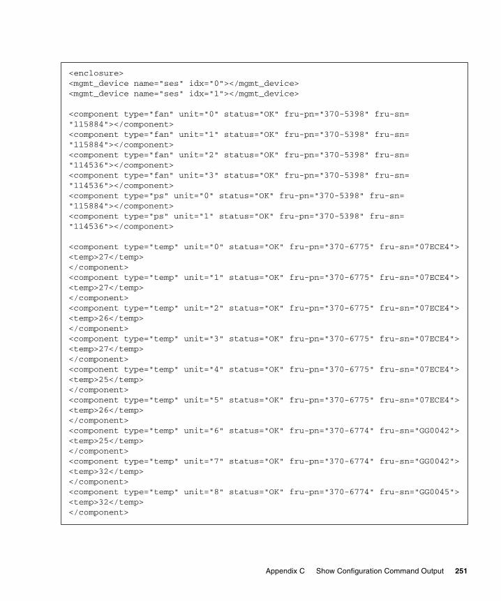
<enclosure><mgmt_device name="ses" idx="0"></mgmt_device><mgmt_device name="ses" idx="1"></mgmt_device>
<component type="fan" unit="0" status="OK" fru-pn="370-5398" fru-sn="115884"></component><component type="fan" unit="1" status="OK" fru-pn="370-5398" fru-sn="115884"></component><component type="fan" unit="2" status="OK" fru-pn="370-5398" fru-sn="114536"></component><component type="fan" unit="3" status="OK" fru-pn="370-5398" fru-sn="114536"></component><component type="ps" unit="0" status="OK" fru-pn="370-5398" fru-sn="115884"></component><component type="ps" unit="1" status="OK" fru-pn="370-5398" fru-sn="114536"></component>
<component type="temp" unit="0" status="OK" fru-pn="370-6775" fru-sn="07ECE4"><temp>27</temp></component><component type="temp" unit="1" status="OK" fru-pn="370-6775" fru-sn="07ECE4"><temp>27</temp></component><component type="temp" unit="2" status="OK" fru-pn="370-6775" fru-sn="07ECE4"><temp>26</temp></component><component type="temp" unit="3" status="OK" fru-pn="370-6775" fru-sn="07ECE4"><temp>27</temp></component><component type="temp" unit="4" status="OK" fru-pn="370-6775" fru-sn="07ECE4"><temp>25</temp></component><component type="temp" unit="5" status="OK" fru-pn="370-6775" fru-sn="07ECE4"><temp>26</temp></component><component type="temp" unit="6" status="OK" fru-pn="370-6774" fru-sn="GG0042"><temp>25</temp></component><component type="temp" unit="7" status="OK" fru-pn="370-6774" fru-sn="GG0042"><temp>32</temp></component><component type="temp" unit="8" status="OK" fru-pn="370-6774" fru-sn="GG0045"><temp>32</temp></component>
Appendix C Show Configuration Command Output 251
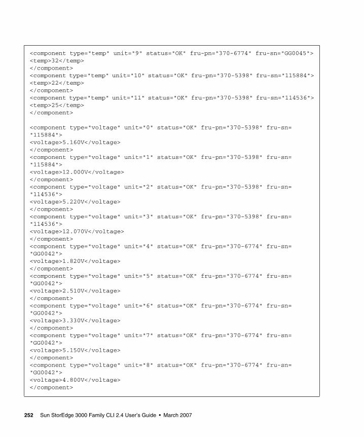
<component type="temp" unit="9" status="OK" fru-pn="370-6774" fru-sn="GG0045"><temp>32</temp></component><component type="temp" unit="10" status="OK" fru-pn="370-5398" fru-sn="115884"><temp>22</temp></component><component type="temp" unit="11" status="OK" fru-pn="370-5398" fru-sn="114536"><temp>25</temp></component>
<component type="voltage" unit="0" status="OK" fru-pn="370-5398" fru-sn="115884"><voltage>5.160V</voltage></component><component type="voltage" unit="1" status="OK" fru-pn="370-5398" fru-sn="115884"><voltage>12.000V</voltage></component><component type="voltage" unit="2" status="OK" fru-pn="370-5398" fru-sn="114536"><voltage>5.220V</voltage></component><component type="voltage" unit="3" status="OK" fru-pn="370-5398" fru-sn="114536"><voltage>12.070V</voltage></component><component type="voltage" unit="4" status="OK" fru-pn="370-6774" fru-sn="GG0042"><voltage>1.820V</voltage></component><component type="voltage" unit="5" status="OK" fru-pn="370-6774" fru-sn="GG0042"><voltage>2.510V</voltage></component><component type="voltage" unit="6" status="OK" fru-pn="370-6774" fru-sn="GG0042"><voltage>3.330V</voltage></component><component type="voltage" unit="7" status="OK" fru-pn="370-6774" fru-sn="GG0042"><voltage>5.150V</voltage></component><component type="voltage" unit="8" status="OK" fru-pn="370-6774" fru-sn="GG0042"><voltage>4.800V</voltage></component>
252 Sun StorEdge 3000 Family CLI 2.4 User’s Guide • March 2007
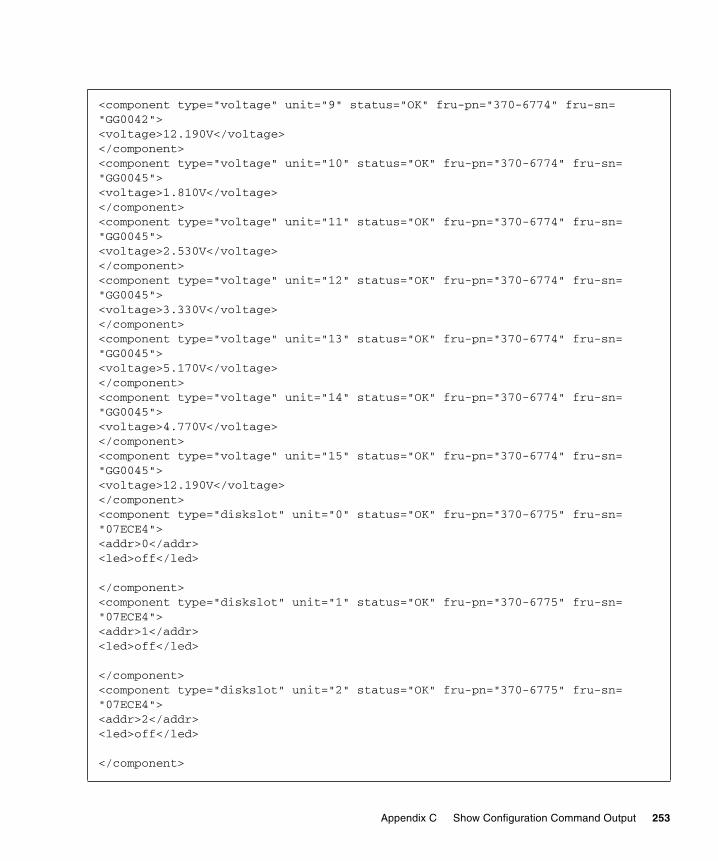
<component type="voltage" unit="9" status="OK" fru-pn="370-6774" fru-sn="GG0042"><voltage>12.190V</voltage></component><component type="voltage" unit="10" status="OK" fru-pn="370-6774" fru-sn="GG0045"><voltage>1.810V</voltage></component><component type="voltage" unit="11" status="OK" fru-pn="370-6774" fru-sn="GG0045"><voltage>2.530V</voltage></component><component type="voltage" unit="12" status="OK" fru-pn="370-6774" fru-sn="GG0045"><voltage>3.330V</voltage></component><component type="voltage" unit="13" status="OK" fru-pn="370-6774" fru-sn="GG0045"><voltage>5.170V</voltage></component><component type="voltage" unit="14" status="OK" fru-pn="370-6774" fru-sn="GG0045"><voltage>4.770V</voltage></component><component type="voltage" unit="15" status="OK" fru-pn="370-6774" fru-sn="GG0045"><voltage>12.190V</voltage></component><component type="diskslot" unit="0" status="OK" fru-pn="370-6775" fru-sn="07ECE4"><addr>0</addr><led>off</led>
</component><component type="diskslot" unit="1" status="OK" fru-pn="370-6775" fru-sn="07ECE4"><addr>1</addr><led>off</led>
</component><component type="diskslot" unit="2" status="OK" fru-pn="370-6775" fru-sn="07ECE4"><addr>2</addr><led>off</led>
</component>
Appendix C Show Configuration Command Output 253

<component type="diskslot" unit="3" status="OK" fru-pn="370-6775" fru-sn="07ECE4"><addr>3</addr><led>off</led>
</component><component type="diskslot" unit="4" status="OK" fru-pn="370-6775" fru-sn="07ECE4"><addr>4</addr><led>off</led>
</component><component type="diskslot" unit="5" status="OK" fru-pn="370-6775" fru-sn="07ECE4"><addr>5</addr><led>off</led>
</component><component type="diskslot" unit="6" status="OK" fru-pn="370-6775" fru-sn="07ECE4"><addr>6</addr><led>off</led>
</component><component type="diskslot" unit="7" status="OK" fru-pn="370-6775" fru-sn="07ECE4"><addr>7</addr><led>off</led>
</component><component type="diskslot" unit="8" status="OK" fru-pn="370-6775" fru-sn="07ECE4"><addr>8</addr><led>off</led>
</component><component type="diskslot" unit="9" status="Absent" fru-pn="370-6775" fru-sn="07ECE4"><addr>9</addr><led>off</led>
</component><component type="diskslot" unit="10" status="OK" fru-pn="370-6775" fru-sn="07ECE4"><addr>10</addr><led>off</led>
254 Sun StorEdge 3000 Family CLI 2.4 User’s Guide • March 2007

</component><component type="diskslot" unit="11" status="OK" fru-pn="370-6775" fru-sn="07ECE4"><addr>11</addr><led>off</led>
</component></enclosure><ses><idx>1</idx><ch>3</ch><id>12</id><chassis>07ECE4</chassis><vendor_product_id>SUN StorEdge 3511F D</vendor_product_id><rev>0420</rev><pld>1100</pld><wwnn>205000C0FF07ECE4</wwnn><wwpn>225000C0FF07ECE4</wwpn><topology>loopb</topology></ses><port_wwns><port_wwn><idx>0</idx><ch>0</ch><id>40</id><wwnn>216000C0FF8927C0</wwnn></port_wwn><port_wwn><idx>0</idx><ch>1</ch><id>42</id><wwnn>226000C0FFA927C0</wwnn></port_wwn><port_wwn><idx>4</idx><ch>4</ch><id>44</id><wwnn>256000C0FFC927C0</wwnn></port_wwn><port_wwn><idx>1</idx><ch>5</ch><id>46</id><wwnn>266000C0FFE927C0</wwnn></port_wwn>
Appendix C Show Configuration Command Output 255

</port_wwns><inter_controller_link><idx>0</idx><slot>upper</slot><ch>0</ch><ch_mode>host channel</ch_mode><bypass_status>N/A</bypass_status></inter_controller_link><inter_controller_link><idx>1</idx><slot>lower</slot><ch>0</ch><ch_mode>host channel</ch_mode><bypass_status>N/A</bypass_status></inter_controller_link><inter_controller_link><idx>2</idx><slot>upper</slot><ch>1</ch><ch_mode>host channel</ch_mode><bypass_status>N/A</bypass_status></inter_controller_link><inter_controller_link><idx>3</idx><slot>lower</slot><ch>1</ch><ch_mode>host channel</ch_mode><bypass_status>N/A</bypass_status></inter_controller_link><inter_controller_link><idx>4</idx><slot>upper</slot><ch>4</ch><ch_mode>host channel</ch_mode><bypass_status>N/A</bypass_status></inter_controller_link><inter_controller_link><idx>5</idx><slot>lower</slot><ch>4</ch><ch_mode>host channel</ch_mode><bypass_status>N/A</bypass_status></inter_controller_link>
256 Sun StorEdge 3000 Family CLI 2.4 User’s Guide • March 2007

<inter_controller_link><idx>6</idx><slot>upper</slot><ch>5</ch><ch_mode>host channel</ch_mode><bypass_status>N/A</bypass_status></inter_controller_link><inter_controller_link><idx>7</idx><slot>lower</slot><ch>5</ch><ch_mode>host channel</ch_mode><bypass_status>N/A</bypass_status></inter_controller_link><battery_status><name>Upper Battery</name><type>N/A</type><manufacturing_date>N/A</manufacturing_date><placed_in_service>N/A</placed_in_service><status>N/A</status></battery_status><battery_status><name>Lower Battery</name><type>N/A</type><manufacturing_date>N/A</manufacturing_date><placed_in_service>N/A</placed_in_service><status>N/A</status></battery_status><config_components><disk><ch>3</ch><target>0</target><status>USED</status><manufacturer>HITACHI</manufacturer><model>HDS7225SASUN250G</model><serial_number>VNRJ9HC6CU0TDM</serial_number><product_revision>A6DA</product_revision><wwnn>22E4000A33FFFF00</wwnn><capacity>232.88GB</capacity><remaining_size>232.63GB</remaining_size><Speed>200M</Speed><ld_id>00000000</ld_id><ld_idx>N/A</ld_idx></disk>
Appendix C Show Configuration Command Output 257

<disk><ch>3</ch><target>1</target><status>USED</status><manufacturer>HITACHI</manufacturer><model>HDS7225SASUN250G</model><serial_number>VNRJ3EC6CPSLMM</serial_number><product_revision>A6DA</product_revision><wwnn>22E4000A33FFFF01</wwnn><capacity>232.88GB</capacity><remaining_size>232.63GB</remaining_size><Speed>200M</Speed><ld_id>00000000</ld_id><ld_idx>N/A</ld_idx></disk><disk><ch>3</ch><target>2</target><status>USED</status><manufacturer>HITACHI</manufacturer><model>HDS7225SASUN250G</model><serial_number>VNRJ9HC6CTWR3M</serial_number><product_revision>A6DA</product_revision><wwnn>22E4000A33001C16</wwnn><capacity>232.88GB</capacity><remaining_size>232.63GB</remaining_size><Speed>200M</Speed><ld_id>00000000</ld_id><ld_idx>N/A</ld_idx></disk><disk><ch>3</ch><target>3</target><status>USED</status><manufacturer>HITACHI</manufacturer><model>HDS7225SASUN250G</model><serial_number>VNRJ9HC6CYA9GM</serial_number><product_revision>A6DA</product_revision><wwnn>22E4000A330014EB</wwnn><capacity>232.88GB</capacity><remaining_size>232.63GB</remaining_size><Speed>200M</Speed><ld_id>00000000</ld_id><ld_idx>N/A</ld_idx></disk>
258 Sun StorEdge 3000 Family CLI 2.4 User’s Guide • March 2007

<disk><ch>3</ch><target>4</target><status>USED</status><manufacturer>HITACHI</manufacturer><model>HDS7225SASUN250G</model><serial_number>VNRJ3EC6CHGG8M</serial_number><product_revision>A6DA</product_revision><wwnn>22E4000A33FFFF04</wwnn><capacity>232.88GB</capacity><remaining_size>232.63GB</remaining_size><Speed>200M</Speed><ld_id>00000000</ld_id><ld_idx>N/A</ld_idx></disk><disk><ch>3</ch><target>5</target><status>USED</status><manufacturer>HITACHI</manufacturer><model>HDS7225SBSUN250G</model><serial_number>VDB41BT4C5SY7C</serial_number><product_revision>A81A</product_revision><wwnn>22E4000A33000AD4</wwnn><capacity>232.88GB</capacity><remaining_size>232.63GB</remaining_size><Speed>200M</Speed><ld_id>00000000</ld_id><ld_idx>N/A</ld_idx></disk><disk><ch>3</ch><target>6</target><status>USED</status><manufacturer>HITACHI</manufacturer><model>HDS7225SASUN250G</model><serial_number>VNRJ3EC6CGXDVM</serial_number><product_revision>A6DA</product_revision><wwnn>22E4000A33FFFF06</wwnn><capacity>232.88GB</capacity><remaining_size>232.63GB</remaining_size><Speed>200M</Speed><ld_id>00000000</ld_id><ld_idx>N/A</ld_idx></disk>
Appendix C Show Configuration Command Output 259

<disk><ch>3</ch><target>7</target><status>USED</status><manufacturer>HITACHI</manufacturer><model>HDS7225SASUN250G</model><serial_number>VNRJ9HC6CTXK3M</serial_number><product_revision>A6DA</product_revision><wwnn>22E4000A33001E0A</wwnn><capacity>232.88GB</capacity><remaining_size>232.63GB</remaining_size><Speed>200M</Speed><ld_id>00000000</ld_id><ld_idx>N/A</ld_idx></disk><disk><ch>3</ch><target>8</target><status>USED</status><manufacturer>HITACHI</manufacturer><model>HDS7225SASUN250G</model><serial_number>VNRJ3EC6CHJ90M</serial_number><product_revision>A6DA</product_revision><wwnn>22E4000A33FFFF08</wwnn><capacity>232.88GB</capacity><remaining_size>232.63GB</remaining_size><Speed>200M</Speed><ld_id>00000000</ld_id><ld_idx>N/A</ld_idx></disk><disk><ch>3</ch><target>9</target><status>ONLINE</status><manufacturer>HITACHI</manufacturer><model>HDS7250SASUN500G</model><serial_number>KRVN63ZAGM6VND</serial_number><product_revision>A20A</product_revision><wwnn>22E4000A3300D7FB</wwnn><capacity>465.76GB</capacity><remaining_size>465.51GB</remaining_size><Speed>200M</Speed><ld_id>460FDB54</ld_id><ld_idx>2</ld_idx></disk>
260 Sun StorEdge 3000 Family CLI 2.4 User’s Guide • March 2007

<disk><ch>3</ch><target>10</target><status>STAND-BY</status><manufacturer>HITACHI</manufacturer><model>HDS7225SASUN250G</model><serial_number>VNRJ3EC6CH1DJM</serial_number><product_revision>A6DA</product_revision><wwnn>FFFC000A33FFFF0A</wwnn><capacity>232.88GB</capacity><remaining_size>232.63GB</remaining_size><Speed>200M</Speed><ld_id>00000000</ld_id><ld_idx>N/A</ld_idx></disk><disk><ch>3</ch><target>11</target><status>STAND-BY</status><manufacturer>HITACHI</manufacturer><model>HDS7225SASUN250G</model><serial_number>VNRJ7HC6D1X0VT</serial_number><product_revision>A6DA</product_revision><wwnn>22E4000A33002E60</wwnn><capacity>232.88GB</capacity><remaining_size>232.63GB</remaining_size><Speed>200M</Speed><ld_id>00000000</ld_id><ld_idx>N/A</ld_idx></disk><disk><ch>3</ch><target>13</target><status>ONLINE</status><manufacturer>HITACHI</manufacturer><model>HDS7250SASUN500G</model><serial_number>KRVN63ZAGJYT8D</serial_number><product_revision>A20A</product_revision><wwnn>22E4000A3300D7F9</wwnn><capacity>465.76GB</capacity><remaining_size>465.51GB</remaining_size><Speed>200M</Speed><ld_id>7C01DB6C</ld_id><ld_idx>0</ld_idx></disk>
Appendix C Show Configuration Command Output 261

<disk><ch>3</ch><target>14</target><status>ONLINE</status><manufacturer>HITACHI</manufacturer><model>HDS7250SASUN500G</model><serial_number>KRVN63ZAGM487D</serial_number><product_revision>A20A</product_revision><wwnn>22E4000A3300D7FE</wwnn><capacity>465.76GB</capacity><remaining_size>465.51GB</remaining_size><Speed>200M</Speed><ld_id>7C01DB6C</ld_id><ld_idx>0</ld_idx></disk><disk><ch>3</ch><target>16</target><status>ONLINE</status><manufacturer>HITACHI</manufacturer><model>HDS7250SASUN500G</model><serial_number>KRVN63ZAGM48XD</serial_number><product_revision>A20A</product_revision><wwnn>22E4000A3300D7FC</wwnn><capacity>465.76GB</capacity><remaining_size>465.51GB</remaining_size><Speed>200M</Speed><ld_id>7C01DB6C</ld_id><ld_idx>0</ld_idx></disk><disk><ch>3</ch><target>17</target><status>ONLINE</status><manufacturer>HITACHI</manufacturer><model>HDS7250SASUN500G</model><serial_number>KRVN63ZAGM3XUD</serial_number><product_revision>A20A</product_revision><wwnn>22E4000A3300D7F5</wwnn><capacity>465.76GB</capacity><remaining_size>465.51GB</remaining_size><Speed>200M</Speed><ld_id>64A046F7</ld_id><ld_idx>1</ld_idx></disk>
262 Sun StorEdge 3000 Family CLI 2.4 User’s Guide • March 2007

<disk><ch>3</ch><target>18</target><status>ONLINE</status><manufacturer>HITACHI</manufacturer><model>HDS7250SASUN500G</model><serial_number>KRVN63ZAGM49TD</serial_number><product_revision>A20A</product_revision><wwnn>22E4000A3300D800</wwnn><capacity>465.76GB</capacity><remaining_size>465.51GB</remaining_size><Speed>200M</Speed><ld_id>64A046F7</ld_id><ld_idx>1</ld_idx></disk><disk><ch>3</ch><target>19</target><status>ONLINE</status><manufacturer>HITACHI</manufacturer><model>HDS7250SASUN500G</model><serial_number>KRVN63ZAGM8N3D</serial_number><product_revision>A20A</product_revision><wwnn>22E4000A3300D7FA</wwnn><capacity>465.76GB</capacity><remaining_size>465.51GB</remaining_size><Speed>200M</Speed><ld_id>64A046F7</ld_id><ld_idx>1</ld_idx></disk><disk><ch>3</ch><target>20</target><status>ONLINE</status><manufacturer>HITACHI</manufacturer><model>HDS7250SASUN500G</model><serial_number>KRVN63ZAGM3XTD</serial_number><product_revision>A20A</product_revision><wwnn>22E4000A3300D7FF</wwnn><capacity>465.76GB</capacity><remaining_size>465.51GB</remaining_size><Speed>200M</Speed><ld_id>460FDB54</ld_id><ld_idx>2</ld_idx></disk>
Appendix C Show Configuration Command Output 263
<disk><ch>3</ch><target>21</target><status>ONLINE</status><manufacturer>HITACHI</manufacturer><model>HDS7250SASUN500G</model><serial_number>KRVN63ZAGM3VND</serial_number><product_revision>A20A</product_revision><wwnn>22E4000A3300D7FD</wwnn><capacity>465.76GB</capacity><remaining_size>465.51GB</remaining_size><Speed>200M</Speed><ld_id>460FDB54</ld_id><ld_idx>2</ld_idx></disk><disk><ch>3</ch><target>22</target><status>ONLINE</status><manufacturer>HITACHI</manufacturer><model>HDS7250SASUN500G</model><serial_number>KRVN63ZAGM72UD</serial_number><product_revision>A20A</product_revision><wwnn>22E4000A3300D7F7</wwnn><capacity>465.76GB</capacity><remaining_size>465.51GB</remaining_size><Speed>200M</Speed><ld_id>460FDB54</ld_id><ld_idx>2</ld_idx></disk><disk><ch>3</ch><target>23</target><status>ONLINE</status><manufacturer>HITACHI</manufacturer><model>HDS7250SASUN500G</model><serial_number>KRVN63ZAGL2HGD</serial_number><product_revision>A20A</product_revision><wwnn>22E4000A3300D7F8</wwnn><capacity>465.76GB</capacity><remaining_size>465.51GB</remaining_size><Speed>200M</Speed><ld_id>460FDB54</ld_id><ld_idx>2</ld_idx></disk>
264 Sun StorEdge 3000 Family CLI 2.4 User’s Guide • March 2007

<disk><ch>3</ch><target>24</target><status>ONLINE</status><manufacturer>HITACHI</manufacturer><model>HDS7250SASUN500G</model><serial_number>KRVN63ZAGM8DGD</serial_number><product_revision>A20A</product_revision><wwnn>22E4000A3300D7F6</wwnn><capacity>465.76GB</capacity><remaining_size>465.51GB</remaining_size><Speed>200M</Speed><ld_id>460FDB54</ld_id><ld_idx>2</ld_idx></disk></config_components><hostwwns></hostwwns><total_sata_routers>2</total_sata_routers><sata_router encl_id="0" encl_sn="07ECE4" ch="2" slot="upper" rev="DP0579 " boot_rev="0548" csb="0500" hw_rev="11" st_rev="0552"></sata_router><sata_router encl_id="0" encl_sn="07ECE4" ch="3" slot="lower" rev="DP0579 " boot_rev="0548" csb="0500" hw_rev="11" st_rev="0552"></sata_router><total_sata_mux>23</total_sata_mux><sata_mux ch="3" id="0" mux_sn="n/a" mux_type="A/A" pc150_rev="BB0D" pc150_boot="0300"></sata_mux><sata_mux ch="3" id="1" mux_sn="n/a" mux_type="A/A" pc150_rev="BB42" pc150_boot="0300"></sata_mux><sata_mux ch="3" id="2" mux_sn="001C16" mux_type="A/A" pc150_rev="BB42" pc150_boot="0300"></sata_mux><sata_mux ch="3" id="3" mux_sn="0014EB" mux_type="A/A" pc150_rev="BB42" pc150_boot="0300"></sata_mux><sata_mux ch="3" id="4" mux_sn="n/a" mux_type="A/A" pc150_rev="BB42" pc150_boot="0300"></sata_mux><sata_mux ch="3" id="5" mux_sn="000AD4" mux_type="A/A" pc150_rev="BB42" pc150_boot="0300"></sata_mux><sata_mux ch="3" id="6" mux_sn="n/a" mux_type="A/A" pc150_rev="BB42" pc150_boot="0300"></sata_mux><sata_mux ch="3" id="7" mux_sn="001E0A" mux_type="A/A" pc150_rev="BB42" pc150_boot="0300"></sata_mux><sata_mux ch="3" id="8" mux_sn="n/a" mux_type="A/A" pc150_rev="BB42" pc150_boot="0300"></sata_mux><sata_mux ch="3" id="9" mux_sn="00D7FB" mux_type="A/A" pc150_rev="BB42" pc150_boot="0300"></sata_mux><sata_mux ch="3" id="10" mux_sn="n/a" mux_type="A/A" pc150_rev="BB45" pc150_boot="0300"></sata_mux>
Appendix C Show Configuration Command Output 265

<sata_mux ch="3" id="11" mux_sn="002E60" mux_type="A/A" pc150_rev="BB42" pc150_boot="0300"></sata_mux><sata_mux ch="3" id="13" mux_sn="00D7F9" mux_type="A/A" pc150_rev="BB42" pc150_boot="0300"></sata_mux><sata_mux ch="3" id="14" mux_sn="00D7FE" mux_type="A/A" pc150_rev="BB42" pc150_boot="0300"></sata_mux><sata_mux ch="3" id="16" mux_sn="00D7FC" mux_type="A/A" pc150_rev="BB42" pc150_boot="0300"></sata_mux><sata_mux ch="3" id="17" mux_sn="00D7F5" mux_type="A/A" pc150_rev="BB42" pc150_boot="0300"></sata_mux><sata_mux ch="3" id="18" mux_sn="00D800" mux_type="A/A" pc150_rev="BB42" pc150_boot="0300"></sata_mux><sata_mux ch="3" id="19" mux_sn="00D7FA" mux_type="A/A" pc150_rev="BB42" pc150_boot="0300"></sata_mux><sata_mux ch="3" id="20" mux_sn="00D7FF" mux_type="A/A" pc150_rev="BB42" pc150_boot="0300"></sata_mux><sata_mux ch="3" id="21" mux_sn="00D7FD" mux_type="A/A" pc150_rev="BB42" pc150_boot="0300"></sata_mux><sata_mux ch="3" id="22" mux_sn="00D7F7" mux_type="A/A" pc150_rev="BB42" pc150_boot="0300"></sata_mux><sata_mux ch="3" id="23" mux_sn="00D7F8" mux_type="A/A" pc150_rev="BB42" pc150_boot="0300"></sata_mux><sata_mux ch="3" id="24" mux_sn="00D7F6" mux_type="A/A" pc150_rev="BB42" pc150_boot="0300"></sata_mux><access_mode>out-of-band</access_mode><controller_date>Wed Feb 28 21:50:41 2007</controller_date><boot_time>Wed Feb 28 21:22:31 2007</boot_time><time_zone>GMT -05:15</time_zone><drive_side_statistics><device_statistics><channel>3</channel><id>0</id><type>SDISK</type><reset>0</reset><LinkFail>0</LinkFail><SyncLoss>0</SyncLoss><SignalLoss>0</SignalLoss><PrimitiveSequence>0</PrimitiveSequence><InvalidTransWords>0</InvalidTransWords><InvalidCRC>0</InvalidCRC></device_statistics>
266 Sun StorEdge 3000 Family CLI 2.4 User’s Guide • March 2007

<device_statistics><channel>3</channel><id>1</id><type>SDISK</type><reset>0</reset><LinkFail>0</LinkFail><SyncLoss>0</SyncLoss><SignalLoss>0</SignalLoss><PrimitiveSequence>0</PrimitiveSequence><InvalidTransWords>0</InvalidTransWords><InvalidCRC>0</InvalidCRC></device_statistics><device_statistics><channel>3</channel><id>2</id><type>SDISK</type><reset>0</reset><LinkFail>0</LinkFail><SyncLoss>0</SyncLoss><SignalLoss>0</SignalLoss><PrimitiveSequence>0</PrimitiveSequence><InvalidTransWords>0</InvalidTransWords><InvalidCRC>0</InvalidCRC></device_statistics><device_statistics><channel>3</channel><id>3</id><type>SDISK</type><reset>0</reset><LinkFail>0</LinkFail><SyncLoss>0</SyncLoss><SignalLoss>0</SignalLoss><PrimitiveSequence>0</PrimitiveSequence><InvalidTransWords>0</InvalidTransWords><InvalidCRC>0</InvalidCRC></device_statistics><device_statistics><channel>3</channel><id>4</id><type>SDISK</type><reset>0</reset>
Appendix C Show Configuration Command Output 267
<LinkFail>0</LinkFail><SyncLoss>0</SyncLoss><SignalLoss>0</SignalLoss><PrimitiveSequence>0</PrimitiveSequence><InvalidTransWords>0</InvalidTransWords><InvalidCRC>0</InvalidCRC></device_statistics><device_statistics><channel>3</channel><id>5</id><type>SDISK</type><reset>0</reset><LinkFail>0</LinkFail><SyncLoss>0</SyncLoss><SignalLoss>0</SignalLoss><PrimitiveSequence>0</PrimitiveSequence><InvalidTransWords>0</InvalidTransWords><InvalidCRC>0</InvalidCRC></device_statistics><device_statistics><channel>3</channel><id>6</id><type>SDISK</type><reset>0</reset><LinkFail>0</LinkFail><SyncLoss>0</SyncLoss><SignalLoss>0</SignalLoss><PrimitiveSequence>0</PrimitiveSequence><InvalidTransWords>0</InvalidTransWords><InvalidCRC>0</InvalidCRC></device_statistics><device_statistics><channel>3</channel><id>7</id><type>SDISK</type><reset>0</reset><LinkFail>0</LinkFail><SyncLoss>0</SyncLoss><SignalLoss>0</SignalLoss><PrimitiveSequence>0</PrimitiveSequence><InvalidTransWords>0</InvalidTransWords><InvalidCRC>0</InvalidCRC></device_statistics>
268 Sun StorEdge 3000 Family CLI 2.4 User’s Guide • March 2007

<device_statistics><channel>3</channel><id>8</id><type>SDISK</type><reset>0</reset><LinkFail>0</LinkFail><SyncLoss>0</SyncLoss><SignalLoss>0</SignalLoss><PrimitiveSequence>0</PrimitiveSequence><InvalidTransWords>0</InvalidTransWords><InvalidCRC>0</InvalidCRC></device_statistics><device_statistics><channel>3</channel><id>9</id><type>SDISK</type><reset>0</reset><LinkFail>0</LinkFail><SyncLoss>0</SyncLoss><SignalLoss>0</SignalLoss><PrimitiveSequence>0</PrimitiveSequence><InvalidTransWords>0</InvalidTransWords><InvalidCRC>0</InvalidCRC></device_statistics><device_statistics><channel>3</channel><id>10</id><type>SDISK</type><reset>0</reset><LinkFail>0</LinkFail><SyncLoss>0</SyncLoss><SignalLoss>0</SignalLoss><PrimitiveSequence>0</PrimitiveSequence><InvalidTransWords>0</InvalidTransWords><InvalidCRC>0</InvalidCRC></device_statistics><device_statistics><channel>3</channel><id>11</id><type>SDISK</type><reset>0</reset><LinkFail>0</LinkFail><SyncLoss>0</SyncLoss><SignalLoss>0</SignalLoss><PrimitiveSequence>0</PrimitiveSequence>
Appendix C Show Configuration Command Output 269

<InvalidTransWords>0</InvalidTransWords><InvalidCRC>0</InvalidCRC></device_statistics><device_statistics><channel>3</channel><id>13</id><type>RAID</type><reset>0</reset><LinkFail>0</LinkFail><SyncLoss>0</SyncLoss><SignalLoss>0</SignalLoss><PrimitiveSequence>0</PrimitiveSequence><InvalidTransWords>0</InvalidTransWords><InvalidCRC>0</InvalidCRC></device_statistics><device_statistics><channel>3</channel><id>14</id><type>RAID</type><reset>0</reset><LinkFail>0</LinkFail><SyncLoss>0</SyncLoss><SignalLoss>0</SignalLoss><PrimitiveSequence>0</PrimitiveSequence><InvalidTransWords>0</InvalidTransWords><InvalidCRC>0</InvalidCRC></device_statistics><device_statistics><channel>3</channel><id>16</id><type>SDISK</type><reset>0</reset><LinkFail>0</LinkFail><SyncLoss>0</SyncLoss><SignalLoss>0</SignalLoss><PrimitiveSequence>0</PrimitiveSequence><InvalidTransWords>0</InvalidTransWords><InvalidCRC>0</InvalidCRC></device_statistics><device_statistics><channel>3</channel><id>17</id><type>SDISK</type><reset>0</reset>
270 Sun StorEdge 3000 Family CLI 2.4 User’s Guide • March 2007

<LinkFail>0</LinkFail><SyncLoss>0</SyncLoss><SignalLoss>0</SignalLoss><PrimitiveSequence>0</PrimitiveSequence><InvalidTransWords>0</InvalidTransWords><InvalidCRC>0</InvalidCRC></device_statistics><device_statistics><channel>3</channel><id>18</id><type>SDISK</type><reset>0</reset><LinkFail>0</LinkFail><SyncLoss>0</SyncLoss><SignalLoss>0</SignalLoss><PrimitiveSequence>0</PrimitiveSequence><InvalidTransWords>0</InvalidTransWords><InvalidCRC>0</InvalidCRC></device_statistics><device_statistics><channel>3</channel><id>19</id><type>SDISK</type><reset>0</reset><LinkFail>0</LinkFail><SyncLoss>0</SyncLoss><SignalLoss>0</SignalLoss><PrimitiveSequence>0</PrimitiveSequence><InvalidTransWords>0</InvalidTransWords><InvalidCRC>0</InvalidCRC></device_statistics><device_statistics><channel>3</channel><id>20</id><type>SDISK</type><reset>0</reset><LinkFail>0</LinkFail><SyncLoss>0</SyncLoss><SignalLoss>0</SignalLoss><PrimitiveSequence>0</PrimitiveSequence><InvalidTransWords>0</InvalidTransWords><InvalidCRC>0</InvalidCRC></device_statistics><device_statistics><channel>3</channel>
Appendix C Show Configuration Command Output 271

<id>21</id><type>SDISK</type><reset>0</reset><LinkFail>0</LinkFail><SyncLoss>0</SyncLoss><SignalLoss>0</SignalLoss><PrimitiveSequence>0</PrimitiveSequence><InvalidTransWords>0</InvalidTransWords><InvalidCRC>0</InvalidCRC></device_statistics><device_statistics><channel>3</channel><id>22</id><type>SDISK</type><reset>0</reset><LinkFail>0</LinkFail><SyncLoss>0</SyncLoss><SignalLoss>0</SignalLoss><PrimitiveSequence>0</PrimitiveSequence><InvalidTransWords>0</InvalidTransWords><InvalidCRC>0</InvalidCRC></device_statistics><device_statistics><channel>3</channel><id>23</id><type>SDISK</type><reset>0</reset><LinkFail>0</LinkFail><SyncLoss>0</SyncLoss><SignalLoss>0</SignalLoss><PrimitiveSequence>0</PrimitiveSequence><InvalidTransWords>0</InvalidTransWords><InvalidCRC>0</InvalidCRC></device_statistics><device_statistics><channel>3</channel><id>14</id><type>RAID</type><reset>2</reset><LinkFail>0</LinkFail><SyncLoss>65562</SyncLoss><SignalLoss>65600</SignalLoss><PrimitiveSequence>0</PrimitiveSequence>
272 Sun StorEdge 3000 Family CLI 2.4 User’s Guide • March 2007
<InvalidTransWords>874</InvalidTransWords><InvalidCRC>0</InvalidCRC></device_statistics><device_statistics><channel>3</channel><id>15</id><type>RAID</type><reset>2</reset><LinkFail>0</LinkFail><SyncLoss>0</SyncLoss><SignalLoss>0</SignalLoss><PrimitiveSequence>0</PrimitiveSequence><InvalidTransWords>0</InvalidTransWords><InvalidCRC>0</InvalidCRC></device_statistics></drive_side_statistics><drive_side_statistics><sata_device_statistics><channel>3</channel><id>0</id><type>SDISK</type><SignalLoss>0</SignalLoss><InvalidTransWords>0</InvalidTransWords><InvalidCRC>0</InvalidCRC></sata_device_statistics><sata_device_statistics><channel>3</channel><id>1</id><type>SDISK</type><SignalLoss>0</SignalLoss><InvalidTransWords>0</InvalidTransWords><InvalidCRC>0</InvalidCRC></sata_device_statistics><sata_device_statistics><channel>3</channel><id>2</id><type>SDISK</type><SignalLoss>0</SignalLoss><InvalidTransWords>0</InvalidTransWords><InvalidCRC>0</InvalidCRC></sata_device_statistics><sata_device_statistics><channel>3</channel>
Appendix C Show Configuration Command Output 273

<id>3</id><type>SDISK</type><SignalLoss>0</SignalLoss><InvalidTransWords>0</InvalidTransWords><InvalidCRC>0</InvalidCRC></sata_device_statistics><sata_device_statistics><channel>3</channel><id>4</id><type>SDISK</type><SignalLoss>0</SignalLoss><InvalidTransWords>0</InvalidTransWords><InvalidCRC>0</InvalidCRC></sata_device_statistics><sata_device_statistics><channel>3</channel><id>5</id><type>SDISK</type><SignalLoss>0</SignalLoss><InvalidTransWords>0</InvalidTransWords><InvalidCRC>0</InvalidCRC></sata_device_statistics><sata_device_statistics><channel>3</channel><id>6</id><type>SDISK</type><SignalLoss>0</SignalLoss><InvalidTransWords>0</InvalidTransWords><InvalidCRC>0</InvalidCRC></sata_device_statistics><sata_device_statistics><channel>3</channel><id>7</id><type>SDISK</type><SignalLoss>0</SignalLoss><InvalidTransWords>0</InvalidTransWords><InvalidCRC>0</InvalidCRC></sata_device_statistics><sata_device_statistics><channel>3</channel><id>8</id><type>SDISK</type><SignalLoss>0</SignalLoss><InvalidTransWords>0</InvalidTransWords><InvalidCRC>0</InvalidCRC></sata_device_statistics>
274 Sun StorEdge 3000 Family CLI 2.4 User’s Guide • March 2007

<sata_device_statistics><channel>3</channel><id>9</id><type>SDISK</type><SignalLoss>0</SignalLoss><InvalidTransWords>0</InvalidTransWords><InvalidCRC>0</InvalidCRC></sata_device_statistics><sata_device_statistics><channel>3</channel><id>10</id><type>SDISK</type><SignalLoss>0</SignalLoss><InvalidTransWords>0</InvalidTransWords><InvalidCRC>0</InvalidCRC></sata_device_statistics><sata_device_statistics><channel>3</channel><id>11</id><type>SDISK</type><SignalLoss>0</SignalLoss><InvalidTransWords>0</InvalidTransWords><InvalidCRC>0</InvalidCRC></sata_device_statistics><sata_device_statistics><channel>3</channel><id>13</id><type>SDISK</type><SignalLoss>0</SignalLoss><InvalidTransWords>0</InvalidTransWords><InvalidCRC>0</InvalidCRC></sata_device_statistics><sata_device_statistics><channel>3</channel><id>14</id><type>SDISK</type><SignalLoss>0</SignalLoss><InvalidTransWords>0</InvalidTransWords><InvalidCRC>0</InvalidCRC></sata_device_statistics><sata_device_statistics><channel>3</channel>
Appendix C Show Configuration Command Output 275
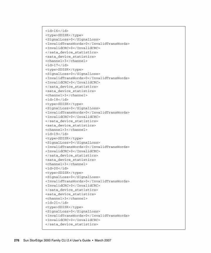
<id>16</id><type>SDISK</type><SignalLoss>0</SignalLoss><InvalidTransWords>0</InvalidTransWords><InvalidCRC>0</InvalidCRC></sata_device_statistics><sata_device_statistics><channel>3</channel><id>17</id><type>SDISK</type><SignalLoss>0</SignalLoss><InvalidTransWords>0</InvalidTransWords><InvalidCRC>0</InvalidCRC></sata_device_statistics><sata_device_statistics><channel>3</channel><id>18</id><type>SDISK</type><SignalLoss>0</SignalLoss><InvalidTransWords>0</InvalidTransWords><InvalidCRC>0</InvalidCRC></sata_device_statistics><sata_device_statistics><channel>3</channel><id>19</id><type>SDISK</type><SignalLoss>0</SignalLoss><InvalidTransWords>0</InvalidTransWords><InvalidCRC>0</InvalidCRC></sata_device_statistics><sata_device_statistics><channel>3</channel><id>20</id><type>SDISK</type><SignalLoss>0</SignalLoss><InvalidTransWords>0</InvalidTransWords><InvalidCRC>0</InvalidCRC></sata_device_statistics><sata_device_statistics><channel>3</channel><id>21</id><type>SDISK</type><SignalLoss>0</SignalLoss><InvalidTransWords>0</InvalidTransWords><InvalidCRC>0</InvalidCRC></sata_device_statistics>
276 Sun StorEdge 3000 Family CLI 2.4 User’s Guide • March 2007

<sata_device_statistics><channel>3</channel><id>22</id><type>SDISK</type><SignalLoss>0</SignalLoss><InvalidTransWords>0</InvalidTransWords><InvalidCRC>0</InvalidCRC></sata_device_statistics><sata_device_statistics><channel>3</channel><id>23</id><type>SDISK</type><SignalLoss>0</SignalLoss><InvalidTransWords>0</InvalidTransWords><InvalidCRC>0</InvalidCRC></sata_device_statistics><sata_device_statistics><channel>3</channel><id>24</id><type>SDISK</type><SignalLoss>0</SignalLoss><InvalidTransWords>0</InvalidTransWords><InvalidCRC>0</InvalidCRC></sata_device_statistics></drive_side_statistics></raidsystem></raidbaseview>
Appendix C Show Configuration Command Output 277

278 Sun StorEdge 3000 Family CLI 2.4 User’s Guide • March 2007

Glossary
The glossary lists acronyms and defines RAID terms found through the documentation. It also includes definitions of the operational states for disk drives and logical drives.
active-active controllers A pair of components, such as storage controllers in a failure-tolerant RAID
array, that share a task or set of tasks when both are functioning normally. When one component of the pair fails, the other takes the entire load. Dual active controllers are connected to the same set of devices and provide a combination of higher I/O performance and greater failure tolerance than a single controller.
ANSI American National Standards Institute.
ARP Address Resolution Protocol.
automatic rebuild A process in which data is automatically reconstructed after a drive failure and written to a standby (spare) drive. An automatic rebuild also occurs when a new drive is installed manually in place of a failed drive. If the rebuild process is interrupted by a reset, use the Manual Rebuild command from the firmware application to restart the rebuilding process.
block striping See striping.
block striping with dedicated parity (RAID 3) This technique breaks data into logical blocks, the size of a disk block,
and then stripes these blocks across several drives. One drive is dedicated to parity. In the event that a disk fails, the original data can be reconstructed using the parity information and the information on the remaining drives.
caching Allows data to be stored in a predesignated area of a disk or RAM (random access memory). Caching is used to speed up the operation of RAID arrays, disk drives, computers and servers, or other peripheral devices.
279
capacity The total number of physical drives available for data storage in a RAID array (logical drive). For example, if the capacity is N-1 and the total number of disk drives in a logical drives is six 36-Mbyte drives, the disk space available for storage is equal to five disk drives (5 x 36-Mbyte or 180 Mbyte).
CH Channel.
channel Any path used for the transfer of data and control information between storage devices and a storage controller or I/O adapter. Also refers to one SCSI bus on a disk array controller. Each disk array controller provides at least one channel.
CISPR International Special Committee on Radio Interference.
DHCP Dynamic Host Configuration Protocol.
disk mirroring See mirroring (RAID1).
EMC Electromagnetic compatibility.
EMU Event monitoring unit.
Fabric Fibre Channel network built around one or more switches.
Fabric switch A Fabric switch functions as a routing engine that actively directs data transfer from source to destination and arbitrates every connection. Bandwidth per node via a Fabric switch remains constant when more nodes are added, and a node on a switch port uses a data path of up to 100 Mbyte/sec to send or receive data.
failover A mode of operation for failure-tolerant arrays in which a component has failed and its function has been assumed by a redundant component.
fault tolerance The capacity to cope with internal hardware problems without interrupting the array’s data availability, often by using backup systems brought online when a failure is detected. Many arrays provide fault tolerance by using RAID architecture to give protection against loss of data when a single disk drive fails. Using RAID 1 (mirroring), RAID 3 or RAID 5 (striping with parity), or RAID 1+0 (mirroring and striping) techniques, the array controller can reconstruct data from a failed drive and write it to a standby or replacement drive.
fault-tolerant logical drive A logical drive that provides protection of data in the event of a single drive
failure by employing RAID 1, 1+0, 3, or 5.
FC-AL (Fibre Channel-Arbitrated Loop) FC-AL is implemented as either a loop or a Fabric. A loop can contain up to 126 nodes, accessible through only one or two servers.
Fibre Channel A cost-effective gigabit communications link deployed across a wide range of hardware.
Fibre Channel HBAs Fibre channel adapters of a host computer, server, or workstation.
280 Sun StorEdge 3000 Family CLI 2.4 User’s Guide • March 2007

Fibre hubs An Arbitrated Loop Hub is a wiring concentrator. “Arbitrated” means that all nodes communicating over this Fibre loop are sharing a 100 Mbyte/sec segment. Whenever more devices are added to a single segment, the bandwidth available to each node is further divided. A loop configuration allows different devices in the loop to be configured in a token ring style. With a Fibre hub, a Fibre loop can be rearranged in a star-like configuration because the hub itself contains port bypass circuitry that forms an internal loop. Bypass circuits can automatically reconfigure the loop once a device is removed or added without disrupting the physical connection to other devices.
FRU Field-replaceable unit.
Gbyte Gigabyte.
GBIC (Gigabit Interface Converter) A hot-swappable input/output device that plugs into a Gigabit Ethernet port or Fibre Channel.
global spare A spare drive that is available to all logical drives in an array. Spare drives can be part of automatic logical drive rebuild.
group A group is a data object that enables multiple servers to be contained under a single category. Groups are similar in concept to domains, and enable you to organize servers.
HBA Host bus adapter.
hot spare A drive in a RAID 1 or RAID 5 configuration that contains no data and acts as a standby in case another drive fails.
hot-swappable The ability of a field-replaceable unit (FRU) to be removed and replaced while the RAID array remains powered on and operational.
ID Identifier number.
IEC International Electrotechnical Commission.
initialization The process of writing a specific pattern to all data blocks on all drives in a logical drive. This process overwrites and destroys existing data on the disks and the logical drive. Initialization is required to make the entire logical drive consistent at the onset. Initialization ensures that any parity checks performed in the future are executed correctly.
JBOD (Just a Bunch of Disks) A storage device that consist of drives with no controllers.
LAN Local area network.
LD Logical drive.
logical drive A section of disk storage space, also referred to as a LUN, that is presented to the host operating system as a single physical drive. A logical drive might be located on one or more physical drives. Each controller can manage one to eight logical drives.
Glossary 281

LUN (logical unit number) The major and minor device numbers make up the logical unit numbering sequence for a particular device connected to a computer.
LUN mapping The ability to change the virtual LUN as presented to the server from storage. This enables such benefits as the ability of a server to boot from the SAN without requiring of a local disk drive. Each server requires LUN 0 to boot.
LUN masking The characteristic that enables an administrator to dynamically map an HBA to a specified LUN. This provides an individual server or multiple servers access to an individual drive or to multiple drives, and prohibits unwanted server access to the same drives.
LVD A low-noise, low-power, and low-amplitude signaling technology that enables data communication between a supported server and storage devices. LVD signaling uses two wires to drive one signal over copper wire and requires a cable that is no longer than 25 meters (82 feet).
management port The 10/100BASE-T Ethernet port that is used to configure a RAID array.
Mbyte Megabyte.
media scan A background process that continuously checks physical drives for bad blocks or other media errors.
mirroring (RAID 1) Data written to one disk drive is simultaneously written to another disk drive. If one disk fails, the other disk can be used to run the array and reconstruct the failed disk. The primary advantage of disk mirroring is 100 percent data redundancy. Since the disk is mirrored, it does not matter if one of the disks fails. Both disks contain the same data at all times and either can act as the operational disk.
Disk mirroring provides 100 percent redundancy but is expensive because each drive in the array is duplicated.
multiple-block striping with distributed
parity A RAID technique (RAID 5) that offers redundancy with the parity information distributed across all disks in the logical drive. Data and its parity are never stored on the same disk. In the event that a disk fails, the original data can be reconstructed using the parity information and the information on the remaining disks.
NDMP Network Data Management Protocol.
NVRAM (non-volatile random access memory) A memory unit equipped with a battery so that the data stays intact even after main power is switched off.
N port A Fibre Channel port in a point-to-point or Fabric connection.
OBP OpenBoot™ PROM (OBP). When you first start Solaris, it shows an OK prompt, which is the OBP. It is a command-line interface.
282 Sun StorEdge 3000 Family CLI 2.4 User’s Guide • March 2007

out-of-band Refers to the connections and devices that are not in the data path.
parity check A process whereby the integrity of the redundant data on fault-tolerant logical drives (RAID 1, 3, and 5) is checked. For RAID 3 and 5 configurations, the parity checking procedure on a logical drive recalculates the parity of data stripes in each of the logical drive’s RAID stripe sets and compares it with the stored parity. If a discrepancy is found, an error is reported and the new correct parity is substituted for the stored parity. For RAID 1 configurations, if an inconsistency is encountered, data is copied from the master disk to the slave disk. If a bad block is encountered when the parity is regenerated, the data is copied from the other disk, master or slave, to the reporting disk drive reallocating the bad block.
partner group A pair of interconnected controller units. Expansion units interconnected to the pair of controller units can also be part of the partner group.
PID Primary controller identifier number
PLA Programmable Logic Array. Offers flexible features for more complex designs.
PLD Programmable logic device. A generic term for an integrated circuit that can be programmed in a laboratory to perform complex functions.
RAID (redundant array of independent disks) An arrangement of two or more disk drives combined into a single virtual drive to provide more disk storage space, better performance and reliability, and redundant backup of data. Various combinations of these features are described by defined RAID levels. Arrays can support RAID 0, 1, 1+0, 3, and 5.
RAID Level Various techniques using combinations of mirroring, striping, duplexing, and parity to implement a RAID array are called RAID levels. Each technique uses a distinct algorithm to offer a mix of performance, reliability and cost.
RARP Reverse Address Resolution Protocol.
RAS Reliability, Availability, and Serviceability. These headings refer to a variety of features and initiatives all designed to maximize equipment uptime and mean time between failures, minimize downtime and the length of time necessary to repair failures, and eliminate or decrease single points of failure in favor of redundancy.
read policy A storage device parameter that determines whether the storage device holds data in cache before storing it to disk. The ability to hold data in cache while it is being written to disk can increase storage device speed during sequential reads.
rebuild The process of reconstructing the data that was on a disk before it failed. Rebuilding can be done only in arrays with data redundancy, such as RAID levels 1, 1+0, 3, and 5.
Glossary 283

rebuild priority Rebuild priority enables the RAID controller to serve other I/O requests while rebuilding the logical drives. Priority ranges from low, which uses the controller’s minimum resources to rebuild, to high, which uses the controller’s maximum resources to complete the rebuilding process.
SAN (storage area networking) A high-speed, open-standard, scalable network of storage devices and servers providing accelerated data access.
SCSI (Small Computer Systems Interface) An industry standard for connecting disk and tape devices to a workstation.
SES An interface to SCSI Enclosure Services devices. These devices sense and monitor physical conditions within an enclosure, and enable access to the status reporting and configuration features of the enclosure (such as indicator LEDs on the enclosure).
SID Secondary controller identifier number.
SMART (Self-Monitoring Analysis and Reporting Technology) The industry-standard reliability prediction indicator for both the IDE/ATA and SCSI hard disk drives. Hard disk drives with SMART offer early warning of some hard disk failures so critical data can be protected.
SMTP (Simple Mail Transfer Protocol) A protocol for sending email messages between servers and from mail clients to mail servers. The messages can then be retrieved with an email client using either POP or IMAP.
SNMP (Simple Network Management Protocol) A set of protocols for managing complex networks. SNMP works by sending messages, called protocol data units (PDUs), to different parts of a network. SNMP-compliant devices, called agents, store data about themselves in Management Information Bases (MIBs) and return this data to the SNMP requesters.
spanning Making use of the firmware’s striping capability to stripe data across two otherwise independent RAID logical drives. The two spanned logical drives are presented to the operating system as one logical drive.
standby drive A drive that is marked as a spare to support automatic data rebuilding after a physical drive associated with a logical drive fails. For a standby drive to take the place of another drive, it must be at least equal in size to the failed drive and all of the logical drives dependent on the failed disk must be redundant—RAID 1, 1+0, 3, and 5.
state The current operational status of a disk drive, a logical drive, or controller. The RAID array stores the states of drives, logical drives, and the controller in its nonvolatile memory. This information is retained across power interruptions.
stripe size This is the amount of data in kilobytes that is striped across each physical drive in a logical drive. Generally, large stripe sizes are more effective for arrays with sequential reads.
284 Sun StorEdge 3000 Family CLI 2.4 User’s Guide • March 2007

striping The storing of sequential blocks of incoming data on all the different physical drives in a logical drive.
This method of writing data increases the disk array throughput because multiple drives are working simultaneously, retrieving and storing. RAID 0, 1+0, 3, and 5 and all use striping.
terminator A part used to end a SCSI bus. Terminators prevent energy from reflecting back into a cable plant by absorbing the radio frequency signals.
UPS Uninterruptible Power Supply.
volume Also called a logical unit number or LUN, a volume is one or more drives that can be grouped into a unit for data storage.
write-back cache A cache-writing strategy in which the array controller receives the data to be written to disk, stores it in the memory buffer, and immediately sends the host operating system a signal that the write operation is complete, without waiting until the data is actually written to the disk drive. Within a short time, the controller, when not busy, writes the data to the disk drive.
write policy A cache-writing strategy used to control write operations. The write policy options are CIFS write-back and write-through cache.
write-through cache A cache-writing strategy in which the array controller writes the data to the disk drive before signaling the host operating system that the process is complete. Write-through cache has lower write operation and throughput performance than write-back cache, but it is the safer strategy, with minimum risk of data loss on power failure.
WWN (worldwide name) A globally unique, hard-coded and embedded number assigned by the manufacturer and registered under IEEE that is used to identify hardware.
Glossary 285

286 Sun StorEdge 3000 Family CLI 2.4 User’s Guide • March 2007
Index
Aabort clone command, 90abort create command, 122abort expand command, 123abort media-check command, 124abort parity-check command, 125abort rebuild command, 126about command, 18access mode, displaying, 33add disk command, 126alarm
muting for controller, 71silencing JBOD, 71
Bbad blocks, finding, 127
Ccache settings, 73, 81calculating maximum drive expand capacity, 135capacity
calculating maximum drive expand capacity, 135
channelconfiguring, 106drive parameters, setting, 108host parameters, setting, 110viewing host or drive, 113
chassis component status, 38check media command, 127check parity command, 128
checking parity, 128, 148clear events command, 63clone command, 91cloning
performing, 91stopping, 90viewing, 97
command keywords, 7command parameters, list of, xii, 185communication modes, 1configure channel command, 106configure global-spare command, 92configure local-spare command, 130configure network-interface command, 21configure partition command, 154controller
array name, 77component status, 47downloading configuration, 69downloading firmware, 175drive channel parameters, 115IP address, 28resetting, 72shutting down, 86, 88supplying password, 71uploading configuration, 89viewing date, 81viewing event log, 64, 65viewing name, 82
create host-wwn-name command, 23create logical-drive command, 131create logical-volume command, 163
287

Ddelete host-wwn-name command, 24delete logical-drive command, 134delete logical-volume command, 164device names
inband communication, 10out-of-band communication, 11
DHCP, 22, 26, 31, 50disk option, 8disks
adding, 126, 144capacity, 15device syntax, 12downloading firmware, 177scanning, 93verifying data on, 94, 97viewing, 98
download controller-configuration file command, 69
download controller-firmware command, 175download disk-firmware command, 177download nvram command, 49download pld-hardware command, 179download safte-firmware command, 180download sata-path-controller-firmware
command, 181download sata-router-firmware command, 182download ses-firmware command, 183drive parameters
setting, 108viewing, 108
DTD file, 215dynamic addressing, configuring, 22Dynamic Host Configuration Protocol, 22, 26, 31, 50
Eenvironmental sensors
chassis components, 38controller components, 47
error messages, 197event log
clearing, 63viewing, 64, 65
exit code, 6exit command, 18
expand command, 135expanding
capacity of logical drive or logical volume, 135
Ffail command, 70firmware
downloading for controller, 175downloading for disks, 177
FRUs, showing, 45FTP, enabling, 21
Gglobal spare
configuring, 92unconfiguring, 102
Hhelp command, 19help, accessing, 4host channels
configuring, 106viewing, 117
host LUN filters, naming hosts, 23host parameters
setting, 110viewing, 117
host WWNcreating, 23deleting, 24name entry, 23viewing, 27
Iinband communication
device names, 10disabling, 110security, 110
inquiry data, 82interactive command mode, 5IP address
setting, 23viewing, 28
JJBOD
288 Sun StorEdge 3000 Family CLI 2.4 User’s Guide • March 2007

device names, 11list of commands, 194SAF-TE information, 170silencing alarm, 71
Kkeywords, 7
LLAN interface, configuring, 21LEDs
illuminating, 95status, 101
list option, 8local spare
configuring, 130unconfiguring, 152
logical drivesadding disks, 126, 144checking parity, 148creating, 131deleting, 134expanding, 144identifier, 13index, 13initializing, 145rebuilding, 137, 149show disks in, 140shutting down, 151sizing, 135syntax, 13viewing, 142viewing in logical volume, 146write policy, 138
logical volumescreating, 163deleting, 164identifier, 14index, 14syntax, 14viewing, 146, 167write policy, 165
loop maps, viewing, 60loop mode, viewing, 115LUNs
filtering, 23viewing, 117
Mman pages, accessing, 4map partition command, 155maximum drive expand capacity, 135media scan, 127multiplexer (MUX) boards
downloading code to, 181viewing, 171
mute command, 71
Nnetmask, viewing, 28network parameters
configuring, 21viewing, 28
nvramdownloading, 49uploading file, 62
Ooob option, 2, 8optimization
random I/Ostripe size, 131
optimization settings, 73options, list of, xii, 185out-of-band communication
device names, 11management functions, 21
Pparameters, list of, xii, 185parity check
performing, 128viewing, 148
partitionsconfiguring, 154deleting, 154mapping, 155sizing, 154unmapping, 160viewing, 159viewing mapped, 117, 158
password command, 71password option, 10path controller firmware, downloading, 181
Index 289

peripheral deviceschassis sensor status, 38controller sensor status, 47
persistent events, viewing, 65physical disk syntax, 12point-to-point mode, viewing, 115port bypass circuit status, 118protocols
configuring, 21displaying, 30restricting, 25
Qquit command, 19
Rrandom I/O optimization
stripe size, 131RARP, 22rebuild command, 137reset controller command, 72Reverse Address Resolution Protocol, 22router
firmware, downloading, 182viewing, 172
RS-232 configurationsetting, 78
RS232 configurationviewing connection, 31
running CLI, 3
SSAF-TE
component status, 38downloading firmware, 180viewing, 170
SATA devicesdownloading path controller firmware for, 181downloading router firmware for, 182MUX boards, 171router, 172
scan disk command, 93SCSI inquiry data, 82security
disabling protocols, 25for inband access, 110
select command, 20SES device
component status, 38downloading firmware, 183viewing, 173
set auto-write-through-trigger command, 32set cache-parameters command, 73set controller-date command, 76set controller-name command, 77set disk-array command, 94set drive-parameters command, 108set host-parameters command, 110set inter-controller-link command, 112set led command, 95set logical-drive command, 138set logical-volume command, 165set protocol command, 25set rs232-configuration command, 78set unique identifier command, 80show access-mode command, 33show auto-write-through-trigger command, 34show bypass device command, 51show bypass RAID command, 54show bypass SFP command, 55show cache-parameters command, 81show channels command, 19, 113show clone command, 97show configuration command, 57, 207show controller-date command, 81show controller-name command, 82show disk-array command, 97show disks command, 98show disks logical-drive command, 140show drive-parameters command, 115show enclosure-status command, 38show events command, 64show frus command, 45show host-parameters command, 117show host-wwn-names command, 27show inquiry-data command, 82show ip-address command, 28show led-status command, 101show logical-drive command, 142
290 Sun StorEdge 3000 Family CLI 2.4 User’s Guide • March 2007

show logical-drives add-disk command, 144show logical-drives expanding command, 144show logical-drives initializing command, 145show logical-drives logical-volume command, 146show logical-drives parity-check command, 148show logical-drives rebuilding command, 149show logical-volume command, 167show loop-map command, 60show lun-maps command, 158show luns command, 117show media-check command, 149show network-parameters command, 28show partitions command, 159show peripheral-device-status command, 47show persistent-events command, 65show port-wwn command, 29show protocol command, 30show redundancy-mode command, 84show redundant-controller command, 86show rs232-configuration command, 31show safte-device command, 170show sata-mux command, 171show sata-router command, 172show ses-devices command, 173show shutdown-status command, 86show stripe-size-list command, 150show unique-identifier command, 87shutdown controller command, 88shutdown logical-drive command, 151single-command mode, 6SNMP, enabling, 21special characters, using, 5starting CLI, 3static addressing, configuring, 22stripe size
random optimization, 131sequential optimization, 131
stripe size, reviewing, 150superuser privileges, 1
TTelnet
enabling, 21inactivity period timeout, 25
viewing inactivity timeout value, 30troubleshooting, 197troubleshooting commands
show bypass device, 51show bypass RAID, 54show bypass SFP, 55show loop-map, 60
Uunconfigure global-spare command, 102unconfigure local-spare command, 152unfail command, 89unique identifier, setting, 80unmap partition command, 160upload controller-configuration file command, 89upload nvram command, 62
Vversion command, 20version option, 10
Wwrite policy
setting for logical drives, 131, 138setting globally, 73
write-back setting, 73write-through setting, 73
Xxml configuration report, 57xml DTD, 215xml output, 207xml output sample, 240
Index 291

292 Sun StorEdge 3000 Family CLI 2.4 User’s Guide • March 2007