sun storedge san 4.0 release field troubleshooting … microsystems, inc. 4150 network circle santa...
TRANSCRIPT
Sun Microsystems, Inc.4150 Network CircleSanta Clara, CA 95054 U.S.A.650-960-1300
Send comments about this document to: [email protected]
Sun StorEdge™ SAN 4.0 ReleaseField Troubleshooting Guide
Part No. 816-6580-11October 2002, Revision A

PleaseRecycle
Copyright 2002 Sun Microsystems, Inc., 4150 Network Circle •Santa Clara, CA 95054 USA. All rights reserved.
This product or document is protected by copyright and distributed under licenses restricting its use, copying, distribution, and decompilation.No part of this product or document may be reproduced in any form by any means without prior written authorization of Sun and its licensors,if any. Third-party software, including font technology, is copyrighted and licensed from Sun suppliers.
Parts of the product may be derived from Berkeley BSD systems, licensed from the University of California. UNIX is a registered trademark inthe U.S. and other countries, exclusively licensed through X/Open Company, Ltd. For Netscape Communicator™, the following notice applies:Copyright 1995 Netscape Communications Corporation. All rights reserved.
Sun, Sun Microsystems, the Sun logo, AnswerBook2, docs.sun.com, Sun StorEdge network FC switch-8, and Solaris are trademarks, registeredtrademarks, or service marks of Sun Microsystems, Inc. in the U.S. and other countries. All SPARC trademarks are used under license and aretrademarks or registered trademarks of SPARC International, Inc. in the U.S. and other countries. Products bearing SPARC trademarks arebased upon an architecture developed by Sun Microsystems, Inc.
The OPEN LOOK and Sun™ Graphical User Interface was developed by Sun Microsystems, Inc. for its users and licensees. Sun acknowledgesthe pioneering efforts of Xerox in researching and developing the concept of visual or graphical user interfaces for the computer industry. Sunholds a non-exclusive license from Xerox to the Xerox Graphical User Interface, which license also covers Sun’s licensees who implement OPENLOOK GUIs and otherwise comply with Sun’s written license agreements.
RESTRICTED RIGHTS: Use, duplication, or disclosure by the U.S. Government is subject to restrictions of FAR 52.227-14(g)(2)(6/87) andFAR 52.227-19(6/87), or DFAR 252.227-7015(b)(6/95) and DFAR 227.7202-3(a).
DOCUMENTATION IS PROVIDED “AS IS” AND ALL EXPRESS OR IMPLIED CONDITIONS, REPRESENTATIONS AND WARRANTIES,INCLUDING ANY IMPLIED WARRANTY OF MERCHANTABILITY, FITNESS FOR A PARTICULAR PURPOSE OR NON-INFRINGEMENT,ARE DISCLAIMED, EXCEPT TO THE EXTENT THAT SUCH DISCLAIMERS ARE HELD TO BE LEGALLY INVALID.
Copyright 2002 Sun Microsystems, Inc., 4150 Network Circle • Santa Clara, CA 95054 Etats-Unis. Tous droits réservés.
Ce produit ou document est protégé par un copyright et distribué avec des licences qui en restreignent l’utilisation, la copie, la distribution, et ladécompilation. Aucune partie de ce produit ou document ne peut être reproduite sous aucune forme, par quelque moyen que ce soit, sansl’autorisation préalable et écrite de Sun et de ses bailleurs de licence, s’il y en a. Le logiciel détenu par des tiers, et qui comprend la technologierelative aux polices de caractères, est protégé par un copyright et licencié par des fournisseurs de Sun.
Des parties de ce produit pourront être dérivées des systèmes Berkeley BSD licenciés par l’Université de Californie. UNIX est une marquedéposée aux Etats-Unis et dans d’autres pays et licenciée exclusivement par X/Open Company, Ltd. La notice suivante est applicable àNetscape Communicator™: Copyright 1995 Netscape Communications Corporation. Tous droits réservés.
Sun, Sun Microsystems, the Sun logo, AnswerBook2, docs.sun.com, Sun StorEdge network FC switch-8, et Solaris sont des marques de fabriqueou des marques déposées, ou marques de service, de Sun Microsystems, Inc. aux Etats-Unis et dans d’autres pays. Toutes les marques SPARCsont utilisées sous licence et sont des marques de fabrique ou des marques déposées de SPARC International, Inc. aux Etats-Unis et dansd’autres pays. Les produits portant les marques SPARC sont basés sur une architecture développée par Sun Microsystems, Inc.
L’interface d’utilisation graphique OPEN LOOK et Sun™ a été développée par Sun Microsystems, Inc. pour ses utilisateurs et licenciés. Sunreconnaît les efforts de pionniers de Xerox pour la recherche et le développement du concept des interfaces d’utilisation visuelle ou graphiquepour l’industrie de l’informatique. Sun détient une licence non exclusive de Xerox sur l’interface d’utilisation graphique Xerox, cette licencecouvrant également les licenciés de Sun qui mettent en place l’interface d’utilisation graphique OPEN LOOK et qui en outre se conforment auxlicences écrites de Sun.
CETTE PUBLICATION EST FOURNIE "EN L’ETAT" ET AUCUNE GARANTIE, EXPRESSE OU IMPLICITE, N’EST ACCORDEE, Y COMPRISDES GARANTIES CONCERNANT LA VALEUR MARCHANDE, L’APTITUDE DE LA PUBLICATION A REPONDRE A UNE UTILISATIONPARTICULIERE, OU LE FAIT QU’ELLE NE SOIT PAS CONTREFAISANTE DE PRODUIT DE TIERS. CE DENI DE GARANTIE NES’APPLIQUERAIT PAS, DANS LA MESURE OU IL SERAIT TENU JURIDIQUEMENT NUL ET NON AVENU.

Contents
Preface xi
1. Introduction 1
Document Scope 2
New Features of the Sun StorEdge SAN 4.0 Release 3
Cascading Switches (E_Ports) 7
2. Configurations 9
Supported Hardware 10
Supported Configurations 12
Operating Environments 12
Hosts 13
Host/Operating Environment Rules 14
Storage Arrays 14
Array Storage Rules 15
Host Bus Adapters 15
iii
Software Packages and Patches 16
▼ To generate the most recent patch list for a Sun Solaris Release 16
▼ To generate the most recent patch list for a specific Sun StorEdge SAN4.0 Release Configuration 16
Unbundled Software 17
Switches 18
Switch Port Types 19
New Sun StorEdge SAN 4.0 Release Port Types 19
Sun StorEdge and Brocade Communications Systems Port Descriptionsand Differences 19
Zones 21
Name Server Zones 21
Overlapping Zones 21
Zoning Rules 22
Configuration Guidelines 22
Switches 22
Zones and Arrays 22
Zones and Storage 23
Cascading Rules 23
Rules for Adding and Removing Devices While the Hosts are Online 23
Configuration Examples 24
Single Host Connected to One Storage Array 24
Single Host Connected to Multiple Storage Arrays 25
Multihost 27
iv Sun StorEdge SAN 4.0 Release Field Troubleshooting Guide • October 2002

3. Diagnostics 31
Diagnostic Tools 32
Storage Automated Diagnostic Environment Version 2.1 32
Storage Automated Diagnostic Environment Version 2.1 Functions 33
▼ To Access the Diagnostic Tests 35
Sun Explorer Data Collector (SUNWexplo) and T3Extractor 40
Explorer 40
T3Extractor 40
Diagnosing and Troubleshooting the Sun Switch 41
Using Switch Counter Information 41
qlctest Test 42
4. Troubleshooting Example 43
Example Configuration 44
Example Assumptions 45
Troubleshooting Outline 45
Troubleshooting Example of aHost–to–Switch Error 47
Determine the Error 47
Determine the Extent of the Problem 53
Check the Array Status 55
Check the Switch Status 56
Test the FRUs 57
Storage Automated Diagnostics Environment switchtest and qlctestTests 57
Storage Automated Diagnostics Environment linktest Test Output 58
Verify the Fix 61
Contents v
A. Brocade Communications Systems Upgrades and Installations 65
Installing a New SAN 66
Required Software Components 66
Downloading Patches and Packages 67
▼ To Verify Successful Patch Downloads 67
Installing the Software 69
▼ To Install the Software 70
Installing Firmware on Brocade Communications Systems SilkwormSwitches 72
▼ To Download Firmware from the Brocade Web Site 72
▼ To Install Firmware from UNIX (Solaris) 72
▼ To Install Firmware using FTP 74
Upgrading the SAN 76
Downloading Patches and Packages 76
Verifying Upgrade Compliance 76
▼ To Upgrade the Software 76
Volume Management 77
Sun StorEdge SAN 4.0 Release 77
cfgadm Plug-in Library Packages 78
Software Installation 79
▼ To Upgrade the Storage Automated Diagnostic Environment Version2.1 Package 79
B. Brocade Communications Systems Switch Troubleshooting 81
Related Documentation 82
Supported Configurations 83
QuickLoop 87
Current Issues with the Storage Automated Diagnostic Environment Version2.1 and Brocade Switches 87
vi Sun StorEdge SAN 4.0 Release Field Troubleshooting Guide • October 2002

Diagnostic Tools 87
Storage Automated Diagnostic Environment Version 2.1 and BrocadeSwitches 87
brocadetest(1M) 88
Other Diagnostic Tools 89
Sun StorEdge and Brocade Communications Systems Port Descriptions andDifferences 95
Accessing the Brocade Silkworm Switch 96
Power On Self Test (POST) 98
Removing Power 99
General Troubleshooting Procedures 101
Troubleshooting Case Study 103
Configuration 103
Storage Automated Diagnostic Environment Version 2.1 Topology 104
C. Brocade Communications Systems Error Messages 121
Error Message Formats 122
Front Panel Message Formats 122
▼ To Display Error Messages from the Front Panel 123
Diagnostic Error Message Formats 123
D. Converting Sun FC Switches Fibre Channel Addresses 139
Converting a Fabric Address into Fabric ID, Chassis ID, ASIC, Port, andAL_PA 140
Example 141
Contents vii

viii Sun StorEdge SAN 4.0 Release Field Troubleshooting Guide • October 2002

Figures
FIGURE 1-1 Switch and Interconnections 2
FIGURE 2-1 Single Host Connected to One Sun StorEdge T3 Array Enterprise Configuration 24
FIGURE 2-2 Single Host Connected to Multiple Sun StorEdge T3 Array Enterprise Configurations 26
FIGURE 2-3 Two Hosts Connected to Four Sun StorEdge T3 Array Enterprise Configurations 28
FIGURE 2-4 Two Hosts Connected to Sun StorEdge T3 Array Partner Group—Each Host with SeparateNon-shared Storage 29
FIGURE 3-1 Storage Automated Diagnostic Environment Version 2.1 Home Window 32
FIGURE 3-2 Storage Automated Diagnostic Environment—Diagnose Tab Selected 35
FIGURE 3-3 Storage Automated Diagnostic Environment—Diagnostic Tests Window 36
FIGURE 3-4 Storage Automated Diagnostic Environment—Test from Topology Window 37
FIGURE 3-5 Storage Automated Diagnostic Environment—Test from Topology Window with BackgroundReduced to 66% 38
FIGURE 3-6 Storage Automated Diagnostic Environment—Test from Topology Window with BackgroundReduced to 66% and Components Arranged for Viewing 39
FIGURE 4-1 Troubleshooting Example Viewed with Storage Automated Diagnostic Environment Version2.1 44
FIGURE 4-2 Troubleshooting Example View 2 53
FIGURE 4-3 Troubleshooting Example View 3 56
FIGURE B-1 Brocade Webtools GUI 97
FIGURE B-2 Storage Automated Diagnostic Environment Version 2.1—Test from Topology Window 104
FIGURE B-3 Storage Automated Diagnostic Environment Alert 107
FIGURE B-4 Storage Automated Diagnostic Environment version 2.1 Link Test Display 112
vii
FIGURE B-5 Test Result Details with Remedy Request 113
FIGURE B-6 Test Result Details Showing a Successful Test 114
FIGURE B-7 Continued Link Test Example Results 115
FIGURE B-8 Continued Link Test Example Results 116
FIGURE B-9 Storage Automated Diagnostic Environment Version 2.1—Test from Topology Window 119
viii Sun StorEdge SAN 4.0 Release Field Troubleshooting Guide • October 2002

Tables
TABLE 1-1 Comparison of the SAN 3.0 and SAN 4.0 Releases 3
TABLE 2-1 Supported Hardware 10
TABLE 2-2 Sun StorEdge SAN 4.0 Release Sun Operating Environment Compatibility Matrix 12
TABLE 2-3 Sun StorEdge SAN 4.0 Release Server Compatibility Matrix 13
TABLE 2-4 Sun StorEdge SAN 4.0 Release Storage Array Compatibility Matrix 14
TABLE 2-5 Supported Features of the Sun StorEdge T3 Array 15
TABLE 2-6 Sun StorEdge SAN 4.0 Release HBA Compatibility Matrix 15
TABLE 2-7 Unbundled Software 17
TABLE 2-8 Sun StorEdge SAN 4.0 Release Optional Software Packages Compatibility Matrix 18
TABLE 2-9 Sun StorEdge and Brocade Communications Systems Port Descriptions 19
TABLE 2-10 Differences Between Sun StorEdge and Brocade Port Communications Systems PortNomenclature 20
TABLE 2-11 Arrays, Zones, and Initiators 23
TABLE A-1 Software Download Sites 67
TABLE A-2 Software Installation Sequence 69
TABLE B-1 SAN Supportability Matrix with Solaris 8 02/02 (Update 7) or Later 84
TABLE B-2 Disk Array Supportability Matrix with Solaris 8 02/02 (Update 7) or Later 85
TABLE B-3 Fibre Channel Switch Supportability Matrix with Solaris 8 02/02 (Update 7) or Later 85
TABLE B-4 Application Supportability Matrix with Solaris 8 02/02 (Update 7) or Later 86
TABLE B-5 Sun StorEdge and Brocade Communications Systems Port Descriptions 95
ix

TABLE B-6 Differences Between Sun StorEdge and Brocade Port Communications Systems PortNomenclature 95
TABLE C-1 Probable Failure Actions 123
TABLE C-2 Error Message Codes Defined 124
TABLE C-3 Diagnostic Error Messages 128
TABLE D-1 ASIC and Port Values 142
x Sun StorEdge SAN 4.0 Release Field Troubleshooting Guide • October 2002
Preface
This Sun StorEdge SAN 4.0 Release Field Troubleshooting Guide describes how todiagnose and troubleshoot the Sun StorEdge SAN 4.0 hardware. It providesinformation and pointers to additional documentation you may need for installing,configuring, and using the configuration. The book is intended for use by SunService Engineers who have a good understanding of the product.
The Appendices found in this guide explain how to diagnose and troubleshootBrocade Communications Systems, Inc. Silkworm™ switches.
Using UNIX CommandsThis document may not contain information on basic UNIX® commands andprocedures such as shutting down the system, booting the system, and configuringdevices.
See one or more of the following for this information:
■ Solaris Handbook for Sun Peripherals
■ AnswerBook2™ online documentation for the Solaris™ operating environment
■ Other software documentation that you received with your system
xi

Typographic Conventions
Shell Prompts
Typeface Meaning Examples
AaBbCc123 The names of commands, files,and directories; on-screencomputer output
Edit your .login file.Use ls -a to list all files.% You have mail.
AaBbCc123 What you type, whencontrasted with on-screencomputer output
% su
Password:
AaBbCc123 Book titles, new words or terms,words to be emphasized
Command-line variable; replacewith a real name or value
Read Chapter 6 in the User’s Guide.These are called class options.You must be superuser to do this.
To delete a file, type rm filename.
Shell Prompt
C shell machine_name%
C shell superuser machine_name#
Bourne shell and Korn shell $
Bourne shell and Korn shell superuser #
xii Sun StorEdge SAN 4.0 Release Field Troubleshooting Guide • October 2002
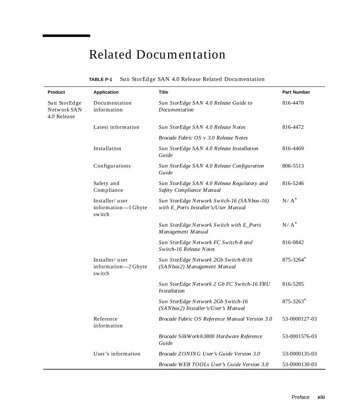
Related Documentation
TABLE P-1 Sun StorEdge SAN 4.0 Release Related Documentation
Product Application Title Part Number
Sun StorEdgeNetwork SAN4.0 Release
Documentationinformation
Sun StorEdge SAN 4.0 Release Guide toDocumentation
816-4470
Latest information Sun StorEdge SAN 4.0 Release Notes 816-4472
Brocade Fabric OS v 3.0 Release Notes
Installation Sun StorEdge SAN 4.0 Release InstallationGuide
816-4469
Configurations Sun StorEdge SAN 4.0 Release ConfigurationGuide
806-5513
Safety andCompliance
Sun StorEdge SAN 4.0 Release Regulatory andSafety Compliance Manual
816-5246
Installer/userinformation—1 Gbyteswitch
Sun StorEdge Network Switch-16 (SANbox-16)with E_Ports Installer’s/User Manual
N/A*
Sun StorEdge Network Switch with E_PortsManagement Manual
N/A*
Sun StorEdge Network FC Switch-8 andSwitch-16 Release Notes
816-0842
Installer/userinformation—2 Gbyteswitch
Sun StorEdge Network 2Gb Switch-8/16(SANbox2) Management Manual
875-3264*
Sun StorEdge Network 2 Gb FC Switch-16 FRUInstallation
816-5285
Sun StorEdge Network 2Gb Switch-16(SANbox2) Installer’s/User’s Manual
875-3263*
Referenceinformation
Brocade Fabric OS Reference Manual Version 3.0 53-0000127-03
Brocade SilkWork®3800 Hardware ReferenceGuide
53-0001576-03
User’s information Brocade ZONING User’s Guide Version 3.0 53-0000135-03
Brocade WEB TOOLs User’s Guide Version 3.0 53-0000130-03
Preface xiii
Arrays Latest information Sun StorEdge T3+ Array 2.1 Firmware ReleaseNotes
816-4771
Safety information Sun StorEdge T3+ Array Regulatory, SafetyCompliance Manual
816-4773
Documentationinformation
Sun StorEdge T3+ Array Start Here 816-4768
Installation Sun StorEdge T3 and T3+ Array SitePreparation Guide
816-0778
Sun StorEdge T3+ Array Disk Tray InstallationTask Map
816-4775
Sun StorEdge T3+ Array Installation andConfiguration Manual
816-4769
User information Sun StorEdge T3+ Array Administrator’sManual
816-4770
Host BusAdapters
Installation Sun StorEdge PCI Single Fibre Channel NetworkAdapter Installation Guide
806-7532
Sun StorEdge PCI Dual Fibre Channel HostAdapter Installation Guide
806-4199
Sun StorEdge CompactPCI Dual Fibre ChannelNetwork Adapter Installation and User’s Guide
806-6991
Sun StorEdge SBus Dual Fibre Channel HostAdapter Release Notes
816-2490
Sun StorEdge 2G FC PCI Single ChannelNetwork Adapter Installation Guide
816-4999
Sun StorEdge 2G FC PCI Double ChannelNetwork Adapter Installation Guide
816-5001
Tools Sun StorEdge TrafficManager
Sun StorEdge Traffic Manager SoftwareInstallation and Configuration Guide
816-1420
Diagnostics Storage Automated Diagnostic EnvironmentUser’s Guide, Version 2.1
816-5324
Sun Cluster Sun Cluster 3.0 Installation Guide 806-1419
Solaris VolumeManager installation
VERITAS Volume Manager 3.2 InstallationGuide
875-3165
RAID RAID Manager 6.22 User’s Guide 806-0478
StorageCabinet
Rackmountinformation
Rackmount Placement Matrix 805-4748
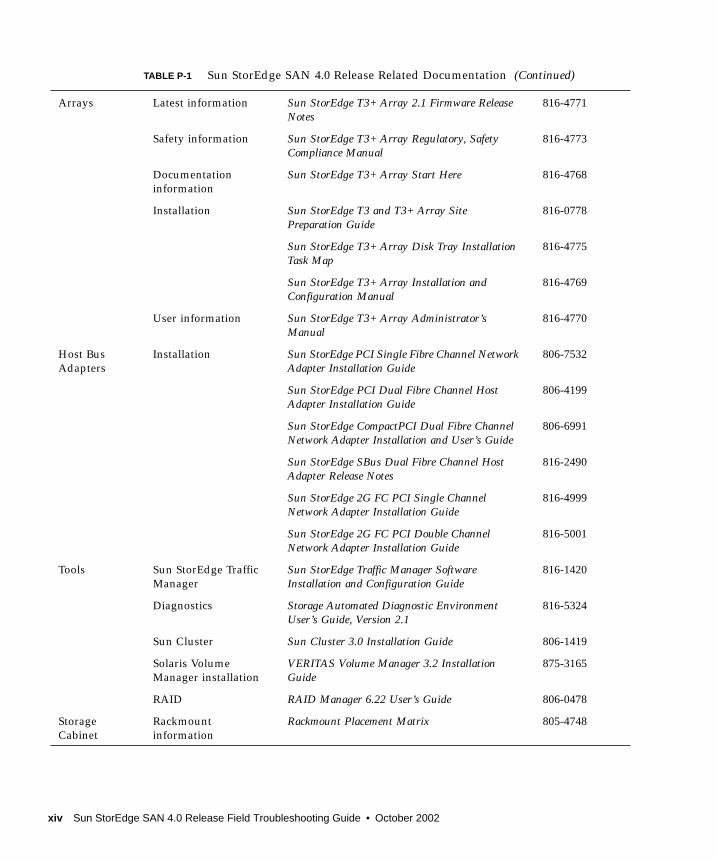
TABLE P-1 Sun StorEdge SAN 4.0 Release Related Documentation (Continued)
xiv Sun StorEdge SAN 4.0 Release Field Troubleshooting Guide • October 2002
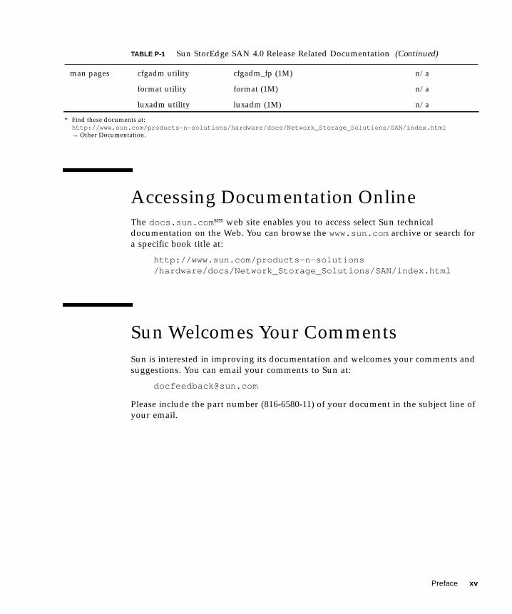
Accessing Documentation OnlineThe docs.sun.comsm web site enables you to access select Sun technicaldocumentation on the Web. You can browse the www.sun.com archive or search fora specific book title at:
http://www.sun.com/products-n-solutions/hardware/docs/Network_Storage_Solutions/SAN/index.html
Sun Welcomes Your CommentsSun is interested in improving its documentation and welcomes your comments andsuggestions. You can email your comments to Sun at:
Please include the part number (816-6580-11) of your document in the subject line ofyour email.
man pages cfgadm utility cfgadm_fp (1M) n/a
format utility format (1M) n/a
luxadm utility luxadm (1M) n/a
* Find these documents at:http://www.sun.com/products-n-solutions/hardware/docs/Network_Storage_Solutions/SAN/index.html→ Other Documentation.
TABLE P-1 Sun StorEdge SAN 4.0 Release Related Documentation (Continued)
Preface xv

xvi Sun StorEdge SAN 4.0 Release Field Troubleshooting Guide • October 2002

CHAPTER 1
Introduction
This Sun StorEdge SAN 4.0 Release Field Troubleshooting Guide provides basicprocedures for isolating problems of systems that are configured as identified in theSun StorEdge SAN 4.0 Release Configuration Guide.
The intended audience for this troubleshooting guide is Sun Service Representatives.As such, it is therefore assumed that you have been trained on all the componentsthat comprise your particular storage and switch configuration. This manual onlyaddresses troubleshooting. No repair or corrective action procedures are containedherein.
This chapter contains the following sections:
■ “Document Scope” on page 2
■ “New Features of the Sun StorEdge SAN 4.0 Release” on page 3
1

Document ScopeThe scope of this document includes the switch and interconnections (host busadapter (HBA), Small Form Factor Pluggable (SFP) 2-gigabit transceiver, and cables)on either side of the switch, as shown in the following diagram.
FIGURE 1-1 Switch and Interconnections
The Storage Automated Diagnostic Environment version 2.1 software package isrequired to support the configurations in this document.
Additional information and resources are available at:http://www.sun.com/storage/san/, or at: http://sunsolve.Sun.COM →Product Patches → PatchPro. These websites contain information on softwareversions and provide necessary patches.
Host Storage
Switch
Switch
2 Sun StorEdge SAN 4.0 Release Field Troubleshooting Guide • October 2002

New Features of the Sun StorEdge SAN4.0 ReleaseThe Sun StorEdge SAN 4.0 release supports many new features, that aresummarized in TABLE 1-1. Several features of the SAN 3.x release are not included inthe SAN 4.0 release, and many features were carried forward. For an explanation ofthe new features, see the Sun StorEdge SAN 4.0 Release Configuration Guide.
TABLE 1-1 Comparison of the SAN 3.0 and SAN 4.0 Releases
FeatureSAN 3.x Features NotSupported in SAN 4.x
SAN 3.x FeaturesIncluded In SAN 4.x SAN 4.x New Features
SupportedConfigurations
Cascadedconfigurationslimited to threelinear connectedswitches, or threeISL links betweenswitches.
N/A Cascadedconfiguration limitincreased to eightlinear connectedswitches, or sevenISL links betweenswitches. Two of theISL links can uselong-wavetransceivers andcables.
SAN configurationslimited to single-switch or simplecascades.
Support for localhost and storagedevice attachmentwith short- or long-wave cables andtransceivers fordisaster tolerantconfigurations.
SAN configurationrestrictions lifted.Meshes and otherconfigurations arenow possible.
Limit of 2 switchessupported in a SAN.
N/A Configurationssupport up to 239switches. Check withthe vendor-specificswitchdocumentation fordetails.
Limited partialfabric supported forconnections betweenhosts and switches.
N/A Full fabric supportfor connectionsbetween storagedevices, hosts andswitches.
Chapter 1 Introduction 3

Ports and Zones Configurationslimited to use ofSegmented Loop(SL) or Name Server(NS) port-basedzoning.
NS port-basedzoning supportedfor fabric capability.
WWN-based zoningsupported forinteroperabilitysupport among FC-SW2 standardcompliant switches.
N/A Overlapping port-based NS zonessupported.
WWN-based zonessupported on allswitches.
Nested port-basedzoning supported.
N/A Nested zoningsupported but notrequired.
Hard zonessupported.
N/A N/A
SL_port connectionsto arrays supported.
TL_port connectionsto the Sun StorEdgeT3 and T3+ arrayssupported for fibrechannel-arbitratedloop and fabricconfigurations.
G_ and GL_portssupported forconnections toarrays. (G_ andGL_portsautomaticallynegotiate in inter-switch connectionsto E_ports. TL_portsshould be manuallyconfigured for loopconnections tostorage devices.)
ISLs N/A Short- and long-wave cables andtransceiverssupported.
Same.
Long-wave only 1-Gbit GBICssupported forconnectivity.
N/A Long-wave andshort-wave SmallForm-factorPluggable (SFP) 2-Gbit transceiversreplace GBICs.
Long-wave only SC-SC cables supported.
Long-wave andshort-wave SCcables supported.
Long-wave andshort-wave SC-SC,SC-LC, and LC-LCcables supported.
TABLE 1-1 Comparison of the SAN 3.0 and SAN 4.0 Releases (Continued)
FeatureSAN 3.x Features NotSupported in SAN 4.x
SAN 3.x FeaturesIncluded In SAN 4.x SAN 4.x New Features
4 Sun StorEdge SAN 4.0 Release Field Troubleshooting Guide • October 2002

Supported Switches Switch hardwarelimited to Sun 1-Gbit8- and 16-portswitches.
SAN 3.0 switchescan be upgradedwith the SAN 4.0firmware. If you donot upgrade thefirmware, the 1-Gbitswitches can exist onthe same host as the2-Gbit switches, butthey can not connectto each other.
New 2-Gbit switchesintroduced.
Tools SANbox switchmanagementapplication managesthe 1-Gbit switcheswith old firmwareonly.
N/A New switchmanagement toolsare available. See thevendor-specificdocumentation fordetails.
N/A Multipathing andload balancingsupported with theSun StorEdge TrafficManagerapplication.
Multipathing andload balancingthrough the SunStorEdge TrafficManager applicationwith SunCluster 3.0or VERITAS ClusterServer.
TABLE 1-1 Comparison of the SAN 3.0 and SAN 4.0 Releases (Continued)
FeatureSAN 3.x Features NotSupported in SAN 4.x
SAN 3.x FeaturesIncluded In SAN 4.x SAN 4.x New Features
Chapter 1 Introduction 5

Host Bus Adapters(HBAs)
N/A 1-Gbit host busadapters supportedinclude:• Sun StorEdge PCI
Dual FibreChannel NetworkAdapter
• Sun StorEdge PCISingle FibreChannel NetworkAdapter,
• Sun StorEdgeCPCI Dual FibreChannel NetworkAdapter
• Sun StorEdgeSBus Dual FibreChannel NetworkAdapter
Newly supportedhost bus adaptersinclude:• Sun Sun StorEdge
2G FC PCI SingleChannel NetworkAdapter card
• Sun StorEdge 2GFC PCI DualChannel NetworkAdapter card
Supported StorageDevices
Sun StorEdge A5200and A3500FC arrayssupported.
Sun StorEdge T3 andT3+ arrayssupported.
New Sun StorEdgeT3+ array firmwareis supported. TheSun StorEdge 39x0,69x0 and 99x0 seriesare also supported.
Third-partyCompatibility
N/A N/A Interoperabilitycapability with FC-SW2 mode on thenew switches.
TABLE 1-1 Comparison of the SAN 3.0 and SAN 4.0 Releases (Continued)
FeatureSAN 3.x Features NotSupported in SAN 4.x
SAN 3.x FeaturesIncluded In SAN 4.x SAN 4.x New Features
6 Sun StorEdge SAN 4.0 Release Field Troubleshooting Guide • October 2002
Cascading Switches (E_Ports)
Note – See TABLE 2-9 on page 19 and TABLE 2-10 on page 20 for a comparison of theport nomenclature differences between Sun StorEdge and Brocade CommunicationsSystems, Inc.
In the Sun StorEdge SAN 4.0 release, switches are allowed to be cascaded togetherby using E_Ports. This cascading is allowed with either a shortwave or longwaveSmall Form Factor Pluggable (SFP) 2-gigabit transceiver. The use of shortwave SFPsallows a higher port count in a local configuration. The use of longwave SFPs andlong haul fiber optics allows users to reach geographically separated storage andservers, perhaps for disaster recovery purposes.
The following limitations exist for cascading with the Sun STorEdge SAN 4.0 release:
■ If 1- and 2-gigabit switches are used together, a maximum of 16 switches can becascaded.
■ If only 2-gigabit switches are used, a maximum of 64 switches can be cascaded.
■ The maximum distance is 10 kilometers.
■ Any number of ISL hops can be used between two switches. ISL hops do notinclude the connections between hosts and switches or between switches andstorage.
■ A maximum of 8 switches with 7 ISL links between the switches can be cascadedin a linear fashion.
Chapter 1 Introduction 7

8 Sun StorEdge SAN 4.0 Release Field Troubleshooting Guide • October 2002

CHAPTER 2
Configurations
This chapter contains information and instructions for configuring your SunStorEdge Network Fibre Channel Switch-16 with one or more hosts and storage.
This chapter contains the following sections:
■ “Supported Hardware” on page 10
■ “Supported Configurations” on page 12
■ “Operating Environments” on page 12
■ “Hosts” on page 13
■ “Storage Arrays” on page 14
■ “Host Bus Adapters” on page 15
■ “Software Packages and Patches” on page 16
■ “Switches” on page 18
■ “Switch Port Types” on page 19
■ “Zones” on page 21
■ “Configuration Guidelines” on page 22
■ “Configuration Examples” on page 24
9

Supported HardwareIn a single switch configuration, the switch is connected to the host through a fiberoptic cable to a Sun StorEdge PCI Fibre Channel Network Adapter. The other portsof the switch are connected to storage devices through a fiber optic cable.
In a cascaded configuration, two switches are connected together by way of InterSwitch Links (ISL). A name server zone can span both switches.
TABLE 2-1 Supported Hardware
Model, Part Number,or System Code Description
T3BES-RR-22-655R5
Sun StorEdge T3 and T3+ arrays
T3BWG-RR-11-327R5
3910, 3960 Sun StorEdge 39x0 storage series
6910, 6960 Sun StorEdge 69x0 storage series
9910, 9960 Sun StorEdge 99x0 storage series
X6799A Sun StorEdge PCI Single Fibre Channel Network Adapter
X6727A Sun StorEdge PCI Dual Fibre Channel Network Adapter+
X6748A Sun StorEdge cPCI Dual Fibre Channel Network Adapter
X6757A Sun StorEdge SBus Dual Fibre Channel Host Bus Adapter
X6767A Sun StorEdge 2G FC PCI Single Channel Network Adapter
X6768A Sun StorEdge 2G FC PCI Dual Channel Network Adapter
XSFP-SW-2Gb Short-wave SFP (up to 300 meters)
XSFP-LW-2Gb Long-wave SFP (up to 10 km with no modifications to theswitch or up to 40 km with modifications to the switch portbuffer credits)1
X973A 2-meter fiber-optic cable (SC-SC)
X9715A 5-meter fiber-optic cable (SC-SC)
X978A 15-meter fiber-optic cable (SC-SC)
X9720A SC-SC cable coupler
10 Sun StorEdge SAN 4.0 Release Field Troubleshooting Guide • October 2002
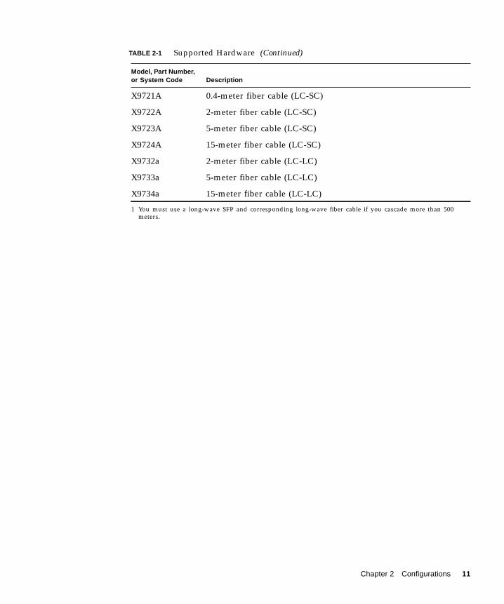
X9721A 0.4-meter fiber cable (LC-SC)
X9722A 2-meter fiber cable (LC-SC)
X9723A 5-meter fiber cable (LC-SC)
X9724A 15-meter fiber cable (LC-SC)
X9732a 2-meter fiber cable (LC-LC)
X9733a 5-meter fiber cable (LC-LC)
X9734a 15-meter fiber cable (LC-LC)
1 You must use a long-wave SFP and corresponding long-wave fiber cable if you cascade more than 500meters.
TABLE 2-1 Supported Hardware (Continued)
Model, Part Number,or System Code Description
Chapter 2 Configurations 11

Supported ConfigurationsTo support a high-availability environment, use these configurations to ensureswitch redundancy. See the example diagrams in this chapter for more informationon the supported configurations.
Operating Environments
TABLE 2-2 Sun StorEdge SAN 4.0 Release Sun Operating Environment CompatibilityMatrix
Operating Environment Version Notes
Sun Solaris 2.6 Not supported
Sun Solaris 7 Not supported
Sun Solaris 8 02/02 (Update 7) or later
Sun Solaris 9
12 Sun StorEdge SAN 4.0 Release Field Troubleshooting Guide • October 2002
Hosts
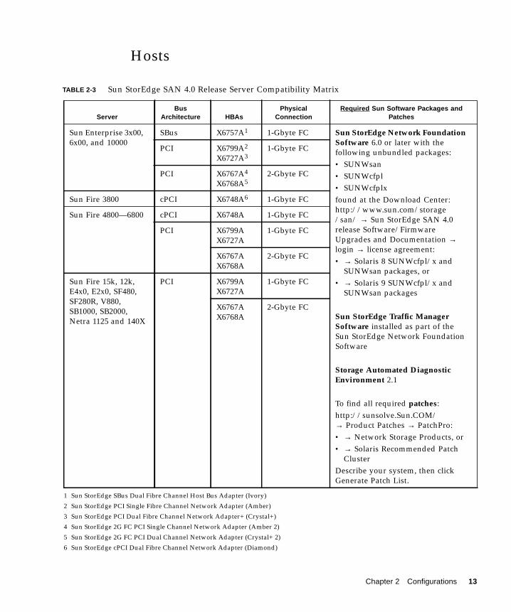
TABLE 2-3 Sun StorEdge SAN 4.0 Release Server Compatibility Matrix
ServerBus
Architecture HBAsPhysical
ConnectionRequired Sun Software Packages and
Patches
Sun Enterprise 3x00,6x00, and 10000
SBus X6757A1
1 Sun StorEdge SBus Dual Fibre Channel Host Bus Adapter (Ivory)
1-Gbyte FC Sun StorEdge Network FoundationSoftware 6.0 or later with thefollowing unbundled packages:• SUNWsan• SUNWcfpl• SUNWcfplxfound at the Download Center:http://www.sun.com/storage/san/ → Sun StorEdge SAN 4.0release Software/FirmwareUpgrades and Documentation →login → license agreement:• → Solaris 8 SUNWcfpl/x and
SUNWsan packages, or• → Solaris 9 SUNWcfpl/x and
SUNWsan packages
Sun StorEdge Traffic ManagerSoftware installed as part of theSun StorEdge Network FoundationSoftware
Storage Automated DiagnosticEnvironment 2.1
To find all required patches:http://sunsolve.Sun.COM/→ Product Patches → PatchPro:• → Network Storage Products, or• → Solaris Recommended Patch
ClusterDescribe your system, then clickGenerate Patch List.
PCI X6799A2
X6727A3
2 Sun StorEdge PCI Single Fibre Channel Network Adapter (Amber)
3 Sun StorEdge PCI Dual Fibre Channel Network Adapter+ (Crystal+)
1-Gbyte FC
PCI X6767A4
X6768A5
4 Sun StorEdge 2G FC PCI Single Channel Network Adapter (Amber 2)
5 Sun StorEdge 2G FC PCI Dual Channel Network Adapter (Crystal+ 2)
2-Gbyte FC
Sun Fire 3800 cPCI X6748A6
6 Sun StorEdge cPCI Dual Fibre Channel Network Adapter (Diamond)
1-Gbyte FC
Sun Fire 4800—6800 cPCI X6748A 1-Gbyte FC
PCI X6799AX6727A
1-Gbyte FC
X6767AX6768A
2-Gbyte FC
Sun Fire 15k, 12k,E4x0, E2x0, SF480,SF280R, V880,SB1000, SB2000,Netra 1125 and 140X
PCI X6799AX6727A
1-Gbyte FC
X6767AX6768A
2-Gbyte FC
Chapter 2 Configurations 13

Host/Operating Environment Rules■ All hosts in a zone must be running Solaris 8 Release 4/01 operating environment
with all appropriate patches installed.
■ Mixing PCI Dual Fibre Channel Network Adapter and PCI single Fibre ChannelNetwork Adapter HBAs in the same switch zone is supported.
■ Mixing an Sbus host (with a PCI card) and PCI hosts within the same zone issupported. You must be using PCI dual Fibre Channel Network Adapter and PCIsingle Fibre Channel Network Adapter HBAs.
Storage Arrays
TABLE 2-4 Sun StorEdge SAN 4.0 Release Storage Array Compatibility Matrix
Firmware Levels for Storage Version Notes
Sun StorEdge T3 array 1.17b and 1.18 controllerfirmware
Translated loop (TL) switch mode
Sun StorEdge T3+ array 2.1 controller firmware TL/fabric switch mode
Sun StorEdge 39x0 array 2.0 and 2.1 TL/fabric switch mode
Sun StorEdge 69x0 array Requires switch hardware or firmwareupgrade to use SAN 4.0 capabilities.
Sun StorEdge 9960 & 9910 arrays
Sun StorEdge 9980 & 9970 arrays
14 Sun StorEdge SAN 4.0 Release Field Troubleshooting Guide • October 2002

Array Storage Rules
The following tables specify the supported features of the Sun StorEdge T3 array.
Host Bus Adapters
TABLE 2-5 Supported Features of the Sun StorEdge T3 Array
Feature Supported
Cascading Yes
Zone Type Name Server zone1
1 The host must be connected to the F_Port on the switch; a Sun StorEdge T3 array must be connected to the TLport of the switch.
Maximum number of arrays per SL zone 8
Maximum initiators per LUN 2
Maximum initiators per zone 22
2 This implies 2 initiators (2 hosts) for simple arrays (T3WG), but 4 initiators (2 hosts) for a partner pair (T3ES).Each host has one path to each of the Sun StorEdge T3 arrays in the partner pair.
TABLE 2-6 Sun StorEdge SAN 4.0 Release HBA Compatibility Matrix
FW-Code Levels for HBAs and I/O Boards Version
X6757A, Sun StorEdge SBus Dual Fibre Channel Host Bus Adapter 1.13.06 or higher
X6799A, Sun StorEdge PCI Single Fibre Channel Network Adapter 1.13 or higher
X6727A, Sun StorEdge PCI Dual Fibre Channel Network Adapter+ 1.13 or higher
X6767A, Sun StorEdge 2G FC PCI Single Channel Network Adapter 1.13.08 or higher
X6768A, Sun StorEdge 2G FC PCI Dual Channel Network Adapter 1.13.08 or higher
X6748A, Sun StorEdge cPCI Dual Fibre Channel Network Adapter 1.13 or higher
Chapter 2 Configurations 15

Software Packages and PatchesYou can download software packages or patches with the following procedures.
▼ To generate the most recent patch list for a Sun SolarisRelease
1. Access the SunSolve web site.
http://sunsolve.Sun.COM/
The SUNSOLVE ONLINE menu is displayed.
2. Under SunSolve Contents, click Product Patches.
3. Under Patch Analysis Tools, click PatchPro.
4. Click Solaris Recommended Patch Cluster.
The PATCHPRO Interactive menu is displayed.
5. Select all the appropriate features of your system in the following areas of themenu:
■ Operating System Release
■ Platform
6. Click Generate Patch List.
▼ To generate the most recent patch list for a specific SunStorEdge SAN 4.0 Release Configuration
1. Access the SunSolve web site.
http://sunsolve.Sun.COM/
The SUNSOLVE ONLINE menu is displayed.
2. Under SunSolve Contents, click Product Patches.
3. Under Patch Analysis Tools, click PatchPro.
4. Click Network Storage Products.
The PATCHPRO Interactive menu is displayed.
5. Select all the appropriate features of your system in the following areas of themenu:
■ OS Release■ Platform■ Disk Array■ Tape Libraries
16 Sun StorEdge SAN 4.0 Release Field Troubleshooting Guide • October 2002

■ Disk Drives■ Tape Drives■ Switches and HBAs■ SAN Products | Brocade SAN Release■ Software
6. Click Generate Patch List.
Unbundled Software
For a list of unbundled software, refer to TABLE 2-7.
Note – The packages and/or patches listed in TABLE 2-7 may not be present in allconfigurations.
TABLE 2-7 Unbundled Software
Package Minimum Revision Minimum Patch (if any)
JAVA SDK/JDK 1.3.02
StorageTek 9840 1.28.126
Instant Image 3.0
SNDR 3.0
Alternate Pathing 2.3.1 110722-01110432-04
Sun Enterprise3x00/4x00/5x00/6x00 FlashProm
3.2.28 103346-29
Sun Fire3800/4800/4810/6800 FlashProm
5.11.6 111346-02
E450 Flash Prom 3.22.0 106122-09
E250 Flash Prom 3.22.0 106530-06
E420R Flash Prom 3.29.0 109082-04
Chapter 2 Configurations 17

SwitchesFor high availability, configure the Sun StorEdge Network FC Switch-16 switch inparallel.
TABLE 2-8 Sun StorEdge SAN 4.0 Release Optional Software Packages Compatibility Matrix
Optional Software Packages Version/upgrade Notes
Sun Cluster 3.0 Update 2
VERITAS Cluster Support 3.4
VERITAS File System 3.4
VERITAS Volume Manager (VxVM)Support (includes VERITAS DMP)
3.2
Solstice DiskSuite 4.2.1 See SunSolve for the latest patches.
StorTools 4.2 Extra functionality for V880
Storage Automated DiagnosticEnvironment
2.1 See SunSolve for the latest patches.
Sun StorEdge Network Storage Agent 2.1 See SunSolve for the latest patches.
Sun StorEdge Network Data Replicator 3.0 See SunSolve for the latest patches.
Sun StorEdge Component Manager 2.2 See SunSolve for the latest patches.
VERITAS NetBAckup 3.4
Solstice Backup 6.0b See SunSolve for the latest patches.
Sun StorEdge Instant Image 3.0 See SunSolve for the latest patches.
“On Demand Node Creation” SUNWcfpl:VERSION=11.8.0,REV=2001.07.14.21.42,SUNWcfplx:VERSION=11.8.0,REV=2001.07.14.21.42
18 Sun StorEdge SAN 4.0 Release Field Troubleshooting Guide • October 2002
Switch Port Types
New Sun StorEdge SAN 4.0 Release Port Types
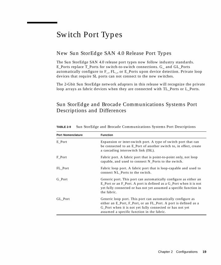
The Sun StorEdge SAN 4.0 release port types now follow industry standards.E_Ports replace T_Ports for switch-to-switch connections. G_ and GL_Portsautomatically configure to F_, FL_, or E_Ports upon device detection. Private loopdevices that require SL ports can not connect to the new switches.
The 2-Gbit Sun StorEdge network adapters in this release will recognize the privateloop arrays as fabric devices when they are connected with TL_Ports or L_Ports.
Sun StorEdge and Brocade Communications Systems PortDescriptions and Differences
TABLE 2-9 Sun StorEdge and Brocade Communications Systems Port Descriptions
Port Nomenclature Function
E_Port Expansion or inter-switch port. A type of switch port that canbe connected to an E_Port of another switch to, in effect, createa cascading interswitch link (ISL).
F_Port Fabric port. A fabric port that is point-to-point only, not loopcapable, and used to connect N_Ports to the switch.
FL_Port Fabric loop port. A fabric port that is loop-capable and used toconnect NL_Ports to the switch.
G_Port Generic port. This port can automatically configure as either anE_Port or an F_Port. A port is defined as a G_Port when it is notyet fully connected or has not yet assumed a specific function inthe fabric.
GL_Port Generic loop port. This port can automatically configure aseither an E_Port, F_Port, or an FL_Port. A port is defined as aG_Port when it is not yet fully connected or has not yetassumed a specific function in the fabric.
Chapter 2 Configurations 19
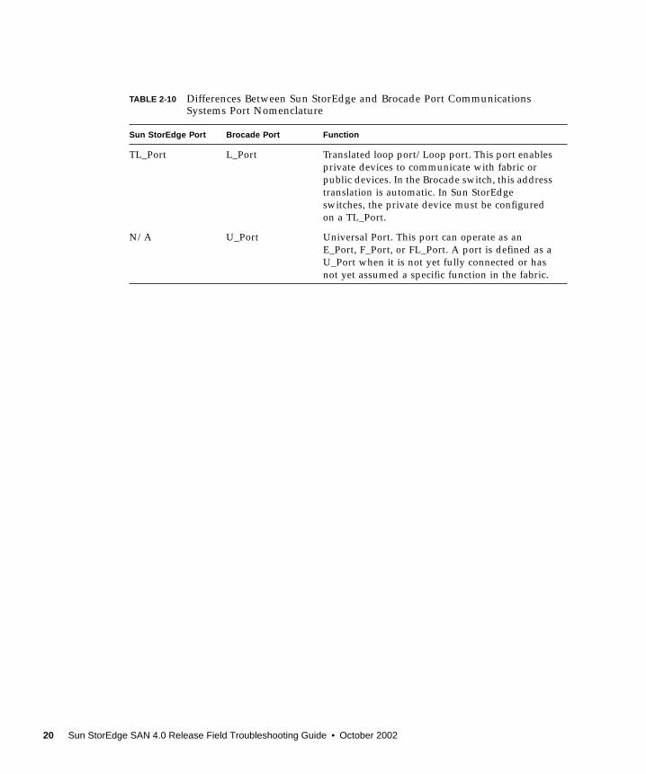
TABLE 2-10 Differences Between Sun StorEdge and Brocade Port CommunicationsSystems Port Nomenclature
Sun StorEdge Port Brocade Port Function
TL_Port L_Port Translated loop port/Loop port. This port enablesprivate devices to communicate with fabric orpublic devices. In the Brocade switch, this addresstranslation is automatic. In Sun StorEdgeswitches, the private device must be configuredon a TL_Port.
N/A U_Port Universal Port. This port can operate as anE_Port, F_Port, or FL_Port. A port is defined as aU_Port when it is not yet fully connected or hasnot yet assumed a specific function in the fabric.
20 Sun StorEdge SAN 4.0 Release Field Troubleshooting Guide • October 2002

ZonesZoning allows the user to divide the switch ports into zones for more efficient andsecure communication among functionally grouped nodes. There are several typesof zones and a port may be defined in any. No port can be in all zone typessimultaneously.
Name Server Zones
Name server zones allow the division of the fabric (one or more Switch chassis) intoas many as 256 fabric-wide zones; each name server zone defines which ports ordevices receive name server information, as defined by the FC-GS3 document.
Overlapping Zones
The new Sun StorEdge SAN 4.0 release now supports WWN-based zones, as well asport-based zones. Port-based and WWN-based zones can overlap. When creatingoverlapping NS zones, one or more switch ports is in at least two zones. When aport is in multiple zones, one host or storage device attached to a switch port to be amember of many zones and resources can be shared. If a resource is shared inmultiple zones, it can be made available to multiple zones by using overlappingzones.
When connecting multiple switches, zones can help manage the complexity ofsharing resources. For example, you can use port zoning to make all the disks of aSun StorEdge T3 array belong to the same zone in a SAN. Alternately, you can sharethe resources of the array among several NS zones.
Refer to vendor-specific switch documentation to determine the maximum numberof zones you can have in a configuration.
Zone nesting, where zones exist inside other zones, is also possible.
Chapter 2 Configurations 21
Zoning Rules■ A minimum of one switch port per zone
■ A maximum of 16 zones per 16-port switch
■ A maximum of 30 zones for cascading 16-port to 16-port switches
■ Port-based and world-wide name (WWN)-based zoning is supported.
■ Server and storage may be in the same name server zone across ISLs on separateswitches. This enables you to have servers at a recovery site. It also means youcan have local and remote storage in the same zone, so that storage can bemirrored at both locations.
Configuration Guidelines
SwitchesFor high-availability applications, configure two sets of switches in parallel.
Zones and Arrays■ Sun StorEdge T3 arrays support name server zones (or zones in which a host has
made a point-to-point Fabric connection to a switch and the Sun StorEdge T3array is attached to a TL port).
■ Do not mix different arrays in the same zone. A single zone can contain only SunStorEdge 3900 arrays, or only Sun StorEdge T3 arrays.
■ You may configure a minimum of one port per zoneFor example, a 16-port switch can have a maximum of 16 zones.
22 Sun StorEdge SAN 4.0 Release Field Troubleshooting Guide • October 2002

Zones and StorageYou can dynamically add storage to a port-based or WWN-based zone, usingcfgadm procedures for the Sun StorEdge T3 arrays. This requires the Sun StorEdgeT3 and T3+ arrays to be connected as TL or Fabric devices.
Cascading Rules■ Hub-to-switch connectivity is not supported
■ If 1- and 2-gigabit switches are used together, a maximum of 16 switches can becascaded.
■ If only 2-gigabit switches are used, a maximum of 64 switches can be cascaded.
■ The maximum distance is 10 kilometers.
■ Any number of ISL hops can be used between two switches.
■ ISL hops do not include the connections between hosts and switches or betweenswitches and storage.
Rules for Adding and Removing Devices Whilethe Hosts are OnlineYou can add all initial and additional storage devices while the host is online.
In high availability configurations, where alternative methods to reconstruct the dataexist, you can remove a device or path. Host volume management or multi-pathingsoftware handles this device removal. For non-available configurations, you mustensure that no host application is configured to use the device.
In the case of a fabric configuration (name server zone), you must unconfigure thedevice on the host. This ensures that during the boot process the host does notattempt to probe this device to create device nodes.
You can add or remove a host without shutting down the SAN.
TABLE 2-11 Arrays, Zones, and Initiators
Array Maximum Arrays/Zone Maximum Initiators/Zone
Sun StorEdge T3array
252 (252 Sun StorEdge T3 arrays in a workgroup, or 126 Sun StorEdge T3 arrays in anenterprise configuration)
252
Chapter 2 Configurations 23

Configuration Examples
Single Host Connected to One Storage ArrayFIGURE 2-1 shows one host connected through fiber-optic cables to a Sun StorEdge T3array enterprise configuration.
FIGURE 2-1 Single Host Connected to One Sun StorEdge T3 Array EnterpriseConfiguration
Host
Host Adapter
Host Adapter
Switches
Sun StorEdge T3 array partner pair
Fibre-optic cables
24 Sun StorEdge SAN 4.0 Release Field Troubleshooting Guide • October 2002
Single Host Connected to Multiple Storage ArraysFIGURE 2-2 shows a single host connected to multiple Sun StorEdge T3 array partnerpairs.
Note – You can attach different types of storage devices to the same switch, as longas the storage devices are on different zones.
Each controller that is connected to a switch must have a unique loop ID. Wheneveryou add a second controller to a switch, make sure that the loop ID of the controllerbeing connected is different from the loop ID of any other controller currentlyconnected to the same switch.
Caution – Make sure that the controller module of the array is split between twoswitches. For example, connect controller A to switch 1 and controller B to switch 2.
Chapter 2 Configurations 25
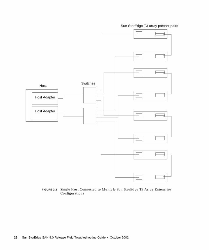
FIGURE 2-2 Single Host Connected to Multiple Sun StorEdge T3 Array EnterpriseConfigurations
Sun StorEdge T3 array partner pairs
HostSwitches
Host Adapter
Host Adapter
26 Sun StorEdge SAN 4.0 Release Field Troubleshooting Guide • October 2002

MultihostFIGURE 2-3 shows two hosts connected to four Sun StorEdge T3 array partner pairs.
FIGURE 2-4 shows two hosts connected to a Sun StorEdge T3 array Partner Group inwhich each host maintains separate, non-shared storage.
Note – You can attach different storage types to the same switch so long as thestorage devices are on different zones.
Each controller that is connected to a switch must have a unique loop ID. Wheneveryou add a second controller to a switch, make sure that the loop ID of the controllerbeing connected is different from the loop ID of any other controller currentlyconnected to the same switch.
Caution – Ensure that the controller modules are not connected to the same switch.
Chapter 2 Configurations 27

FIGURE 2-3 Two Hosts Connected to Four Sun StorEdge T3 Array EnterpriseConfigurations
Sun StorEdge T3 partner pairs
SwitchesHost
Host
Host Adapter
Host Adapter
Host Adapter
Host Adapter
28 Sun StorEdge SAN 4.0 Release Field Troubleshooting Guide • October 2002
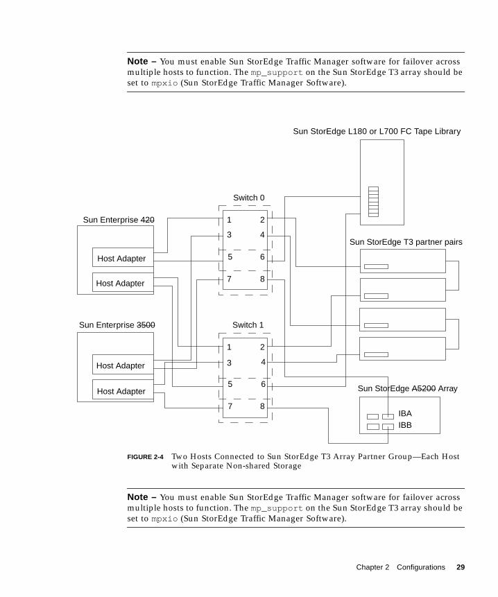
Note – You must enable Sun StorEdge Traffic Manager software for failover acrossmultiple hosts to function. The mp_support on the Sun StorEdge T3 array should beset to mpxio (Sun StorEdge Traffic Manager Software).
FIGURE 2-4 Two Hosts Connected to Sun StorEdge T3 Array Partner Group—Each Hostwith Separate Non-shared Storage
Note – You must enable Sun StorEdge Traffic Manager software for failover acrossmultiple hosts to function. The mp_support on the Sun StorEdge T3 array should beset to mpxio (Sun StorEdge Traffic Manager Software).
Sun StorEdge L180 or L700 FC Tape Library
Sun StorEdge T3 partner pairs
Sun StorEdge A5200 Array
Switch 0
Switch 1
Sun Enterprise 420
Sun Enterprise 3500
Host Adapter
Host Adapter
Host Adapter
Host Adapter
IBAIBB
1
3
5
7
2
4
6
8
1
3
5
7
2
4
6
8
Chapter 2 Configurations 29

30 Sun StorEdge SAN 4.0 Release Field Troubleshooting Guide • October 2002

CHAPTER 3
Diagnostics
This chapter provides an overview of the tools you can use to monitor, diagnose,troubleshoot, and gather information on the Sun StorEdge SAN 4.0 Release and onthe Sun StorEdge Network Fibre Channel Switch-16. Detailed installation andconfiguration information can be found in the respective documentation of the tools.
This chapter contains the following sections:
■ “Diagnostic Tools” on page 32
■ “Storage Automated Diagnostic Environment Version 2.1” on page 32
■ “Sun Explorer Data Collector (SUNWexplo) and T3Extractor” on page 40
■ “Diagnosing and Troubleshooting the Sun Switch” on page 41
31

Diagnostic Tools
Storage Automated Diagnostic EnvironmentVersion 2.1The Storage Automated Diagnostic Environment version 2.1 is a host-based onlinehealth and diagnostic monitoring tool for a storage area network (SAN) and direct-attached storage (DAS) devices. It can be configured to monitor on a 24-hour basis,collecting information that enhances the reliability, availability, and serviceability(RAS) of the storage devices.
FIGURE 3-1 Storage Automated Diagnostic Environment Version 2.1 Home Window
32 Sun StorEdge SAN 4.0 Release Field Troubleshooting Guide • October 2002
The Storage Automated Diagnostic Environment version 2.1 offers the followingfeatures:
■ A common web-based user interface for device monitoring and diagnostics
■ Distributed test invocation by means of lists or topology. You can run the teststhrough the Storage Automated Diagnostic Environment GUI or through thecommand line interface (CLI).
■ Topology grouping for multi-level hosts and components
■ Alternate master support for redundancy
■ Revision checking
■ Support for the Storage Service Processor and virtualization engine componentsof Sun StorEdge 3900 and 6900 series offerings
■ Remote notification through SRS, SRS/NetConnect, Sun StorEdge RemoteResponse (SSRR), HTTP, and SNMP Providers, or email
■ Support for direct attached storage (DAS) and storage area networks (SANs)
Storage Automated Diagnostic Environment Version 2.1Functions
For each device, the Storage Automated Diagnostic Environment version 2.1performs the following functions:
1. Sends the information, by way of a discovery event, to the system administratorthrough an interface with the transport mechanisms.
Note – The first access to a device yields a discovery event that collects all theinformation about that device, plus other events for other preconfigured devices,that may be generated by health monitors.
2. Reads the proper /var/adm/messages files, finds relevant entries, and reportsthem as events through the local email notification mechanism, if configured.
3. Connects to Sun StorEdge T3 and T3+ array storage devices directly through in-band data paths and out-of-band management paths.
4. Reads the device’s configuration and state information, stores it locally in thecache, compares the results of the last run, and transmits the differences.
5. Reads threshold information and reports errors when the frequency thresholdreaches predefined levels.
Chapter 3 Diagnostics 33

Storage Automated Diagnostic Environment Version 2.1 AgentFunctionality
The Storage Automated Diagnostic Environment version 2.1 remotely monitors Sunnetwork storage devices. The Storage Automated Diagnostic Environment canmonitor host message files for errors, or connect directly through the “in-band” datapath or “out-of-band” management path of Sun StorEdge devices, in order to obtainstatus information about each device being monitored.
Storage Automated Diagnostic Environment Version 2.1 DiagnosticFunctionality
Diagnostic tests have been integrated into the Storage Automated DiagnosticEnvironment for device diagnostics and field replaceable unit (FRU) isolation. Eachtest can be run individually from the command line interface (CLI) or from theStorage Automated Diagnostic Environment GUI.
The following tests are described in the Storage Automated Diagnostic EnvironmentUser’s Guide, Version 2.1.
■ Sun StorEdge PCI FC-100 Host Adapter Board Test (ifptest)■ Sun StorEdge PCI Dual Fibre Channel Host Adapter Board Test (qlctest)■ Sun StorEdge SBus FC-100 Host Adapter Board Test (socaltest)■ Sun StorEdge Network FC Switch-16 Switch Test (switchtest)■ Sun StorEdge T3 and T3+ array Tests (t3ofdg, t3test, t3volverify)■ Virtualization Engine Tests (vediag, veluntest)■ Brocade Silkworm Test (brocadetest)
From the Storage Automated Diagnostic Environment GUI, you can select tests fromthe topology or from a list view. When the tests execute, the Storage AutomatedDiagnostic Environment initiates the test on the proper host. You can retrieve testresults by using the Test Manager selection from the GUI.
Running Diagnostic Tests From the GUI
If you run the diagnostic test from the Storage Automated Diagnostic Environmenthome window, you can easily access test configuration, control, and results using thebuttons in the dialog boxes. The test parameter options, however, are unique foreach test and are illustrated in the individual sections with each test in this chapter.
34 Sun StorEdge SAN 4.0 Release Field Troubleshooting Guide • October 2002
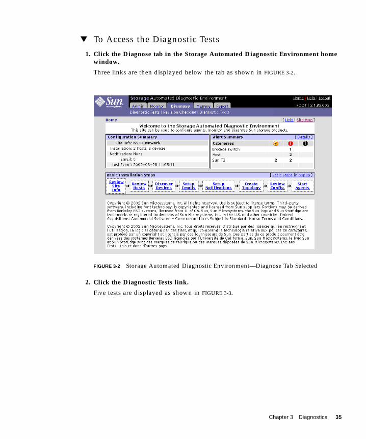
▼ To Access the Diagnostic Tests
1. Click the Diagnose tab in the Storage Automated Diagnostic Environment homewindow.
Three links are then displayed below the tab as shown in FIGURE 3-2.
FIGURE 3-2 Storage Automated Diagnostic Environment—Diagnose Tab Selected
2. Click the Diagnostic Tests link.
Five tests are displayed as shown in FIGURE 3-3.
Chapter 3 Diagnostics 35

FIGURE 3-3 Storage Automated Diagnostic Environment—Diagnostic Tests Window
You can run Storage Automated Diagnostic Environment diagnostic tests from the“Test from Topo” or from the Test from List links. FIGURE 3-4, FIGURE 3-5, andFIGURE 3-6 show an example of selecting and modifying the Test from Topo link. Thefunctional tests are designed to test the target FRU and operate on in-band or out-of-band data paths. The Storage Automated Diagnostic Environment causes the test tobe run on the appropriate Host.
Storage Automated Diagnostic Environment’s implementation of diagnostic testsverify the operation of all the user-selected components. Tests are selected from agraphical view of the system’s topology. The Storage Automated DiagnosticEnvironment version 2.1 Graph view shows the physical topology of a system ormerged system. Using the Topology view, you can select specific subtests and testoptions. The monitoring status of devices and links appears both in the test topologyview and in the list view.
36 Sun StorEdge SAN 4.0 Release Field Troubleshooting Guide • October 2002
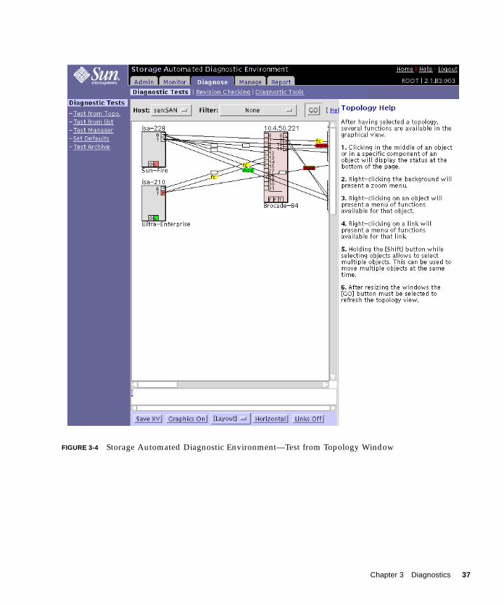
FIGURE 3-4 Storage Automated Diagnostic Environment—Test from Topology Window
Chapter 3 Diagnostics 37
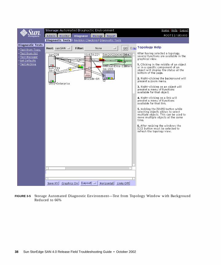
FIGURE 3-5 Storage Automated Diagnostic Environment—Test from Topology Window with BackgroundReduced to 66%
38 Sun StorEdge SAN 4.0 Release Field Troubleshooting Guide • October 2002

FIGURE 3-6 Storage Automated Diagnostic Environment—Test from Topology Window with BackgroundReduced to 66% and Components Arranged for Viewing
Chapter 3 Diagnostics 39

Sun Explorer Data Collector (SUNWexplo) andT3ExtractorBoth the Sun Explorer Data Collector and the T3Extractor are essential datagathering tools that are required for service calls or escalations. Both are command-line, host-based tools that collect pertinent information you need to see the completepicture of the host.
Visit the following websites for more information and to download these tools.
Explorer
http://eservices.central/knowledge/products/explorer/
T3Extractor
http://hes.west/nws/products/T3/tools.html
Note – You can gather the same information by querying the Storage AutomatedDiagnostic Environment version 2.1 that you can gather using the sanbox API. Thesemethods are completely supported, unlike command-line sanbox API usage.
40 Sun StorEdge SAN 4.0 Release Field Troubleshooting Guide • October 2002

Diagnosing and Troubleshooting the SunSwitchFor procedures for diagnosing and troubleshooting the Sun StorEdge Network FibreChannel Switch-16, see the Sun StorEdge Network 2Gb Switch-16 (SANbox2)Installer’s/User’s Manual. This manual can be found with the following steps.
1. Access the SAN Solutions web site.
http://www.sun.com/products-n-solutions/hardware/docs/Network_Storage_Solutions/SAN/index.html
The SAN Solutions menu is displayed.
2. Click Other Documentation.
3. Click Sun StorEdge[tm] Network 2Gb Switch-16 (SANbox2) Installer’s/User’sManual.
See Section 4, Diagnostics/Troubleshooting.
Using Switch Counter InformationSwitch counter information can be helpful in supporting troubleshooting the SunStorEdge Network Fibre Channel Switch-16. Some general points to keep in mindwhen viewing switch counter information are:
■ Quickly increasing counter values or abnormally high counter values mayindicate a problem.
■ A LIP that occurs on one port in a zone propagates to all the ports that havedevices attached to them in the same zone. The LIP counter is incremented on allthose ports.
■ Normal activity can also increase counter values.
■ Counters increment on power cycles.
Note – Switch Counter data should only be used as supporting data for diagnostics.Do not use switch counter information as the primary source in the troubleshootingprocess.
Chapter 3 Diagnostics 41
Sun StorEdge Network Fibre Channel Switch-16 counter information can be calledup by using the SANbox Manager application. See the Sun StorEdge Network 2GbSwitch-16 (SANbox2) Management Manual. This manual can be found with thefollowing steps.
1. Access the SAN Solutions web site.
http://www.sun.com/products-n-solutions/hardware/docs/Network_Storage_Solutions/SAN/index.html
The SAN Solutions menu is displayed.
2. Click Other Documentation.
3. Click Sun StorEdge[tm] Network 2Gb Switch-16 (SANbox2) Management Manual.
See Section 4, Managing Ports.
qlctest Test
If you are running the Storage Automated Diagnostic Environment version 2.1application, you can also run the Sun StorEdge PCI Dual Fibre Channel HostAdapter Board Test (qlctest) which might increase the following counters if thetest is run while the HBA is connected to the switch:
■ In frames
■ Out frames
■ Link failure
■ Sync losses 100ms
■ Invalid tx words rec
■ LIP total received
■ LIP F7F7
■ LIP F8F7
■ AL Init Attempts
■ Sync Loss
■ LIP during Init
42 Sun StorEdge SAN 4.0 Release Field Troubleshooting Guide • October 2002

CHAPTER 4
Troubleshooting Example
In this section, a troubleshooting example is shown with a SAN 4.0 configured withSun StorEdge 2 Gbyte FC switches and two Sun StorEdge T3+ arrays in anenterprise configuration.
This chapter contains the following sections:
■ “Example Configuration” on page 44
■ “Example Assumptions” on page 45
■ “Troubleshooting Outline” on page 45
■ “Troubleshooting Example of a Host–to–Switch Error” on page 47
■ “Determine the Error” on page 47
■ “Determine the Extent of the Problem” on page 53
■ “Check the Array Status” on page 55
■ “Check the Switch Status” on page 56
■ “Test the FRUs” on page 57
■ “Verify the Fix” on page 61
43

Example ConfigurationThe troubleshooting example has the following configuration:
■ One Enterprise 450 Workgroup Server
■ Solaris 9 update 1 with all relevant Sun StorEdge SAN 4.0 Release patches andpackages
■ Two Sun StorEdge T3+ arrays in an enterprise configuration (1 LUN per array)
■ Two Sun StorEdge 2-Gbyte Fibre Channel switches
■ One single-port 2-Gbyte HBA and one dual-port 2-Gbyte HBA
■ Storage Automated Diagnostic Environment version 2.1 with patch 113230-01
The setup example high-level topology is displayed in FIGURE 4-1.
FIGURE 4-1 Troubleshooting Example Viewed with Storage Automated Diagnostic Environment Version 2.1
44 Sun StorEdge SAN 4.0 Release Field Troubleshooting Guide • October 2002

Example AssumptionsThe troubleshooting example has the following assumptions:
■ The latest patches, firmware, and packages are installed and running
■ No host-based volume management software installed
■ The two switches are zoned such that they present two isolated paths from theHBAs through the ISL links to the Sun StorEdge T3+ arrays
■ Each HBA has physical connectivity to only one Sun StorEdge T3+ arrays
■ The Storage Automated Diagnostic Environment version 2.1 is configured toautomatically send email alert messages to the root user email account
Troubleshooting OutlineThis section lists the broad steps on how to approach a SAN problem. It lays out amethodical approach and lists various tools and resources available at each step.Using the Storage Automated Diagnostic Environment version 2.1 for monitoringvastly decreases the time-consuming process of narrowing down the problem.
1. Determine the error.
■ Storage Automated Diagnostic Environment version 2.1 alert/email
■ /var/adm/messages
■ Application-specific errors
2. Determine the extent of the problem.
■ Storage Automated Diagnostic Environment version 2.1 topology or devicemonitoring view
■ cfgadm -al command output
■ luxadm -e port command output
■ Multipathing information
Note – The information gathered at this point determines the subsection to focusattention on: Host-to-Switch, Switch-to-Switch (cascaded), or Switch-to-Storage.
Chapter 4 Troubleshooting Example 45

3. Check the array status.
■ luxadm display command output
■ LED status
■ Output from telnet session to the Sun StorEdge T3+ array
■ Explorer/Sun StorEdge T3+ array Extractor output
4. Check the Sun StorEdge 2 Gb FC switch status.
■ Storage Automated Diagnostic Environment version 2.1 device monitoring view
■ SANbox2 Switch GUI display
■ LED status on the Sun StorEdge 2 Gb FC switch
Note – You can use the Storage Automated Diagnostic Environment version 2.1 todetect user configuration errors that may not show up as hard errors anywhere else.For example, a user might accidentally change a switch port to a different mode (TLto F), or rezone a switch.
5. Test the FRUs.
■ Storage Automated Diagnostic Environment version 2.1 diagnostic tests(switchtest and qlctest)
■ Sun StorEdge T3+ array tests (OFDG)
6. Verify the fix.
■ Storage Automated Diagnostic Environment version 2.1 monitoring status
■ Storage Automated Diagnostic Environment version 2.1 diagnostic tests
■ /var/adm/messages log information
■ Multipathing status returns to normal condition
■ LED status
46 Sun StorEdge SAN 4.0 Release Field Troubleshooting Guide • October 2002

Troubleshooting Example of aHost–to–Switch Error
Determine the ErrorThe first indication of a problem can come from a Storage Automated DiagnosticEnvironment version 2.1 email alert:
Chapter 4 Troubleshooting Example 47
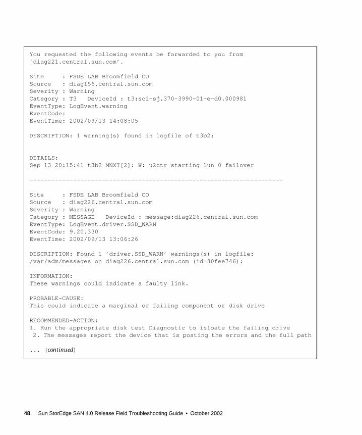
You requested the following events be forwarded to you from’diag221.central.sun.com’.
Site : FSDE LAB Broomfield COSource : diag156.central.sun.comSeverity : WarningCategory : T3 DeviceId : t3:sci-sj.370-3990-01-e-d0.000981EventType: LogEvent.warningEventCode:EventTime: 2002/09/13 14:08:05
DESCRIPTION: 1 warning(s) found in logfile of t3b2:
DETAILS:Sep 13 20:15:41 t3b2 MNXT[2]: W: u2ctr starting lun 0 failover
----------------------------------------------------------------------
Site : FSDE LAB Broomfield COSource : diag226.central.sun.comSeverity : WarningCategory : MESSAGE DeviceId : message:diag226.central.sun.comEventType: LogEvent.driver.SSD_WARNEventCode: 9.20.330EventTime: 2002/09/13 13:06:26
DESCRIPTION: Found 1 ’driver.SSD_WARN’ warnings(s) in logfile:/var/adm/messages on diag226.central.sun.com (id=80fee746):
INFORMATION:These warnings could indicate a faulty link.
PROBABLE-CAUSE:This could indicate a marginal or failing component or disk drive
RECOMMENDED-ACTION:1. Run the appropriate disk test Diagnostic to isloate the failing drive2. The messages report the device that is posting the errors and the full path
... (continued)
48 Sun StorEdge SAN 4.0 Release Field Troubleshooting Guide • October 2002

... (continuation)DETAILS:Sep 13 13:04:57 WWN: Received 6 ’SSD Warning’ message(s) on ’ssd2’ in 14mins [threshold is 5 in 24hours] Last-Message: ’diag226.Central.Sun.COM scsi:[ID 107833 kern.warning] WARNING:/scsi_vhci/ssd@g60020f20000003d53d3493930006a222 (ssd2): ’------------------------------------------------------------Site : FSDE LAB Broomfield COSource : diag226.central.sun.comSeverity : WarningCategory : MESSAGE DeviceId : message:diag226.central.sun.comEventType: LogEvent.driver.SCSI_TRAN_FAILEDEventCode: 9.20.318EventTime: 2002/09/13 13:06:26
DESCRIPTION: Found 1 ’driver.SCSI_TRAN_FAILED’ warnings(s) in logfile:/var/adm/messages on diag226.central.sun.com (id=80fee746):
INFORMATION:The SCSI driver is posting warnings.
RECOMMENDED-ACTION:1. Check for further device specific errors in log files 2. Run the appropriate device test to find faulty FRU.
... (continued)
Chapter 4 Troubleshooting Example 49
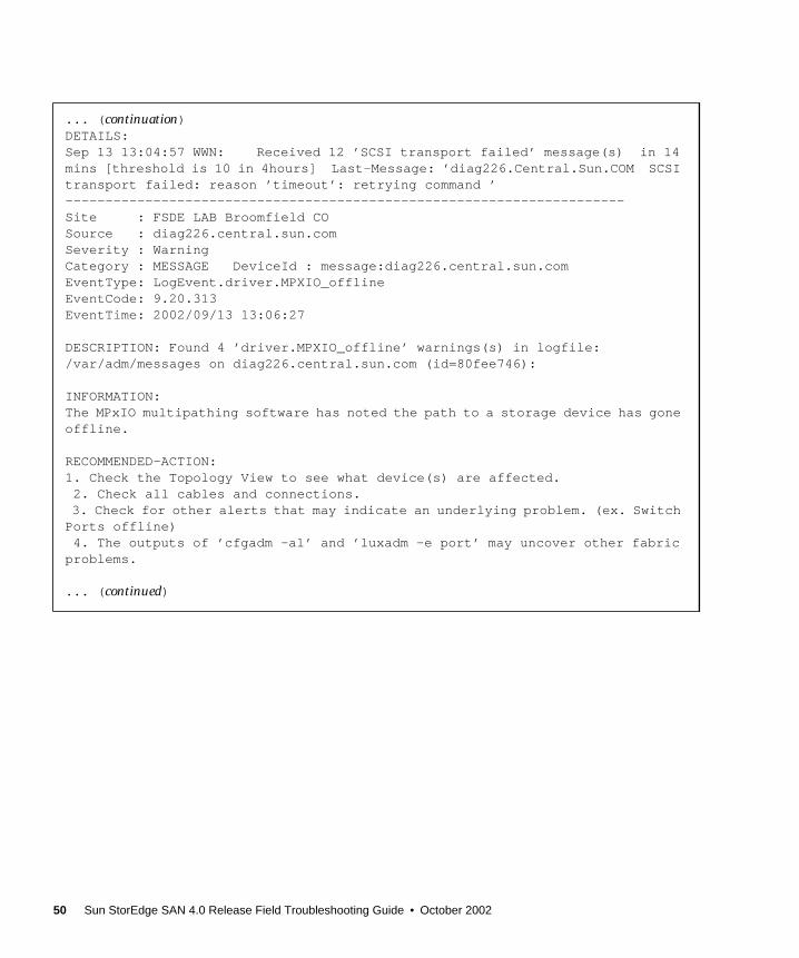
... (continuation)DETAILS:Sep 13 13:04:57 WWN: Received 12 ’SCSI transport failed’ message(s) in 14mins [threshold is 10 in 4hours] Last-Message: ’diag226.Central.Sun.COM SCSItransport failed: reason ’timeout’: retrying command ’----------------------------------------------------------------------Site : FSDE LAB Broomfield COSource : diag226.central.sun.comSeverity : WarningCategory : MESSAGE DeviceId : message:diag226.central.sun.comEventType: LogEvent.driver.MPXIO_offlineEventCode: 9.20.313EventTime: 2002/09/13 13:06:27
DESCRIPTION: Found 4 ’driver.MPXIO_offline’ warnings(s) in logfile:/var/adm/messages on diag226.central.sun.com (id=80fee746):
INFORMATION:The MPxIO multipathing software has noted the path to a storage device has goneoffline.
RECOMMENDED-ACTION:1. Check the Topology View to see what device(s) are affected. 2. Check all cables and connections.3. Check for other alerts that may indicate an underlying problem. (ex. SwitchPorts offline)4. The outputs of ’cfgadm -al’ and ’luxadm -e port’ may uncover other fabricproblems.
... (continued)
50 Sun StorEdge SAN 4.0 Release Field Troubleshooting Guide • October 2002
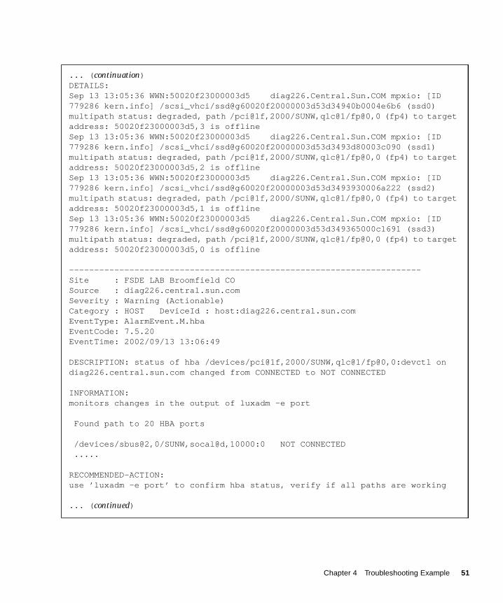
... (continuation)DETAILS:Sep 13 13:05:36 WWN:50020f23000003d5 diag226.Central.Sun.COM mpxio: [ID779286 kern.info] /scsi_vhci/ssd@g60020f20000003d53d34940b0004e6b6 (ssd0)multipath status: degraded, path /pci@1f,2000/SUNW,qlc@1/fp@0,0 (fp4) to targetaddress: 50020f23000003d5,3 is offlineSep 13 13:05:36 WWN:50020f23000003d5 diag226.Central.Sun.COM mpxio: [ID779286 kern.info] /scsi_vhci/ssd@g60020f20000003d53d3493d80003c090 (ssd1)multipath status: degraded, path /pci@1f,2000/SUNW,qlc@1/fp@0,0 (fp4) to targetaddress: 50020f23000003d5,2 is offlineSep 13 13:05:36 WWN:50020f23000003d5 diag226.Central.Sun.COM mpxio: [ID779286 kern.info] /scsi_vhci/ssd@g60020f20000003d53d3493930006a222 (ssd2)multipath status: degraded, path /pci@1f,2000/SUNW,qlc@1/fp@0,0 (fp4) to targetaddress: 50020f23000003d5,1 is offlineSep 13 13:05:36 WWN:50020f23000003d5 diag226.Central.Sun.COM mpxio: [ID779286 kern.info] /scsi_vhci/ssd@g60020f20000003d53d349365000c1691 (ssd3)multipath status: degraded, path /pci@1f,2000/SUNW,qlc@1/fp@0,0 (fp4) to targetaddress: 50020f23000003d5,0 is offline
----------------------------------------------------------------------Site : FSDE LAB Broomfield COSource : diag226.central.sun.comSeverity : Warning (Actionable)Category : HOST DeviceId : host:diag226.central.sun.comEventType: AlarmEvent.M.hbaEventCode: 7.5.20EventTime: 2002/09/13 13:06:49
DESCRIPTION: status of hba /devices/pci@1f,2000/SUNW,qlc@1/fp@0,0:devctl ondiag226.central.sun.com changed from CONNECTED to NOT CONNECTED
INFORMATION:monitors changes in the output of luxadm -e port
Found path to 20 HBA ports
/devices/sbus@2,0/SUNW,socal@d,10000:0 NOT CONNECTED .....
RECOMMENDED-ACTION:use ’luxadm -e port’ to confirm hba status, verify if all paths are working
... (continued)
Chapter 4 Troubleshooting Example 51

From the messages above, it is apparent that the following events occurred:
■ The u2ctlr took control of LUN 0 on t3b2
■ SSD and SCSI warnings were seen on host diag226
■ Sun StorEdge Traffic Manager Software has degraded the paths to a device withWWN 50020f23000003d5
■ One HBA went from CONNECTED to NOT CONNECTED
■ Port 0 on a Sun StorEdge 2 Gb FC switch (ip=172.20.67.84) went offline
... (continuation)----------------------------------------------------------------------
Site : FSDE LAB Broomfield COSource : diag226.central.sun.comSeverity : Error (Actionable)Category : SWITCH2 DeviceId : switch2:100000c0dd00bfdaEventType: StateChangeEvent.M.port.0EventCode: 12.26.35EventTime: 2002/09/13 13:06:35
DESCRIPTION: ’port.0’ in SWITCH2 sw-67-84 (ip=172.20.67.84) is now Not-Available (state changed from ’online’ to ’offline’):
INFORMATION:A port on the switch2 has logged out of the fabric and gone offline
RECOMMENDED-ACTION:1. Verify cables, GBICs and connections along Fibre Channel path2. Check SAN Topology GUI to identify failing segment of the data path3. Verify correct FC switch2 configuration
52 Sun StorEdge SAN 4.0 Release Field Troubleshooting Guide • October 2002
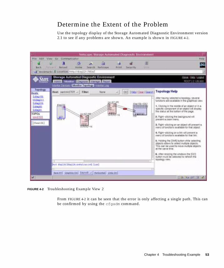
Determine the Extent of the ProblemUse the topology display of the Storage Automated Diagnostic Environment version2.1 to see if any problems are shown. An example is shown in FIGURE 4-2.
FIGURE 4-2 Troubleshooting Example View 2
From FIGURE 4-2 it can be seen that the error is only affecting a single path. This canbe confirmed by using the cfgadm command.
Chapter 4 Troubleshooting Example 53

1. Issue the cfgadm -al command to display the state and condition of allhardware attachment points.
The cfgadm output indicates that the c6::50020f230000003d5 device is unusable, butthe c7::50020f230000003c5 device is ok.
2. Issue the luxadm -e port command to query the status of the host ports usingthe expert mode (-e).
The luxadm -e port output shows that one of the HBAs has been affected. Thisleads to the conclusion that we have a single path problem, most likely affecting theHBA-to-switch link between /devices/pci@1f,2000/SUNW,qlc@1/fp@0,0 andport 0 of one switch.
# cfgadm -alAp_Id Type Receptacle Occupant Conditionc0 scsi-bus connected configured unknownc0::dsk/c0t0d0 disk connected configured unknownc0::dsk/c0t1d0 disk connected configured unknownc1 scsi-bus connected configured unknownc1::dsk/c1t6d0 CD-ROM connected configured unknownc2 fc connected unconfigured unknownc3 fc connected unconfigured unknownc4 fc-private connected unconfigured unknownc5 fc connected unconfigured unknownc6 fc-fabric connected configured unknownc6::50020f23000003d5 disk connected configured unusablec7 fc-fabric connected configured unknownc7::50020f23000003c5 disk connected configured unknownc8 fc connected unconfigured unknown
# luxadm -e port
Found path to 2 HBA ports
/devices/pci@1f,2000/SUNW,qlc@1/fp@0,0:devctl NOT CONNECTED/devices/pci@4,2000/SUNW,qlc@1/fp@0,0:devctl CONNECTED
54 Sun StorEdge SAN 4.0 Release Field Troubleshooting Guide • October 2002

Check the Array Status1. Telnet to the affected Sun StorEdgeg T3+ array (t3b2 in this example).
2. Issue the fru stat command to status the FRUs.
3. Issue the port list command to status the controllers.
4. Issue the port listmap command to determine the LUN mapping.
These command outputs indicate that both controllers are active, u2 owns all theLUNs, and WWN 50020f23000003d5 corresponds to the WWN of the MasterController. This confirms that the problem is most likely not with the Sun StorEdgeT3+ arrays. Thus, there is probably an upstream path problem.
t3b2:/:<2>fru statCTLR STATUS STATE ROLE PARTNER TEMP------ ------- ---------- ---------- ------- ----u1ctr ready enabled master u2ctr 41.5u2ctr ready enabled alt master u1ctr 39.0
t3b2:/:<3>port list
port targetid addr_type status host wwnu1p1 4 hard online sun 50020f23000003d5u2p1 5 hard online sun 50020f23000003c5
t3b2:/:<4>port listmap
port targetid addr_type lun volume owner accessu1p1 4 hard 0 vol1 u2 primaryu1p1 4 hard 1 vol1 u2 primaryu1p1 4 hard 4 vol1 u2 primaryu1p1 4 hard 2 vol2 u2 failoveru1p1 4 hard 3 vol2 u2 failoveru1p1 4 hard 5 vol2 u2 failoveru2p1 5 hard 0 vol1 u2 failoveru2p1 5 hard 1 vol1 u2 failoveru2p1 5 hard 4 vol1 u2 failoveru2p1 5 hard 2 vol2 u2 primaryu2p1 5 hard 3 vol2 u2 primaryu2p1 5 hard 5 vol2 u2 primary
Chapter 4 Troubleshooting Example 55

Check the Switch StatusView the Monitor Device display of the Storage Automated Diagnostic Environmentas shown in FIGURE 4-3.
FIGURE 4-3 Troubleshooting Example View 3
FIGURE 4-3 indicates that the problem is that the switch Port 0 has gone offline. It alsoshows that the only other device that is affected is the host. This indicates ahost-switch connection problem.
56 Sun StorEdge SAN 4.0 Release Field Troubleshooting Guide • October 2002

Test the FRUsThe following FRUs exist in the host-to-switch link:
■ Switch or switch port
■ Switch-side SFP
■ Cable
■ Host HBA
To isolate the cause, perform one of the following options with the StorageAutomated Diagnostics Environment:
■ The switchtest in combination with the qlctest
■ The linktest
Storage Automated Diagnostics Environment switchtestand qlctest Tests
1. Remove one end of the cable of the HBA-switch link
2. Insert loopback plug into the HBA
3. Run the qlctest
■ If the test fails, replace HBA and re-run the qlctest
■ If the test passes, continue below
4. Insert loopback plug into Switch SFP/Port
5. Run the switchtest
■ If the test passes, most likely problem is cable
■ If the test fails, continue below
6. Replace SFP and re-run the switchtest
■ If the test passes, the most likely problem was SFP connector
■ If the test fails, the most likely problem is the switch port or the entire switch
Chapter 4 Troubleshooting Example 57

Storage Automated Diagnostics Environment linktest TestOutput
running on diag221.central.sun.com linktest started on FC interconnect: fp to switch2 qlctest started on hba port "qlctest: called with options: dev=/devices/pci@1f,2000/SUNW,qlc@1/fp@0,0:devctl| run_connect=Yes| selftest=Disable| mbox=Disable| checksum=Disable| ilb_10=Disable| ilb=Disable| elb=Enable| iterations=100| xcnt=65536| selectpattern=critical| userpattern=0x7e7e7e7e" "qlctest: Started." "Program Version is 4.0.1" "Testing qlc0 device at /devices/pci@1f,2000/SUNW,qlc@1/fp@0,0:devctl." "QLC Subsystem ID = 0x106" 09/13/02 13:52:23 diag226.Central.Sun.COM MSGID 6028 qlctest.port_online.FATAL : "ERROR: Didn’t detect loop as being online and user selected external loopback option. Return code from checking path /devices/pci@1f,2000/SUNW,qlc@1/fp@0,0:devctl was 131337 "qlctest failed error code: 256 Remove FC Cable from hba: /devices/pci@1f,2000/SUNW,qlc@1/fp@0,0:devctl Insert FC Loopback Cable into hba: /devices/pci@1f,2000/SUNW,qlc@1/fp@0,0:devctl Continue Isolation ? qlctest started on hba port "qlctest: called with options: dev=/devices/pci@1f,2000/SUNW,qlc@1/fp@0,0:devctl| run_connect=Yes| selftest=Disable| mbox=Disable| checksum=Disable| ilb_10=Disable| ilb=Disable| elb=Enable| iterations=100| xcnt=65536| selectpattern=critical| userpattern=0x7e7e7e7e" "qlctest: Started." "Program Version is 4.0.1" "Testing qlc0 device at /devices/pci@1f,2000/SUNW,qlc@1/fp@0,0:devctl." "QLC Subsystem ID = 0x106" "QLC Adapter Chip Revision = 1, Risc Revision = 4, Frame Buffer Revision = 1287, Riscrom Revision = 1, Driver Revision = 6.0-2-1.17 "
... (continued)
58 Sun StorEdge SAN 4.0 Release Field Troubleshooting Guide • October 2002
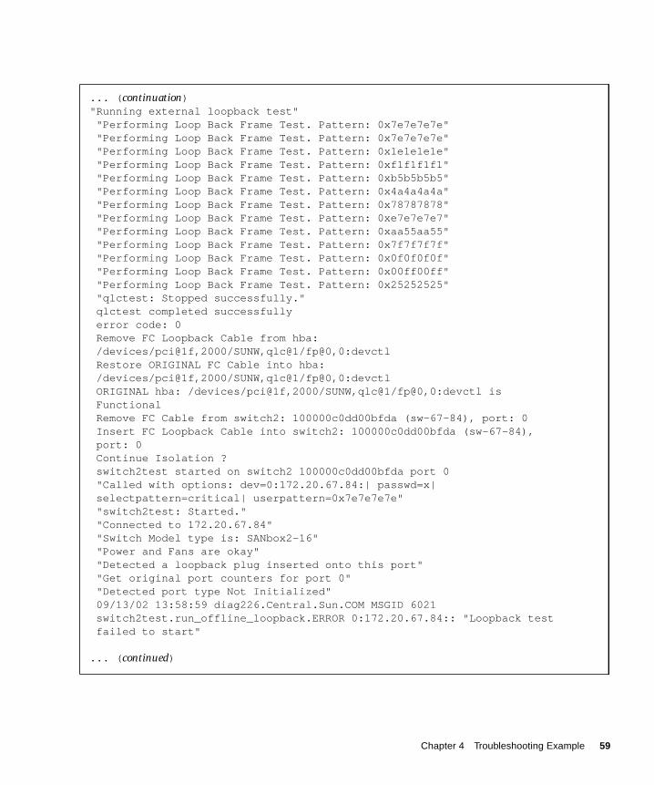
... (continuation)"Running external loopback test" "Performing Loop Back Frame Test. Pattern: 0x7e7e7e7e" "Performing Loop Back Frame Test. Pattern: 0x7e7e7e7e" "Performing Loop Back Frame Test. Pattern: 0x1e1e1e1e" "Performing Loop Back Frame Test. Pattern: 0xf1f1f1f1" "Performing Loop Back Frame Test. Pattern: 0xb5b5b5b5" "Performing Loop Back Frame Test. Pattern: 0x4a4a4a4a" "Performing Loop Back Frame Test. Pattern: 0x78787878" "Performing Loop Back Frame Test. Pattern: 0xe7e7e7e7" "Performing Loop Back Frame Test. Pattern: 0xaa55aa55" "Performing Loop Back Frame Test. Pattern: 0x7f7f7f7f" "Performing Loop Back Frame Test. Pattern: 0x0f0f0f0f" "Performing Loop Back Frame Test. Pattern: 0x00ff00ff" "Performing Loop Back Frame Test. Pattern: 0x25252525" "qlctest: Stopped successfully." qlctest completed successfully error code: 0 Remove FC Loopback Cable from hba: /devices/pci@1f,2000/SUNW,qlc@1/fp@0,0:devctl Restore ORIGINAL FC Cable into hba: /devices/pci@1f,2000/SUNW,qlc@1/fp@0,0:devctl ORIGINAL hba: /devices/pci@1f,2000/SUNW,qlc@1/fp@0,0:devctl is Functional Remove FC Cable from switch2: 100000c0dd00bfda (sw-67-84), port: 0 Insert FC Loopback Cable into switch2: 100000c0dd00bfda (sw-67-84), port: 0 Continue Isolation ? switch2test started on switch2 100000c0dd00bfda port 0 "Called with options: dev=0:172.20.67.84:| passwd=x| selectpattern=critical| userpattern=0x7e7e7e7e" "switch2test: Started." "Connected to 172.20.67.84" "Switch Model type is: SANbox2-16" "Power and Fans are okay" "Detected a loopback plug inserted onto this port" "Get original port counters for port 0" "Detected port type Not Initialized" 09/13/02 13:58:59 diag226.Central.Sun.COM MSGID 6021 switch2test.run_offline_loopback.ERROR 0:172.20.67.84:: "Loopback test failed to start"
... (continued)
Chapter 4 Troubleshooting Example 59
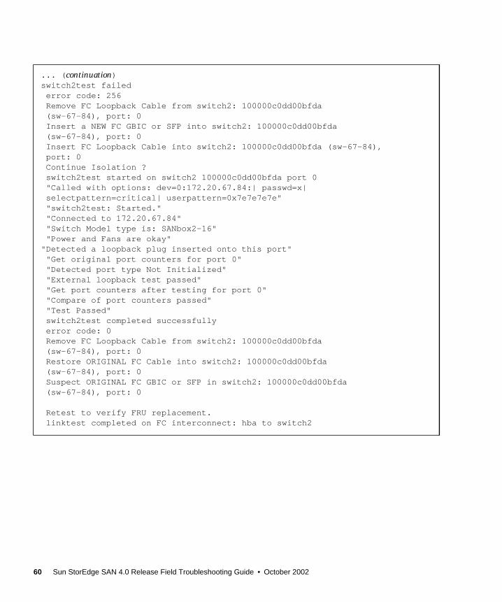
... (continuation)switch2test failed error code: 256 Remove FC Loopback Cable from switch2: 100000c0dd00bfda (sw-67-84), port: 0 Insert a NEW FC GBIC or SFP into switch2: 100000c0dd00bfda (sw-67-84), port: 0 Insert FC Loopback Cable into switch2: 100000c0dd00bfda (sw-67-84), port: 0 Continue Isolation ? switch2test started on switch2 100000c0dd00bfda port 0 "Called with options: dev=0:172.20.67.84:| passwd=x| selectpattern=critical| userpattern=0x7e7e7e7e" "switch2test: Started." "Connected to 172.20.67.84" "Switch Model type is: SANbox2-16" "Power and Fans are okay""Detected a loopback plug inserted onto this port" "Get original port counters for port 0" "Detected port type Not Initialized" "External loopback test passed" "Get port counters after testing for port 0" "Compare of port counters passed" "Test Passed" switch2test completed successfully error code: 0 Remove FC Loopback Cable from switch2: 100000c0dd00bfda (sw-67-84), port: 0 Restore ORIGINAL FC Cable into switch2: 100000c0dd00bfda (sw-67-84), port: 0 Suspect ORIGINAL FC GBIC or SFP in switch2: 100000c0dd00bfda (sw-67-84), port: 0
Retest to verify FRU replacement. linktest completed on FC interconnect: hba to switch2
60 Sun StorEdge SAN 4.0 Release Field Troubleshooting Guide • October 2002
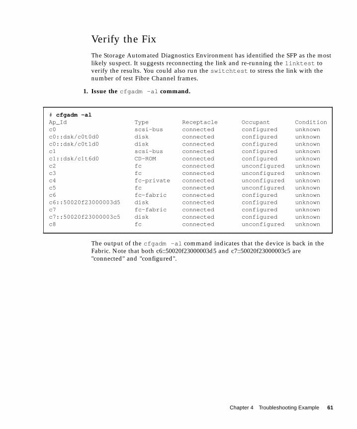
Verify the FixThe Storage Automated Diagnostics Environment has identified the SFP as the mostlikely suspect. It suggests reconnecting the link and re-running the linktest toverify the results. You could also run the switchtest to stress the link with thenumber of test Fibre Channel frames.
1. Issue the cfgadm -al command.
The output of the cfgadm -al command indicates that the device is back in theFabric. Note that both c6::50020f23000003d5 and c7::50020f23000003c5 are"connected" and "configured".
# cfgadm -alAp_Id Type Receptacle Occupant Conditionc0 scsi-bus connected configured unknownc0::dsk/c0t0d0 disk connected configured unknownc0::dsk/c0t1d0 disk connected configured unknownc1 scsi-bus connected configured unknownc1::dsk/c1t6d0 CD-ROM connected configured unknownc2 fc connected unconfigured unknownc3 fc connected unconfigured unknownc4 fc-private connected unconfigured unknownc5 fc connected unconfigured unknownc6 fc-fabric connected configured unknownc6::50020f23000003d5 disk connected configured unknownc7 fc-fabric connected configured unknownc7::50020f23000003c5 disk connected configured unknownc8 fc connected unconfigured unknown
Chapter 4 Troubleshooting Example 61
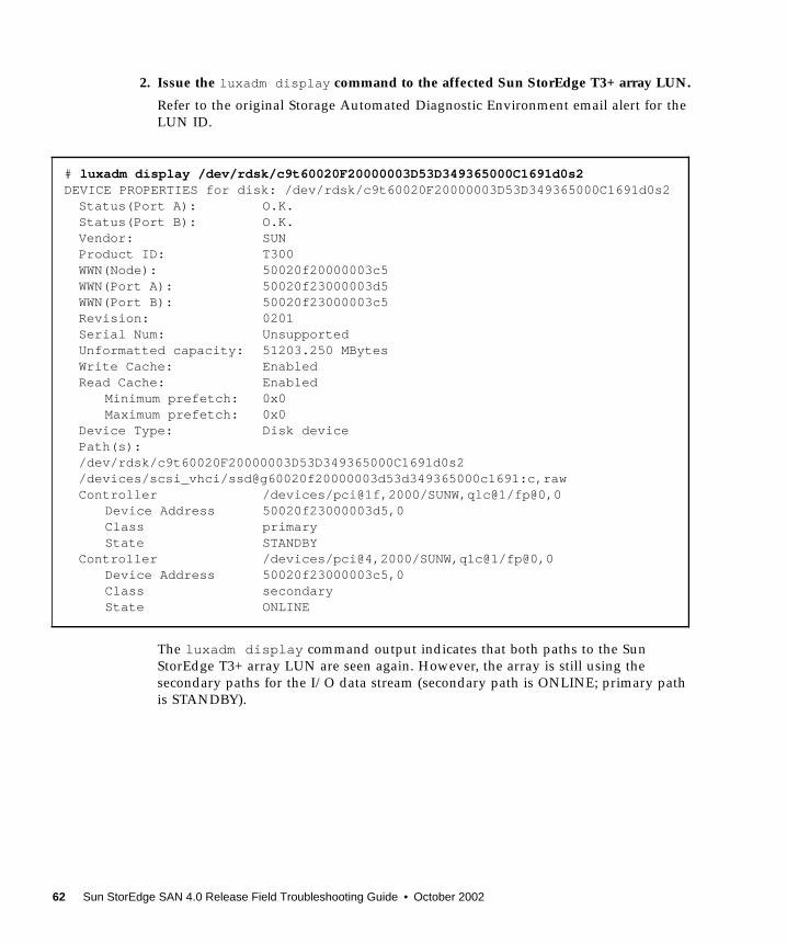
2. Issue the luxadm display command to the affected Sun StorEdge T3+ array LUN.
Refer to the original Storage Automated Diagnostic Environment email alert for theLUN ID.
The luxadm display command output indicates that both paths to the SunStorEdge T3+ array LUN are seen again. However, the array is still using thesecondary paths for the I/O data stream (secondary path is ONLINE; primary pathis STANDBY).
# luxadm display /dev/rdsk/c9t60020F20000003D53D349365000C1691d0s2DEVICE PROPERTIES for disk: /dev/rdsk/c9t60020F20000003D53D349365000C1691d0s2Status(Port A): O.K.Status(Port B): O.K.Vendor: SUNProduct ID: T300WWN(Node): 50020f20000003c5WWN(Port A): 50020f23000003d5WWN(Port B): 50020f23000003c5Revision: 0201Serial Num: UnsupportedUnformatted capacity: 51203.250 MBytesWrite Cache: EnabledRead Cache: Enabled
Minimum prefetch: 0x0Maximum prefetch: 0x0
Device Type: Disk devicePath(s):/dev/rdsk/c9t60020F20000003D53D349365000C1691d0s2/devices/scsi_vhci/ssd@g60020f20000003d53d349365000c1691:c,rawController /devices/pci@1f,2000/SUNW,qlc@1/fp@0,0
Device Address 50020f23000003d5,0Class primaryState STANDBY
Controller /devices/pci@4,2000/SUNW,qlc@1/fp@0,0Device Address 50020f23000003c5,0Class secondaryState ONLINE
62 Sun StorEdge SAN 4.0 Release Field Troubleshooting Guide • October 2002
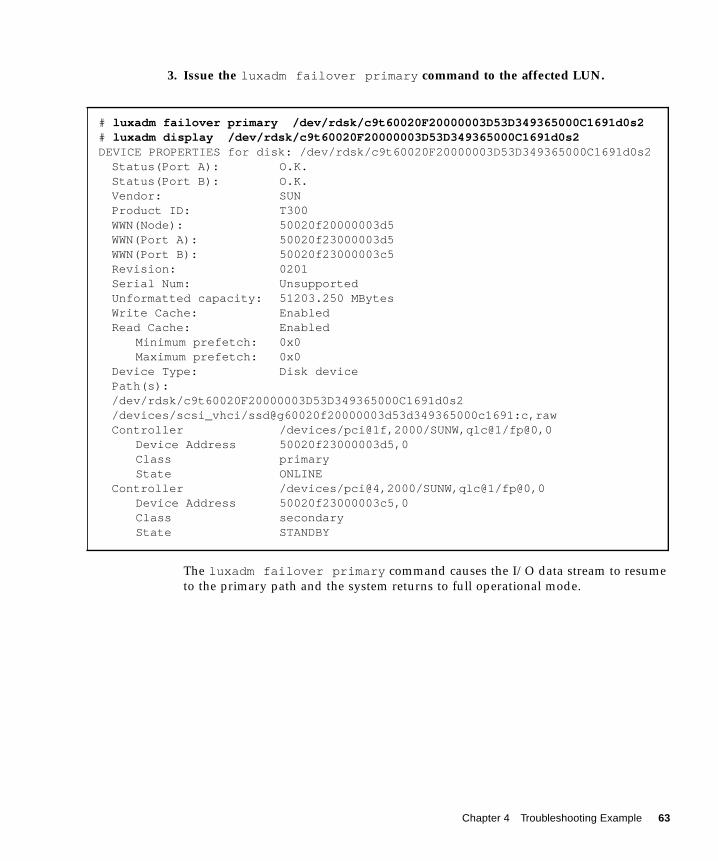
3. Issue the luxadm failover primary command to the affected LUN.
The luxadm failover primary command causes the I/O data stream to resumeto the primary path and the system returns to full operational mode.
# luxadm failover primary /dev/rdsk/c9t60020F20000003D53D349365000C1691d0s2# luxadm display /dev/rdsk/c9t60020F20000003D53D349365000C1691d0s2DEVICE PROPERTIES for disk: /dev/rdsk/c9t60020F20000003D53D349365000C1691d0s2Status(Port A): O.K.Status(Port B): O.K.Vendor: SUNProduct ID: T300WWN(Node): 50020f20000003d5WWN(Port A): 50020f23000003d5WWN(Port B): 50020f23000003c5Revision: 0201Serial Num: UnsupportedUnformatted capacity: 51203.250 MBytesWrite Cache: EnabledRead Cache: Enabled
Minimum prefetch: 0x0Maximum prefetch: 0x0
Device Type: Disk devicePath(s):/dev/rdsk/c9t60020F20000003D53D349365000C1691d0s2/devices/scsi_vhci/ssd@g60020f20000003d53d349365000c1691:c,rawController /devices/pci@1f,2000/SUNW,qlc@1/fp@0,0
Device Address 50020f23000003d5,0Class primaryState ONLINE
Controller /devices/pci@4,2000/SUNW,qlc@1/fp@0,0Device Address 50020f23000003c5,0Class secondaryState STANDBY
Chapter 4 Troubleshooting Example 63

64 Sun StorEdge SAN 4.0 Release Field Troubleshooting Guide • October 2002
APPENDIX A
Brocade Communications SystemsUpgrades and Installations
This appendix contains topics that describe how to install a new SAN system usingBrocade Communications Systems, Inc. Silkworm™ switch.
■ “Installing a New SAN” on page 66
■ “Downloading Patches and Packages” on page 67
■ “Installing the Software” on page 69
■ “Installing Firmware on Brocade Communications Systems Silkworm Switches”on page 72
■ “Upgrading the SAN” on page 76
65

Installing a New SAN
Required Software ComponentsThe following software components might be required for your particular SANsystem. Refer to the documentation for each individual product to insure properinstallation.
Software Components■ Sun StorEdge Traffic Manager
This is available as a patch which can be installed on Solaris 8 release 02/02(Update 7) or later. It should be installed with the latest revision of Sun StorEdgeNetwork Foundation Software.
■ Sun StorEdge Network Foundation Software
This software is included with the Solaris upgrades for the FC switch product. Itincludes the drivers to support switches, management tools and storage devices.
■ VERITAS Volume Manager
VERITAS Volume Manager is a separately installed software product that provideshost-based storage management, such a disk labeling, mirroring, striping, and RAID5.
■ Brocade Webtools
Brocade switches support Java-enabled Webtools. Brocade Webtools is a GUI thatprovides management capabilities, such as maintaining zones, setting portattributes, and setting up cascaded switches.
■ cfgadm plug-in for Fabric on-demand node creation
This component is delivered with the Solaris upgrades for the FC switch product. Itis used to discover SAN-attached devices, in addition to creating and deleting nodesfor these devices. These features are implemented through the cfgadm framework.See the cfgadm_fp(1M) man page for additional information.
■ luxadm and libg_fc/liba5k
These components are enhanced to support the SAN-attached devices. They providepersistent switch-attached device configuration across reboots, probe SAN-attacheddevices that are available on a host, and provide information on various devices.
66 Sun StorEdge SAN 4.0 Release Field Troubleshooting Guide • October 2002
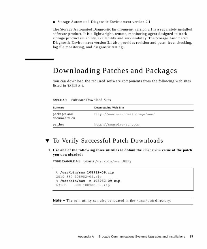
■ Storage Automated Diagnostic Environment version 2.1
The Storage Automated Diagnostic Environment version 2.1 is a separately installedsoftware product. It is a lightweight, remote, monitoring agent designed to trackstorage product reliability, availability and serviceability. The Storage AutomatedDiagnostic Environment version 2.1 also provides revision and patch level checking,log file monitoring, and diagnostic testing.
Downloading Patches and PackagesYou can download the required software components from the following web siteslisted in TABLE A-1.
▼ To Verify Successful Patch Downloads1. Use one of the following three utilities to obtain the checksum value of the patch
you downloaded:
CODE EXAMPLE A-1 Solaris /usr/bin/sum Utility
Note – The sum utility can also be located in the /usr/ucb directory.
TABLE A-1 Software Download Sites
Software Downloading Web Site
packages anddocumentation
http://www.sun.com/storage/san/
patches http://sunsolve/sun.com
% /usr/bin/sum 108982-09.zip2010 880 108982-09.zip% /usr/bin/sum -r 108982-09.zip63160 880 108982-09.zip
Appendix A Brocade Communications Systems Upgrades and Installations 67

CODE EXAMPLE A-2 Example of GNU md5sum Utility
Download the GNU md5sum utility from http://www.sunfreeware.com or fromhttp://sunsolve.Sun.com/md5/md5.tar.z.
2. Compare the checksum value that is displayed to the patch checksum valuegiven at the checksum File link:
http://sunsolve.Sun.com
If the values are identical, the patches were properly downloaded.
Note – The checksum file at http://sunsolve.Sun.com is approximately 614Kbytes.
% md5sum 108982-09.zip1297fcd385f618c726489c6c7f57c900 108982-09.zip
68 Sun StorEdge SAN 4.0 Release Field Troubleshooting Guide • October 2002
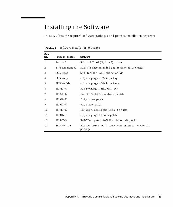
Installing the SoftwareTABLE A-2 lists the required software packages and patches installation sequence.
TABLE A-2 Software Installation Sequence
OrderNo. Patch or Package Software
1 Solaris 8 Solaris 8 02/02 (Update 7) or later
2 8_Recommended Solaris 8 Recommended and Security patch cluster
3 SUNWsan Sun StorEdge SAN Foundation Kit
4 SUNWcfpl cfgadm plug-in 32-bit package
5 SUNWcfplx cfgadm plug-in 64-bit package
6 111412-07 Sun StorEdge Traffic Manager
7 111095-07 fcp/fp/fctl/usoc drivers patch
8 111096-03 fcip driver patch
9 111097-07 qlc driver patch
10 111413-07 luxadm/liba5k and libg_fc patch
11 111846-03 cfgadm plug-in library patch
12 111847-04 SANWsan patch; SAN Foundation Kit patch
13 SUNWstade Storage Automated Diagnostic Environment version 2.1package
Appendix A Brocade Communications Systems Upgrades and Installations 69

▼ To Install the Software
Note – These instructions are to install the Sun StorEdge Network FoundationSoftware 6 patch.
1. Install Solaris 8 02/02 (Update 7) or later.
2. Install the latest Solaris 8 Recommended Security patch cluster.
See the README file for patch installation instructions and notes.
3. Install the SUNWsan package.
4. Install cfgadm plug-in library packages SUNWcfpl and SUNWcfplx.
5. Install the SAN Foundation Kit SUNWsan patch 111847-04, or higher, if required.
6. InstallSun StorEdge Traffic Manager patch 111412-07.
7. Install fctl/fp/fcp/usoc driver patch 111095-xx.
8. Install fcip driver patch.
9. Install qlc driver patch.
# pkgadd -d SUNWsan
# pkgadd -d pkg-location SUNWcfpl# pkgadd -d pkg-location SUNWcfplx
# patchadd 111412-07
# patchadd 111095-07
# patchadd 111096-03
# patchadd 111097-07
70 Sun StorEdge SAN 4.0 Release Field Troubleshooting Guide • October 2002
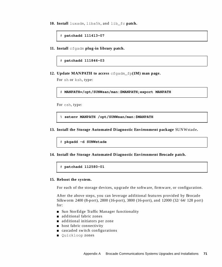
10. Install luxadm, liba5k, and lib_fc patch.
11. Install cfgadm plug-in library patch.
12. Update MANPATH to access cfgadm_fp(1M) man page.
For sh or ksh, type:
For csh, type:
13. Install the Storage Automated Diagnostic Environment package SUNWstade.
14. Install the Storage Automated Diagnostic Environment Brocade patch.
15. Reboot the system.
For each of the storage devices, upgrade the software, firmware, or configuration.
After the above steps, you can leverage additional features provided by BrocadeSilkworm 2400 (8-port), 2800 (16-port), 3800 (16-port), and 12000 (32/64/128 port)for:
■ Sun StorEdge Traffic Manager functionality■ additional fabric zones■ additional initiators per zone■ host fabric connectivity■ cascaded switch configurations■ Quickloop zones
# patchadd 111413-07
# patchadd 111846-03
# MANPATH=/opt/SUNWsan/man:$MANPATH;export MANPATH
% setenv MANPATH /opt/SUNWsan/man:$MANPATH
# pkgadd -d SUNWstade
# patchadd 112580-01
Appendix A Brocade Communications Systems Upgrades and Installations 71

Installing Firmware on BrocadeCommunications Systems SilkwormSwitches
▼ To Download Firmware from the Brocade WebSiteYou can locate and download Brocade firmware on a special website provided byBrocade. The URL for the Brocade site is site is http://www.brocade.com.
1. Click the Partners link.
2. Click the Brocade Partner Network link.
3. Enter the Sun-internal login.
Enter the Sun-internal password.
4. Under Services and Support, click Firmware.
5. Click the appropriate firmware version (see TABLE B-3).
6. Download the appropriate firmware version (see TABLE B-3—UNIX version) andthe Readme.txt file to your local host.
▼ To Install Firmware from UNIX (Solaris)Follow these steps:
1. From the Brocade web site, retrieve the switch firmware (for example, v2.6.x).
2. Download the firmware into your root (/) directory.
Note – Since UNIX contains rshd and cat daemons, you do not need to retrievethe rsh.ZIP file.
72 Sun StorEdge SAN 4.0 Release Field Troubleshooting Guide • October 2002
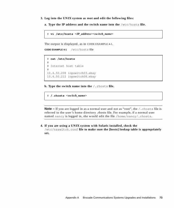
3. Log into the UNIX system as root and edit the following files:
a. Type the IP address and the switch name into the /etc/hosts file.
The output is displayed, as in CODE EXAMPLE 4-1.
CODE EXAMPLE 4-1 /etc/hosts file
b. Type the switch name into the /.rhosts file.
Note – If you are logged in as a normal user and not as “root”, the /.rhosts file isreferred to the user’s home directory .rhosts file. For example, if a normal usernamed nancy is logged in, she would edit the file /home/nancy/.rhosts.
4. If you are using a UNIX system with Solaris installed, check the/etc/nsswitch.conf file to make sure the [hosts] lookup table is appropriatelyset.
# vi /etc/hosts <IP_address><switch_name>
# cat /etc/hosts## Internet host table#10.4.50.208 iopswitch03.ebay10.4.50.212 iopswitch08.ebay
# /.rhosts <switch_name>
Appendix A Brocade Communications Systems Upgrades and Installations 73

▼ To Install Firmware using FTP
As an alternative to modifying the /.rhosts file, you can use the ftp method,which is explained below.
Note – You can invoke the command without any parameters, in which case you areprompted for input, including the choice of whether to use ftp or rshd.
If you invoke the command with three parameters, rshd is used. If you invoke thecommand with four parameters, ftp is used.
1. From a UNIX system, telnet into the switch and download the firmware with thefirmwareDownload command.
2. To check the syntax, type:
Note – With version 2.1 and higher, commands are not case-sensitive.
3. Check the syntax by typing firmwaredownload and following the screenprompts. See CODE EXAMPLE A-3 for an FTP example.
firmwareDownload
<Your UNIX IP address><Your UNIX Login user’s name></v2.4.1f><FTP_password>
help firmwareDownload
74 Sun StorEdge SAN 4.0 Release Field Troubleshooting Guide • October 2002
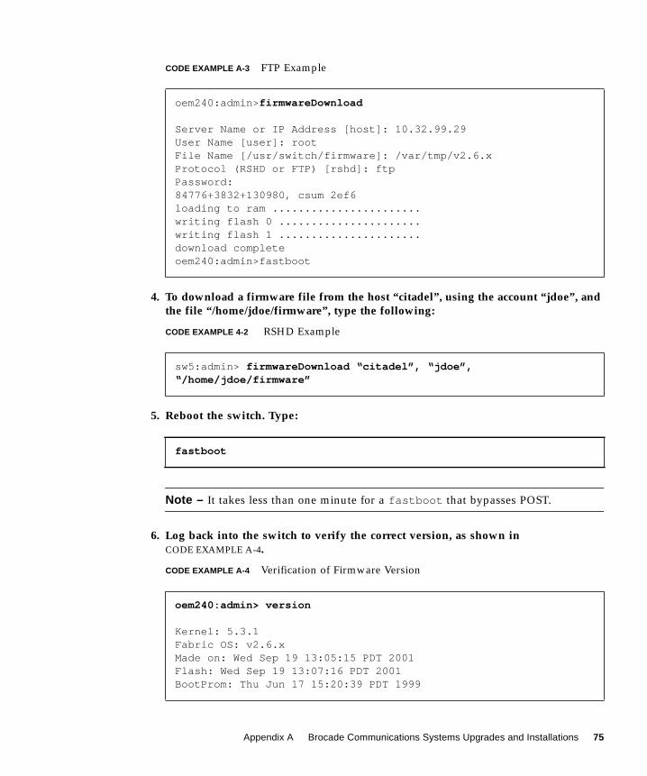
CODE EXAMPLE A-3 FTP Example
4. To download a firmware file from the host “citadel”, using the account “jdoe”, andthe file “/home/jdoe/firmware”, type the following:
CODE EXAMPLE 4-2 RSHD Example
5. Reboot the switch. Type:
Note – It takes less than one minute for a fastboot that bypasses POST.
6. Log back into the switch to verify the correct version, as shown inCODE EXAMPLE A-4.
CODE EXAMPLE A-4 Verification of Firmware Version
oem240:admin>firmwareDownload
Server Name or IP Address [host]: 10.32.99.29User Name [user]: rootFile Name [/usr/switch/firmware]: /var/tmp/v2.6.xProtocol (RSHD or FTP) [rshd]: ftpPassword:84776+3832+130980, csum 2ef6loading to ram .......................writing flash 0 ......................writing flash 1 ......................download completeoem240:admin>fastboot
sw5:admin> firmwareDownload “citadel”, “jdoe”,“/home/jdoe/firmware”
fastboot
oem240:admin> version
Kernel: 5.3.1Fabric OS: v2.6.xMade on: Wed Sep 19 13:05:15 PDT 2001Flash: Wed Sep 19 13:07:16 PDT 2001BootProm: Thu Jun 17 15:20:39 PDT 1999
Appendix A Brocade Communications Systems Upgrades and Installations 75
Upgrading the SANThis section contains topics about how to upgrade your SAN system to the latestversion.
Downloading Patches and PackagesDownload all patches and packages to the host prior to beginning the upgradeprocedure.
Verifying Upgrade ComplianceBefore starting the upgrade, insure that your system is stable and that all requiredsoftware and patches are accessible. Refer to TABLE B-1 on page 84 for thesupportability matrix.
▼ To Upgrade the SoftwareIf you have multiple hosts on your SAN, you can upgrade them simultaneously orone at a time without affecting your SAN environment. Hosts that are not beingupgraded will not be affected during the upgrade. You can upgrade the hostsoftware one host at a time or several hosts in parallel.
Caution – Your system will be unavailable to users and the SAN during theupgrade procedure.
The order in which the SAN components should be upgraded is as follows:
1. Familiarize yourself with the required software components, versions andpatches. Refer to Appendix B for the supportability matrix.
2. Back up all data.
76 Sun StorEdge SAN 4.0 Release Field Troubleshooting Guide • October 2002

Volume ManagementIf you are using VERITAS Volume Manager, refer to the VERITAS Volume ManagerInstallation Guide for special instructions about upgrading your system. There areseveral steps that need to be followed prior to your system upgrade.
1. Upgrade the Solaris Operating System.
To take advantage of full Fabric support for your SAN, you must upgrade to at leastSolaris 8 02/02 (Update 7). For information on how to upgrade your systems, referto Solaris 8 Installation Supplement, part number 806-5182, available athttp://docs.sun.com.
Sun StorEdge SAN 4.0 Release
The packages on your system that were previously used should be available. Toverify their availability, use the pkginfo command.
pkg_name is the name of the package on which you need to obtain the information.
1. Upgrade your SUNWsan package to Sun StorEdge SAN 4.0 Release.
Before you start, check your system to see if it has been installed, and if it is alreadyup to date. Use the pkginfo command to see if it has been installed.
# pkginfo -l pkg_name
# pkginfo SUNWsan
Appendix A Brocade Communications Systems Upgrades and Installations 77

The system returns:
The output indicates that the SUNWsan package has already been installed. If yoursystem has the SUNWsan package installed, use the showrev command to see if it isup-to-date.
The system returns:
The showrev results line indicates that the SUNWsan package is already up to date.If patch 111847-01 has not been installed, install it using the patchadd command.
2. If your system does not have the SUNWsan package installed, install the newSUNWsan package from your Sun StorEdge SAN 4.0 Release software.
cfgadm Plug-in Library Packages
1. Install cfgadm plug-in library packages SUNWcfpl and SUNWcfplx.
system SUNWsan SAN Foundation Kit
# showrev -p | grep 111847
Patch: 111847-01 Obsoletes: Requires: Incompatibles: Packages:SUNWsan
# patchadd patch-location/111847-04
# pkgadd -d pkg-location SUNWsan
# pkgadd -d pkg-location SUNWcfpl# pkgadd -d pkg-location SUNWcfplx pkgadd -d pkg-location SUNWcfplx
78 Sun StorEdge SAN 4.0 Release Field Troubleshooting Guide • October 2002
Software InstallationFor the Brocade Silkworm switch, the GUI capability is available through the switchfirmware and requires a Java-enabled browser on the host. Refer to “Related BrocadeDocumentation” in Appendix B for instructions on how to access Brocadedocumentation.
Note – Once the packages have successfully installed, follow steps 6 through 13 in“To Install the Software” on page 70.
▼ To Upgrade the Storage Automated DiagnosticEnvironment Version 2.1 Package
For all upgrades, you must first install the most recent Sun StorEdge NetworkFoundation Software patches. Refer to “To Install the Software” on page 70 forinstallation instructions before installing the SUNWstade package and the BrocadeCommunications Systems patch.
For detailed installation and usage instructions for the Storage AutomatedDiagnostic Environment version 2.1, refer to the Storage Automated DiagnosticEnvironment User’s Guide, Version 2.1.
1. If your SAN Management host is not running the current version, remove theexisting package and install the latest version. Remove the old package with thepkgrm command.
Removing the initial installation does not erase the previous configurationinformation. The cache and topology information of each device is also retained tomaintain a consistent, historical view of the Sun StorEdge devices.
2. Reinstall the package using the following command:
3. Run ras_install to enable the cron and to configure the agent as master orslave (a master agent acts as a collection point for events originating in other slaveagents).
4. Upgrade the master agent first.
# pkgrm SUNWstade
# pkgadd -d .
Appendix A Brocade Communications Systems Upgrades and Installations 79
5. Check your SAN Management host to verify the version of the Storage AutomatedDiagnostic Environment version 2.1 installed.
# pkginfo -l SUNWstade
80 Sun StorEdge SAN 4.0 Release Field Troubleshooting Guide • October 2002

APPENDIX B
Brocade Communications SystemsSwitch Troubleshooting
This appendix provides basic guidelines that you can use to isolate problems foundin a configuration using Brocade Communications Systems, Inc. Silkworm switches.It assumes you have been trained on all the components, such as storage andswitches, that make up the configuration.
The scope of this appendix is to highlight the differences of troubleshooting with aBrocade Silkworm configuration to that of a configuration that contains the currentSun StorEdge Network Fibre Channel family of switches. Current support is limitedto diagnosing failures down to the FRU level. In Sun’s support model, the entireSilkworm switch is considered a FRU. Many of Brocade’s internal diagnostics andmessages, while useful for depot or Root Cause Analysis situations, are notultimately relevant to a Sun Service Engineer trying to isolate to a FRU.
This appendix contains the following topics:
■ “Related Documentation” on page 82
■ “Supported Configurations” on page 83
■ “Diagnostic Tools” on page 87
■ “General Troubleshooting Procedures” on page 101
■ “Troubleshooting Case Study” on page 103
81

Related Documentation
Brocade Communications Systems Documentation
The following Brocade manuals are shipped on a CD with their related products.
■ Brocade Silkworm® 2400/2800 Hardware Reference Manual■ Brocade Silkworm® 3800 Hardware Reference■ Brocade Silkworm® 12000 Hardware Reference Manual■ Brocade Fabric OS™ Reference■ Brocade Fabric OS™ Release Notes■ Brocade Fabric OS™ Procedures Guide■ Brocade WebTools User’s Guide■ Brocade Zoning User’s Guide■ Brocade QuickLoop User’s Guide
Sun Documentation
The Sun StorEdge switch documents are referenced for overall configurationguidelines.
■ Sun StorEdge SAN 4.0 Release Installation Guide■ Sun StorEdge SAN 4.0 Release Configuration Guide■ Sun StorEdge SAN 4.0 Release Notes
82 Sun StorEdge SAN 4.0 Release Field Troubleshooting Guide • October 2002

Supported ConfigurationsThe Brocade Communications Systems Silkworm switch configurations and the SunStorEdge switch configurations follow the same rules for maximum number ofinitiators, supported number of arrays per zone, and other hardware-specificinformation.
Refer to Chapter 2, “Configurations” of this guide for supported hardwareconfigurations. Brocade Communications Systems Silkworm switch configurationsand Sun switch configurations have the minimum software package requirementsshown in TABLE B-1.
Appendix B Brocade Communications Systems Switch Troubleshooting 83

TABLE B-1 SAN Supportability Matrix with Solaris 8 02/02 (Update 7) or Later
ServerBus
Architecture HBAsPhysical
ConnectionRequired Sun Software Packages and
SAN 4.0/Brocade Patches
Sun Enterprise 3x00,6x00, and 10000
SBus X6757A1
1 Sun StorEdge SBus Dual Fibre Channel Host Bus Adapter (Ivory)
1-Gbyte FC Sun StorEdge Network FoundationSoftware 6.0 or later with thefollowing unbundled packages:• SUNWsan• SUNWcfpl• SUNWcfplxfound at the Download Center:http://www.sun.com/storage/san/ → Sun StorEdge SAN 4.0release Software/FirmwareUpgrades and Documentation →login → license agreement:• → Solaris 8 SUNWcfpl/x and
SUNWsan packages, or• → Solaris 9 SUNWcfpl/x and
SUNWsan packages
Sun StorEdge Traffic ManagerSoftware as part of Sun StorEdgeNetwork Foundation Software
Storage Automated DiagnosticEnvironment 2.1
To find all required patches:http://sunsolve.Sun.COM/→ Product Patches → PatchPro:• → Network Storage Products, or• → Solaris Recommended Patch
ClusterDescribe your system, then clickGenerate Patch List.
PCI X6799A2
X6727A3
2 Sun StorEdge PCI Single Fibre Channel Network Adapter (Amber)
3 Sun StorEdge PCI Dual Fibre Channel Network Adapter+ (Crystal+)
1-Gbyte FC
PCI X6767A4
X6768A5
4 Sun StorEdge 2G FC PCI Single Channel Network Adapter (Amber 2)
5 Sun StorEdge 2G FC PCI Dual Channel Network Adapter (Crystal+ 2)
2-Gbyte FC
Sun Fire 3800 cPCI X6748A6
6 Sun StorEdge cPCI Dual Fibre Channel Network Adapter (Diamond)
1-Gbyte FC
Sun Fire 4800—6800 cPCI X6748A 1-Gbyte FC
PCI X6799AX6727A
1-Gbyte FC
X6767AX6768A
2-Gbyte FC
Sun Fire 15k, 12k,E4x0, E2x0, SF480,SF280R, V880,SB1000, SB2000,Netra 1125 and 140X
PCI X6799AX6727A
1-Gbyte FC
X6767AX6768A
2-Gbyte FC
84 Sun StorEdge SAN 4.0 Release Field Troubleshooting Guide • October 2002

TABLE B-2 Disk Array Supportability Matrix with Solaris 8 02/02 (Update 7) or Later
Disk Arrays Disk Firmware
Dynamic addition of target to azone.
Add First/Additional
T3A WG/ES 1.18 Yes/Yes
T3B WG/ES 2.1 Yes/Yes
TABLE B-3 Fibre Channel Switch Supportability Matrix with Solaris 8 02/02 (Update 7)or Later
FC Switches Firmware Switch Software Licenses
Brocade Silkworm24001
1 Brocade Silkworm 2400, 2800, and 3800 FC Switches may be intermixed. Interoperabilitywith other vendor switches is not supported at this time.
v2.6.0c Fabric OSv2.6.0c
Zoning QuickloopWebtools
Brocade Silkworm2800
v2.6.0c Fabric OSv2.6.0c
Zoning QuickloopWebtools
Brocade Silkworm38002
2 Brocade Silkworm 3800 FC Switches are supported in the 1 and 2 Gbyte mode by auto-sensing.
v3.0.2c Fabric OSv3.0.2c
Zoning QuickloopWebtools
Brocade Silkworm12000
v4.0.0a Fabric OSv4.0.0a
Zoning QuickloopWebtools
Appendix B Brocade Communications Systems Switch Troubleshooting 85

1. Access the SunSolve web site.
http://sunsolve.Sun.COM/
The SUNSOLVE ONLINE menu is displayed.
2. Under SunSolve Contents, click Product Patches.
3. Under Patch Analysis Tools, click PatchPro.
4. Click Network Storage Product.
The PATCHPRO Interactive menu is displayed.
5. Select all the appropriate features of your system in the following areas of themenu:
■ OS Release■ Platform■ Disk Array■ Tape Libraries■ Disk Drives■ Tape Drives■ Switches and HBAs■ SAN Products | Brocade SAN Release■ Software
6. Click Generate Patch List.
TABLE B-4 Application Supportability Matrix with Solaris 8 02/02 (Update 7) or Later
Name Version Patches
VERITAS Volume Manager 3.2 GA To find all VERITAS Volume Managerpatches:http://sunsolve.Sun.COM/→ Product Patches → PatchPro→ Network Storage ProductsThen select:• OS Release• Platform• Software | Veritas Volume ManagerClick Generate Patch List.
86 Sun StorEdge SAN 4.0 Release Field Troubleshooting Guide • October 2002
QuickLoopQuickLoop is a feature of the Brocade Silkworm switches that allows hosts with hostbus adapters (HBAs) that are not fully Fabric-aware to communicate with otherdevices attached to the switch. In addition, QuickLoop allows switches to replacehubs in a private loop environment. QuickLoop is a separately licensed product.
Note – For the Brocade Sun StorEdge SAN 4.0 Release phase, Sun StorEdge T3 andT3+ arrays do not need Quickloop, nor do host bus adapters. Sun StorEdge T3 andT3+ arrays will auto-configure as L_Ports and HBAs will auto-configure as F_Ports ifthe switch is in the fabric mode.
Current Issues with the Storage AutomatedDiagnostic Environment Version 2.1 and BrocadeSwitchesThe minimum Brocade Silkworm switch firmware to use with Storage AutomatedDiagnostic Environment version 2.1 is v2.6.0c.
Diagnostic ToolsThe tools available for troubleshooting differ from the original release of the SunStorEdge SAN 4.0 Release. Since then, Sun StorEdge StorTools 4.x and NetworkStorage Agent 2.1 have had their functionality combined into a single diagnosticpackage called the Storage Automated Diagnostic Environment version 2.1. BrocadeSilkworm switches also have their own GUI called WebTools.
Storage Automated Diagnostic EnvironmentVersion 2.1 and Brocade SwitchesWith the Storage Automated Diagnostic Environment version 2.1, Brocade switchesare now supported under the same diagnostic framework as the rest of the Sun SANproduct family. This support includes monitoring for error and alert conditions,revision checking, graphic topology display, and fault isolation diagnostics.
Appendix B Brocade Communications Systems Switch Troubleshooting 87

brocadetest(1M)The Storage Automated Diagnostic Environment version 2.1 has incorporated thelaunching of various Brocade Silkworm switch diagnostic tests under one StorageAutomated Diagnostic Environment version 2.1 test, brocadetest(1M). This test islaunched within the Storage Automated Diagnostic Environment version 2.1framework and determines the correct Brocade specific test to run, depending onport type.
Example CLI brocadetest(1M)
# /opt/SUNWstade/Diags/bin/brocadetest -v -o "dev=5:172.20.67.167|passwd=password|iterations=1000"
Called with options: dev=5:172.20.67.167|passwd=xxxxxxx|iterations=1000Connect to 172.20.67.167Opened 172.20.67.167Logged into 172.20.67.167Clear port errors: send diagClearError 5Port errors clearedport is in loopback modeRunning command: CrossPortTest 1000,1Note: You should only have a loopback on port 5.If you have more than one loopback installed,this test may report false errors.Test PassedLoopback took 34 seconds to run.Fan #1 is OK, speed is 8640 RPMFan #2 is OK, speed is 8760 RPMFan #3 is OK, speed is 8910 RPMFan #4 is OK, speed is 8820 RPMFan #5 is OK, speed is 8820 RPMFan #6 is OK, speed is 8820 RPM
**********************************Detected possible bad Power supplyPower Supply #1 is absent**********************************
Power Supply #2 is OK
Close 172.20.67.167
88 Sun StorEdge SAN 4.0 Release Field Troubleshooting Guide • October 2002

Other Diagnostic ToolsBrocade Silkworm switches also support a wide range of CLI tests that can beinvoked while connected directly to the switch via a serial connection to theSilkworm 2400, by opening a telnet session, or by way of the front panel of theSilkworm 2800. Some of the tests pertinent for troubleshooting are listed below.
Storage Automated Diagnostic Environment’s brocadetest invokes crossPortTestfor testing loopback ports, spinFab for testing E-Port connections between switches,and loopPortTest for testing L Ports.
■ supportShow
■ switchShow
■ qlShow
■ diagShow
■ crossPortTest
■ loopPortTest
■ spinFab
■ nsShow
supportShow
supportShow runs nearly all commands and should be gathered when placing aservice call or escalation. The Explorer Data Collection utility, SUNWexplo, gathersthe supportShow output if the Brocade Silkworm switch is placed in the/opt/SUNWexplo/etc/saninput.txt
# Input file for extended data collection# Format is SWITCH SWITCH-TYPE PASSWORD LOGIN# Valid switch types are ancor and brocade# LOGIN is required for brocade switches, the default is admin172.20.67.167 brocade password admin172.20.67.164 brocade password admin
Appendix B Brocade Communications Systems Switch Troubleshooting 89

CODE EXAMPLE B-1 supportShow Sample Output
telnet> Trying 172.20.67.167...Connected to 172.20.67.167.Escape character is ’^]’.
Fabric OS (tm) Release v2.6.0
login: adminPassword:
diag167:admin> supportshow
Kernel: 5.4Fabric OS: v2.6.0Made on: Tue Jan 15 15:10:28 PST 2002Flash: Tue Jan 15 15:12:04 PST 2002BootProm: Thu Jun 17 15:20:39 PDT 1999
26 25 26 25 27 Centigrade 78 77 78 77 80 Fahrenheit
Power Supply #1 is absent
90 Sun StorEdge SAN 4.0 Release Field Troubleshooting Guide • October 2002

CODE EXAMPLE B-2 switchshow Example Output
CODE EXAMPLE B-3 qlshow Example Output
diag167:admin> switchshowswitchName: diag167switchType: 3.4switchState: OnlineswitchMode: NativeswitchRole: SubordinateswitchDomain: 1switchId: fffc01switchWwn: 10:00:00:60:69:20:1e:fcswitchBeacon: OFFZoning: ON (Main)port 0: sw Online E-Port 10:00:00:60:69:10:71:25 "diag164"(upstream)port 1: -- No_Moduleport 2: sw Online F-Port 21:01:00:e0:8b:23:61:f9port 3: -- No_Moduleport 4: -- No_Moduleport 5: -- No_Moduleport 6: sw Online E-Port 10:00:00:60:69:10:71:25 "diag164"port 7: sw Online F-Port 21:00:00:e0:8b:03:61:f9
diag167:admin> qlshowSelf: 10:00:00:60:69:20:1e:fc domain 1State: MasterScope: singleAL_PA bitmap: 30000000 00000000 00000000 00000000Local AL_PAs (not available)Local looplet states Member: 1 3 4 Online: - - - Looplet 1: offline Looplet 3: offline Looplet 4: offline
Appendix B Brocade Communications Systems Switch Troubleshooting 91

CODE EXAMPLE B-4 diagShow Example Output
CODE EXAMPLE B-5 crossPortTest Example Output
The "1000" is the number of passes, the "1" denotes singlePortAlso mode, whichallows the test to be run on a single port with a loopback connector plug inserted
diag167:admin> diagshownTicks: 0, Max: 4473924
Diagnostics Status: Tue Mar 19 14:04:30 2002
port#: 0 1 2 3 4 5 6 7diags: OK OK OK OK OK OK OK OKstate: UP DN UP DN DN DN UP UP
pt0: 4086880 frTx 64382622 frRx 0 LLI_errs. pt2: 38616950 frTx 300398 frRx 12 LLI_errs. pt6: 28852033 frTx 235091315 frRx 111 LLI_errs. pt7: 331090679 frTx 8930476 frRx 31 LLI_errs.
Central Memory OKTotal Diag Frames Tx: 8318Total Diag Frames Rx: 8911
diag167:admin> crossporttest 1000,1
Running Cross Port Test ....... passed.
92 Sun StorEdge SAN 4.0 Release Field Troubleshooting Guide • October 2002

CODE EXAMPLE B-6 loopPortTest Example Output
Note – Notes on loopPortTest
■ Syntax is loopporttest <num_passes>,<port>,<user_pattern>,<pattern_width>
■ Only works on logged in L-Ports
■ To test ports with Loopback connectors, use crossPortTest
CODE EXAMPLE B-7 spinFab Example Output
diag164:admin> loopporttest 100,2,0x7e7e7e7e,4Configuring L-port 2 to Cable Loopback Port........done.Will use pattern: 7e7e7e7e 7e7e7e7e 7e7e7e7e 7e7e7e7e
Running Loop Port Test ........ passed.
Configuring Loopback L-port(s) back to normal L-port(s).........done.
diag167:admin> spinfab 1,0,0
spinFab0 running...
spinFab0: Completed 1 megs, status: passed. port 0 test status: 0x00000000 -- passed.
Appendix B Brocade Communications Systems Switch Troubleshooting 93
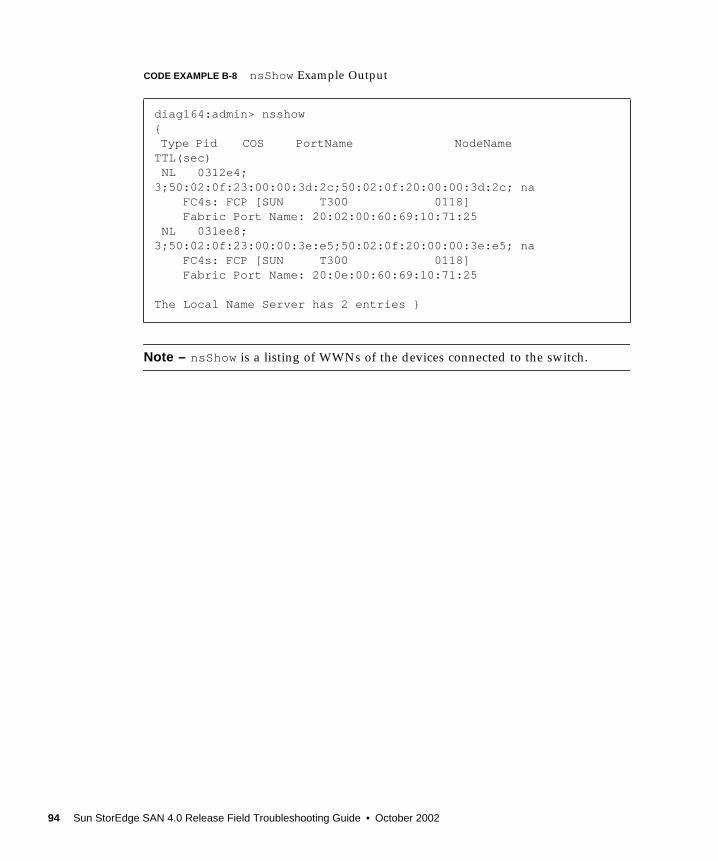
CODE EXAMPLE B-8 nsShow Example Output
Note – nsShow is a listing of WWNs of the devices connected to the switch.
diag164:admin> nsshow{Type Pid COS PortName NodeNameTTL(sec) NL 0312e4;3;50:02:0f:23:00:00:3d:2c;50:02:0f:20:00:00:3d:2c; na FC4s: FCP [SUN T300 0118] Fabric Port Name: 20:02:00:60:69:10:71:25 NL 031ee8;3;50:02:0f:23:00:00:3e:e5;50:02:0f:20:00:00:3e:e5; na FC4s: FCP [SUN T300 0118] Fabric Port Name: 20:0e:00:60:69:10:71:25
The Local Name Server has 2 entries }
94 Sun StorEdge SAN 4.0 Release Field Troubleshooting Guide • October 2002
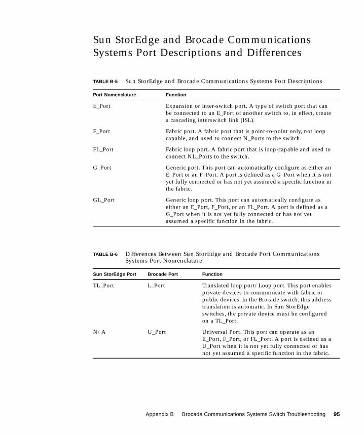
Sun StorEdge and Brocade CommunicationsSystems Port Descriptions and Differences
TABLE B-5 Sun StorEdge and Brocade Communications Systems Port Descriptions
Port Nomenclature Function
E_Port Expansion or inter-switch port. A type of switch port that canbe connected to an E_Port of another switch to, in effect, createa cascading interswitch link (ISL).
F_Port Fabric port. A fabric port that is point-to-point only, not loopcapable, and used to connect N_Ports to the switch.
FL_Port Fabric loop port. A fabric port that is loop-capable and used toconnect NL_Ports to the switch.
G_Port Generic port. This port can automatically configure as either anE_Port or an F_Port. A port is defined as a G_Port when it is notyet fully connected or has not yet assumed a specific function inthe fabric.
GL_Port Generic loop port. This port can automatically configure aseither an E_Port, F_Port, or an FL_Port. A port is defined as aG_Port when it is not yet fully connected or has not yetassumed a specific function in the fabric.
TABLE B-6 Differences Between Sun StorEdge and Brocade Port CommunicationsSystems Port Nomenclature
Sun StorEdge Port Brocade Port Function
TL_Port L_Port Translated loop port/Loop port. This port enablesprivate devices to communicate with fabric orpublic devices. In the Brocade switch, this addresstranslation is automatic. In Sun StorEdgeswitches, the private device must be configuredon a TL_Port.
N/A U_Port Universal Port. This port can operate as anE_Port, F_Port, or FL_Port. A port is defined as aU_Port when it is not yet fully connected or hasnot yet assumed a specific function in the fabric.
Appendix B Brocade Communications Systems Switch Troubleshooting 95
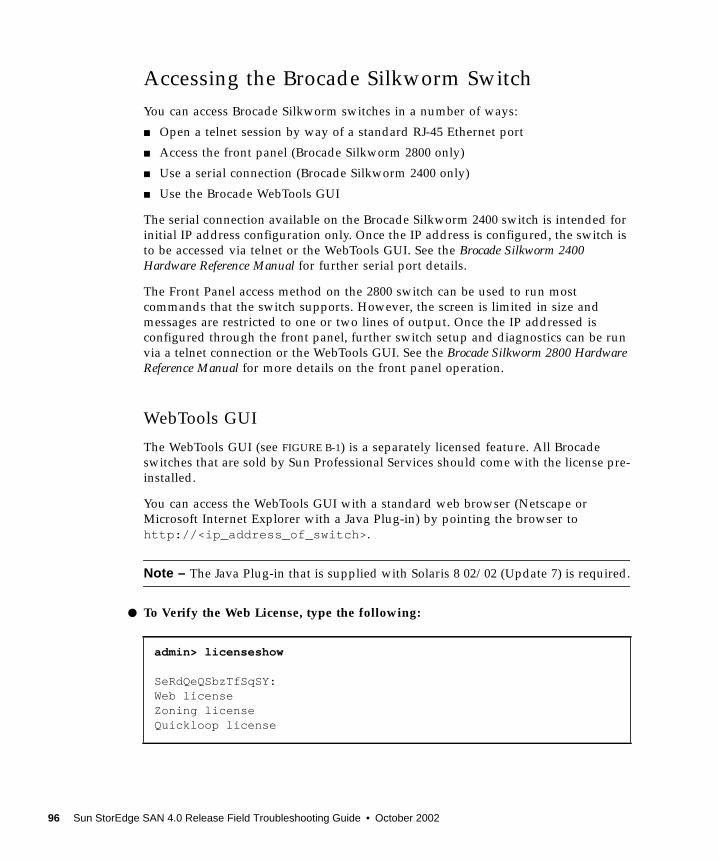
Accessing the Brocade Silkworm SwitchYou can access Brocade Silkworm switches in a number of ways:
■ Open a telnet session by way of a standard RJ-45 Ethernet port
■ Access the front panel (Brocade Silkworm 2800 only)
■ Use a serial connection (Brocade Silkworm 2400 only)
■ Use the Brocade WebTools GUI
The serial connection available on the Brocade Silkworm 2400 switch is intended forinitial IP address configuration only. Once the IP address is configured, the switch isto be accessed via telnet or the WebTools GUI. See the Brocade Silkworm 2400Hardware Reference Manual for further serial port details.
The Front Panel access method on the 2800 switch can be used to run mostcommands that the switch supports. However, the screen is limited in size andmessages are restricted to one or two lines of output. Once the IP addressed isconfigured through the front panel, further switch setup and diagnostics can be runvia a telnet connection or the WebTools GUI. See the Brocade Silkworm 2800 HardwareReference Manual for more details on the front panel operation.
WebTools GUI
The WebTools GUI (see FIGURE B-1) is a separately licensed feature. All Brocadeswitches that are sold by Sun Professional Services should come with the license pre-installed.
You can access the WebTools GUI with a standard web browser (Netscape orMicrosoft Internet Explorer with a Java Plug-in) by pointing the browser tohttp://<ip_address_of_switch>.
Note – The Java Plug-in that is supplied with Solaris 8 02/02 (Update 7) is required.
● To Verify the Web License, type the following:
admin> licenseshow
SeRdQeQSbzTfSqSY:Web licenseZoning licenseQuickloop license
96 Sun StorEdge SAN 4.0 Release Field Troubleshooting Guide • October 2002

FIGURE B-1 Brocade Webtools GUI
See the Brocade Web Tools User’s Guide for more information on WebTools usage.
Note – The rest of this guide will assume telnet usage.
Appendix B Brocade Communications Systems Switch Troubleshooting 97

Power On Self Test (POST)When the switch is powered up, it runs a series of POST tests including:
■ Dynamic RAM Test
■ Port Register Test
■ Central Memory Test
■ CMI Connector Test
■ CAM Test
■ Port Loop Back Test
POST behaves differently, depending on boot method. A power-cycle (power-off andpower-on) is considered a cold boot. All other boots from a powered-on state areconsidered warm boots.
POST execution per cold boot executes a longer version of the Memory Test. POSTexecution per warm boot executes a shorter version of Memory Test. Boot time withPOST varies, depending on boot method.
As the POST test successfully performs each test, a message “Passed” is displayedvia telnet on the front panel.
After the switch completes the POST, the port module returns to a steady state fromthe flashing state shown during tests.
If a yellow port module light is displayed or is slowly flashing, this indicates that theport is in a failed state.
Should the switch fail to complete POST, the green power LED will be set to blink.This indicates that the switch failed one of the initial stages of POST and that theCPU is not able to bring up the operating system. Should this occur, replace theswitch.
98 Sun StorEdge SAN 4.0 Release Field Troubleshooting Guide • October 2002

Removing Power
Caution – Error messages are stored in RAM and are lost when power is removedfrom the switch. Capture and view the error log output and note any error messagesbefore removing power.
Status and Activity Indicators
Front Panel LED Port Indicators
See the Brocade Silkworm Hardware Reference Manual for further details.
Front Panel LEDs Definition
No light showing No light or signal carrier (no module, no cable) formedia interface LEDs
Steady yellow Receiving light or signal, but not yet online
Slow1 yellow Disabled (result of diagnostics or portDisablecommand). Flashes every two seconds.
Fast2 yellow Error, fault with port. Flashes every 1/2 second.
Steady green Online (connected with device)
Slow1 green Online, but segmented (loopback cable orincompatible switch) flashes every two seconds.
Fast2 green Internal loopback (diagnostics). Flashes every 1/2second.
Flickering green Online and frames flowing through port.
1Slow —2 seconds interval2Fast — 1/2 second interval
Appendix B Brocade Communications Systems Switch Troubleshooting 99

Initialization Steps:
At power-on or reset, the following steps occur.
1. Preliminary POST diagnostics.
2. VxWorks operating system initialization.
3. Hardware initialization (resets, internal addresses assigned to ASICs, serial portinitialized, front panel initialized).
4. Full POST test.
5. Universal Port Configuration.
6. Link initialization—receiver/transmitter negotiation to bring connected portsonline.
7. Fabric analysis—the switch checks for ports connected to other Fabric elements. Ifthere are other Fabric elements connected, it identifies the master switch.
8. Address assignment—once the master switch has been identified, port addressesmay be assigned. Each switch tries to keep the same addresses that werepreviously used. These are stored in the switch’s configuration flash PROM.
9. Routing table construction—after addresses are assigned, the unicast routingtables are constructed.
10. Enable normal port operation.
Note – If any of the steps listed above fails, replace the entire switch as a singleFRU.
100 Sun StorEdge SAN 4.0 Release Field Troubleshooting Guide • October 2002
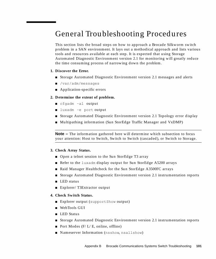
General Troubleshooting ProceduresThis section lists the broad steps on how to approach a Brocade Silkworm switchproblem in a SAN environment. It lays out a methodical approach and lists varioustools and resources available at each step. It is expected that using StorageAutomated Diagnostic Environment version 2.1 for monitoring will greatly reducethe time consuming process of narrowing down the problem.
1. Discover the Error.
■ Storage Automated Diagnostic Environment version 2.1 messages and alerts
■ /var/adm/messages
■ Application-specific errors
2. Determine the extent of problem.
■ cfgadm -al output
■ luxadm -e port output
■ Storage Automated Diagnostic Environment version 2.1 Topology error display
■ Multipathing information (Sun StorEdge Traffic Manager and VxDMP)
Note – The information gathered here will determine which subsection to focusyour attention: Host to Switch, Switch to Switch (cascaded), or Switch to Storage.
3. Check Array Status.
■ Open a telnet session to the Sun StorEdge T3 array
■ Refer to the luxadm display output for Sun StorEdge A5200 arrays
■ Raid Manager Healthcheck for the Sun StorEdge A3500FC arrays
■ Storage Automated Diagnostic Environment version 2.1 instrumentation reports
■ LED status
■ Explorer/T3Extractor output
4. Check Switch Status.
■ Explorer output (supportShow output)
■ WebTools GUI
■ LED Status
■ Storage Automated Diagnostic Environment version 2.1 instrumentation reports
■ Port Modes (F/L/E, online, offline)
■ Nameserver Information (nsshow, nsallshow)
Appendix B Brocade Communications Systems Switch Troubleshooting 101

5. Start Testing FRUS.
■ Storage Automated Diagnostic Environment version 2.1 tests, such as thebrocadetest(1M), qlctest(1M), t3test(1M), linktest(1M), anda5ktest(1M).
■ Brocade CLI tests (loopPortTest, spinFab, crossPortTest)
■ Sun StorEdge T3 Array tests, such as T3OFDG(1M)
■ Sun StorEdge A3500FC arrays Healthcheck
Note – The conclusion of these tests isolate the problem to a FRU to be replaced.Follow the appropriate hardware manual for proper FRU replacement procedures.
6. Verify the fix.
■ /var/adm/messages (path online, multipath informational messages)
■ Storage Automated Diagnostic Environment version 2.1 status
■ Sun StorEdge Traffic Manager or VxDMP, to return the path to its normal state
102 Sun StorEdge SAN 4.0 Release Field Troubleshooting Guide • October 2002

Troubleshooting Case StudyThe following case study illustrates a practical application of the steps outlinedabove. This is only one way to approach the problem; there may be others.
Note – Knowledge and training on all components in a SAN are prerequisitesbefore you attempt the procedures below.
In this test case, the I/O load was generated using the dex disk exerciser to simulatecustomer load, and the steps below allowed the I/O to continue uninterruptedthroughout the procedure.
Configuration■ Sun Fire V880
■ Solaris 8 02/02 (Update 7) with all recommended and latest Sun StorEdgeNetwork Foundation Software patches
■ Sun StorEdge T3 array Partner Pair with FW 1.18
■ Brocade Silkworm 2400 and 2800 switches with v2.6.0 firmware
■ Storage Automated Diagnostic Environment version 2.1 with the latest patches
Note – The Storage Automated Diagnostic Environment version 2.1 was configuredto send email alerts to a system administrator’s email address.
Appendix B Brocade Communications Systems Switch Troubleshooting 103
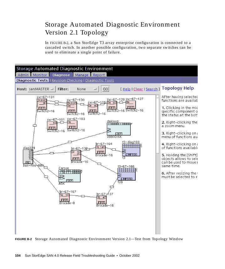
Storage Automated Diagnostic EnvironmentVersion 2.1 TopologyIn FIGURE B-2, a Sun StorEdge T3 array enterprise configuration is connected to acascaded switch. In another possible configuration, two separate switches can beused to eliminate a single point of failure.
FIGURE B-2 Storage Automated Diagnostic Environment Version 2.1—Test from Topology Window
104 Sun StorEdge SAN 4.0 Release Field Troubleshooting Guide • October 2002

1. Discover the Error using Storage Automated Diagnostic Environment Alerts asshown in FIGURE B-3.
Site : Lab BroomSource : diag229.central.sun.comSeverity : Error (Actionable)Category : BROCADE DeviceId : brocade:1000006069201efcEventType: StateChangeEvent.M.port.2EventCode: 5.26.35EventTime: 2002/07/11 10:32:33
’port.2’ in BROCADE br-67-167 (ip=172.20.67.167) is now Not-Available (state changed from’online’ to ’offline’):
INFORMATION:A port on the switch has logged out of the fabric and gone offline
RECOMMENDED-ACTION:1. Verify cables, GBICs and connections along Fibre Channel path2. Check SAN Topology GUI to identify failing segment of the data path3. Verify correct FC switch configuration4. Verify port is enabled
----------------------------------------------------------------------Site : Lab BroomSource : diag229.central.sun.comSeverity : Error (Actionable)Category : MESSAGE DeviceId : message:diag229.central.sun.comEventType: LogEvent.driver.QLC_LOOP_OFFLINEEventCode: 9.20.315EventTime: 2002/07/11 10:32:45
Found 1 ’driver.QLC_LOOP_OFFLINE’ errors(s) in logfile: /var/adm/messages ondiag229.central.sun.com (id=80c61254):
INFORMATION:Found Loop OFFLINE message. This could indicate that a fiber channel cable has been removed. This could indicate troubles with a fiber channel loop. This could also be caused by running the qlctest.
RECOMMENDED-ACTION:1. Check to see if a fiber channel cable has been removed.2. Check for fiber channel errors.3. Check to see if the qlctest was running at time of the failure.
----------------------------------------------------------------------
[continued on next page]
Appendix B Brocade Communications Systems Switch Troubleshooting 105

[continued from previous page]
Jul 11 10:31:12WWN:Received 1 ’Loop Offline’ message(s) in 7 mins [threshold is 1 in5mins] Last-Message: ’diag229.Central.Sun.COM qlc: [ID 686697 kern.info] NOTICE: Qlogicqlc(4): Loop OFFLINE ’
----------------------------------------------------------------------Site : Lab BroomSource : diag229.central.sun.comSeverity : Error (Actionable)Category : HOST DeviceId : host:diag229.central.sun.comEventType: AlarmEvent.M.lun.T300.c3t50020F23000068CCd0s2.statusAEventCode: 7.5.27EventTime: 2002/07/11 10:35:08
The state of ’lun.T300.c3t50020F23000068CCd0s2.statusA’ on diag229.central.sun.comchanged from ’O.K.’ to ’Missing’ (target=t3:t3-67-166/172.20.67.166)
INFORMATION:luxadm display reported a change in the port-status of one of it’s paths. The agent then tries to find which enclosure this path corresponds to by reviewing it’s database of T3’s and VE’s.
luxadm display 2a00006022004188 DEVICE PROPERTIES for disk: 2a00006022004188 Status(Port A): O.K. **** monitoring this field. Vendor: SUN Product ID: SESS01 WWN(Node): 2a00006022004188 WWN(Port A): 2b00006022004188 Revision: 080D Serial Num: Unsupported Unformatted capacity: 241724.000 MBytes Write Cache: Enabled Read Cache: Enabled Minimum prefetch: 0x0 Maximum prefetch: 0x0 Device Type: Disk device Path(s): /dev/rdsk/c7t2B00006022004188d0s2 /devices/sbus@8,0/SUNW,qlc@1,30000/fp@0,0/ssd@w2b00006022004188,0:c,raw
----------------------------------------------------------------------
[continued on next page]
106 Sun StorEdge SAN 4.0 Release Field Troubleshooting Guide • October 2002

FIGURE B-3 Storage Automated Diagnostic Environment Alert
This alert shows:
■ An error on port two of switch 172.20.67.167 occurred
■ A Sun StorEdge Traffic Manager offline event occurred
■ The HBA is offline
[continued from previous page]
Site : Lab BroomSource : diag229.central.sun.comSeverity : Error (Actionable)Category : HOST DeviceId : host:diag229.central.sun.comEventType: AlarmEvent.M.lun.T300.c3t50020F23000068CCd1s2.statusAEventCode: 7.5.27EventTime: 2002/07/11 10:35:08
The state of ’lun.T300.c3t50020F23000068CCd1s2.statusA’ on diag229.central.sun.comchanged from ’O.K.’ to ’Missing’ (target=t3:t3-67-166/172.20.67.166)
INFORMATION:luxadm display reported a change in the port-status of one of it’s paths. The agent then tries to find which enclosure this path corresponds to by reviewing it’s database of T3’s and VE’s.
luxadm display 2a00006022004188 DEVICE PROPERTIES for disk: 2a00006022004188 Status(Port A): O.K. **** monitoring this field. Vendor: SUN Product ID: SESS01 WWN(Node): 2a00006022004188 WWN(Port A): 2b00006022004188 Revision: 080D Serial Num: Unsupported Unformatted capacity: 241724.000 MBytes Write Cache: Enabled Read Cache: Enabled Minimum prefetch: 0x0 Maximum prefetch: 0x0 Device Type: Disk device Path(s): /dev/rdsk/c7t2B00006022004188d0s2 /devices/sbus@8,0/SUNW,qlc@1,30000/fp@0,0/ssd@w2b00006022004188,0:c,raw
----------------------------------------------------------------------
Appendix B Brocade Communications Systems Switch Troubleshooting 107

2. Determine the extent of the problem using cfgadm -al output.
CODE EXAMPLE B-9 cfgadm -al output to check OS level fabric condition
The device on c3 has disappeared. In addition, the luxadm output of the SunStorEdge T3 arrays shows the following.
# cfgadm -al
c3 fc-fabric connected configured unknownc3::50020f23000068cc unavailable connected configured unusablec4 fc-private connected unconfigured unknownc5 fc-fabric connected configured unknownc5::210000e08b05041c unknown connected unconfigured unknownc5::50020f2300004331 disk connected configured unknown
# luxadm display /dev/rdsk/c6t60020F2000003EE53AAF7A09000DA257d0s2
/: luxadm display 50020f23000068cc
Error: Invalid pathname (50020f23000068cc)/:
108 Sun StorEdge SAN 4.0 Release Field Troubleshooting Guide • October 2002
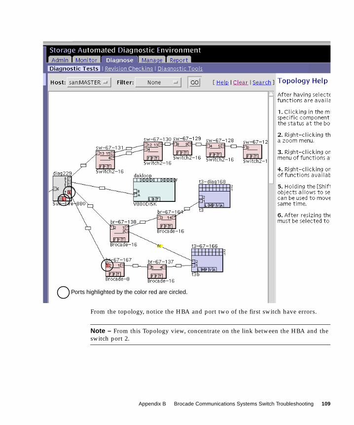
From the topology, notice the HBA and port two of the first switch have errors.
Note – From this Topology view, concentrate on the link between the HBA and theswitch port 2.
Ports highlighted by the color red are circled.
Appendix B Brocade Communications Systems Switch Troubleshooting 109
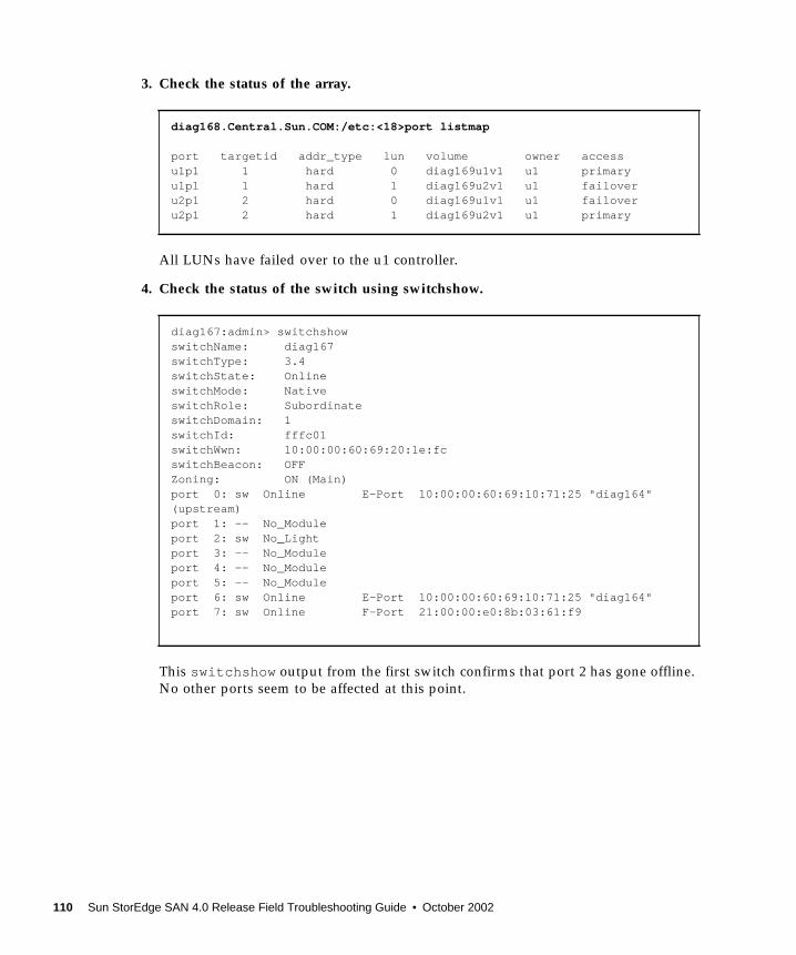
3. Check the status of the array.
All LUNs have failed over to the u1 controller.
4. Check the status of the switch using switchshow.
This switchshow output from the first switch confirms that port 2 has gone offline.No other ports seem to be affected at this point.
diag168.Central.Sun.COM:/etc:<18>port listmap
port targetid addr_type lun volume owner accessu1p1 1 hard 0 diag169u1v1 u1 primaryu1p1 1 hard 1 diag169u2v1 u1 failoveru2p1 2 hard 0 diag169u1v1 u1 failoveru2p1 2 hard 1 diag169u2v1 u1 primary
diag167:admin> switchshowswitchName: diag167switchType: 3.4switchState: OnlineswitchMode: NativeswitchRole: SubordinateswitchDomain: 1switchId: fffc01switchWwn: 10:00:00:60:69:20:1e:fcswitchBeacon: OFFZoning: ON (Main)port 0: sw Online E-Port 10:00:00:60:69:10:71:25 "diag164"(upstream)port 1: -- No_Moduleport 2: sw No_Lightport 3: -- No_Moduleport 4: -- No_Moduleport 5: -- No_Moduleport 6: sw Online E-Port 10:00:00:60:69:10:71:25 "diag164"port 7: sw Online F-Port 21:00:00:e0:8b:03:61:f9
110 Sun StorEdge SAN 4.0 Release Field Troubleshooting Guide • October 2002

5. Use the Link Test to check the FRUs.
In the Switch-to-HBA link there are potentially four FRUs:
■ HBA■ Cable■ Switch SFP■ Switch chassis
Note – Before starting the Link Test, you must enter the password for the Brocadeswitch in the configuration menu.
a. Using the Storage Automated Diagnostic Environment version 2.1, right-clickon the box on the link that connects the HBA and switch port.
A pop-up menu appears.
b. From the menu, click on Start Link Test.
The Link Test components are displayed on the right side of the window. SeeFIGURE B-4.
Appendix B Brocade Communications Systems Switch Troubleshooting 111
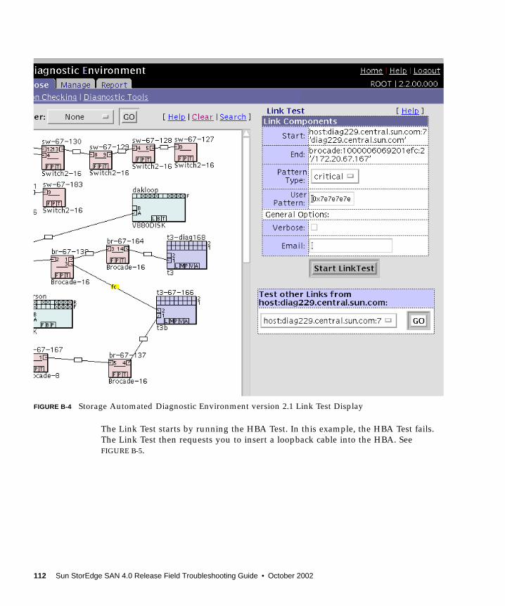
FIGURE B-4 Storage Automated Diagnostic Environment version 2.1 Link Test Display
The Link Test starts by running the HBA Test. In this example, the HBA Test fails.The Link Test then requests you to insert a loopback cable into the HBA. SeeFIGURE B-5.
112 Sun StorEdge SAN 4.0 Release Field Troubleshooting Guide • October 2002
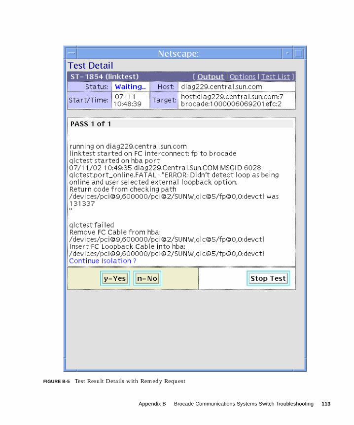
FIGURE B-5 Test Result Details with Remedy Request
Appendix B Brocade Communications Systems Switch Troubleshooting 113

The Link Test then runs the HBA Test again. This time the HBA Test succeeds andyou are requested to reconnect the loopback cable into the HBA, as shown inFIGURE B-6.
FIGURE B-6 Test Result Details Showing a Successful Test
114 Sun StorEdge SAN 4.0 Release Field Troubleshooting Guide • October 2002

The Link Test new runs the Switch Port Test. In this example, the Switch Port Testpasses. The Link Test then requests you to insert a new fiber cable between the HBAand the Brocade switch port as shown in FIGURE B-7.
FIGURE B-7 Continued Link Test Example Results
Appendix B Brocade Communications Systems Switch Troubleshooting 115
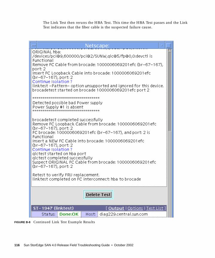
The Link Test then reruns the HBA Test. This time the HBA Test passes and the LinkTest indicates that the fiber cable is the suspected failure cause.
FIGURE B-8 Continued Link Test Example Results
116 Sun StorEdge SAN 4.0 Release Field Troubleshooting Guide • October 2002
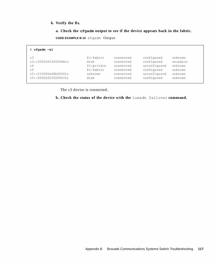
6. Verify the fix.
a. Check the cfgadm output to see if the device appears back in the fabric.
CODE EXAMPLE B-10 cfgadm Output
The c3 device is connected.
b. Check the status of the device with the luxadm failover command.
# cfgadm -al
c3 fc-fabric connected configured unknownc3::50020f23000068cc disk connected configured unusablec4 fc-private connected unconfigured unknownc5 fc-fabric connected configured unknownc5::210000e08b05041c unknown connected unconfigured unknownc5::50020f2300004331 disk connected configured unknown
Appendix B Brocade Communications Systems Switch Troubleshooting 117

The primary path is now restored as the ONLINE path and I/O is again using thispath. As a final check, look to the Storage Automated Diagnostic Environmentversion 2.1 topology. The ports that were in error are now green and the [mpx] erroris green as well, as shown in FIGURE B-9.
# luxadm failover primary
/home/mckenney/ws/storade2.2/StorTools/tests/discover: luxadm display50020f23000068ccDEVICE PROPERTIES for disk: 50020f23000068cc Status(Port A): O.K. Vendor: SUN Product ID: T300 WWN(Node): 50020f20000068cc WWN(Port A): 50020f23000068cc Revision: 0200 Serial Num: Unsupported Unformatted capacity: 119514.500 MBytes Write Cache: Enabled Read Cache: Enabled Minimum prefetch: 0x0 Maximum prefetch: 0x0 Device Type: Disk device Path(s): /dev/rdsk/c3t50020F23000068CCd0s2 /devices/pci@9,600000/pci@2/SUNW,qlc@5/fp@0,0/ssd@w50020f23000068cc,0:c,raw
DEVICE PROPERTIES for disk: 50020f23000068cc Status(Port B): O.K. Vendor: SUN Product ID: T300 WWN(Node): 50020f20000068cc WWN(Port B): 50020f23000068cc Revision: 0200 Serial Num: Unsupported Unformatted capacity: 119514.500 MBytes Write Cache: Enabled Read Cache: Enabled Minimum prefetch: 0x0 Maximum prefetch: 0x0 Device Type: Disk device Path(s): /dev/rdsk/c3t50020F23000068CCd1s2 /devices/pci@9,600000/pci@2/SUNW,qlc@5/fp@0,0/ssd@w50020f23000068cc,1:c,raw
118 Sun StorEdge SAN 4.0 Release Field Troubleshooting Guide • October 2002
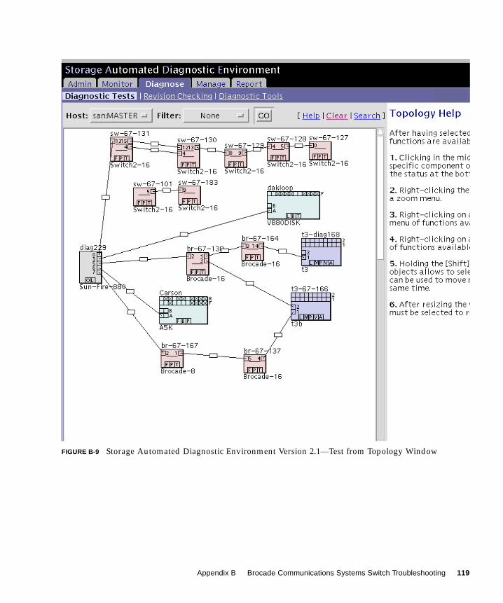
FIGURE B-9 Storage Automated Diagnostic Environment Version 2.1—Test from Topology Window
Appendix B Brocade Communications Systems Switch Troubleshooting 119

120 Sun StorEdge SAN 4.0 Release Field Troubleshooting Guide • October 2002
APPENDIX C
Brocade Communications SystemsError Messages
This appendix explains the error message format and possible errors and containsthe following topics:
■ “Error Message Formats” on page 122
■ “Diagnostic Error Message Formats” on page 123
121

Error Message FormatsThere are two error message formats depending on whether you are gatheringinformation from the front panel or via Telnet. The front panel shows an abbreviatedmessage and by way of Telnet displays the entire error message.
In all cases, the last error encountered is the first error displayed. Up to 32 messagesare held in a buffer. If the 32 message limit is exceeded, the messages are overwrittenin a first in, first out sequence.
Note – Error messages are stored in volatile RAM and are lost whenever power isremoved from the switch. Access the error message log to view error messagesbefore removing power.
Front Panel Message FormatsThe Brocade Silkworm switch’s front panel displays error messages. The first lineincludes the error’s date and time. The beginning of each second line on the frontpanel display starts with the module name, error name, and the severity level (1).
The possible values are:
■ 1—critical
■ 2—error
■ 3—warning
■ 4—informational
■ 5—debug
Note – If the same error occurs within the same module but on different ports, thenumber of occurrences for that message is incremented in brackets (up to 999), andthe error number is not incremented (that is, this error, though it may occur 999times, occupies one message in the 32-message buffer).
122 Sun StorEdge SAN 4.0 Release Field Troubleshooting Guide • October 2002

▼ To Display Error Messages from the Front Panel
1. From the front panel, select the Status menu.
2. Select Error Log.
3. Scroll through the error log. If no errors are encountered, the panel displaysNo Error.
Diagnostic Error Message FormatsIf any port fails during a diagnostic test, it is marked BAD in the status display.
To retest a port that has been marked BAD, clear the port and set to OK using thediagClearError (port#) command. This command clears the port status onlyand does not clear the logs or change the port’s condition. The diagClearError(port#) command should only be used during diagnostic procedures to reset a badport for retest.
Some messages contain the following abbreviations:
■ sb = Should Be
■ er = Bits in error
Note – If you run the portStateShow or the diagShow command prior torunning a test, errors may appear as a result of the normal synchronization process.These errors should be addressed if the number of errors found increases whenrunning the portStateShow command again.
TABLE C-1 Probable Failure Actions
Failed Test Action
ramTest replace DRAM module or mainboard assembly
portRegTest replace mainboard assembly
centralMemoryTest replace mainboard assembly
cmiTest replace mainboard assembly
cmemRetentionTest replace mainboard assembly
sramRetentionTest replace mainboard assembly
camTest replace mainboard assembly
Appendix C Brocade Communications Systems Error Messages 123

Error Message Numbers
An error number ERR#xxxx appears at the end of an error message. TABLE C-2matches each error number with the test that caused the error and the name of theerror. Look up the complete definition of the error name and the actions that willcorrect the error in TABLE C-3.
portLoopbackTest replace mainboard assembly
crossPortTest replace mainboard assembly, SFP, or fiber cable
spinSilk replace mainboard assembly, SFP, or fibre cable
TABLE C-2 Error Message Codes Defined
Error Number Test Name Error Name
0001 n/a DIAG-CLEAR_ERR
0004 n/a DIAG-POST_SKIPPED
0B15 sramRetentionTest DIAG-REGERR
0B16 DIAG-REGERR_UNRST
0B0F DIAG-BUS_TIMEOUT
1F25 cmemRetentionTest DIAG-LCMRS
1F26 DIAG-LCMTO
1F27 DIAG-LCMEM
0110 ramTest DIAG-MEMORY
0111 DIAG-MEMSZ
0112 DIAG-MEMNULL
0415 portRegTest DIAG-REGERR
0416 DIAG-REGERR_UNRST
040F DIAG-BUS_TIMEOUT
TABLE C-1 Probable Failure Actions (Continued)
Failed Test Action
124 Sun StorEdge SAN 4.0 Release Field Troubleshooting Guide • October 2002
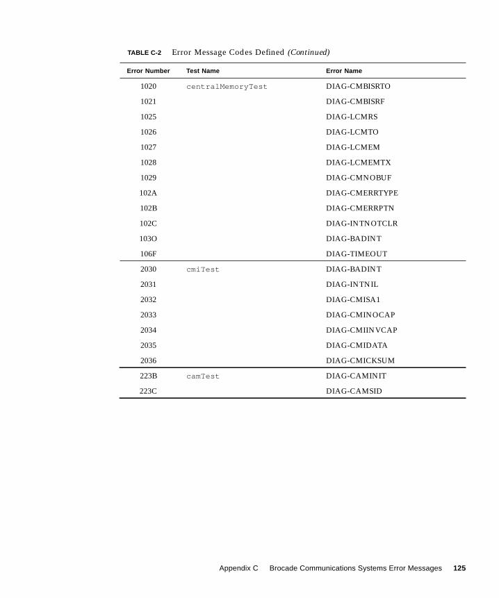
1020 centralMemoryTest DIAG-CMBISRTO
1021 DIAG-CMBISRF
1025 DIAG-LCMRS
1026 DIAG-LCMTO
1027 DIAG-LCMEM
1028 DIAG-LCMEMTX
1029 DIAG-CMNOBUF
102A DIAG-CMERRTYPE
102B DIAG-CMERRPTN
102C DIAG-INTNOTCLR
103O DIAG-BADINT
106F DIAG-TIMEOUT
2030 cmiTest DIAG-BADINT
2031 DIAG-INTNIL
2032 DIAG-CMISA1
2033 DIAG-CMINOCAP
2034 DIAG-CMIINVCAP
2035 DIAG-CMIDATA
2036 DIAG-CMICKSUM
223B camTest DIAG-CAMINIT
223C DIAG-CAMSID
TABLE C-2 Error Message Codes Defined (Continued)
Error Number Test Name Error Name
Appendix C Brocade Communications Systems Error Messages 125
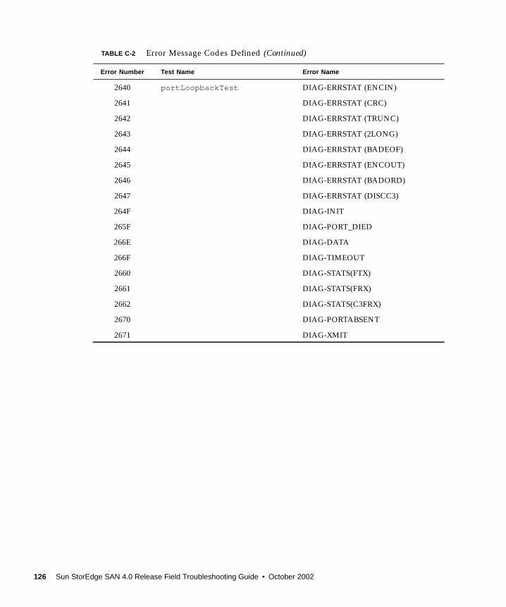
2640 portLoopbackTest DIAG-ERRSTAT (ENCIN)
2641 DIAG-ERRSTAT (CRC)
2642 DIAG-ERRSTAT (TRUNC)
2643 DIAG-ERRSTAT (2LONG)
2644 DIAG-ERRSTAT (BADEOF)
2645 DIAG-ERRSTAT (ENCOUT)
2646 DIAG-ERRSTAT (BADORD)
2647 DIAG-ERRSTAT (DISCC3)
264F DIAG-INIT
265F DIAG-PORT_DIED
266E DIAG-DATA
266F DIAG-TIMEOUT
2660 DIAG-STATS(FTX)
2661 DIAG-STATS(FRX)
2662 DIAG-STATS(C3FRX)
2670 DIAG-PORTABSENT
2671 DIAG-XMIT
TABLE C-2 Error Message Codes Defined (Continued)
Error Number Test Name Error Name
126 Sun StorEdge SAN 4.0 Release Field Troubleshooting Guide • October 2002
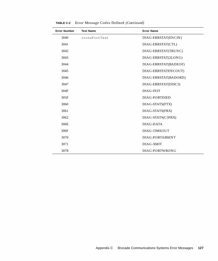
3040 crossPortTest DIAG-ERRSTAT(ENCIN)
3041 DIAG-ERRSTAT(CTL)
3042 DIAG-ERRSTAT(TRUNC)
3043 DIAG-ERRSTAT(2LONG)
3044 DIAG-ERRSTAT(BADEOF)
3045 DIAG-ERRSTATENCOUT)
3046 DIAG-ERRSTAT(BADORD)
3047 DIAG-ERRSTAT(DISC3)
304F DIAG-INIT
305F DIAG-PORTDIED
3060 DIAG-STATS(FTX)
3061 DIAG-STATS(FRX)
3062 DIAG-STATS(C3FRX)
306E DIAG-DATA
306F DIAG-TIMEOUT
3070 DIAG-PORTABSENT
3071 DIAG-XMIT
3078 DIAG-PORTWRONG
TABLE C-2 Error Message Codes Defined (Continued)
Error Number Test Name Error Name
Appendix C Brocade Communications Systems Error Messages 127
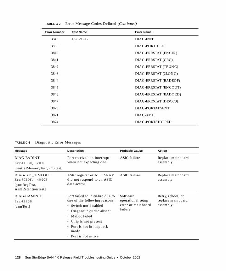
384F spinSilk DIAG-INIT
385F DIAG-PORTDIED
3840 DIAG-ERRSTAT (ENCIN)
3841 DIAG-ERRSTAT (CRC)
3842 DIAG-ERRSTAT (TRUNC)
3843 DIAG-ERRSTAT (2LONG)
3844 DIAG-ERRSTAT (BADEOF)
3845 DIAG-ERRSTAT (ENCOUT)
3846 DIAG-ERRSTAT (BADORD)
3847 DIAG-ERRSTAT (DISCC3)
3870 DIAG-PORTABSENT
3871 DIAG-XMIT
3874 DIAG-PORTSTOPPED
TABLE C-3 Diagnostic Error Messages
Message Description Probable Cause Action
DIAG-BADINTErr#1030, 2030
[centralMemoryTest, cmiTest]
Port received an interruptwhen not expecting one
ASIC failure Replace mainboardassembly
DIAG-BUS_TIMEOUTErr#0BOF, 4040F
[portRegTest,sramRetentionTest]
ASIC register or ASIC SRAMdid not respond to an ASICdata access
ASIC failure Replace mainboardassembly
DIAG-CAMINITErr#223B
[camTest]
Port failed to initialize due toone of the following reasons:• Switch not disabled• Diagnostic queue absent• Malloc failed• Chip is not present• Port is not in loopback
mode• Port is not active
Softwareoperational setuperror or mainboardfailure
Retry, reboot, orreplace mainboardassembly
TABLE C-2 Error Message Codes Defined (Continued)
Error Number Test Name Error Name
128 Sun StorEdge SAN 4.0 Release Field Troubleshooting Guide • October 2002
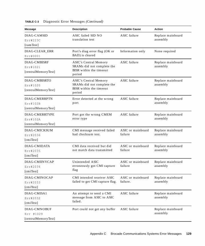
DIAG-CAMSIDErr#223C
[camTest]
ASIC failed SID NOtranslation test
ASIC failure Replace mainboardassembly
DIAG-CLEAR_ERRErr#0001
Port’s diag error flag (OK orBAD) is cleared
Information only None required
DIAG-CMBISRFErr#1021
[centralMemoryTest]
ASIC’s Central MemorySRAMs did not complete theBISR within the timeoutperiod
ASIC failure Replace mainboardassembly
DIAG-CMBISRTOErr#1020
[centralMemoryTest]
ASIC’s Central MemorySRAMs did not complete theBISR within the timeoutperiod
ASIC failure Replace mainboardassembly
DIAG-CMERRPTNErr#102B
[centralMemoryTest]
Error detected at the wrongport
ASIC failure Replace mainboardassembly
DIAG-CMERRTYPEErr#102A
[centralMemoryTest]
Port got the wrong CMEMerror type
ASIC failure Replace mainboardassembly
DIAG-CMICKSUMErr#2036
[cmiTest]
CMI message received failedbad checksum test.
ASIC or mainboardfailure
Replace mainboardassembly
DIAG-CMIDATAErr#2035
[cmiTest]
CMI data received but didnot match data transmitted
ASIC or mainboardfailure
Replace mainboardassembly
DIAG-CMIINVCAPErr#2034
[cmiTest]
Unintended ASICerroneously got CMI captureflag
ASIC or mainboardfailure
Replace mainboardassembly
DIAG-CMINOCAPErr#2033
[cmiTest]
CMI intended receiver ASICfailed to get CMI capture flag.
ASIC or mainboardfailure.
Replace mainboardassembly
DIAG-CMISA1Err#2032
[cmiTest]
An attempt to send a CMImessage from ASIC to ASICfailed.
ASIC failure Replace mainboardassembly
DIAG-CMNOBUFErr #1029
[centralMemoryTest]
Port could not get any buffer ASIC failure Replace mainboardassembly
TABLE C-3 Diagnostic Error Messages (Continued)
Message Description Probable Cause Action
Appendix C Brocade Communications Systems Error Messages 129
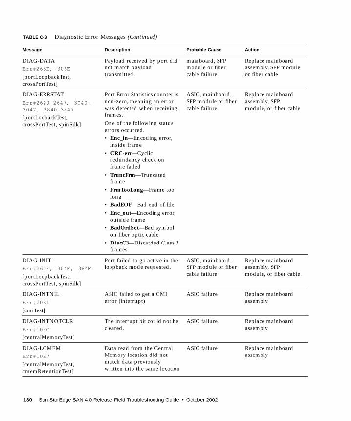
DIAG-DATAErr#266E, 306E
[portLoopbackTest,crossPortTest]
Payload received by port didnot match payloadtransmitted.
mainboard, SFPmodule or fibercable failure
Replace mainboardassembly, SFP moduleor fiber cable
DIAG-ERRSTATErr#2640-2647, 3040-3047, 3840-3847
[portLoobackTest,crossPortTest, spinSilk]
Port Error Statistics counter isnon-zero, meaning an errorwas detected when receivingframes.One of the following statuserrors occurred.• Enc_in—Encoding error,
inside frame• CRC-err—Cyclic
redundancy check onframe failed
• TruncFrm—Truncatedframe
• FrmTooLong—Frame toolong
• BadEOF—Bad end of file• Enc_out—Encoding error,
outside frame• BadOrdSet—Bad symbol
on fiber optic cable• DiscC3—Discarded Class 3
frames
ASIC, mainboard,SFP module or fibercable failure
Replace mainboardassembly, SFPmodule, or fiber cable
DIAG-INITErr#264F, 304F, 384F
[portLoopbackTest,crossPortTest, spinSilk]
Port failed to go active in theloopback mode requested.
ASIC, mainboard,SFP module or fibercable failure
Replace mainboardassembly, SFPmodule, or fiber cable.
DIAG-INTNILErr#2031
[cmiTest]
ASIC failed to get a CMIerror (interrupt)
ASIC failure Replace mainboardassembly
DIAG-INTNOTCLRErr#102C
[centralMemoryTest]
The interrupt bit could not becleared.
ASIC failure Replace mainboardassembly
DIAG-LCMEMErr#1027
[centralMemoryTest,cmemRetentionTest]
Data read from the CentralMemory location did notmatch data previouslywritten into the same location
ASIC failure Replace mainboardassembly
TABLE C-3 Diagnostic Error Messages (Continued)
Message Description Probable Cause Action
130 Sun StorEdge SAN 4.0 Release Field Troubleshooting Guide • October 2002

DIAG-LCMEMTXErr#1F27, 1028
[centralMemoryTest]
Central Memory transmitpath failure: ASIC 1 failed toread ASIC 2 via the transmitpath
mainboard failure Replace mainboardassembly
DIAG-LCMRSErr#1F25, 1025
[centralMemoryTestcmemRetentionTest]
Central Memory Read Short:M bytes requested but gotless than M bytes
ASIC failure Replace mainboardassembly
DIAG-LCMTOErr#1F267, 1026
[centralMemoryTest,cmemRetentionTest]
Central Memory Timeout:Data transfer initiated, didnot complete within thetimeout period.
ASIC failure Replace mainboardassembly
DIAG-MEMNULLErr#0112
[ramTest]
Test failed to malloc. mainboard failure Replace mainboardassembly
DIAG-MEMSZErr#0111
[ramTest]
Memory size to be tested isless than or equal to zero
mainboard failure Replace mainboardassembly
DIAG-MEMORYErr#0110
[ramTest]
Data read from RAM locationdid not match previously-written data into samelocation.
CPU RAM failure Replace mainboardassembly or DRAMmodule
DIAG-PORTABSENTErr#2670, 3070, 3870
[portLoopbackTest,crossPortTest, spinSilk]
Port is not present ASIC or mainboardfailure
Replace mainboardassembly
DIAG-PORTDIEDErr#265F, 305F, 385F
[portLoopbackTest,crossPortTest, spinSilk]
Port was in loopback modeand then went inactive
ASIC, SFP moduleor fiber cable failure
Replace mainboardassembly, SFPmodule, or fiber cable
DIAG-PORTSTOPPEDErr#3874
[spinSilk]
Port is no longertransmitting, as indicated bythe Number Of FramesTransmitted counter beingstuck at N frames.
ASIC, SFP module,or fiber cable failure.
Replace mainboardassembly, SFPmodule, or fiber cable.
DIAG-PORTWRONGErr#3078
[crossPortTest]
Frame erroneously receivedby port M instead of theintended port N
ASIC failure Replace mainboardassembly
TABLE C-3 Diagnostic Error Messages (Continued)
Message Description Probable Cause Action
Appendix C Brocade Communications Systems Error Messages 131
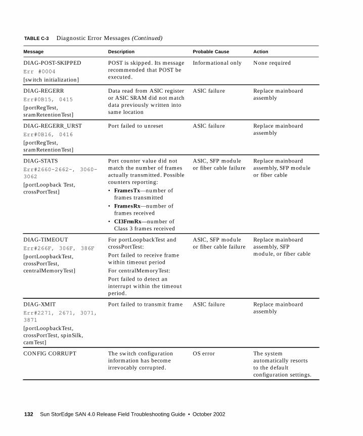
DIAG-POST-SKIPPEDErr #0004
[switch initialization]
POST is skipped. Its messagerecommended that POST beexecuted.
Informational only None required
DIAG-REGERRErr#0B15, 0415
[portRegTest,sramRetentionTest]
Data read from ASIC registeror ASIC SRAM did not matchdata previously written intosame location
ASIC failure Replace mainboardassembly
DIAG-REGERR_URSTErr#0B16, 0416
[portRegTest,sramRetentionTest]
Port failed to unreset ASIC failure Replace mainboardassembly
DIAG-STATSErr#2660-2662-, 3060-3062
[portLoopback Test,crossPortTest]
Port counter value did notmatch the number of framesactually transmitted. Possiblecounters reporting:• FramesTx—number of
frames transmitted• FramesRx—number of
frames received• CI3FrmRx—number of
Class 3 frames received
ASIC, SFP moduleor fiber cable failure
Replace mainboardassembly, SFP moduleor fiber cable
DIAG-TIMEOUTErr#266F, 306F, 386F
[portLoopbackTest,crossPortTest,centralMemoryTest]
For portLoopbackTest andcrossPortTest:Port failed to receive framewithin timeout periodFor centralMemoryTest:Port failed to detect aninterrupt within the timeoutperiod.
ASIC, SFP moduleor fiber cable failure
Replace mainboardassembly, SFPmodule, or fiber cable
DIAG-XMITErr#2271, 2671, 3071,3871
[portLoopbackTest,crossPortTest, spinSilk,camTest]
Port failed to transmit frame ASIC failure Replace mainboardassembly
CONFIG CORRUPT The switch configurationinformation has becomeirrevocably corrupted.
OS error The systemautomatically resortsto the defaultconfiguration settings.
TABLE C-3 Diagnostic Error Messages (Continued)
Message Description Probable Cause Action
132 Sun StorEdge SAN 4.0 Release Field Troubleshooting Guide • October 2002

CONFIG OVERFLOW The switch configurationinformation has grown toolarge to be saved or has aninvalid size.
OS error Contact customersupport
CONFIG VERSION The switch has encounteredan unrecognized version ofthe switch configuration.
OS error The systemautomatically resortsto the defaultconfiguration settings.
FABRIC, SEGMENTED,LOG_WARNING
Fabric segmented • Incompatiblefabric parametersand switches
• Conflict zones
Reconfigure fabric orzones
FABRIC, NO_ALIASID,LOG_WARNING
No free multicast alias Too many multicastgroups in use
Remove some of thegroups
FABRIC, BADILS,LOG_WARNING
Bad ISL-ELS size The ISL-ELSpayload is wrong
Contact customersupport
FLASH, BAD_MIRROR,LOG_WARNING
The system’s flash memoryhas encountered an error
OS error The system attemptsto recover from itsmirrored backup.Contact customersupport.
RPC, SVC_EXIT An RPC service daemon hasterminated prematurely orunexpectedly.
OS error Contact customersupport
RPC, SVC_REG An RPC service daemoncould not establish service fora particular protocol handler.
OS error Contact customersupport
TEMP, 1_FAILED,LOG_WARNING
Switch overheated Fan failure Contact customersupport
TEMP, 2_FAILED,LOG_ERROR
Switch overheated Fan failure Contact customersupport
TEMP, 3_FAILED,LOG_CRITICAL
Switch overheated Fan failure Contact customersupport
TEMP, 4_FAILED,LOG_CRITICAL
Switch overheated Fan failure Contact customersupport
TEMP, 5_FAILED,LOG_CRITICAL
Switch overheated Fan failure Contact customersupport
FANS, 1_FAILED,LOG_WARNING
Switch overheated Fan failure Contact customersupport
TABLE C-3 Diagnostic Error Messages (Continued)
Message Description Probable Cause Action
Appendix C Brocade Communications Systems Error Messages 133
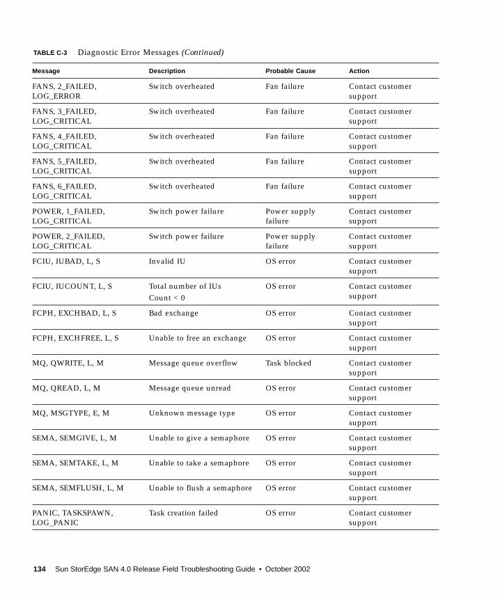
FANS, 2_FAILED,LOG_ERROR
Switch overheated Fan failure Contact customersupport
FANS, 3_FAILED,LOG_CRITICAL
Switch overheated Fan failure Contact customersupport
FANS, 4_FAILED,LOG_CRITICAL
Switch overheated Fan failure Contact customersupport
FANS, 5_FAILED,LOG_CRITICAL
Switch overheated Fan failure Contact customersupport
FANS, 6_FAILED,LOG_CRITICAL
Switch overheated Fan failure Contact customersupport
POWER, 1_FAILED,LOG_CRITICAL
Switch power failure Power supplyfailure
Contact customersupport
POWER, 2_FAILED,LOG_CRITICAL
Switch power failure Power supplyfailure
Contact customersupport
FCIU, IUBAD, L, S Invalid IU OS error Contact customersupport
FCIU, IUCOUNT, L, S Total number of IUsCount < 0
OS error Contact customersupport
FCPH, EXCHBAD, L, S Bad exchange OS error Contact customersupport
FCPH, EXCHFREE, L, S Unable to free an exchange OS error Contact customersupport
MQ, QWRITE, L, M Message queue overflow Task blocked Contact customersupport
MQ, QREAD, L, M Message queue unread OS error Contact customersupport
MQ, MSGTYPE, E, M Unknown message type OS error Contact customersupport
SEMA, SEMGIVE, L, M Unable to give a semaphore OS error Contact customersupport
SEMA, SEMTAKE, L, M Unable to take a semaphore OS error Contact customersupport
SEMA, SEMFLUSH, L, M Unable to flush a semaphore OS error Contact customersupport
PANIC, TASKSPAWN,LOG_PANIC
Task creation failed OS error Contact customersupport
TABLE C-3 Diagnostic Error Messages (Continued)
Message Description Probable Cause Action
134 Sun StorEdge SAN 4.0 Release Field Troubleshooting Guide • October 2002

PANIC, SEMCREATE,LOG_PANIC
Semaphore creation failed OS error Contact customersupport
PANIC, SEMDELETE,LOG_PANIC
Semaphore OS error Contact customersupport
PANIC, QCREATE,LOG_PANIC
Message queuer failed OS error Contact customersupport
PANIC, QDELETE,LOG_PANIC
Message queuer deletionfailed
OS error Contact customersupport
PANIC, MALLOC,LOG_PANIC
Memory allocation failed OS error Contact customersupport
PANIC, FREE, LOG_PANIC Memory free failed OS error Contact customersupport
PANIC, INCONSISTENT,LOG_PANIC
Data out of sync OS error Contact customersupport
PANIC, INTCONTEXT,LOG_PANIC
Data out of sync OS error Contact customersupport
PANIC, ZOMTIMSET,LOG_PANIC
Attempt to set a zombie timer OS error Contact customersupport
PANIC, ZOMTIMKILL,LOG_PANIC
Zombie timer destroyed OS error Contact customersupport
PANIC, FREETIMRLSD,LOG_PANIC
Free timer released OS error Contact customersupport
PANIC, TIMEUSECNT,LOG_PANIC
Timer use count exceeded OS error Contact customersupport
PANIC, LSDB_CKSUM,LOG_PANIC
Link State Databasechecksum failed
OS error Contact customersupport
SYS, NOMEM,LOG_CRITICAL
No memory OS error Contact customersupport
SYS, SYSCALL, LOG_ERROR System call failed OS error Contact customersupport
SYS, BADPTR, LOG_ERROR Bad system pointer OS error Contact customersupport
SYS, INTRPT,LOG_CRITICAL
Bad system interrupt OS error Contact customersupport
SYS, FLASHRD,LOG_ERROR
FLASH memory read error OS error Contact customersupport
TABLE C-3 Diagnostic Error Messages (Continued)
Message Description Probable Cause Action
Appendix C Brocade Communications Systems Error Messages 135

SYS, FLASHWR,LOG_ERROR
FLASH memory write error OS error Contact customersupport
TIMERS, ENQFAIL,LOG_CRITICAL
Invalid timeout value OS error Contact customersupport
TIMERS, MSG,LOG_WARNING
Invalid message OS error Contact customersupport
FLANNEL, PHANTOM,LOG_WARNING
Port’s PLT limit exceeded OS error Contact customersupport
ASIC, MINI_BUFFER,LOG_WARNING
ASIC Failure Bad mainboard Contact customersupport
LSDB, LSID, LOG_ERROR Link State ID’d out of range OS error Contact customersupport
LSDB, NOLOCALENTRY,LOG_CRITICAL
No database entry for locallink state record
OS error Contact customersupport
LSDB, NOLSR,LOG_WARNING
No link state record fordomain
OS error Contact customersupport
LSDB, MAXINCARN,LOG_WARNING
Local link state recordreached max incarnation
OS error Contact customersupport
FLOOD, INVLSU,LOG_WARNING
Discard received LSU OS error Contact customersupport
FLOOD, INVLSR,LOG_WARNING
Unknown LSR type OS error Contact customersupport
FLOOD, LSRLEN,LOG_ERROR
Excessive LSU length OS error Contact customersupport
HLO, INVHLO,LOG_ERROR
Invalid Hello received fromport
OS error Contact customersupport
HLO, HLOTIMEOUT,LOG_ERROR
Incompatible Hello timeoutfrom port
OS error Contact customersupport
HLO, DEADTIMEOUT,LOG_ERROR
Incompatible inactivitytimeout from port
OS error Contact customersupport
FSPF, SCN, LOG_WARNING Illegal SCN OS error Contact customersupport
FSPF, NBRCHANGE,LOG_WARNING
Wrong neighbor ID in Hellomessage from port
OS error Contact customersupport
FSPF, INPORT, LOG_ERROR Input port out of range OS error Contact customersupport
TABLE C-3 Diagnostic Error Messages (Continued)
Message Description Probable Cause Action
136 Sun StorEdge SAN 4.0 Release Field Troubleshooting Guide • October 2002

FSPF, VERSION,LOG_ERROR
FSPF version not supported OS error Contact customersupport
FSPF, SECTION,LOG_ERROR
Wrong section ID OS error Contact customersupport
FSPF, REMDOMAIN,LOG_ERROR
Remote Domain ID out ofrange
OS error Contact customersupport
NBFSM, NGBRSTATE,LOG_ERROR
Wrong input to neighbor FSM OS error Contact customersupport
MCAST, ADDPORT,LOG_WARNING
Add port failed OS error Contact customersupport
MCCAST, REMPORT,LOG_WARNING
Remove port failed OS error Contact customersupport
MCAST, ADDBRANCH,LOG_ERROR
Add branch failed OS error Contact customersupport
MCAST, REMBRANCH,LOG_ERROR
Remove branch failed OS error Contact customersupport
MCAST, NOPARENT,LOG_ERROR
Null parent OS error Contact customersupport
MCAST, NOPARENTLSR,LOG_ERROR
Null IsrP OS error Contact customersupport
UCAST, ADDPATH,LOG_CRITICAL
Add path failed OS error Contact customersupport
UCAST, ADDPORT,LOG_WARNING
Add port failed OS error Contact customersupport
UCAST, REMPORT,LOG_WARNING
Remove port failed OS error Contact customersupport
UCAST, RRTIM,LOG_CRITICAL
Invalid reroute timer ID OS error Contact customersupport
UCAST, SPFCOST,LOG_WARNING
No minimum cost path incandidate
OS error Contact customersupport
UCAST, RELICPDB,LOG_WARNING
Relic PDB to Domain OS error Contact customersupport
TABLE C-3 Diagnostic Error Messages (Continued)
Message Description Probable Cause Action
Appendix C Brocade Communications Systems Error Messages 137

138 Sun StorEdge SAN 4.0 Release Field Troubleshooting Guide • October 2002
APPENDIX D
Converting Sun FC Switches FibreChannel Addresses
This appendix explains how the Sun FC switch encodes Fibre Channel addresses.
Note – This information only applies to the Sun FC switches.
This appendix contains the following topics:
■ “Converting a Fabric Address into Fabric ID, Chassis ID, ASIC, Port, and AL_PA”on page 140
■ “Example” on page 141
139
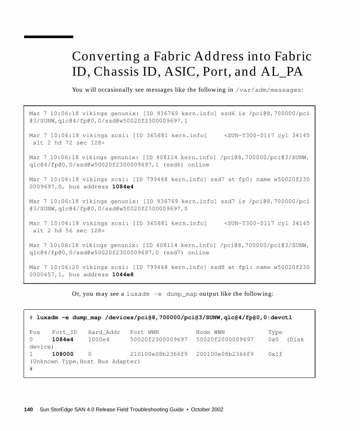
Converting a Fabric Address into FabricID, Chassis ID, ASIC, Port, and AL_PAYou will occasionally see messages like the following in /var/adm/messages:
Or, you may see a luxadm -e dump_map output like the following:
Mar 7 10:06:18 vikings genunix: [ID 936769 kern.info] ssd6 is /pci@8,700000/pci@3/SUNW,qlc@4/fp@0,0/ssd@w50020f2300009697,1
Mar 7 10:06:18 vikings scsi: [ID 365881 kern.info] <SUN-T300-0117 cyl 34145 alt 2 hd 72 sec 128>
Mar 7 10:06:18 vikings genunix: [ID 408114 kern.info] /pci@8,700000/pci@3/SUNW,qlc@4/fp@0,0/ssd@w50020f2300009697,1 (ssd6) online
Mar 7 10:06:18 vikings scsi: [ID 799468 kern.info] ssd7 at fp0: name w50020f2300009697,0, bus address 1084e4
Mar 7 10:06:18 vikings genunix: [ID 936769 kern.info] ssd7 is /pci@8,700000/pci@3/SUNW,qlc@4/fp@0,0/ssd@w50020f2300009697,0
Mar 7 10:06:18 vikings scsi: [ID 365881 kern.info] <SUN-T300-0117 cyl 34145 alt 2 hd 56 sec 128>
Mar 7 10:06:18 vikings genunix: [ID 408114 kern.info] /pci@8,700000/pci@3/SUNW,qlc@4/fp@0,0/ssd@w50020f2300009697,0 (ssd7) online
Mar 7 10:06:20 vikings scsi: [ID 799468 kern.info] ssd8 at fp1: name w50020f2300000457,1, bus address 1044e8
# luxadm -e dump_map /devices/pci@8,700000/pci@3/SUNW,qlc@4/fp@0,0:devctl
Pos Port_ID Hard_Addr Port WWN Node WWN Type0 1084e4 1000e4 50020f2300009697 50020f2000009697 0x0 (Diskdevice)1 108000 0 210100e08b2366f9 200100e08b2366f9 0x1f(Unknown Type,Host Bus Adapter)#
140 Sun StorEdge SAN 4.0 Release Field Troubleshooting Guide • October 2002

In both of these outputs, a Fibre Channel (FC) address appears (the six-digit number,1084e4 for example). The FC address potentially provides useful troubleshootinginformation. The key to this is knowing how the Sun FC switch encodes theaddresses.
For a Qlogic switch, the address must first be changed from Hex to a 24-bit binarynumber.
Example1084e4 translates into hexadecimal as 100001000010011100100. (The calculatorremoves the first 3 bits because they were zeros. The number is actually000100001000010011100100, which is the number used in this example).000100001000010011100100 is the 24-bit binary representation of 1084e4.
Qlogic encodes this number in the following way:
■ The AL_PA will be zero if the device is a full fabric device, otherwise, it will bethe AL_PA of the loop device.
■ StorEdge Network Fibre Channel Switches have 2 or 4 ASICS (2 on the 8portswitch, 4 on the 16port switch). These ASICs are numbered from 0-3.
■ Each ASIC has 4 ports, numbered 0-3.■ The numbering on the switch faceplate goes from 1-8 or 1-16.■ So, ASIC 0, port 0 is actually Port 1 if you were looking at the switch. ASIC 3, port
3 would be Port 16 if you were looking at the switch.
Bits 0-3 Fabric ID
Bits 4-9 Chassis ID
Bits 10-13 ASIC
Bits 14-15 Port
Bits 16-23 AL_PA
Appendix D Converting Sun FC Switches Fibre Channel Addresses 141

000100001000010011100100 is broken down as follows:
You can convert these back into usable numbers. Binary -> Decimal (except forAL_PA, change it to Hex)
From this information, you can conclude the following:
■ The Fabric ID of the switch is 1
■ The Chassis ID of the switch is 2
■ The port in question is port 0 of ASIC 1.
■ Port 0 of ASIC 1 is Port 5, if you were to look at the switch faceplate. (Refer toTABLE D-1 to see the ASIC/Port breakdown.)
■ The AL_PA of the device is E4.
Knowing this information, you can easily determine where this device is located inthe SAN. See TABLE D-1.
0001 Fabric ID
000010 Chassis ID
0001 ASIC ID
00 Port ID
11100100 AL_PA
Fabric ID 1
Chassis ID 2
ASIC ID 1
Port ID 0
AL_PA E4
TABLE D-1 ASIC and Port Values
Switch Port ASIC ID Port ID
1 0 0
2 0 1
3 0 2
4 0 3
142 Sun StorEdge SAN 4.0 Release Field Troubleshooting Guide • October 2002

5 1 0
6 1 1
7 1 2
8 1 3
9 2 0
10 2 1
11 2 2
12 2 3
13 3 0
14 3 1
15 3 2
16 3 3
TABLE D-1 ASIC and Port Values (Continued)
Appendix D Converting Sun FC Switches Fibre Channel Addresses 143

144 Sun StorEdge SAN 4.0 Release Field Troubleshooting Guide • October 2002
Acronyms & Glossary
This glossary contains definitions for terms used in this guide.
AcronymsAL_PA Arbitrated Loop Physical Address; 8-bit value used to identify a device.
E_Port An expansion or inter-switch port that can be connected to an E_Port ofanother switch to create a cascading interswitch link (ISL).
F_Port On a Fibre Channel switch, a port that supports an N_Port. A Fibre Channelport in a point-to-point or Fabric connection.
FL_Port On a Fibre Channel switch, a port that supports Arbitrated Loop devices.
G_Port A generic port that can automatically configure as either an E_Port or a F_Port
GL_Port A generic loop port can automatically configure as an E_Port, F_Port, or aFL_Port.
L_Port A loop port that enables private devices to communicate with fabric orpublic devices .
NAS Network Attached Storage
SNDR Sun StorEdge Network Data Replicator (formerly “Sun StorEdge RemoteDual Copy”)
TL_Port A Translated Loop Port on the Sun StorEdge T3 array that enables privatedevices to communicate with fabric or public devices.
U_Port A universal port that can operate as an E_Port, F_Port, or FL_Port.
145
GlossaryBroadcast Zone Zone type used to filter broadcast traffic away from end nodes that cannot use
or interpret it. A port will broadcast to all ports in the same Broadcast Zone(s)in which the port is defined. Broadcast zoning is primarily used for doing IPover Fibre Channel or when mixing IP and SCSI traffic on the switch. Thesezones are not yet useful or interesting in Suns current SAN implementations.
Cascade Connection of two or more switches together to increase the number ofavailable ports or to allow for increased distances between components of theSAN.
Fabric Fibre channel network built around one or more switches. It is also common torefer to something as a "Fabric device" or being in "Fabric mode". When usedin this context, it simply means a public device, capable of logging into aFabric and having public loop characteristics (as opposed to a private looplegacy device).
Hard Zones Hard Zones allow the division of the Fabric (one or more Switch chassis) intoas many as 16 Fabric-wide zones that define the ports that can communicatewith each other. A particular port may be placed in only one Hard Zone (nooverlapping Hard Zones). If Hard Zones are enabled, Name Server Zones andSL Zones will not communicate across defined Hard Zone boundaries.
Name Server Zones allow the division of the Fabric (one or more Switch chassis) into asmany as 256 Fabric-wide zones that define which ports or devices receiveName Server information. If Hard Zones are enabled, Name Server Zones willnot communicate across defined Hard Zone boundaries.
Private Loop An Arbitrated Loop without a Fabric switch
Public Loop An Arbitrated Loop attached to a Fabric switch.
Segmented Loop A set of ports that behave as one private loop.
Zone A set of ports and their connected devices (zone) that behave as a singleprivate loop. SL Zones on the switch allow the division of the Fabric (oneor more Switch chassis) into Fabric-wide zones that define the ports thatcan communicate with each other.
Zoning Zoning allows the user to divide the Fabric ports into zones for more efficientand secure communication among functionally grouped nodes. There areseveral types of zones and a port may be defined in any. No port can be in allzone types simultaneously.
146 Sun StorEdge SAN 4.0 Release Field Troubleshooting Guide • October 2002

Index
Aadapters, 6arrays
configuration guidelines, 22
Bbackward compatability, 5
Ccable, 4
LC-LC, 4SC-LC, 4SC-SC, 4
cascade limit, 3cascading rules, 23cluster support, 5configuration, 3
cascaded limit, 3disaster tolerant, 3high level using Network Storage Agent 2.1, 44multihost, 27single host connected to multiple storage
arrays, 25single host connected to one storage array, 24
configuration examples, 24configuration guidelines, 22configurations, 9conventions
typographic, xiicount
cascade limit, 3hop limit, 3ISL limit, 3ISL link limit, 3long-wave tranceiver limit, 3maximum switches, 3
Ddiagnostic tool
T3Extractor, 40disaster tolerant configuration, 3document
purpose, 1scope, 2
documentationaccessing online, xv
Ffabric, 4
division of, 21fabric support, 3fault isolation
examples of, 43setup requirements, 44switch to storage error, 47
FC-SW2, 4mode, 6
147

Fibre ChannelFibre Channel arbitrated loop, 4
firmware, 5
GG_port, 4GBICs, 4GL_port, 4
Hhard zones, 4HBAs
supported configurations, 15host
local attachment, 3host bus adapter, 6
Iinterconnections, 2interoperability, 4, 6InterSwitchLink (ISL), 10ISL
link limit, 3
LLC-LC cable, 4local
host attachment, 3storage attachment, 3
long-waveSFP, 3tranceiver, 3
loop port, 4
Mmaximum switch count, 3mesh configuration, 3
multipathingsupport, 5
Nname server
port-based zones, 4WWN-based zones, 4zoning, 4
nested zoning, 4network adapters, 6NS
zoning, 4
Ooperating environment
required Solaris release, 14overlapping zones, 4
Ppackages
supported, 16partial fabric support, 3patches
downloading using Sunsolve., 16supported, 16
port-based zones, 4ports
T (cascading), 7preface
using UNIX commands, xi
Rrelated documentation
AnswerBook, xiSolaris Handbook for Sun Peripherals, xi
rulesadding and removing devices, 23cascading, 23zoning, 22
148 Sun StorEdge SAN 4.0 Release Field Troubleshooting Guide • October 2002

SSC-LC cable, 4SC-SC cable, 4Segmented Loop
zoning, 4shell prompts, xiiSL
port, 4zoning, 4
Small Form Factor Pluggable tranceivers, 4software, unbundled
supported, 17storage device
attachment, 3storage devices supported, 6StorEdge Traffic Manager tool, 5Sun StorEdge T3+ arrays, 6SunCluster 3.0, 5supported configurations, 3switch
configuration guidelines, 22connection of, 10management tools, 5
switch countersrole in troubleshooting, 41rules when viewing, 41
switch port types, 19
Tthird-party
compatability, 6switch capability, 6
TLport, 4
toolsdiagnostic, 31
topologies supported, 3tranceivers, 3translative
loop, 4troubleshooting
steps to use to approach a SAN problem, 45
UUNIX commands
use of, xi
VVERITAS Cluster Server, 5
Wwebsites
for additional information, 2WWN-based zones, 4
Zzone
name server, 21zones
configuration guidelines, 22definition of, 21
zoning, 4zoning rules, 22
Index 149

150 Sun StorEdge SAN 4.0 Release Field Troubleshooting Guide • October 2002