sunrail™ nautilus installation instructions table of …„¢ nautilus installation instructions...
TRANSCRIPT

SunRail™ Nautilus Installation InstructionsThe SunRail Nautilus System combines the modern look of stainless steel cable and tensioners with the low maintenance quality of highly polished or brushed tubing.
The following guide will take you step-by-step through the process of installing your SunRail Nautilus System. Along the way, we’ll offer you tips and tricks to help you get your railing installed today and ready for tomorrow.
2018 All Rights Reserved ▪ Atlantis Rail Systems, SunRail and RailEasy is a registered trademark and trademark of Suncor Stainless, Inc. ▪ Loctite is a registered trademark of Henkel Corporation ▪ www.atlantisrail.com
1 May 2018
ATLANTIS RAIL Contact Information:
Atlantis Rail Systems70 Armstrong Road 3900 Civic Center DrivePlymouth, MA 02360 North Las Vegas, NV 89030
(800) 541-6829 or (508) 732-9191 (508) 732-9798 www.atlantisrail.com
Tools
Table of Contents
Warning Note Recommendation
Tools 1Tips for a Successful Installation 2RailEasy Components 2
Additional Components 2Preparation 3Straight Section - Installing the Posts 3Straight Section - Installing the Rails 4Straight Section - Installing the Cable 5Straight Section - Tensioning the Cable 6Stair & Ramp Section - Installing the Posts 7Stair & Ramp Section - Installing the Rails 7Stair & Ramp Section - Installing the Cable 8Stair & Ramp Section - Tensioning the Cable 9Additional Components 10SunRail Nautilus System Specifications 11SunRail Nautilus System Product Specifications 12
Required & Recommended
Power Drill 1/4” Drill Bit(for bases)
25’ Tape Measure 5.5 mm Allen Wrench
3/8”, 5/16 & 7/16” Open Wrenches
Carpenter’s Square
Chalk Line
Level
Loctite® 326 Gloves Safety Glasses
Cable Cutters #4 PhillipsDriver Bit
Ratchet Buckle

ALWAYS REFER TO YOUR LOCAL BUILDING CODE OFFICIALS PRIOR TO INSTALLING ANY ATLANTIS RAIL SYSTEM TO ENSURE ALL CODE AND SAFETY REQUIREMENTS ARE MET. ATLANTIS RAIL SYSTEMS IS NOT RESPONSIBLE FOR IMPROPER OR NON-RECOMMENDED INSTALLATIONS.
RailEasy Components
RailEasy Tensioner Round 5/32”S0982-0004
RailEasy Swivel End Round 5/32”S0982-S004
2018 All Rights Reserved ▪ Atlantis Rail Systems, SunRail and RailEasy is a registered trademark and trademark of Suncor Stainless, Inc. ▪ Loctite is a registered trademark of Henkel Corporation ▪ www.atlantisrail.com
2 May 2018
ATLANTIS RAIL SYSTEMS PROVIDES A VARIETY OF MOUNTING OPTIONS FOR POSTS AND RAILS USED IN OUR SYSTEMS. PRODUCTS OF THIS NATURE REQUIRE THAT MOUNTING SURFACES ARE CONSTRUCTED TO BE CONSIDERED STRUCTURAL PER BUILDING CODE DEFINITION FOR THE SURFACE MATERIAL USED. STRUCTURAL INTEGRITY AND BUILDING CODE COMPLIANCE OF MOUNTING SURFACES ARE THE RESPONSIBILITY OF THE END USER AND / OR INSTALLER. THE USE OF ANY OF OUR MOUNTING METHODS ARE AT THE OPTION AND DECISION OF THE END USER AND / OR INSTALLER AND SHOULD BE SELECTED TO MATCH THE STRUCTURAL MATERIAL USED TO CREATE THE MOUNTING SURFACE.
Tips for a Successful Installation
● Read the instructions completely before beginning the installation.
● Plan your railing project. Sketch your project with the actual measurements of your deck or balcony complete with post locations.
● Check carton(s) to determine part count is complete.● Installation is best accomplished with two (2) people.● Always wear personal protection equipment; safety glasses,
work gloves, etc.● Use care not to over-torque the screws. Pre-drilling is
recommended.
Additional Components
Concrete Mounting Base
* Micro Star LED lights can be integrated into the top rail for sublet illumination.
Fascia Mount Bracket Micro Star LED Light*Micro Star™ TransformersStabilizer and SunRail Cable Grommets

2018 All Rights Reserved ▪ Atlantis Rail Systems, SunRail and RailEasy is a registered trademark and trademark of Suncor Stainless, Inc. ▪ Loctite is a registered trademark of Henkel Corporation ▪ www.atlantisrail.com
3 May 2018
Figure A. Measure to the center of your structure or blocking and snap a chalk line to mark the centers. Do this around the perimeter of the deck.
SunRail PostsThe SunRail standard post kits contain the post and mounting base. Fasteners to mount the base to the decking surface are sold separately. Speak with your Atlantis Rail Sales Representative about the various mounting options. The following section will show you how to install the posts on straight sections of your deck.
Measure & Mark the CenterlinesUse a tape measure to find the centerline of your railing system. Measure from the edge of the deck to the center of the structure or blocking below (See Figure A). This is typically 3-1/2”. It is important that all the fasteners are secured to the structure or appropriate blocking. With the centerline measured, carefully snap a chalk line around the perimeter of the deck. This will be your centerline throughout the project. Make sure that the center of all of your bases fall along this line.
Install the Post BasesBegin with the end posts and corner posts. Place the base along the centerline being careful to make sure the base is properly oriented. Using the base as a template (See Figure B) , mark the 4 holes for the screws. Use a 1/4” drill bit to drill a pilot hole for the base screws. It is important to drill a proper pilot hole as this will help prevent the base screws from stripping. Use a #4 screwdriver or driver bit to fasten the base to the deck (See Figure C). Simply slide the end and corner posts onto the base. Check for level.
Straight Section - Installing the Posts
Preparation
Reading & Understanding Your Assembly DrawingYour assembly drawing is laid out numerically from the left of your drawing beginning with rail section one. For two rail systems, each rail section will have two rails, an upper hand rail (labeled UH) and a lower hand rail (labeled LH). Your railing system will be packaged in the same numeric fashion that it is labeled on your assembly drawing. This is so you can lay your boxes out according to which rail goes to which section.
Locate & Check the Parts of Your Rail SystemWhen your rail system arrives on site, take the time to make sure that all the parts you were supposed to receive are present and undamaged. Report any inconsistencies with your building products supplier or Atlantis Rail Sales Representa-tive as soon as you are aware of the issue.
Lay out your rails and posts on the appropriate deck. Open the boxes of fittings and lay the appropriate fittings out along with the rails. When all the parts are laid out and accounted for, you are ready to begin.
Figure B. (LEFT) Using the base as a template, mark the 4 holes for the screws.Figure C. (RIGHT) Fasten each base to the deck with four (4) 5/16” x 3” lag screws.
IF USING FASCIA MOUNT BRACKETS (S0950-0002) OR CONCRETE BASES (S0950-0006), PLEASE REFER TO SEPARATE INSTALLATION INSTRUCTIONS INCLUDED IN YOUR PACKET.
WHEN READING YOUR ASSEMBLY DRAWING, ALWAYS REMEMBER THE TOP RAIL IN THE PROJECTION VIEW IS ALWAYS FACING THE PLAN VIEW.
2018 All Rights Reserved ▪ Atlantis Rail Systems, SunRail and RailEasy is a registered trademark and trademark of Suncor Stainless, Inc. ▪ Loctite is a registered trademark of Henkel Corporation ▪ www.atlantisrail.com
4 May 2018
Straight Section - Installing the Rails
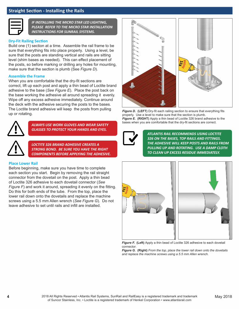
Dry-Fit Railing SectionBuild one (1) section at a time. Assemble the rail frame to be sure that everything fits into place properly. Using a level, be sure that the posts are standing vertical and rails are sitting level (shim bases as needed). This can effect placement of the posts, so before marking or drilling any holes for mounting, make sure that the section is plumb (See Figure D).
Assemble the FrameWhen you are comfortable that the dry-fit sections are correct, lift up each post and apply a thin bead of Loctite brand adhesive to the base (See Figure E). Place the post back on the base working the adhesive all around spreading it evenly. Wipe off any excess adhesive immediately. Continue around the deck with the adhesive securing the posts to the bases. The Loctite brand adhesive will keep the posts from pulling up or rotating.
Figure D. (LEFT) Dry-fit each railing section to ensure that everything fits properly. Use a level to make sure that the section is plumb.Figure E. (RIGHT) Apply a thin bead of Loctite 326 brand adhesive to the bases when you are comfortable that the dry-fit sections are correct.
ATLANTIS RAIL RECOMMENDS USING LOCTITE 326 ON THE BASES, TOP RAILS AND FITTINGS. THE ADHESIVE WILL KEEP POSTS AND RAILS FROM PULLING UP AND ROTATING. USE A DAMP CLOTH TO CLEAN UP EXCESS RESIDUE IMMEDIATELY.
IF INSTALLING THE MICRO STAR LED LIGHTING, PLEASE REFER TO THE MICRO STAR INSTALLATION INSTRUCTIONS FOR SUNRAIL SYSTEMS.
LOCTITE 326 BRAND ADHESIVE CREATES A STRONG BOND. BE SURE YOU HAVE THE RIGHT COMPONENTS BEFORE APPLYING THE ADHESIVE.
ALWAYS USE WORK GLOVES AND WEAR SAFETY GLASSES TO PROTECT YOUR HANDS AND EYES.
Place Lower RailBefore beginning, make sure you have time to complete each section you start. Begin by removing the rail straight connector from the dovetail on the post. Apply a thin bead of Loctite 326 adhesive to each dovetail connector (See Figure F) and work it around, spreading it evenly on the fitting. Do this for both ends of the tube. From the top, place the lower rail down onto the dovetails and replace the machine screws using a 5.5 mm Allen wrench (See Figure G). Do not leave adhesive to set until rails and infill are installed.
Figure F. (Left) Apply a thin bead of Loctite 326 adhesive to each dovetail connector.Figure G. (Right) From the top, place the lower rail down onto the dovetails and replace the machine screws using a 5.5 mm Allen wrench.

Figure L. Cutaway view of the RailEasy Tensioner
2018 All Rights Reserved ▪ Atlantis Rail Systems, SunRail and RailEasy is a registered trademark and trademark of Suncor Stainless, Inc. ▪ Loctite is a registered trademark of Henkel Corporation ▪ www.atlantisrail.com
5 May 2018
Install the Top RailPlace top rail into the posts (See Figure H). Slowly lift the elbows from the post enough to apply a small amount of adhesive. Do the same for either end of the top rail. Compress the top and bottom rails together using a ratchet buckle to ensure the proper fit. Leave assembled for adhesive to set.
RailEasy Round Tensioner & Swivel End Installation RailEasy Round Tensioners (C0982-0004)The tensioner (See Figure I) is the primary cable railing tensioning/fastening device. The compression fitting allows for installation and tensioning with simple hand tools. Also, it has a slotted base to achieve angles up to 45 degrees.
RailEasy Round Swivel Ends (C0982-S004)The swivel end (See Figure J) is used for cable railing applications. This swivel end is used in conjunction with a RailEasy Tensioner in order to tension cable. Also, it has a slotted base to achieve angles up to 45 degrees.
Figure H. Place top rail into the posts.
Figure I. Tensioners are riveted to each post at the factory and ready for installation.
Figure J. Swivel ends are riveted to each post at the factory and ready for installation.
Straight Section - Installing the Cable
Atlantis Rail offers cable cutters (C0989-00HD) to aid in the cutting of 5/32” cable. It is important that you use sharp tools to cut the cable, as a dull tool will splay it. Ask your Atlantis Rail Sales Representative for more information.
ALWAYS USE WORK GLOVES AND WEAR SAFETY GLASSES TO PROTECT YOUR HANDS AND EYES WHILE WORKING WITH CABLE. DO NOT OVER-TENSION.
RailEasy Tensioner (C0982-0004) Measure & Run the CableWith the tensioners installed (See Figure K), begin by extending the threaded stud outward a minimum of 3/4” for the first 20 feet plus 1/4” for each additional 10 feet. Insert the cable into the receiver cone, push and twist the cable opposite the lay of the wire strands. The cable should slide into the receiver cone until approximately 3/16” past the bottom of the wedge (See Figure L). Fully tighten the receiver cone onto the threaded stud using 7/16” and 3/8”
Figure K. Exploded view of the RailEasy Tensioner for easy identification of each component.
1 2 3 4 5 6 7
Patented Base Detail
Each base is slotted to achieve angles up to 45 degrees on stair and angled rails.
Curved base also available.
RailEasy™ Tensioner Components
1. Patented Base 5. Spacer2. Tensioner Body 6. Wedge3. Lock Nut 7. Receiver Cone4. Threaded Stud

2018 All Rights Reserved ▪ Atlantis Rail Systems, SunRail and RailEasy is a registered trademark and trademark of Suncor Stainless, Inc. ▪ Loctite is a registered trademark of Henkel Corporation ▪ www.atlantisrail.com
6 May 2018
Figure O. Tensioning Diagram - Begin with the center run of cable andalternate working above and below until cables are tight.
10864213579
Figure M. Cut the cable at the hex flats on the threaded stud.
Cut Cable Here
Cut Cable Here
Figure N. Cut the cable at the hex flats on the threaded stud.
open wrenches. Upon doing this, the wedge will crimp down on the cable and hold it in place. With the cable installed in one tensioner, pull the cable to the opposite tensioner. Pull the cable tight to the tensioner and cut it (See Figure M). Using the first run as a guide, cut the remaining runs to the same length. This will ensure uniformity among the tension-ers. Thread the cable through each mid post and install the cable into the opposite tensioner using the same process as before.
RailEasy Swivel End (C0982-S004) The swivel end must be used in conjunction with a RailEasy Tensioner in order to tension the cable. Follow the same process as above to install and cut the cable (See Figure N).
Straight Section - Tensioning the Cable
BEFORE TENSIONING ANY OF THE CABLES, IT IS IMPORTANT TO BE SURE THAT THE FRAME FOR THE INFILL IS COMPLETED.
Make sure the posts are installed securely and in accordance with the manufacturers’ recommended installation procedures. Install all top and intermediate rails. The posts will deflect beyond allowable limits if you attempt to tension the cables on an incomplete guard frame.
RailEasy Tensioner (C0982-0004)Tension the Center CableBefore tensioning with tools, hold the threaded stud firm and rotate the tensioner body by hand until all cables are snug.
Beginning with the center run of cable, hold the threaded stud firm using a 3/8” wrench. Using a 5/16” open wrench, rotate the tensioner body to tension the cable. Turn the body three or four full rotations until cable is snug. Don’t worry if this cable moves a little, we will come back around to it later. Tension cable equally from both ends of each cable span. Tighten Lock Nut to secure tension. Tension the Remaining CablesAlternate tensioning the cables from center, working above and below the center cable as if tightening the lug nuts on a tire (See Figure O). Rotate the body three or four full rotations or until cable is snug. You will notice as you tension, the cables surrounding it will slacken. When this begins happening, stop tensioning and move onto the next cable.
Make Final AdjustmentsGo back to the center cable and re-tighten the cables until all are tight and relatively equal in tension. You may find that you need to do this three or four times getting down to even a quarter turn of the tensioner body each time. Tension from

2018 All Rights Reserved ▪ Atlantis Rail Systems, SunRail and RailEasy is a registered trademark and trademark of Suncor Stainless, Inc. ▪ Loctite is a registered trademark of Henkel Corporation ▪ www.atlantisrail.com
7 May 2018
Stair & Ramp Section - Installing the Posts
The following section will show you how to install the posts on stairs and ramps of your deck.
Install the Post BasesDepending on the configuration of the stairs install either the Rail Mounting Base (S0950-0001 - See Figure P) or the Rail Adjustable Base (S0950-0003 - See Figure Q). Use a 1/4” drill bit to drill a pilot hole for the base screws. It is important to drill a proper pilot hole as this will help prevent the base screws from stripping. Use a #4 screwdriver or driver bit to fasten the base to the deck. Simply slide the end and corner posts onto the base. Check for level.
Figure P. (Left) Rail Mounting Base installed to a flat surface.Figure Q (Right) Angle Adjustable Base installed to an angled surface.
IF USING FASCIA MOUNT BRACKETS (S0950-0002) OR CONCRETE MOUNTING BASES (S0950-0006), PLEASE REFER TO SEPARATE INSTALLATION INSTRUCTIONS INCLUDED IN YOUR PACKET.
Stair & Ramp Section - Installing the Rails
Figure R. Begin dry-fitting the stair sections.
Dry Fit the FrameBeginning with any posts you have installed for the stair and ramp sections, begin dry-fitting the stair sections (See Figure R). This again is to ensure that all components of the railing will fit together properly without forcing. Locate the center of the bases. You will find the dimensions to the center of the bases on your drawing. Use these dimensions for the initial fit. Adjust as necessary continually checking for plumb. If the drawing is followed correctly, the top handrail will be parallel with the slope of the stairs and between 34”-38” in height (measured vertically directly above the nosing of the stair).
Assemble the FrameWhen you are comfortable that the dry-fit sections are correct, lift up each post and apply a thin bead of Loctite brand
both sides when necessary. Add “Non-Acidic” Silicone Sealant to open tip of Receiver Cone in harsh environments.
RailEasy Swivel End (C0982-S004) If using a swivel end, the opposite end of the cable assembly requires a RailEasy tensioning device. The swivel end should be installed in the post and have cable installed in it. Follow the tensioning directions for RailEasy Tensioner to tension the other side of the swivel end cable run.Clean and Wipe RailingsFinish by wiping down railings with warm water and a clean rag. It is a good idea to apply a protective coat of finishing compound. Atlantis Rail offers cleaning kits and rail care products. Ask your sales rep for more information.
IF INSTALLING THE MICRO STAR LED LIGHTING, PLEASE REFER TO THE MICRO STAR INSTALLATION INSTRUCTIONS FOR SUNRAIL SYSTEMS.
Place Lower RailBefore beginning, make sure you have time to complete each section you start. Begin by removing the Rail Adjustable Joint on the post. Apply a thin bead of Loctite 326 adhesive to connector (See Figure T) and work it around, spreading it evenly on the fitting. Do this for both ends of the tube. From the top, place the lower rail down onto the dovetails and replace the machine screws using a 5.5 mm Allen wrench (See Figure U). Do not leave adhesive to set until rails and infill are installed.Install Top RailPut the appropriate adjustable fittings on the top rail and rotate downward (See Figure V). Apply adhesive to these connections. Apply adhesive to the top rail and work it around evenly. Compress the top and bottom rails together using a ratchet buckle to ensure the proper fit. Leave assembled for adhesive to cure.
Figure V. Put the appropriate fittings on the top rail and rotate downward.
Stair & Ramp Section - Installing the Cable
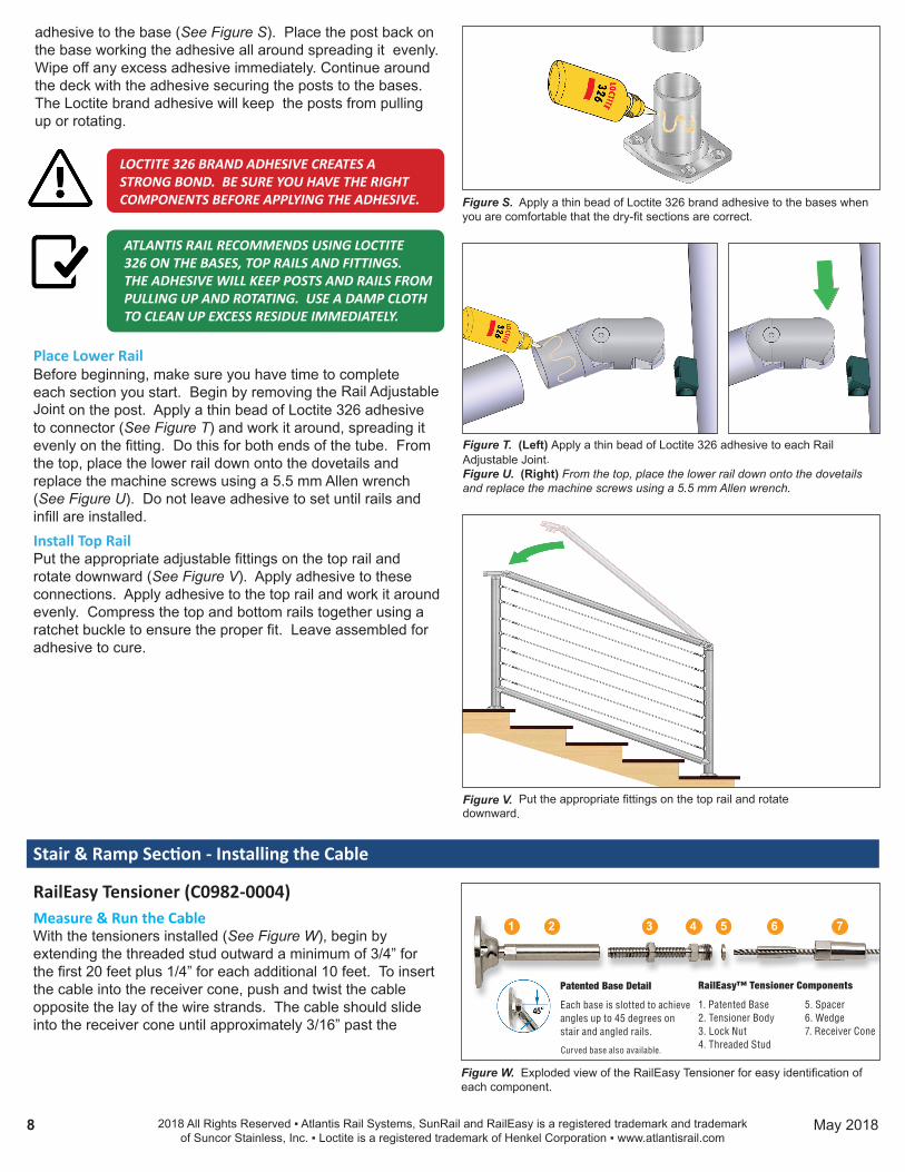
RailEasy Tensioner (C0982-0004) Measure & Run the CableWith the tensioners installed (See Figure W), begin by extending the threaded stud outward a minimum of 3/4” for the first 20 feet plus 1/4” for each additional 10 feet. To insert the cable into the receiver cone, push and twist the cable opposite the lay of the wire strands. The cable should slide into the receiver cone until approximately 3/16” past the
2018 All Rights Reserved ▪ Atlantis Rail Systems, SunRail and RailEasy is a registered trademark and trademark of Suncor Stainless, Inc. ▪ Loctite is a registered trademark of Henkel Corporation ▪ www.atlantisrail.com
8 May 2018
Figure T. (Left) Apply a thin bead of Loctite 326 adhesive to each Rail Adjustable Joint.Figure U. (Right) From the top, place the lower rail down onto the dovetails and replace the machine screws using a 5.5 mm Allen wrench.
Figure S. Apply a thin bead of Loctite 326 brand adhesive to the bases when you are comfortable that the dry-fit sections are correct.
adhesive to the base (See Figure S). Place the post back on the base working the adhesive all around spreading it evenly. Wipe off any excess adhesive immediately. Continue around the deck with the adhesive securing the posts to the bases. The Loctite brand adhesive will keep the posts from pulling up or rotating.
ATLANTIS RAIL RECOMMENDS USING LOCTITE 326 ON THE BASES, TOP RAILS AND FITTINGS. THE ADHESIVE WILL KEEP POSTS AND RAILS FROM PULLING UP AND ROTATING. USE A DAMP CLOTH TO CLEAN UP EXCESS RESIDUE IMMEDIATELY.
LOCTITE 326 BRAND ADHESIVE CREATES A STRONG BOND. BE SURE YOU HAVE THE RIGHT COMPONENTS BEFORE APPLYING THE ADHESIVE.
Figure W. Exploded view of the RailEasy Tensioner for easy identification of each component.
1 2 3 4 5 6 7
Patented Base Detail
Each base is slotted to achieve angles up to 45 degrees on stair and angled rails.
Curved base also available.
RailEasy™ Tensioner Components
1. Patented Base 5. Spacer2. Tensioner Body 6. Wedge3. Lock Nut 7. Receiver Cone4. Threaded Stud

Figure Y. Cut the cable at the hex flats on the threaded stud.
Cut Cable Here
bottom of the wedge (See Figure X). Fully tighten the receiver cone onto the threaded stud using 7/16” and 3/8” open wrenches. Upon doing this, the wedge will crimp down on the cable and hold it in place. With the cable installed in one tensioner, pull the cable to the opposite tensioner. Pullthe cable tight to the tensioner and cut it (See Figure Y). Using the first run as a guide, cut the remaining runs to the same length. This will ensure uniformity among the tensioners. Thread the cable through each mid post and install the cable into the opposite tensioner using the same process as before.
RailEasy Swivel End (C0982-S004) The swivel end must be used in conjunction with a RailEasy Tensioner in order to tension cable. Follow the same process as above to cut and install the cable (See Figure Z).
Figure Z. Cut the cable at the hex flats on the threaded stud.
Cut Cable Here
BEFORE TENSIONING ANY OF THE CABLES, IT IS IMPORTANT TO BE SURE THAT THE FRAME FOR THE INFILL IS COMPLETED.
Stair & Ramp Section - Tensioning the Cable
Make sure the posts are installed securely and in accordance with the manufacturers’ recommended installation procedures. Install all top and intermediate rails. The posts will deflect beyond allowable limits if you attempt to tension the cables on an incomplete guard frame.
RailEasy Tensioner (C0982-0004)Tension the Center CableBefore tensioning with tools, hold the threaded stud firm and rotate the tensioner body by hand until all cables are snug.
Beginning with the center run of cable, hold the threaded stud firm using a 3/8” wrench. Using a 5/16” open wrench, rotate the tensioner body to tension the cable (See Figure AA). Turn the body three or four full rotations until cable is snug. Don’t worry if this cable moves a little, we will come back around to it later. Tension cable equally from both ends of each cable span. Tighten Lock Nut to secure tension.
Figure AA. Hold the tensioner terminal still with a 3/8” wrench and using a 5/16” open wrench, rotate tensioner body to tension.
2018 All Rights Reserved ▪ Atlantis Rail Systems, SunRail and RailEasy is a registered trademark and trademark of Suncor Stainless, Inc. ▪ Loctite is a registered trademark of Henkel Corporation ▪ www.atlantisrail.com
9 May 2018
ALWAYS USE WORK GLOVES AND WEAR SAFETY GLASSES TO PROTECT YOUR HANDS AND EYES WHILE WORKING WITH CABLE. DO NOT OVER-TENSION.
Figure X. Cutaway view of the RailEasy Tensioner

Tension the Remaining CablesAlternate tensioning the cables from center, working above and below the center cable as if tightening the lug nuts on a tire (See Figure AB). Rotate the body three or four full rotations or until cable is snug. You will notice as you tension, the cables surrounding it will slacken. When this begins hap-pening, stop tensioning and move onto the next cable.
Make Final AdjustmentsGo back to the center cable and re-tighten the cables until all are tight and relatively equal in tension. You may find that you need to do this three or four times getting down to even a quarter turn of the tensioner body each time. Tension from both sides when necessary. Add “Non-Acidic” Silicone Sealant to open tip of Receiver Cone in harsh environments.
RailEasy Swivel End (C0982-S004) If using a swivel end, the opposite end of the cable assembly requires a RailEasy tensioning device. The swivel end should be installed in the post and have cable installed in it. Follow the tensioning directions for RailEasy Tensioner to tension the other side of the swivel end cable run.Clean and Wipe RailingsFinish by wiping down railings with warm water and a clean rag. It is a good idea to apply a protective coat of finishing compound. Atlantis Rail offers cleaning kits and rail care products. Ask your sales rep for more information.
Figure AB. Tensioning Diagram - Begin with the center run of cable andalternate working above and below until cables are tight.
1
2
4
6
3
5
7
Additional Components
Stabilizer and SunRail Cable Grommets - (C0196-0004-25)Once the cable has been installed and tensioned, it is time to add the cable grommets (part # C0196-0004-25). These grommets are slotted for easy attachment onto the cable. Snap the grommet onto the cable (See Figure AC). Slide it into the mid post hole (cable already installed) until it snaps into place and sits snug (See Figure AD). Available in packs of 25.
Concrete Mounting Base - S0950-0006Atlantis Rail offers a Concrete Mounting Base option when installing a SunRail system with stainless steel posts on a concrete surface. A single concrete anchor bolt (not supplied) is used to secure the mount (part # S0950-0006).
The Concrete Mounting Base (See Figure AE) matches the profile of the Atlantis Rail Mounting Base (S0950-0001) and Adjustable Base (S0950-0003). Use four (4) 5/16” x 3/4” stainless steel machine screws to attach the mounting base to the Concrete Mounting Base. For more detailed information please refer to the SunRail Concrete Mounting Base Installation Instructions.
Fascia Mount Bracket - S0950-0002Atlantis Rail offers a fascia mounting option when installing a SunRail system with stainless steel posts (part # S0950-0002). This bracket is designed to be combined with the Atlantis Rail Mounting Base or Adjustable Base. It is used when a fascia mounting system is desired.
There are two methods for fastening the Fascia Mount Bracket. You can use four (4) 1/2” lag bolts. These screw
Figure AC. (LEFT) Place the slotted side on the cable and push down.Figure AD. (RIGHT) Push the tapered end into the mid post hole.
Figure AE. Concrete Mounting Base (S0950-0006).
2018 All Rights Reserved ▪ Atlantis Rail Systems, SunRail and RailEasy is a registered trademark and trademark of Suncor Stainless, Inc. ▪ Loctite is a registered trademark of Henkel Corporation ▪ www.atlantisrail.com
10 May 2018
The SunRail Nautilus System combines the modern look of stainless steel cable railing with our polished or brushed stainless steel rails. Our patented RailEasy Tensioners are attached to each post at the factory and ready for installation. The SunRail Nautilus requires no special assembly skills or tools. Our stainless steel cable railing is perfect for interior or exterior; commercial or residential applications where clients require sophistication and a unique look. You will enjoy years of low maintenance use and the rich look of stainless steel.
Straight SectionsThe SunRail Nautilus System is offered in two standard post heights of 36” or 42” for straight sections. It consists of a top rail and optional bottom rail with 10 to 13 runs of cable, depending on the height and optional bottom rail.
Stair SectionsRail height for stair sections is available in 36” only.
SunRail Nautilus System Specifications
RAILING HEIGHTS ARE OFFERED IN THESE DIMENSIONS DUE TO NATIONWIDE BUILDING CODES.
Figure AF. (Left) Install four (4) 1/2” lag bolts.Figure AG. (Right) Attach Rail Mounting Base with four (4) 5/16” x 1/2” ma-chine screws.
2018 All Rights Reserved ▪ Atlantis Rail Systems, SunRail and RailEasy is a registered trademark and trademark of Suncor Stainless, Inc. ▪ Loctite is a registered trademark of Henkel Corporation ▪ www.atlantisrail.com
11 May 2018
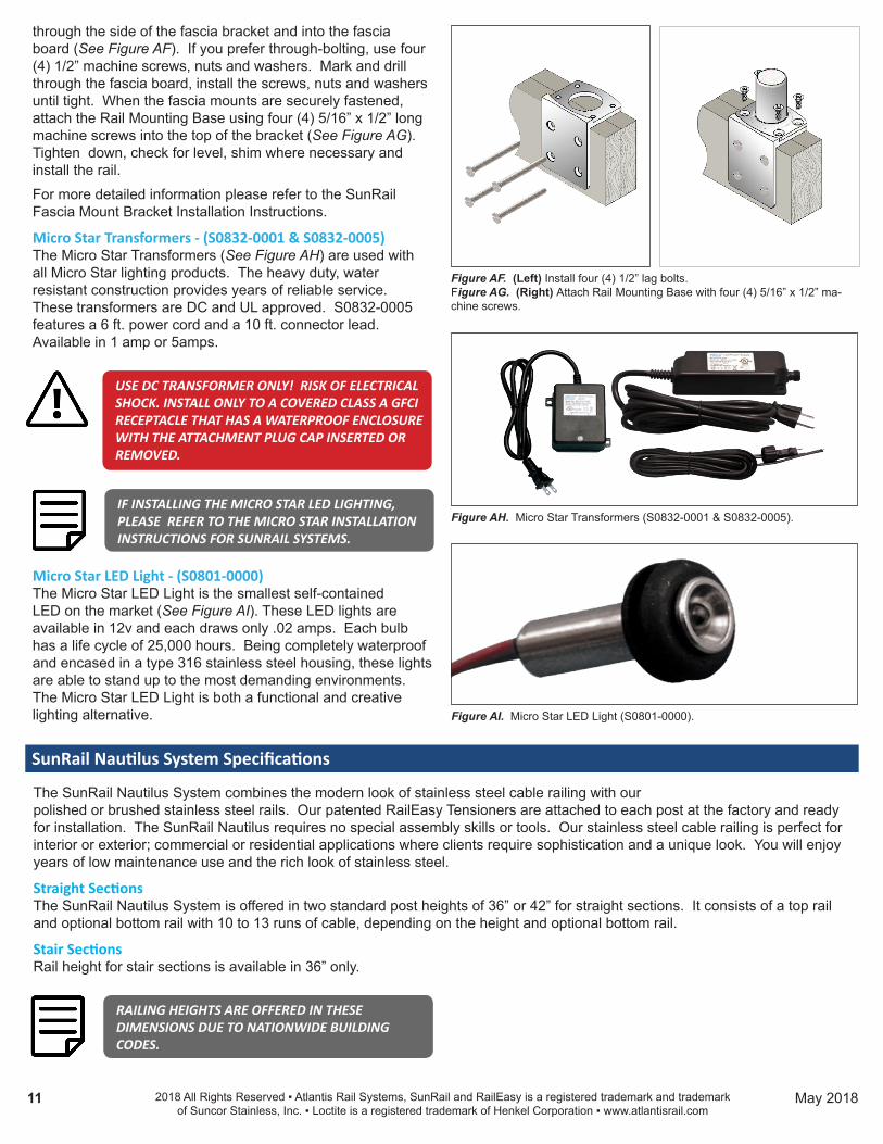
through the side of the fascia bracket and into the fascia board (See Figure AF). If you prefer through-bolting, use four (4) 1/2” machine screws, nuts and washers. Mark and drill through the fascia board, install the screws, nuts and washers until tight. When the fascia mounts are securely fastened, attach the Rail Mounting Base using four (4) 5/16” x 1/2” long machine screws into the top of the bracket (See Figure AG). Tighten down, check for level, shim where necessary and install the rail.
For more detailed information please refer to the SunRail Fascia Mount Bracket Installation Instructions.
Micro Star Transformers - (S0832-0001 & S0832-0005)The Micro Star Transformers (See Figure AH) are used with all Micro Star lighting products. The heavy duty, water resistant construction provides years of reliable service. These transformers are DC and UL approved. S0832-0005 features a 6 ft. power cord and a 10 ft. connector lead. Available in 1 amp or 5amps.
Figure AH. Micro Star Transformers (S0832-0001 & S0832-0005).
USE DC TRANSFORMER ONLY! RISK OF ELECTRICAL SHOCK. INSTALL ONLY TO A COVERED CLASS A GFCI RECEPTACLE THAT HAS A WATERPROOF ENCLOSURE WITH THE ATTACHMENT PLUG CAP INSERTED OR REMOVED.
Micro Star LED Light - (S0801-0000)The Micro Star LED Light is the smallest self-contained LED on the market (See Figure AI). These LED lights are available in 12v and each draws only .02 amps. Each bulb has a life cycle of 25,000 hours. Being completely waterproof and encased in a type 316 stainless steel housing, these lights are able to stand up to the most demanding environments. The Micro Star LED Light is both a functional and creative lighting alternative. Figure AI. Micro Star LED Light (S0801-0000).
IF INSTALLING THE MICRO STAR LED LIGHTING, PLEASE REFER TO THE MICRO STAR INSTALLATION INSTRUCTIONS FOR SUNRAIL SYSTEMS.

SunRail Nautilus Product Specifications
Between Post LengthsAtlantis Rail recommends staying within 4’ section lengths to maintain structural integrity.
Railing FinishThe SunRail Nautilus is offered in a highly polished or brushed finish. Electro-polishing is an additional finish for ocean vicinity locations. Brushed material should never be used near ocean vicinity locations.
Cable SpacingThe cable is spaced on posts at less than 3” on-center to comply with nationwide building codes.
2018 All Rights Reserved ▪ Atlantis Rail Systems, SunRail and RailEasy is a registered trademark and trademark of Suncor Stainless, Inc. ▪ Loctite is a registered trademark of Henkel Corporation ▪ www.atlantisrail.com
12 May 2018
ComponentsProduct Description Dimensions Fasteners NotesC0978-4025 RailEasy 5/32” Cable, 25ft. Spool 5/32” 1x19 316L stainless steel cable -- --C0978-4100 RailEasy 5/32” Cable, 100ft. Spool 5/32” 1x19 316L stainless steel cable -- --C0978-4500 RailEasy 5/32” Cable, 500ft. Spool 5/32” 1x19 316L stainless steel cable -- --S0982-0004 RailEasy Tensioner Round 5.50” length 1/4”-28 RH thread 3/16” rivet AdjustableS0982-S004 RailEasy Swivel End Round 2.30” length 1/4”-28 RH thread 3/16” rivet AdjustableC0989-00HD RailEasy Cable Cutter -- -- --C0196-0004-25 Stabilizer and SunRail Cable Grommets -- -- Available in 25 packsS0950-0006 Concrete Mounting Base 2” 316 stainless steel -- Anchor bolt not suppliedS0950-0002 Fascia Mount Bracket 2” 316 stainless steel -- --S0832-0001 Micro Star Transformer - 1amp 100-240Vac - 50/60HZ -- --S0832-0005 Micro Star Transformer - 5amp 100-240Vac - 50/60HZ -- --S0801-0000 Micro Star LED Light 12 Volt DC -- --