sunseeker electrical systems
TRANSCRIPT

Sunseeker Electrical SystemsSunseeker Electrical Systems
22 September 2009

Primary Systems
• There are four primary electrical systems– Solar Array and Array DC‐to‐DC Converters
– Battery and Battery Protection System
–Drive Motors (Csiro) and Motor Controller
– Controller Area Network Based Devices
2
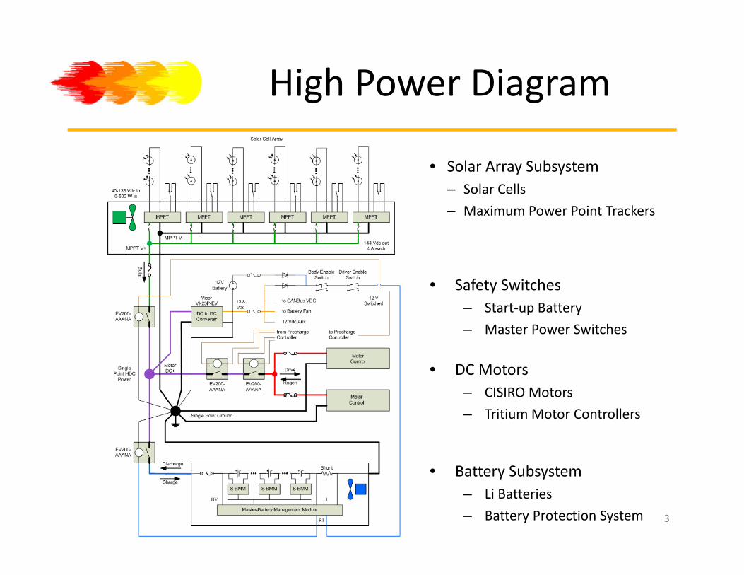
High Power Diagram
• Solar Array Subsystem– Solar Cells
– Maximum Power Point Trackers
• Safety Switches– Start‐up Battery
h
• DC Motors– CISIRO Motors
– Master Power Switches
• Battery Subsystem
CISIRO Motors
– Tritium Motor Controllers
• Battery Subsystem– Li Batteries
– Battery Protection System 3

Solar Array
• Solar Arrayy– 6 Separate Array Segments
– 14 to 16 Panels per14 to 16 Panels per Segment
– 24 Cells per Panel
4
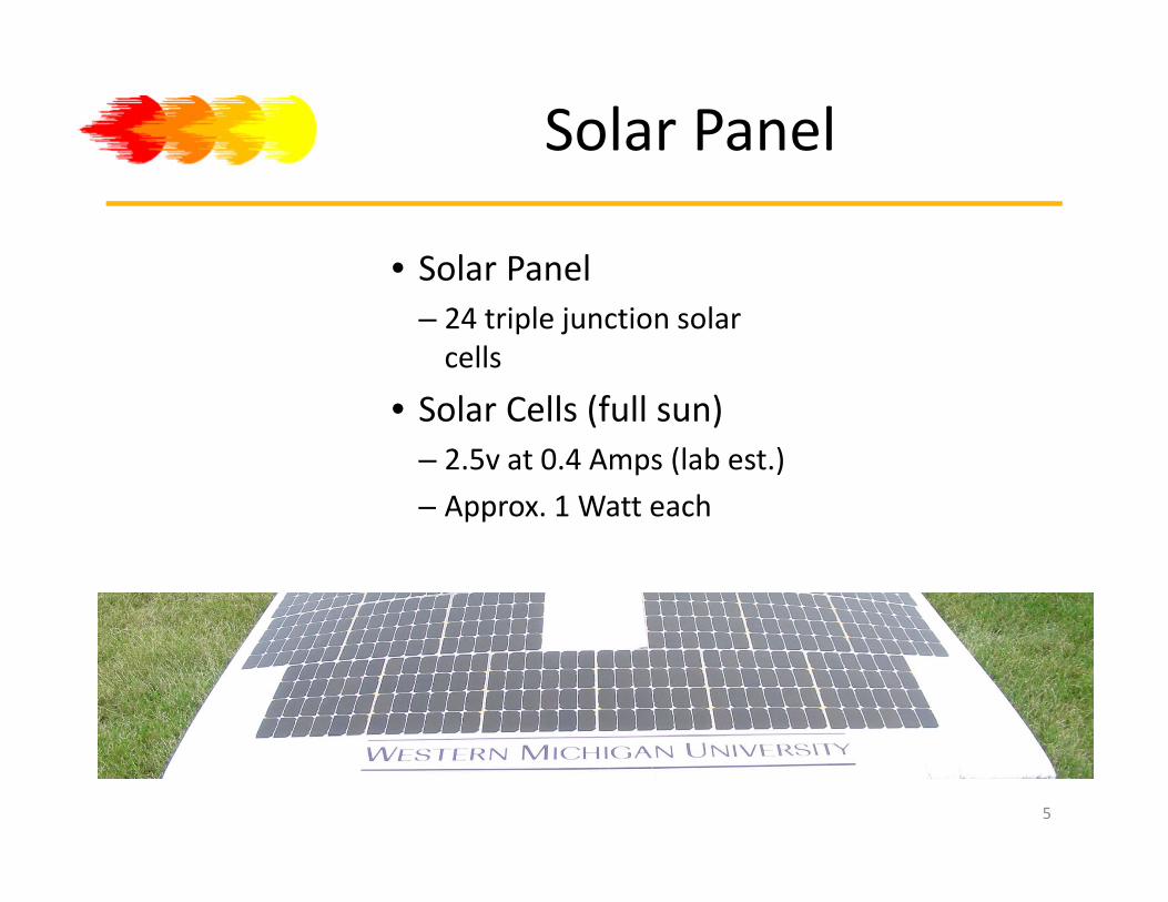
Solar Panel
• Solar PanelSo a a e– 24 triple junction solar cells
• Solar Cells (full sun)– 2.5v at 0.4 Amps (lab est.)
– Approx 1 Watt each– Approx. 1 Watt each
5
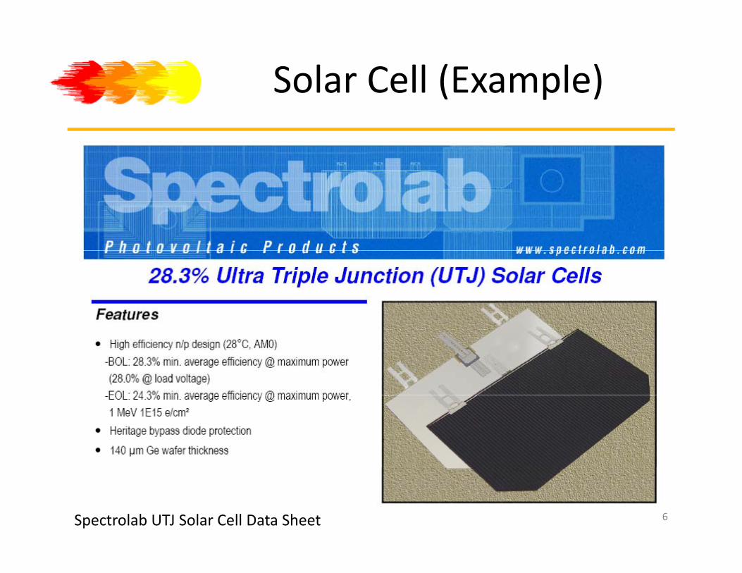
Solar Cell (Example)
Spectrolab UTJ Solar Cell Data Sheet 6

Solar Cell Specs (Example)
Try to operate at the maximum power point (2.35 V and 16.3 mA/cm2
At 26.5 cm2 for 432 mA)Spectrolab UTJ Solar Cell Data Sheet
7
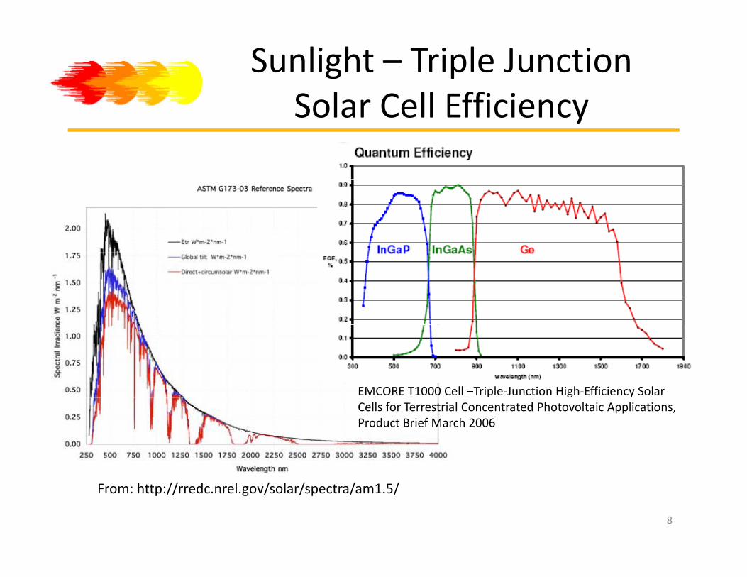
Sunlight – Triple Junction Solar Cell EfficiencySolar Cell Efficiency
EMCORE T1000 Cell –Triple‐Junction High‐Efficiency Solar Cells for Terrestrial Concentrated Photovoltaic Applications, Product Brief March 2006
From: http://rredc.nrel.gov/solar/spectra/am1.5/
8
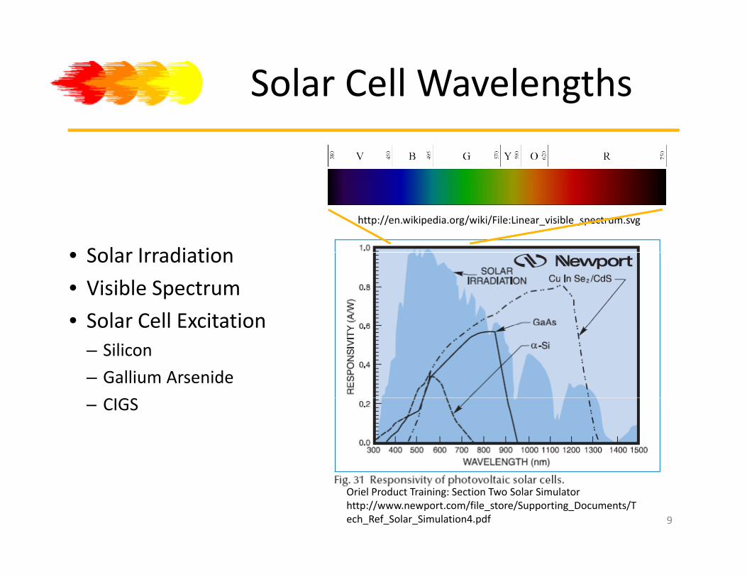
Solar Cell Wavelengths
http://en.wikipedia.org/wiki/File:Linear_visible_spectrum.svg
• Solar Irradiation• Solar Irradiation
• Visible Spectrum
• Solar Cell ExcitationSolar Cell Excitation– Silicon
– Gallium Arsenide
– CIGS
9
Oriel Product Training: Section Two Solar Simulator http://www.newport.com/file_store/Supporting_Documents/Tech_Ref_Solar_Simulation4.pdf

Solar Array Power (2005 est.)
• Solar Cell– 2.5 V at 0.4 Amps →1 Watt
• 24 Cell PanelS i C d C ll– Series Connected Cells
– 60 V at 0.4 Amps →24 Watts
• 16 Panel Subarrayy– 8 parallel, 2 series– 120 V at 3.2 Amps →384 Watts
6 S b• 6 Subarrays– 4‐16 Panel and 2‐14 Panel– 120 V at 18.4 Amps →2208 Watts
SunPower Corp. solar cells,sold and encapsulated into panels p p
by SunCat Solar
Cost: approx. $50 per encapsulated cell 10
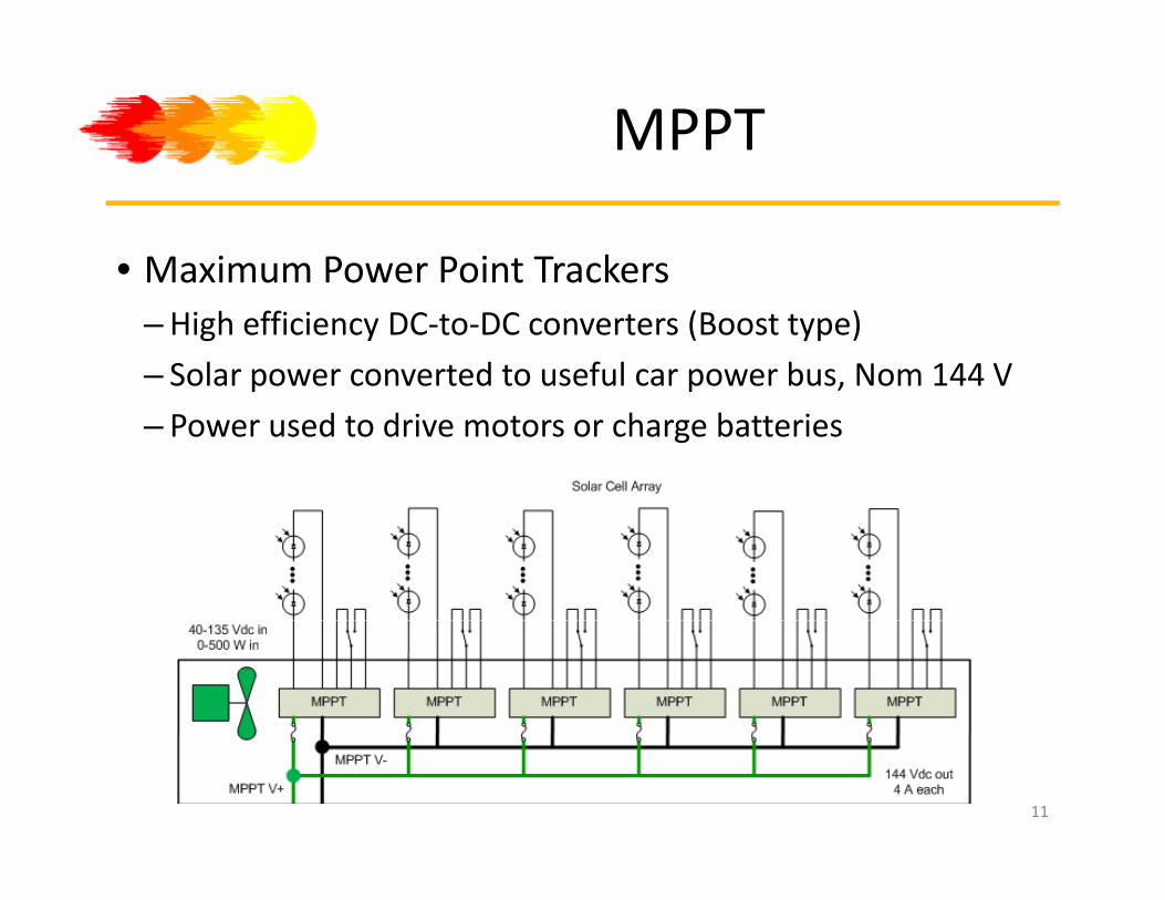
MPPT
• Maximum Power Point TrackersMaximum Power Point Trackers–High efficiency DC‐to‐DC converters (Boost type)
– Solar power converted to useful car power bus, Nom 144 V
– Power used to drive motors or charge batteries
11

MPPT
12
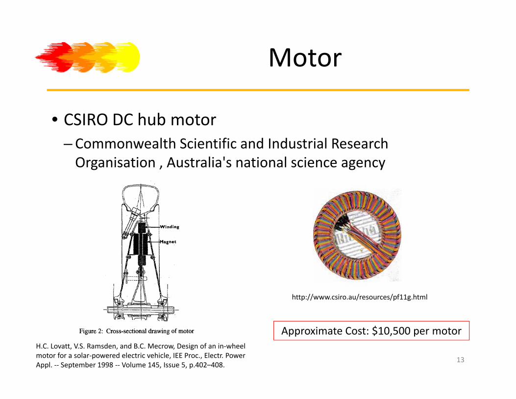
Motor
• CSIRO DC hub motorCSIRO DC hub motor– Commonwealth Scientific and Industrial Research Organisation , Australia's national science agency
http://www.csiro.au/resources/pf11g.html
H.C. Lovatt, V.S. Ramsden, and B.C. Mecrow, Design of an in‐wheel motor for a solar‐powered electric vehicle, IEE Proc., Electr. Power Appl. ‐‐ September 1998 ‐‐ Volume 145, Issue 5, p.402–408.
Approximate Cost: $10,500 per motor
13

Motor Controller
• TritiumTritium WaveSculpter Motor Controller– Tritium Pty Ltd
14

Motor and CAN
• Motor Controller– CAN Commands and Status
– Power Inductors to motor
• Precharge Controller– Charge Motor CapacitorsCharge Motor Capacitors before operation
– Fuses to limit current
– New module has CAN– New module has CAN interface
15

Battery and BPS
• Li‐Polymer BatteriesLi Polymer Batteries–Max. 168 V, Nom. 144V
–Max. Current ~60 Amps
16

Li‐Polymer Battery
• EEMB Battery: LP505590 Celly–Data sheet information: Nom. 3.7 V, C = 2600 mAh
– 1 C charge and 2 C discharge
– 52.5+/‐5 grams each
17

Sunseeker NASC Design
• 25 kg of Li‐Polymer batteries allowed, NASC Regulation25 kg of Li Polymer batteries allowed, NASC Regulation
• How do we get 144V at 30 A?–Using 3.6 V, there are 40 batteries in seriesUsing 3.6 V, there are 40 batteries in series
– Based on 25 kg, there can be ~476+/‐ batteries
– Therefore, 11 cells in parallel x 40 modules in series (440 used)
• Nominal 144V at 28.6 Ah (peak discharge 57.2 Amps)
18

Battery System Design
• 40‐Series modules40 Series modules– 11 Parallel Batteries
– Slave battery protection monitor
• Battery Protection System–One slave per module
O t / CAN I/F–One master w/ CAN I/F
–Measure:• Total V, Cell V, Total Current, , , ,Temperature
19

Controller Area Network
• Controller Area Network– An automotive serial data bus
– Accelerate by wire
Commands and status information– Commands and status information
• Connections– Motor Controller
– Driver Controller
– Motor Precharge Controller
– Driver DisplaysDriver Displays
– Battery Protection System
– Telemetry
h ll– Light Controller
20

What is CAN?
• CAN (Controller Area Network) is a host‐less, vehicleCAN (Controller Area Network) is a host less, vehicle bus standard that allows for communication between microcontrollers
• CAN packets sent across the network can be read and interpreted by the various microcontrollers
• CAN is naturally redundant– CAN‐Hi
– CAN‐Low
21
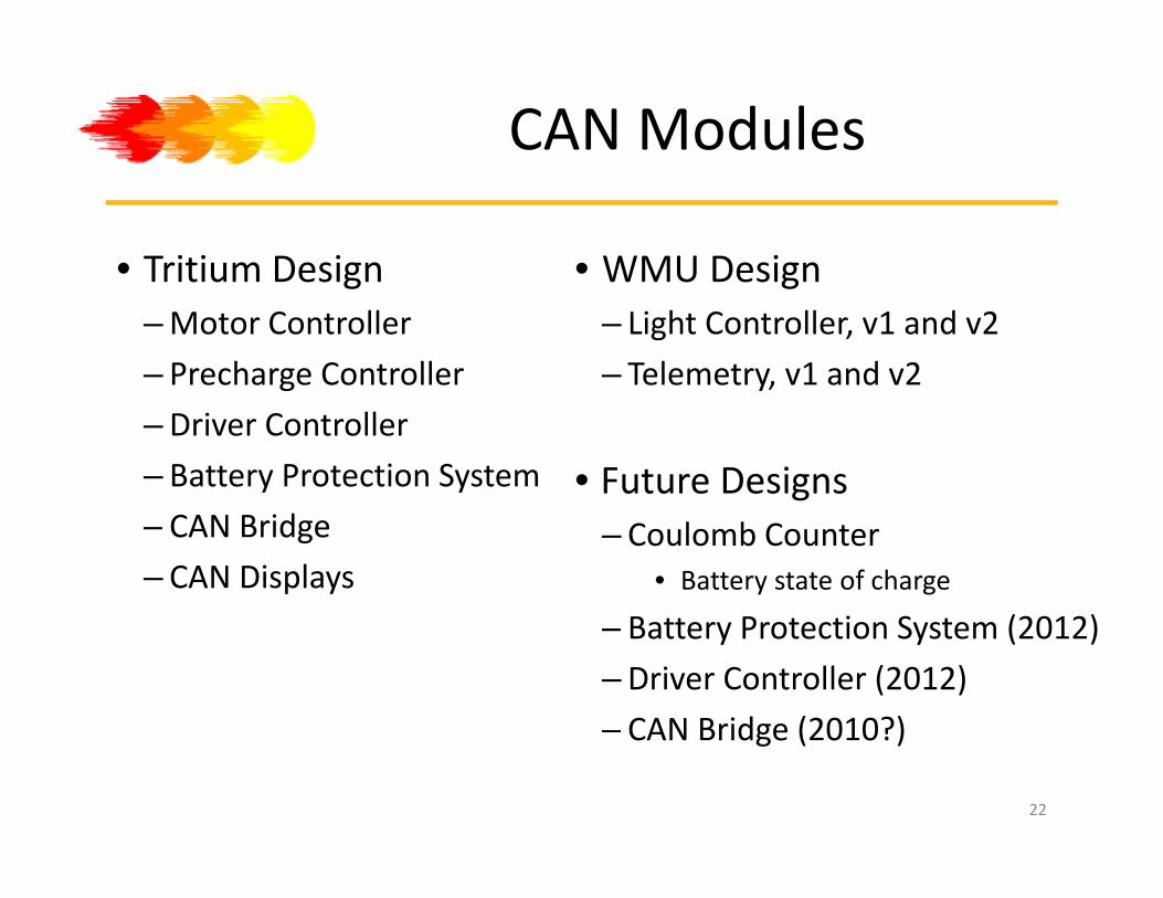
CAN Modules
• Tritium Design • WMU DesignTritium Design–Motor Controller
– Precharge Controller
WMU Design– Light Controller, v1 and v2
– Telemetry, v1 and v2
–Driver Controller
– Battery Protection System • Future Designs– CAN Bridge
– CAN Displays– Coulomb Counter
• Battery state of charge
B tt P t ti S t (2012)– Battery Protection System (2012)
–Driver Controller (2012)
– CAN Bridge (2010?)CAN Bridge (2010?)
22
Light Controller Board Function and UpdatesFunction and Updates
• Responds to driver control switch position CAN dataResponds to driver control switch position CAN data– Apply power to appropriate indicator lights:Brake lights, turn signals and hazard lights
• V2 Updates to Light Controller Board• CAN clock for MSP430
• Allow high data rate for CAN operation (eliminated bug)
• Improved Power SchemeImproved Power Scheme
• Removed ribbon components
23

Telemetry Board Operation
• Captures all CAN packets and stores/transmits CANCaptures all CAN packets and stores/transmits CAN data–Wireless modem communication to chase vehicle (RS‐232)
–USB memory stick storage of telemetry data (black box)
• V2 Updates to Telemetry Board–More advanced MSP430 microcontroller
– CAN Clock for improved UART operation
–Dual CAN capable with improved power scheme
l–UART USB storage implementation
24

Telemetry Message Structure and Contentand Content
• Read from CAN packets p(address and data)– Motor Controller: 14 addresses with data
Driver Controller: 4 addresses with data– Driver Controller: 4 addresses with data
• Fixed ASCII character string– Sent to chase vehicle
– Saved to local USB memory storage
25
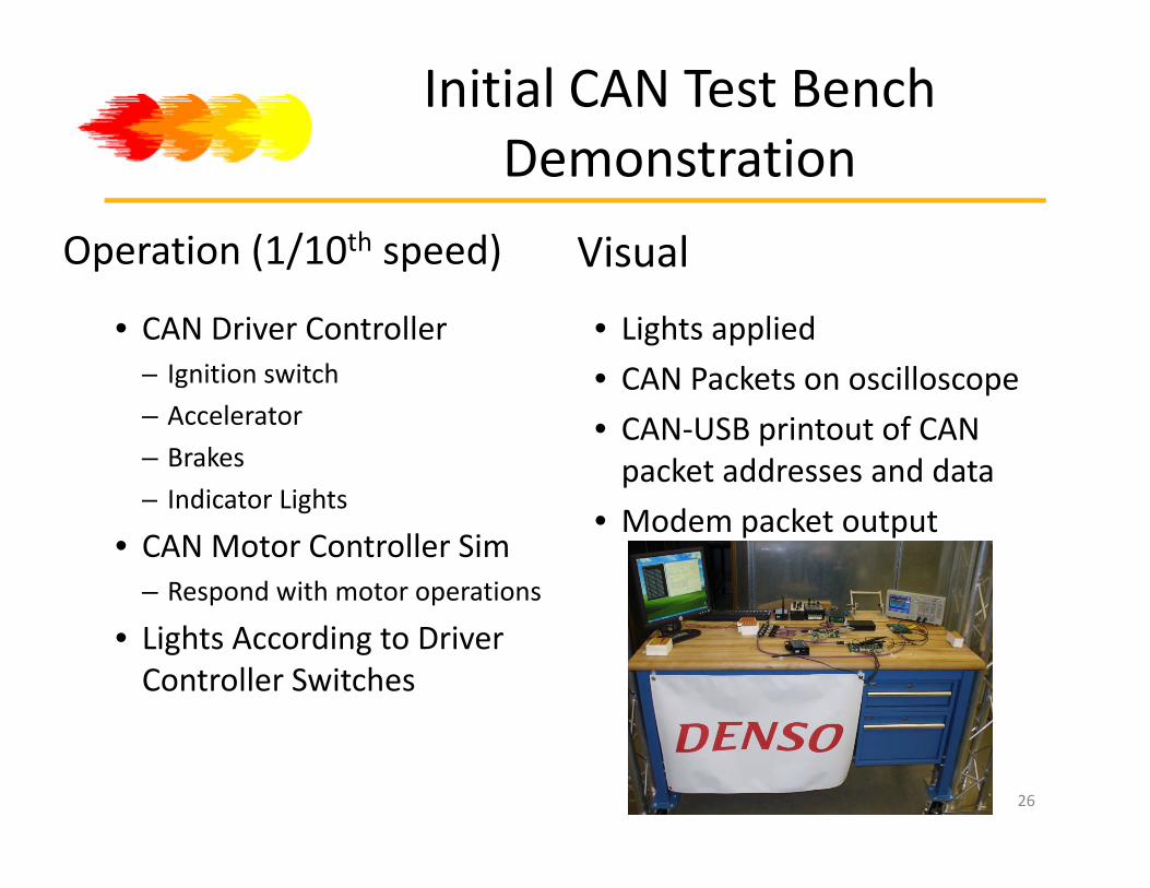
Initial CAN Test Bench DemonstrationDemonstration
Operation (1/10th speed) Visual
• CAN Driver Controller – Ignition switch
• Lights applied
• CAN Packets on oscilloscope– Accelerator
– Brakes
– Indicator Lights
CAN Packets on oscilloscope
• CAN‐USB printout of CAN packet addresses and data
– Indicator Lights
• CAN Motor Controller Sim– Respond with motor operations
• Modem packet output
• Lights According to Driver Controller Switches
26

Test Bench As a Sunseeker Mock upMock‐up
• All expected CAN activityAll expected CAN activity
• Allow all modules to be tested under normal and abnormal conditions
• Allow all software to be integrated before being installed in the car
• Expect easier support, faster installation, better p pp , ,performance
… leading to a faster and safer vehicle.
27

Sunseeker Electrical Teams
• BatteryBattery– Characterize batteries
– Build and maintain 2010 battery
• Solar Array– Construct an I‐V curve tester
– I‐V curve testing of existing module: good, bad, array groups
• CAN Support–Debug v2 PCBs: debug, find and fix errors and layout and fab new PCBs
Software documentation testing corrections and updates– Software documentation, testing, corrections, and updates• Driver controller, light controller, and telemetry.
28

Future Projects
• Coulomb CounterCoulomb Counter– Battery state of charge
• Battery Protection Systemy y
• Custom Driver Controller with displays– Eliminate CAN bridgeg
29