super-elastic flexible jaw assembly
TRANSCRIPT

United States Patent US006190399B1
(12) (10) Patent N0.: US 6,190,399 B1 Palmer et al. (45) Date of Patent: *Feb. 20, 2001
(54) SUPER-ELASTIC FLEXIBLE JAW 3,989,049 11/1976 Yoon. ASSEMBLY 4,200,111 4/1980 Harris.
4,393,872 7/1983 ReZnik et a1. .
(75) Inventors: Matthew A. Palmer, Miami; Charles 474277014 * 1/1984 BeTet ‘11-
I‘I Slater, Fort Lauderdale; David ...................... .. Turkel, Alva; John Whittier, Miami, 478967678 1/1990 ogaag . .
all of FL (US) ’ ’ '
(List continued on next page.) (73) Assignee: SciMed Life Systems, Inc., Maple
Grove, MN (Us) OTHER PUBLICATIONS
FlexMedics, “Nitinol . . . The Material of Choice for Safer
( * ) Notice: Under 35 U.S.C. 154(b), the term of this More Effective Medical Procedures”, Advertisement 1989. patent shall be extended for 0 days. P. 81 from a program from the 4th World Congress of
Endoscopic Surgery discloses a lecture entitled “Superelas This patent is subject to a terminal dis- tic, Ceramic Materials and Microsystems, Key Technologies claimer. for Endoscopic”.
The article entitled “Shape—Memory Alloys” from Scienti?c (21) Appl' NO‘: 08/952’010 American, Nov. 1979 vol. 241, No. 5 pp. 74—82 disclosed (22) PCT Filed; May 10, 1996 hoW alloys forming a shape at a certain temperature can be
deformed at. (86) PCT N05 PCT/US96/06924 The article entitled “Using Shape Memory Alloys” by
§ 371 Date: Feb‘ 9’ 1998 Hodgson in 1988 discloses hoW'shape memory alloys have the ability to respond With signi?cant force and motion to
§ 102(@) Date; Feb, 9, 1998 small changes in ambient.
(87) PCT pub NO; W096/35374 Primary Examiner—Michael BuiZ Assistant Examiner—(Vikki) Hoa B. Trinh
PCT Pub. Date: NOV- 14, 1996 (74) Attorney, Agent, or Firm—Finnegan, Henderson, FaraboW, Garrett & Dunner, L.L.P.
Related US. Application Data (57) ABSTRACT
(63) 5:; H5153; his‘; fpgEplggiitgoégg'zgé/ 440’326’ ?led on May A jaW assembly for an endoscopic bioptome includes a pair ’ ’ ’ ’ of opposed end effectors having resilient arms formed from
IIlt. Cl-7 ................................................... .. a super_elastic {metal' The ends of the resilient arms
(52) ........ .. 606/205 terminate in end effector jaW cups Which are also preferably (58) Field of Search ................................... .. 606/205—208; formed from super-elastic metal, While the proximal por
81/418, 421; 30/186 tions of the resilient arms include angled portions Which urge the jaW cups aWay from each other. The jaW cups are
(56) References Cited brought together into a biting action by a cylinder having a sharp distal edge Which moves relative to and over he arms
U~S~ PATENT DOCUMENTS of the end effectors. As the resilient arms are formed from a
370017522 9/1961 Silverman_ super-elastic metal, they exhibit very high resiliency and 3,175,554 3/1965 Stewart _ durability even after numerous uses.
3,404,677 10/1968 Springer. 3,989,033 11/1976 Halpern et a1. . 29 Claims, 14 Drawing Sheets
340 399 340 318 342 3440 /
1

US 6,190,399 B1 Page 2
US. PATENT DOCUMENTS 5,352,235 10/1994 Koros et a1. . 5,352,237 10/1994 Rodak et a1. .
479257445 5/1990 Sak‘FFIOFO 6‘ a1- - 5,358,796 10/1994 Nakamura et a1. .
279357325 * 123/133; gemfcmé 6]‘ a1- - 606 205 5,368,661 11/1994 Nakamura et a1. . 7 7 / WY f”, 7 r' """""""""""" " / 5,535,754 * 7/1996 Doherty ............................. .. 606/205
5,172,700 12/1992 Benclnl et a1. . 5,542,432 8/1996 Slater et a1. .
5,254,130 10/1993 Poncet et a1. . 5722 421 * 3 1998 F t 1 606 205 X 572817230 1/1994 Heidmueller . , , / rancese e a . ............... .. /
5,334,198 8/1994 Hart et a1. . 5,341,818 8/1994 Abrams et a1. . * cited by examiner


U.S. Patent Feb. 20, 2001 Sheet 2 0f 14 US 6,190,399 B1
23202 / 2360.2
n Qzsomson .2260,226b
2240,224b
4 2280,228b
a 2380,238b
2360,236b
2240,224b
2340,234b
2280.228b 2380,238b
FIG. 1d FIG- 16

U.S. Patent Feb. 20, 2001 Sheet 3 0f 14 US 6,190,399 B1
555% m .5 02/09/0999,
43 N .OE

2001 Sheet 5 0f 14 US 6,190,399 B1 U.S. Patent Feb. 20,

U.S. Patent Feb. 20, 2001 Sheet 6 0f 14 US 6,190,399 B1
on .QE

U.S. Patent Feb. 20 2001 Sheet 7 0f 14 US 6,190,399 B1
UK .QE

U.S. Patent Feb. 20, 2001 Sheet 8 0f 14 US 6,190,399 B1
5. .07. E .90

U.S. Patent Feb. 20, 2001 Sheet 9 0f 14 US 6,190,399 B1
145 \0 18 140 “: 145C
./" ~18o 145b
FIG. 8b
2?:50 40 18
QLZArSb 180
245C
FIG. 9b

U.S. Patent Feb. 20, 2001 Sheet 10 0f 14 US 6,190,399 B1
00 _‘ .OE
in
/./ 8% 03M .3»,
8% w;
Non 0R / “ r \ f \
N3) 8%

U.S. Patent Feb. 20, 2001 Sheet 11 0f 14 US 6,190,399 B1
f . 4470 r 444
FIG. 11b

U.S. Patent Feb. 20, 2001 Sheet 12 0f 14 US 6,190,399 B1
(
Q 25500 {5510
/ N5520 5440 5530,5550 G. 1 2
506 160
16
255355550 5445 \ \\552b
FQFW \ 55% 5510 5500
5520
5550
FIG. ‘I20 5530
\ 4G O 232:; /- 5520
5145 55"’
FIG. 12b


U.S. Patent Feb. 20, 2001 Sheet 14 0f 14 US 6,190,399 B1
21 .OE
moo ommw wwm J /
n ~ ~ ~ ~ ~ ~ N ~ ~ ~ ~ ~ ~ > N ~ ~ N N ~ ~ ~ ~ ~ ~ N ~ MN

US 6,190,399 B1 1
SUPER-ELASTIC FLEXIBLE JAW ASSEMBLY
This is a 371 of Int’l Application Serial No. PCT/US96/ 06924 ?led May 10, 1996, noW Int’l Publication No. WO 96/35374, Which is a continuation of US. application Ser. No. 08/440,326 ?led May 12, 1995, now US. Pat. No. 5,638,827, Which are incorporated herein by reference.
FIELD OF THE INVENTION
This invention relates to endoscopic surgical instruments. More particularly, this invention relates to super-elastic jaW assemblies for multiple sample endoscopic instruments.
STATE OF THE ART
Endoscopic biopsy procedures are typically performed With an endoscope and an endoscopic biopsy forceps device (bioptome). The endoscope is a long ?exible tube carrying ?ber optics and having a narroW lumen through Which the bioptome is inserted. The bioptome typically includes a long ?exible coil having a pair of opposed jaWs at the distal end and manual actuation means at the proximal end. Manipu lation of the actuation means opens and closes the jaWs. During a biopsy tissue sampling operation the surgeon guides the endoscope to the biopsy site While vieWing the biopsy site through the ?ber optics of the endoscope. The bioptome is inserted through the narroW lumen of the endoscope until the opposed jaWs arrive at the biopsy site. While vieWing the biopsy site through the ?ber optics of the endoscope, the surgeon positions the jaWs around a tissue to be sampled and manipulates the actuation means so that the jaWs close around the tissue. A sample of the tissue is then cut and/or torn aWay from the biopsy site While it is trapped betWeen the jaWs of the bioptome. Keeping the jaWs closed, the surgeon WithdraWs the bioptome from the endoscope and then opens the jaWs to collect the biopsy tissue sample. A biopsy tissue sampling procedure often requires the
taking of several tissue samples either from the same or from different biopsy sites. Unfortunately, most bioptomes are limited to taking a single tissue sample, after Which the device must be WithdraWn from the endoscope and the tissue collected before the device can be used again to take a second tissue sample. The single-sample limitation of most bioptomes is due to the limited space betWeen the biopsy forceps jaWs. Several attempts have been made to provide an instrument Which Will alloW the taking of several tissue samples before the instrument must be WithdraWn and the samples collected. Problems in providing such an instrument include the extremely small siZe required by the narroW lumen of the endoscope and the fact that the instrument must be ?exible in order to be inserted through the lumen of the endoscope. Thus, several knoWn multiple sample biopsy instruments are precluded from use With an endoscope because of their siZe and rigidity. These include the “punch and suction type” instruments disclosed in US. Pat Nos. 3,989,033 to Halpern et al. and 4,522,206 to Whipple et al. Both of these devices have a holloW tube With a punch at the distal end and a vacuum source coupled to the proximal end. A tissue sample is cut With the punch and suctioned aWay from the biopsy site through the holloW tube. It is generally recogniZed, hoWever, that suctioning tissue samples through a long narroW ?exible bioptome is virtually impossible.
Copending application U.S. Ser. No. 08/189,937 discloses an endoscopic multiple sample bioptome Which alloWs for the taking of multiple samples before removal of the biop tome from the endoscope. The multiple sample bioptome
10
15
20
25
30
35
40
45
55
60
65
2 includes a holloW outer member and an axially displaceable inner member extending therethrough. The proximal ends of the outer and inner members are coupled to an actuator for axially displacing one relative to the other. The distal end of the outer member is coupled to one of a cylinder having a sharp distal edge and a jaW assembly, While the distal end of the inner member is coupled to the other. The jaW assembly includes a pair of opposed, preferably toothed jaW cups each of Which is coupled by a resilient arm to a base member. The arms are bent to urge the jaWs aWay from each other. The base member is mounted inside the cylinder and axial movement of the jaW assembly and cylinder relative to each other draWs the arms into the cylinder (or extends the cylinder over the arms) and brings the jaW cups together in a biting action. In this manner, multiple samples from a patient can be taken and stored Within the jaW assembly before needing to retrieve the bioptome from the patient. A family of alloys knoWn to exhibit unusual elasticity and
?exibility properties has recently been identi?ed as having useful practical applications. These alloys speci?cally exhibit What is called the shape memory effect. This effect provides that if such an alloy is plastically deformed from its original shape at one temperature, it Will completely recover its original shape on being raised to a higher temperature. In recovering their shapes these alloys can produce a displace ment or a force, or a combination, as a function of the temperature. Due to the unique atomic structure necessary for the memory shape effect to take place, these alloys exhibit other properties as Well, such as super-elasticity or pseudo-elasticity.
The type of transformation Which occurs in the shape memory alloys is knoWn as a martensitic transformation and changes the material from a high temperature form, called austenite, to a loW temperature form called martensite. For a given shape memory alloy, the transformation betWeen martensite form and austenite form occurs at a predictable temperature, knoWn as the transformation temperature.
In order for an alloy to exhibit the shape-memory effect, it must ?rst be bent into the shape to be “memorized” at room temperature. The alloy is then heated until it assumes a high-temperature con?guration called the beta or parent phase, Where the crystal structure of the metal assumes its austenite form Which it Will “remember”. Next, the alloy is rapidly cooled so that the atoms in the alloy rearrange themselves into the crystal form of martensite. The alloy may then be bent into a neW shape Which it Will maintain as long as the temperature remains beloW the transformation temperature. If the alloy is subsequently reheated above its transformation temperature so that the alloy structure reverts to an austenite form, it Will recover its previously memo riZed shape. Shape memory alloys exhibit signi?cantly increased resiliency relative to their non-superelastic counterparts, because the atoms of the memory metal shift back and forth betWeen martensite and austenite forms, and do not slip into neW dislocated con?gurations as is the case With normal metals.
Useful temperature independent properties are also exhib ited by memory-shape alloys. In an alloy that has a beta phase capable of producing martensite under stress, one can observe an unusual elastic property called super-elasticity or pseudo-elasticity. In a typical alloy With this property, the metal exhibits normal elastic behavior under stress (that is, it gets longer in some dimensions) until the critical stress is reached at Which point martensite molecular structures begin to form. With further stress, the specimen continues to elongate, as if it Were being plastically deformed. When the stress is removed, the martensite structure reverts to the

US 6,190,399 B1 3
parent phase, or austenite structure, and the metal contracts to its original dimensions, shoWing no permanent deforma tion.
Presently, the applications of shape memory materials in medical apparatuses are very limited. US. Pat. No. 4,925, 445 to Sakamoto et al. discloses a guide Wire for a catheter, Where the guide Wire has a rigid body and a ?exible distal end made of a memory-shape metal alloy With the super elastic properties described above. The distal end of the Wire is curved back such that a blunt forWard tip is formed. With a super-elastic distal end, the guide Wire can be guided through the blood vessel of a patient Without the risk of permanently deforming the tip of the Wire, Which could result in the tearing of the blood vessel Walls or in the misguiding of the Wire. US. Pat. No. 5,254,130 to Poncet et al., similarly uses a memory-shaped alloy as a push rod and steering means for steering a distal clevis and attached end effectors. As the push rod is extended outside of the housing Where it is held prior to deployment, the push rod assumes a remembered con?guration relative to the straight housing, and hence steers the end effectors to a desired position. Other than the steering functions disclosed in the Sakamoto et al. and Poncet et al. patents, hoWever, the super-elasticity of shape memory alloys has not been used in medical apparatus of the art.
SUMMARY OF THE INVENTION
It is therefore an object of the invention to provide a jaW assembly for a bioptome Where at least portions of the jaW assembly are made out of a superelastic metal.
It is another object of the invention to provide a jaW assembly for an endoscopic multiple sample bioptome Where the jaW arms are superelastic and ?exible and repeat edly return to desired positions Without fracturing or deforming.
It is a further object of the invention to provide a jaW assembly for an endoscopic multiple sample bioptome Where the arms of the jaW assembly undergo insigni?cant plastic deformation even after repeatedly being opened and forced closed.
It is also an object of the invention to provide a jaW assembly for an endoscopic multiple sample bioptome Which is simple to assemble.
In accord With these objects Which Will be discussed in detail beloW, an endoscopic bioptome is provided With a jaW assembly, a tubular member, and an axially displaceable Wire extending through the tube member, Where the distal end of the Wire and tubular member are both coupled to the jaW assembly, and the jaW assembly includes a pair of opposed end effectors having resilient arms formed from a superelastic metal. According to a ?rst embodiment of the invention, the proximal ends of the resilient arms include angled portions, While the distal ends terminate With end effector jaW cups, Which are also preferably formed from a superelastic metal. The resilient arms urge the jaW cups aWay from each other. As the resilient arms are formed from a superelastic alloy, they exhibit very high resiliency and durability even after numerous uses. Other embodiments of the jaW assembly include arms having mounting holes and cups having radially arranged teeth and closing cams. Another embodiment of the jaW assembly includes arms having proximal semi-cylindrical portions With distally extending tabs. Different types of mounting screWs are provided for coupling the proximal ends of the arms of the jaWs to the distal end of the tubular member.
According to preferred aspects of the invention, the tubular member is a ?exible coil, and the proximal portion
10
15
25
35
45
55
65
4 of each arm is mounted inside the distal end of the tubular member by means of a threaded screW and Washer (or retaining sleeve) threaded in the coil. The distal end of the Wire is coupled to a cylinder Which is preferably provided With a knife sharp distal edge. Different embodiments for coupling the distal end of the Wire to the cylinder are disclosed. The proximal ends of the coil and Wire are coupled to a manual actuation means for axially displacing one of the coil and Wire relative to the other. Axial move ment of the Wire relative to the coil moves the cylinder over the arms of the end effectors and over the necks of the jaW cups, thereby forcing the jaW cups together in a biting action.
According to another embodiment of the invention, a laparoscopic type multiple sample bioptome is provided With the super-elastic jaW assembly of the invention. The laparoscopic type bioptome is provided With a relatively rigid holloW tube, and a relatively rigid rod Which extends therethrough. The distal end of the rod is coupled to the jaW assembly described in the ?rst embodiment, and the distal end of the tube is provided With a knife-sharp edge similar to the cylinder edge described above. The proximal end of the rod is coupled to a ?xed portion of a handle and the proximal end of the tube is coupled to a movable lever portion of the handle. Movement of the lever of the handle results in longitudinal movement of the tube relative to the rod and effects and closing of the jaWs as described above.
Additional objects and advantages of the invention Will become apparent to those skilled in the art upon reference to the detailed description taken in conjunction With the pro vided ?gures.
BRIEF DESCRIPTION OF THE DRAWINGS
FIG. 1 is a side elevation vieW in partial section of the proximal end of a ?rst embodiment of the invention;
FIG. 1a is a plan vieW of one hermaphroditic part of a tWo part spool according to a preferred embodiment of the invention;
FIG. 1b is a side elevation vieW of the one part of the tWo part spool;
FIG. 1c is a proximal end vieW of the one part of the tWo part spool;
FIG. 1a' is a distal end vieW of the one part of the tWo part spool;
FIG. 16 is a broken schematic section illustrating a leaf spring locking of tWo parts of the tWo part spool;
FIG. 2 is an enlarged transparent side elevation vieW of the distal end of a ?rst embodiment of the invention With the jaWs open;
FIG. 3 is an enlarged exploded side vieW of the distal end of a ?rst embodiment of the invention;
FIGS. 4a and 4b are respectively a front vieW of the threaded screW and a front vieW of the Washer of FIG. 3;
FIG. 4c is a cross sectional vieW taken along line C—C of the arms of the jaW assembly shoWn in FIG. 3;
FIG. 5 is an enlarged transparent side elevation vieW of the distal end of a ?rst embodiment of the invention With the jaWs closed;
FIG. 6 is an enlarged transparent top elevation vieW of the distal end of a ?rst embodiment of the invention;
FIGS. 7a through 76 are enlarged transparent side eleva tional vieWs of the distal end of the ?rst embodiment, shoWing a sequence of biopsy sampling operations;
FIGS. 7f through 7h are vieWs similar to FIG. 6 shoWing the cutting action of the knife-sharp distal edge of the cylinder;

US 6,190,399 B1 5
FIG. 8a is an enlarged broken side elevation vieW of a different embodiment of control Wire coupling;
FIG. 8b is a cross sectional vieW along line B—B in FIG.
10a; FIG. 9a is a vieW similar to FIG. 8a but of yet another
embodiment of control Wire coupling; FIG. 9b is a cross sectional vieW along line B—B of FIG.
9a; FIG. 10 is a broken side elevation vieW in partial section
of a second embodiment of the invention;
FIG. 10a is an enlarged transparent side elevation vieW of the jaW assembly to push rod and outer tube coupling of the second embodiment of the invention of FIG. 10 With the jaWs open;
FIG. 11 is an exploded perspective vieW of another embodiment for mounting jaWs on the distal end of a coil;
FIG. 11a is a sectional vieW taken along the line 11a—11a in FIG. 11;
FIG. 11b is a vieW similar to FIG. 11 With the jaWs coupled to the distal end of the coil;
FIG. 12 is an enlarged exploded side elevation vieW of another embodiment for mounting jaWs on the distal end of a coil;
FIG. 12a is a broken perspective vieW of a jaW arm according to the embodiment of FIG. 12;
FIG. 12b is broken side elevation vieW of the embodiment of FIG. 12 in a partially assembled state;
FIG. 12c is a sectional vieW taken along line 12c—12c in FIG. 12b;
FIG. 13 is an exploded side elevation vieW of a presently preferred embodiment for mounting jaWs on the distal end of a coil;
FIG. 13a is and enlarges distal end vieW of the screW in FIG. 13;
FIG. 13b is a reduced, partially transparent, side elevation vieW of the embodiment of FIG. 13 as assembled prior to attachment to the distal end of a coil;
FIG. 14 is an enlarged side elevation vieW of another embodiment for coupling a cylindrical sleeve to the distal end of a control Wire;
FIG. 14a is a top vieW of the embodiment of FIG. 13; and
FIG. 14b is an enlarged sectional vieW taken along lines 13b—13b of FIG. 13.
DETAILED DESCRIPTION OF THE PREFERRED EMBODIMENTS
Referring noW to FIGS. 1 through 6, a ?rst embodiment of the multiple sample bioptome With the super-elastic ?exible jaW assembly is shoWn and includes a proximal handle portion 12 and a distal end effector portion 14. Along ?exible coil 16, and an axially displaceable control Wire 18 Which extends through the coil 16 couples the handle portion 12 to the end effector portion 14. The coil 16 is preferably covered With a PTFE, FEP or polyole?n sheath 15 along substantially all of its length and a strain relief sleeve 17 covering a portion of the coil Which extends from the handle 12. The coil 16, by its nature is effectively internally threaded and can receive a screW With mating threads as discussed in further detail beloW at its open distal end 16a Which is preferably ground ?at 16b. The control Wire 18 is preferably ?exible but longitudinally inelastic and is ideally formed from 304 Steel and provided With an outer diameter of approximately 0.017—0.018 inch. The proximal handle
10
15
25
35
55
65
6 portion 12 includes a central shaft 20 and a displaceable spool 22. The proximal end of the shaft 20 is provided With a thumb ring 24 and a longitudinal bore 26 is provided at the distal end of the shaft 20. Alongitudinal slot 28 extends from the proximal end of bore 26 to a point distal of the thumb ring 24. The displaceable spool 22 is provided With a cross member 30 Which passes through the slot 28 in the central shaft 20. The cross member 30 is provided With a central through hole 32 and a radially engaging set screW 34. According to the ?rst embodiment of the invention, a short bore 36 and a radially engaging set screW 38 are provided in the shaft 20 distal of the thumb ring 24 With the bore 36 communicating With the longitudinal slot 28. In the ?rst embodiment of the invention, the proximal end of the coil 16 extends into the central through hole 32 in the cross member 30 and is ?xed there by the set screW 34. The proximal end of the control Wire 18, passes through slot 28, is inserted into the short bore 36, and held there by the set screW 38. From the foregoing, those skilled in the art Will appreciate that relative movement of the shaft 20 and spool 22 results in movement of the control Wire 18 relative to the coil 16. Such action results in actuation of the end effectors as described in detail beloW.
According to a preferred embodiment of the invention, an hermaphroditic tWo part snap-together spool is used. FIGS. 1a through 16 illustrate the principal features of each part 222a (222b) of a snap together spool. TWo identical her maphroditic parts 222a (222b) each represent one half of the spool. Each part 222a (222b) is substantially semi cylindrical With a spool shaped outer pro?le. Acoil engaging member 224a (224b) extends radially inWard Within a semi-cylindrical recess 226a (226b) Which extends the entire length of the part 222a (222b). Each part 222a (222b) is provided With a pair of diametrically opposed locking tabs 228a (228b), 230a (230b) and a pair of diametrically opposed tab receiving slots 232a (232b), 234a (234b). In addition, each part 222a (222b) is provided With a pair of diametrically opposed guide pins 236a (236b), 238a (238b) and a pair of diametrically opposed pin receiving holes 240a (240b), 242a (242b). From the foregoing, it Will be appre ciated that When the tWo parts 222a, 222b are assembled, the guide pins 236a, 238a on part 222a enter the pin receiving holes 240b, 242b, respectively, on part 222b; and the locking tabs 228a, 230a on part 222a enter the tab receiving slots 232b, 234b, respectively, on part 222b. Similarly, the guide pins 236b, 238b on part 222b enter the pin receiving holes 240a, 242a, respectively, on part 222a; and the locking tabs 228b, 230b on part 222b enter the tab receiving slots 232a, 234a, respectively, on part 222a. Prior to the snapping the parts together, the proximal end of the coil 16 (FIG. 1) With a crimp band (not shoWn) on its end, is placed betWeen the coil engaging members 224a, 224b. When the parts 222a, 222b are assembled the respective coil engaging members 224a, 224b hold the proximal end of the coil securely.
According to a preferred aspect of the tWo part spool, the tab receiving slots are provided With leaf springs to inhibit the tWo parts from coming apart. FIG. 16 illustrates the leaf spring schematically With reference to the tab 228a on part 222a as it engages the slot 232b on part 222b. As seen in FIG. 16, the slot 232b is partially occluded by a depending arm 233b Which acts like a leaf spring When it is engaged by the tab 228a as it enters the slot 232b. After the tab 228a enters the slot 232b, the arm 233b Will prevent the tab 228a from rising out of the slot 232b.
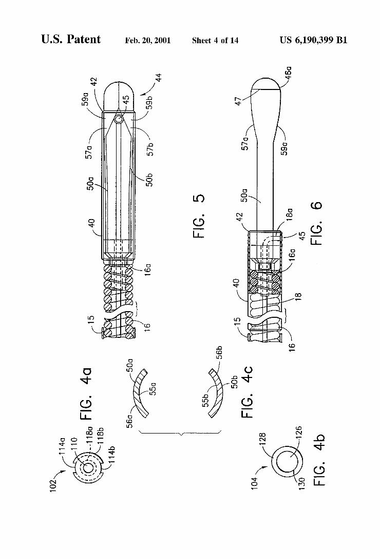
Turning noW to FIGS. 2 through 6, the end effector portion 14 includes a cylindrical sleeve 40, preferably hav ing a knife-sharp distal edge 42, and a jaW assembly 44. The
US 6,190,399 B1 7
jaW assembly 44 includes a pair of end effectors 44a, 44b, a screW 102, and a Washer or retaining sleeve 104. Each end effector 44a, 44b includes a jaW cup 46a, 46b preferably having a knife-sharp rim 48a, 48b (or radially arranged teeth as described in detail below), and a resilient, preferably narroW, arm 50a, 50b Which extends proximally from the jaW cup 46a, 46b. The narroW arm 50a, 50b, at its proximal end 51a, 51b, preferably includes a sharply descending angled portion 52a, 52b, and a gently angled portion 53a, 53b. At least the gently angled portion 53a, 53b of the arms 50a, 50b, and preferably the entire arms 50a, 50b are formed from super-elastic memory metal such as Nitinol (nickel titanium alloy), and are biased apart from each other (due to angled portions 53a, 53b of the arms 50a, 50b), thereby urging the jaW cups 46a, 46b apart (as seen in FIG. 2). In addition, as the arms 50a, 50b and the jaWs 46a, 46b are preferably integral With each other, the jaWs are preferably formed from a super-elastic or shape metal. HoWever, it should be appreciated that While it is preferable to form the entire arm and jaW from a super-elastic or shape memory metal, the jaW cups 46a, 46b and proximal ends 51a—b, 51a—b of the jaWs 44 may be made of any other material and attached to the resilient arms 50a, 50b by any conventional and appropriate means.
According to the ?rst embodiment of the invention, the proximal end 51a, 51b of each arm 50a, 50b is coupled to the distal end 16a of the coil 16 by crimping/locking With a holloW threaded screW 102 and a Washer 104 as best illustrated in FIGS. 3 and 4. The threaded screW 102 is substantially cylindrical, and generally includes a head por tion 106, a threaded portion 108, and a cylindrical through bore 110 along its central axis. The throughbore 110 is dimensioned to receive and alloW lateral movement of the control Wire 18. The distal end 112 of the head portion 106 has a diameter substantially equal to that of the outer diameter of the coil 16, and is provided With tWo opposing grooves 114a, 114b (see FIG. 4a) on the outer perimeter of the distal end 112 of the head portion 106. Grooves 114a, 114b are dimensioned to receive the angled portion 52a, 52b at the proximal end 51a, 51b of each of the narroW arms 50a, 50b. The proximal end 116 of the head portion 106 is shaped as a truncated cone (i.e., frustroconical) and has a larger diameter 118b at the distal end 112 of the head portion 106 and a smaller diameter 118a at the distal end 120 of the threaded portion 108. The threaded portion 108 has a diameter substantially equal to the inner diameter of the coil 16 and the proximal end 122 of the threaded portion 108 includes threads 124 for lockingly engaging the interior of the distal end 16a of the coil 16.
The Washer 104 is substantially cylindrical, and generally includes a throughbore 126 having proximal 128 and distal 130 sections. The distal section 128 of the throughbore 126 is shaped as a truncated cone, and the proximal section 130 extends therefrom. It Will be appreciated that the through bore 126 of the Washer 104 has substantially the same con?guration as the proximal end 116 of the head portion 106 of the screW 102 and distal end 120 of the threaded portion 108 of the screW 102. It Will noW be understood that the throughbore 126 of the Washer 104 is dimensioned for engaging the proximal end 116 of the head portion 106 of the screW 102 and distal end 125 of the threaded portion 108 of the screW 102 When the stepped 52a, 52b proximal ends 51a, 51b of the narroW arms 50a, 50b are positioned about the grooves 114a—b of the threaded screW 102 as described above. The proximal end 120 of the threaded portion 108 of the threaded screW 102 is then threaded into the interior of the distal end 16a of the coil 16. As can be seen in FIGS. 2
15
25
35
45
55
65
8 and 3, the Washer 104 is fastened betWeen the head portion 106 of the threaded screW 102 and the distal end 16a of the coil 16. The stepped 52a, 52b proximal ends 51a, 51b of the narroW arms 50a, 50b are thus fastened betWeen the Washer 104 and the threaded screW 102. As can be seen in FIG. 4c, the preferred end effector arms
50a, 50b have a substantially arced shape in cross section With inner and outer curved Walls 55a, 55b, 56a, 56b. It Will be appreciated that the arced shape of the arms extends the length of the narroW arms from the jaWs 44a, 44b, back to the angled proximal portions 52a, 52b. With this arrangement, the tube 40 Will slide easily over the arms as Will be described hereinafter. In addition, the angled proxi mal portions 52a, 52b of the jaWs 44a, 44b matingly engage the grooves 114a, 114b (see FIG. 4a) on the outer perimeter of the distal end 112 of the threaded screW 102 head portion 106.
Referring to FIGS. 2, 5 and 6, it Will be seen that the cylindrical sleeve 40 is coupled to the distal end of the control Wire 18 by providing the sleeve 40 With a lateral hole 45 Which engages a bent end 18a of the control Wire 18. As illustrated, the bent end 18a of the control Wire 18 is Welded to the hole 45 in the side of the sleeve 40. HoWever, as Will be described in detail hereinbeloW, other methods of cou pling the control Wire to the sleeve are possible. The cylindrical sleeve 40 is slidably mounted over the cylindrical Washer 104 and head portion 106 of the threaded screW 102, and is axially movable over the arced resilient arms 50a, 50b, thereby bending the arms at the gently bent locations 53a, 53b, and closing the jaWs 46a, 46b as shoWn in FIG. 5. As the resilient arms 50a, 50b are made of superelastic metal, they Will immediately return to their original open position (FIG. 2) once the cylinder sleeve 40 is retracted. Furthermore, even after repeatedly sliding the cylinder sleeve 40 back and forth over the arms 50a, 50b, the jaW assembly 44 Will maintain its original shape due to the above described properties of the superelastic metal. As seen in FIG. 6, the jaW cups 46a, 46b have an
eccentric, albeit symmetrical outline With their Widest point indicated by the line 47. Distal of the line 47, the jaW cups are substantially hemispherical and proximal of the line 47, the jaW cups are substantially hemi-elliptical. The jaW cups are arranged so that the rims are substantially aligned When closed as shoWn in FIG. 5. It Will also be seen from FIGS. 5 and 6 that the side Walls 57, 57b, 59a, 59b of the jaW cups 46a, 46b taper toWards the arms 50a, 50b to provide a smooth transition from the jaW cups to the arms. From the foregoing description and With reference to
FIGS. 1 through 6, those skilled in the art Will appreciate that When the spool 22 and the shaft 20 are axially displaced relative to each other, the cylindrical sleeve 40 and the end effectors 44a, 44b are similarly axially displaced relative to each other, from the positions shoWn in FIG. 2 to the positions shoWn in FIG. 5 and vice versa. When the spool 22 and shaft 20 are in the approximate position shoWn in FIG. 1, the cylindrical sleeve 40 and the end effectors 44a, 44b Will be in the approximate position shoWn in FIG. 2; i.e., With the jaWs open. Thus, When the spool 22 is moved toWards the thumb ring 24, or vice versa, the cylindrical sleeve 40 and the end effectors 44a, 44b Will be brought into the approximate position shoWn in FIG. 4; i.e., With the jaWs closed. Moreover, it Will also be appreciated that it is preferable to move the thumb ring 24 relative to the spool 22, rather than vice versa since that Will move the cylindrical sleeve 40 relative to the end effectors 44a, 44b rather than vice versa. This is desirable so that the end effectors are not moved aWay from a tissue sample While the jaWs are being closed.


