super mops - pixelbanane
TRANSCRIPT

superMOPSpro Copyright JUMPtec Industrielle Computertechnik AG Page: 1 of 93
superMOPSpro
Technical Manual
Rev. 2.2
JUMPtec
Industrielle Computertechnik AGBrunnwiesenstraße 1694469 Deggendorf/ Germany
PN of Manual: 96035-0003-00-0Manual Rev.: 2.2File: P487m222.DOC

Table of Contents
superMOPSpro Copyright JUMPtec Industrielle Computertechnik AG Page: 2 of 93
Table of Contents
Table of Contents ............................................................................................................................2
User Information ..............................................................................................................................4Trademarks ...........................................................................................................................4General .................................................................................................................................4Warranty................................................................................................................................5
Introduction......................................................................................................................................6superMOPSpro ......................................................................................................................6Features ................................................................................................................................6
Connector Overview ........................................................................................................................9Block Diagram .......................................................................................................................9Connector Arrangement.........................................................................................................10Connector Tables ..................................................................................................................11
Memory and I/O Information............................................................................................................12Memory Map .........................................................................................................................12I/O Map .................................................................................................................................15Interrupts ...............................................................................................................................16DMA ......................................................................................................................................16
Working with the superMOPSpro ...................................................................................................17Introduction............................................................................................................................17Description of the RTC - CMOS-Setup Menu.........................................................................18Description of superMOPSpro Extended Setup......................................................................24Up-/Downgrading a SDisk DIMM Module ...............................................................................27Restrictions of SDisk Usage...................................................................................................27Watchdog User Interface .......................................................................................................28
Peripheral Interfaces........................................................................................................................29DC Power Connector (X3)......................................................................................................29Keyboard, Reset, Battery, Speaker (X9).................................................................................29Parallel Port (X6) ...................................................................................................................31Serial Ports (X7,X8) ...............................................................................................................32Floppy Connector (X4)...........................................................................................................35IDE Connector for 2,5" Hard Disk (X10) .................................................................................35Feature Connector (X5) .........................................................................................................36Ethernet Connector (X11) ......................................................................................................37RS485 Option ........................................................................................................................37IRDA interface .......................................................................................................................38I2C-Bus ..................................................................................................................................38
The JIDA (JUMPtec Intelligent Device Architecture) Standard......................................................40
Network Operation...........................................................................................................................46Overview ...............................................................................................................................46Installation .............................................................................................................................48Diagnostics Overview ............................................................................................................68Technical Support..................................................................................................................72Setup Utility ...........................................................................................................................74
Specifications ..................................................................................................................................76Mechanical Specifications......................................................................................................76Physical Dimensions..............................................................................................................76Electrical Specifications.........................................................................................................77Environmental Specifications.................................................................................................77PC/104-Bus Specification of superMOPS ..............................................................................78
Signal Description ...........................................................................................................................81PC/104 Overview ..................................................................................................................81Address / Data Signal Group..................................................................................................81

Table of Contents
superMOPSpro Copyright JUMPtec Industrielle Computertechnik AG Page: 3 of 93
Control Signal Group .............................................................................................................82Special Function Signal Group...............................................................................................84Data Conversion and Swapping.............................................................................................86DMA Timing Specification .....................................................................................................89Bus-Master Exchange Operation ...........................................................................................90REFRESH* Signal Timing .....................................................................................................90
PC/104 Stack Characteristics ..........................................................................................................91Mechanical dimensions of standard PC/104 modules ............................................................91Self stacking system (Standard) with superMOPSpro ............................................................92Customized System with superMOPSpro...............................................................................92
History ..............................................................................................................................................93
User Information
superMOPSpro Copyright JUMPtec Industrielle Computertechnik AG Page: 4 of 93
User Information
Copyright 1996 JUMPtec Industrielle Computertechnik GmbH.In this document JUMPtec Industrielle Computertechnik GmbH will also be referred to by the shortform "JUMPtec".
The information in this document has been carefully checked and is believed to be accurate andreliable. However, no responsibility is assumed for inaccuracies. Furthermore, JUMPtec reserves theright to make changes to any portion of this manual to improve reliability, function or design.JUMPtec does not assume any liability for any product or circuit described herein.
Trademarks
AT and IBM are trademarks of International Business MachinesXT, AT, PS/2 and Personal System/2 are trademarks of International Business Machines Corporation.Microsoft is a registered trademark of Microsoft Corporation.Intel is a registered trademark of Intel Corporation.All other products and trademarks mentioned in this manual are trademarks of their respectiveowners.
The reproduction, transmission or use of this document or its contents is not permitted withoutexpressed written authority.Offenders will be liable for damages. All rights created by patent grant or registration of a utility modelor design, are reserved.(C) JUMPtec GmbH 1993
General
For the circuits, descriptions and tables indicated no responsibility is assumed as far as patents orother rights of third parties are concerned.The information in the Technical Descriptions describes the type of the boards and shall not beconsidered as assured characteristics.The reproduction, transmission or use of this document or its contents is not permitted withoutexpress written authority. Offenders will be liable for damages. All rights, including rights created bypatent grant or registration of a utility model or design, are reserved.

User Information
superMOPSpro Copyright JUMPtec Industrielle Computertechnik AG Page: 5 of 93
Warranty
Each board is carefully and thoroughly tested before being shipped. If, however, problems shouldoccur during the operation, please check your user specific settings of all boards included in yoursystem. This is often the source of the fault. If a board is defective, it can be sent to your supplier forrepair. Please take care of the following steps:
1. The board returned should correspond to the factory default settings since a test isonly possible under this settings.
2. Upon receipt of the board, please be aware that your user specific settings couldhave been changed during the repair and tests.
Within the guarantee, the repair is free as long as the guarantee conditions were kept. If no fault hasbeen found, you will be charged with the test cost due to the high test expenditure. Repairs outsidethe guarantee period will be charged.
This JUMPtec product is warranted against defects in material and workmanship for our guaranteedwarranty period from the date of shipment. During the warranty period, JUMPtec will, at its option,either repair or replace products which prove to be defective.
For warranty service or repair, the product must be returned to a service facility designated byJUMPtec.
The foregoing warranty shall not apply to defects resulting from improper or inadequate maintenanceor handling by the customer, unauthorized modification or misuse, operation outside of theenvironmental specifications for the product, or improper installation or maintenance.
JUMPtec will not be responsible for any defects or damages due to a faulty JUMPtec product otherthan the products supplied by JUMPtec.

Introduction
superMOPSpro Copyright JUMPtec Industrielle Computertechnik AG Page: 6 of 93
Introduction
superMOPSpro
The superMOPSpro integrates the complete functionality of an 80486 SX/DX motherboard with CPU,System-BIOS, 4 Mbyte to 20MByte DRAM, keyboard-controller, real time clock and additionalperipheral functions like COM1, COM2, LPT1, floppy-interface, IDE-harddisk-interface, watchdog,silicon disk and Ethernet access. The system runs with CPU clock speeds from 33MHz to 133MHz(” DX5” ). The superMOPSpro incorporates the following features:
Features
Supported Processors
Type Internal Clock Notes
80486SX, 33 MHz many 486 processor types are or
80486DX 33 MHz will be not be available anymore
80486DX2-66 66 MHz in the future
80486DX4-100 100 MHz
80486DX5-133 133 MHz
Memory Configurations, onboard and additional S.O.DIMM
Onboard S.O.DIMM Total
4 MB - 4 MB
4 MB 4 MB 8 MB
4 MB 16 MB 20 MB
for self-upgrade only use modules with:
support of fast page mode, no EDO-DRAM
one page mode (no 8 MB modules)
DRAMs with support of CAS only refresh
5V-modules (no 3.3V types)
(refer also to JUMPtec specification X00560.DOC)

Introduction
superMOPSpro Copyright JUMPtec Industrielle Computertechnik AG Page: 7 of 93
Silicon Disk as a BIOS Compatible Bootable Hard Disk
Onboard SDISK-DIMM Total
0.9 MB - 0.9 MB
0.9 MB 1 MB 1.9 MB
0.9 MB 2 MB 2.9 MB
0.9 MB 4 MB 4.9 MB
0.9 MB 8 MB 8.9 MB
Serial Ports, COMA and COMB (user configurable)
Base Adresses Port Definition
220h user
228h user
238h user
2E0h user
2E8h COM4
2F8 COM2
338 user
3E8 COM3
3F8 COM1
Parallel Port, LPT uni- or bi-directional (user configurable)
Base Adresses Port Definition
278
378
3BC
Floppy-Interface
via a flat foil connector
Standard IDE-Hard Disk-Interface
via a 2mm 44 pin 2.5” hard disk connector
Watchdog
implemented in the extended BIOS
FLASH-BIOS (AMI)

Introduction
superMOPSpro Copyright JUMPtec Industrielle Computertechnik AG Page: 8 of 93
Real Time Clock
Keyboard-Controller
EEPROM for CMOS-SETUP
IRDA-Support
I²C-Bus Interface
Ethernet 10BaseT (Twisted Pair)
RS485 prepared
PC/104-Format
90 * 95 mm (4,5" x 3,7") with the PC/104 Bus
5V only power supply
Full ISA electrical characteristics like timing and DC-characteristics
Low power CMOS technology with 12mA driver capacity (=half of ISA-bus)

Connector Overview
superMOPSpro Copyright JUMPtec Industrielle Computertechnik AG Page: 9 of 93
Connector Overview
Block Diagram
VLSIChipset
Watchdog
SMCI/O-Controller
80486SXto
AMD 5x86
Silicon Disk
DynamicRAM
Keyboard
Real TimeClock
SerialCOM A
SerialCOM B
ParallelLPT
FloppyInterface
HarddiskInterface
PC/104Bus
Ethernet

Connector Overview
superMOPSpro Copyright JUMPtec Industrielle Computertechnik AG Page: 10 of 93
Connector Arrangement
FLOPPY FEATURE
COM A
LPT
KBD
COM B
IDE
Ethernet
POWER PC/104
S.O.DIMM
The pin 1 of any connector is marked with a rectangular pad at the bottom side of the board and witha mark of the same kind in this drawing (showing the top view of the board).
The S.O.DIMM socket for memory and BIOS compatible flash disk consists of two ” slots” . The lowerone is for upgrade of memory. The upper one is only for flash disk usage.

Connector Overview
superMOPSpro Copyright JUMPtec Industrielle Computertechnik AG Page: 11 of 93
Connector Tables
Pin (A)PC/104
(B)PC/104
(C)PC/104
(D)PC/104
Power IDE Floppy LPT COMA COMB Key Feature Network
0 GND GND1 /IOCHCK GND /SBHE /MEMCS16 GND /RESET VCC /STB RLSD1 RLSD2 SPKR ISPDEV TXD+2 SD7 RESETDRV LA23 /IOCS16 VCC GND IDX /AFD DSR1 DSR2 GND RAMWI TXD-3 SD6 VCC LA22 IRQ10 keypin IDE D7 VCC PD0 SIN1 SIN2 POWERGOOD /HDLED RXD+4 SD5 IRQ9 LA21 IRQ11 +12V IDE D8 DS0 /ERR RTS1 RTS2 /KLOCK VCC NC5 SD4 -5V LA20 IRQ12 -5V IDE D6 VCC PD1 SOUT1 SOUT2 KDATA MDATA NC6 SD3 DRQ2 LA19 IRQ15 -12V IDE D9 /DCHNG /INIT CTS1 CTS2 KCLK VCC RXD-7 SD2 -12V LA18 IRQ14 GND IDE D5 NC PD2 DTR1 DTR2 GND MCLK NC8 SD1 /0WS LA17 /DACK0 VCC IDE D10 NC /SLIN RI1 RI2 VCC GND NC9 SD0 +12V /MEMR DRQ0 IDE D4 NC PD3 GND GND VBAT /RLSDB10 IOCHRDY GND1) /MEMW /DACK5 IDE D11 Mo0 GND VCC VCC POWERGOOD /DSRB11 AEN /SMEMW SD8 DRQ5 IDE D3 NC PD4 SINB12 SA19 /SMEMR SD9 /DACK6 IDE D12 DIR GND /RTSB13 SA18 /IOW SD10 DRQ6 IDE D2 NC PD5 SOUTB14 SA17 /IOR SD11 /DACK7 IDE D13 STEP GND /CTSB15 SA16 /DACK3 SD12 DRQ7 IDE D1 GND PD6 /DTRB16 SA15 DRQ3 SD13 VCC IDE D14 WD GND /RIB17 SA14 /DACK1 SD14 /MASTER IDE D0 GND PD7 GND18 SA13 DRQ1 SD15 GND IDE D15 WG GND LKLED19 SA12 /REFRESH GND GND1) GND GND /ACK /EN20 SA11 SYSCLK NC TR00 GND VCC21 SA10 IRQ7 NC GND BUSY I2DAT22 SA9 IRQ6 GND WP GND VCC23 SA8 IRQ5 /IOW GND PE I2CLK24 SA7 IRQ4 GND RD GND GND25 SA6 IRQ3 /IOR GND SLCT Powergood26 SA5 /DACK2 GND SIDE VCC LNLED27 SA4 T/C NC28 SA3 BALE BALE29 SA2 VCC NC30 SA1 OSC GND31 SA0 GND IRQ1432 GND GND /IOCS1633 SA134 NC35 SA036 SA237 /IDE CS038 /IDE CS139 /HDLED40 GND41 VCC42 VCC43 GND44 NC
1) these pins are connected to GND, while in PC/104 specification they are keypins.
The superMOPSpro is designed in the standard PC/104 format.The PC/104 bus consist of 2 different connectors with 104 pins in total.- XT bus connector (64 pins)- AT bus connector (40 pins) (Optional for 16 bit data bus system)
The pinout of the PC/104 bus connectors correspond to the pinout of the ISA bus connectors withsome added ground lines. Therefore the two PC systems with different form factor are electricallycompatible.
The XT bus connector is labeled X1 with row A and B.The corresponding 64 pin stackthrough header (ISA bus = 62 pins) has two added ground pins at theend of the connector (pin A32 and pin B32). Therefore the pinout between PC/104 bus and XT ISAbus is identical between A1 - A31 and B1 - B31.
The AT bus extension connector is labeled X2 with row C and D.The corresponding 40 pin stackthrough header (ISA bus = 36 pins) has four added ground pins, twoon each side of the connector. In order to avoid any confusion the first two pins are defined as pin C0and pin D0. The additional ground pins at the end of the connector are defined as C19 and D19.Therefore the pinout between PC/104 bus and AT ISA bus is again identical between C1 - C18 andD1 - D18.

Memory and I/O Information
superMOPSpro Copyright JUMPtec Industrielle Computertechnik AG Page: 12 of 93
Memory and I/O Information
Memory Map
The 24 address lines of the superMOPSpro processor module can address up to 32MByte ofmemory. Onboard DRAM can be up to 32MByte, too (end address 01FFFFFFh). The first 640KByteof DRAM are used as main memory.DOS allows to address 1MByte directly. The memory area above 1MByte (high memory, extendedmemory) is accessed under DOS via special drivers like HIMEM.SYS, EMM386.EXE etc. Otheroperating systems (OS/2, Windows-NT) allow to address the full memory area directly.
Standard Memory Map
000000h +-------------------+ - ¦ Interruptvectors ¦ ¦ 640KByte ¦ BIOS-variables ¦ ¦ of ¦ IO.SYS, MSDOS.SYS ¦ ¦ main memory ¦ COMMAND.COM ¦ ¦ ¦ Applications ¦ ¦0A0000h +-------------------¦ + ¦ EGA/VGA Video- ¦ ¦ ¦ Adapter ¦ ¦ upper memory0B0000h +-------------------¦ ¦ area ¦ MGA/CGA Video- ¦ ¦ (RAM areas not ¦ Adapter ¦ ¦ used by video0C0000h +-------------------¦ ¦ cards can be - ¦ VGA BIOS ¦ ¦ used otherwise) ¦ 64KByte0C8000h +-------------------¦ ¦ ¦ Shadow RAM ¦ BIOS-extensions ¦ ¦ (all not used - ¦ Shadow-RAM ¦ ¦ areas could be ¦ Dual port RAM ¦ ¦ used otherwise) ¦ etc. ¦ ¦0F0000h +-------------------¦ ¦ - ¦ System-Setup ¦ ¦ ¦ 64KByte ¦ System-BIOS ¦ ¦ ¦ Shadow RAM100000h +-------------------¦ + - ¦ ¦ ¦ higher memory area110000h +-------------------¦ + ¦ ¦ ¦ extended or ¦ ¦ ¦ expanded memoryFF0000h +-------------------¦ - ¦ System-Setup+BIOS ¦ ¦ duplicated ¦ +-------------------+

Memory and I/O Information
superMOPSpro Copyright JUMPtec Industrielle Computertechnik AG Page: 13 of 93
Expanded Memory Map
The user can convert (up to 20Mbytes) Extended Memory into Expanded Memory (EMS). Theselected Expanded Memory is devided into 16KByte pages, of which four can be mapped into theEMS-frame. The EMS-frame is located within the first 1MByte address space and has a length of64KByte. The start address of the EMS-page can be selected between C8000h and E0000h in stepsof 16KBytes. Most Expanded Memory Managers are choosing their frame address location bythemselves if it is not explicit set..
000000h +-------------------+ - ¦ Interruptvectors ¦ ¦ 640KByte ¦ BIOS-variables ¦ ¦ of ¦ IO.SYS, MSDOS.SYS ¦ ¦ main memory ¦ COMMAND.COM ¦ ¦ ¦ HIMEM, EMM386 ¦ ¦ ¦ Applications ¦ ¦0A0000h +-------------------¦ + ¦ EGA/VGA Video- ¦ ¦ ¦ Adapter ¦ ¦ upper memory0B0000h +-------------------¦ ¦ area ¦ MGA/CGA Video- ¦ ¦ (RAM areas not ¦ Adapter ¦ ¦ used by video0C0000h +-------------------¦ ¦ cards can be - ¦ VGA BIOS ¦ ¦ used otherwise) ¦ 64KByte0C8000h +-------------------¦ ¦ ¦ Shadow RAM ¦ BIOS-extensions ¦ ¦ (all not used - ¦ Shadow-RAM ¦ ¦ areas could be ¦ Dual port RAM ¦ ¦ used otherwise) ¦ EMS-Pages ¦ ¦ ¦ etc. ¦ ¦0F0000h +-------------------¦ ¦ - ¦ System-Setup ¦ ¦ ¦ 64KByte ¦ System-BIOS ¦ ¦ ¦ Shadow RAM100000h +-------------------¦ + - ¦ ¦ ¦ higher memory area110000h +-------------------¦ + ¦ ¦ ¦ extended or ¦ ¦ ¦ expanded memoryFF0000h +-------------------¦ - ¦ System-Setup+BIOS ¦ ¦ duplicated ¦ +-------------------+
To be able to work with Expanded Memory under MS-DOS, you have to add the following drivers toyour CONFIG.SYS:
HIMEM.SYS and EMM386.EXE
The superMOPSpro uses a 32KByte extension BIOS (many other boards do this, too) which ismapped to a configurable memory area. Some other kind of boards have no extension BIOS, but areusing drivers which communicate with their corresponding devices via memory mapped I/O. All theseboards have one thing in common, they have to share the upper memory area with the ExpandedMemory Manager. This is often the reason for several problems in the system. Make sure youexcluded all areas in the upper memory, which are used by extension BIOSes and memory mappedI/O. Your instruction in the CONFIG.SYS concerning the Expanded Memory Manager should look likethis: (questionmarks for location of extension BIOS)
DEVICE=EMM386.EXE X=????-???? X=F000-FFFF

Memory and I/O Information
superMOPSpro Copyright JUMPtec Industrielle Computertechnik AG Page: 14 of 93
Example for Memory Map
Assume you’ve got a system consisting of a superMOPSpro, a graphic module PC/104-VGALCD-4and a special digital I/O-board. The graphic-module PC/104-VGALCD-4 is a product of JUMPtec andhas an extension BIOS located at C800h to CBFFh while the digital I/O-board uses a memory windowfrom D800h to DC00h for memory mapped I/O. To avoid any BIOS conflict you have to choose alocation for the superMOPSpro extension BIOS (32KByte) at either D000h or above of D800h.Assume your decision was D000h. The special systems memory map would look like this:
000000h +-------------------+ - ¦ Interruptvectors ¦ ¦ ¦ BIOS-variables ¦ ¦ ¦ IO.SYS, MSDOS.SYS ¦ ¦ 640KByte of main memory ¦ COMMAND.COM ¦ ¦ ¦ HIMEM, EMM386 ¦ ¦ ¦ Applications ¦ ¦0A0000h +-------------------¦ + ¦ EGA/VGA Video- ¦ ¦ used by PC/104-VGALCD-4 ¦ Adapter ¦ ¦0B0000h +-------------------¦ + ¦ CGA/MGA Video- ¦ ¦ available in some VGA-modes ¦ Adapter ¦ ¦0C0000h +-------------------¦ + ¦ VGA BIOS ¦ ¦ VGA-BIOS of PC/104-VGALCD-40C8000h +-------------------¦ + ¦ VGA ext. BIOS ¦ ¦ Ext. BIOS of PC/104-VGALCD-4 0D0000h +-------------------¦ + ¦ superMOPSpro ¦ ¦ Ext. BIOS of the superMOPSpro ¦ extension BIOS ¦ ¦ for handling of SDisk, etc.0D8000h +-------------------¦ + ¦ Digital I/O ¦ ¦ Area for memory mapped I/O of ¦ ¦ ¦ special digital I/O-board0DC000h +-------------------¦ + ¦ ¦ ¦ free ¦ ¦ ¦0F0000h +-------------------¦ + ¦ System-Setup ¦ ¦ ¦ System-BIOS ¦ ¦100000h +-------------------¦ + ¦ ¦ ¦110000h +-------------------¦ + ¦ ¦ ¦ extended or ¦ ¦ ¦ expanded memoryFF0000h +-------------------¦ - ¦ System-Setup+BIOS ¦ ¦ duplicated ¦ +-------------------+
If you want to use the EMM386.EXE with this configuration, your CONFIG.SYS would have to holdthe following instruction:
DEVICE=EMM386.EXE X=C800-CC00 X=D000-D800 X=D800-DC00 X=F000-FFFF
or in a shorter way:
DEVICE=EMM386.EXE X=C800-DC00 X=F000-FFFF
The EMM386.EXE will after a reboot choose a frame above DC000h for his own purposes and leavethe excluded areas untouched.
Note, that while booting up your system with this configuration the exclusion of area F000 to FFFF willcause the following or a similar warning : ” Bereiche überlappen sich...” .We asked MICROSOFT about this EMM386 warning and got the information, that this message willalways appear, when the F000-segment lies in the shadow RAM. This is a bug of the EMM386 andnot of the superMOPSpro.

Memory and I/O Information
superMOPSpro Copyright JUMPtec Industrielle Computertechnik AG Page: 15 of 93
I/O Map
The I/O port addresses of the processor modules superMOPSpro are functionally identical with astandard PC/AT.An additional I/O-port is the GPCS, which has the standard location 0050h. This port is decoded onlywith 10 bits, therefore some adresses of the I/O-address space can´t be used because of mirroring.The mirroring will occur every 400h starting at 450h, 850h etc.
I/O addresses superMOPSpro-used function0000 - 000F fixed DMA-controller 10020 - 003F fixed interrupt-controller 10040 - 0043 fixed counter/timer0050 - 005F fixed GPCS-Port0060 - 0064 fixed keyboard-controller0070 - 0071 fixed real time clock0080 - 008F fixed DMA page register 74LS6120092 fixed port A register (Fast A20 Gate)00A0 - 00BF fixed interrupt-controller 200C0 - 00DE fixed DMA-controller 200EC - 00EF fixed configuration registers00F0 - 00FF fixed math-co-processor01F0 - 01F8 fixed fixed disk0220 - 0227 if configured instead
other serialuser specific serial port
0228 - 022F if configured insteadother serial
user specific serial port
0238 - 023F if configured insteadother serial
user specific serial port
02E0 - 02E7 if configured insteadother serial
user specific serial port
0278 - 027F if configured insteadparallel 1
parallel port 2
02E8 - 2EF if configured insteadother serial
user specific serial port (COM4)
02F8 - 02FF default serial port 20300 - 031F default if equipped
with EthernetEthernet Controller
0378 - 037F default parallel port 103E8 - 3EF if configured instead
other serialuser specific serial port (COM3)
03F0 - 03F7 x diskette controller03F8 - 03FF default serial port 10450 - 045F , 0850 - 085F0C50 - 0C5F , 1050 - 105F1450 - 145F , etc.
x mirroring of GPCS port over the wholeI/O address space (every 400h)

Memory and I/O Information
superMOPSpro Copyright JUMPtec Industrielle Computertechnik AG Page: 16 of 93
Interrupts
IRQ0 system timerIRQ1 keyboardIRQ2 cascadeIRQ3 COM 2IRQ4 COM 1IRQ5 availableIRQ6 floppyIRQ7 LPT 1IRQ8 clock/ calendarIRQ9 available
IRQ10 availableIRQ11 availableIRQ12 availableIRQ13 numeric-processorIRQ14 hard diskIRQ15 available
Please note that JUMPtec PC/104 devices are designed following the P996 Specification for ISA-Systems. Due to this fact shareable interrupts are not supported. Some PC/104 manufacturers are notfollowing the P996 Specification and allow shareable interrupts. If you want to use such a PC/104board with JUMPtec devices, contact the manufacturer of the board and ask for a possibility toswitch of interrupt sharing.
DMA
DMA 0 availableDMA 1 availableDMA 2 floppyDMA 3 availableDMA 4 cascadeDMA 5 availableDMA 6 availableDMA 7 available

Working with the superMOPSpro
superMOPSpro Copyright JUMPtec Industrielle Computertechnik AG Page: 17 of 93
Working with the superMOPSpro
Introduction
Before you can work with your superMOPSpro you have to configure your system. All the features ofthe superMOPSpro are fully software configurable, so you don’t have to place any Jumpers and it ispossible to simply plug this board into your system and turn power on. Nevertheless the softwareconfiguration has to be taken with care to avoid malfunction.
With power up or keyboard reset the system starts up with the POST (Power On Self Test) and atleast the following reports will appear on the screen:
VGA-BIOS Report
This report depends of the video controller you use in your system. Some video controllers evendisplay no reports or have the possibility to suppress their own messages. Check the manual of yourgraphic controller board which message should be displayed.
superMOPSpro System BIOS Report
The superMOPSpro has a system BIOS based on a source code from American Megatrend Inc.which will give you a report similar to the following text.
AMIBIOS (C) 1992 American Megatrends Inc.,SuperMOPS Pro V?.? (with ?.? holding the system BIOS revision)
Wait ......
Before the WAIT message is displayed a memory test may be conducted when the system boots upafter a hardware reset. Note that the system BIOS may give you the option do disable the memorytest on every boot up.
While the WAIT message is displayed the user has the possibility to press the <DEL> key to enter theRTC - CMOS setup.
SuperMOPSpro Extension BIOS Report
The Extension BIOS of the superMOPSpro is necessary to control the extended features of processorboard. It will display the following lines on the monitor.
Hostmode ...
SuperMOPS Pro Extension BIOS V?.? from zz/zz/zzChecking o.K.(with ?.? holding extension BIOS revision and zz/zz/zz showing revision date)
SuperMOPSpro Setup
While this message of the extension BIOS is displayed the user has the possibility to press the keycombination <ALT><F1> to enter the extended setup.
Working with the superMOPSpro
superMOPSpro Copyright JUMPtec Industrielle Computertechnik AG Page: 18 of 93
Further Reports
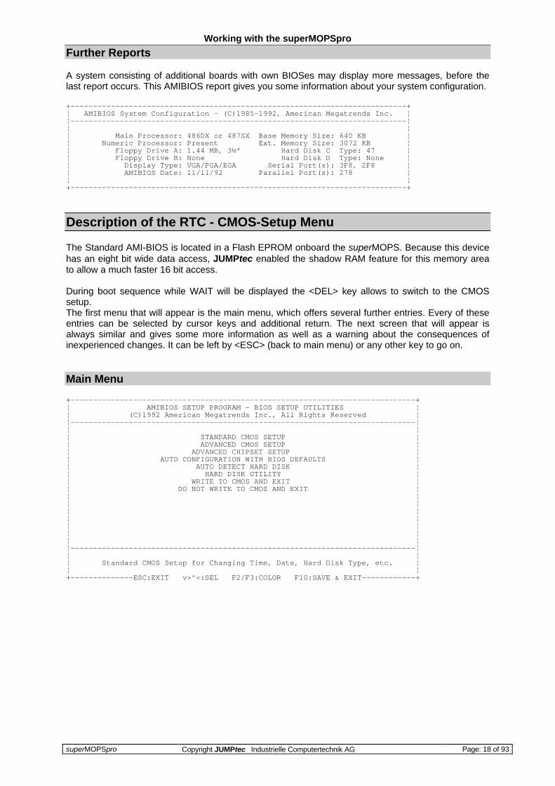
A system consisting of additional boards with own BIOSes may display more messages, before thelast report occurs. This AMIBIOS report gives you some information about your system configuration.
+---------------------------------------------------------------------------+¦ AMIBIOS System Configuration - (C)1985-1992, American Megatrends Inc. ¦¦---------------------------------------------------------------------------¦¦ ¦¦ Main Processor: 486DX or 487SX Base Memory Size: 640 KB ¦¦ Numeric Processor: Present Ext. Memory Size: 3072 KB ¦¦ Floppy Drive A: 1.44 MB, 3½" Hard Disk C Type: 47 ¦¦ Floppy Drive B: None Hard Disk D Type: None ¦¦ Display Type: VGA/PGA/EGA Serial Port(s): 3F8, 2F8 ¦¦ AMIBIOS Date: 11/11/92 Parallel Port(s): 278 ¦¦ ¦+---------------------------------------------------------------------------+
Description of the RTC - CMOS-Setup Menu
The Standard AMI-BIOS is located in a Flash EPROM onboard the superMOPS. Because this devicehas an eight bit wide data access, JUMPtec enabled the shadow RAM feature for this memory areato allow a much faster 16 bit access.
During boot sequence while WAIT will be displayed the <DEL> key allows to switch to the CMOSsetup.The first menu that will appear is the main menu, which offers several further entries. Every of theseentries can be selected by cursor keys and additional return. The next screen that will appear isalways similar and gives some more information as well as a warning about the consequences ofinexperienced changes. It can be left by <ESC> (back to main menu) or any other key to go on.
Main Menu
+-----------------------------------------------------------------------------+¦ AMIBIOS SETUP PROGRAM - BIOS SETUP UTILITIES ¦¦ (C)1992 American Megatrends Inc., All Rights Reserved ¦¦-----------------------------------------------------------------------------¦¦ ¦¦ STANDARD CMOS SETUP ¦¦ ADVANCED CMOS SETUP ¦¦ ADVANCED CHIPSET SETUP ¦¦ AUTO CONFIGURATION WITH BIOS DEFAULTS ¦¦ AUTO DETECT HARD DISK ¦¦ HARD DISK UTILITY ¦¦ WRITE TO CMOS AND EXIT ¦¦ DO NOT WRITE TO CMOS AND EXIT ¦¦ ¦¦ ¦¦ ¦¦ ¦¦ ¦¦ ¦¦ ¦¦-----------------------------------------------------------------------------¦¦ ¦¦ Standard CMOS Setup for Changing Time, Date, Hard Disk Type, etc. ¦¦ ¦+--------------ESC:EXIT v>^<:SEL F2/F3:COLOR F10:SAVE & EXIT------------+

Working with the superMOPSpro
superMOPSpro Copyright JUMPtec Industrielle Computertechnik AG Page: 19 of 93
Menu Item 1
+-----------------------------------------------------------------------------+¦ AMIBIOS SETUP PROGRAM - Standard CMOS Setup ¦¦ (C)1992 American Megatrends Inc., All Rights Reserved ¦¦-----------------------------------------------------------------------------¦¦ ¦¦ Date (mn/date/year): Tue, Jan 01 1980 Base Memory : 640 KB ¦¦ Time (hour/min/sec): 03 : 18 : 40 Ext. Memory : 3072 KB ¦¦ Cyln Head WPcom LZone Sect Size ¦¦ Hard Disk C: Type : 47 = USER TYPE 684 16 65535 684 38 203 ¦¦ Hard Disk D: Type : Not Installed ¦¦ Floppy Drive A: : 1.44 MB, 3½" +---------------------------¦¦ Floppy Drive B: : Not Installed ¦Sun¦Mon¦Tue¦Wed¦Thu¦Fri¦Sat¦¦ Primary Display : VGA/PGA/EGA ¦---+---+---+---+---+---+---¦¦ Keyboard : Installed ¦ 30¦ 31¦ 1¦ 2¦ 3¦ 4¦ 5¦¦ ¦---+---+---+---+---+---+---¦¦ ¦ 6¦ 7¦ 8¦ 9¦ 10¦ 11¦ 12¦¦ ¦---+---+---+---+---+---+---¦¦ +---------------------------------------------+ ¦ 13¦ 14¦ 15¦ 16¦ 17¦ 18¦ 19¦¦ ¦ Options:- ¦ ¦---+---+---+---+---+---+---¦¦ ¦ Installed : Test keyboard ¦ ¦ 20¦ 21¦ 22¦ 23¦ 24¦ 25¦ 26¦¦ ¦ Not Installed : Do not test keyboard ¦ ¦---+---+---+---+---+---+---¦¦ +---------------------------------------------+ ¦ 27¦ 28¦ 29¦ 30¦ 31¦ 1¦ 2¦¦ ¦---+---+---+---+---+---+---¦¦ ¦ 3¦ 4¦ 5¦ 6¦ 7¦ 8¦ 9¦+-ESC:EXIT v>^<:SEL F2/F3:COLOR PU/PD:Modify------------------------------+
Entry Function /Meaning additional note
Date set the actual CMOS date
Time set the actual CMOS time
Base Memory base memory size 1)
Ext. Memory extended memory size
Hard Disk C configure the first hard disk 2), 3), 4)
Hard Disk D configure the second hard disk
Floppy Drive A configure the first floppy drive
Floppy Drive B configure the second floppy drive
Primary Display configure primary display 5)
Keyboard enable/disable keyboard test 6)
notes: 1) the memory sizes should match with the installed RAM
2) don’t try to configure the onboard silicon disk here, this ispart of the extension setup
3) most hard disks don’t have to be configured manually here,try the ” Auto Detect Hard Disk” feature first
4) the superMOPSpro is only capable to handle hard disks with up to504MB; bigger ones can only be supported with specialhandlers, which are available on the free market
5) not necessary to be set
6) this function has no effect, because the system will boot even ifkeyboard is enabled and no keyboard is connected
Hard Disk Types

Working with the superMOPSpro
superMOPSpro Copyright JUMPtec Industrielle Computertechnik AG Page: 20 of 93
For the hard disk type either a set of parameters can be chosen from a list of 46 different standarddisk drives (see below) or by selecting type 47 a user defined set of parameters can be installed.
FIXED DISK CONFIGURATIONType Cyls Heads WPcom Ctrl Byte LZone Secs Size1 306 4 128 0 305 17 10 MB2 615 4 300 0 615 17 20 MB3 615 6 300 0 615 17 31 MB4 940 8 512 0 940 17 62 MB5 940 6 512 0 940 17 47 MB6 615 4 65535 0 615 17 20 MB7 462 8 256 0 511 17 31 MB8 733 5 65535 0 733 17 30 MB9 900 15 65535 8 901 17 112 MB10 820 3 65535 0 820 17 20 MB11 855 5 65535 0 855 17 35 MB12 855 7 65535 0 855 17 50 MB13 306 8 128 0 319 17 20 MB14 733 7 65535 0 733 17 43 MB15 0 0 0 0 0 0 0 MB16 612 4 0 0 663 17 20 MB17 977 5 300 0 977 17 41 MB18 977 7 65535 0 977 17 57 MB19 1024 7 512 0 1023 17 60 MB20 733 5 300 0 732 17 30 MB21 733 7 300 0 732 17 43 MB22 733 5 300 0 733 17 30 MB23 306 4 0 0 336 17 10 MB24 925 7 0 0 925 17 54 MB25 925 9 65535 8 925 17 69 MB26 754 7 754 0 754 17 44 MB27 754 11 65535 8 754 17 69 MB28 699 7 256 0 699 17 41 MB29 823 10 65535 8 823 17 68 MB30 918 7 918 0 918 17 53 MB31 1024 11 65535 8 1024 17 94 MB32 1024 15 65535 8 1024 17 128 MB33 1024 5 1024 0 1024 17 43 MB34 612 2 128 0 612 17 10 MB35 1024 9 65535 8 1024 17 77 MB36 1024 8 512 0 1024 17 68 MB37 615 8 128 0 615 17 41 MB38 987 3 987 0 987 17 25 MB39 987 7 987 0 987 17 57 MB40 820 6 820 0 820 17 41 MB41 977 5 977 0 977 17 41 MB42 981 5 981 0 981 17 41 MB43 830 7 512 0 830 17 48 MB44 830 10 65535 8 830 17 69 MB45 917 15 65535 8 918 17 114 MB46 1224 15 65535 8 1223 17 152 MB47 x x x x x x

Working with the superMOPSpro
superMOPSpro Copyright JUMPtec Industrielle Computertechnik AG Page: 21 of 93
Menu Item 2
+-----------------------------------------------------------------------------+¦ AMIBIOS SETUP PROGRAM - Advanced CMOS Setup ¦¦ (C)1992 American Megatrends Inc., All Rights Reserved ¦¦-----------------------------------------------------------------------------¦¦ ¦ ¦¦ Typematic Rate Programming : Enabled ¦ ¦¦ Typematic Rate Delay (msec): 500 ¦ ¦¦ Typematic Rate (Chars/Sec) : 30 ¦ ¦¦ Above 1 MB Memory Test : Disabled¦ ¦¦ Hit <DEL> Message Display : Enabled ¦ ¦¦ Wait For <F1> If Any Error : Enabled ¦ ¦¦ System Boot Up Num Lock : Off ¦ ¦¦ Floppy Drive Seek At Boot : Disabled¦ ¦¦ System Boot Up Sequence : C:, A: ¦ ¦¦ Video ROM Shadow : Enabled ¦ ¦¦ ¦ ¦¦ ¦ ¦¦ ¦ ¦¦ ¦ ¦¦ ¦ ¦¦ ¦ ¦¦ ¦ ¦¦-----------------------------------------------------------------------------¦¦---------ESC:Exit v>^<:SEL (Ctrl)Pu/Pd:Modify F1:Help F2/F3:Color--------¦+---------F5:Old Values F6:BIOS Setup Defaults F7:Power-On Defaults--------+
Entry Function /Meaning note
Typematic Rate Progr. enable/disable changing typematic rate
Typematic Rate Delay sets time after which repetition of a keystroke
will start with typematic rate
Typematic Rate sets the speed at which a keystroke is repeated
Above 1 MB Memory Test enable/disable memory test above 1 MB during
boot up
Hit <DEL> Message Display enable/disable this message during boot up
Wait for <F1> If Any Error enable/disable this message which appears
with a POST error during boot up
System Boot Up Num Lock enable/disable Num Lock Key
Floppy Drive Seek At Boot enable/disable a seek on floppy drive during
boot up
System Boot Up Sequence sets the boot up sequence to floppy or hard disk
as first device
Video ROM Shadow enable/disable shadowing of video ROM into
faster RAM

Working with the superMOPSpro
superMOPSpro Copyright JUMPtec Industrielle Computertechnik AG Page: 22 of 93
Menu Item 3
+-----------------------------------------------------------------------------+¦ AMIBIOS SETUP PROGRAM - Advanced Chipset Setup ¦¦ (C)1992 American Megatrends Inc., All Rights Reserved ¦¦-----------------------------------------------------------------------------¦¦ ¦ ¦¦ Middle BIOS : Disabled¦ ¦¦ Slow CPU Speed Emulation : /1 ¦ ¦¦ I/O Address Decode : 16 bit ¦ ¦¦ ¦ ¦¦ ¦ ¦¦ ¦ ¦¦ ¦ ¦¦ ¦ ¦¦ ¦ ¦¦ ¦ ¦¦ ¦ ¦¦ ¦ ¦¦ ¦ ¦¦ ¦ ¦¦ ¦ ¦¦ ¦ ¦¦ ¦ ¦¦-----------------------------------------------------------------------------¦¦---------ESC:Exit v>^<:SEL (Ctrl)Pu/Pd:Modify F1:Help F2/F3:Color--------¦+---------F5:Old Values F6:BIOS Setup Defaults F7:Power-On Defaults--------+
Entry Function /Meaning note
Middle BIOS. enable/disable mirroring of system BIOS at
E000h-EFFFh
1)
Slow CPU Speed Emulation without function on the superMOPSpro
I/O AddressDecode sets the speed at which a keystroke is repeated
notes: 1) should be left to disabled

Working with the superMOPSpro
superMOPSpro Copyright JUMPtec Industrielle Computertechnik AG Page: 23 of 93
Menu Item 4
” Auto Configuration with BIOS Defaults” will load default values from the ROM table. This is allwaysa very save configuration and may help with some BIOS problems.
Menu Item 5
+-----------------------------------------------------------------------------+¦ AMIBIOS SETUP PROGRAM - AUTO DETECT HARD DISK ¦¦ (C)1992 American Megatrends Inc., All Rights Reserved ¦¦-----------------------------------------------------------------------------¦¦ Cyln Head WPcom LZone Sect Size (MB) ¦¦ Hard Disk C: Type : 47=USER TYPE 684 16 65535 684 38 203 ¦¦ Hard Disk D: Type : Not Detected ¦¦ ¦¦ ¦¦ ¦¦ +------------------------------------+ ¦¦ ¦ ¦ ¦¦ ¦ Accept Parameters for D: (Y/N) ? N ¦ ¦¦ ¦ ¦ ¦¦ +------------------------------------+ ¦¦ ¦¦ ¦¦ ¦¦ ¦¦ ¦¦ ¦¦ ¦¦ ¦+--------------------------------ESC:EXIT-------------------------------------+
This menu item allows an autodetection of most hard disk types, however some older disks don’tsupport autodetection and have to be configured manually in menu item 1.Autodetection won’t configure the optional onboard silicon disk, this drive has to be configured in theextension setup described later in this manual.
Menu Item 6
” Hard Disk Utility” will only be described in a short way, because this menu item is only useful withold hard disk types. This feature makes a low level format and is not needed with today’s hard disks.JUMPtec gives the advice not to use this item except you’re sure about the consequences.
Menu Item 7
”Write To CMOS And Exit” leaves the AMIBIOS-SETUP and saves the actual settings in the flashEPROM.
Menu Item 8
” Do Not Write To CMOS And Exit” leaves the AMIBIOS-SETUP without saving the actual settings.Old settings will stay active.
Working with the superMOPSpro
superMOPSpro Copyright JUMPtec Industrielle Computertechnik AG Page: 24 of 93
Description of superMOPSpro Extended Setup
Supported functions
q Disk-management and disk-map of solid state disk
q Setup of onboard super-I/O-chip
q Setup of watchdog feature
q Battery voltage state
q Setup of extension- and user-BIOS
Entering and Configuering superMOPSpro Setup
During boot up immediately after checking the Solid State Disk the message ” SuperMOPS Pro-Setup” appears for 0,5s . While this moment the extended setup can be entered by pressing the
buttons <ALT><F1> simultaneously.
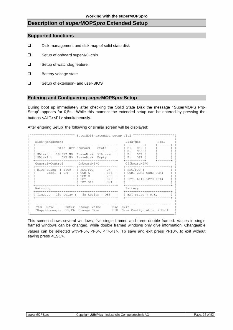
After entering Setup the following or similar screen will be displayed:
¦¯¯¯¯¯¯¯¯¯¯¯¯¯¯¯¯¯¯¯¯¯¯¯¯ SuperMOPS extended setup V1.2 ¯¯¯¯¯¯¯¯¯¯¯¯¯¯¯¯¯¯¯¯¯¯¦¦ ¦¦ Disk-Management Disk-Map Pool ¦¦ +-------------------------------------------+ +----------+ +-------+ ¦¦ ¦ Size WrP Command State ¦ ¦ C: HD0 ¦ ¦ ¦ ¦¦ ¦-------------------------------------------¦ ¦ D: SD0 ¦ ¦ ¦ ¦¦ ¦ SDisk0 : 1856KB NO EraseDisk 71% used ¦ ¦ E: OFF ¦ ¦ ¦ ¦¦ ¦ SDisk1 : 0KB NO EraseDisk Empty ¦ ¦ F: OFF ¦ ¦ ¦ ¦¦ +-------------------------------------------+ +----------+ +-------+ ¦¦ General-Control Onboard-I/O Offboard-I/O ¦¦ +--------------------+ +--------------------+ +------------------------+ ¦¦ ¦ BIOS SDisk : E000 ¦ ¦ HDC/FDC : ON ¦ ¦ HDC/FDC : ¦ ¦¦ ¦ User1 : OFF ¦ ¦ COM-A : 3F8 ¦ ¦ COM1 COM2 COM3 COM4 ¦ ¦¦ ¦ ¦ ¦ COM-B : 2F8 ¦ ¦ ¦ ¦¦ ¦ ¦ ¦ LPT : 378 ¦ ¦ LPT1 LPT2 LPT3 LPT4 ¦ ¦¦ ¦ ¦ ¦ LPT-DIR : UNI ¦ ¦ ¦ ¦¦ +--------------------+ +--------------------+ +------------------------+ ¦¦ Watchdog Battery ¦¦ +-------------------------------------------+ +------------------------+ ¦¦ ¦ Timeout : 15s Delay : 5s Action : OFF ¦ ¦ BAT state : o.K. ¦ ¦¦ +-------------------------------------------+ +------------------------+ ¦¦ ¦¦-----------------------------------------------------------------------------¦¦ ^v<> Move Enter Change Value Esc Exit ¦¦ PGup,PGdown,+,-,F5,F6 Change Size F10 Save Configuration + Exit ¦¦_____________________________________________________________________________¦
This screen shows several windows, five single framed and three double framed. Values in singleframed windows can be changed, while double framed windows only give information. Changeable
values can be selected with<F5>, <F6>, <↑>,<↓>. To save and exit press <F10>, to exit withoutsaving press <ESC>.

Working with the superMOPSpro
superMOPSpro Copyright JUMPtec Industrielle Computertechnik AG Page: 25 of 93
Disk-Management
This window gives the user the possibility to configure the optional silicon disk. If your superMOPSprois equipped with a silicon disk (sometimes called flash disk or solid state disk SSD) you’ll find the lastconfiguration of this disk here. The silicon disk may be splitted in two disks called SDisk0 and SDisk1,with some additional information displayed.
Item FunctionSize Shows and allows to enter the capacity of the SDisks. The flash memory module
size may be splitted in two disks by 64KB steps. Note, that the usable size of theplugged in flash module is decreased by 192KB, which means of for example 2MB= 2048KB only 1856KB can be used. It is only possible to change the sizes of thesilicon disks, when they are physically deleted.
WrP Enables or disables software-depending-write protect, which means that BIOSfunction INT13, AH=3 (Write sectors) will be suppressed.
Command Using this item will physically delete all data on the chosen Sdisk. All files and datawill be lost.
State If the SDisk contains no data state shows ” Empty” .If any data has been written tothe SDisk, this value describes the used space on it in percent. A SDisk that hasallready a partition (e.g. made with FDISK.EXE) will show state ” 2% used” .
Disk-Map
In the ” Disk-Map” - window hard disks and SDisks can be associated to a drive specifier. Theavailable drives, which are not yet associated can be found in the ” Pool” -window. Note, that all disksappearing in the ” Pool” -window can’t be accessed until they are linked to a drive specifier.
If you are using hard disk drives you nevertheless have to configure them in the CMOS setup asdrives C: and D: first. The extension BIOS adds them and the SDisks to the Pool window . The ” Disk-Map” makes a remap of the hard disks configured in the CMOS setup and the available SDisks.
Pool
This window shows all drives, which aren’t associated yet. (Exception: Value ” OFF” ).
General-Control
The Extension-BIOS (32KB) which handles the SDisks and holds this setup menu too, is loaded bydefault in memory segment E000-, just as the User1 BIOS (32KB if present) will be loaded in memorysegment E800. The Extension-BIOS shadows both to the memory segment entered at this position.Possible addresses are B000, B800, C000, C800, D000, D800, E000 and E800.
The User1 BIOS should only be activated, if there is a User BIOS available in the system. This willonly be the case if a customer of JUMPtec is using a special BIOS version with an allreadyimplemented BIOS code. Extension BIOS and User BIOS addresses have to be different.
If you are using expanded memory managers like EMM386, QEMM, etc. refer to the chapter” Memory and I/O information” to avoid malfunction.

Working with the superMOPSpro
superMOPSpro Copyright JUMPtec Industrielle Computertechnik AG Page: 26 of 93
Onboard-I/O
This window allows to configure the onboard I/O components. Hard disk, floppy interface, serial- andparallel ports can be activated or turned off. Addresses of serial ports COM-A/COM-B and parallelport LPT can be chosen. LPT can be used as uni- and bidirectional port.
Item FunctionHDC/FDC Switches hard disk and floppy controller to on/offCOM-A assignes a port to first serial or turns it offCOM-B assignes a port to second serial or turns it offLPT assignes a port to parallel or turns it offLPT-DIR chooses parallel direction uni- or bi-directional
Port Possible AddressesCOM : 3F8, 3E8, 338, 2E8, 2E0, 238, 228, 220LPT : 3BC, 378,278
Offboard-I/O
To prevent address conflicts with any other I/O ports in the system (if present), addresses of alloffboard I/O ports will be shown.
Watchdog
The watchdog is a useful supervising feature, which allows the user to check, whether his software isstill running correctly. The watchdog will be active after ” Delay” time and cause an ” Action” after” Timeout” is elapsed. If you have enabled the watchdog feature by setting ” Action” e.g. to RESET,you have to make sure, that the watchdog is triggered within the duration of ” Timeout” , otherwiseyour system will reboot after ” Timeout” is elapsed. The watchdog feature can also be controlled outof a user’s software (refer to the chapter ”Watchdog User Interface” ).
Item FunctionTimeout Duration, within user has to trigger the Watchdog
using INT15h, AX=E001.Delay Capability of entering a delay for watchdog. After
delay time is elapsed, the timeout starts counting.Action If ” Timeout” has elapsed, the entered ” Action” will
be caused (RESET or IOCHK). RESET will pulldown the POWERGOOD signal and cause thesystem to reboot. IOCHK pulls down the /IOCHCHKsignal line for about 2 µs and causes a NMI to theprocessor.If turned to ” OFF” , watchdog will be inactive.
Battery
Shows the state of the battery voltage. If no battery is connected to the system or battery voltage(VBAT) falls below 2,6V a blinking ” LOW” appears. If battery voltage is higher then threshold, ” O.K” :is indicated.
Working with the superMOPSpro
superMOPSpro Copyright JUMPtec Industrielle Computertechnik AG Page: 27 of 93
Up-/Downgrading a SDisk DIMM Module
If you want to change the SDisk DIMM module configuration for upgrade or downgrade reasons thenew configuration has to be "recognized" and initialized by the superMOPSpro.
If you make a upgrade or downgrade of the SDisk, you have to note, that all your data stored on theold configuration is not accessable anymore, because the new configuration must be initialized andformated afterwards.
For upgrade or downgrade execute the following steps:
1 Power up your system with the old SDisk configuration and enter the extension BIOS setupmask with <ALT> + <F1>.
2 Write down the current settings of the following items for the extension BIOS on a piece ofpaper.
Disk-Map, General-Control, Watchdog.
3 Leave the extension BIOS with <ESC> key and switch the power off.
4 Plug your new SDisk configuration into the corresponding socket and switch power on.
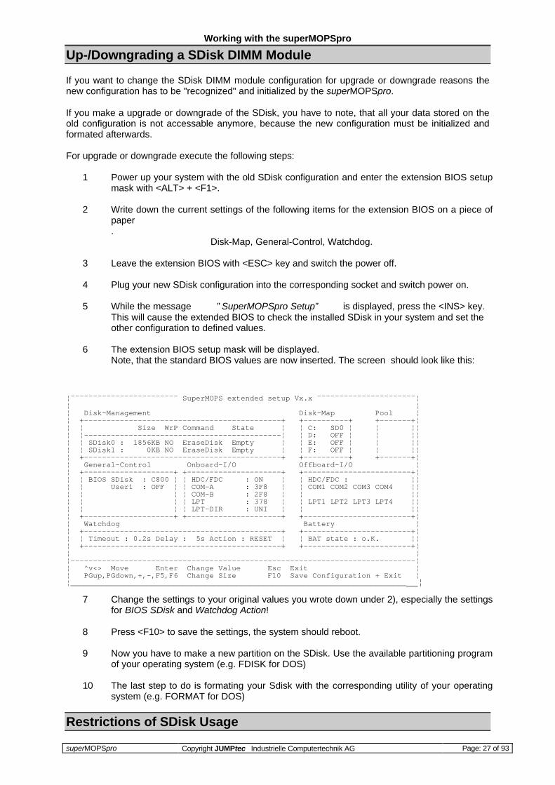
5 While the message ” SuperMOPSpro Setup” is displayed, press the <INS> key.This will cause the extended BIOS to check the installed SDisk in your system and set theother configuration to defined values.
6 The extension BIOS setup mask will be displayed.Note, that the standard BIOS values are now inserted. The screen should look like this:
¦¯¯¯¯¯¯¯¯¯¯¯¯¯¯¯¯¯¯¯¯¯¯¯¯ SuperMOPS extended setup Vx.x ¯¯¯¯¯¯¯¯¯¯¯¯¯¯¯¯¯¯¯¯¯¯¦¦ ¦¦ Disk-Management Disk-Map Pool ¦¦ +--------------------------------------------+ +----------+ +-------+¦¦ ¦ Size WrP Command State ¦ ¦ C: SD0 ¦ ¦ ¦¦¦ ¦--------------------------------------------¦ ¦ D: OFF ¦ ¦ ¦¦¦ ¦ SDisk0 : 1856KB NO EraseDisk Empty ¦ ¦ E: OFF ¦ ¦ ¦¦¦ ¦ SDisk1 : 0KB NO EraseDisk Empty ¦ ¦ F: OFF ¦ ¦ ¦¦¦ +--------------------------------------------+ +----------+ +-------+¦¦ General-Control Onboard-I/O Offboard-I/O ¦¦ +--------------------+ +---------------------+ +------------------------+¦¦ ¦ BIOS SDisk : C800 ¦ ¦ HDC/FDC : ON ¦ ¦ HDC/FDC : ¦¦¦ ¦ User1 : OFF ¦ ¦ COM-A : 3F8 ¦ ¦ COM1 COM2 COM3 COM4 ¦¦¦ ¦ ¦ ¦ COM-B : 2F8 ¦ ¦ ¦¦¦ ¦ ¦ ¦ LPT : 378 ¦ ¦ LPT1 LPT2 LPT3 LPT4 ¦¦¦ ¦ ¦ ¦ LPT-DIR : UNI ¦ ¦ ¦¦¦ +--------------------+ +---------------------+ +------------------------+¦¦ Watchdog Battery ¦¦ +--------------------------------------------+ +------------------------+¦¦ ¦ Timeout : 0.2s Delay : 5s Action : RESET ¦ ¦ BAT state : o.K. ¦¦¦ +--------------------------------------------+ +------------------------+¦¦ ¦¦-----------------------------------------------------------------------------¦¦ ^v<> Move Enter Change Value Esc Exit ¦¦ PGup,PGdown,+,-,F5,F6 Change Size F10 Save Configuration + Exit ¦¦_____________________________________________________________________________¦
7 Change the settings to your original values you wrote down under 2), especially the settingsfor BIOS SDisk and Watchdog Action!
8 Press <F10> to save the settings, the system should reboot.
9 Now you have to make a new partition on the SDisk. Use the available partitioning programof your operating system (e.g. FDISK for DOS)
10 The last step to do is formating your Sdisk with the corresponding utility of your operatingsystem (e.g. FORMAT for DOS)
Restrictions of SDisk Usage

Working with the superMOPSpro
superMOPSpro Copyright JUMPtec Industrielle Computertechnik AG Page: 28 of 93
The optional SDisk won’t work under any protected mode operating system, like WINDOWS 3.1,WINDOWS FOR WORKGROUPS 3.11, WINDOWS NT, OS/2 etc. The reason for this restriction isthe onboard PIC-controller placed between keyboard and keyboard controller. One of the PIC´spurposes is controlling the SDisk access. The above mentioned operating systems emulate thekeyboard and therefore suppress most kind of SDisk accesses.
Watchdog User Interface
The watchdog user interface is implemented in the SDisk BIOS and will only be active when the” BIOS SDisk” option in the extended setup is set to a BIOS location. If this Option is set to OFF thewatchdog can not be accessed via the user interface.
The watchdog can either be handled via the extension setup (described above) or by the user’s ownsoftware. There are two functions available for the programmer. One is the initialization the other thetriggering of the internal superMOPSpro watchdog, with both functions handled by the softwareinterrupt 15hex.
Watchdog Control Functions
Watchdog Init Int 15hInput: AX = E000h BX = 0h to 0FFFFh
Timeout in 0,2s steps0 = watchdog off
CX = 0h to 07FFFh DX = 0h or 1hDelay in 0,2s steps Event: 0 for RESET
1 for IOCHK
Watchdog Trigger Int 15hInput: AX = E001h
Programming Example
Start: MOV AX,0E000h set watchdogMOV BX,96h 150 * 0.2s = 30s timeoutMOV CX,32h 50 * 0.2s = 10s delayMOV DX,0h RESET as eventINT 15h
Trigger: MOV AX,0E001h trigger watchdogINT 15h
The part of the programming example marked with ” start” has to be executed once to initialize thewatchdog, while the ” trigger” part has to be run cyclic at least once before timeout is elapsed.

Peripheral Interfaces
superMOPSpro Copyright JUMPtec Industrielle Computertechnik AG Page: 29 of 93
Peripheral Interfaces
DC Power Connector (X3)
Pin Pin function1 GND2 +5V3 keypin4 +12V5 -5V6 -12V7 GND8 +5V
Power PinsThe superMOPSpro is a +5 V only module. Nevertheless the power connector offers thepossibility to supply with the additional voltages +12V, -12V and -5V which may be needed byother boards in the PC/104 system. The power consumption of all available power pins on thesuperMOPSpro is limited to 5A in total (1A per pin, with 2 pins on the power connector, 2 pinson the XT-bus and 1 pin on the AT-bus) and at GND up to 8A. Systems consuming more then2A shouldn’t be served over the power connector only. Systems consuming more then 5Amust provide power supply through an additional connector on another board.
KeypinThe keypin avoids wrong insertion of the 8 pin power connector offered by JUMPTEC.
Keyboard, Reset, Battery, Speaker (X9)
Pin Signalname
Function 5-pin diodekeyboardadapter
6-pin minidinkeyboardadapter (PS2)
1 SPKR speaker output2 GND ground3 POWERGOOD reset input4 /KLOCK keyboard lock5 KDATA keyboard data 2 16 KCLK keyboard clock 1 57 GND ground 4 38 VCC +5V 5 49 VBAT VBAT input (3,6V)10 POWERGOOD reset input
/KLOCK (keyboard lock)input on CPU modulesoutput on any other moduleinput to the keyboard controller input port 1 bit 7 .
POWERGOOD (reset input)input on CPU modulesopen collector output on all other moduleWhen power good goes high, it starts the reset generator on the CPU module to pull theonboard reset line high after a valid reset period. This pin can also be used as a low activehardware reset for modules.
SPKR (speaker output)open collector output on modules which can drive a loudspeaker.input on modules which connect a 8 Ohm loudspeaker to this pin

Peripheral Interfaces
superMOPSpro Copyright JUMPtec Industrielle Computertechnik AG Page: 30 of 93
An 8 Ohm loudspeaker is connected between SPEAKER and GND. Only one loudspeakershould be connected to this pin. Usually only the CPU drives this pin, however other modulescan also use this signal to drive the system loudspeaker.
KDATA (keyboard data)bi-directional I/O pin on CPU modulesKeyboard data signal.
KCLK (keyboard clock)bi-directional I/O pin on CPU modulesKeyboard clock signal.
VBAT (system battery connection)This pin connects a system battery to all modules.The battery voltage has to be higher than 3.0V and lower than 4.0V. Either a 3V or 3.6Vbattery is recommended.Note, that there is no battery needed to hold the CMOS-setup data. Your configurationconcerning hard disks, floppy drives etc. is automatically saved in an onboard FRAM.Nevertheless the battery is necessary to serve the CMOS date and time while powerconsumption is turned off.
1 (Speaker)
2 (GND)
3,10 (PowerGood)
4 (/KLOCK)
5 (KDATA)
6 (KCLK)
7 (GND)
8 (+ 5V)
9 (VBAT)
352
4 1

Peripheral Interfaces
superMOPSpro Copyright JUMPtec Industrielle Computertechnik AG Page: 31 of 93
Parallel Port (X6)
Pin Signal name Function In / Out DSUB251 /STB data valid out 12 /AFD after CR LF out 143 PD0 data bit 0 I/O 24 /ERR error in 155 PD1 data bit 1 I/O 36 /INIT initialization out 167 PD2 data bit 2 I/O 48 /SLIN select in out 179 PD3 data bit 3 I/O 510,12 GND signal ground -- 18 - 2511 PD4 data bit 4 I/O 613 PD5 data bit 5 I/O 714,16 GND signal ground -- 18 - 2515 PD6 data bit 6 I/O 817 PD7 data bit 7 I/O 918,20 GND signal ground -- 18 - 2519 /ACK acknowledge in 1021 BUSY printer busy in 1122,24 GND signal ground -- 18 - 2523 PE no paper in 1225 SLCT selected in 1326 VCC + 5 V -- NC
The centronics printer interface on the superMOPSpro can be programmed by the extended setup.The user can define the base I/O-addresses 378h, 3BCh, 278h or disable the interface. The parallelport is completely compatible with the parallel port implementation used in the IBM PS-II-paralleladapter.
Register-description
offset read write
0h centronics-port centronics-port
1h status-register not used
2h control-register control-register
3h not used not used
Since the parallel port is bidirectional (set by an special bit in the control-register), the centronics-portallows the microprocessor to read the information on the parallel bus. The status register allows themicroprocessor to read the status of the printer in the five most significant bits. The status bits arePrinter Busy (BUSY), Acknowledge (ACK) which is a handshake function, Paper Out (PE), PrinterSelected (SLCT), and Error (ERR). The control register (xxAh) is a read/write register. The control bitsare found in the six least significant bits of this register. They are Interrupt Enable (IRQ ENB), SelectIn (SLIN), Initialize the Printer (INIT), Autofeed the Paper (AFD), Strobe (STB) and Direction (DIR),which informs the printer of the presence of valid data on the parallel bus.
register Bit7 Bit6 Bit5 Bit4 Bit3 Bit2 Bit1 Bit0
centronics-Port PD7 PD6 PD5 PD4 PD3 PD2 PD1 PD0
status-register BUSY ACK PE SLCT ERR 1 1 1
control-register 1 1 DIR IRQENB
SLIN INIT AFD STB
Peripheral Interfaces
superMOPSpro Copyright JUMPtec Industrielle Computertechnik AG Page: 32 of 93
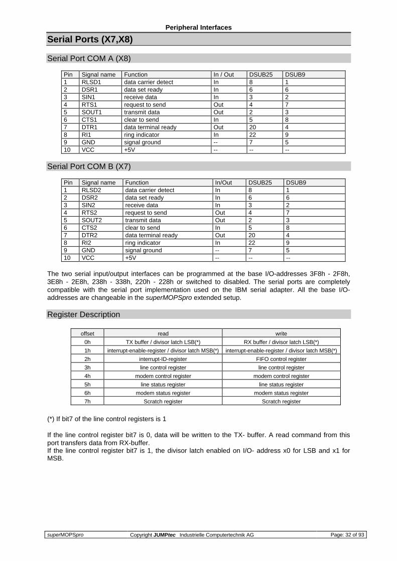
Serial Ports (X7,X8)
Serial Port COM A (X8)
Pin Signal name Function In / Out DSUB25 DSUB91 RLSD1 data carrier detect In 8 12 DSR1 data set ready In 6 63 SIN1 receive data In 3 24 RTS1 request to send Out 4 75 SOUT1 transmit data Out 2 36 CTS1 clear to send In 5 87 DTR1 data terminal ready Out 20 48 RI1 ring indicator In 22 99 GND signal ground -- 7 510 VCC +5V -- -- --
Serial Port COM B (X7)
Pin Signal name Function In/Out DSUB25 DSUB91 RLSD2 data carrier detect In 8 12 DSR2 data set ready In 6 63 SIN2 receive data In 3 24 RTS2 request to send Out 4 75 SOUT2 transmit data Out 2 36 CTS2 clear to send In 5 87 DTR2 data terminal ready Out 20 48 RI2 ring indicator In 22 99 GND signal ground -- 7 510 VCC +5V -- -- --
The two serial input/output interfaces can be programmed at the base I/O-addresses 3F8h - 2F8h,3E8h - 2E8h, 238h - 338h, 220h - 228h or switched to disabled. The serial ports are completelycompatible with the serial port implementation used on the IBM serial adapter. All the base I/O-addresses are changeable in the superMOPSpro extended setup.
Register Description
offset read write
0h TX buffer / divisor latch LSB(*) RX buffer / divisor latch LSB(*)
1h interrupt-enable-register / divisor latch MSB(*) interrupt-enable-register / divisor latch MSB(*)
2h interrupt-ID-register FIFO control register
3h line control register line control register
4h modem control register modem control register
5h line status register line status register
6h modem status register modem status register
7h Scratch register Scratch register
(*) If bit7 of the line control registers is 1
If the line control register bit7 is 0, data will be written to the TX- buffer. A read command from thisport transfers data from RX-buffer.If the line control register bit7 is 1, the divisor latch enabled on I/O- address x0 for LSB and x1 forMSB.
Peripheral Interfaces
superMOPSpro Copyright JUMPtec Industrielle Computertechnik AG Page: 33 of 93
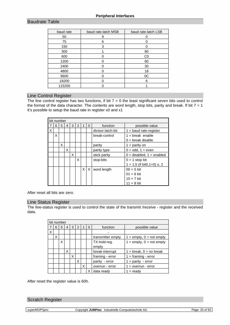
Baudrate Table
baud rate baud rate-latch MSB baud rate-latch LSB50 9 075 6 0150 3 0300 1 80600 0 C0
1200 0 602400 0 304800 0 189600 0 0C19200 0 6
115200 0 1
Line Control RegisterThe line control register has two functions, if bit 7 = 0 the least significant seven bits used to controlthe format of the data character. The contents are word length, stop bits, parity and break. If bit 7 = 1it’s possible to setup the baud rate in register x0 and x1
bit number7 6 5 4 3 2 1 0 function possible valueX divisor-latch-bit 1 = baud rate-register
X break-control 1 = break enable0 = break disable
X parity 1 = parity onX parity type 0 = odd, 1 = even
X stick parity 0 = disabled, 1 = enabledX stop-bits 0 = 1 stop bit
1 = 1,5 (if bit0,1=0) o. 2X X word length 00 = 5 bit
01 = 6 bit10 = 7 bit11 = 8 bit
After reset all bits are zero.
Line Status RegisterThe line-status register is used to control the state of the transmit /receive - register and the receiveddata.
bit number7 6 5 4 3 2 1 0 function possible valueX -
X transmitter empty 1 = empty, 0 = not emptyX TX-hold-reg.
empty1 = empty, 0 = not empty
X break-interrupt 1 = break, 0 = no breakX framing - error 1 = framing - error
X parity - error 1 = parity - errorX overrun - error 1 = overrun - error
X data ready 1 = ready
After reset the register value is 60h.
Scratch Register

Peripheral Interfaces
superMOPSpro Copyright JUMPtec Industrielle Computertechnik AG Page: 34 of 93
The Scratch register is an 8-bit read/write register that has no effect on any channel in the I/Ocontroller. It is intended as a scratchpad register used by the programmer to hold data temporarily.
Modem Control RegisterThe modem control register is used to control the interface with the modem or data set.
bit number7 6 5 4 3 2 1 0 function possible valueX X X -
X loop-testmode 0 = loop off, 1 = loop onX interrupt enable 0 = disabled, 1 = enabled
X -X RTS-output 0 = low, 1 = high
X DTR-output 0 = low, 1 = high
After reset all bits are zero.
Modem Status RegisterThe modem-status register is used to control the state and the change of the modem input lines.
bit number7 6 5 4 3 2 1 0 function possible valueX RLSD complement 0/1
X RI complement 0/1X DSR complement 0/1
X CTS complement 0/1X delta RLSD 1 = changed
X TERI 1 = RI changed to offX delta DSR 1 = changed
X delta CTS 1 = changed
After reset the four least significant bits are 0, the most significant bits have the state of theircorrespondended pin.
Interrupt ID RegisterThe interrupt-ID-register is used to identify communication interrupts.
bit number7 6 5 4 3 2 1 0 function possible valueX X X X X -
X X interrupt-ID 1 = modem-status1 = TX hold registerempty1 = receive data ready1 = RX-line status
X interrupt pending 1 = interrupt pending0 = no interrupt pending
After reset the value of the register is 01h.

Peripheral Interfaces
superMOPSpro Copyright JUMPtec Industrielle Computertechnik AG Page: 35 of 93
Interrupt Enable RegisterThe interrupt-enable-registers are used to enable independently the four serial channel interruptswhich activates the interrupt output. To enable the interrupt output, bit3 of the modem-control-registermust be set. If bit7 of the line-control-register is set, the MSB of the baud rate-register is enabledinstead of the interrupt-enable-register .
bit number7 6 5 4 3 2 1 0 function possible valueX X X X -
X modem status 1 = interrupt enabledX receiver-line status 1 = interrupt enabled
X TX-hold-reg.empty
1 = interrupt enabled
X data ready 1 = interrupt enabled
After reset all bits are zero.
FIFO Control RegisterThe FIFO control register is a write only register at the same location as the interrupt ID register. Thisregister is used to enable and clear the FIFOs, set the receiver FIFO trigger level.
bit number7 6 5 4 3 2 1 0 function possible valueX X trigger level of the
receiver FIFO00 = 1 byte01 = 4 bytes10 = 8 bytes11 = 14 bytes
X X X - -X clear transmit
FIFO1 = clear
X clear receive FIFO 1 = clearX enable disable
FIFOs1 = eanable FIFOs0 = disable FIFOs
If bit 0 = 0 clears all bytes in the transmit and receive FIFO, it must be 1 to write to other bits in thisregister. Bits 1 and 2 are self-clearing.
Floppy Connector (X4)
Pin Signal Function Pin Signal Function1 VCC + 5V 2 IDX index3 VCC + 5V 4 DS0 drive select 05 VCC + 5V 6 /DCHNG disk change7 NC - 8 NC -9 NC - 10 Mo0 motor on11 NC - 12 DIR direction select13 NC - 14 STEP step15 GND ground 16 WD write data17 GND ground 18 WG write gate19 GND ground 20 TR00 track 0021 GND ground 22 WP write protect23 GND ground 24 RD read data25 GND ground 26 SIDE side one select
IDE Connector for 2,5" Hard Disk (X10)

Peripheral Interfaces
superMOPSpro Copyright JUMPtec Industrielle Computertechnik AG Page: 36 of 93
Pin Signal Function Pin Signal Function1 /RESET reset 2 GND ground3 D7 data 7 4 D8 data 85 D6 data 6 6 D9 data 97 D5 data 5 8 D10 data 109 D4 data 4 10 D11 data 1111 D3 data 3 12 D12 data 1213 D2 data 2 14 D13 data 1315 D1 data 1 16 D14 data 1417 D0 data 0 18 D15 data 1519 GND ground 20 NC keypin21 NC 22 GND ground23 /IOW I/O write 24 GND ground25 /IOR I/O read 26 GND ground27 NC 28 BALE reserved29 NC 30 GND ground31 IRQ14 interrupt 14 32 /IOCS16 I/O CS 1633 SA1 address 1 34 NC35 SA 0 address 0 36 SA2 address 237 /CS0 IDE CS 0 38 /CS1 IDE CS 139 /HDLED active 40 GND ground41 VCC +5V (Logic) 42 VCC +5V (Motor)43 GND ground 44 NC
Feature Connector (X5)
Pin Signals Function Pin Signals Function1 ISPDEV reserved 2 RAMWI reserved3 /HDLED HD active 4 VCC + 5V5 MDATA PS2 mouse data 6 VCC + 5V7 MCLK PS2 mouse clock 8 GND ground9 /RLSDB RS485 DCD 10 /DSRB RS485 DSR11 SINB RS485 RXD 12 /RTSB RS485 RTS13 SOUTB RS485 TXD 14 /CTSB RS485 CTS15 /DTRB RS485 DTR 16 /RIB RS485 RI17 GND ground 18 LKLED Link LED19 /EN enable RS485 20 VCC + 5V21 I2DAT I2C bus data 22 VCC + 5V23 I2CLK I2C bus clock 24 GND ground25 PowerGood reset 26 LNLED Line LED
ISPDEV, RAMWISignals, which are used during manufacturing do not use !
/HDLEDSignal, which indicates access to HDD

Peripheral Interfaces
superMOPSpro Copyright JUMPtec Industrielle Computertechnik AG Page: 37 of 93
MDATA, MCLKSignals for connecting PS2-Mouse.Note, that PS2-Mouse support is not enabled by the BIOS.
/RLSDB, /DSRB, SINB, /RTSB, SOUTB, /CTSB, /CTRB, /RIBThese signals based on TTL-Level and corresponds with the V24-level signals of serial port 2.They are used to provide IRDA or RS485 support.Attention: It is necessary to disable the V24-driver of serial port 2 if anyof that signals are used.
/ENA low-level on Signal /EN disables the V24-driver of serial port 2.
POWERGOODWhen POWERGOOD goes high, it starts the reset generator on a CPU module to pull theonboard reset high after a valid reset period. This pin can also be used as a low activehardware reset for modules.
I2DAT, I2CLKoutput on I2C-bus devicessee I2C-bus chapter for more detailed information
LNLEDActive-low output indicating transmission or reception of frames or detection of a collision.May be connected to external LED.
LKLEDActive-low output indicating valid 10BASE-T link pulses. May be connected to external LED.
Ethernet Connector (X11)
Pin Signalname Function In/Out1 TXD+ 10BASE-T Transmit differential Output2 TXD- 10BASE-T Transmit differential Output3 RXD+ 10BASE-T Receive differential Input4 NC unused Pin5 NC unused Pin6 RXD- 10BASE-T Receive differential Input7 NC unused Pin8 NC unused Pin
TXD+, TXD-Differential output pair drives 10 Mb/s Manchester-encoded data to the 10BASE-T transmitlines.
RXD+, RXD-Differential input pair receives 10 MB/s Manchester encoded data from the 10BASE-Treceive lines.
RS485 Option
The TTL-Signals of COM 2 are available on the feature connector X5. Therefore it is optionallypossible to connect an RS485 Converter to X5. Before these signals can be used, the COM2 V24drivers must be disabled by pulling the /EN signal low.
Peripheral Interfaces
superMOPSpro Copyright JUMPtec Industrielle Computertechnik AG Page: 38 of 93
IRDA interface
Alternatively an IRDA-transceiver can be connected to the TTL signals of COM2 at connector X5 toallow for bidirectional wireless data transfer at speeds up to 115 kbaud. (No BIOS- or software supportis provided for this feature.).
NOTE: IRDA (named after the standardizing group ” InfraRed Data Association” ) defines a standardfor High Speed infrared data transfer (over distances of about 1 metre). It is supported by manysuppliers at chip, module or device level.
I2C-Bus
Introduction to I2C-Bus
The inter-IC bus (I2C) is a two-wired serial bus and provides a sort of small area network between thecircuits of one system and between different systems. Any device with build-in I2C bus interface canbe connected to the system by simply clipping it to the I2C bus. It consists of two bidirectional lines forserial data (I2DAT) and serial clock (I2CLK). Every device connected can be master or slave, sothere is no central master. A device addressed as a slave during one data transfer could possibly bethe master for the next data transfer. Devices are also free to transmit or receive data during atransfer. The inherent synchronization process in connection with the wired AND technique allows fastdevices to communicate with slower ones.
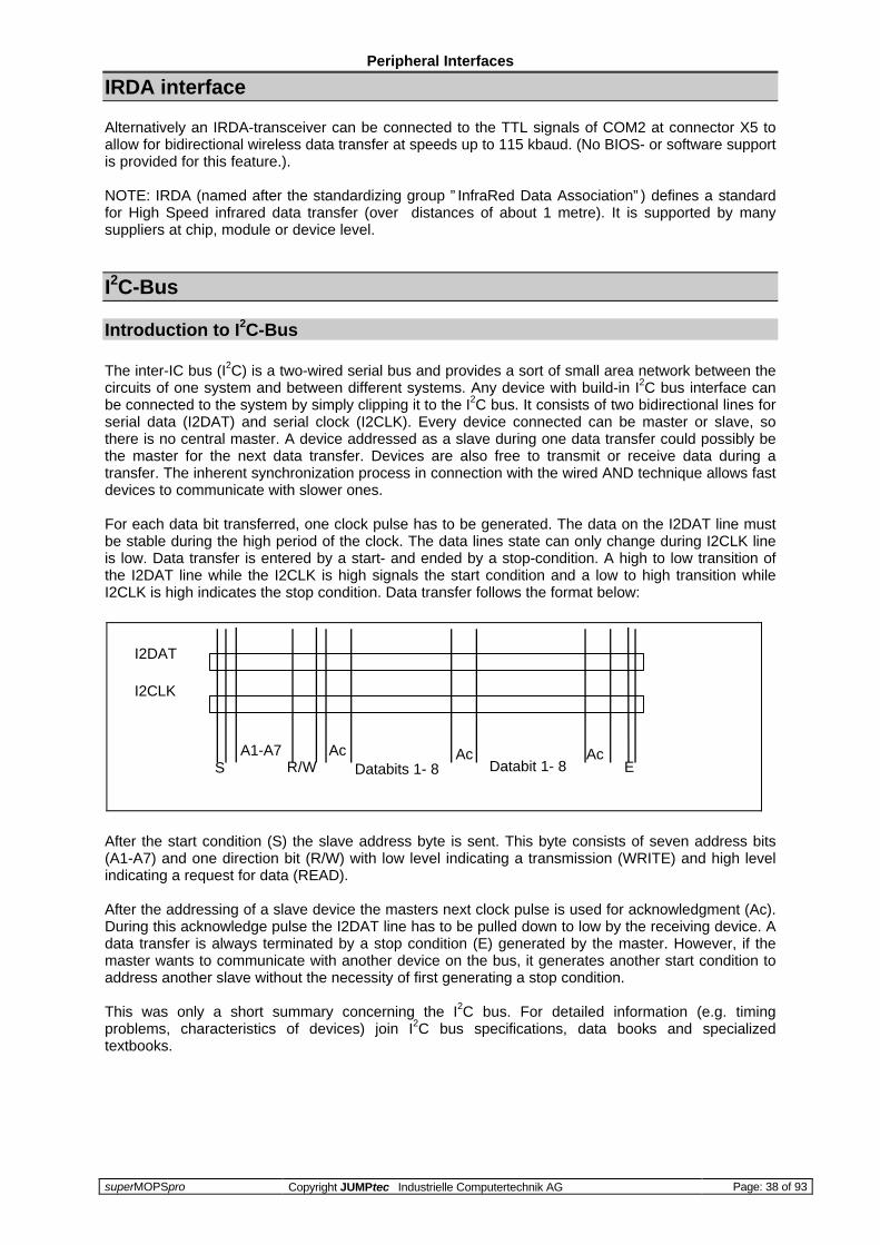
For each data bit transferred, one clock pulse has to be generated. The data on the I2DAT line mustbe stable during the high period of the clock. The data lines state can only change during I2CLK lineis low. Data transfer is entered by a start- and ended by a stop-condition. A high to low transition ofthe I2DAT line while the I2CLK is high signals the start condition and a low to high transition whileI2CLK is high indicates the stop condition. Data transfer follows the format below:
After the start condition (S) the slave address byte is sent. This byte consists of seven address bits(A1-A7) and one direction bit (R/W) with low level indicating a transmission (WRITE) and high levelindicating a request for data (READ).
After the addressing of a slave device the masters next clock pulse is used for acknowledgment (Ac).During this acknowledge pulse the I2DAT line has to be pulled down to low by the receiving device. Adata transfer is always terminated by a stop condition (E) generated by the master. However, if themaster wants to communicate with another device on the bus, it generates another start condition toaddress another slave without the necessity of first generating a stop condition.
This was only a short summary concerning the I2C bus. For detailed information (e.g. timingproblems, characteristics of devices) join I2C bus specifications, data books and specializedtextbooks.
SA1-A7
R/WAc
Databits 1- 8Ac
Databit 1- 8Ac
E
I2DAT
I2CLK

Peripheral Interfaces
superMOPSpro Copyright JUMPtec Industrielle Computertechnik AG Page: 39 of 93
I2C Bus on JUMPtec Boards
The I2C bus interface on JUMPtec boards has to be realized by the customer via software whichdrives the two lines I2DAT and I2CLK following the I2C bus specifications. The basic hardware todesign the software interface is standard on this device. This kind of interface does not supportexternal masters.
On different kinds of JUMPtec boards the two I2C bus lines are not offered on identical connectors.Join your manual, if you’re not sure using the right connector or pins for your I2C application.
The following drawing show the bus interface and the onboard devices connected to the I2C bus onthe JUMPtec boards.
I2C Bus on superMOPS/486DX-1 and superMOPS/586DX-1
I/O address to generate /CS : 50h
Device address of EEPROM : 1010000Device address of PIC16C84 : 1011000
Attention: These devices are for BIOS-access only, reading from or writing tothem may cause data corruption and system failure.
Example: Guess you’re writing a software utility and want the I2DATline to be pulled HIGH. You have to use I/O-port 50h and setthe data lines D0 to D3, with D3=1 holding the output level for I2DATand D2 to D0=110 choosing the right output line Q6.
The corresponding OUT instruction would be : OUT 50h,0Eh
Several OUTs and INs will be necessary to address one I2C bus device and write or read a byte,because the start and stop conditions and every single bit have to be set separately as well as theI2CLK line.
SD0
VCC
S0S1S2
D
GQ7
Q6
/CSorIOW
D0
D1
D2
D3
/CS or IOR
21
23
VCC
GND8
6
X5

The JIDA (JUMPtec Intelligent Device Architecture) Standard
superMOPSpro Copyright JUMPtec Industrielle Computertechnik AG Page: 40 of 93
The JIDA (JUMPtec Intelligent Device Architecture)Standard
Every board with onboard BIOS extension shall support the following function calls, which supplyinformation about the board. JIDA functions are called via Interrupt 15h with AH=EAh, AL=functionnumber, DX=4648h (security word), CL=board number (starting with 1).
The interrupt will return with CL#0, if a board with the number specified in CL does not exist. CL willbe equal to 0 if the board number exists. In this case, the content of DX is used to determine, ifoperation was successful. DX=6B6Fh indicates successful operation, any other value indicates anerror.
To get information about the installed boards following the JIDA standard, the following procedrue isrecommended:
Call ” Get Device ID” with CL=1. The name of the first device installed will be returned. If result was” Board exists” (CL=0), increment CL and call ” Get Device ID” again. Repeat until result is ” Boardnot present” (CL#0). You now know the names of all boards within your systen that follow the JIDAstandard. More information about a specific board may then be obtained by calling the appropriateinquiry function with the board’s number in CL.
WARNING: Association between board and board number may change due to configuration changes.Do not rely on any association between board and board number. Instead, alway use the proceduredescribed in the preceding paragraph first, to determine the association between board and boardnumber.
The source of a Turbo-Pascal unit called JIDA_ACC.PAS showing JIDA access is included on theSupport Disk.

The JIDA (JUMPtec Intelligent Device Architecture) Standard
superMOPSpro Copyright JUMPtec Industrielle Computertechnik AG Page: 41 of 93
et Manufacturer ID Int 15hInput: AX = EA00h DX = 4648h
CL = Board number (1=first board a.s.o.)ES:BX = Pointer to destination data area
Output: CL=0: Board presentCL≠0: Board not present
DX=6B6Fh: Function successfulDX≠6B6Fh: Error
Description: If CL=0 and DX=6B6Fh, then 4 Byte manufacturer ID were copied to thearea pointed to by ES:BXBy default, the result will be ” JUMP” .Note: There is no ending zero byte.Function must be implemented on every device supporting the JIDA.
Get Device ID Int 15hInput: AX = EA01h DX = 4648h
CL = Board numberES:BX = Pointer to destination data area
Output: CL=0: Board presentCL≠0: Board not present
DX=6B6Fh: Function successfulDX≠6B6Fh: Error
Description: If CL=0 and DX=6B6Fh, then 7 Byte device ID were copied to area pointedto by ES:BXBy default, the result will be ” SMOPSP ” .Note: There is no ending zero byte.Function must be implemented on every device supporting the JIDA.
Get Manufacturing Date Int 15hInput: AX = EA02h DX = 4648h
CL = Board number
Output: CL=0: Board presentCL≠0: Board not present
DX=6B6Fh: Function successfulDX≠6B6Fh: Fn.not implemented
BX = Manufacturing date
Description If CL=0 and DX=6B6Fh, then BX=Manufacturing date. Date format is thesame as used for DOS files:Bit0..4: DayBit5..8: MonthBit9..15: Years since 1980
Get Serial Number Int 15hInput: AX = EA03h DX = 4648h
CL = Board numberES:BX = Pointer to destination data area
Output: CL=0: Board presentCL≠0: Board not present
DX=6B6Fh: Function successfulDX≠6B6Fh: Fn.not implemented
Description: If CL=0 and DX=6B6Fh, then 10 Byte serial number were copied to areapointed to by ES:BXThe result is different for each single superMOPSpro.Note: There is no ending zero byte.
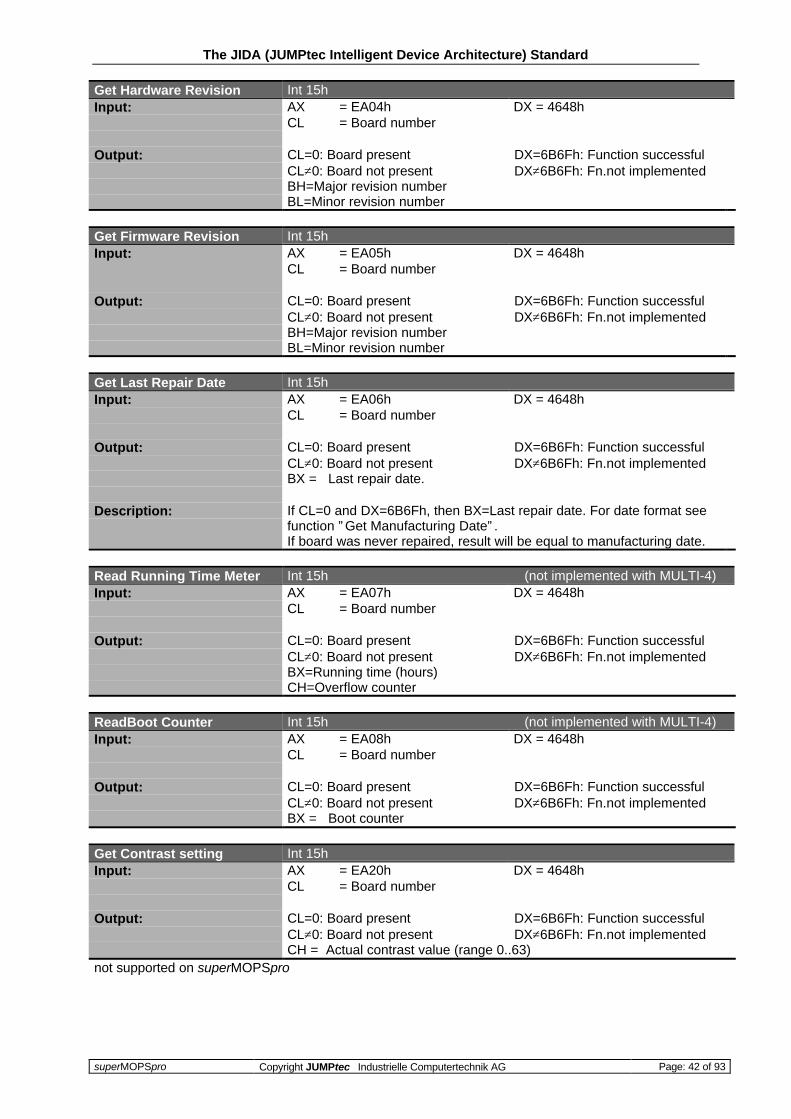
The JIDA (JUMPtec Intelligent Device Architecture) Standard
superMOPSpro Copyright JUMPtec Industrielle Computertechnik AG Page: 42 of 93
Get Hardware Revision Int 15hInput: AX = EA04h DX = 4648h
CL = Board number
Output: CL=0: Board presentCL≠0: Board not present
DX=6B6Fh: Function successfulDX≠6B6Fh: Fn.not implemented
BH=Major revision numberBL=Minor revision number
Get Firmware Revision Int 15hInput: AX = EA05h DX = 4648h
CL = Board number
Output: CL=0: Board presentCL≠0: Board not present
DX=6B6Fh: Function successfulDX≠6B6Fh: Fn.not implemented
BH=Major revision numberBL=Minor revision number
Get Last Repair Date Int 15hInput: AX = EA06h DX = 4648h
CL = Board number
Output: CL=0: Board presentCL≠0: Board not present
DX=6B6Fh: Function successfulDX≠6B6Fh: Fn.not implemented
BX = Last repair date.
Description: If CL=0 and DX=6B6Fh, then BX=Last repair date. For date format seefunction ” Get Manufacturing Date” .If board was never repaired, result will be equal to manufacturing date.
Read Running Time Meter Int 15h (not implemented with MULTI-4)Input: AX = EA07h DX = 4648h
CL = Board number
Output: CL=0: Board presentCL≠0: Board not present
DX=6B6Fh: Function successfulDX≠6B6Fh: Fn.not implemented
BX=Running time (hours)CH=Overflow counter
ReadBoot Counter Int 15h (not implemented with MULTI-4)Input: AX = EA08h DX = 4648h
CL = Board number
Output: CL=0: Board presentCL≠0: Board not present
DX=6B6Fh: Function successfulDX≠6B6Fh: Fn.not implemented
BX = Boot counter
Get Contrast setting Int 15hInput: AX = EA20h DX = 4648h
CL = Board number
Output: CL=0: Board presentCL≠0: Board not present
DX=6B6Fh: Function successfulDX≠6B6Fh: Fn.not implemented
CH = Actual contrast value (range 0..63)not supported on superMOPSpro

The JIDA (JUMPtec Intelligent Device Architecture) Standard
superMOPSpro Copyright JUMPtec Industrielle Computertechnik AG Page: 43 of 93
Set Contrast Int 15hInput: AX = EA21h DX = 4648h
CL = Board numberCH = New contrast value
Output: CL=0: Board presentCL≠0: Board not present
DX=6B6Fh: Function successfulDX≠6B6Fh: Fn.not implemented
Description: Valid range for contrast is 0..63. Other values will be ignored.not supported on superMOPSpro
Disable DC/DC Converter Int 15hInput: AX = EA22h DX = 4648h
CL = Board number
Output: CL=0: Board presentCL≠0: Board not present
DX=6B6Fh: Function successfulDX≠6B6Fh: Fn.not implemented
not supported on superMOPSpro
Enable DC/DC Converter Int 15hInput: AX = EA23h DX = 4648h
CL = Board number
Output: CL=0: Board presentCL≠0: Board not present
DX=6B6Fh: Function successfulDX≠6B6Fh: Fn.not implemented
not supported on superMOPSpro
Get Matrix Translation Table Int 15hInput: AX = EA30h DX = 4648h
CL = Board numberES:BX = Pointer to destination data area
Output: CL=0: Board presentCL≠0: Board not present
DX=6B6Fh: Function successfulDX≠6B6Fh: Fn.not implemented
Description: 72 Byte matrix keyboard translation table will be copied to area pointedto by ES:BX
not supported on superMOPSpro
Set Matrix Translation Table Int 15hInput: AX = EA31h DX = 4648h
CL = Board numberES:BX = Pointer to new translation table
Output: CL=0: Board presentCL≠0: Board not present
DX=6B6Fh: Function successfulDX≠6B6Fh: Fn.not implemented
Description: New matrix keyboard translation table will be copied from area pointed toby ES:BX
not supported on superMOPSpro

The JIDA (JUMPtec Intelligent Device Architecture) Standard
superMOPSpro Copyright JUMPtec Industrielle Computertechnik AG Page: 44 of 93
Get Matrix Translation Entry Int 15hInput: AX = EA32h DX = 4648h
CL = Board numberBH = Matrix line (0..7 allowed)BL = Matrix row (0..8 allowed)
Output: CL=0: Board presentCL≠0: Board not present
DX=6B6Fh: Function successfulDX≠6B6Fh: Fn.not implemented
CH = Table entry (undefined if BH or BL are invalid)not supported on superMOPSpro
Set Matrix Translation Entry Int 15hInput: AX = EA33h DX = 4648h
CL = Board numberBH = Matrix line (0..7 allowed)BL = Matrix row (0..8 allowed)CH = New Entry
Output: CL=0: Board presentCL≠0: Board not present
DX=6B6Fh: Function successfulDX≠6B6Fh: Fn.not implemented
not supported on superMOPSpro
Read User Byte fromEEPROM
Int 15h
Input: AX = EA40h DX = 4648hCL = Board numberBH = Number of byte to read (0..15 allowed)
Output: CL=0: Board presentCL≠0: Board not present
DX=6B6Fh: Function successfulDX≠6B6Fh: Fn.not implemented
BL = Value read
Write User Byte to EEPROM Int 15hInput: AX = EA41h DX = 4648h
CL = Board numberBH = Number of byte to write (0..15 allowed)BL = Value to write
Output: CL=0: Board presentCL≠0: Board not present
DX=6B6Fh: Function successfulDX≠6B6Fh: Fn.not implemented

The JIDA (JUMPtec Intelligent Device Architecture) Standard
superMOPSpro Copyright JUMPtec Industrielle Computertechnik AG Page: 45 of 93
Read OC Output State Int 15hInput: AX = EA50h DX = 4648h
CL = Board number
Output: CL=0: Board presentCL≠0: Board not present
DX=6B6Fh: Function successfulDX≠6B6Fh: Fn.not implemented
CH = Actual output state
Description: Data format: CH = xxxxxxba, where b = OC1, a = OC0
Switch OC Outputs Int 15hInput: AX = EA51h DX = 4648h
CL = Board numberCH = New output state
Output: CL=0: Board presentCL≠0: Board not present
DX=6B6Fh: Function successfulDX≠6B6Fh: Fn.not implemented
Description: Data format: CH = xxxxxxba, where b = OC1, a = OC0
Network Operation
superMOPSpro Copyright JUMPtec Industrielle Computertechnik AG Page: 46 of 93
Network Operation
Overview
The Crystal LAN(tm) CS8900 ISA Ethernet Adapter from Crystal Semiconductor follows IEEE 802.3standards and support half- or full-duplex operation in ISA bus computers on 10 Mbps Ethernetnetworks. The adapter is designed for operation in 16-bit ISA or EISA bus expansion slots and isavailable in 10BaseT-only or 3-media configurations (10BaseT, 10Base2, and AUI for 10Base-5 orfibre networks).
SYSTEM REQUIREMENTS
The following hardware is required:
• Crystal LAN(tm) CS8900 ISA Ethernet Adapter• IBM or IBM-compatible PC with:• An 80386 or higher processor• 16 bytes of contiguous I/O space between 210h - 370h• One available IRQ (5,10,11,or 12 for the CS8900)• Appropriate cable with 8-positions RJ45 connector (connector for AUI, 10BASE-2) for your
network topology. The following software is required:
• CS8900 Setup and Device Driver Software diskette.
• Installation diskettes or CD-ROM for your client and/or network operating system.

Network Operation
superMOPSpro Copyright JUMPtec Industrielle Computertechnik AG Page: 47 of 93
FILES ON THE SETUP AND DEVICE DRIVER DISK \ ¦ ¦ SETUP.EXE ................ CS89XX Setup and Diagnostic Utility ¦ README.EXE ............... This application ¦ DISK1 .................... Installation file ¦ OEMSETUP.INF ............. Driver installation file for WFWG ¦ OEMSETNT.INF ............. Driver installation file for Win NT ¦ NETCSC.INF ............... Driver installation file for WIN 95 ¦ ENDS3ISA.VXD ............. NDIS 3.0 driver (Windows 95) ¦ ENDS3ISA.SYS ............. NDIS 3.0 driver (Windows NT) ¦ ENDS3ISA.386 ............. NDIS 3.0 driver (Win for Workgroups) ¦ !CS89XX.CFG .............. EISA configuration file ¦ +--DMI ¦ CS89DMI.MIF ............ CS89XX MIF file ¦ CS89DMI.DLL ............ DMI Component Interface for OS/2 ¦ CS89DMI.OVL ............ DMI Component Interface for DOS ¦ +--BOOTPROM ¦ RBOOT.ROM ............. BootPROM image for RIPL ¦ +--MSLANMAN.DOS ¦ +-DRIVERS ¦ +-ETHERNET ¦ ¦ +-ENDS2ISA ¦ ¦ ENDS2ISA.DOS .. NDIS 2.0.1 DOS driver ¦ ¦ PROTOCOL.INI .. Sample PROTOCOL.INI file ¦ ¦ ¦ +-NIF ¦ ENDS2ISA.NIF .... Used by LAN Manager setup utility ¦ +--MSLANMAN.OS2 ¦ +-DRIVERS ¦ +-ETHERNET ¦ ¦ +-ENDS2ISA ¦ ¦ ENDS2ISA.OS2 .. NDIS 2.0.1 OS/2 driver ¦ ¦ PROTOCOL.INI .. Sample PROTOCOL.INI file ¦ ¦ ¦ +-NIF ¦ ENDS2ISA.NIF .... Used by LAN Manager setup utility ¦ +--NETWARE ¦ EODIISA.COM ........... Netware 3.12, 4.X server driver ¦ EODIISA.LDI ........... Server driver installation file ¦ +--DOS ¦ ENDS2ISA.DOS .......... NDIS 2.0.1 DOS driver ¦ ENDS2ISA.NIF .......... NDIS 2.0.1 installation file ¦ PROTOCOL.INI .......... NDIS 2.0.1 configuration file ¦ EODIISA.COM ........... NetWare ODI DOS client driver ¦ EODIISA.INS ........... NetWare DOS client installation file ¦ NET.CFG ............... NetWare DOS client configuration file ¦ +--OS/2 ¦ ENDS2ISA.OS2 .......... NDIS 2.0.1 OS/2 driver ¦ ENDS2ISA.NIF .......... NDIS 2.0.1 installation file ¦ PROTOCOL.INI .......... NDIS 2.0.1 configuration file ¦ EODIISA.SYS ........... NetWare OS/2 ODI client driver ¦ NDS.MSG ............... LANTRAN message file ¦ NET.CFG ............... NetWare OS/2 client configuration file ¦ +--PCKTDRVR EPKTISA.COM ........... Packet driver for DOS workstations SOURCE.ZIP ............ Source files for packet driver

Network Operation
superMOPSpro Copyright JUMPtec Industrielle Computertechnik AG Page: 48 of 93
DESKTOP MANAGEMENT INTERFACE (DMI) INTERFACE DMTF Desktop Management Interface (DMI) support for the CS8900 adapter is provided through theODI client (DOS and OS/2) and NDIS 2.0.1 (DOS and OS/2) device drivers. The three files requiredto implement this interface are provided in the \DMI directory of the "CS8900 Setup and DeviceDriver Software" diskette: • CS89DMI.MIF -- Management Information Format (MIF) file describing the charctersitics of the
CS8900 based adapters.
• CS89DMI.DLL -- Component Interface for the OS/2 operating system (supports both the OS/2ODI and NDIS 2.0.1 device drivers).
• CS89DMI.OVL -- Component Interface for the DOS operating system (supports both the DOSODI and NDIS 2.0.1 device drivers).
Installation procedures are specific to a particular management application. Refer to yourmanagement application's documentation for the installation of the required DMI support files.
Installation
INSTALLATION OVERVIEW
Perform the following steps to install and configure you CS8900 ISA Ethernet Adapter:
1. Install the adapter in an available ISA or EISA slot. (On JUMPtec products the controller ismounted directly on board, therefore this step is not necessary.)
2. Connect your network cable. 3. Configure the adapter. Configuration is not required if installing a CS8900-based adapter and the
default configuration is acceptable. 4. Install the device driver and support files. 5. Perform diagnostic tests if needed.
ADAPTER INSTALLATION
• Turn off the computer and remove its cover if necessary • Connect your network cable. The cable must be connected before loading the driver. If your
adapter supports multiple cable types (twisted-pair, thin coax, and AUI connection), connect onlyone type of cable to the adapter at a time.
• Continue with the section on Adapter Configuration.

Network Operation
superMOPSpro Copyright JUMPtec Industrielle Computertechnik AG Page: 49 of 93
CS8900-BASED ADAPTER CONFIGURATION
CS8900-based adapters shipped from Crystal Semiconductor are configured with the following"default" settings:
Operation Mode: Memory ModeIRQ: 10Base I/O Address: 300Memory Base Address: D0000Optimization: DOS ClientTransmission Mode: Half-duplexBootProm: NoneMedia Type: Autodetect (3-media cards) or 10BASE-T (10BASE-T only adapter)
You should only change the default configuration settings if conflicts with another adapter exist. (Seethe section on resolving I/O-conflicts in Testing and Troubleshooting.) To change the adapter'sconfiguration run the CS8900 SetupUtility after the adapter is installed.
WINDOWS FOR WORKGROUPS - NDIS 3.0 DRIVER INSTALLATION
Use the NDIS 3.0 driver (ENDS3ISA.386) in a Windows for Workgroups Network environment or toconnect a Windows for Workgroups client to a Windows NT server.
1) Start Windows. From the Program Manager double click on the "Network" group Icon. 2) Double click on the "Network Setup" icon to start the Network Setup utility. 3) Click on the "Networks" button. 4) Select the "Install Microsoft Windows Network" option and click on the "OK" button. 5) Select the "Drivers..." button at the bottom of the dialog box. 6) From the "Network Drivers" panel select "Add Adapter". 7) Select the "Unlisted or Updated Network Adapter" from the Network Adapters list and click "OK". 8) When prompted, insert the "CS8900 Setup and Device Driver Software" diskette in drive A: and
click "OK" to accept the default path (A:\). 9) The next dialog box lists adapter drivers. Select "Crystal (CS8900)" and click "OK". 10) You will be returned to the "Network Drivers" window. Click the "Close" button. 11) On the "Network Setup" panel, click "OK'". 12) Respond "Yes" to any update messages. Insert the Windows for Workgroups system disk(s) as
prompted. 13) When the installation process is complete, exit and restart Windows for Workgroups for the
changes to take effect.

Network Operation
superMOPSpro Copyright JUMPtec Industrielle Computertechnik AG Page: 50 of 93
WINDOWS FOR WORKGROUPS - DOS ODI CLIENT DRIVER INSTALLATION
Use the DOS ODI driver (EODIISA.COM) to connect a Windows for Workgroups client to a NovellNetWare 3.12 or 4.X server. Perform the installation using Novell's ” NetWare Client forDOS/WINDOWS” Installation package.
1) From a DOS prompt start the Novell installation program from the NetWare WSDOS_1 diskette(NetWare Client for DOS/WIN, Disk 1).
2) At the NetWare Client Installation panel set the destination directory to where you want to store
your NetWare files. The directory will be created if it does not exist. 3) Make sure you have answered "Yes" to the question about modifying your AUTOEXEC.BAT and
CONFIG.SYS files. If you wish to use Windows as a NetWare client answer "Yes" to installsupport for Windows and specify the path to your Windows directory.
4) Highlight the option to select the driver and press <ENTER>. 5) From the "Network Board" dialog page to the end of the list and select the "Other Drivers" option. 6) Insert the drivers diskette. Press <ENTER> to accept the default path. 7) Choose "Crystal ISA Ethernet Adapter EODIISA" as the driver. 8) When the "Settings" panel is displayed enter selections for the desired Frame Type(s). Valid
frame types are:
Ethernet_802.2 (default) Ethernet_802.3 Ethernet_II Ethernet_SNAP
Up to a maximum of four frame types are supported.
NOTE: The first frame type you specify must be one used by the IPX protocol on the NetWareserver to which you wish to connect. Ethernet_802.2 is the default frame type for NetWare 3.12and 4.X servers. (Contact your Network Administrator to determine the frame types supported byyour server.)
An optional Node Address can be assigned if desired. Only assign a local Node Address inaccordance with IEEE 802.2 specifications. A universally administered address is assigned at thefactory and is used by default.
9) Return to the NetWare Client Install panel, select the "Highlight here and press <Enter> to install"option and press <ENTER>.
10) Exchange disks as prompted. 11) When the installation process is complete, reboot the system. 12) The installation process will automatically configure Windows for Workgroups as a NetWare
client. Be sure to login to the file server from the DOS prompt each time before you startWindows.

Network Operation
superMOPSpro Copyright JUMPtec Industrielle Computertechnik AG Page: 51 of 93
WINDOWS 95 - INSTALLATION FOR CS8900-BASED ADAPTERS
1) Install the adapter and boot Windows 95. 2) If required to log on do so as Administrator or as a user with Administrator's privileges. 3) After Windows 95 has finished booting select the "Start" button on the Task Bar. 4) Select "Settings" and then "Control Panel" from the "Start" menu. 5) Double-click on the "Network" icon in the Control Panel window. 6) Click on the "Add" button. 7) From the "Select Network Component Type" window select "Adapter" and click on the "Add"
button. 8) From the "Select Network Adapters" window click the "Have Disk" button. 9) When prompted insert the "CS8900 Setup and Device Driver Software" diskette in drive A: 10) Click on "OK" to accept the default path (A:\) in the "Copy manufacturer's files from:"list box. 11) Select "Crystal LAN(tm) CS8900 Ethernet Adapter" and click on "OK". 12) From the "Network" Control Panel window, select the "Crystal LAN(tm) CS8900 Ethernet Adapter"
and click on the "Properties" button. 13) Click on the "Resources" tab. Set the configuration type to "Basic Configuration 0" and set the
resources to those you assigned to the adapter during during configuration with the CS8900 SetupUtility. If using the adapter's default configuration, enter:
I/O address range = 300-30F Interrupt (IRQ) = 10 Memory address = disabled (ignore this setting)
NOTE: Resources already in use are marked with an asterisk "*". If the adapter's defaultconfiguration is in conflict with resources used by other devices in the system, you must exitWindows 95 and run the CS8900 Setup Utility to reconfigure the CS8900 adapter.
14) Click the "OK" button to return to the "Network" Control Panel. 15) Add protocol support as appropriate for your network environment by using the "Add" button and
selecting "protocol" as the network component to install. 16) Click the "Network" control panel's "OK" button. 17) Shut down and restart Windows 95 for all changes to take effect.

Network Operation
superMOPSpro Copyright JUMPtec Industrielle Computertechnik AG Page: 52 of 93
WINDOWS 95 - ADVANCED CONFIGURATION
This procedure assumes the Crystal LAN CS8900 adpapter and device drivers have been installed asdescribed in ” Installation for CS8900-based Adapter” . If not, do so now.
1) Start Windows 95 and log on as Administrator or as a user with Administrator's privileges. 2) Go to the "Network" control panel window. Select the "Crystal LAN(tm) CS8900 Ethernet Adapter"
and click on the "Properties" button. 3) Click on the "Advanced" tab. You will be presented with settings for:
a) Cable TypeSelect the type of cable you have connected to the adapter. Use the default "Auto Detect" if youwant the driver to automatically determine the type of cable connected to the adapter each timethe driver loads.
b) Duplex ModeSelect the transmission mode you want the adapter to use. It is strongly recommened you use thedefault "half-duplex" for CS8900-based adapters unless you are sure of the transmission modecapabilities of the network equipment to which you will be connecting.
WARNING: Setting a transmission mode that is incompatible with the other equipment on yournetwork will prevent the adapter from working properly and can adversely affect your entirenetwork's performance.
c) LoadWithoutCableSpecify the driver's behavior when loading without a cable connected to the adapter. The default"No" will cause the driver to report an error and unload if a cable is not connected to the CrystalLAN(tm) adapter. Selecting "Yes" will allow the driver to load without a cable connected.
NOTE: This setting is ignored if the driver is configured to "Auto Detect" the cable type. You mustspecify the cable type before the driver will load without a cable.
d) NetworkAddressIf you want to override the adapter's assigned Ethernet Address, enter the 12 hex-digit locallyadministered address in the "NetworkAddress" field. Otherwise, leave this field blank.
NOTE: Only assign a local Ethernet Address in accordance with IEEE 802.2 specifications. Auniversally administered Ethernet Address is assigned at the factory and is used by default.
e) SerialNumberIf you are installing more than one Crystal ISA Ethernet Adapter in the same PC, you mustspecify the serial number for each adapter. If you are installing a single adapter in this PC, thisfield is optional (leave blank).
4) Set each property to the desired value and click "OK". 5) Click the "OK" button on the "Network" control panel window to update the required files. 6) Shut down and restart Windows 95 for all changes to take effect.

Network Operation
superMOPSpro Copyright JUMPtec Industrielle Computertechnik AG Page: 53 of 93
WINDOWS NT
1) Install the adapter and boot Windows NT. 2) If required to log on, do so as Administrator or as a user with Administrator's privileges. 3) After Windows NT has finished booting, open the "Main" window from the Program Manager. 4) Open the "Control Panel" window and double-click on the "Network" icon in the Control Panel
window. 5) If the message: ”Windows NT Networking is not installed. Install it now?” is displayed, reply
” Yes” , otherwise continue with step 6.
When prompted, choose ” Do Not Detect” network adapter and then ” Continue” . Continue theinstallation with step 7.
6) Continue with the "Network Settings" dialog by clicking the "Add Adapter" button. 7) From the "Add Network Adapter" dialog, click the down arrow on the "Network Adapter Card" list
box. Select "<Other> Requires disk from manufacturer" at the end of the adapter list. Click the"Continue" button.
8) When prompted, insert the "CS8900 Setup and Device Driver Software" diskette in drive A: and
click on "OK" to accept the default path of A:\. 9) Select "Crystal LAN(tm) Family Ethernet Adapter" and click on "OK". 10) If you are installing more than one Crystal ISA Ethernet Adapter in the same PC, enter the serial
number for the adapter you are installing when prompted. If you are only installing a singleadapter in this PC you may leave this field blank. Click on the "Continue" button when finished.
11) If you want to override the adapter's assigned Ethernet Address, enter the 12 hex-digit locally
administered address in the "NetworkAddr" field. Otherwise, leave this field blank. Click on"Continue" when finished.
NOTE: Only assign a local Ethernet Address in accordance with IEEE 802.2 specifications. Auniversally administered Ethernet Address is assigned at the factory and is used by default.
12) Select the type of cable you have connected to the adapter. Use the default "Auto Detect" if youwant the driver to automatically determine the cable type connected to the adapter each time thedriver loads.
13) Select the transmission mode you want the adapter to use. It is strongly recommened you use
the default "half-duplex" for CS8900-based adapters unless you are sure of the transmissionmode capabilities of the network equipment to which you will be connecting.
WARNING: Setting a transmission mode that is incompatible with the other equipement on yournetwork will prevent the adapter from working properly and can adversely affect your entirenetwork's performance.
14) Specify the driver's behavior when loading without a cable connected to the adapter. The default
"No" will cause the driver to report an error and unload if a cable is not connected to the CrystalLAN(tm) adapter. Selecting "Yes" will allow the driver to load without a cable connected.
NOTE: This setting is ignored if the driver is configured to "Auto Detect" the cable type. You mustspecify the cable type before the driver will load without a cable.
15) Accept the default "Bus Type" and "Bus Number" from the "Bus Location" dialog and click the"OK" button. Windows NT will copy the required driver files to your hard drive and return you tothe "Network Settings" Control Panel.

Network Operation
superMOPSpro Copyright JUMPtec Industrielle Computertechnik AG Page: 54 of 93
16) The next step is to select the appropriate protocols to bind to the adapter for your networkenvironment. When prompted, install the protocol options and and utilities required for yournetwork. (If not prompted, use the "Add Software" and then the "Bindings" option from the"Network Settings" dialog.)
17) Restart Windows NT when prompted for all changes to take effect.
MS LAN MANAGER DOS AND OS/2
This procedure assumes that MS LAN Manager 2.X is already installed on the target system. If not,do so now. Refer to the "Microsoft LAN Manager Installation and Configuration Guide" forinstructions.
1) Start the LAN Manager Setup program and select "Configuration". 2) Select "Network Drivers". 3) Select the installed configuration you want to update. If the configuration list is empty, select
"Add New Config". 4) From the "Network Adapter Drivers" window, select "Other Driver". 5) When prompted, insert the "CS8900 Setup and Device Driver Software" diskette in the diskette
drive and press <Enter>. You do not need to enter path information. The diskette is configuredto enable the Setup utility to find the required files.
6) Select "Crystal LAN(tm) CS8900 Ethernet Adapter" and then "OK". 7) From the "Network Protocols" window, select the appropriate protocol(s) for you network
environment. Typically, this will be the NetBEUI driver (required for NetBIOS support). 8) Follow the instructions in the window to complete the configuration. Your AUTOEXEC.BAT,
CONFIG.SYS, and PROTOCOL.INI files will be updated. 9) Restart the computer to load the NDIS 2.0.1 and protocol drivers.

Network Operation
superMOPSpro Copyright JUMPtec Industrielle Computertechnik AG Page: 55 of 93
DOS ODI CLIENT - USING NOVELL'S INSTALLATION UTILITY
Use this procedure to install the NetWare DOS Client software if you have the Novell NetWare DOSClient Installation utility and you are configuring the PC as a NetWare client for the first time. If thePC has been previously configured as a DOS client using a network adapter from another vendor, goto the section on Manual Driver Installation.
NOTE: If the Novell NetWare DOS Client Installation utility is distributed as part of the NetWareServer Installation on CD-ROM, you must make diskette images for the DOS Client Installation utilityfrom the NetWare Server Installation program. You cannot run the DOS Client Installation utility fromCD-ROM.
1) Start the Novell installation program from the NetWare WSDOS_1 diskette (NetWare Client forDOS/WIN, Disk 1).
2) At the NetWare Client Installation panel, set the destination directory to where you want to store
your NetWare files. The directory will be created if it does not exist. 3) Make sure you have answered "Yes" to the question about modifying your AUTOEXEC.BAT and
CONFIG.SYS files. If you wish to use Windows as a NetWare client, answer "Yes" to installsupport for Windows and specify the path to your Windows directory.
4) Highlight the option to select the driver and press <ENTER>. 5) From the 'Network Board' dialog, page to the end of the list and select the "Other Drivers" option. 6) Insert the drivers diskette. Press <ENTER> to accept the default path. 7) Choose "Crystal ISA Ethernet Adapter EODIISA" as the driver. 8) When the "Settings" panel is displayed, enter selections for the desired Frame Type(s). Valid
frame types are:
Ethernet_802.2 (default) Ethernet_802.3 Ethernet_II Ethernet_SNAP
Up to a maximum of four frame types are supported.NOTE: The first frame type you specify must be one used by the IPX protocol on the NetWareserver to which you wish to connect. Ethernet_802.2 is the default frame type for NetWare 3.12and 4.X servers. (Contact your Network Administrator to determine the frame types supported byyour server.)
DO NOT enter selections for memory address, port address, DMA, or IRQ.
An optional Node Address can be assigned if desired. Only assign a local Node Address inaccordance with IEEE 802.2 specifications. A universally administered address is assigned at thefactory and is used by default.
9) Return to the NetWare Client Install panel, select the "Highlight here and press <Enter> to install"option and press <ENTER>.
10) Exchange disks as prompted. 11) When the installation process is complete, reboot the system.

Network Operation
superMOPSpro Copyright JUMPtec Industrielle Computertechnik AG Page: 56 of 93
DOS ODI CLIENT - MANUAL DRIVER INSTALLATION
Use this procedure to install the NetWare DOS Client software if the PC has been previouslyconfigured as a DOS client using the NetWare DOS Requester (VLM.EXE) or NetWare DOS ODIShell (NETX.EXE). You can also use this procedure if you have the NetWare DOS ODI Clientsupport files but do not have access to the Novell DOS Client Installation package.
1) Move to the target directory on the hard disk where the existing NetWare DOS Client files areinstalled (e.g. C:\NWCLIENT). Create a new directory if this is a new installation.
2) Copy EODIISA.COM from the A:\DOS directory of the driver diskette to the target directory.
Also copy LSL.COM, IPXODI.COM and the VLMs (VLM.EXE and related files) to the targetdirectory if this is new installation. Note:The DOS ODI Client support files are not provided withthe driver diskette.
3) Add the target directory to the end of the path statement in your AUTOEXEC.BAT file. Forexample, PATH=C:\;C:\DOS;C:\NWCLIENT
4) If you are using the NetWare DOS Requester (VLM.EXE), make sure the CONFIG.SYS filecontains the statement:
LASTDRIVE=Z
5) Use an ASCII text editor to edit (or create) the NET.CFG file in the target directory. If you areediting an existing NET.CFG file, change only the LINK DRIVER statement to LINK DRIVEREODIISA and remove any configuration statements such as PORT, IRQ, MEMORY, etc. Theonly keywords supported under the LINK DRIVER statement for the EODIISA driver are FRAMEand NODE ADDRESS.
Following is a sample NET.CFG suitable for most NetWare 3.12 and 4.X networks. Linespreceded by a semicolon are comments and are ignored by the driver. Note: Statements in theNET.CFG file are position sensitive. Indent as shown below.
; SAMPLE NET.CFG File for EODIISA.COM Driver
Link Driver EODIISA Frame ETHERNET_802.2; Node Address 200000000200 (Optional Node Address)
NetWare DOS Requester FIRST NETWORK DRIVE = F
;--- End of file ----
Up to a maximum of four frame types are supported. The four valid frame types are:
Ethernet_802.2 (default) Ethernet_802.3 Ethernet_II Ethernet_SNAP
NOTE: If multiple frame types are specified, the first frame type must be one used by the IPXprotocol on the NetWare server to which you wish to connect. Ethernet_802.2 is the default frametype used by NetWare 3.12 and 4.X servers. (Contact your Network Administrator to determinethe frame types supported by your server.)An optional Node Address can be assigned if desired. Only assign a local Node Address inaccordance with IEEE 802.2 specifications. A universally administered address is assigned at thefactory and is used by default.
6) Reboot the system.
Network Operation
superMOPSpro Copyright JUMPtec Industrielle Computertechnik AG Page: 57 of 93
7) At a DOS prompt, change to the target directory and load the driver and support file manually inthe order shown.
Example: (assumes target directory is \NWCLIENT)
CD C:\NWCLIENT <ENTER> LSL <Enter> EODIISA <Enter> IPXODI <Enter> VLM <Enter>
8) If no errors are reported, you may create a batch file (or place the commands in youAUTOEXEC.BAT file) to execute the above commands and load the driver automatically.
NOTE: If the PC was previously configured as a NetWare DOS Client using another adapter,check the AUTOEXEC.BAT file and make sure you remove any existing commands that loaddrivers for other network adapters.
DOS ODI CLIENT - CONSIDERATIONS WHEN USING EMM386
If you are using EMM386 (or other similar DOS memory managers) make sure that you exclude thearea (RAM and ROM) used by the adapter. As an example (assumes using EMM386), to exclude a4K range of shared memory used by the adapter starting at memory address D000:0000, change theEMM386 line in CONFIG.SYS to:
Device=C:\DOS\EMM386.EXE NOEMS X=D000-D0FF
Remember to reboot your machine after changing CONFIG.SYS.

Network Operation
superMOPSpro Copyright JUMPtec Industrielle Computertechnik AG Page: 58 of 93
DOS ODI CLIENT - DRIVER SIGN-ON MESSAGES
The sign-on messages reported by the driver and the ODI client support files when loaded can behelpful in diagnosing problems. Load the driver and support files manually, one at a time, noting themessages displayed as they load. (If the files are loaded automatically from a batch file, the mayscroll by too fast to read.) Following are some things to look for as you load the driver and supportfiles.
• LSL.COM - When loading, it displays the message:
The configuration file used is "C:\NWCLIENT\NET.CFG
giving the full path to the NET.CFG file it used (C:\NWCLIENT\NET.CFG is used as an example.This may be different on your system.) Take note to ensure it is using the NET.CFG file youintended. (Multiple NET.CFG files may exist on the system.)
• EODIISA.COM - When loading, it displays the cable type in use, operation mode (IO/MemoryMode) Transmission Mode (half/full duplex), the IRQ used, I/O-port used, Memory Address (ifMemory mode used), the Node Address, and Frame Type used by the adapter.Make sure the resources reported are what you expect. In particular note the operation mode(IO/Memory) and frame type. If you have configured the adapter to run in memory mode but thedriver reports it is using I/O mode, this is an indication of a memory address conflict. (The driverdefaults to I/O mode operation if it detects a memory address conflict.) If the frame type listed for"Board 1" is not as expected, check the NET.CFG file and make sure the desired frame type islisted and that it is the first frame type listed in the LINK DRIVER section.
• VLM.EXE - When the DOS Requester is loaded (VLM.EXE) it should report the following
message:
The VLM.EXE file is pre-initializing the VLMsYou are attached to server XXXXX
where XXXXX is the name of your file server. If you do not see this message or the systemhangs, it is a good indication the client is not connecting to the server. Check to ensure a cablefault does not exist and that you are using the correct frame type. (Check with you NetworkAdministrator to determine the frame type(s) supported by the target NetWare server.)
Network Operation
superMOPSpro Copyright JUMPtec Industrielle Computertechnik AG Page: 59 of 93
NOVELL NETWARE NETWORKS - WORKSTATION FOR OS/2 REQUESTER
1) Install the adapter and reboot OS/2
2) You must have the 6 NetWare Client Installation diskettes available to install the NetWare Clientsoftware. If you create the installation diskettes from the NetWare Server CD-ROM, be sure eachdiskette is labeled with the correct volume label as shown below. If not, use the DOS "label"command to label them correctly.Diskette Name Volume Label----------------------------------------------------------------WS0S2_1 (Disk 1) WSOS2_1WSOS2_2 (Disk 2) WSOS2_2WSOS2_3 (Disk 3) WSOS2_3OSUTIL1 (Disk 4) OSUTIL1OS2DOC1 (Disk 5) OS2DOC1WSDRV_1 (Disk 6) WSDRV_1
3) Copy the EODIISA.SYS driver (located in the \0S2 directory) from the "CS8900 Setup and DeviceDriver Software" diskette to the \OS2 directory of the WSDRV_1 installation diskette.
4) Open an OS/2 command window or full screen session. 5) Insert the WSOS2_1 diskette into drive A: and type INSTALL. 6) Select the "Requester on Workstation" from the "Installation" menu. 7) Set the target directory for file installation (typically C:\NETWARE). 8) In the "Requester Installation" dialog select "Edit CONFIG.SYS and Copy All Files...". Click "OK". 9) The "Choose the ODI LAN Driver" dialog appears. Enter "EODIISA.SYS" and click "Continue". 10) Next, specify whether or not you need NetWare Support for DOS and Windows. Click on "Help"
for more information on setting up support for DOS and Windows applications. 11) From the "Suggested Default Settings to AUTOEXEC.BAT" dialog, select the support options
appropriate for your configuration and click on the "Save" button. Make sure the path specifiedpoint to your existing AUTOEXEC.BAT file.
12) The installation message appears asking if you want to save settings to another batch file. Select
"No" and continue. 13) If an installation message appears stating that you need to set "DOS_LASTDRIVE=" in your DOS
settings, click "OK" to continue. Enter this setting in the OS/2 "DOS settings" for the DOScommand prompt once installation is complete.
14) From the "Choose Optional Protocols" dialog, select the protocol support appropriate for your
network environment, then click "Save". 15) Save changes to your CONFIG.SYS when prompted by clicking "Ok". 16) The "Copy Requester Files" dialog opens. Click "Copy" to copy the driver files to your hard disk. 17) Follow the screen prompts to copy the required files from the remaining diskettes and complete
the NetWare Client for OS/2 installation. 18) Shut down the system and reboot OS/2 for all changes to take effect.

Network Operation
superMOPSpro Copyright JUMPtec Industrielle Computertechnik AG Page: 60 of 93
NETWARE 3.12 and 4.X SERVER - NOVELL'S INSTALLATION UTILITY(4.X Only)
Use this procedure if you want to install the driver using Novell's INSTALL.NLM utility and you areinstalling ONLY ONE CS8900 ISA Ethernet adapter. If you are using NetWare 3.12 or are installingmultiple CS8900 Ethernet adapters in the same server, perform a manual installation. (See section onManual Driver Installation.) This procedure assumes that NetWare 4.X is already installed on yoursystem. If not, install it now.
1) Load the Novell Installation utility (type LOAD INSTALL at the console s command prompt) andselect "Driver options".
2) From the "Driver Options" menu, select "Configure network drivers". 3) From the "Additional Driver Actions" menu, choose "Select a driver". 4) If the EODIISA.LAN driver is listed, select it. Otherwise press the INSERT key to "Install an
unlisted driver". 5) When prompted, insert the "CS8900 Setup and Device Driver Software" diskette and press
ENTER. The installation utility will scan the diskette for the NetWare EODIISA.LAN driver. 6) When the EODIISA.LAN driver appears in the list, highlight it and press ENTER. 7) When prompted, respond "Yes" to copy the EODIISA.LAN driver from the driver diskette to the
server's SYS:SYSTEM directory. 8) If prompted to save old copies of EODIISA.LAN, MSM.NLM, or ETHERTSM.NLM, respond "No".
If an error message appears stating MSM.NLM or ETHERTSM.NLM are not found on the driverdiskette, ignore the message and press ENTER to "Continue copying the next file".
9) Once copying is completed, use the arrow key to move the cursor to the "Protocols" input box on
the screen.Press the F3 key to "Manually set IPX frame types".The driver supports loading of up to 4 frame types. You can load instances of the driver for any orall of the frame types. However, Novell recommends using only ETHERNET_802.2 for bestperformance. The valid frame types are:
ETHERNET_802.2 (default for NetWare 3.12 and 4.X) ETHERNET_802.3 (required for NetWare 3.11 and earlier) ETHERNET_II (used for TCP/IP support) ETHERNET_SNAP
Highlight the frame type(s) you want to use and press ENTER to select it. When finishedselecting the frame type(s) you want, press the ESC key to return to the main dialog.
10) Highlight the "Save parameters and load driver" option and press ENTER. The driver will load
and you will be prompted for a network identification number. Enter an eight-digit hexadecimalnumber or press ENTER to accept the number presented. Do this for each frame type youselected in the step above.
11) Load additional drivers for adapters from other manufacturers, or use the ESC key to move to the
main menu of the Installation utility.

Network Operation
superMOPSpro Copyright JUMPtec Industrielle Computertechnik AG Page: 61 of 93
12) To ensure that the drivers are loaded correctly, exit Install and do the following:
Type MODULES at the console's command prompt. You should see the following modules listed:
MSM.NLM_, ETHERTSM.NLM_, and EODIISA.LAN_
Others may be listed also. EODIISA.LAN will only be listed once even if you loaded it again foradditional frame types.
Load the MONITOR NLM (type _LOAD MONITOR_ at the console’s command prompt). Select” LAN/WAN Information” and press return. You should see EODIISA listed for each frame typeyou loaded.
The LEDs on the adapter indicate normal operation. (See the section on using the adapter's LEDsin Testing and Troubleshooting)
You can log on from a workstation and communicate with the server.
NETWARE 3.12 and 4.X SERVER - MANUAL DRIVER INSTALLATION
Use this procedure if you are using NetWare 3.12, installing multiple CS8900 Ethernet adapters in thesame server, or if you prefer not to use the NetWare 4.X INSTALL.NLM. This procedure assumesthat NetWare 3.12 or 4.X is already installed on your system. If not, install it now. If you will beinstalling multiple CS8900 Ethernet adapters, be sure you have recorded the serial number for eachcard. The serial number is printed on the front of the adapter. (See the section "Installing MultipleCS8900 Adapters".)
1) Boot DOS (or down the server and exit to DOS) and move to the target directory on the server.This directory should be the directory used by NetWare for the SERVER.EXE file, for thisexample: C:\NETWARE.
2) Copy the EODIISA.LAN driver from the A:\NETWARE directory of the "CS8900 Setup and
Device Driver Software" diskette to the target directory. 3) Start NetWare. When the server completes the boot process, mount the SYS: volume if it is not
already mounted. (Type MOUNT ALL at the console command prompt.) 4) Load the LAN driver and bind IPX to the CS8900 ISA Ethernet Adapter. The following illustrates
how to load the driver for a single adapter and bind it to IPX using the default Ethernet_802.2frame type. Enter the following at the console's command prompt:
LOAD C:\NETWARE\EODIISABIND IPX to EODIISA NET=[unique hex network number]
A unique hexadecimal number (8 digits max.) must be assigned to each LAN. (Do not type thebrackets.)

Network Operation
superMOPSpro Copyright JUMPtec Industrielle Computertechnik AG Page: 62 of 93
5) To create an additional logical network, load another instance of the driver and bind it to anotherframe type. The following example shows how you would load the driver for two frame types; thefirst uses the default ETHERNET_802.2 frame type with the second using ETHERNET_II.
LOAD C:\NETWARE\EODIISABIND IPX to EODIISA NET=[unique hex network number]LOAD C:\NETWARE\EODIISA FRAME=ETHERNET_802.3BIND IPX to EODIISA NET=[2nd unique hex network number]
The driver supports loading of up to 4 frame types. You can load instances of the driver for any orall of the frame types. However, Novell recommends using only ETHERNET_802.2 for bestperformance. The valid frame types are:
ETHERNET_802.2 (default for NetWare 3.12 and 4.X) ETHERNET_802.3 (required for NetWare 3.11 and earlier) ETHERNET_II (used for TCP/IP support) ETHERNET_SNAP
If installing multiple adapters, use the adapter's serial number (S/N) to specify the adapter forwhich you are loading the driver. The following example loads the driver for two CS8900Ethernet adapters. The first uses the default ETHERNET_802.2 frame type with the second usingETHERNET_II.
LOAD C:\NETWARE\EODIISA SERIAL=[1st S/N]BIND IPX to EODIISA NET=[unique hex network number]LOAD C:\NETWARE\EODIISA FRAME=ETHERNET_II SERIAL=[2nd S/N]BIND IPX to EODIISA NET=[2nd unique hex network number]
6) To ensure that the drivers are loaded correctly, exit Install and do the following:
Type MODULES at the console’s command prompt. You should see the following modules listed:
MSM.NLM, ETHERTSM.NLM, and EODIISA.LAN
Others may be listed also. EODIISA.LAN will only be listed once even if you loaded it again foradditional frame types.
Load the MONITOR NLM (type LOAD MONITOR at the console's command prompt). Select"LAN/WAN Information" and press return. You should see EODIISA listed for each frame typeyou loaded.
The LEDs on the adapter indicate normal operation. (See the section on using the adapter's LEDsin Testing and Troubleshooting).
You can log on from a workstation and communicate with the server.

Network Operation
superMOPSpro Copyright JUMPtec Industrielle Computertechnik AG Page: 63 of 93
NETWARE 3.12 and 4.X SERVER - INSTALLING MULTIPLE CS8900 ADAPTERS
Record the serial number for each adapter before installing. (The serial number is printed on the frontof the adapter card.)
1) Record the serial number of the first adapter, install it in the PC, and reboot. Install only the firstadapter.
2) Start the CS8900 Setup Utility and configure the adapter using any available I/O base address
other than 300-30Fh. (This is the default I/O address the CS8900 Setup Utility will use tocommunicate with a new CS8900 adapter.)
3) Turn off the PC. Record the serial number of the next CS8900-based adapter and install it in the
system.
4) Reboot the system and run the CS8900 Setup Utility and configure the next adapter, taking careto use an I/O-port different from those used by the previously installed adapters.
5) Repeat steps 3 and 4 for any additional adapters. (A maximum of four CS8900-based adapters
can be installed in the same system.) 6) When loading the driver for multiple adapters, use the adapter's serial number (S/N) to specify
the adapter for which you are loading the driver. The following example loads the driver for twoCS8900 Ethernet adapters. The first adapter will use the default ETHERNET_802.2 frame typewith the second using ETHERNET_II.
Example: LOAD C:\NETWARE\EODIISA SERIAL=[1st S/N] BIND IPX to EODIISA NET=[unique hex network number] LOAD C:\NETWARE\EODIISA FRAME=ETHERNET_II SERIAL=[2nd S/N] BIND IPX to EODIISA NET=[second unique hex network number]

Network Operation
superMOPSpro Copyright JUMPtec Industrielle Computertechnik AG Page: 64 of 93
NOVELL NETWARE NETWORKS - IF UNABLE TO CONNECT TO THE FILESERVER
When the DOS Requester is loaded (VLM.EXE) it should report the following message:
"The VLM.EXE file is pre-initializing the VLMs....""You are attached to server XXXXX"
where XXXXX is the name of your file server. If you do not see this message or the system hangs, itis a good indication the client is not connecting to the server. Check to ensure a cable fault does notexist and that you are using the correct frame type. (Check with your Network Administrator todetermine the frame type(s) supported by the target NetWare server.) Edit the NET.CFG file tochange the frame type used by the adapter if needed.
IBM OS/2 NETWORKS - OS/2 CLIENT, PEER-PEER, and LAN SERVER
The following procedure assumes either OS/2 LAN Server, OS/2 Warp, or Warp Connect have beeninstalled on the system. If not, do so now. Also it is assumed that you have installed LAPS (IBM's LANAdapter and Protocol Support program) or MPTS (OS/2 Warp).
1) Install the adapter and reboot OS/2.
2) Select the LAPS or MPTS program icon from the OS/2 desktop. If you cannot find the icon, youcan start the program from an OS/2 command prompt as \IBMCOM\LAPS.EXE or\IBMCOM\MPTS.EXE.
3) Select "Install" from the LAPS or MPTS window. Enter a User ID and Password if prompted.
4) Insert the CS8900 Setup and Device Driver Software diskette in drive A: and enter the path \OS2.Select "OK".
5) When the dialog appears stating the CS8900 ISA Ethernet Adapter driver has been installed,
select "OK". 6) Select "Configure" in the next window. Make sure the "LAN adapter and protocols" button is
selected. Click on "Configure". 7) The "LAPS CONFIGURATION" panel appears next (for both LAPS and MPTS installations).
Select the "Crystal LAN(tm) CS8900 Ethernet Adapter" and click on "Add". 8) In the "Protocols" list box, select the protocols you need for your network and click on "Add" after
each one you select. (Usually you will select "NetBIOS" for OS/2 networks and "IEEE 802.2" forNetWare networks.)
9) Click on "OK" and then "Close" in the LAPS Configuration panel when you have finished
configuring your adapter. 10) Exit the LAPS or MPTS program. Select "OK" for update windows for the CONFIG.SYS,
STARTUP.CMD, and PROTOCOL.INI files. 11) Shut down and restart OS/2 for all changes to take effect.

Network Operation
superMOPSpro Copyright JUMPtec Industrielle Computertechnik AG Page: 65 of 93
IBM OS/2 NETWORKS - D0S CLIENTS FOR LAN SERVER NETWORKS
The NDIS 2.0.1 DOS driver (ENDS2ISA.DOS) is required to run a DOS workstation in an IBM LANServer environment. IBM LAN Support Program (LSP) version 1.33 or higher is also required.
1) Start the LSP installation program by inserting the LSP installation diskette in the A: drive. TypeDXMAID and press <Enter>.
2) Follow the instructions displayed by the DXMAID installation program. Respond to questions
concerning your particular setup as appropriate. 3) When prompted, insert the "CS8900 Setup and Device Driver Software" diskette in drive A:, enter
the search path as _A:\DOS_ and press <Enter>. You can press <F1> if you need additional helpon any DXMAID installation dialog.
4) From the "Primary Adapter and Alternate Adapter" dialog, verify the Crystal LAN(tm) CS8900
Ethernet Adapter driver is listed as the "Adapter Driver". 5) Verify the list of "Protocol Drivers" to ensure the appropriate protocols are supported for your
network environment. All protocol drivers listed will be installed. If you want to change theProtocol Drivers list, select a protocol driver in the list and press <F6> to display the list ofoptions.
6) Press <F4> to copy the NDIS DOS driver and protocol driver(s) to the appropriate directory. The
installation program will also make the necessary modifications to your AUTOEXEC.BAT,CONFIG.SYS, and PROTOCOL.INI files.
7) After installation is complete, restart the computer to load the NDIS 2.0.1 driver
(ENDS2ISA.DOS) and LSP protocol drivers.
Network Operation
superMOPSpro Copyright JUMPtec Industrielle Computertechnik AG Page: 66 of 93
PACKET DRIVER
The packet driver provides an interface between the CS8900 ISA Ethernet Adapters and a TCP/IPprotocol stack (or packet driver utility) written in accordance with the PC/TCP Version 1.09 PacketDriver Specification. It is used in a DOS or MS Windows 3.1X environment.
The "CS8900 Setup and Device Driver Software" diskette contains the following files located in the\PCKTDRVR directory:
EPKTISA.COM Packet driver for DOS workstationsSOURCE.ZIP Source files for packet driver
INSTALLATION
1) Install the adapter and boot DOS. DOS 3.3 or greater is required. If you are running Windows,version 3.1 or greater is required. The packet driver must be loaded before starting Windows.
2) Copy the packet driver (EPKTISA.COM) to the target directory on your hard drive or boot floppy. 3) Change directories to the target directory and load the packet driver. The syntax of the packet
driver load command is:
epktisa [options] 0xINT [OxIO_ADDR] [0xIRQ] [E_ADDR]
INT is the packet software interrupt number (in hexadecimal) and is the only required parameter.(The most frequently used packet software interrupt number is 0x60.) The other parameters areoptional and will be taken from the adapter's EEPROM by default. See the table below for anexplanation of all available options and parameters.
4) Install and/or load the TCP/IP protocol or packet driver utilities you want to use. Be sure to use
the same packet software interrupt number (OxINT) that you used when you loaded the packetdriver.
(TCP/IP protocols and packet driver utilities must be obtained from third party sources -- they arenot provided on the "CS8900 Setup and Device Driver Software" diskette).
PACKET DRIVER PARAMETERS
INT Packet software interrupt number (in hex). Prefix the INT number by "Ox".
IO_ADDR I/O base address of the adapter (in hex). Prefix the IO_ADDR number by "Ox".
IRQ Hardware IRQ used by the adapter (in hex). Prefix the IRQ number by "Ox".
E_ADDR 12-digit hexadecimal locally administered address in canonical format. Do not usethe "0x" prefix. Example: 020011223344

Network Operation
superMOPSpro Copyright JUMPtec Industrielle Computertechnik AG Page: 67 of 93
OPTIONS:
-i Force driver to report itself as IEEE 802.3 instead of Ethernet II
-d Delayed initialization. Used for diskless booting
-n NetWare conversion. Converts 802.3 packets into 8137 packets
-w Windows hack, obsoleted by winpkt
-p Promiscuous mode disable
-u Uninstall
-s Scan I/O space for adapter even if a plug and play card found
EXAMPLES
1. To load the driver using a software interrupt number of 96 (60 hex), an I/O base address of 300(hex), an IRQ of 10, a locally administered address of 060011223344, and disable promiscuousmode, you would type
epktisa -p 0x60 0x300 0xB 060011223344
2. To unload the driver, type
epktisa -u
3. Typing epktisa without any arguments (including the packet software interrupt number) will cause ausage message listing all options to be displayed.
SCO UNIX DRIVER INFORMATION
A CS8900 ISA Ethernet driver is available for SCO Unix 3.2 version 4.X. It is not included on theCS8900 Setup and Device Driver Software diskette. It is available on a separate diskette, or, it maybe downloaded from Crystal's BBS free of charge. See the sections on Crystal's BBS service andtechnical support for more information on how to contact Crystal Semiconductor to obtain the SCOUnix CS8900 ISA Ethernet devicedriver.
LINUX DRIVER INFORMATION
A CS8900 ISA Ethernet driver is available for the Linux operating system. It is not included on the"CS8900 Setup and Device Driver Software" diskette. However, source code for the driver may bedownloaded from Crystal's BBS free of charge. The source code may then be compiled into yourLinux kernel or compiled into a dynamically loadable module suited for version of the Linux kernelyou are using. See the sections on Crystal's BBS service and technical support for more informationon how to contact Crystal Semiconductor to obtain the source code for the CS8900 ISA Ethernetdevice driver for Linux.

Network Operation
superMOPSpro Copyright JUMPtec Industrielle Computertechnik AG Page: 68 of 93
Diagnostics Overview
Once the adapter has been installed and configured, the diagnostic option of the CS8900 Setup Utilitycan be used to test the functionality of the adapter and its network connection. Use the diagnostic'sSelf Test option to test the functionality of the adapter with the hardware configuration you haveassigned. You can use the diagnostic's Network Test to test the ability of the adapter to communicateacross the Ethernet with another PC equipped with a CS8900 adapter card (it must also be runningthe CS8900 Setup Utility).
NOTE: The Setup Utility's diagnostics are designed to run in a DOS-only operating systemenvironment. DO NOT run the diagnostics from a DOS or command prompt session under Windows95, Windows NT, OS/2, or other operating system.
To run the diagnostics tests on the CS8900 adapter:
1) Boot the PC. If the PC is already running and network device drivers are loaded, restart the PCwithout loading the network device drivers.
2) From the CS8900 Setup and Device Driver Software diskette, run the CS8900 Setup Utility. 3) The adapter's current configuration is displayed. Hit the ENTER key to get to the main menu. 4) Select Diagnostics (ALT-G) from the main menu.
- Select Self-Test to test the adapter's basic functionality.
- Select Network Test to test the network connection and cabling.
DIAGNOSTIC SELF-TEST
The diagnostic _Self-Test_ checks the adapter's basic functionality, as well as its ability tocommunicate across the ISA bus, based on the system resources assigned during hardwareconfiguration. The following tests are performed:
• I/O Register Read/Write Test The IO Register Read/Write test ensures that the CS8900 can be accessed in I/O mode and that the I/O base address is correct.
• Shared Memory Test
The Shared Memory test ensures the CS8900 can be accessed in memory mode and that the range of memory addresses assigned does not conflict with other devices in the system.
• Interrupt Test
The Interrupt test ensures there are no conflicts with the assigned IRQ signal.
• EEPROM Test
The EEPROM test ensures the EEPROM can be read.
• Chip RAM Test The Chip RAM test ensures the 4K of memory internal to the CS8900 is working properly.
• Internal Loop-back Test The Internal Loop Back test ensures the adapter's transmitter and receiver are operating properly. If this test fails, make sure the adapter's cable is connected to the network (check for Link LED activity for example).

Network Operation
superMOPSpro Copyright JUMPtec Industrielle Computertechnik AG Page: 69 of 93
• Boot PROM Test The Boot PROM test ensures the Boot PROM is present, and can be read. Failure indicates the Boot PROM was not successfully read due to a hardware problem or due to a conflicts on the Boot PROM address assignment. (Test only applies if the adapter is configured to use the Boot PROM option.)
Failure of a test item indicates a possible system resource conflict with another device on the ISAbus. In this case, you should use the _Manual Setup_ option to reconfigure the adapter by selecting adifferent value for the system resource that failed. (See the section _Resolving I/O Conflicts_.)
DIAGNOSTIC NETWORK TEST
The diagnostic Network Test verifies a working network connection by transferring data between twoCS8900 adapters installed in different PCs on the same network. (Note: the diagnostic network testshould not be run between two nodes across a router.)
This test requires that each of the two PCs have a CS8900-based adapter installed and have theCS8900 Setup Utility running. The first PC is configured as a "Responder" and the other PC isconfigured as an "Initiator". Once the Initiator is started, it sends data frames to the Responder whichreturns the frames to the Initiator.
The total number of frames received and transmitted are displayed on the Initiator's display, alongwith a count of the number of frames received and transmitted OK or in error. The test can beterminated anytime by the user at either PC.
To setup the diagnostic Network Test:
1) Select a PC with a CS8900-based adapter and a known working network connection to act as theResponder. Run the CS8900 Setup Utility and from the main menu, select
Diagnostics -> Network Test -> Responder
Hit ENTER to start the Responder.
2) Return to the PC with the CS8900-based adapter you want to test and start the CS8900 SetupUtility.
3) From the main menu, select
Diagnostics -> Network Test -> Initiator
Hit ENTER to start the test.
You may stop the test on the Initiator at any time while allowing the Responder to continuerunning. In this manner, you can move to additional PCs and test them by starting the Initiator onanother PC without having to stop/start the Responder.
USING THE ADAPTER's LEDs
The CS8900-based two and three-media adapters have two LEDs visible on the back end of theboard located near the 10Base-T connector.
Link Integrity LED: A "steady" ON of the green LED indicates a valid 10Base-T connection. (Onlyapplies to 10Base-T. The green LED has no significance for a 10Base-2 or AUI connection.)

Network Operation
superMOPSpro Copyright JUMPtec Industrielle Computertechnik AG Page: 70 of 93
TX/RX LED: The yellow LED lights briefly each time the adapter transmits or receives data. (Theyellow LED will appear to "flicker" on a typical network.)
DRIVER SIGN-ON MESSAGES
The sign-on messages reported by the driver and protocol support files when loaded can be helpful indiagnosing problems. If possible, load the driver and support files manually, one at a time, noting themessages displayed as they load. (If the files are loaded automatically from a batch or configurationfile, they may scroll by too fast to read.)
RESOLVING I/O-CONFLICTS
An I/O-conflict occurs when two or more adapters use the same ISA resource (I/O address, memoryaddress, or IRQ). You can usually detect an I/O conflict in one of four ways after installing and orconfiguring the CS8900-based adapter:
1) The system does not boot properly (or at all). 2) The driver cannot communicate with the adapter, reporting an "Adapter not found" error message. 3) You cannot connect to the network or the driver will not load. 4) If you have configured the adapter to run in memory mode but the driver reports it is using I/O-
mode when loading, this is an indication of a memory address conflict.
Another common source of install problems is conflicts between EMM386 and the RAM and ROMareas assigned to the adapter. Please ensure that you exclude the area (RAM and ROM) used by theadapter from use by EMM386.
If an I/O-conflict occurs, run the CS8900 Setup Utility and perform a diagnostic self-test. Normally,the ISA resource in conflict will fail the self-test. If so, reconfigure the adapter selecting anotherchoice for the resource in conflict.Run the diagnostics again to check for further I/O conflicts.

Network Operation
superMOPSpro Copyright JUMPtec Industrielle Computertechnik AG Page: 71 of 93
When manually configuring the adapter, keep in mind the typical ISA system resource usage asindicated in the tables below.
I/O Address Device IRQ Device---------------- ----------------------------- ------ ---------------------------200-20F Game I/O adapter 3 COM2, Bus Mouse230-23F Bus Mouse 4 COM1270-27F LPT3: 3rd parallel port 5 LPT22F0-2FF COM2: 2nd serial port 6 Floppy controller320-32F Hard disk controller 7 LPT1
8 Real-time Clock9 EGA/VGA adapter12 Mouse (PS/2)13 Math Coprocessor14 Hard Disk controller
Memory Addr Device------------------- ---------------------------------A000-BFFF EGA Graphics AdapterA000-C7FF VGA Graphics AdapterB000-BFFF Mono Graphics AdapterB800-BFFF Color Graphics AdapterE000-FFFF AT BIOS

Network Operation
superMOPSpro Copyright JUMPtec Industrielle Computertechnik AG Page: 72 of 93
Technical Support
For technical support please contact JUMPtec.Technical help, troubleshooting and dirver support is provided through JUMPTEC.You may also contact Crystal’s Technical Application Supprot.
Crystal's CS8900 Technical Application Support can be reached at:
Telephone: (800) 888-5016 (from inside U.S. and Canada)(512) 442-7555 (from outside the U.S. and Canada)
Fax: (512) 912-3871Email: [email protected]
BEFORE CONTACTING TECHNICAL SUPPORT
Before contacting Crystal for technical support, be prepared to provide as much of the followinginformation as possible.
1) Adapter type (CDB8900, etc.) 2) Adapter configuration
3) - I/O Base, Memory Base, I/O or memory mode enabled, IRQ, and DMA channel
- Configured for media auto-detect or specific media type (which type).
4) (Record this information from the driver's sign-on message if possible.)
5) Computer System's Configuration
- BIOS (make and version)- System make and model- CPU (type and speed)- System RAM
6) Software
- CS8900 driver and version- Your network operating system and version- Your system's OS make/version (MS-DOS, Novell's DOS, Win95, WFWG, etc.)- Version of all protocol support files- Frame types supported by you server
7) Contents of your configuration files
- CONFIG.SYS- AUTOEXEC.BAT file- PROTOCOL.INI file- NET.CFG FILE- WINDOW'S SYSTEM.INI (if using Windows client)- AUTOEXEC.NCF file
8) Any Error Message displayed.

Network Operation
superMOPSpro Copyright JUMPtec Industrielle Computertechnik AG Page: 73 of 93
CRYSTAL'S BBS SERVICE
You can obtain the latest CS89XX drivers and support software from Crystal's BBS. Access to theBBS is available 24 hours a day, seven days a week. Baud rates from 300K to 14.4K are supportedas well asmost common file transfer protocols.
To access the BBS, set your terminal software to use 8 data bits, 1 stop bit, and no parity. Dial _(512)441-3265_ and press _ENTER_ after connection is made. Login using your account name andpassword. (If you do not have an account, you may login as "GUEST". No password is required forthe Guest account.)
From the main system menu, select the "Enter Public File Area" menuoption. From the Public FileArea menu, select the "LAN (Local Area Network)" file area. A list of the latest drivers and supportutilities available for the CS89XX ISA Ethernet adapter will be presented along with the option todownload the file(s).

Network Operation
superMOPSpro Copyright JUMPtec Industrielle Computertechnik AG Page: 74 of 93
Setup Utility
Installation procedure
- Place the DOS setup and installation utility into drive A: (or B:)- From a DOS prompt type: A:\SETUP (or B:\SETUP).- The current configuration of the adapter will be displayed. Click on OK or press the Enter key to proceed.- Use the adapter/auto configuration screen to accept, as a group, all of the recommended configuration settings. If any of these setting as not appropriate, then go to the next step.- Use the adapter/manual configuration options to manually override any of the recommended configurations setting shown by the Auto- configuration screen.- Use diagnostics/self test to test the functionality of the card.- Use the diagnostics/network Test screen to test the abiltity of the card to communicate across the Ethernet with another CS8900-based card which is also running the DOS setup and Installation utility.
Adapter / auto configuration screen
This screen shows the current configuration settings for the card. For a brief description of theconfiguration parameters see the next section.The user must determine if the displayed settings are appropriate for the system, and whether thesesettings will cause conflicts with any other components on the PC. If all of these settings areappropriate, then the user selects the ” CONFIG” option which willl save these settings into theEEPROM. The user can then exit the screen. If any of these settings are not appropriate, then theuser should exit this screen without selecting CONFIG and then open the manual configurationscreen.
Adapter / manual configuration screen
This function allows the user to manually assign system resources and other CS8900 features. Theuser is required to know what system resources can be used without conflicts to other devices.The current values for the parameters appear on the screen the first time this screen is selected. Thesettings can then be modified.
• I/O-port address describes the base address and range used on the PC/104 bus to access theCS8900-chip.
• Interrupt request (IRQ) identifies the interrupt used by the CS8900 to communicate with thesystem software over the bus.
• Shared memory describes the memory base address used if memory mode is selected. Inmemory mode, memory reads/writes are being utilized to transfer data between the system andthe CS8900. A 4K block of memory needs to be assigned.
NOTE: If memory mode is selected, then the user must manually exclude use of that block by thesystem. This is accomplished by editing the CONFIG.SYS file. For example, if the contoller usesmemory in the address range D000h to D0FFh, you would exclude this range from Windows byadding the following line to the CONFIG.SYS file: device=c:\windows\emm386.exe x=d000-d0ff • Boot PROM describes the memory base address of the boot PROM, if present.

Network Operation
superMOPSpro Copyright JUMPtec Industrielle Computertechnik AG Page: 75 of 93
• Connector type describes the type of Ethernet media• OS optimization describes the performance option selected:
− DOS - maximize ethernet throughput, with no attempt to minimize CPU utilization ornumber of interrupts.
− Windows / server - Selects a configuration which minimizes the number of interruptsgenerated by the CS8900, with no attempt to maximize ethernet throughput.
Diagnostics / Self test screen
This function tests the adapter based on the settings that the user has assigned, either from autoconfiguration or manual configuration screen. System resources availability can be ckecked byrunning this test. Adjustment to the setup should be manually made it the diagnostics fail.Failure upon test items such as I/O, IRQ, DMA and MEM indicate the conflict with other devices onthe bus. In this case, the user is prompted to use manual configuration screen to eliminate thoseconflicts.The tests are run once when the function is entered. The user can then chose to repeat the test byselecting REPEAT.The I/O register read/write test insures that the CS8900 can be accessed in I/O mode, and that theI/O base address is correct. If this test fails, the I/O base address should be changed.The EEPROM test insures that the EEPROM can be read. If the EEPROM can not be read, then thecontroller should be checked exactly on the system.The chip RAM test insures that the 4K byte memory internal to the CS8900 is working properly. Ifboth this test, and the shared memory test fail, then the memory base address should be modifiedand this test run again. If this test fails but the shared memory test passes, then the board must berepaired or replaced.The shared memory test insures the memory base address doesn´t conflict with other memoryassignments in the system. If this test fails, the memory base address must be changed.The internal loop back test insures that the controller is operating properly. If this test fails, make surethe PC is properly attached to the network (check for LED activity for example). If network attachmentis confirmed, the card must be repaired or replaced.The Interrupt test insures that there are no conflicts on the IRQ assignment. If this test fails the IRQassignment must be changed.The DMA channel test insures that there are no conflicts on the DMA assignment. If this test fails theDMA assignment must be changed.The boot PROM test insures that the Boot PROM is present, and can be read. If this test fails, theboot PROM was not successfully read due to a hardware problem, or due to a conflict on the bootPROM base address assignment.
Diagnostics/Network Test Screen
This function lets the user further verify the network connection by transferring data between twoPC´s. This test requires that each of two stations have a CS8900 controller installed and havediagnostics/network Test program running. The user first sets one station to run responder, and thensets the orther station to run initiator.The responder stays in a loop to wait for a frame to arrive, and then sends back the same frame if theframe was received OK. The initiator also stay in a loop that keeps feeding frames to the network andat the same time receiving frames back from the responder. The total number of frames received andtransmitted are displayed on the screen, along with a count of the number received/transmitted OKand the number received/transmitted in error. The test can be terminated anytime by the user ateither side.

Specifications
superMOPSpro Copyright JUMPtec Industrielle Computertechnik AG Page: 76 of 93
Specifications
Mechanical Specifications
PC/104 Bus connector: 2 pieces of 2*32 pin male and 2*20 pin male connector
Module-dimensions: length * width 95 mm * 90 mm (3,7" * 3,5 ")
Height: 43,2 mm measured the highest devices (CPU-cooler))
Weight: 120 g (with processor, without cooler, RAM and Flash);
Physical Dimensions

Specifications
superMOPSpro Copyright JUMPtec Industrielle Computertechnik AG Page: 77 of 93
Electrical Specifications
Supply voltage: 5V DC +/- 5%
Supply voltage ripple: 100 mV peak to peak 0 - 20 MHz
Supply current (typical): with AMD 486DX2-66-3V 0.80A (4MB) to 0.90A (20MB)with AMD 486DX4-100-3V 1.03A (4MB) to 1.09A (20MB)with AMD 5x86P75-133-3V 1.13A (4MB) to 1.24A (20MB)supply current may vary with CPU- and memory-devices of differentmanufacturers.(measurements without keyboard, hard disk, floppy etc.)
Environmental Specifications
Temperature: operating 0 to +60 C (*) (with appropriate airflow)non operating: -10 to +85 °C
Humidity: operating: 10% to 90% (non-condensing)non operating: 5% to 95% (non-condensing)
(*)The maximum operating temperature is the maximum measurable temperature on any spot on themodules´s surface. It is the user´s responsibility to maintain this temperature within the abovespecification.

Specifications
superMOPSpro Copyright JUMPtec Industrielle Computertechnik AG Page: 78 of 93
PC/104-Bus Specification of superMOPS
Specification XT Bus X1, A1 - A32
Pin Signal Name Function CPU Module I/O ModulesType Pullu
pIol Ioh C Type Pullu
pIol Ioh C
A1 /IOCHCK I/O Channel Check I 1K OC 12mA 120pFA2 SD7 Data Bit 7 I/O 4K71) 12mA 6mA 120pF I/O 12mA 6mA 120pFA3 SD6 Data Bit 6 I/O 4K71) 12mA 6mA 120pF I/O 12mA 6mA 120pFA4 SD5 Data Bit 5 I/O 4K71) 12mA 6mA 120pF I/O 12mA 6mA 120pFA5 SD4 Data Bit 4 I/O 4K71) 12mA 6mA 120pF I/O 12mA 6mA 120pFA6 SD3 Data Bit 3 I/O 4K71) 12mA 6mA 120pF I/O 12mA 6mA 120pFA7 SD2 Data Bit 2 I/O 4K71) 12mA 6mA 120pF I/O 12mA 6mA 120pFA8 SD1 Data Bit 4 I/O 4K71) 12mA 6mA 120pF I/O 12mA 6mA 120pFA9 SD0 Data Bit 3 I/O 4K71) 12mA 6mA 120pF I/O 12mA 6mA 120pFA10 IOCHRDY I/O Channel Ready I 1K OC 12mA 120pFA11 AEN Address Enable O 12mA 6mA 120pF IA12 SA19 Address Bit 19 O 12mA 6mA 120pF IA13 SA18 Address Bit 18 O 12mA 6mA 120pF IA14 SA17 Address Bit 17 O 12mA 6mA 120pF IA15 SA16 Address Bit 16 O 12mA 6mA 120pF IA16 SA15 Address Bit 15 O 12mA 6mA 120pF IA17 SA14 Address Bit 14 O 12mA 6mA 120pF IA18 SA13 Address Bit 13 O 12mA 6mA 120pF IA19 SA12 Address Bit 12 O 12mA 6mA 120pF IA20 SA11 Address Bit 11 O 12mA 6mA 120pF IA21 SA10 Address Bit 10 O 12mA 6mA 120pF IA22 SA9 Address Bit 9 O 12mA 6mA 120pF IA23 SA8 Address Bit 8 O 12mA 6mA 120pF IA24 SA7 Address Bit 7 O 12mA 6mA 120pF IA25 SA6 Address Bit 6 O 12mA 6mA 120pF IA26 SA5 Address Bit 5 O 12mA 6mA 120pF IA27 SA4 Address Bit 4 O 12mA 6mA 120pF IA28 SA3 Address Bit 3 O 12mA 6mA 120pF IA29 SA2 Address Bit 2 O 12mA 6mA 120pF IA30 SA1 Address Bit 1 O 12mA 6mA 120pF IA31 SA0 Address Bit 0 O 12mA 6mA 120pF IA32 GND (Added) Ground
I = input O = output I/O = bidirectional signal OC = open collector output1) = the pullups on these signal lines have lower values then specified by the PC/104-
consortiumthe changes have been made to improve timing characteristics for certain bus
architectures
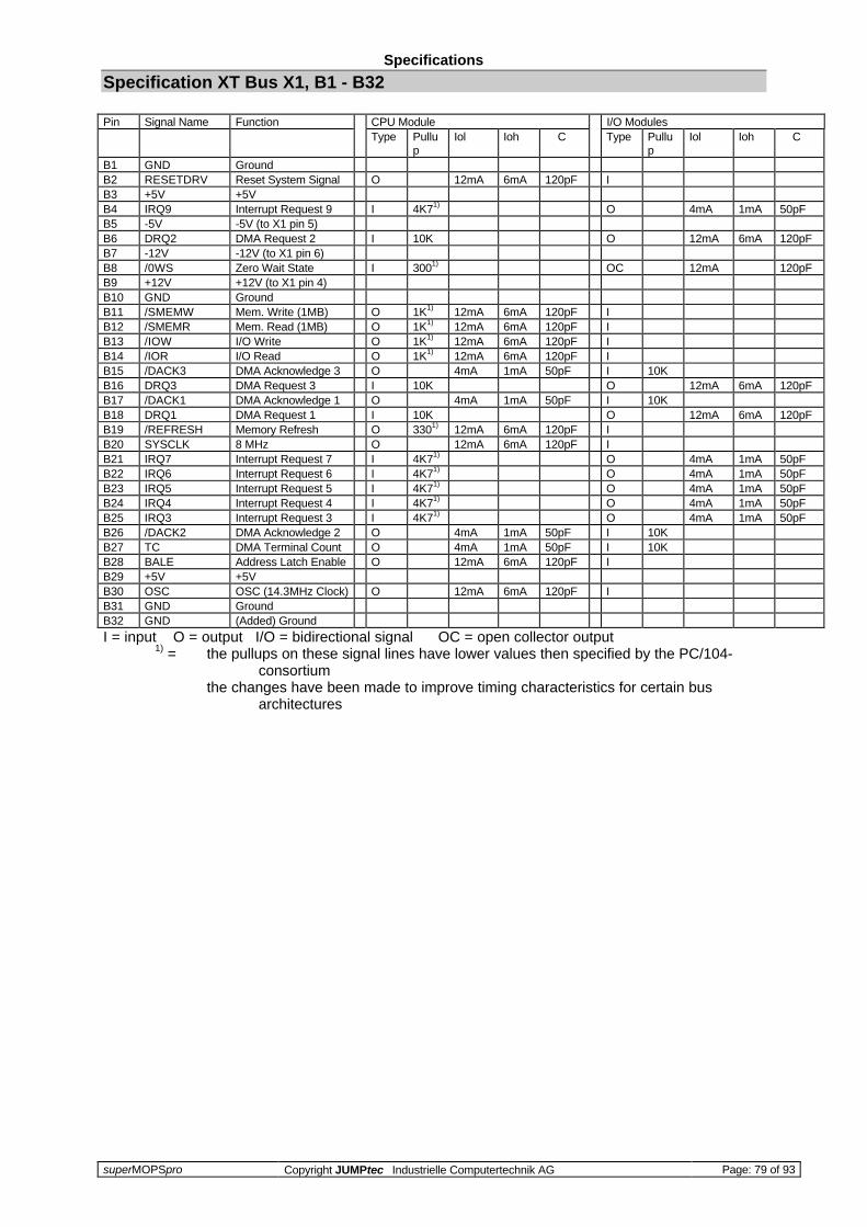
Specifications
superMOPSpro Copyright JUMPtec Industrielle Computertechnik AG Page: 79 of 93
Specification XT Bus X1, B1 - B32
Pin Signal Name Function CPU Module I/O ModulesType Pullu
pIol Ioh C Type Pullu
pIol Ioh C
B1 GND GroundB2 RESETDRV Reset System Signal O 12mA 6mA 120pF IB3 +5V +5VB4 IRQ9 Interrupt Request 9 I 4K71) O 4mA 1mA 50pFB5 -5V -5V (to X1 pin 5)B6 DRQ2 DMA Request 2 I 10K O 12mA 6mA 120pFB7 -12V -12V (to X1 pin 6)B8 /0WS Zero Wait State I 3001) OC 12mA 120pFB9 +12V +12V (to X1 pin 4)B10 GND GroundB11 /SMEMW Mem. Write (1MB) O 1K1) 12mA 6mA 120pF IB12 /SMEMR Mem. Read (1MB) O 1K1) 12mA 6mA 120pF IB13 /IOW I/O Write O 1K1) 12mA 6mA 120pF IB14 /IOR I/O Read O 1K1) 12mA 6mA 120pF IB15 /DACK3 DMA Acknowledge 3 O 4mA 1mA 50pF I 10KB16 DRQ3 DMA Request 3 I 10K O 12mA 6mA 120pFB17 /DACK1 DMA Acknowledge 1 O 4mA 1mA 50pF I 10KB18 DRQ1 DMA Request 1 I 10K O 12mA 6mA 120pFB19 /REFRESH Memory Refresh O 3301) 12mA 6mA 120pF IB20 SYSCLK 8 MHz O 12mA 6mA 120pF IB21 IRQ7 Interrupt Request 7 I 4K71) O 4mA 1mA 50pFB22 IRQ6 Interrupt Request 6 I 4K71) O 4mA 1mA 50pFB23 IRQ5 Interrupt Request 5 I 4K71) O 4mA 1mA 50pFB24 IRQ4 Interrupt Request 4 I 4K71) O 4mA 1mA 50pFB25 IRQ3 Interrupt Request 3 I 4K71) O 4mA 1mA 50pFB26 /DACK2 DMA Acknowledge 2 O 4mA 1mA 50pF I 10KB27 TC DMA Terminal Count O 4mA 1mA 50pF I 10KB28 BALE Address Latch Enable O 12mA 6mA 120pF IB29 +5V +5VB30 OSC OSC (14.3MHz Clock) O 12mA 6mA 120pF IB31 GND GroundB32 GND (Added) Ground
I = input O = output I/O = bidirectional signal OC = open collector output1) = the pullups on these signal lines have lower values then specified by the PC/104-
consortiumthe changes have been made to improve timing characteristics for certain bus
architectures

Specifications
superMOPSpro Copyright JUMPtec Industrielle Computertechnik AG Page: 80 of 93
Specification AT Bus X2, C0 - C19
Pin Signal Name Function CPU Module I/O ModulesType Pullu
pIol Ioh C Type Pullu
pIol Ioh C
C0 GND (Added) GroundC1 /SBHE Bus High Enable O 12mA 6mA 120pF IC2 LA23 Latch Address 23 O 12mA 6mA 120pF IC3 LA22 Latch Address 22 O 12mA 6mA 120pF IC4 LA21 Latch Address 21 O 12mA 6mA 120pF IC5 LA20 Latch Address 20 O 12mA 6mA 120pF IC6 LA19 Latch Address 19 O 12mA 6mA 120pF IC7 LA18 Latch Address 18 O 12mA 6mA 120pF IC8 LA17 Latch Address 17 O 12mA 6mA 120pF IC9 /MEMR Mem.Read High 1M O 1K1) 12mA 6mA 120pF IC10 /MEMW Mem.Write High 1M O 1K1) 12mA 6mA 120pF IC11 SD8 Data Bit 8 I/O 4K71) 12mA 6mA 120pF I/O 12mA 6mA 120pFC12 SD9 Data Bit 9 I/O 4K71) 12mA 6mA 120pF I/O 12mA 6mA 120pFC13 SD10 Data Bit 10 I/O 4K71) 12mA 6mA 120pF I/O 12mA 6mA 120pFC14 SD11 Data Bit 11 I/O 4K71) 12mA 6mA 120pF I/O 12mA 6mA 120pFC15 SD12 Data Bit 12 I/O 4K71) 12mA 6mA 120pF I/O 12mA 6mA 120pFC16 SD13 Data Bit 13 I/O 4K71) 12mA 6mA 120pF I/O 12mA 6mA 120pFC17 SD14 Data Bit 14 I/O 4K71) 12mA 6mA 120pF I/O 12mA 6mA 120pFC18 SD15 Data Bit 15 I/O 4K71) 12mA 6mA 120pF I/O 12mA 6mA 120pFC19 GND (Added) Ground
I = input O = output I/O = bidirectional signal OC = open collector output1) = the pullups on these signal lines have lower values then specified by the PC/104-
consortiumthe changes have been made to improve timing characteristics for certain bus
architectures
Specification AT Bus X2, D0 - D19
Pin Signal Name Function CPU Module I/O ModulesType Pullu
pIol Ioh C Type Pullu
pIol Ioh C
D0 GND (Added) GroundD1 /MEMCS16 16 Bit Mem.access I 3001) OC 12mA 120pFD2 /IOCS16 16 Bit I/O access I 3001) OC 12mA 120pFD3 IRQ10 Interrupt Request 10 I 4K71) O 4mA 1mA 50pFD4 IRQ11 Interrupt Request 11 I 4K71) O 4mA 1mA 50pFD5 IRQ12 Interrupt Request 12 I 4K71) O 4mA 1mA 50pFD6 IRQ15 Interrupt Request 13 I 4K71) O 4mA 1mA 50pFD7 IRQ14 Interrupt Request 14 I 4K71) O 4mA 1mA 50pFD8 /DACK0 DMA Acknowledge 0 O 4mA 1mA 50pF I 10KD9 DRQ0 DMA Request 0 I 10K O 12mA 6mA 120pFD10 /DACK5 DMA Acknowledge 5 O 4mA 1mA 50pF I 10KD11 DRQ5 DMA Request 5 I 10K O 12mA 6mA 120pFD12 /DACK6 DMA Acknowledge 6 O 4mA 1mA 50pF I 10KD13 DRQ6 DMA Request 6 I 10K O 12mA 6mA 120pFD14 /DACK7 DMA Acknowledge 7 O 4mA 1mA 50pF I 10KD15 DRQ7 DMA Request 6 I 10K O 12mA 6mA 120pFD16 +5V +5VD17 /MASTER Bus Master Assert I 3001) OC 12mA 120pFD18 GND GroundD19 GND (Added) Ground
I = input O = output I/O = bidirectional signal OC = open Collector output1) = the pullups on these signal lines have lower values then specified by the PC/104-
consortiumthe changes have been made to improve timing characteristics for certain bus
architectures

Signal Description
superMOPSpro Copyright JUMPtec Industrielle Computertechnik AG Page: 81 of 93
Signal Description
PC/104 Overview
Notation
Throughout the specification of the PC/104 interface the following convention is used for signalnotation. An "/" in front of a signal name indicates that the signal is active when it is at a low voltagelevel. A signal name without the beginning of a "/ " indicates that the signal is active when it is at ahigh voltage level.
General
The PC/104- bus is a stackable implementation of the industry standard (ISA) PC bus according toIEEE P996 specification. The PC/104 bus has additional signals and different mechanics than P996.The driver capability of the PC/104- Bus (6mA) is a quarter of a standard (ISA) PC bus (24mA). ThesuperMOPS/486DX-1 is developed with 12mA driver so it is the double of the PC/104 spec. FourPC/104 modules are useful to stack.
The included Features:
- full implementation of the industry standard (ISA) bus on signal level.- stackable bus for low cost and high reliable piggy back connections without backplane.- additional signals for improved control include:
battery connection, Reset input, XT/AT sense signal, and general purpose I/O pins.- keyboard and Mouse interface.- speed and sleep control signals.- serial control interface.- small footprint for embedded control applications.
Address / Data Signal Group
SD<0..15> (System Data Bus)bidirectional I/O pinsThese signals provide data bus bits 0 to 15 for the peripheral devices. All 8-bit devices useSD0 <0..7> for data transfers. The 16-bit devices will use SD<0..15>. To support 8-bitdevices, the data on SD<8..15> will be gated to SD<0..7> during 8-bit transfers to thesedevices. 16-bit CPU cycles will be converted to two 8-bit cycles for 8-bit peripheralautomatically.
SA<19..0> (System Address)output on CPU modulesinput on all other modulesAddress bits 0 through 15 are used to address I/O devices and address bits 0 through 19 areused to address memory within the system. These 20 address lines, in addition to LA<17..23>allow access of up to 16MB of memory. SA<0..19> are gated on the PC/104-bus when BALEis high and latched on falling edge of BALE.

Signal Description
superMOPSpro Copyright JUMPtec Industrielle Computertechnik AG Page: 82 of 93
LA<17..23> (Latchable Address Bus)output on CPU modulesinput on any other moduleThese signals (unlatched) are used to address memory up to 16 MB.
/SBHE (System Bus High Enable)output on CPU modulesinput on all other moduleBus High Enable indicates a transfer of data on the upper byte of the data bus (SD<8..15>).16 bit I/O devices use SBHE to condition data bus buffers tied to SD<8..15>.
BALE (Bus Address Latch Enable)output from CPU modulesinput on any other moduleBale is an active high pulse which is generated at the beginning of any bus cycle initiated by aCPU module. It indicates when the SA<0..19>, LA<17..23>, AEN, and /SBHE signals arevalid.
AEN (Address Enable)output from CPU modulesinput on any other moduleAEN is an active high output that indicates a DMA transfer cycle, only resources with a active/DACK signal should respond to the command lines when AEN is high.
Control Signal Group
/MEMR (Memory Read)output from CPU modulesinput on any other module/MEMR instructs memory devices to drive data onto the data bus. /MEMR is active on allmemory read cycles.
/SMEMR (System Memory Read)output from CPU modulesinput on any other module/SMEMR instructs memory devices to drive data onto the data bus. /SMEMR is active onmemory read cycles to addresses below 1MB.
/MEMW (Memory Write)output from CPU modulesinput on any other module/MEMW instructs memory devices to store the data present on the data bus. /MEMW isactive on all memory write cycles.
/SMEMW (System Memory Write)output from CPU modulesinput on any other module/SMEMW instructs memory devices to store the data present on the data bus. /SMEMW isactive on all memory write cycles to address below 1MB.

Signal Description
superMOPSpro Copyright JUMPtec Industrielle Computertechnik AG Page: 83 of 93
/IOR (I/O Read)output from CPU modulesinput on any other moduleI/O read instructs an I/O device to drive its data onto the data bus. It may be driven by theCPU or DMA controller. /IOR is inactive (high) during refresh cycles.
/IOW (I/O Write)output from CPU modulesinput on any other moduleI/O write instructs an I/O device to store the data present on the data bus. It may be driven bythe CPU or DMA controller. /IOW is inactive (high) during refresh cycles.
/IOCHCK (I/O Channel Check)input to CPU modulesopen collector output on any other module/IOCHCK is an active low input signal which indicates that an error has taken place on themodule bus. If I/O checking is enabled on the CPU module, an /IOCHCK assertion by aperipheral device generates an NMI to the processor.
IOCHRDY (I/O Channel Ready)input to CPU modulesopen collector output on any other moduleThe I/O channel ready is pulled low in order to extend the read or write cycles of any busaccess when required. The cycle can be initiated by the CPU, DMA controllers or refreshcontroller. The default number of wait states for cycles initiated by the CPU are 4 wait statesfor 8 bit peripherals and 1 wait state for 16 bit peripherals. One wait state is inserted as adefault for all DMA cycles. Any peripheral that cannot present read data or strobe in write datain this amount of time use IOCHRDY to extend these cycles.This signal should not be held low for more than 2,5 us for normal operation. Any extension tomore than 2,5 us does not guarantee proper DRAM memory contents because memoryrefresh is stopped while IOCHRDY is low.The IOCRDY signal is monitored on CPU modules, and if low (invalid) for more than 1,5seconds, the CPU module is resetted and booted like in a power up situation. This gives theuser the possibility to use this signal also as an external reset pin.
/MEMCS16 (16 Bit Memory Chip Select)input to CPU modulesopen collector output on any other moduleThe /MEMCS16 signal determines when a 16 bit to 8 bit conversion is needed for memorybus cycles. A conversion is done any time the CPU module is requesting a 16 bit memorycycle and the /MEMCS16 line is high. If /MEMCS16 is high, 16 bit CPU cycles are convertedinto two 8 bit cycles on the bus automatically. If /MEMCS16 is low, an access to peripherals isdone 16 bit wide.
/IOCS16 (16 Bit I/O Chip Select)input to CPU modulesopen collector output on any other moduleThe /IOCS16 signal determines when a 16 bit to 8 bit conversion is needed for I/O bus cycles.A conversion is done any time the CPU module is requesting a 16 bit I/O cycle and the/IOCS16 line is high. If /IOCS16 is high, 16 bit CPU cycles are converted into two 8 bit cycleson the bus automatically. If /IOCS16 is low, an access to peripherals is done 16 bit wide.

Signal Description
superMOPSpro Copyright JUMPtec Industrielle Computertechnik AG Page: 84 of 93
/REFRESH (Memory Refresh)output to CPU modulesinput on any other module/REFRESH is pulled low whenever a refresh cycle is initiated. A refresh cycle is activatedevery 15,6 us to prevent loss of DRAM data.
/OWS (0 Wait States)input to CPU modulesoutput on any other moduleThe Zero wait state signal tells the CPU to complete the current bus cycle without insertingthe default wait states. By default the CPU inserts 4 wait states for 8 bit transfers and 1 waitstate for 16 bit transfers.
Special Function Signal Group
/MASTER (MASTER bus request)input to CPU modulesopen collector output on any other moduleThis signal is used with a DRQ line to gain control of the system bus. A processor or DMAcontroller on the I/O channel may issue a DRQ to a DMA channel in cascade mode andreceive a /DACK. Upon receiving the /DACK, a bus master may pull /MASTER low, which willallow it to control the system address, data and control lines. After /MASTER is low, the busmaster must wait one system clock period before driving the address and data lines, and twoclock periods before issuing a read or write command. If this signal is held low for more than15 us, system memory may be lost because of lack of refresh.
SYSCLK (SYStem CLocK)output from a CPU moduleinput on any other moduleSYSCLK is supplied by the CPU module and has a nominal frequency of about 8 MHz with40-60 % duty cycle. Slower and higher frequencies may be supplied by different CPUmodules. This signal is supplied at all times, except when the CPU module is in sleep mode.
OSC (Oscillator frequency)output on CPU modulesinput on any other moduleOSC is supplied by CPU modules. It has a nominal frequency of 14,31818 MHz and a dutycycle of 40-60 %. This signal is supplied at all times, except when the CPU module is in sleepmode.
RESETDRV (Bus RESET)output on CPU modulesinput on any other moduleThis active high output is system reset generated from CPU modules to reset externaldevices.
DRQ<0..3, 5..7> (DMA Request)input to CPU modulesoutput on any other moduleThe asynchronous DMA request inputs are used by external devices to indicate when theyneed service from the CPU modules DAM controllers. DRQ<0..3> are used for transfersbetween 8 bit I/O adapters and system memory. DRQ<5..7> are used for transfers between16 bit I/O adapters and system memory. DRQ4 is not available externally. All DRQ pins havepullups on CPU modules.

Signal Description
superMOPSpro Copyright JUMPtec Industrielle Computertechnik AG Page: 85 of 93
/DACK<0..3, 5..7> (DMA Acknowledge)output on CPU modulesinput on any other moduleDMA acknowledge 0..5 and 5..7 are used to acknowledge DMA requests. They are low active.
T/C (Terminal Count))output on CPU modulesinput to all other moduleThe active high output TC indicates that one of the DMA channels has transferred al data.
IRQ<3..7, 9..12, 14,15> (Interrupt Requests)input to CPU modulesoutput on any other moduleThese are the asynchronous interrupt request lines. IRQ0, 1, 2, 8 and 13 are not available asexternal interrupts because they are used internally to CPU modules. All IRQ signals areactive high. The interrupt requests are prioritized, with IRQ9 through IRQ12 and IRQ14through IRQ15 having the highest priority (IRQ9 is the highest) and IRQ3 through IRQ7having the lowest priority (IRQ7 is the lowest). An interrupt request is generated when an IRQline is raised from low to high. The line must be held high until the CPU acknowledges theinterrupt request (interrupt service routine).

Signal Description
superMOPSpro Copyright JUMPtec Industrielle Computertechnik AG Page: 86 of 93
Data Conversion and Swapping
Data Conversion16 - bit transfers by the main CPU via the PC/104 - bus are converted into two 8 - bittransfers (low and high Byte ) if the control signals MEMCS16* or IOCS16* are not asserted.The higher Byte - Data (SD<15..8> ) is directed to SD <7..0> with SA0 =H during writecycles and from SD <7..0> to SD <15..0 > with SA0 =H during read cycles. This operation istransparent to the software .
Data SwappingData are swapped between SD <15..8 > and SD <7..0 > on the main CPU for odd Bytetransfers (SA0 =H) with 8 - bit devices on the PC/104 - bus. Swapping occurs also duringDMA cycles (SA0 =H) if the devices on the PC/104 - bus is a 16 - bit memory device and an8 - bit DMA channel is used for the transfer.
No. Description Min Typ Max Note1 Clock period (Tclk) 1252 BALE high width 543 SA<1..0> setup to BALE low 84 SBHE* setup to BALE low 205 SA<23..2> setup to BALE low 1306a Command width 16 bit cycles (zero wait states) 125 2)6b Command with 8 bit cycles (with 2 wait states) 325 3)7 SA<1..0> setup to command zero cmd delay 8 1)8 SBHE* setup to command zero cmd delay 20 1)9 SA<23..2> setup to command zero cmd delay 130 1)10 MEMCS16* , IOCS16* delay from SA<23..2> 8011 MEMCS16* , IOCS16* hold after SA<23..2 012a SA<1..0> hold after command 2312b SA<1..0> hold after SMEMR* or SMEMW* 1813a SBHE* hold after command 2313b SBHE* hold after SMEMR* or SMEMW* 1814a SA<23..2> hold after command 3014b SA<23..2> hold after SMEMR* or SMEMW* 2515 Write Data setup to command active 616 Read Data setup to command inactive 65 1)17a Write Data hold after command 4517b Read Data hold after command 018 IOCHRDY setup to CLK 3419 IOCHRDY hold after CLK 220 0WS* setup to CLK 2021 0WS* hold after CLK 0
Notes:1) Command delay programmable between 0 and 3 CLK/2 cycles seperately for 16
bit memory , 8 - bit memory and I/O cycles2) Command width depends on the number of wait states (programmable from 0 to 3 CLK
cycles) and command delay (note 1)3) Command width depends on the number of wait states (programmable from 2 to 5 CLK
cycles) and command delay (note 1)
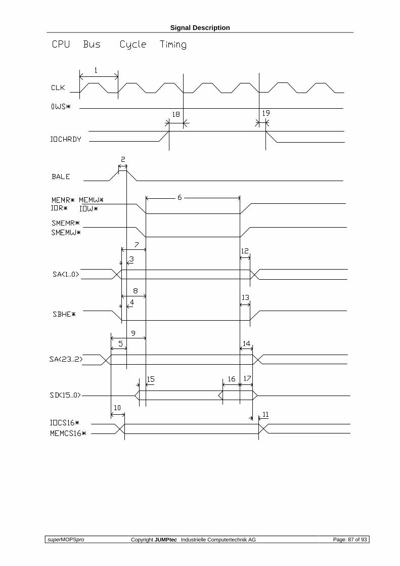
Signal Description
superMOPSpro Copyright JUMPtec Industrielle Computertechnik AG Page: 87 of 93
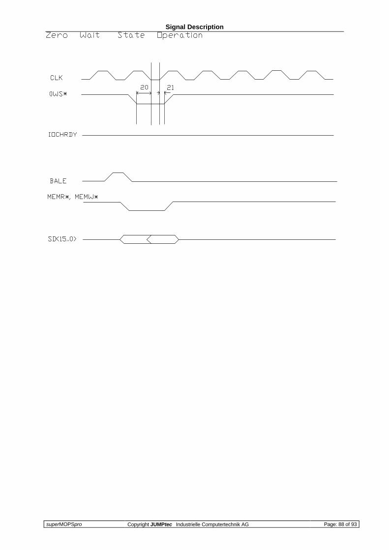
Signal Description
superMOPSpro Copyright JUMPtec Industrielle Computertechnik AG Page: 88 of 93

Signal Description
superMOPSpro Copyright JUMPtec Industrielle Computertechnik AG Page: 89 of 93
DMA Timing Specification
This section specifies the timing for Direct Memory Access cycles (all time in ns):No. Description MIN. TYP. MAX. Note1 Clock period (Tclk ) 1252 IOCHRDY setup to CLK 353 IOCHRDY hold from CLK 204 DRQ inactive delay from command 555 AEN setup to command 806 AEN hold from command 107 SA<23..0> setup to command 508 SA<23..0> hold from command 509 DACK setup to command 010 DACK hold from command 011 Extended Write delay 122 12812 Write command width 80 1)
(Extended Write , 0 Waitstates)13 Read inactive delay from Write 2014 T/C delay from command 16515 T/C hold from command 016 Read data setup 11017 Read data hold 018 Write data delay after command 80 2)19 Write data hold 15
Notes:1) with programmable wait states from 1 to 4 CLK cycles2) Note that this time cannot be extended by insertion of wait states
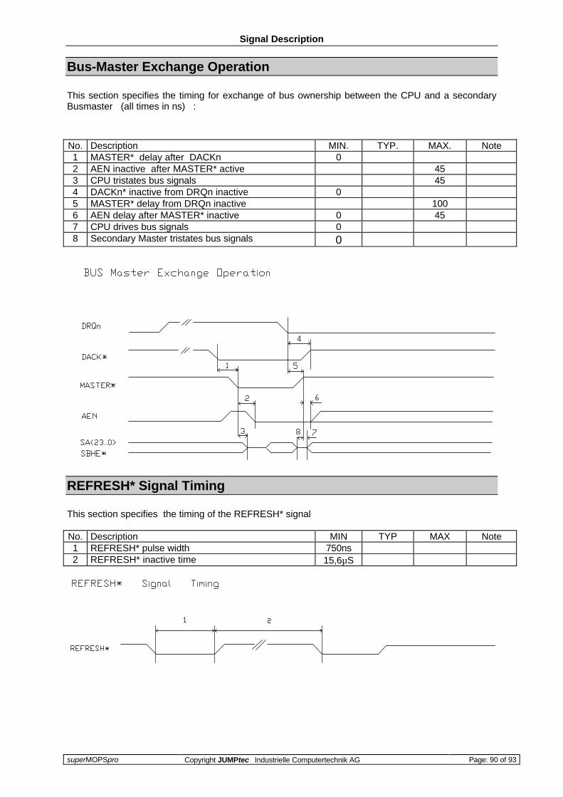
Signal Description
superMOPSpro Copyright JUMPtec Industrielle Computertechnik AG Page: 90 of 93
Bus-Master Exchange Operation
This section specifies the timing for exchange of bus ownership between the CPU and a secondaryBusmaster (all times in ns) :
No. Description MIN. TYP. MAX. Note1 MASTER* delay after DACKn 02 AEN inactive after MASTER* active 453 CPU tristates bus signals 454 DACKn* inactive from DRQn inactive 05 MASTER* delay from DRQn inactive 1006 AEN delay after MASTER* inactive 0 457 CPU drives bus signals 08 Secondary Master tristates bus signals 0
REFRESH* Signal Timing
This section specifies the timing of the REFRESH* signal
No. Description MIN TYP MAX Note1 REFRESH* pulse width 750ns2 REFRESH* inactive time 15,6µS
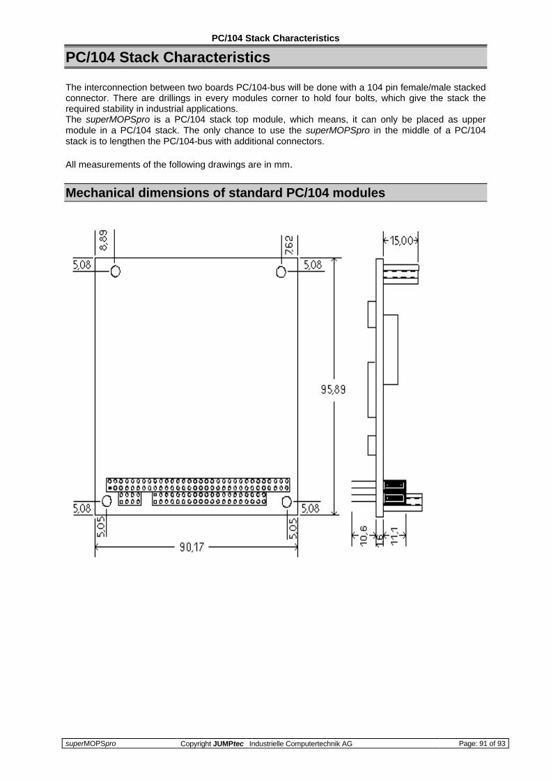
PC/104 Stack Characteristics
superMOPSpro Copyright JUMPtec Industrielle Computertechnik AG Page: 91 of 93
PC/104 Stack Characteristics
The interconnection between two boards PC/104-bus will be done with a 104 pin female/male stackedconnector. There are drillings in every modules corner to hold four bolts, which give the stack therequired stability in industrial applications.The superMOPSpro is a PC/104 stack top module, which means, it can only be placed as uppermodule in a PC/104 stack. The only chance to use the superMOPSpro in the middle of a PC/104stack is to lengthen the PC/104-bus with additional connectors.
All measurements of the following drawings are in mm.
Mechanical dimensions of standard PC/104 modules

PC/104 Stack Characteristics
superMOPSpro Copyright JUMPtec Industrielle Computertechnik AG Page: 92 of 93
Self stacking system (Standard) with superMOPSpro
Customized System with superMOPSpro

History
superMOPSpro Copyright JUMPtec Industrielle Computertechnik AG Page: 93 of 93
History
Filename Date Edited by Alteration to preceding revisionP487D112.DOC M. Schanz CreatedP487D212.DOC 6.2.96 H. Iglhaut FormattedP487_neu.DOC 22.11.96 M. Huber Ethernet added, graphics changedP487D312.DOC 2.2.97 E.Eras Text revised, IRDA addedP487D210.DOC 14.10.97 H.Bruhn Changed file name to regular JUMP standard, Manual
completely revisedP487D220.DOC 15.10.97 H.Bruhn Changed to JUMPtecP487D221.DOC 12.01.1998 SG Changed to Brunnwiesenstr.P487m222.DOC 09.02.98 J. Hagn Layout revised and filename corrected